EP2551185A1 - Underwater or marine vehicle and associated docking method - Google Patents
Underwater or marine vehicle and associated docking method Download PDFInfo
- Publication number
- EP2551185A1 EP2551185A1 EP12177504A EP12177504A EP2551185A1 EP 2551185 A1 EP2551185 A1 EP 2551185A1 EP 12177504 A EP12177504 A EP 12177504A EP 12177504 A EP12177504 A EP 12177504A EP 2551185 A1 EP2551185 A1 EP 2551185A1
- Authority
- EP
- European Patent Office
- Prior art keywords
- cable
- machine
- marine
- clamp
- detection means
- Prior art date
- Legal status (The legal status is an assumption and is not a legal conclusion. Google has not performed a legal analysis and makes no representation as to the accuracy of the status listed.)
- Granted
Links
- 238000000034 method Methods 0.000 title claims abstract description 8
- 238000003032 molecular docking Methods 0.000 title description 3
- 238000011084 recovery Methods 0.000 claims abstract description 26
- 238000001514 detection method Methods 0.000 claims description 25
- 230000008878 coupling Effects 0.000 abstract description 6
- 238000010168 coupling process Methods 0.000 abstract description 6
- 238000005859 coupling reaction Methods 0.000 abstract description 6
- XLYOFNOQVPJJNP-UHFFFAOYSA-N water Substances O XLYOFNOQVPJJNP-UHFFFAOYSA-N 0.000 description 2
- 230000000295 complement effect Effects 0.000 description 1
- 238000006073 displacement reaction Methods 0.000 description 1
- 238000007654 immersion Methods 0.000 description 1
- 238000007689 inspection Methods 0.000 description 1
- 238000012423 maintenance Methods 0.000 description 1
- 239000003381 stabilizer Substances 0.000 description 1
Images


Classifications
-
- B—PERFORMING OPERATIONS; TRANSPORTING
- B63—SHIPS OR OTHER WATERBORNE VESSELS; RELATED EQUIPMENT
- B63G—OFFENSIVE OR DEFENSIVE ARRANGEMENTS ON VESSELS; MINE-LAYING; MINE-SWEEPING; SUBMARINES; AIRCRAFT CARRIERS
- B63G8/00—Underwater vessels, e.g. submarines; Equipment specially adapted therefor
- B63G8/001—Underwater vessels adapted for special purposes, e.g. unmanned underwater vessels; Equipment specially adapted therefor, e.g. docking stations
-
- B—PERFORMING OPERATIONS; TRANSPORTING
- B63—SHIPS OR OTHER WATERBORNE VESSELS; RELATED EQUIPMENT
- B63B—SHIPS OR OTHER WATERBORNE VESSELS; EQUIPMENT FOR SHIPPING
- B63B21/00—Tying-up; Shifting, towing, or pushing equipment; Anchoring
- B63B21/56—Towing or pushing equipment
- B63B21/58—Adaptations of hooks for towing; Towing-hook mountings
-
- B—PERFORMING OPERATIONS; TRANSPORTING
- B63—SHIPS OR OTHER WATERBORNE VESSELS; RELATED EQUIPMENT
- B63B—SHIPS OR OTHER WATERBORNE VESSELS; EQUIPMENT FOR SHIPPING
- B63B21/00—Tying-up; Shifting, towing, or pushing equipment; Anchoring
- B63B21/56—Towing or pushing equipment
- B63B21/66—Equipment specially adapted for towing underwater objects or vessels, e.g. fairings for tow-cables
-
- B—PERFORMING OPERATIONS; TRANSPORTING
- B63—SHIPS OR OTHER WATERBORNE VESSELS; RELATED EQUIPMENT
- B63B—SHIPS OR OTHER WATERBORNE VESSELS; EQUIPMENT FOR SHIPPING
- B63B27/00—Arrangement of ship-based loading or unloading equipment for cargo or passengers
- B63B27/18—Arrangement of ship-based loading or unloading equipment for cargo or passengers of cableways, e.g. with breeches-buoys
-
- B—PERFORMING OPERATIONS; TRANSPORTING
- B63—SHIPS OR OTHER WATERBORNE VESSELS; RELATED EQUIPMENT
- B63C—LAUNCHING, HAULING-OUT, OR DRY-DOCKING OF VESSELS; LIFE-SAVING IN WATER; EQUIPMENT FOR DWELLING OR WORKING UNDER WATER; MEANS FOR SALVAGING OR SEARCHING FOR UNDERWATER OBJECTS
- B63C11/00—Equipment for dwelling or working underwater; Means for searching for underwater objects
- B63C11/34—Diving chambers with mechanical link, e.g. cable, to a base
- B63C11/36—Diving chambers with mechanical link, e.g. cable, to a base of closed type
- B63C11/42—Diving chambers with mechanical link, e.g. cable, to a base of closed type with independent propulsion or direction control
-
- B—PERFORMING OPERATIONS; TRANSPORTING
- B63—SHIPS OR OTHER WATERBORNE VESSELS; RELATED EQUIPMENT
- B63G—OFFENSIVE OR DEFENSIVE ARRANGEMENTS ON VESSELS; MINE-LAYING; MINE-SWEEPING; SUBMARINES; AIRCRAFT CARRIERS
- B63G8/00—Underwater vessels, e.g. submarines; Equipment specially adapted therefor
- B63G8/42—Towed underwater vessels
-
- B—PERFORMING OPERATIONS; TRANSPORTING
- B63—SHIPS OR OTHER WATERBORNE VESSELS; RELATED EQUIPMENT
- B63B—SHIPS OR OTHER WATERBORNE VESSELS; EQUIPMENT FOR SHIPPING
- B63B27/00—Arrangement of ship-based loading or unloading equipment for cargo or passengers
- B63B27/16—Arrangement of ship-based loading or unloading equipment for cargo or passengers of lifts or hoists
- B63B2027/165—Deployment or recovery of underwater vehicles using lifts or hoists
-
- B—PERFORMING OPERATIONS; TRANSPORTING
- B63—SHIPS OR OTHER WATERBORNE VESSELS; RELATED EQUIPMENT
- B63G—OFFENSIVE OR DEFENSIVE ARRANGEMENTS ON VESSELS; MINE-LAYING; MINE-SWEEPING; SUBMARINES; AIRCRAFT CARRIERS
- B63G8/00—Underwater vessels, e.g. submarines; Equipment specially adapted therefor
- B63G8/001—Underwater vessels adapted for special purposes, e.g. unmanned underwater vessels; Equipment specially adapted therefor, e.g. docking stations
- B63G2008/002—Underwater vessels adapted for special purposes, e.g. unmanned underwater vessels; Equipment specially adapted therefor, e.g. docking stations unmanned
- B63G2008/004—Underwater vessels adapted for special purposes, e.g. unmanned underwater vessels; Equipment specially adapted therefor, e.g. docking stations unmanned autonomously operating
Definitions
- the present invention relates to the field of submarine or marine gear, and in particular a device for securing such a machine.
- a particularly interesting application of the invention relates to the recovery of a submersible machine by a traction cable, in order to be brought back to the surface of the water, for example on the deck of a ship, either directly or by via a mobile receiving part.
- the invention also relates to the recovery of a submersible machine by a traction cable to be recovered for example by a submarine.
- An autonomous submersible vehicle called “AUV” (Autonomous Underwater Vehicle in Anglo-Saxon terms)
- AAV Autonomous Underwater Vehicle in Anglo-Saxon terms
- the mobile part generally called “cage” comprises a frame defining a housing inside which the machine can enter to be recovered.
- the document WO 01/21476 describes a submersible device for launching, maintenance and recovery of a submersible vehicle comprising in particular a recovery platform comprising a first connection to a surface vehicle and a second connection to a submersible vehicle.
- the submersible vehicle comprises for this purpose a connection means of complementary shape to the second connection of the recovery platform.
- Such a recovery device is complex and does not allow effective attachment of the marine machine to a traction cable.
- the object of the present invention is to overcome the disadvantages of the state of the art.
- the object of the invention is to propose a submersible machine comprising its own securing means in a marine environment so as to be autonomous while effectively clinging to a recovery cable which can be a traction cable and avoiding the influence of vertical movements due to the swell.
- the invention relates to a marine or submarine device intended to be secured to a recovery cable.
- the machine comprises non-contact detection means of the recovery cable capable of detecting the cable and guiding the machine towards the cable and cable hooking means located on the machine.
- the marine or submarine device finds the cable by detection and is then guided by its own detection means to a tow rope that can be ballasted, the cable is then locked effectively to the machine by means of 'hanging located at the front of the machine.
- the gear thus secured may, for example, be subsequently towed in a moving part such as a receiving cage or directly on a ramp in order to be reassembled, if it is immersed, on the surface of the water.
- the attachment means are located at one end of the machine, but may also be located on the outer surface of the body of the machine.
- the attachment means comprise at least one hook and at least one clamp movable in rotation between a closed position in contact with the outer surface of the machine, an open position deviating from the outer surface of the machine for provide a wide cable receiving opening and a hooking position in which the clamp cooperates with the hook to leave a space for the passage of the cable between the clamp and the outer surface of the marine gear.
- the clip includes a cable-contact sensing portion.
- the attachment means may comprise at least one locking valve located in the hook for the passage of the cable.
- the marine machine comprises an electronic control unit capable of directing the marine machine towards the traction cable as a function of the non-contact detection means, of controlling the position of the clamp according to the data provided by the detection portion. by contact, and lock the flapper after the cable passage.
- the machine may include one or more forceps judiciously located on the machine.
- the machine is, for example, autonomous and includes internal propulsion means.
- the contactless detection means comprise at least one sensor which can be acoustic (for example a sonar), laser or video.
- the invention relates to a method for attaching a marine gear to a recovery cable in which the cable is detected and the marine gear is guided towards the cable by non-contact detection means and hooks the cable by hooking means which can be located at one end or on the sides of the marine machine.
- a clip is actuated in an open position away from the outer surface of the machine.
- the clamp When the cable is detected by contact detection means located on the clamp, the clamp can be actuated in a hooking position in which the clamp cooperates with a hook to leave a space for the passage of the cable between the clamp and the outer surface of the marine gear.
- the cable when the cable is in the space between the clamp and the outer surface of the marine machine, the cable is slid to a lock valve in the hook and locked the cable by locking the valve.
- a marine or underwater vehicle As illustrated on the figures 1 and 2 , a marine or underwater vehicle, referenced 1 as a whole, is intended to be recovered by a recovery device (not shown) connected for example by hoisting ropes to a boat or a naval surface vehicle (not shown) .
- the recovery device comprises, for example, a moving part (not shown), such as a receiving cage and a traction cable 2, a first end 2a is connected to a front end of the receiving cage, for example to a pulling winch (not shown) and a second free end 2b intended to be hooked by the machine 1.
- the invention is not limited to the use of such a receiving cage to recover the marine gear. Any other means of recovering a marine gear by means of a traction cable may be used, in particular the recovery of the craft by a submersible.
- the vehicle 1 may, for example, be a submersible or floating underwater vehicle and designed, for example, to perform surveillance and / or underwater inspection.
- the underwater vehicle 1 extends along a longitudinal axis and comprises a main body 3 of generally cylindrical shape, or torpedo.
- the body 3 is provided with a stabilizer 4 fixed to a rear end 3a and provided to ensure the stability of the displacement of the vehicle 1, and longitudinal thrusters 5 fixed on one side and the other of the body 3 forward
- the vehicle 1 also comprises a front portion 3b which may, for example, comprise a camera (not shown) for observing the seabed.
- the vehicle 1 is thus autonomous and includes its own means of internal propulsion.
- the machine 1 illustrated at figure 1 is attached to one end 2b of the traction cable 2, the other end 2a is intended to be connected to a recovery device (not shown).
- the figure 2 illustrates the machine 1 ready to dock at the weighted end 2b of the traction cable 2.
- a float (not shown) could be hooked to the traction cable to ensure the verticality of the cable, in particular as part of the recovery of the craft by a submersible.
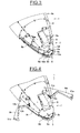
- the front part 3b of the machine 1, illustrated in detail on the Figures 3 to 5 comprises non-contact detection means 6 of the traction cable 2, such as a sonar, capable of guiding the machine 1 towards the traction cable 2 and the hooking means 7 of the cable 2 situated at a front end 3b 1.
- the non-contact detection means 6 is located on the upper part of the machine 1, in a housing 6a provided for this purpose.
- the non-contact detection means 6 may, for example, be controlled to exit this housing 6a in order to look for the traction cable 2. It will be noted that the non-contact detection means could also be directly attached to the outer surface of the housing. gear 1.
- the attachment means 7 comprise a set of hooks 8 located at the end of the front portion 3b of the machine 1, two clamps 9a, 9b and two locking valves 13a, 13b each located in a hook 8 for the passage cable 2.
- the set of hooks 8 for example of the double hook type, comprises a base 8a of substantially conical shape matching the end of the front portion 3a of the machine 1, a rigid rod 8b and two curved tips 8c, 8d around the base 8a.
- a single curved tip 8c forming a single hook.
- the clamps 9a, 9b are rotatable between a closed position, visible on the figure 3 , in contact with the outer surface 3c of the machine 1, an open position, visible on the figures 2 and 4 , deviating from the outer surface 3c of the machine 1 and a hooking position, visible on the figures 1 and 5 , in which each clamp 9a, 9b cooperates with a curved tip 8c, 8d so as to leave a space E for the passage of the cable 2 between each clamp 9a, 9b and the outer surface 3c of the machine 1.
- a single clamp 9a could be used.
- Each clamp 9a, 9b comprises a base 10a, 10b connected to a pivoting mechanism (not shown), comprising for example a set of cylinders, and a protruding portion 11a, 11b outwardly of generally parallelepipedal shape.
- the front part 3b of the machine 1 has grooves 9c in which the tongs 9a, 9b are housed in the closed position visible on the figure 3 .
- the closed position corresponds in particular to a transit position.
- the parts of the clamp 9a, 9b located in the housings 9c of the machine 1 are shown in dotted lines in the figures.
- a stud 9d can be placed inside the machine 1 in order to avoid the contact between the clamps 9a, 9b when they are in the closed position.
- the arrangement of the clamps 9a, 9b in the recesses provided for this purpose in the body 3 of the machine 1 makes it possible to prevent the clamps 9a, 9b from clinging to elements during the transit of the machine 1.
- Each base 10a, 10b comprises a detection portion 12a, 12b by contact of the cable 2.
- the machine 1 further comprises an electronic control unit (not shown) capable of directing the machine 1 towards the traction cable 2 as a function of the non-contact detection means 6, to control the position of the clamps 9a, 9b in function data provided by the contact detection portion 12a, 12b, and lock the corresponding valve 13a, 13b after the cable passage 2.
- an electronic control unit capable of directing the machine 1 towards the traction cable 2 as a function of the non-contact detection means 6, to control the position of the clamps 9a, 9b in function data provided by the contact detection portion 12a, 12b, and lock the corresponding valve 13a, 13b after the cable passage 2.
- the catching means 7 are located elsewhere than at the front end 3b of the machine 1, in fact, it could be provided a hooking of the traction cable 2 for example by the top of the machine 1.
- the grippers 9a, 9b are actuated simultaneously by the electronic control unit in an open position deviating from the outer surface 3c of the machine 1, as visible on the figures 2 and 4 .
- each clamp 9a, 9b When the traction cable 2 is detected by one of the contact detection means 12a, 12b respectively located on a clamp 9a, 9b, the clamps 9a, 9b are simultaneously actuated in a hooking position, visible on the figure 3 , in which each clamp 9a, 9b cooperates with a curved end 8c, 8d so as to leave a space E for the passage of the cable 2 between the clamp 9a, 9b and the outer surface 3c of the machine 1.
- the propulsion means (not shown) of the machine 1 are stopped so that the traction cable 2 slides towards the rigid rod 8b, and slides through one of the locking valves 13a, 13b located in the hook 8 to its weighted end serving as a stop.
- the electronic control unit actuates the locking valve 13a, 13b to prevent the cable 2 from going back and thus allows effective locking of the traction cable 2 by the machine 1.
- the machine 1 hooked to the traction cable 2 the machine 1 is towed, for example using a winch in a receiving cage to position the front, called "nose", of the gear 1 in a docking means, for example in a mobile receiving cone.
- the machine 1 and housed in the cage can then be raised to the surface.
- the invention is not limited to the use of such a receiving cage to recover the marine gear. Any other means of recovering a marine gear by means of a traction cable may be used.
- the marine or underwater vehicle is able to dock autonomously to a traction cable by effective hooking means providing multiple benefits, such as the possible recovery of the machine from n any structure, fixed or mobile, aerial or submerged, with a weighted cable.
- the possible recovery of the machine in immersion makes it possible to overcome the influence of the swell.
- such a coupling device can be easily adapted to existing systems, for example by using a cable equipped with an end ballast and also requires no human intervention at sea.
Landscapes
- Engineering & Computer Science (AREA)
- Mechanical Engineering (AREA)
- Ocean & Marine Engineering (AREA)
- Chemical & Material Sciences (AREA)
- Combustion & Propulsion (AREA)
- Aviation & Aerospace Engineering (AREA)
- Laying Of Electric Cables Or Lines Outside (AREA)
- Measurement Of Velocity Or Position Using Acoustic Or Ultrasonic Waves (AREA)
Abstract
Description
La présente invention concerne le domaine des engins sous-marins ou marins, et en particulier un dispositif d'arrimage d'un tel engin.The present invention relates to the field of submarine or marine gear, and in particular a device for securing such a machine.
Une application particulièrement intéressante de l'invention concerne la récupération d'un engin submersible par un câble de traction, afin d'être ramené à la surface de l'eau, par exemple sur le pont d'un navire, soit directement, soit par l'intermédiaire d'une partie mobile de réception. L'invention concerne aussi la récupération d'un engin submersible par un câble de traction afin d'être récupéré par exemple par un sous-marin.A particularly interesting application of the invention relates to the recovery of a submersible machine by a traction cable, in order to be brought back to the surface of the water, for example on the deck of a ship, either directly or by via a mobile receiving part. The invention also relates to the recovery of a submersible machine by a traction cable to be recovered for example by a submarine.
Un engin submersible autonome, dit « AUV » (Autonomous Underwater Vehicle en terme anglo-saxon), est, en général, récupéré par des moyens de treuillage fixés sur un véhicule naval de surface et une partie mobile de réception de l'engin. Plus particulièrement, la partie mobile, appelée généralement « cage » comprend un châssis définissant un logement à l'intérieur duquel l'engin peut pénétrer pour être récupéré.An autonomous submersible vehicle, called "AUV" (Autonomous Underwater Vehicle in Anglo-Saxon terms), is generally recovered by winching means fixed on a surface naval vehicle and a mobile receiving part of the craft. More particularly, the mobile part, generally called "cage" comprises a frame defining a housing inside which the machine can enter to be recovered.
Le document
En effet, lors de fortes houles, un tel système d'accrochage est difficile à mettre en oeuvre.Indeed, during heavy swells, such a fastening system is difficult to implement.
On peut également se référer au document
Toutefois, il est nécessaire d'aligner convenablement l'engin avec le cône de réception afin que celui-ci puisse être récupéré convenablement dans l'appareil de récupération.However, it is necessary to properly align the machine with the receiving cone so that it can be recovered properly in the recovery device.
De tels dispositifs ne sont pas adaptés en cas de mer agitée, en raison de mouvements des moyens de récupération générés par la houle et qui empêcheraient l'engin submersible d'être récupéré convenablement sans être endommagé.Such devices are not suitable in case of rough sea, due to movements of the recovery means generated by the swell and which would prevent the submersible machine to be recovered properly without being damaged.
De plus, aucun de ces documents ne propose un engin submersible capable de s'arrimer de façon autonome à un câble de traction.In addition, none of these documents offers a submersible device capable of docking autonomously to a traction cable.
Le but de la présente invention est de pallier les inconvénients de l'état de la technique.The object of the present invention is to overcome the disadvantages of the state of the art.
Le but de l'invention est de proposer un engin submersible comprenant ses propres moyens d'arrimage en milieu marin afin d'être autonome tout en s'accrochant de façon efficace à un câble de récupération qui peut être un câble de traction et en évitant l'influence des mouvements verticaux dus à la houle.The object of the invention is to propose a submersible machine comprising its own securing means in a marine environment so as to be autonomous while effectively clinging to a recovery cable which can be a traction cable and avoiding the influence of vertical movements due to the swell.
L'invention a pour objet un engin marin ou sous-marin destiné à être arrimé à un câble de récupération. L'engin comprend des moyens de détection sans contact du câble de récupération capables de détecter le câble et de guider l'engin vers le câble et des moyens d'accrochage du câble situés sur l'engin.The invention relates to a marine or submarine device intended to be secured to a recovery cable. The machine comprises non-contact detection means of the recovery cable capable of detecting the cable and guiding the machine towards the cable and cable hooking means located on the machine.
Ainsi, l'engin marin ou sous-marin retrouve le câble par détection et est ensuite guidé par ses propres moyens de détection vers un câble de traction qui peut être lesté, le câble est ensuite verrouillé efficacement à l'engin grâce à des moyens d'accrochage situés à l'avant de l'engin. L'engin ainsi arrimé peut, par exemple, être ensuite tracté dans une partie mobile telle qu'une cage de réception ou directement sur une rampe afin d'être remonté, s'il est immergé, à la surface de l'eau.Thus, the marine or submarine device finds the cable by detection and is then guided by its own detection means to a tow rope that can be ballasted, the cable is then locked effectively to the machine by means of 'hanging located at the front of the machine. The gear thus secured may, for example, be subsequently towed in a moving part such as a receiving cage or directly on a ramp in order to be reassembled, if it is immersed, on the surface of the water.
Avantageusement, les moyens d'accrochage sont situés à une extrémité de l'engin, mais peuvent également être situés sur la surface extérieure du corps de l'engin.Advantageously, the attachment means are located at one end of the machine, but may also be located on the outer surface of the body of the machine.
Avantageusement, les moyens d'accrochage comprennent au moins un crochet et au moins une pince mobile en rotation entre une position fermée en contact avec la surface extérieure de l'engin, une position ouverte s'écartant de la surface extérieure de l'engin pour offrir une large ouverture de réception du câble et une position d'accrochage dans laquelle la pince coopère avec le crochet afin de laisser subsister un espace pour le passage du câble entre la pince et la surface extérieure de l'engin marin.Advantageously, the attachment means comprise at least one hook and at least one clamp movable in rotation between a closed position in contact with the outer surface of the machine, an open position deviating from the outer surface of the machine for provide a wide cable receiving opening and a hooking position in which the clamp cooperates with the hook to leave a space for the passage of the cable between the clamp and the outer surface of the marine gear.
Par exemple, la pince comprend une portion de détection par contact du câble.For example, the clip includes a cable-contact sensing portion.
Les moyens d'accrochage peuvent comprendre au moins un clapet de verrouillage situé dans le crochet pour le passage du câble.The attachment means may comprise at least one locking valve located in the hook for the passage of the cable.
Avantageusement, l'engin marin comprend une unité de commande électronique capable de diriger l'engin marin vers le câble de traction en fonction des moyens de détection sans contact, de commander la position de la pince en fonction des données fournies par la portion de détection par contact, et de verrouiller le clapet après le passage câble.Advantageously, the marine machine comprises an electronic control unit capable of directing the marine machine towards the traction cable as a function of the non-contact detection means, of controlling the position of the clamp according to the data provided by the detection portion. by contact, and lock the flapper after the cable passage.
L'engin peut comprendre une ou plusieurs pinces judicieusement situées sur l'engin.The machine may include one or more forceps judiciously located on the machine.
L'engin est, par exemple, autonome et comprend des moyens de propulsion interne.The machine is, for example, autonomous and includes internal propulsion means.
Avantageusement, les moyens de détection sans contact comprennent au moins un capteur qui peut être acoustique (par exemple un sonar), laser ou vidéo.Advantageously, the contactless detection means comprise at least one sensor which can be acoustic (for example a sonar), laser or video.
Selon un autre aspect, l'invention concerne un procédé d'accrochage d'un engin marin à un câble de récupération dans lequel on détecte le câble et on guide l'engin marin vers le câble par des moyens de détection sans contact et on accroche le câble par des moyens d'accrochage qui peuvent être situés à une extrémité ou sur les côtés de l'engin marin.According to another aspect, the invention relates to a method for attaching a marine gear to a recovery cable in which the cable is detected and the marine gear is guided towards the cable by non-contact detection means and hooks the cable by hooking means which can be located at one end or on the sides of the marine machine.
Avantageusement, lorsque le câble est détecté par les moyens de détection sans contact, on actionne une pince dans une position ouverte s'écartant de la surface extérieure de l'engin.Advantageously, when the cable is detected by the non-contact detection means, a clip is actuated in an open position away from the outer surface of the machine.
Lorsque le câble est détecté par des moyens de détection par contact situés sur la pince, on peut actionner la pince dans une position d'accrochage dans laquelle la pince coopère avec un crochet afin de laisser subsister un espace pour le passage du câble entre la pince et la surface extérieure de l'engin marin.When the cable is detected by contact detection means located on the clamp, the clamp can be actuated in a hooking position in which the clamp cooperates with a hook to leave a space for the passage of the cable between the clamp and the outer surface of the marine gear.
En outre, lorsque le câble se trouve dans l'espace entre la pince et la surface extérieure de l'engin marin, on laisse coulisser le câble vers un clapet de verrouillage situé dans le crochet et on verrouille le câble par verrouillage du clapet.In addition, when the cable is in the space between the clamp and the outer surface of the marine machine, the cable is slid to a lock valve in the hook and locked the cable by locking the valve.
D'autres buts, caractéristiques et avantages de l'invention apparaîtront à la lecture de la description suivante, donnée uniquement à titre d'exemple non limitatif, et faite en référence aux dessins annexés sur lesquels :
- la
figure 1 est une vue générale d'un engin marin récupéré par un câble de traction ; - la
figure 2 est une vue générale de l'engin marin en vue d'être récupéré par le câble de traction ; et - les
figures 3, 4 ,5 représentent la partie avant de l'engin marin selon lafigure 1 illustrant différentes positions des moyens d'accrochage.
- the
figure 1 is a general view of a marine craft recovered by a traction cable; - the
figure 2 is a general view of the marine gear for recovery by the towing cable; and - the
Figures 3, 4 ,5 represent the front part of the marine gear according to thefigure 1 illustrating different positions of the attachment means.
Tel qu'il est illustré sur les
La cage de réception, décrite dans la demande de brevet français N°
On notera que l'invention ne se limite par à l'utilisation d'une telle cage de réception afin de récupérer l'engin marin. Tout autre moyen de récupération d'un engin marin par le biais d'un câble de traction peut être utilisé, notamment la récupération de l'engin par un submersible.Note that the invention is not limited to the use of such a receiving cage to recover the marine gear. Any other means of recovering a marine gear by means of a traction cable may be used, in particular the recovery of the craft by a submersible.
L'engin 1 peut, par exemple, être un véhicule sous-marin submersible ou flottant et conçu, par exemple, pour réaliser une surveillance et/ou une inspection sous-marine. L'engin sous marin 1 s'étend selon un axe longitudinal et comprend un corps principal 3 de forme générale cylindrique, ou torpille. Le corps 3 est pourvu d'un empennage 4 fixé à une extrémité arrière 3a et prévu pour assurer la stabilité du déplacement de l'engin 1, et de propulseurs longitudinaux 5 fixés d'un côté et de l'autre du corps 3 en avant de l'empennage 4. L'engin 1 comprend également une partie avant 3b pouvant, par exemple, comprendre une caméra (non représentée) pour l'observation des fonds sous-marins. L'engin 1 est ainsi autonome et comprend ses propres moyens de propulsion interne.The
L'engin 1 illustré à la
La partie avant 3b de l'engin 1, illustrée en détails sur les
Les moyens d'accrochage 7 comprennent un ensemble de crochets 8 situés à l'extrémité de la partie avant 3b de l'engin 1, deux pinces 9a, 9b et deux clapets de verrouillage 13a, 13b situés chacun dans un crochet 8 pour le passage du câble 2.The attachment means 7 comprise a set of
L'ensemble de crochets 8, par exemple de type hameçon double, comprend une embase 8a de forme substantiellement conique épousant l'extrémité de la partie avant 3a de l'engin 1, une tige rigide 8b et deux pointes recourbées 8c, 8d autour de l'embase 8a. On pourrait prévoir, à titre de variante, l'utilisation d'une seule pointe recourbée 8c, formant un hameçon simple.The set of
Les pinces 9a, 9b sont mobiles en rotation entre une position fermée, visible sur la
Chaque pince 9a, 9b comprend une embase 10a, 10b reliée à un mécanisme de pivotement (non représenté), comportant par exemple un ensemble de vérins, et une partie en saillie 11a, 11b vers l'extérieur, de forme générale parallélépipédique. La partie avant 3b de l'engin 1 comporte des rainures 9c dans lesquelles viennent se loger les pinces 9a, 9b en position fermée visible sur la
Chaque embase 10a, 10b comporte une portion de détection 12a, 12b par contact du câble 2.Each
L'engin 1 comprend en outre une unité de commande électronique (non représentée) capable de diriger l'engin 1 vers le câble de traction 2 en fonction des moyens de détection sans contact 6, de commander la position des pinces 9a, 9b en fonction des données fournies par la portion de détection par contact 12a, 12b, et de verrouiller le clapet 13a, 13b correspondant après le passage câble 2.The
On ne sort pas du cadre de l'invention lorsque les moyens d'accrochages 7 sont situés ailleurs qu'à l'extrémité avant 3b de l'engin 1, en effet, on pourrait prévoir un accrochage du câble de traction 2 par exemple par le dessus de l'engin 1.It is not beyond the scope of the invention when the catching means 7 are located elsewhere than at the
Le procédé d'accrochage de l'engin 1 à un câble de traction 2 est le suivant :
- Dans une première étape,
l'engin 1 est guidé vers le câble detraction 2 par des moyens de détection sanscontact 6, par exemple de type sonar.
- In a first step, the
machine 1 is guided towards thetraction cable 2 by non-contact detection means 6, for example of the sonar type.
Lorsque le câble de traction 2 est détecté par les moyens de détection sans contact 6, les pinces 9a, 9b sont actionnées simultanément par l'unité de commande électronique dans une position ouverte s'écartant de la surface extérieure 3c de l'engin 1, tel que visible sur les
Lorsque le câble de traction 2 est détecté par un des moyens de détection par contact 12a, 12b situés respectivement sur une pince 9a, 9b, les pinces 9a, 9b sont actionnées simultanément dans une position d'accrochage, visible sur la
Une fois que le câble de traction 2 se trouve dans l'espace E entre l'une des pinces 9a, 9b et la surface extérieure 3c de l'engin 1, les moyens de propulsion (non représentés) de l'engin 1 sont arrêtés de sorte que le câble de traction 2 glisse vers la tige rigide 8b, et coulisse à travers un des clapets de verrouillage 13a, 13b situé dans le crochet 8 jusqu'à son extrémité lestée servant d'arrêtoir.Once the
L'unité de commande électronique actionne le clapet de verrouillage 13a, 13b afin d'empêcher le câble 2 de revenir en arrière et permet ainsi un verrouillage effectif du câble de traction 2 par l'engin 1.The electronic control unit actuates the locking
Une fois l'engin 1 accroché au câble de traction 2, l'engin 1 est remorqué, par exemple à l'aide d'un treuil dans une cage de réception afin de positionner l'avant, appelée « nez », de l'engin 1 dans un moyen d'accostage, par exemple dans un cône de réception mobile. L'engin 1 ainsi logé dans la cage peut ensuite être remonté à la surface. On notera que l'invention ne se limite par à l'utilisation d'une telle cage de réception afin de récupérer l'engin marin. Tout autre moyen de récupération d'un engin marin par le biais d'un câble de traction peut être utilisé.Once the
Par ailleurs, on notera que l'invention décrite ci-dessus peut être appliquée à une unique pince sans engendrer de modifications substantielles.Furthermore, it will be appreciated that the invention described above can be applied to a single clamp without causing substantial changes.
Grâce à l'invention, l'engin marin ou sous marin est capable de s'arrimer de façon autonome à un câble de traction par des moyens d'accrochage efficaces procurant de multiples avantages, tels que la récupération possible de l'engin depuis n'importe quelle structure, fixe ou mobile, aérienne ou immergée, disposant d'un câble lesté. La récupération possible de l'engin en immersion permet de s'affranchir de l'influence de la houle.Thanks to the invention, the marine or underwater vehicle is able to dock autonomously to a traction cable by effective hooking means providing multiple benefits, such as the possible recovery of the machine from n any structure, fixed or mobile, aerial or submerged, with a weighted cable. The possible recovery of the machine in immersion makes it possible to overcome the influence of the swell.
De plus, un tel dispositif d'accrochage peut être adapté aisément sur des systèmes existants, par exemple par utilisation d'un câble équipé d'un lest d'extrémité et ne nécessite par ailleurs aucune intervention humaine à la mer.In addition, such a coupling device can be easily adapted to existing systems, for example by using a cable equipped with an end ballast and also requires no human intervention at sea.
Claims (13)
Applications Claiming Priority (1)
| Application Number | Priority Date | Filing Date | Title |
|---|---|---|---|
| FR1156819A FR2978422B1 (en) | 2011-07-26 | 2011-07-26 | MARINE OR SUBMARINE ENGINE AND RELIEVING METHOD |
Publications (2)
| Publication Number | Publication Date |
|---|---|
| EP2551185A1 true EP2551185A1 (en) | 2013-01-30 |
| EP2551185B1 EP2551185B1 (en) | 2015-10-07 |
Family
ID=46514256
Family Applications (1)
| Application Number | Title | Priority Date | Filing Date |
|---|---|---|---|
| EP12177504.3A Active EP2551185B1 (en) | 2011-07-26 | 2012-07-23 | Underwater or marine vehicle and associated docking method |
Country Status (5)
| Country | Link |
|---|---|
| US (1) | US9032894B2 (en) |
| EP (1) | EP2551185B1 (en) |
| AU (1) | AU2012206995B2 (en) |
| CA (1) | CA2784188C (en) |
| FR (1) | FR2978422B1 (en) |
Cited By (7)
| Publication number | Priority date | Publication date | Assignee | Title |
|---|---|---|---|---|
| WO2016046497A1 (en) * | 2014-09-25 | 2016-03-31 | Eca Robotics | Marine or submarine craft and associated mooring method |
| WO2016062870A1 (en) * | 2014-10-24 | 2016-04-28 | Thales | System for launching and recovering marine and submarine devices assisted by tiltable protective components |
| EP3421349A1 (en) * | 2017-06-27 | 2019-01-02 | The Boeing Company | Vertical recovery for an unmanned underwater vehicle |
| CN114455034A (en) * | 2021-12-27 | 2022-05-10 | 宜昌测试技术研究所 | Device for realizing rapid capturing and traction of underwater unmanned vehicle |
| WO2023007085A1 (en) | 2021-07-27 | 2023-02-02 | Eca Robotics | Device for receiving a marine or sub-marine vehicle, especially an autonomous marine or sub-marine vehicle, from a ship |
| EP4245653A1 (en) * | 2022-03-15 | 2023-09-20 | Exail Robotics | Autonomous underwater vehicle and system for recovering such an underwater vehicle |
| WO2023175264A1 (en) * | 2022-03-15 | 2023-09-21 | Exail Robotics | Towed underwater vehicle and system for recovering such an underwater vehicle |
Families Citing this family (4)
| Publication number | Priority date | Publication date | Assignee | Title |
|---|---|---|---|---|
| JP6555508B2 (en) * | 2015-03-20 | 2019-08-07 | 株式会社Ihi | Underwater vehicle recovery method and recovery system |
| CN111422330B (en) * | 2020-03-17 | 2022-02-25 | 国网山东省电力公司青岛市黄岛区供电公司 | Magnetic force couple formula seabed is carried cable device |
| CN113443105B (en) * | 2021-07-15 | 2022-06-28 | 哈尔滨工程大学 | Protective device for sonar monitoring robot |
| CN114228920B (en) * | 2021-11-30 | 2024-03-29 | 哈尔滨工业大学(威海) | Self-falling binding device |
Citations (5)
| Publication number | Priority date | Publication date | Assignee | Title |
|---|---|---|---|---|
| FR1061211A (en) | 1952-08-05 | 1954-04-09 | Quick-maneuvering cultivator | |
| GB2239632A (en) * | 1990-01-05 | 1991-07-10 | Timothy John Godfrey Francis | Submersible recovery systems |
| WO2001021476A1 (en) | 1999-09-20 | 2001-03-29 | Coflexip, S.A. | Apparatus and method for deploying, recovering, servicing, and operating an autonomous underwater vehicle |
| US7025014B1 (en) * | 2004-03-03 | 2006-04-11 | The United States Of America As Represented By The Secretary Of The Navy | Sea vessel retrieval of unmanned underwater vehicles |
| US20080302292A1 (en) | 2007-06-11 | 2008-12-11 | Diehl Bgt Defence Gmbh & Co.Kg | Apparatus and Method for Deploying and Recovering an Underwater Vehicle, and Method for Docking an Underwater Vehicle to a Recovery Apparatus |
Family Cites Families (2)
| Publication number | Priority date | Publication date | Assignee | Title |
|---|---|---|---|---|
| US4686927A (en) * | 1986-02-25 | 1987-08-18 | Deep Ocean Engineering Incorporated | Tether cable management apparatus and method for a remotely-operated underwater vehicle |
| GB0022002D0 (en) * | 2000-09-07 | 2000-10-25 | Global Marine Systems Ltd | Method and apparatus for accessing underwater cables or pipes |
-
2011
- 2011-07-26 FR FR1156819A patent/FR2978422B1/en not_active Expired - Fee Related
-
2012
- 2012-07-23 CA CA2784188A patent/CA2784188C/en active Active
- 2012-07-23 EP EP12177504.3A patent/EP2551185B1/en active Active
- 2012-07-25 US US13/557,389 patent/US9032894B2/en active Active
- 2012-07-26 AU AU2012206995A patent/AU2012206995B2/en active Active
Patent Citations (5)
| Publication number | Priority date | Publication date | Assignee | Title |
|---|---|---|---|---|
| FR1061211A (en) | 1952-08-05 | 1954-04-09 | Quick-maneuvering cultivator | |
| GB2239632A (en) * | 1990-01-05 | 1991-07-10 | Timothy John Godfrey Francis | Submersible recovery systems |
| WO2001021476A1 (en) | 1999-09-20 | 2001-03-29 | Coflexip, S.A. | Apparatus and method for deploying, recovering, servicing, and operating an autonomous underwater vehicle |
| US7025014B1 (en) * | 2004-03-03 | 2006-04-11 | The United States Of America As Represented By The Secretary Of The Navy | Sea vessel retrieval of unmanned underwater vehicles |
| US20080302292A1 (en) | 2007-06-11 | 2008-12-11 | Diehl Bgt Defence Gmbh & Co.Kg | Apparatus and Method for Deploying and Recovering an Underwater Vehicle, and Method for Docking an Underwater Vehicle to a Recovery Apparatus |
Cited By (12)
| Publication number | Priority date | Publication date | Assignee | Title |
|---|---|---|---|---|
| WO2016046497A1 (en) * | 2014-09-25 | 2016-03-31 | Eca Robotics | Marine or submarine craft and associated mooring method |
| FR3026383A1 (en) * | 2014-09-25 | 2016-04-01 | Eca Robotics | MARINE OR SUBMARINE ENGINE AND RELIEVING METHOD |
| WO2016062870A1 (en) * | 2014-10-24 | 2016-04-28 | Thales | System for launching and recovering marine and submarine devices assisted by tiltable protective components |
| US10232915B2 (en) | 2014-10-24 | 2019-03-19 | Thales | System for launching and recovering marine and submarine devices assisted by tiltable protective components |
| EP3421349A1 (en) * | 2017-06-27 | 2019-01-02 | The Boeing Company | Vertical recovery for an unmanned underwater vehicle |
| WO2023007085A1 (en) | 2021-07-27 | 2023-02-02 | Eca Robotics | Device for receiving a marine or sub-marine vehicle, especially an autonomous marine or sub-marine vehicle, from a ship |
| FR3125793A1 (en) | 2021-07-27 | 2023-02-03 | Eca Robotics | Device for receiving a marine or submarine vehicle, in particular autonomous, from a ship. |
| CN114455034A (en) * | 2021-12-27 | 2022-05-10 | 宜昌测试技术研究所 | Device for realizing rapid capturing and traction of underwater unmanned vehicle |
| EP4245653A1 (en) * | 2022-03-15 | 2023-09-20 | Exail Robotics | Autonomous underwater vehicle and system for recovering such an underwater vehicle |
| WO2023175264A1 (en) * | 2022-03-15 | 2023-09-21 | Exail Robotics | Towed underwater vehicle and system for recovering such an underwater vehicle |
| FR3133591A1 (en) * | 2022-03-15 | 2023-09-22 | Eca Robotics | Underwater towed vehicle and recovery system for such an underwater vehicle |
| FR3133590A1 (en) * | 2022-03-15 | 2023-09-22 | Eca Robotics | Autonomous underwater vehicle and recovery system for such an underwater vehicle |
Also Published As
| Publication number | Publication date |
|---|---|
| FR2978422B1 (en) | 2014-12-12 |
| AU2012206995B2 (en) | 2016-09-29 |
| CA2784188A1 (en) | 2013-01-26 |
| US9032894B2 (en) | 2015-05-19 |
| US20130025523A1 (en) | 2013-01-31 |
| EP2551185B1 (en) | 2015-10-07 |
| FR2978422A1 (en) | 2013-02-01 |
| AU2012206995A1 (en) | 2013-02-14 |
| CA2784188C (en) | 2019-06-18 |
Similar Documents
| Publication | Publication Date | Title |
|---|---|---|
| EP2551185B1 (en) | Underwater or marine vehicle and associated docking method | |
| EP2155543B1 (en) | Submarine provided with a device for releasing and recovering a secondary underwater vehicle | |
| CA2960706C (en) | Marine or submarine craft and associated mooring method | |
| FR2978726A1 (en) | METHOD AND SYSTEM OF BUOY BUOY THAT CAN BE CONTROLLED | |
| EP2043911A1 (en) | Installation and method for recovering an underwater or marine vehicle | |
| EP3956211B1 (en) | System for recovering a surface marine craft from a carrier ship | |
| EP3209546B1 (en) | System for launching and recovering marine and submarine devices assisted by tiltable protective components | |
| EP2776309B1 (en) | Towing device with a hinged fairlead | |
| EP3880551A1 (en) | Device for recovering a vehicle | |
| FR2994560A1 (en) | Device for towing e.g. autonomous underwater vehicle by boat, has rope extending on sides of liquid surface, and reserve unit retaining fixing units on rope when vehicle is fixed on rope to transform vehicle into towed body | |
| WO2023007084A1 (en) | Recovery and/or launch system for marine or submarine craft, in particular autonomous, semi-autonomous or towed crafts, from a vessel | |
| EP2621796B1 (en) | System comprising an underwater vehicle and a base situated at the surface | |
| WO2010119195A1 (en) | Floating periscope in particular for an underwater vehicle | |
| EP4041625A1 (en) | Towed underwater device and system for handling the underwater device | |
| US8783746B1 (en) | Recovery stabilizing pole | |
| CA3157122A1 (en) | System for detecting one or more marine mammals and corresponding detection method | |
| EP3245123B1 (en) | Device for protecting towed underwater objects from fishing lines | |
| EP4051569B1 (en) | Cleat for mooring a watercraft, and mooring assembly having a cleat and a line having a stopper | |
| FR3133590A1 (en) | Autonomous underwater vehicle and recovery system for such an underwater vehicle | |
| WO2023175264A1 (en) | Towed underwater vehicle and system for recovering such an underwater vehicle | |
| FR2983288A1 (en) | Launch system i.e. torpedo tube for launching torpedo from naval platform e.g. submarine, has connection cable including end provided with connecting plug intended to be disengaged from socket by pulling during launch of torpedo | |
| WO2023007085A1 (en) | Device for receiving a marine or sub-marine vehicle, especially an autonomous marine or sub-marine vehicle, from a ship | |
| WO2023222327A1 (en) | Towed submarine device |
Legal Events
| Date | Code | Title | Description |
|---|---|---|---|
| PUAI | Public reference made under article 153(3) epc to a published international application that has entered the european phase |
Free format text: ORIGINAL CODE: 0009012 |
|
| AK | Designated contracting states |
Kind code of ref document: A1 Designated state(s): AL AT BE BG CH CY CZ DE DK EE ES FI FR GB GR HR HU IE IS IT LI LT LU LV MC MK MT NL NO PL PT RO RS SE SI SK SM TR |
|
| AX | Request for extension of the european patent |
Extension state: BA ME |
|
| 17P | Request for examination filed |
Effective date: 20130716 |
|
| GRAP | Despatch of communication of intention to grant a patent |
Free format text: ORIGINAL CODE: EPIDOSNIGR1 |
|
| INTG | Intention to grant announced |
Effective date: 20150415 |
|
| GRAS | Grant fee paid |
Free format text: ORIGINAL CODE: EPIDOSNIGR3 |
|
| GRAA | (expected) grant |
Free format text: ORIGINAL CODE: 0009210 |
|
| AK | Designated contracting states |
Kind code of ref document: B1 Designated state(s): AL AT BE BG CH CY CZ DE DK EE ES FI FR GB GR HR HU IE IS IT LI LT LU LV MC MK MT NL NO PL PT RO RS SE SI SK SM TR |
|
| REG | Reference to a national code |
Ref country code: GB Ref legal event code: FG4D Free format text: NOT ENGLISH |
|
| REG | Reference to a national code |
Ref country code: AT Ref legal event code: REF Ref document number: 753561 Country of ref document: AT Kind code of ref document: T Effective date: 20151015 Ref country code: CH Ref legal event code: EP |
|
| REG | Reference to a national code |
Ref country code: IE Ref legal event code: FG4D Free format text: LANGUAGE OF EP DOCUMENT: FRENCH |
|
| REG | Reference to a national code |
Ref country code: DE Ref legal event code: R096 Ref document number: 602012011278 Country of ref document: DE |
|
| REG | Reference to a national code |
Ref country code: SE Ref legal event code: TRGR |
|
| REG | Reference to a national code |
Ref country code: NL Ref legal event code: MP Effective date: 20151007 |
|
| REG | Reference to a national code |
Ref country code: AT Ref legal event code: MK05 Ref document number: 753561 Country of ref document: AT Kind code of ref document: T Effective date: 20151007 |
|
| REG | Reference to a national code |
Ref country code: LT Ref legal event code: MG4D |
|
| REG | Reference to a national code |
Ref country code: NO Ref legal event code: T2 Effective date: 20151007 |
|
| PG25 | Lapsed in a contracting state [announced via postgrant information from national office to epo] |
Ref country code: IT Free format text: LAPSE BECAUSE OF FAILURE TO SUBMIT A TRANSLATION OF THE DESCRIPTION OR TO PAY THE FEE WITHIN THE PRESCRIBED TIME-LIMIT Effective date: 20151007 Ref country code: ES Free format text: LAPSE BECAUSE OF FAILURE TO SUBMIT A TRANSLATION OF THE DESCRIPTION OR TO PAY THE FEE WITHIN THE PRESCRIBED TIME-LIMIT Effective date: 20151007 Ref country code: IS Free format text: LAPSE BECAUSE OF FAILURE TO SUBMIT A TRANSLATION OF THE DESCRIPTION OR TO PAY THE FEE WITHIN THE PRESCRIBED TIME-LIMIT Effective date: 20160207 Ref country code: HR Free format text: LAPSE BECAUSE OF FAILURE TO SUBMIT A TRANSLATION OF THE DESCRIPTION OR TO PAY THE FEE WITHIN THE PRESCRIBED TIME-LIMIT Effective date: 20151007 Ref country code: LT Free format text: LAPSE BECAUSE OF FAILURE TO SUBMIT A TRANSLATION OF THE DESCRIPTION OR TO PAY THE FEE WITHIN THE PRESCRIBED TIME-LIMIT Effective date: 20151007 Ref country code: NL Free format text: LAPSE BECAUSE OF FAILURE TO SUBMIT A TRANSLATION OF THE DESCRIPTION OR TO PAY THE FEE WITHIN THE PRESCRIBED TIME-LIMIT Effective date: 20151007 |
|
| PG25 | Lapsed in a contracting state [announced via postgrant information from national office to epo] |
Ref country code: PL Free format text: LAPSE BECAUSE OF FAILURE TO SUBMIT A TRANSLATION OF THE DESCRIPTION OR TO PAY THE FEE WITHIN THE PRESCRIBED TIME-LIMIT Effective date: 20151007 Ref country code: PT Free format text: LAPSE BECAUSE OF FAILURE TO SUBMIT A TRANSLATION OF THE DESCRIPTION OR TO PAY THE FEE WITHIN THE PRESCRIBED TIME-LIMIT Effective date: 20160208 Ref country code: FI Free format text: LAPSE BECAUSE OF FAILURE TO SUBMIT A TRANSLATION OF THE DESCRIPTION OR TO PAY THE FEE WITHIN THE PRESCRIBED TIME-LIMIT Effective date: 20151007 Ref country code: AT Free format text: LAPSE BECAUSE OF FAILURE TO SUBMIT A TRANSLATION OF THE DESCRIPTION OR TO PAY THE FEE WITHIN THE PRESCRIBED TIME-LIMIT Effective date: 20151007 Ref country code: GR Free format text: LAPSE BECAUSE OF FAILURE TO SUBMIT A TRANSLATION OF THE DESCRIPTION OR TO PAY THE FEE WITHIN THE PRESCRIBED TIME-LIMIT Effective date: 20160108 Ref country code: LV Free format text: LAPSE BECAUSE OF FAILURE TO SUBMIT A TRANSLATION OF THE DESCRIPTION OR TO PAY THE FEE WITHIN THE PRESCRIBED TIME-LIMIT Effective date: 20151007 Ref country code: RS Free format text: LAPSE BECAUSE OF FAILURE TO SUBMIT A TRANSLATION OF THE DESCRIPTION OR TO PAY THE FEE WITHIN THE PRESCRIBED TIME-LIMIT Effective date: 20151007 |
|
| REG | Reference to a national code |
Ref country code: FR Ref legal event code: PLFP Year of fee payment: 5 |
|
| REG | Reference to a national code |
Ref country code: DE Ref legal event code: R097 Ref document number: 602012011278 Country of ref document: DE |
|
| PG25 | Lapsed in a contracting state [announced via postgrant information from national office to epo] |
Ref country code: CZ Free format text: LAPSE BECAUSE OF FAILURE TO SUBMIT A TRANSLATION OF THE DESCRIPTION OR TO PAY THE FEE WITHIN THE PRESCRIBED TIME-LIMIT Effective date: 20151007 |
|
| PLBE | No opposition filed within time limit |
Free format text: ORIGINAL CODE: 0009261 |
|
| STAA | Information on the status of an ep patent application or granted ep patent |
Free format text: STATUS: NO OPPOSITION FILED WITHIN TIME LIMIT |
|
| PG25 | Lapsed in a contracting state [announced via postgrant information from national office to epo] |
Ref country code: SM Free format text: LAPSE BECAUSE OF FAILURE TO SUBMIT A TRANSLATION OF THE DESCRIPTION OR TO PAY THE FEE WITHIN THE PRESCRIBED TIME-LIMIT Effective date: 20151007 Ref country code: SK Free format text: LAPSE BECAUSE OF FAILURE TO SUBMIT A TRANSLATION OF THE DESCRIPTION OR TO PAY THE FEE WITHIN THE PRESCRIBED TIME-LIMIT Effective date: 20151007 Ref country code: DK Free format text: LAPSE BECAUSE OF FAILURE TO SUBMIT A TRANSLATION OF THE DESCRIPTION OR TO PAY THE FEE WITHIN THE PRESCRIBED TIME-LIMIT Effective date: 20151007 Ref country code: RO Free format text: LAPSE BECAUSE OF FAILURE TO SUBMIT A TRANSLATION OF THE DESCRIPTION OR TO PAY THE FEE WITHIN THE PRESCRIBED TIME-LIMIT Effective date: 20151007 Ref country code: EE Free format text: LAPSE BECAUSE OF FAILURE TO SUBMIT A TRANSLATION OF THE DESCRIPTION OR TO PAY THE FEE WITHIN THE PRESCRIBED TIME-LIMIT Effective date: 20151007 |
|
| 26N | No opposition filed |
Effective date: 20160708 |
|
| PG25 | Lapsed in a contracting state [announced via postgrant information from national office to epo] |
Ref country code: SI Free format text: LAPSE BECAUSE OF FAILURE TO SUBMIT A TRANSLATION OF THE DESCRIPTION OR TO PAY THE FEE WITHIN THE PRESCRIBED TIME-LIMIT Effective date: 20151007 |
|
| PG25 | Lapsed in a contracting state [announced via postgrant information from national office to epo] |
Ref country code: BE Free format text: LAPSE BECAUSE OF NON-PAYMENT OF DUE FEES Effective date: 20160731 |
|
| REG | Reference to a national code |
Ref country code: CH Ref legal event code: PL |
|
| PG25 | Lapsed in a contracting state [announced via postgrant information from national office to epo] |
Ref country code: MC Free format text: LAPSE BECAUSE OF FAILURE TO SUBMIT A TRANSLATION OF THE DESCRIPTION OR TO PAY THE FEE WITHIN THE PRESCRIBED TIME-LIMIT Effective date: 20151007 |
|
| PG25 | Lapsed in a contracting state [announced via postgrant information from national office to epo] |
Ref country code: CH Free format text: LAPSE BECAUSE OF NON-PAYMENT OF DUE FEES Effective date: 20160731 Ref country code: LI Free format text: LAPSE BECAUSE OF NON-PAYMENT OF DUE FEES Effective date: 20160731 |
|
| REG | Reference to a national code |
Ref country code: IE Ref legal event code: MM4A |
|
| REG | Reference to a national code |
Ref country code: FR Ref legal event code: PLFP Year of fee payment: 6 |
|
| PG25 | Lapsed in a contracting state [announced via postgrant information from national office to epo] |
Ref country code: IE Free format text: LAPSE BECAUSE OF NON-PAYMENT OF DUE FEES Effective date: 20160723 |
|
| PG25 | Lapsed in a contracting state [announced via postgrant information from national office to epo] |
Ref country code: LU Free format text: LAPSE BECAUSE OF NON-PAYMENT OF DUE FEES Effective date: 20160723 |
|
| PG25 | Lapsed in a contracting state [announced via postgrant information from national office to epo] |
Ref country code: HU Free format text: LAPSE BECAUSE OF FAILURE TO SUBMIT A TRANSLATION OF THE DESCRIPTION OR TO PAY THE FEE WITHIN THE PRESCRIBED TIME-LIMIT; INVALID AB INITIO Effective date: 20120723 Ref country code: CY Free format text: LAPSE BECAUSE OF FAILURE TO SUBMIT A TRANSLATION OF THE DESCRIPTION OR TO PAY THE FEE WITHIN THE PRESCRIBED TIME-LIMIT Effective date: 20151007 |
|
| PG25 | Lapsed in a contracting state [announced via postgrant information from national office to epo] |
Ref country code: MK Free format text: LAPSE BECAUSE OF FAILURE TO SUBMIT A TRANSLATION OF THE DESCRIPTION OR TO PAY THE FEE WITHIN THE PRESCRIBED TIME-LIMIT Effective date: 20151007 Ref country code: MT Free format text: LAPSE BECAUSE OF FAILURE TO SUBMIT A TRANSLATION OF THE DESCRIPTION OR TO PAY THE FEE WITHIN THE PRESCRIBED TIME-LIMIT Effective date: 20151007 Ref country code: TR Free format text: LAPSE BECAUSE OF FAILURE TO SUBMIT A TRANSLATION OF THE DESCRIPTION OR TO PAY THE FEE WITHIN THE PRESCRIBED TIME-LIMIT Effective date: 20151007 |
|
| REG | Reference to a national code |
Ref country code: FR Ref legal event code: PLFP Year of fee payment: 7 |
|
| PG25 | Lapsed in a contracting state [announced via postgrant information from national office to epo] |
Ref country code: BG Free format text: LAPSE BECAUSE OF FAILURE TO SUBMIT A TRANSLATION OF THE DESCRIPTION OR TO PAY THE FEE WITHIN THE PRESCRIBED TIME-LIMIT Effective date: 20151007 |
|
| PG25 | Lapsed in a contracting state [announced via postgrant information from national office to epo] |
Ref country code: AL Free format text: LAPSE BECAUSE OF FAILURE TO SUBMIT A TRANSLATION OF THE DESCRIPTION OR TO PAY THE FEE WITHIN THE PRESCRIBED TIME-LIMIT Effective date: 20151007 |
|
| PGFP | Annual fee paid to national office [announced via postgrant information from national office to epo] |
Ref country code: NO Payment date: 20230623 Year of fee payment: 12 |
|
| PGFP | Annual fee paid to national office [announced via postgrant information from national office to epo] |
Ref country code: GB Payment date: 20230601 Year of fee payment: 12 |
|
| PGFP | Annual fee paid to national office [announced via postgrant information from national office to epo] |
Ref country code: SE Payment date: 20230721 Year of fee payment: 12 Ref country code: FR Payment date: 20230726 Year of fee payment: 12 Ref country code: DE Payment date: 20230712 Year of fee payment: 12 |