EP2550174B1 - System for contactless transmission of energy to a vehicle - Google Patents
System for contactless transmission of energy to a vehicle Download PDFInfo
- Publication number
- EP2550174B1 EP2550174B1 EP11706758.7A EP11706758A EP2550174B1 EP 2550174 B1 EP2550174 B1 EP 2550174B1 EP 11706758 A EP11706758 A EP 11706758A EP 2550174 B1 EP2550174 B1 EP 2550174B1
- Authority
- EP
- European Patent Office
- Prior art keywords
- winding
- auxiliary
- secondary winding
- primary
- auxiliary windings
- Prior art date
- Legal status (The legal status is an assumption and is not a legal conclusion. Google has not performed a legal analysis and makes no representation as to the accuracy of the status listed.)
- Active
Links
- 230000005540 biological transmission Effects 0.000 title claims description 20
- 238000004804 winding Methods 0.000 claims description 203
- 239000004020 conductor Substances 0.000 claims description 36
- 230000008878 coupling Effects 0.000 claims description 12
- 238000010168 coupling process Methods 0.000 claims description 12
- 238000005859 coupling reaction Methods 0.000 claims description 12
- 230000001939 inductive effect Effects 0.000 claims description 11
- 238000001514 detection method Methods 0.000 claims description 5
- 230000005484 gravity Effects 0.000 claims description 5
- 239000000463 material Substances 0.000 claims description 5
- 239000002184 metal Substances 0.000 claims description 5
- 238000011156 evaluation Methods 0.000 claims description 4
- 230000001419 dependent effect Effects 0.000 claims description 3
- 230000035515 penetration Effects 0.000 claims description 2
- 238000013519 translation Methods 0.000 claims description 2
- 239000003990 capacitor Substances 0.000 claims 1
- 238000011144 upstream manufacturing Methods 0.000 claims 1
- 230000008901 benefit Effects 0.000 description 18
- 238000006073 displacement reaction Methods 0.000 description 4
- 230000004907 flux Effects 0.000 description 4
- 238000012360 testing method Methods 0.000 description 4
- 230000001965 increasing effect Effects 0.000 description 3
- 238000006243 chemical reaction Methods 0.000 description 2
- 238000001914 filtration Methods 0.000 description 2
- 238000000034 method Methods 0.000 description 2
- 230000003287 optical effect Effects 0.000 description 2
- 238000012545 processing Methods 0.000 description 2
- 230000035945 sensitivity Effects 0.000 description 2
- 229910000859 α-Fe Inorganic materials 0.000 description 2
- 238000013461 design Methods 0.000 description 1
- 238000011161 development Methods 0.000 description 1
- 238000004146 energy storage Methods 0.000 description 1
- 230000006698 induction Effects 0.000 description 1
- 238000004519 manufacturing process Methods 0.000 description 1
- 230000010363 phase shift Effects 0.000 description 1
- 230000008569 process Effects 0.000 description 1
- 230000004044 response Effects 0.000 description 1
Images

Classifications
-
- H—ELECTRICITY
- H01—ELECTRIC ELEMENTS
- H01F—MAGNETS; INDUCTANCES; TRANSFORMERS; SELECTION OF MATERIALS FOR THEIR MAGNETIC PROPERTIES
- H01F38/00—Adaptations of transformers or inductances for specific applications or functions
- H01F38/14—Inductive couplings
-
- B—PERFORMING OPERATIONS; TRANSPORTING
- B60—VEHICLES IN GENERAL
- B60L—PROPULSION OF ELECTRICALLY-PROPELLED VEHICLES; SUPPLYING ELECTRIC POWER FOR AUXILIARY EQUIPMENT OF ELECTRICALLY-PROPELLED VEHICLES; ELECTRODYNAMIC BRAKE SYSTEMS FOR VEHICLES IN GENERAL; MAGNETIC SUSPENSION OR LEVITATION FOR VEHICLES; MONITORING OPERATING VARIABLES OF ELECTRICALLY-PROPELLED VEHICLES; ELECTRIC SAFETY DEVICES FOR ELECTRICALLY-PROPELLED VEHICLES
- B60L53/00—Methods of charging batteries, specially adapted for electric vehicles; Charging stations or on-board charging equipment therefor; Exchange of energy storage elements in electric vehicles
- B60L53/10—Methods of charging batteries, specially adapted for electric vehicles; Charging stations or on-board charging equipment therefor; Exchange of energy storage elements in electric vehicles characterised by the energy transfer between the charging station and the vehicle
- B60L53/12—Inductive energy transfer
- B60L53/124—Detection or removal of foreign bodies
-
- B—PERFORMING OPERATIONS; TRANSPORTING
- B60—VEHICLES IN GENERAL
- B60L—PROPULSION OF ELECTRICALLY-PROPELLED VEHICLES; SUPPLYING ELECTRIC POWER FOR AUXILIARY EQUIPMENT OF ELECTRICALLY-PROPELLED VEHICLES; ELECTRODYNAMIC BRAKE SYSTEMS FOR VEHICLES IN GENERAL; MAGNETIC SUSPENSION OR LEVITATION FOR VEHICLES; MONITORING OPERATING VARIABLES OF ELECTRICALLY-PROPELLED VEHICLES; ELECTRIC SAFETY DEVICES FOR ELECTRICALLY-PROPELLED VEHICLES
- B60L53/00—Methods of charging batteries, specially adapted for electric vehicles; Charging stations or on-board charging equipment therefor; Exchange of energy storage elements in electric vehicles
- B60L53/10—Methods of charging batteries, specially adapted for electric vehicles; Charging stations or on-board charging equipment therefor; Exchange of energy storage elements in electric vehicles characterised by the energy transfer between the charging station and the vehicle
- B60L53/12—Inductive energy transfer
- B60L53/126—Methods for pairing a vehicle and a charging station, e.g. establishing a one-to-one relation between a wireless power transmitter and a wireless power receiver
-
- B—PERFORMING OPERATIONS; TRANSPORTING
- B60—VEHICLES IN GENERAL
- B60L—PROPULSION OF ELECTRICALLY-PROPELLED VEHICLES; SUPPLYING ELECTRIC POWER FOR AUXILIARY EQUIPMENT OF ELECTRICALLY-PROPELLED VEHICLES; ELECTRODYNAMIC BRAKE SYSTEMS FOR VEHICLES IN GENERAL; MAGNETIC SUSPENSION OR LEVITATION FOR VEHICLES; MONITORING OPERATING VARIABLES OF ELECTRICALLY-PROPELLED VEHICLES; ELECTRIC SAFETY DEVICES FOR ELECTRICALLY-PROPELLED VEHICLES
- B60L53/00—Methods of charging batteries, specially adapted for electric vehicles; Charging stations or on-board charging equipment therefor; Exchange of energy storage elements in electric vehicles
- B60L53/30—Constructional details of charging stations
- B60L53/35—Means for automatic or assisted adjustment of the relative position of charging devices and vehicles
- B60L53/36—Means for automatic or assisted adjustment of the relative position of charging devices and vehicles by positioning the vehicle
-
- B—PERFORMING OPERATIONS; TRANSPORTING
- B60—VEHICLES IN GENERAL
- B60L—PROPULSION OF ELECTRICALLY-PROPELLED VEHICLES; SUPPLYING ELECTRIC POWER FOR AUXILIARY EQUIPMENT OF ELECTRICALLY-PROPELLED VEHICLES; ELECTRODYNAMIC BRAKE SYSTEMS FOR VEHICLES IN GENERAL; MAGNETIC SUSPENSION OR LEVITATION FOR VEHICLES; MONITORING OPERATING VARIABLES OF ELECTRICALLY-PROPELLED VEHICLES; ELECTRIC SAFETY DEVICES FOR ELECTRICALLY-PROPELLED VEHICLES
- B60L53/00—Methods of charging batteries, specially adapted for electric vehicles; Charging stations or on-board charging equipment therefor; Exchange of energy storage elements in electric vehicles
- B60L53/30—Constructional details of charging stations
- B60L53/35—Means for automatic or assisted adjustment of the relative position of charging devices and vehicles
- B60L53/38—Means for automatic or assisted adjustment of the relative position of charging devices and vehicles specially adapted for charging by inductive energy transfer
-
- H—ELECTRICITY
- H02—GENERATION; CONVERSION OR DISTRIBUTION OF ELECTRIC POWER
- H02J—CIRCUIT ARRANGEMENTS OR SYSTEMS FOR SUPPLYING OR DISTRIBUTING ELECTRIC POWER; SYSTEMS FOR STORING ELECTRIC ENERGY
- H02J50/00—Circuit arrangements or systems for wireless supply or distribution of electric power
- H02J50/10—Circuit arrangements or systems for wireless supply or distribution of electric power using inductive coupling
-
- H—ELECTRICITY
- H02—GENERATION; CONVERSION OR DISTRIBUTION OF ELECTRIC POWER
- H02J—CIRCUIT ARRANGEMENTS OR SYSTEMS FOR SUPPLYING OR DISTRIBUTING ELECTRIC POWER; SYSTEMS FOR STORING ELECTRIC ENERGY
- H02J2310/00—The network for supplying or distributing electric power characterised by its spatial reach or by the load
- H02J2310/40—The network being an on-board power network, i.e. within a vehicle
- H02J2310/48—The network being an on-board power network, i.e. within a vehicle for electric vehicles [EV] or hybrid vehicles [HEV]
-
- H—ELECTRICITY
- H02—GENERATION; CONVERSION OR DISTRIBUTION OF ELECTRIC POWER
- H02J—CIRCUIT ARRANGEMENTS OR SYSTEMS FOR SUPPLYING OR DISTRIBUTING ELECTRIC POWER; SYSTEMS FOR STORING ELECTRIC ENERGY
- H02J50/00—Circuit arrangements or systems for wireless supply or distribution of electric power
- H02J50/90—Circuit arrangements or systems for wireless supply or distribution of electric power involving detection or optimisation of position, e.g. alignment
-
- Y—GENERAL TAGGING OF NEW TECHNOLOGICAL DEVELOPMENTS; GENERAL TAGGING OF CROSS-SECTIONAL TECHNOLOGIES SPANNING OVER SEVERAL SECTIONS OF THE IPC; TECHNICAL SUBJECTS COVERED BY FORMER USPC CROSS-REFERENCE ART COLLECTIONS [XRACs] AND DIGESTS
- Y02—TECHNOLOGIES OR APPLICATIONS FOR MITIGATION OR ADAPTATION AGAINST CLIMATE CHANGE
- Y02T—CLIMATE CHANGE MITIGATION TECHNOLOGIES RELATED TO TRANSPORTATION
- Y02T10/00—Road transport of goods or passengers
- Y02T10/60—Other road transportation technologies with climate change mitigation effect
- Y02T10/70—Energy storage systems for electromobility, e.g. batteries
-
- Y—GENERAL TAGGING OF NEW TECHNOLOGICAL DEVELOPMENTS; GENERAL TAGGING OF CROSS-SECTIONAL TECHNOLOGIES SPANNING OVER SEVERAL SECTIONS OF THE IPC; TECHNICAL SUBJECTS COVERED BY FORMER USPC CROSS-REFERENCE ART COLLECTIONS [XRACs] AND DIGESTS
- Y02—TECHNOLOGIES OR APPLICATIONS FOR MITIGATION OR ADAPTATION AGAINST CLIMATE CHANGE
- Y02T—CLIMATE CHANGE MITIGATION TECHNOLOGIES RELATED TO TRANSPORTATION
- Y02T10/00—Road transport of goods or passengers
- Y02T10/60—Other road transportation technologies with climate change mitigation effect
- Y02T10/7072—Electromobility specific charging systems or methods for batteries, ultracapacitors, supercapacitors or double-layer capacitors
-
- Y—GENERAL TAGGING OF NEW TECHNOLOGICAL DEVELOPMENTS; GENERAL TAGGING OF CROSS-SECTIONAL TECHNOLOGIES SPANNING OVER SEVERAL SECTIONS OF THE IPC; TECHNICAL SUBJECTS COVERED BY FORMER USPC CROSS-REFERENCE ART COLLECTIONS [XRACs] AND DIGESTS
- Y02—TECHNOLOGIES OR APPLICATIONS FOR MITIGATION OR ADAPTATION AGAINST CLIMATE CHANGE
- Y02T—CLIMATE CHANGE MITIGATION TECHNOLOGIES RELATED TO TRANSPORTATION
- Y02T90/00—Enabling technologies or technologies with a potential or indirect contribution to GHG emissions mitigation
- Y02T90/10—Technologies relating to charging of electric vehicles
- Y02T90/12—Electric charging stations
-
- Y—GENERAL TAGGING OF NEW TECHNOLOGICAL DEVELOPMENTS; GENERAL TAGGING OF CROSS-SECTIONAL TECHNOLOGIES SPANNING OVER SEVERAL SECTIONS OF THE IPC; TECHNICAL SUBJECTS COVERED BY FORMER USPC CROSS-REFERENCE ART COLLECTIONS [XRACs] AND DIGESTS
- Y02—TECHNOLOGIES OR APPLICATIONS FOR MITIGATION OR ADAPTATION AGAINST CLIMATE CHANGE
- Y02T—CLIMATE CHANGE MITIGATION TECHNOLOGIES RELATED TO TRANSPORTATION
- Y02T90/00—Enabling technologies or technologies with a potential or indirect contribution to GHG emissions mitigation
- Y02T90/10—Technologies relating to charging of electric vehicles
- Y02T90/14—Plug-in electric vehicles
Definitions
- the invention relates to a system for contactless energy transmission to a vehicle.
- GPS systems are known for positioning vehicles.
- the invention is therefore based on the object of developing a system for contactless energy transmission to a vehicle.
- the object is achieved in the system for contactless energy transmission to a vehicle according to the features specified in claim 1.
- the advantage here is that the magnetic flux passing through the auxiliary windings in the event of incorrect positioning can be detected by means of the auxiliary windings, in particular the flux of different strengths in different auxiliary windings. This can be carried out in a simple manner in particular if the auxiliary windings are positioned symmetrically to the main coil, in particular the primary winding or secondary winding, so that voltages of the same size are induced in the optimal position.
- the primary conductor is shaped and / or laid in the area opposite the secondary winding in the bottom in such a way that a preferred direction is defined, in particular with the primary conductor in this area being arranged and designed symmetrically to an axis of symmetry, in particular with the axis of symmetry oriented in the preferred direction is.
- the advantage here is that with a symmetrical arrangement of the auxiliary windings, the deviation from the optimal position can be recognized by different strengths induced voltages in the various auxiliary windings.
- the auxiliary windings are arranged in such a way that the alternating magnetic field generated by the primary conductor charged with alternating current induces voltage in the auxiliary windings, in particular to detect the deviation of the vehicle from that position of the vehicle at which the secondary winding and primary winding have the strongest inductive coupling .
- the advantage here is that the detection can be carried out in a simple manner.
- the vehicle has wheels with which it can be moved on a floor in or on which the primary conductor is arranged.
- the advantage here is that a constant distance can be maintained and thus a high degree of efficiency can be achieved despite weak coupling through resonant transmission.
- auxiliary windings and the secondary winding or primary winding are arranged parallel to one another, in particular in the same plane.
- auxiliary windings and the secondary winding or primary winding are not arranged parallel to one another, in particular with auxiliary windings and the secondary winding or primary winding being arranged perpendicular to one another.
- the advantage here is that the coil winding axes are aligned perpendicular to one another and thus the auxiliary windings are arranged on the side of the secondary winding facing away from the primary winding.
- At least one first and second auxiliary winding are shaped identically and, with imaginary rotation by an angular amount and imaginary translation, merge into one another and / or can be converted.
- the advantage here is that the two auxiliary windings are arranged rotated with respect to one another and can thus be arranged along the respective side of the secondary winding.
- the longer side of the auxiliary winding can be arranged parallel to the longer side of the secondary winding. In this way, a higher sensitivity can be achieved.
- At least one first auxiliary winding is arranged in the direction of travel in front of the secondary winding or primary winding and at least one further first auxiliary winding is arranged in the direction of travel behind the secondary winding or primary winding and at least one second auxiliary winding is arranged to the right of the secondary winding or primary winding and at least one further second auxiliary winding arranged laterally to the left of the secondary winding or primary winding.
- the secondary winding or primary winding is arranged between two first auxiliary windings, in particular wherein the secondary winding or primary winding is also arranged between two further auxiliary windings whose connecting line intersects the connecting line of the first auxiliary windings, in particular where the connecting lines are perpendicular to one another, in particular where the connecting lines intersect the respective centers of gravity of the auxiliary windings.
- a medium-frequency current is applied to the primary conductor, with such a capacitance being connected in series or in parallel to the secondary winding that the associated resonance frequency is essentially the same as the medium frequency.
- the auxiliary windings are arranged in the return flow area of the field generated by the primary conductor.
- the advantage here is that the return flow area can be used to determine the deviation.
- the secondary winding and the primary winding are arranged parallel to one another.
- the advantage here is that improved coupling and high efficiency can be achieved, the voltages induced in the auxiliary windings being unambiguously dependent on the displacement of the vehicle from the optimal position, i.e. the position with the strongest inductive coupling, in particular in each direction of displacement.
- the auxiliary windings are arranged on the vehicle or arranged on the floor.
- a Evaluation electronics is to be provided on the vehicle and the evaluation electronics can be provided in the floor when arranged in the ground, although data transmission, for example by high-frequency modulation on the medium-frequency current impressed in the primary conductor, must be provided.
- the signals, in particular the induced voltages, of the auxiliary windings are fed to an evaluation unit which is connected to a means for indicating incorrect positioning of the secondary winding relative to the primary conductor and / or to a means for parking assistance or parking control.
- an evaluation unit which is connected to a means for indicating incorrect positioning of the secondary winding relative to the primary conductor and / or to a means for parking assistance or parking control.
- At least one of the auxiliary windings has a further current component applied to it, in particular with a high-frequency current component, in particular a current component that is higher than the medium frequency, for data transmission,
- the further current component has a carrier frequency of more than one megahertz.
- the auxiliary winding provided for data transmission and connected to the secondary winding is assigned an auxiliary winding firmly connected to the primary conductor, the distance between these auxiliary windings being smaller than the distance from the auxiliary winding intended for data transmission to other windings, especially in the optimal position , i.e. the position of the vehicle at which the strongest inductive coupling of the primary conductor to the secondary winding is present.
- the advantage here is that data can be transmitted via the two auxiliary windings is made possible, especially in a space around the optimal position. Parking can therefore be carried out in an automated or semi-automated manner.
- At least one of the auxiliary windings has a current component applied to it, the frequency range of which is arranged outside the aforementioned current components, in particular medium frequency or frequency for data transmission, wherein
- the inductance of the respective auxiliary winding is determined from the respective associated voltage applied to the auxiliary winding, which is recorded together with the current component, in particular with the associated phase shift, and from this the penetration and / or presence of metallic foreign bodies in the area between the auxiliary winding and the primary conductor is detected becomes.
- the advantage here is that the security can be further increased, since the auxiliary windings make metallic bodies detectable. This is because metallic bodies are heated by eddy currents during the power transmission and can thus trigger fire blight under certain circumstances. The risk of fire can thus be reduced by detecting the bodies.
- the type of metal can even be detected by determining the frequency-dependent material characteristics. Therefore, in a further development, even the temperature of the metal body can be determined and, at temperatures above a critical temperature, for example 80 ° Celsius or 120 ° Celsius, a safety-related shutdown of the energy transmission can be carried out.
- a critical temperature for example 80 ° Celsius or 120 ° Celsius
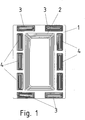
- a secondary winding 2 with first auxiliary windings 3 and auxiliary windings 4 oriented perpendicular thereto is shown on a carrier 1.
- This coil arrangement can be provided on the underbody of a vehicle, to which energy can be supplied from a primary conductor from the secondary winding 2 via an inductive coupling.
- the primary conductor is laid in the ground, and the vehicle can be moved on the ground by means of wheels.
- the primary conductor is laid elongated along the roadway in the ground and the vehicle draws energy while moving along the roadway, the secondary winding and primary conductor being inductively coupled only weakly.
- the primary conductor has a medium-frequency current applied to it, the secondary winding 2 having a capacitance connected in series or in parallel in such a way that the associated resonance frequency corresponds to the medium frequency.
- the center frequency has a value between 10 and 500 kHz, preferably between 15 and 100 kHz.
- the vehicle can be tracked by means of the auxiliary coils (3, 4), since different induction voltages result in the auxiliary coils (3, 4) if the primary conductor deviates from the plane containing the axis of symmetry of the coil arrangement and oriented perpendicular to the plane coil arrangement.
- auxiliary coils are provided in different positions and orientations on the outer circumference of the secondary winding, the incorrect orientation of the vehicle to the primary conductor can be seen.
- a primary winding is laid in the ground instead of the elongated primary conductor.
- an electric charging station can be provided.
- the vehicle can be positioned with its secondary winding over the primary winding and thus the energy storage device, for example a high-voltage accumulator, can be filled with energy.
- the primary winding is also designed as a winding with several turns, although there is an air gap between the primary winding and the secondary winding.
- the ground-laid primary winding is equipped with a coil core that has a center leg around which the primary winding is wound, and if such a coil core, preferably made of ferrite material, is also provided around the secondary winding, an air gap remains that weakens the inductive coupling .
- the mentioned capacity of the secondary winding is connected in the mentioned dimensioning.
- the secondary winding and preferably also the primary winding are designed as flat windings made of stranded wire, the stranded wire being composed of individual individual stranded wires that are electrically insulated from one another. This so-called HF litz wire enables losses to be reduced.
- the secondary winding is preferably designed as a flat winding, in particular as a rectangular flat winding.
- the auxiliary windings (3, 4) are designed by means of conductor tracks of a multi-layer printed circuit board provided as a carrier 1 and can thus be manufactured cost-effectively.
- the secondary winding 2 can also be implemented as a conductor track on such a printed circuit board, but in the case of high powers to be transmitted the above-mentioned design with HF litz wire is preferred.
- the secondary winding and the auxiliary coils (3, 4) are arranged in a corresponding plane.
- auxiliary coils (3, 4) there is also an arrangement of the auxiliary coils (3, 4) in a plane which is aligned parallel to that plane in which the secondary winding is provided.
- the two planar arrangements must then have a non-negligible distance, the plane of the auxiliary coils (3, 4) preferably being further apart from the primary winding than the plane of the secondary winding.
- an arrangement of the auxiliary coils (3, 4) can also be provided, a plane receiving the respective auxiliary coil 3 or 4 being oriented perpendicular to the plane in which the secondary winding is provided.
- the center of gravity of the auxiliary coils is preferably arranged in the plane of the secondary winding.
- the center of gravity of the respective auxiliary coil is also advantageous from the plane of the secondary winding, the center of gravity of the respective auxiliary coil (3, 4) being further away from the plane of the primary winding than the plane of the secondary winding.
- a first part of the auxiliary windings 3 is preferably aligned perpendicular to a second part of the auxiliary windings 4.
- the proportion of the main flux generated by the primary winding, which flows through the auxiliary coils, increases with increasing deviation from the symmetrical, i.e. optimal, position.
- the auxiliary coils are arranged outside the secondary winding and are thus located in the return flow area of the main flux generated by the primary winding when the primary winding is essentially the same or similar in size to the secondary winding.
- auxiliary coils are preferably provided, which are arranged in the corner areas of the secondary winding.
- Primary winding and secondary winding are preferably shaped identically or at least similar. They are preferably of the same size.
- the medium-frequency voltages induced in the auxiliary coils (3, 4) are fed to a respective signal processor 30, which in particular carries out filtering and analog-digital conversion of the signals.
- the thus digital signal streams are fed to a computer 31 which has a microcontroller and processes the signal streams further.
- the computer 31 is connected to a display means 32 for displaying the misorientation and to a parking device 33.
- This parking device enables automatic control of the optimal position, with the control of the vehicle's drives being carried out by a further computer in such a way that the optimal position is attainable.
- the parking device 33 can also only be designed as a parking aid, which supports the driver of the vehicle by means of acoustic and / or optical displays when moving into the optimal position.
- a trough is made in the floor so that the vehicle automatically rolls into the optimal position in a first direction with its front wheels. To achieve the optimal position in the transverse direction, only a slight back and forth movement of the vehicle is then necessary, with the steering wheels being aligned at the appropriate steering angle.
- the auxiliary coils are firmly connected to the primary winding instead of the secondary winding.
- a test signal alternating current or test pulse can be applied to the primary winding, so that a corresponding voltage is induced in the auxiliary winding.
- the voltage induced in response to the test pulse or test alternating current changes.
Landscapes
- Engineering & Computer Science (AREA)
- Power Engineering (AREA)
- Transportation (AREA)
- Mechanical Engineering (AREA)
- Computer Networks & Wireless Communication (AREA)
- Electric Propulsion And Braking For Vehicles (AREA)
- Current-Collector Devices For Electrically Propelled Vehicles (AREA)
Description
Die Erfindung betrifft ein System zur berührungslosen Energieübertragung an ein Fahrzeug.The invention relates to a system for contactless energy transmission to a vehicle.
Zur Positionierung von Fahrzeugen sind GPS-Systeme bekannt.GPS systems are known for positioning vehicles.
Aus der
Aus derFrom the
Aus derFrom the
Aus derFrom the
Aus derFrom the
Der Erfindung liegt daher die Aufgabe zugrunde, ein System zur berührungslosen Energieübertragung an ein Fahrzeug weiterzubilden.The invention is therefore based on the object of developing a system for contactless energy transmission to a vehicle.
Erfindungsgemäß wird die Aufgabe bei dem System zur berührungslosen Energieübertragung an ein Fahrzeug nach den in Anspruch 1 angegebenen Merkmalen gelöst.According to the invention, the object is achieved in the system for contactless energy transmission to a vehicle according to the features specified in
Von Vorteil ist dabei, dass mittels der Hilfswicklungen der bei einer Fehlpositionierung durch die Hilfswicklungen durchtretende magnetische Fluss detektierbar ist, insbesondere der in verschiedenen Hilfswicklungen verschieden starke Fluss. Dies ist insbesondere dann in einfacher Weise ausführbar, wenn die Hilfswicklungen symmetrisch zur Hauptspule, insbesondere Primärwicklung oder Sekundärwicklung, positioniert sind, so dass in der optimalen Lage gleich große Spannungen induziert werden.The advantage here is that the magnetic flux passing through the auxiliary windings in the event of incorrect positioning can be detected by means of the auxiliary windings, in particular the flux of different strengths in different auxiliary windings. This can be carried out in a simple manner in particular if the auxiliary windings are positioned symmetrically to the main coil, in particular the primary winding or secondary winding, so that voltages of the same size are induced in the optimal position.
Bei einer vorteilhaften Ausgestaltung ist der Primärleiter im der Sekundärwicklung im Boden gegenüberliegenden Bereich derart ausgeformt und/oder verlegt, dass eine Vorzugsrichtung ausgeprägt ist, insbesondere wobei der Primärleiter in diesem Bereich symmetrisch zu einer Symmetrieachse angeordnet und ausgebildet ist, insbesondere wobei die Symmetrieachse in Vorzugsrichtung ausgerichtet ist. Von Vorteil ist dabei, dass bei symmetrischer Anordnung der Hilfswicklungen die Abweichung von der optimalen Lage durch unterschiedlich starke induzierte Spannungen in den verschiedenen Hilfswicklungen erkennbar ist.In an advantageous embodiment, the primary conductor is shaped and / or laid in the area opposite the secondary winding in the bottom in such a way that a preferred direction is defined, in particular with the primary conductor in this area being arranged and designed symmetrically to an axis of symmetry, in particular with the axis of symmetry oriented in the preferred direction is. The advantage here is that with a symmetrical arrangement of the auxiliary windings, the deviation from the optimal position can be recognized by different strengths induced voltages in the various auxiliary windings.
Bei einer vorteilhaften Ausgestaltung sind die Hilfswicklungen derart angeordnet, dass das von dem mit Wechselstrom beaufschlagten Primärleiter erzeugte magnetische Wechselfeld in den Hilfswicklungen Spannung induziert, insbesondere zur Detektion der Abweichung des Fahrzeuges von derjenigen Position des Fahrzeugs, bei welcher Sekundärwicklung und Primärwicklung die stärkste induktive Kopplung aufweisen. Von Vorteil ist dabei, dass die Detektion in einfacher Weise ausführbar ist.In an advantageous embodiment, the auxiliary windings are arranged in such a way that the alternating magnetic field generated by the primary conductor charged with alternating current induces voltage in the auxiliary windings, in particular to detect the deviation of the vehicle from that position of the vehicle at which the secondary winding and primary winding have the strongest inductive coupling . The advantage here is that the detection can be carried out in a simple manner.
Bei einer vorteilhaften Ausgestaltung weist das Fahrzeug Räder auf, mit welchen es auf einem Boden verfahrbar ist, in oder auf welchem der Primärleiter angeordnet ist. Von Vorteil ist dabei, dass ein konstanter Abstand einhaltbar ist und somit trotz schwacher Kopplung durch resonante Übertragung ein hoher Wirkungsgrad erreichbar ist.In an advantageous embodiment, the vehicle has wheels with which it can be moved on a floor in or on which the primary conductor is arranged. The advantage here is that a constant distance can be maintained and thus a high degree of efficiency can be achieved despite weak coupling through resonant transmission.
Bei einer vorteilhaften Ausgestaltung sind Hilfswicklungen und die Sekundärwicklung beziehungsweise Primärwicklung parallel zueinander angeordnet, insbesondere in derselben Ebene. Von Vorteil ist dabei, dass eine besonders einfache Herstellung und Kalibrierung ermöglicht ist.In an advantageous embodiment, auxiliary windings and the secondary winding or primary winding are arranged parallel to one another, in particular in the same plane. The advantage here is that particularly simple production and calibration is made possible.
Bei einer vorteilhaften Ausgestaltung sind Hilfswicklungen und die Sekundärwicklung beziehungsweise Primärwicklung nicht parallel zueinander angeordnet, insbesondere wobei Hilfswicklungen und die Sekundärwicklung beziehungsweise Primärwicklung senkrecht zueinander angeordnet sind. Von Vorteil ist dabei, dass Die Spulenwicklungsachsen senkrecht zueinander ausgerichtet sind und somit die Hilfswicklungen auf der von der Primärwicklung abgewandten Seite der Sekundärwicklung angeordnet sind.In an advantageous embodiment, auxiliary windings and the secondary winding or primary winding are not arranged parallel to one another, in particular with auxiliary windings and the secondary winding or primary winding being arranged perpendicular to one another. The advantage here is that the coil winding axes are aligned perpendicular to one another and thus the auxiliary windings are arranged on the side of the secondary winding facing away from the primary winding.
Bei einer vorteilhaften Ausgestaltung sind zumindest eine erste und zweite Hilfswicklung gleichartig ausgeformt und bei gedachter Drehung um einen Winkelbetrag und gedachte Translation ineinander übergehen und/oder überführbar. Von Vorteil ist dabei, dass die beiden Hilfswicklungen zueinander verdreht angeordnet sind und somit entlang der jeweiligen Seite der Sekundärwicklung anordenbar sind. Insbesondere ist also die längere Seite der Hilfswicklung parallel zur längeren Seite der Sekundärwicklung anordenbar. Auf diese Weise ist eine höhere Empfindlichkeit erreichbar.In an advantageous embodiment, at least one first and second auxiliary winding are shaped identically and, with imaginary rotation by an angular amount and imaginary translation, merge into one another and / or can be converted. The advantage here is that the two auxiliary windings are arranged rotated with respect to one another and can thus be arranged along the respective side of the secondary winding. In particular, the longer side of the auxiliary winding can be arranged parallel to the longer side of the secondary winding. In this way, a higher sensitivity can be achieved.
Bei einer vorteilhaften Ausgestaltung ist zumindest eine erste Hilfswicklung in Fahrrichtung vor der Sekundärwicklung beziehungsweise Primärwicklung angeordnet und zumindest eine weitere erste Hilfswicklung in Fahrrichtung hinter der Sekundärwicklung beziehungsweise Primärwicklung angeordnet und zumindest eine zweite Hilfswicklung seitlich rechts neben der Sekundärwicklung beziehungsweise Primärwicklung angeordnet und zumindest eine weitere zweite Hilfswicklung seitlich links neben der Sekundärwicklung beziehungsweise Primärwicklung angeordnet. Von Vorteil ist dabei, dass bei jeder Fehlpositionierung des Fahrzeugs am Boden, also innerhalb der zweidimensionalen Verfahrebene des Fahrzeugs, eine Detektion mittels der Hilfswicklungen ermöglicht ist. Insbesondere sind die Differenzen der gegenüberliegenden Hilfswicklungen, also derjenigen Hilfswicklungen, welche mittels der Sekundärwicklung voneinander beabstandet sind, auswertbar und somit eine weiter erhöhte Empfindlichkeit erreichbar.In an advantageous embodiment, at least one first auxiliary winding is arranged in the direction of travel in front of the secondary winding or primary winding and at least one further first auxiliary winding is arranged in the direction of travel behind the secondary winding or primary winding and at least one second auxiliary winding is arranged to the right of the secondary winding or primary winding and at least one further second auxiliary winding arranged laterally to the left of the secondary winding or primary winding. The advantage here is that for everyone Incorrect positioning of the vehicle on the ground, that is, within the two-dimensional plane of movement of the vehicle, enables detection by means of the auxiliary windings. In particular, the differences between the opposing auxiliary windings, that is to say those auxiliary windings which are spaced apart from one another by means of the secondary winding, can be evaluated and thus a further increased sensitivity can be achieved.
Bei einer vorteilhaften Ausgestaltung ist zwischen zwei ersten Hilfswicklungen die Sekundärwicklung beziehungsweise Primärwicklung angeordnet, insbesondere wobei die Sekundärwicklung beziehungsweise Primärwicklung auch zwischen zwei weiteren Hilfswicklungen angeordnet ist, deren Verbindungslinie die Verbindungslinie der ersten Hilfswicklungen schneidet, insbesondere wobei die Verbindungslinien senkrecht zueinander stehen, insbesondere wobei die Verbindungslinien die jeweiligen Schwerpunkte der Hilfswicklungen schneiden. Von Vorteil ist dabei, dass wiederum die Erkennbarkeit von Verschiebungen des Fahrzeugs in beiden Dimensionen verbessert ist.In an advantageous embodiment, the secondary winding or primary winding is arranged between two first auxiliary windings, in particular wherein the secondary winding or primary winding is also arranged between two further auxiliary windings whose connecting line intersects the connecting line of the first auxiliary windings, in particular where the connecting lines are perpendicular to one another, in particular where the connecting lines intersect the respective centers of gravity of the auxiliary windings. The advantage here is that the recognizability of displacements of the vehicle in both dimensions is again improved.
Bei einer vorteilhaften Ausgestaltung wird der Primärleiter mit einem mittelfrequenten Strom beaufschlagt, wobei der Sekundärwicklung eine derartige Kapazität in Reihe oder parallel zugeschaltet ist, dass die zugehörige Resonanzfrequenz der Mittelfrequenz im Wesentlichen gleicht. Von Vorteil ist dabei, dass ein hoher Wirkungsgrad trotz Luftspalt und dadurch bewirkter schwacher Kopplung erreichbar ist.In an advantageous embodiment, a medium-frequency current is applied to the primary conductor, with such a capacitance being connected in series or in parallel to the secondary winding that the associated resonance frequency is essentially the same as the medium frequency. The advantage here is that a high degree of efficiency can be achieved despite the air gap and the resulting weak coupling.
Bei einer vorteilhaften Ausgestaltung sind die Hilfswicklungen im Rückflussbereich des vom Primärleiter erzeugten Feldes angeordnet. Von Vorteil ist dabei, dass der Rückflussbereich nutzbar ist zur Bestimmung der Abweichung.In an advantageous embodiment, the auxiliary windings are arranged in the return flow area of the field generated by the primary conductor. The advantage here is that the return flow area can be used to determine the deviation.
Bei einer vorteilhaften Ausgestaltung sind Sekundärwicklung und Primärwicklung parallel zueinander angeordnet sind. Von Vorteil ist dabei, dass eine verbesserte Kopplung und ein hoher Wirkungsgrad erreichbar sind, wobei die in den Hilfswicklungen induzierten Spannungen eineindeutig von der Verschiebung des Fahrzeugs aus der optimalen Position, also derjenigen Position mit der stärksten induktiven Kopplung, abhängen, insbesondere in jeder Verschiebungsrichtung.In an advantageous embodiment, the secondary winding and the primary winding are arranged parallel to one another. The advantage here is that improved coupling and high efficiency can be achieved, the voltages induced in the auxiliary windings being unambiguously dependent on the displacement of the vehicle from the optimal position, i.e. the position with the strongest inductive coupling, in particular in each direction of displacement.
Bei einer vorteilhaften Ausgestaltung sind die Hilfswicklungen am Fahrzeug angeordnet oder am Boden angeordnet. Von Vorteil ist dabei, dass bei Anordnung am Fahrzeug eine Auswerteelektronik am Fahrzeug vorzusehen ist und bei Anordnung im Boden die Auswerteelektronik im Boden vorsehbar ist, wobei allerdings eine Datenübertragung, beispielsweise durch hochfrequente Aufmodulation auf den in den Primärleiter eingeprägten mittelfrequenten Strom, vorgesehen werden muss.In an advantageous embodiment, the auxiliary windings are arranged on the vehicle or arranged on the floor. The advantage here is that when arranged on the vehicle a Evaluation electronics is to be provided on the vehicle and the evaluation electronics can be provided in the floor when arranged in the ground, although data transmission, for example by high-frequency modulation on the medium-frequency current impressed in the primary conductor, must be provided.
Bei einer vorteilhaften Ausgestaltung werden die Signale, insbesondere die induzierten Spannungen, der Hilfswicklungen einer Auswerteeinheit zugeführt, die mit einem Mittel zur Anzeige einer Fehlpositionierung der Sekundärwicklung zum Primärleiter verbunden ist und/oder mit einem Mittel zur Einparkhilfe oder mit einer Einparksteuerung. Von Vorteil ist dabei, dass ein automatisches Einparken, also Hinsteuern des Fahrzeuges auf die optimale Lage ermöglicht ist, also auf die Position mit der stärksten induktiven Kopplung zwischen Primärwicklung und Sekundärwicklung. Alternativ ist auch ein halbautomatisches Verfahren realisierbar, wie akustisches und/oder optisches Anzeigen der Abweichung als Einparkhilfe für den Fahrer des Fahrzeugs.In an advantageous embodiment, the signals, in particular the induced voltages, of the auxiliary windings are fed to an evaluation unit which is connected to a means for indicating incorrect positioning of the secondary winding relative to the primary conductor and / or to a means for parking assistance or parking control. The advantage here is that automatic parking, that is to say steering the vehicle to the optimal position, is possible, that is to say to the position with the strongest inductive coupling between the primary winding and the secondary winding. Alternatively, a semi-automatic method can also be implemented, such as acoustic and / or optical display of the deviation as a parking aid for the driver of the vehicle.
Bei einer vorteilhaften Ausgestaltung wird zumindest eine der Hilfswicklungen mit einem weiteren Stromanteil beaufschlagt, insbesondere mit einem hochfrequenten Stromanteil, insbesondere einem höher als die Mittelfrequenz frequenten Stromanteil, zur Datenübertragung,In an advantageous embodiment, at least one of the auxiliary windings has a further current component applied to it, in particular with a high-frequency current component, in particular a current component that is higher than the medium frequency, for data transmission,
insbesondere wobei der weitere Stromanteil eine Trägerfrequenz von mehr als einem Megahertz aufweist. Von Vorteil ist dabei, dass eine Datenübertragung in einfacher Weise ausführbar ist, wobei die Hilfswicklungen nicht nur der Detektion der Abweichung von der optimalen Position des Fahrzeugs, sondern als weitere Funktion das Senden und/oder Empfangen von Datenströmen ausführen.in particular wherein the further current component has a carrier frequency of more than one megahertz. The advantage here is that data transmission can be carried out in a simple manner, the auxiliary windings not only performing the detection of the deviation from the optimal position of the vehicle, but also sending and / or receiving data streams as a further function.
Bei einer vorteilhaften Ausgestaltung ist der zur Datenübertragung vorgesehenen, mit der Sekundärwicklung verbundenen Hilfswicklung eine mit dem Primärleiter fest verbundene Hilfswicklung zugeordnet, wobei der Abstand dieser Hilfswicklungen zueinander kleiner ist als der Abstand von der zur Datenübertragung vorgesehenen Hilfswicklung zu anderen Wicklungen, insbesondere in der optimalen Position, also derjenigen Position des Fahrzeugs, bei welcher die stärkste induktive Kopplung des Primärleiters zur Sekundärwicklung vorliegt. Von Vorteil ist dabei, dass somit über die beiden Hilfswicklungen eine Datenübertragung ermöglicht ist, insbesondere in einem Raumbereich um die optimale Position herum. Somit ist das Einparken automatisiert oder halbautomatisiert ausführbar.In an advantageous embodiment, the auxiliary winding provided for data transmission and connected to the secondary winding is assigned an auxiliary winding firmly connected to the primary conductor, the distance between these auxiliary windings being smaller than the distance from the auxiliary winding intended for data transmission to other windings, especially in the optimal position , i.e. the position of the vehicle at which the strongest inductive coupling of the primary conductor to the secondary winding is present. The advantage here is that data can be transmitted via the two auxiliary windings is made possible, especially in a space around the optimal position. Parking can therefore be carried out in an automated or semi-automated manner.
zumindest eine der Hilfswicklungen mit einem Stromanteil beaufschlagt, dessen Frequenzbereich außerhalb der vorgenannten Stromanteile, insbesondere also Mittelfrequenz beziehungsweise Frequenz zur Datenübertragung, angeordnet ist, wobei
aus der jeweiligen zugehörigen, an der Hilfswicklung anliegenden Spannung, welche zusammen mit dem Stromanteil erfasst wird, insbesondere mit der zugehörigen Phasenverschiebung, die Induktivität der jeweiligen Hilfswicklung bestimmt wird und daraus das Eindringen und/oder Vorhandensein von metallischen Fremdkörpern im Bereich zwischen Hilfswicklung und Primärleiter detektiert wird. Von Vorteil ist dabei, dass die Sicherheit weiter erhöhbar ist, da die Hilfswicklungen metallische Körper detektierbar machen. Denn metallische Körper werden bei der Leistungsübertragung von Wirbelströmen erhitzt und können unter Umständen somit Feuerbrand auslösen. Mittels der Detektion der Körper ist somit die Brandgefahr reduzierbar. Darüber hinaus ist sogar die Sorte des Metalls detektierbar, indem die frequenzabhängigen Materialkennlinien bestimmt werden. Daher ist in Weiterbildung sogar die Temperatur des Metallkörpers bestimmbar und bei Temperaturen über einer kritischen Temperatur, beispielsweise 80° Celsius oder 120° Celsius eine sicherheitsgerichtete Abschaltung der Energieübertragung ausführbar.at least one of the auxiliary windings has a current component applied to it, the frequency range of which is arranged outside the aforementioned current components, in particular medium frequency or frequency for data transmission, wherein
The inductance of the respective auxiliary winding is determined from the respective associated voltage applied to the auxiliary winding, which is recorded together with the current component, in particular with the associated phase shift, and from this the penetration and / or presence of metallic foreign bodies in the area between the auxiliary winding and the primary conductor is detected becomes. The advantage here is that the security can be further increased, since the auxiliary windings make metallic bodies detectable. This is because metallic bodies are heated by eddy currents during the power transmission and can thus trigger fire blight under certain circumstances. The risk of fire can thus be reduced by detecting the bodies. In addition, the type of metal can even be detected by determining the frequency-dependent material characteristics. Therefore, in a further development, even the temperature of the metal body can be determined and, at temperatures above a critical temperature, for example 80 ° Celsius or 120 ° Celsius, a safety-related shutdown of the energy transmission can be carried out.
Weitere Vorteile ergeben sich aus den Unteransprüchen. Die Erfindung ist nicht auf die Merkmalskombination der Ansprüche beschränkt. Für den Fachmann ergeben sich weitere sinnvolle Kombinationsmöglichkeiten im Rahmen der beigefügten Patentansprüche.Further advantages result from the subclaims. The invention is not restricted to the combination of features of the claims. For the person skilled in the art, further sensible combination possibilities arise within the scope of the attached patent claims.
Die Erfindung wird nun anhand von Abbildungen näher erläutert:
- In der
Figur 1 - In der
Figur 2 - In der
Figur 3
- In the
Figure 1 a coil arrangement according to the invention is shown in an oblique view. - In the
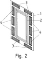
Figure 2 the coil arrangement according to the invention is shown in plan view. - In the
Figure 3 the associated signal processing is sketched schematically.
Wie in
Diese Spulenanordnung ist am Unterboden eines Fahrzeuges vorsehbar, dem über eine induktive Kopplung von einem Primärleiter aus der Sekundärwicklung 2 Energie zuführbar ist. Dabei ist der Primärleiter im Boden verlegt, wobei das Fahrzeug mittels Rädern auf dem Boden verfahrbar ist.This coil arrangement can be provided on the underbody of a vehicle, to which energy can be supplied from a primary conductor from the secondary winding 2 via an inductive coupling. The primary conductor is laid in the ground, and the vehicle can be moved on the ground by means of wheels.
In einer ersten Variante ist der Primärleiter langgestreckt entlang der Fahrbahn im Boden verlegt und das Fahrzeug entnimmt während der Bewegung entlang der Fahrbahn Energie, wobei Sekundärwicklung und Primärleiter induktiv nur schwach gekoppelt sind. Zur Erreichung eines hohen Wirkungsgrades ist der Primärleiter mit einem mittelfrequenten Strom beaufschlagt, wobei der Sekundärwicklung 2 eine Kapazität derart in Reihe oder parallel zugeschaltet ist, dass die zugehörige Resonanzfrequenz der Mittelfrequenz entspricht. Die Mittelfrequenz hat einen Wert zwischen 10 und 500 kHz, vorzugsweise zwischen 15 und 100 kHz.In a first variant, the primary conductor is laid elongated along the roadway in the ground and the vehicle draws energy while moving along the roadway, the secondary winding and primary conductor being inductively coupled only weakly. To achieve a high degree of efficiency, the primary conductor has a medium-frequency current applied to it, the secondary winding 2 having a capacitance connected in series or in parallel in such a way that the associated resonance frequency corresponds to the medium frequency. The center frequency has a value between 10 and 500 kHz, preferably between 15 and 100 kHz.
Mittels der Hilfsspulen (3, 4) ist eine Spurführung des Fahrzeuges realisierbar, da bei Abweichungen des Primärleiters aus der die Symmetrieachse der Spulenanordnung enthaltenden, senkrecht zur ebenen Spulenanordnung ausgerichteten Ebene sich unterschiedliche Induktionsspannungen in den Hilfsspulen (3, 4) ergeben.The vehicle can be tracked by means of the auxiliary coils (3, 4), since different induction voltages result in the auxiliary coils (3, 4) if the primary conductor deviates from the plane containing the axis of symmetry of the coil arrangement and oriented perpendicular to the plane coil arrangement.
Da am äußeren Umfang der Sekundärwicklung die Hilfsspulen in verschiedenen Positionen und Orientierungen vorgesehen sind, ist die Fehlorientierung des Fahrzeuges zum Primärleiter erkennbar.Since the auxiliary coils are provided in different positions and orientations on the outer circumference of the secondary winding, the incorrect orientation of the vehicle to the primary conductor can be seen.
In einer zweiten Variante ist statt des langgestreckten Primärleiters eine Primärwicklung im Boden verlegt. Auf diese Weise ist eine Elektrotankstelle bereitstellbar. Denn das Fahrzeug ist mit seiner Sekundärwicklung über der Primärwicklung positionierbar und somit der Energiespeicher, beispielsweise ein Hochvoltakkumulator, mit Energie auffüllbar. Hierzu ist die Primärwicklung ebenfalls als Wicklung mit mehreren Windungen ausgeführt, wobei allerdings zwischen der Primärwicklung und der Sekundärwicklung ein Luftspalt vorhanden ist. Auch wenn die bodenverlegte Primärwicklung mit einem Spulenkern ausgestattet ist, der einen Mittelschenkel aufweist, um den die Primärwicklung gewickelt ist, und wenn auch um die Sekundärwicklung ein solcher Spulenkern, vorzugsweise aus Ferritmaterial, vorgesehen wird, bleibt ein Luftspalt vorhanden, der die induktive Kopplung schwächt. Wiederum zur Erreichung eines hohen Wirkungsgrades ist die genannte Kapazität der Sekundärwicklung zugeschaltet in der genannten Dimensionierung.In a second variant, a primary winding is laid in the ground instead of the elongated primary conductor. In this way, an electric charging station can be provided. This is because the vehicle can be positioned with its secondary winding over the primary winding and thus the energy storage device, for example a high-voltage accumulator, can be filled with energy. For this purpose, the primary winding is also designed as a winding with several turns, although there is an air gap between the primary winding and the secondary winding. Even if the ground-laid primary winding is equipped with a coil core that has a center leg around which the primary winding is wound, and if such a coil core, preferably made of ferrite material, is also provided around the secondary winding, an air gap remains that weakens the inductive coupling . Again, in order to achieve a high degree of efficiency, the mentioned capacity of the secondary winding is connected in the mentioned dimensioning.
Die Sekundärwicklung und vorzugsweise auch die Primärwicklung sind als Flachwicklungen aus Litzenleitung ausgeführt, wobei die Litzenleitung aus einzelnen jeweils gegeneinander elektrisch isolierten Einzellitzendrähten zusammengesetzt ist. Diese sogenannte HF-Litze ermöglicht eine Verringerung von Verlusten.The secondary winding and preferably also the primary winding are designed as flat windings made of stranded wire, the stranded wire being composed of individual individual stranded wires that are electrically insulated from one another. This so-called HF litz wire enables losses to be reduced.
Die Sekundärwicklung ist vorzugsweise als Flachwicklung ausgeführt, insbesondere als rechteckförmige Flachwicklung.The secondary winding is preferably designed as a flat winding, in particular as a rectangular flat winding.
In einer weiteren erfindungsgemäßen Ausführungsform sind die Hilfswicklungen (3,4) mittels Leiterbahnen einer als Träger 1 vorgesehenen, mehrlagigen Leiterplatte ausgeführt und somit kostengünstig fertigbar. Die Sekundärwicklung 2 ist bei kleinen zu übertragenden Leistungen auch als Leiterbahn auf einer solchen Leiterplatte ausführbar, jedoch ist bei hohen zu übertragenden Leistungen die obengenannte Ausführung mit HF-Litze bevorzugt.In a further embodiment according to the invention, the auxiliary windings (3, 4) are designed by means of conductor tracks of a multi-layer printed circuit board provided as a
Wie in
In einem weiteren erfindungsgemäßen Ausführungsbeispiel ist auch eine Anordnung der Hilfsspulen (3, 4) in einer Ebene, die parallel zu derjenigen Ebene ausgerichtet ist, in welcher die Sekundärwicklung vorgesehen ist. Die beiden ebenen Anordnungen dürfen dann also einen nicht verschwindenden Abstand aufweisen, wobei bevorzugt die Ebene der Hilfsspulen (3, 4) weiter beabstandet ist von der Primärwicklung als die Ebene der Sekundärwicklung.In a further exemplary embodiment according to the invention, there is also an arrangement of the auxiliary coils (3, 4) in a plane which is aligned parallel to that plane in which the secondary winding is provided. The two planar arrangements must then have a non-negligible distance, the plane of the auxiliary coils (3, 4) preferably being further apart from the primary winding than the plane of the secondary winding.
In einem weiteren erfindungsgemäßen Ausführungsbeispiel ist auch eine Anordnung der Hilfsspulen (3, 4) vorsehbar, wobei eine die jeweilige Hilfsspule 3 oder 4 aufnehmende Ebene senkrecht zu derjenigen Ebene ausgerichtet ist, in welcher die Sekundärwicklung vorgesehen ist. Der Schwerpunkt der Hilfsspulen ist bevorzugt in der Ebene der Sekundärwicklung angeordnet. In einer weiteren Variante ist aber auch eine Beabstandung des Schwerpunktes der jeweiligen Hilfsspule von der Ebene der Sekundärwicklung vorteilhaft, wobei der Schwerpunkt der jeweiligen Hilfsspule (3, 4) weiter beabstandet ist von der Ebene der Primärwicklung als die Ebene der Sekundärwicklung.In a further exemplary embodiment according to the invention, an arrangement of the auxiliary coils (3, 4) can also be provided, a plane receiving the respective
Bei allen Varianten ist bevorzugt ein erster Teil der Hilfswicklungen 3 senkrecht zu einem zweiten Teil der Hilfswicklungen 4 ausgerichtet. Auf diese Weise sind relative Verschiebungen der Sekundärwicklung zur Primärwicklung, also Abweichungen aus der symmetrischen und somit optimalen Lage in zwei Richtungen besonders einfach und gut detektierbar. In der symmetrischen Lage ist der optimale Wirkungsgrad erreichbar.In all variants, a first part of the
Der Anteil des von der Primärwicklung erzeugten Hauptflusses, welcher die Hilfsspulen durchflutet, steigt mit zunehmender Abweichung aus der symmetrischen also optimalen Lage. Die Hilfsspulen sind außerhalb der Sekundärwicklung angeordnet und befinden sich somit im Rückflussbereich des von der Primärwicklung erzeugten Hauptflusses, wenn die Primärwicklung im Wesentlichen gleich oder ähnlich groß ist wie die Sekundärwicklung.The proportion of the main flux generated by the primary winding, which flows through the auxiliary coils, increases with increasing deviation from the symmetrical, i.e. optimal, position. The auxiliary coils are arranged outside the secondary winding and are thus located in the return flow area of the main flux generated by the primary winding when the primary winding is essentially the same or similar in size to the secondary winding.
Bevorzugt sind vier Hilfsspulen vorgesehen, die in den Eckbereichen der Sekundärwicklung angeordnet sind.Four auxiliary coils are preferably provided, which are arranged in the corner areas of the secondary winding.
Primärwicklung und Sekundärwicklung sind vorzugsweise gleichartig ausgeformt oder zumindest ähnlich. Bevorzugt sind sie gleichgroß ausgeführt.Primary winding and secondary winding are preferably shaped identically or at least similar. They are preferably of the same size.
Wie in
Der Rechner 31 ist mit einem Anzeigemittel 32 verbunden zur Anzeige der Fehlorientierung und mit einer Einparkvorrichtung 33. Mittels dieser Einparkvorrichtung ist ein selbsttätiges Ansteuern der optimalen Lage ermöglicht, wobei die Steuerung der Antriebe des Fahrzeugs von einem weiteren Rechner derart ausgeführt wird, dass die optimale Lage erreichbar ist. Alternativ ist auch die Einparkvorrichtung 33 auch nur als Einparkhilfe ausführbar, die dem Fahrer des Fahrzeuges durch akustische und/oder optische Anzeige beim Anfahren der optimalen Lage unterstützt.The
In einem weiteren erfindungsgemäßen Ausführungsbeispiel ist im Boden eine Mulde ausgeführt, so dass das Fahrzeug mit seinen Vorderrädern selbsttätig in die optimale Position in einer ersten Richtung einrollt. Zur Erreichung der optimalen Position in Querrichtung ist dann nur ein geringfügiges Hin- und Her Bewegen des Fahrzeuges notwendig, wobei die Lenkräder in entsprechende Lenkwinkel ausgerichtet werden.In a further exemplary embodiment according to the invention, a trough is made in the floor so that the vehicle automatically rolls into the optimal position in a first direction with its front wheels. To achieve the optimal position in the transverse direction, only a slight back and forth movement of the vehicle is then necessary, with the steering wheels being aligned at the appropriate steering angle.
In einem weiteren erfindungsgemäßen Ausführungsbeispiel sind die Hilfsspulen statt mit der Sekundärwicklung mit der Primärwicklung fest verbunden. Somit ist bei Nichtvorhandensein des Fahrzeugs die Primärwicklung mit einem Testsignalwechselstrom oder Testpuls beaufschlagbar, so dass eine entsprechende Spannung in der Hilfswicklung induziert wird. Sobald das Fahrzeug eintrifft und insbesondere mit seiner Sekundärwicklung samt zugehörigem Spulenkern, insbesondere Ferritkern, in den empfindlichen Bereich der Wicklungsanordnung eintritt, ändert sich die als Antwort auf den Testpuls oder Testwechselstrom induzierte Spannung. Durch Auswerten der in den jeweiligen Hilfswicklungen induzierten Spannungen ist es ermöglicht, die Abweichungen des Fahrzeugs von derjenigen Position anzuzeigen, in welcher die stärkste induktive Kopplung zwischen Sekundärwicklung und Primärwicklung auftritt. Außerdem ist es ermöglicht einer Regeleinheit die Spannungssignale zuzuführen, die die Position des Fahrzeuges auf diejenige Position hin regelt, bei der die in die zur Primärwicklung symmetrisch angeordneten Hilfswicklungen induzierten Spannungen sich gleichen. Somit ist ein Hinsteuern des Fahrzeugs zur optimalen Position ermöglicht.In a further exemplary embodiment according to the invention, the auxiliary coils are firmly connected to the primary winding instead of the secondary winding. Thus, when the vehicle is not present, a test signal alternating current or test pulse can be applied to the primary winding, so that a corresponding voltage is induced in the auxiliary winding. As soon as the vehicle arrives and in particular with its secondary winding including the associated coil core, in particular ferrite core, enters the sensitive area of the winding arrangement, the voltage induced in response to the test pulse or test alternating current changes. By evaluating the voltages induced in the respective auxiliary windings, it is possible to display the deviations of the vehicle from the position in which the strongest inductive coupling occurs between the secondary winding and the primary winding. In addition, it is possible to feed the voltage signals to a control unit, which controls the position of the vehicle towards that position in which the auxiliary windings arranged symmetrically with respect to the primary winding induced voltages are equal. This enables the vehicle to be steered towards the optimum position.
Bei symmetrischer Anordnung der Hilfswicklungen ist eine besonders einfache Bestimmung der Abweichung ermöglicht, da nur Summe oder Differenz der Spannungen von je zwei Hilfswicklungen zu bilden ist und Fehler verringert werden.With a symmetrical arrangement of the auxiliary windings, a particularly simple determination of the deviation is made possible since only the sum or difference of the voltages of two auxiliary windings has to be formed and errors are reduced.
- 1 Träger1 carrier
- 2 Sekundärwicklung2 secondary winding
- 3 Hilfswicklung3 auxiliary winding
- 4 Hilfswicklung4 auxiliary winding
- 30 Signalaufbereitung, insbesondere umfassend Filterung und Analog-Digital-Wandlung30 signal processing, in particular including filtering and analog-to-digital conversion
- 31 Rechner, insbesondere umfassend einen Mikrocontroller31 computers, in particular comprising a microcontroller
- 32 Anzeigemittel32 display means
- 33 Einparkvorrichtung33 Parking device
Claims (14)
- A system for contactless energy transmission to a vehicle,
wherein a primary conductor, in particular an underground primary conductor, can be inductively coupled to a secondary winding (2) of the vehicle,
wherein the primary conductor is configured as a primary winding,
wherein auxiliary windings (3, 4), in particular for the detection of deviations from the optimum orientation and/or positioning of the vehicle relative to the primary conductor, are provided, wherein the auxiliary windings (3, 4) are arranged exterior to the secondary winding (2) or primary winding,
in particular wherein the auxiliary windings (3, 4) form an arrangement with mirror symmetry or discrete rotational symmetry,
wherein the system comprises a means which is configured to act upon the primary conductor with a medium-frequency current,
characterised in that
the system comprises a further means which is configured to act upon at least one of the auxiliary windings (3, 4) with a current component whose frequency range is arranged outside of the frequency of the medium-frequency current, wherein the system comprises a computer (31) which is configured to determine the inductance of the respective auxiliary winding (3, 4) from the respective associated voltage present at the auxiliary winding (3, 4) and from the current component and to detect therefrom the penetration and/or presence of metallic foreign bodies in the region between auxiliary winding (3, 4) and primary conductor,
wherein the computer (31) is configured to determine the type of metal by means of frequency-dependent material characteristics and to determine the temperature of the respective metal and also to determine the temperature of the metal used for energy transmission, therefore the temperature of the primary conductor material and/or secondary winding material. - A system according to claim 1,
characterised in that
the primary conductor is formed and/or laid in such a manner in the ground region opposite the secondary winding (2) that there is a pronounced preferred direction, in particular wherein the primary conductor is in this region arranged and configured symmetrically to an axis of symmetry, in particular wherein the axis of symmetry is oriented in the preferred direction. - A system according to at least one of the preceding claims,
characterised in that
the auxiliary coils are arranged in such a manner that the magnetic alternating field generated by the primary conductor acted upon by alternating current induces voltage in the auxiliary windings (3, 4), in particular for detection of the deviation of the vehicle from that position of the vehicle in which secondary winding (2) and primary winding have the strongest inductive coupling. - A system according to at least one of the preceding claims,
characterised in that
the vehicle has wheels with which it can move on ground in or on which the primary conductor is arranged. - A system according to at least one of the preceding claims,
characterised in that
auxiliary windings (3, 4) and the secondary winding (2) or primary winding are arranged parallel to one another, in particular in the same plane. - A system according to at least one of the preceding claims,
characterised in that
auxiliary windings (3, 4) and the secondary winding (2) or primary winding are not arranged parallel to one another, in particular wherein auxiliary windings (3, 4) and the secondary winding (2) or primary winding are arranged perpendicularly to one another. - A system according to at least one of the preceding claims,
characterised in that
at least one first and second auxiliary winding (3, 4) are formed identically and merge into one another and/or are transferrable into one another upon notional rotation by an angular amount and notional translation. - A system according to at least one of the preceding claims,
characterised in that
at least one first auxiliary winding (3) is arranged upstream of the secondary winding (2) or primary winding in the direction of travel and
at least one further first auxiliary winding (3) is arranged downstream of the secondary winding (2) or primary winding in the direction of travel and
at least one second auxiliary winding (4) is arranged laterally alongside the secondary winding (2) or primary winding, to the right thereof and
at least one further second auxiliary winding (4) is arranged laterally alongside the secondary winding (2) or primary winding, to the left thereof. - A system according to at least one of the preceding claims,
characterised in that
the secondary winding (2) or primary winding is arranged between two first auxiliary windings (3, 4), in particular wherein the secondary winding (2) or primary winding is also arranged between two further auxiliary windings (3, 4) whose connecting line intersects the connecting line of the first auxiliary windings (3, 4), in particular wherein the connecting lines are perpendicular to one another, in particular wherein the connecting lines intersect the respective gravity centres of the auxiliary windings (3, 4). - A system according to at least one of the preceding claims,
characterised in that
a capacitor such that the associated resonance frequency substantially equals the medium frequency is connected in series or in parallel to the secondary winding (2). - A system according to at least one of the preceding claims,
characterised in that
the auxiliary windings (3, 4) are arranged in the backflow region of the field generated by the primary conductor. - A system according to at least one of the preceding claims,
characterised in that
secondary winding (2) and primary winding are arranged parallel to one another and/or in that
the auxiliary windings (3, 4) are arranged on the vehicle or on the ground. - A system according to at least one of the preceding claims,
characterised in that
the signals, in particular the induced voltages, of the auxiliary windings (3, 4) are fed to an evaluation unit which is connected to a means of displaying an incorrect positioning of the secondary winding (2) with respect to the primary conductor and/or connected to a means for parking assistance or connected to a parking control means. - A system according to at least one of the preceding claims,
characterised in that
at least one of the auxiliary windings (3, 4) is acted upon by a further current component, in particular by a high-frequency current component, in particular a current component with a frequency higher than the medium frequency, for data transmission,
in particular wherein the further current component has a carrier frequency of more than one megahertz,
and/orinthat
an auxiliary winding (3, 4) securely connected to the primary conductor is associated with the auxiliary winding (3, 4) provided for data transmission, wherein the spacing of these auxiliary windings (3, 4) from one another is smaller than the spacing of the auxiliary winding (3, 4) provided for data transmission from other windings, in particular in the optimum position, therefore that position of the vehicle in which there is the strongest inductive coupling of the primary conductor to the secondary winding (2).
Applications Claiming Priority (2)
| Application Number | Priority Date | Filing Date | Title |
|---|---|---|---|
| DE102010012356.0A DE102010012356B4 (en) | 2010-03-22 | 2010-03-22 | System for contactless energy transfer to a vehicle |
| PCT/EP2011/001017 WO2011116874A2 (en) | 2010-03-22 | 2011-03-02 | System for contactless transmission of energy to a vehicle |
Publications (2)
| Publication Number | Publication Date |
|---|---|
| EP2550174A2 EP2550174A2 (en) | 2013-01-30 |
| EP2550174B1 true EP2550174B1 (en) | 2021-05-12 |
Family
ID=44585421
Family Applications (1)
| Application Number | Title | Priority Date | Filing Date |
|---|---|---|---|
| EP11706758.7A Active EP2550174B1 (en) | 2010-03-22 | 2011-03-02 | System for contactless transmission of energy to a vehicle |
Country Status (3)
| Country | Link |
|---|---|
| EP (1) | EP2550174B1 (en) |
| DE (1) | DE102010012356B4 (en) |
| WO (1) | WO2011116874A2 (en) |
Families Citing this family (28)
| Publication number | Priority date | Publication date | Assignee | Title |
|---|---|---|---|---|
| DE102010050935B4 (en) * | 2010-03-25 | 2013-05-23 | Sew-Eurodrive Gmbh & Co. Kg | Device for the contactless transmission of energy to a vehicle |
| GB2500691B (en) * | 2012-03-30 | 2016-06-15 | Jaguar Land Rover Ltd | Charging system for a vehicle |
| EP2727759B1 (en) * | 2012-11-05 | 2015-01-14 | Alcatel Lucent | A method and device for a vehicle assist system |
| GB2508923A (en) * | 2012-12-17 | 2014-06-18 | Bombardier Transp Gmbh | Inductive power transfer system having inductive sensing array |
| GB2509080A (en) * | 2012-12-19 | 2014-06-25 | Bombardier Transp Gmbh | Inductive power transfer system having an additional receiving device |
| GB2517679A (en) | 2013-06-25 | 2015-03-04 | Bombardier Transp Gmbh | Object detection system and method for operating an object detection system |
| DE102013218471A1 (en) * | 2013-09-16 | 2015-03-19 | Robert Bosch Gmbh | Charging device, receiving device, system and method for inductively charging a rechargeable battery |
| DE102013110280A1 (en) | 2013-09-18 | 2015-03-19 | Paul Vahle Gmbh & Co. Kg | Positioning system for vehicles |
| DE102013227129B4 (en) | 2013-12-23 | 2016-01-14 | Continental Automotive Gmbh | Method for detecting a relative position, method for wireless charging of a vehicle, orientation signal receiver and inductive charging device |
| DE102014017544A1 (en) * | 2014-11-28 | 2016-06-02 | Sew-Eurodrive Gmbh & Co Kg | Method and system for inductive transmission of electrical energy to a vehicle |
| US9912172B2 (en) | 2015-01-14 | 2018-03-06 | Qualcomm Incorporated | Asymmetrically layered stacked coils and/or chamfered ferrite in wireless power transfer applications |
| FR3035831B1 (en) * | 2015-05-06 | 2018-09-07 | Renault S.A.S | POSITIONING DEVICE FOR ACCOMPANYING A VEHICLE WITH A CONTACTLESS LOAD TERMINAL. |
| EP3103674B1 (en) | 2015-06-12 | 2021-08-18 | Brusa Elektronik AG | Positioning system, method for positioning and system for inductive energy transmission with positioning system |
| US10340752B2 (en) * | 2015-06-23 | 2019-07-02 | Witricity Corporation | Systems, methods and apparatuses for guidance and alignment in electric vehicles wireless inductive charging systems |
| US10411524B2 (en) | 2015-06-23 | 2019-09-10 | Witricity Corporation | Systems, methods and apparatuses for guidance and alignment in electric vehicles wireless inductive charging systems |
| DE102015012368A1 (en) | 2015-09-19 | 2017-03-23 | Audi Ag | Method for determining a position information and arrangement comprising a motor vehicle and a stationary charging device to be approached describing a relative position of a motor vehicle relative to a stationary charging device to be approached |
| DE202016101808U1 (en) * | 2016-04-06 | 2016-04-27 | Fraunhofer-Gesellschaft zur Förderung der angewandten Forschung e.V. | System for the wireless transmission of energy and data |
| DE102017002960A1 (en) * | 2016-04-22 | 2017-10-26 | Sew-Eurodrive Gmbh & Co Kg | Method for determining a financial amount for a logistical service in a production facility and production facility with a vehicle for carrying out the method |
| WO2020002237A1 (en) * | 2018-06-29 | 2020-01-02 | Brusa Elektronik Ag | Vehicle charging system for charging an energy store arranged in a vehicle |
| DE102018213017A1 (en) * | 2018-08-03 | 2020-02-06 | Continental Automotive Gmbh | Method and device for determining the relative position of two coils to one another |
| DE102018217008A1 (en) * | 2018-10-04 | 2020-04-09 | Robert Bosch Gmbh | Device for wireless energy and / or data transmission |
| DE102018217074A1 (en) * | 2018-10-05 | 2020-04-09 | Continental Automotive Gmbh | Method and device for preparing energy transmission to a vehicle using an inductive charging system |
| DE102018009412A1 (en) | 2018-11-30 | 2019-05-16 | Daimler Ag | Device and method for determining a position of a Verbindungselments for loading a connecting element for charging an at least partially electrically driven vehicle |
| CN110435452B (en) * | 2019-08-20 | 2023-01-31 | 中兴新能源汽车有限责任公司 | Wireless charging guiding and positioning system and method, ground equipment and vehicle-mounted equipment |
| DE102019007172A1 (en) | 2019-10-16 | 2020-07-09 | Daimler Ag | Charging device and method for inductively charging an electrical energy store of an electrically operated motor vehicle |
| DE102021205102A1 (en) | 2021-05-19 | 2022-11-24 | Volkswagen Aktiengesellschaft | Method for inductive energy transfer between a vehicle and a supply network, vehicle, inductive charging device and system |
| WO2023194513A1 (en) * | 2022-04-07 | 2023-10-12 | Mahle International Gmbh | System for inductive energy transfer |
| DE102022203489A1 (en) * | 2022-04-07 | 2023-10-12 | Mahle International Gmbh | System for inductive energy transfer |
Citations (18)
| Publication number | Priority date | Publication date | Assignee | Title |
|---|---|---|---|---|
| US4742283A (en) | 1986-11-28 | 1988-05-03 | Inductran Corporation | Guidance system for inductively coupled electric vehicles |
| DE3916610A1 (en) | 1989-05-22 | 1989-12-07 | Goetting Hans Heinrich Jun | Device for data transmission and track guidance of vehicles |
| US5548214A (en) | 1991-11-21 | 1996-08-20 | Kaisei Engineer Co., Ltd. | Electromagnetic induction inspection apparatus and method employing frequency sweep of excitation current |
| EP0788212A2 (en) * | 1996-01-30 | 1997-08-06 | Sumitomo Wiring Systems, Ltd. | Connection system and connection method for an electric automotive vehicle |
| US5963035A (en) | 1997-08-21 | 1999-10-05 | Geophex, Ltd. | Electromagnetic induction spectroscopy for identifying hidden objects |
| US20020057075A1 (en) | 2000-09-04 | 2002-05-16 | Satoshi Takashige | Power feeding apparatus, transporter and transport system |
| DE10216422A1 (en) | 2002-04-12 | 2003-10-30 | Wampfler Ag | Device for inductive energy supply and guidance of a moving object |
| US20050094346A1 (en) | 2001-07-19 | 2005-05-05 | Senstronic | Method for detecting an object of conducting material and corresponding sensor |
| DE102006012562A1 (en) * | 2006-03-16 | 2007-09-27 | Sew-Eurodrive Gmbh & Co. Kg | Contact-less energy transmission system, has measuring unit with horizontal and vertical sensor coils for detecting lateral position change of vehicle, where distance between coils corresponds to distance of forward and return conductors |
| US20080164839A1 (en) | 2007-01-09 | 2008-07-10 | Sony Ericsson Mobile Communications Japan, Inc. | Noncontact charging device |
| US20080197957A1 (en) | 2007-02-20 | 2008-08-21 | Seiko Epson Corporation | Coil unit and electronic instrument |
| US20080297107A1 (en) * | 2007-05-28 | 2008-12-04 | Sony Ericsson Mobile Communications Japan, Inc. | Contactless power transferring coil unit, mobile terminal, power transmitting apparatus, and contactless power transferring system |
| US20090015197A1 (en) | 2007-07-13 | 2009-01-15 | Seiko Epson Corporation | Power transmission device and electronic instrument |
| WO2009040998A1 (en) | 2007-09-27 | 2009-04-02 | Panasonic Corporation | Contactless charger |
| JP2009089463A (en) | 2007-09-27 | 2009-04-23 | Panasonic Corp | Electronic equipment and charging system |
| EP2066001A2 (en) | 2007-11-30 | 2009-06-03 | Chun-Kil Jung | Contactless multi-charger system and controlling method thereof |
| WO2009081115A1 (en) | 2007-12-21 | 2009-07-02 | Amway (Europe) Limited | Inductive power transfer |
| JP2010051089A (en) | 2008-08-21 | 2010-03-04 | Fujitsu Ltd | Non-contacting power transmission system |
Family Cites Families (3)
| Publication number | Priority date | Publication date | Assignee | Title |
|---|---|---|---|---|
| JP3870315B2 (en) * | 2001-08-08 | 2007-01-17 | 株式会社日立製作所 | Mobile system |
| DE102007033654B4 (en) * | 2006-09-20 | 2019-08-01 | Sew-Eurodrive Gmbh & Co Kg | System with cart and base units |
| CN101809842A (en) * | 2007-09-27 | 2010-08-18 | 松下电器产业株式会社 | Electronic device, recharger and recharging system |
-
2010
- 2010-03-22 DE DE102010012356.0A patent/DE102010012356B4/en active Active
-
2011
- 2011-03-02 EP EP11706758.7A patent/EP2550174B1/en active Active
- 2011-03-02 WO PCT/EP2011/001017 patent/WO2011116874A2/en active Application Filing
Patent Citations (18)
| Publication number | Priority date | Publication date | Assignee | Title |
|---|---|---|---|---|
| US4742283A (en) | 1986-11-28 | 1988-05-03 | Inductran Corporation | Guidance system for inductively coupled electric vehicles |
| DE3916610A1 (en) | 1989-05-22 | 1989-12-07 | Goetting Hans Heinrich Jun | Device for data transmission and track guidance of vehicles |
| US5548214A (en) | 1991-11-21 | 1996-08-20 | Kaisei Engineer Co., Ltd. | Electromagnetic induction inspection apparatus and method employing frequency sweep of excitation current |
| EP0788212A2 (en) * | 1996-01-30 | 1997-08-06 | Sumitomo Wiring Systems, Ltd. | Connection system and connection method for an electric automotive vehicle |
| US5963035A (en) | 1997-08-21 | 1999-10-05 | Geophex, Ltd. | Electromagnetic induction spectroscopy for identifying hidden objects |
| US20020057075A1 (en) | 2000-09-04 | 2002-05-16 | Satoshi Takashige | Power feeding apparatus, transporter and transport system |
| US20050094346A1 (en) | 2001-07-19 | 2005-05-05 | Senstronic | Method for detecting an object of conducting material and corresponding sensor |
| DE10216422A1 (en) | 2002-04-12 | 2003-10-30 | Wampfler Ag | Device for inductive energy supply and guidance of a moving object |
| DE102006012562A1 (en) * | 2006-03-16 | 2007-09-27 | Sew-Eurodrive Gmbh & Co. Kg | Contact-less energy transmission system, has measuring unit with horizontal and vertical sensor coils for detecting lateral position change of vehicle, where distance between coils corresponds to distance of forward and return conductors |
| US20080164839A1 (en) | 2007-01-09 | 2008-07-10 | Sony Ericsson Mobile Communications Japan, Inc. | Noncontact charging device |
| US20080197957A1 (en) | 2007-02-20 | 2008-08-21 | Seiko Epson Corporation | Coil unit and electronic instrument |
| US20080297107A1 (en) * | 2007-05-28 | 2008-12-04 | Sony Ericsson Mobile Communications Japan, Inc. | Contactless power transferring coil unit, mobile terminal, power transmitting apparatus, and contactless power transferring system |
| US20090015197A1 (en) | 2007-07-13 | 2009-01-15 | Seiko Epson Corporation | Power transmission device and electronic instrument |
| WO2009040998A1 (en) | 2007-09-27 | 2009-04-02 | Panasonic Corporation | Contactless charger |
| JP2009089463A (en) | 2007-09-27 | 2009-04-23 | Panasonic Corp | Electronic equipment and charging system |
| EP2066001A2 (en) | 2007-11-30 | 2009-06-03 | Chun-Kil Jung | Contactless multi-charger system and controlling method thereof |
| WO2009081115A1 (en) | 2007-12-21 | 2009-07-02 | Amway (Europe) Limited | Inductive power transfer |
| JP2010051089A (en) | 2008-08-21 | 2010-03-04 | Fujitsu Ltd | Non-contacting power transmission system |
Non-Patent Citations (3)
| Title |
|---|
| "Gerthsen Physik", 1 January 2006, SPRINGER, article MESCHEDE DIETER: "7.1.4 WirbelstrSme", pages: 385, XP055895910 |
| SATO, F. ET AL.: "CONTACTLESS ENERGY TRANSMISSION TO MOBILE LOADS BY CLPS - TEST DRIVING OF AN EV WITH STARTER BATTERIES", IEEE TRANSACTIONS ON MAGNETICS, vol. 33, no. 5, September 1997 (1997-09-01), pages 4203 - 4205, XP011086420, DOI: 10.1109/20.619710 |
| SATO, F. ET AL.: "Stable Energy Transmission to Moving Loads utilizing New CLPS", IEEE TRANSACTIONS ON MAGNETICS, vol. 32, no. 5, September 1996 (1996-09-01), pages 5034 - 5036, XP000634212, DOI: 10.1109/20.539367 |
Also Published As
| Publication number | Publication date |
|---|---|
| WO2011116874A2 (en) | 2011-09-29 |
| DE102010012356B4 (en) | 2021-04-29 |
| EP2550174A2 (en) | 2013-01-30 |
| WO2011116874A3 (en) | 2011-12-22 |
| DE102010012356A1 (en) | 2011-09-22 |
Similar Documents
| Publication | Publication Date | Title |
|---|---|---|
| EP2550174B1 (en) | System for contactless transmission of energy to a vehicle | |
| EP2928044B1 (en) | System for the contactless transmission of energy from a primary winding to a vehicle comprising a secondary winding that can be inductively coupled to the primary winding, method for positioning a vehicle, method for determining a direction and position control device | |
| EP2782775B1 (en) | System for determining the position of objects which can move with respect to one another | |
| DE102012211151B4 (en) | Charging arrangement and method for inductive charging of an electrical energy store | |
| US11163313B2 (en) | Methods for positioning vehicles using electric road systems and vehicles operated using these methods | |
| WO2014041176A2 (en) | Metal foreign body-identification system for inductive energy transmission systems | |
| EP3398804B1 (en) | Inductive power transfer for transferring electric energy to a vehicle | |
| DE102014207253B4 (en) | Device for checking the presence of an electrically conductive body and charging device for inductively charging an electric vehicle | |
| EP2548088B1 (en) | System, method for determining the position of a vehicle within a system and method for creating an improved target path for a vehicle within a system | |
| EP2590836B1 (en) | Measuring a temperature during contactless transmission of energy | |
| WO2013143926A1 (en) | Device for inductive power transmission | |
| DE102014202747A1 (en) | Device for detecting a positional deviation of the passive coil relative to the primary coil of an inductive charging system for a vehicle and associated method | |
| WO2013143939A1 (en) | Device for inductively transmitting power | |
| WO2013189530A1 (en) | Detection coil assembly, energy transfer coil assembly and detection system for detecting electrically conductive foreign bodies | |
| WO2017092950A1 (en) | Method for operating a monitoring device for monitoring an inductive energy transmission device | |
| EP3046799B1 (en) | Method and system for operating a vehicle, in particular a vehicle that can be moved along a ground | |
| EP3028892B1 (en) | Method for positioning a motor vehicle in a loading position and motor vehicle | |
| DE102017214603B4 (en) | Method and device for detecting electrically conductive foreign bodies during inductive energy transfer | |
| DE102006012562B4 (en) | System and procedure | |
| EP3864427B1 (en) | Device for determining the position of an object movable relatively to a vehicle and a vehicle equipped with it | |
| DE102016212900A1 (en) | Method for operating a charging device for inductive energy transmission | |
| DE102021134196B3 (en) | Method for detecting at least a partial area of an area surrounding a motor vehicle with a sensor device, sensor device and motor vehicle | |
| DE102012023708A1 (en) | Method for determining relative position between mobile unit and transmitter, involves emitting wave train with certain wavelength by transmitter, where mobile unit comprises three receivers which are not arranged in straight line | |
| DE102012015200A1 (en) | Inductive proximity switch for detecting metallic targets in monitoring area, comprises transmitter coil that is cylindrical coil and receiving coil that is sheet-shaped coil, whose coil surface runs parallel to surface of transmitter coil | |
| EP3607408B1 (en) | Method for determining the position of a track-guided mobile element, and system |
Legal Events
| Date | Code | Title | Description |
|---|---|---|---|
| PUAI | Public reference made under article 153(3) epc to a published international application that has entered the european phase |
Free format text: ORIGINAL CODE: 0009012 |
|
| 17P | Request for examination filed |
Effective date: 20121022 |
|
| AK | Designated contracting states |
Kind code of ref document: A2 Designated state(s): AL AT BE BG CH CY CZ DE DK EE ES FI FR GB GR HR HU IE IS IT LI LT LU LV MC MK MT NL NO PL PT RO RS SE SI SK SM TR |
|
| DAX | Request for extension of the european patent (deleted) | ||
| STAA | Information on the status of an ep patent application or granted ep patent |
Free format text: STATUS: EXAMINATION IS IN PROGRESS |
|
| 17Q | First examination report despatched |
Effective date: 20180425 |
|
| REG | Reference to a national code |
Ref country code: DE Ref legal event code: R079 Ref document number: 502011017139 Country of ref document: DE Free format text: PREVIOUS MAIN CLASS: B60L0011180000 Ipc: B60L0053120000 |
|
| RIC1 | Information provided on ipc code assigned before grant |
Ipc: B60L 53/124 20190101ALI20190924BHEP Ipc: B60L 53/12 20190101AFI20190924BHEP Ipc: B60L 53/126 20190101ALI20190924BHEP |
|
| GRAP | Despatch of communication of intention to grant a patent |
Free format text: ORIGINAL CODE: EPIDOSNIGR1 |
|
| STAA | Information on the status of an ep patent application or granted ep patent |
Free format text: STATUS: GRANT OF PATENT IS INTENDED |
|
| INTG | Intention to grant announced |
Effective date: 20201103 |
|
| GRAS | Grant fee paid |
Free format text: ORIGINAL CODE: EPIDOSNIGR3 |
|
| GRAA | (expected) grant |
Free format text: ORIGINAL CODE: 0009210 |
|
| STAA | Information on the status of an ep patent application or granted ep patent |
Free format text: STATUS: THE PATENT HAS BEEN GRANTED |
|
| AK | Designated contracting states |
Kind code of ref document: B1 Designated state(s): AL AT BE BG CH CY CZ DE DK EE ES FI FR GB GR HR HU IE IS IT LI LT LU LV MC MK MT NL NO PL PT RO RS SE SI SK SM TR |
|
| REG | Reference to a national code |
Ref country code: GB Ref legal event code: FG4D Free format text: NOT ENGLISH |
|
| REG | Reference to a national code |
Ref country code: CH Ref legal event code: EP |
|
| REG | Reference to a national code |
Ref country code: DE Ref legal event code: R096 Ref document number: 502011017139 Country of ref document: DE |
|
| REG | Reference to a national code |
Ref country code: IE Ref legal event code: FG4D Free format text: LANGUAGE OF EP DOCUMENT: GERMAN |
|
| REG | Reference to a national code |
Ref country code: AT Ref legal event code: REF Ref document number: 1391975 Country of ref document: AT Kind code of ref document: T Effective date: 20210615 |
|
| REG | Reference to a national code |
Ref country code: LT Ref legal event code: MG9D |
|
| REG | Reference to a national code |
Ref country code: NL Ref legal event code: MP Effective date: 20210512 |
|
| PG25 | Lapsed in a contracting state [announced via postgrant information from national office to epo] |
Ref country code: FI Free format text: LAPSE BECAUSE OF FAILURE TO SUBMIT A TRANSLATION OF THE DESCRIPTION OR TO PAY THE FEE WITHIN THE PRESCRIBED TIME-LIMIT Effective date: 20210512 Ref country code: LT Free format text: LAPSE BECAUSE OF FAILURE TO SUBMIT A TRANSLATION OF THE DESCRIPTION OR TO PAY THE FEE WITHIN THE PRESCRIBED TIME-LIMIT Effective date: 20210512 Ref country code: HR Free format text: LAPSE BECAUSE OF FAILURE TO SUBMIT A TRANSLATION OF THE DESCRIPTION OR TO PAY THE FEE WITHIN THE PRESCRIBED TIME-LIMIT Effective date: 20210512 Ref country code: BG Free format text: LAPSE BECAUSE OF FAILURE TO SUBMIT A TRANSLATION OF THE DESCRIPTION OR TO PAY THE FEE WITHIN THE PRESCRIBED TIME-LIMIT Effective date: 20210812 |
|
| PG25 | Lapsed in a contracting state [announced via postgrant information from national office to epo] |
Ref country code: NO Free format text: LAPSE BECAUSE OF FAILURE TO SUBMIT A TRANSLATION OF THE DESCRIPTION OR TO PAY THE FEE WITHIN THE PRESCRIBED TIME-LIMIT Effective date: 20210812 Ref country code: PT Free format text: LAPSE BECAUSE OF FAILURE TO SUBMIT A TRANSLATION OF THE DESCRIPTION OR TO PAY THE FEE WITHIN THE PRESCRIBED TIME-LIMIT Effective date: 20210913 Ref country code: PL Free format text: LAPSE BECAUSE OF FAILURE TO SUBMIT A TRANSLATION OF THE DESCRIPTION OR TO PAY THE FEE WITHIN THE PRESCRIBED TIME-LIMIT Effective date: 20210512 Ref country code: ES Free format text: LAPSE BECAUSE OF FAILURE TO SUBMIT A TRANSLATION OF THE DESCRIPTION OR TO PAY THE FEE WITHIN THE PRESCRIBED TIME-LIMIT Effective date: 20210512 Ref country code: GR Free format text: LAPSE BECAUSE OF FAILURE TO SUBMIT A TRANSLATION OF THE DESCRIPTION OR TO PAY THE FEE WITHIN THE PRESCRIBED TIME-LIMIT Effective date: 20210813 Ref country code: IS Free format text: LAPSE BECAUSE OF FAILURE TO SUBMIT A TRANSLATION OF THE DESCRIPTION OR TO PAY THE FEE WITHIN THE PRESCRIBED TIME-LIMIT Effective date: 20210912 Ref country code: LV Free format text: LAPSE BECAUSE OF FAILURE TO SUBMIT A TRANSLATION OF THE DESCRIPTION OR TO PAY THE FEE WITHIN THE PRESCRIBED TIME-LIMIT Effective date: 20210512 Ref country code: RS Free format text: LAPSE BECAUSE OF FAILURE TO SUBMIT A TRANSLATION OF THE DESCRIPTION OR TO PAY THE FEE WITHIN THE PRESCRIBED TIME-LIMIT Effective date: 20210512 Ref country code: SE Free format text: LAPSE BECAUSE OF FAILURE TO SUBMIT A TRANSLATION OF THE DESCRIPTION OR TO PAY THE FEE WITHIN THE PRESCRIBED TIME-LIMIT Effective date: 20210512 |
|
| PG25 | Lapsed in a contracting state [announced via postgrant information from national office to epo] |
Ref country code: NL Free format text: LAPSE BECAUSE OF FAILURE TO SUBMIT A TRANSLATION OF THE DESCRIPTION OR TO PAY THE FEE WITHIN THE PRESCRIBED TIME-LIMIT Effective date: 20210512 |
|
| PG25 | Lapsed in a contracting state [announced via postgrant information from national office to epo] |
Ref country code: RO Free format text: LAPSE BECAUSE OF FAILURE TO SUBMIT A TRANSLATION OF THE DESCRIPTION OR TO PAY THE FEE WITHIN THE PRESCRIBED TIME-LIMIT Effective date: 20210512 Ref country code: SK Free format text: LAPSE BECAUSE OF FAILURE TO SUBMIT A TRANSLATION OF THE DESCRIPTION OR TO PAY THE FEE WITHIN THE PRESCRIBED TIME-LIMIT Effective date: 20210512 Ref country code: SM Free format text: LAPSE BECAUSE OF FAILURE TO SUBMIT A TRANSLATION OF THE DESCRIPTION OR TO PAY THE FEE WITHIN THE PRESCRIBED TIME-LIMIT Effective date: 20210512 Ref country code: DK Free format text: LAPSE BECAUSE OF FAILURE TO SUBMIT A TRANSLATION OF THE DESCRIPTION OR TO PAY THE FEE WITHIN THE PRESCRIBED TIME-LIMIT Effective date: 20210512 Ref country code: CZ Free format text: LAPSE BECAUSE OF FAILURE TO SUBMIT A TRANSLATION OF THE DESCRIPTION OR TO PAY THE FEE WITHIN THE PRESCRIBED TIME-LIMIT Effective date: 20210512 Ref country code: EE Free format text: LAPSE BECAUSE OF FAILURE TO SUBMIT A TRANSLATION OF THE DESCRIPTION OR TO PAY THE FEE WITHIN THE PRESCRIBED TIME-LIMIT Effective date: 20210512 |
|
| REG | Reference to a national code |
Ref country code: DE Ref legal event code: R026 Ref document number: 502011017139 Country of ref document: DE |
|
| PLBI | Opposition filed |
Free format text: ORIGINAL CODE: 0009260 |
|
| PLAX | Notice of opposition and request to file observation + time limit sent |
Free format text: ORIGINAL CODE: EPIDOSNOBS2 |
|
| 26 | Opposition filed |
Opponent name: IPT TECHNOLOGY GMBH Effective date: 20220214 |
|
| PG25 | Lapsed in a contracting state [announced via postgrant information from national office to epo] |
Ref country code: IS Free format text: LAPSE BECAUSE OF FAILURE TO SUBMIT A TRANSLATION OF THE DESCRIPTION OR TO PAY THE FEE WITHIN THE PRESCRIBED TIME-LIMIT Effective date: 20210912 Ref country code: AL Free format text: LAPSE BECAUSE OF FAILURE TO SUBMIT A TRANSLATION OF THE DESCRIPTION OR TO PAY THE FEE WITHIN THE PRESCRIBED TIME-LIMIT Effective date: 20210512 |
|
| PLBB | Reply of patent proprietor to notice(s) of opposition received |
Free format text: ORIGINAL CODE: EPIDOSNOBS3 |
|
| PG25 | Lapsed in a contracting state [announced via postgrant information from national office to epo] |
Ref country code: IT Free format text: LAPSE BECAUSE OF FAILURE TO SUBMIT A TRANSLATION OF THE DESCRIPTION OR TO PAY THE FEE WITHIN THE PRESCRIBED TIME-LIMIT Effective date: 20210512 |
|
| PG25 | Lapsed in a contracting state [announced via postgrant information from national office to epo] |
Ref country code: MC Free format text: LAPSE BECAUSE OF FAILURE TO SUBMIT A TRANSLATION OF THE DESCRIPTION OR TO PAY THE FEE WITHIN THE PRESCRIBED TIME-LIMIT Effective date: 20210512 |
|
| REG | Reference to a national code |
Ref country code: CH Ref legal event code: PL |
|
| GBPC | Gb: european patent ceased through non-payment of renewal fee |
Effective date: 20220302 |
|
| REG | Reference to a national code |
Ref country code: BE Ref legal event code: MM Effective date: 20220331 |
|
| PG25 | Lapsed in a contracting state [announced via postgrant information from national office to epo] |
Ref country code: LU Free format text: LAPSE BECAUSE OF NON-PAYMENT OF DUE FEES Effective date: 20220302 Ref country code: LI Free format text: LAPSE BECAUSE OF NON-PAYMENT OF DUE FEES Effective date: 20220331 Ref country code: IE Free format text: LAPSE BECAUSE OF NON-PAYMENT OF DUE FEES Effective date: 20220302 Ref country code: GB Free format text: LAPSE BECAUSE OF NON-PAYMENT OF DUE FEES Effective date: 20220302 Ref country code: FR Free format text: LAPSE BECAUSE OF NON-PAYMENT OF DUE FEES Effective date: 20220331 Ref country code: CH Free format text: LAPSE BECAUSE OF NON-PAYMENT OF DUE FEES Effective date: 20220331 |
|
| PG25 | Lapsed in a contracting state [announced via postgrant information from national office to epo] |
Ref country code: BE Free format text: LAPSE BECAUSE OF NON-PAYMENT OF DUE FEES Effective date: 20220331 |
|
| PLAB | Opposition data, opponent's data or that of the opponent's representative modified |
Free format text: ORIGINAL CODE: 0009299OPPO |
|
| R26 | Opposition filed (corrected) |
Opponent name: IPT TECHNOLOGY GMBH Effective date: 20220214 |
|
| REG | Reference to a national code |
Ref country code: AT Ref legal event code: MM01 Ref document number: 1391975 Country of ref document: AT Kind code of ref document: T Effective date: 20220302 |
|
| PG25 | Lapsed in a contracting state [announced via postgrant information from national office to epo] |
Ref country code: AT Free format text: LAPSE BECAUSE OF NON-PAYMENT OF DUE FEES Effective date: 20220302 |
|
| PG25 | Lapsed in a contracting state [announced via postgrant information from national office to epo] |
Ref country code: HU Free format text: LAPSE BECAUSE OF FAILURE TO SUBMIT A TRANSLATION OF THE DESCRIPTION OR TO PAY THE FEE WITHIN THE PRESCRIBED TIME-LIMIT; INVALID AB INITIO Effective date: 20110302 |
|
| PG25 | Lapsed in a contracting state [announced via postgrant information from national office to epo] |
Ref country code: MK Free format text: LAPSE BECAUSE OF FAILURE TO SUBMIT A TRANSLATION OF THE DESCRIPTION OR TO PAY THE FEE WITHIN THE PRESCRIBED TIME-LIMIT Effective date: 20210512 Ref country code: CY Free format text: LAPSE BECAUSE OF FAILURE TO SUBMIT A TRANSLATION OF THE DESCRIPTION OR TO PAY THE FEE WITHIN THE PRESCRIBED TIME-LIMIT Effective date: 20210512 |
|
| PGFP | Annual fee paid to national office [announced via postgrant information from national office to epo] |
Ref country code: DE Payment date: 20240331 Year of fee payment: 14 |