EP2548805A2 - Fan motor cooling and method - Google Patents
Fan motor cooling and method Download PDFInfo
- Publication number
- EP2548805A2 EP2548805A2 EP12176992A EP12176992A EP2548805A2 EP 2548805 A2 EP2548805 A2 EP 2548805A2 EP 12176992 A EP12176992 A EP 12176992A EP 12176992 A EP12176992 A EP 12176992A EP 2548805 A2 EP2548805 A2 EP 2548805A2
- Authority
- EP
- European Patent Office
- Prior art keywords
- flow path
- air
- fan assembly
- motor
- flange
- Prior art date
- Legal status (The legal status is an assumption and is not a legal conclusion. Google has not performed a legal analysis and makes no representation as to the accuracy of the status listed.)
- Granted
Links
- 238000001816 cooling Methods 0.000 title claims description 11
- 238000000034 method Methods 0.000 title claims description 7
- 239000008186 active pharmaceutical agent Substances 0.000 abstract 1
- 238000004378 air conditioning Methods 0.000 description 2
- 230000008901 benefit Effects 0.000 description 2
- 238000012986 modification Methods 0.000 description 1
- 230000004048 modification Effects 0.000 description 1
- 238000011144 upstream manufacturing Methods 0.000 description 1
Images


Classifications
-
- B—PERFORMING OPERATIONS; TRANSPORTING
- B64—AIRCRAFT; AVIATION; COSMONAUTICS
- B64D—EQUIPMENT FOR FITTING IN OR TO AIRCRAFT; FLIGHT SUITS; PARACHUTES; ARRANGEMENT OR MOUNTING OF POWER PLANTS OR PROPULSION TRANSMISSIONS IN AIRCRAFT
- B64D33/00—Arrangements in aircraft of power plant parts or auxiliaries not otherwise provided for
- B64D33/08—Arrangements in aircraft of power plant parts or auxiliaries not otherwise provided for of power plant cooling systems
-
- F—MECHANICAL ENGINEERING; LIGHTING; HEATING; WEAPONS; BLASTING
- F04—POSITIVE - DISPLACEMENT MACHINES FOR LIQUIDS; PUMPS FOR LIQUIDS OR ELASTIC FLUIDS
- F04D—NON-POSITIVE-DISPLACEMENT PUMPS
- F04D19/00—Axial-flow pumps
-
- F—MECHANICAL ENGINEERING; LIGHTING; HEATING; WEAPONS; BLASTING
- F04—POSITIVE - DISPLACEMENT MACHINES FOR LIQUIDS; PUMPS FOR LIQUIDS OR ELASTIC FLUIDS
- F04D—NON-POSITIVE-DISPLACEMENT PUMPS
- F04D25/00—Pumping installations or systems
- F04D25/02—Units comprising pumps and their driving means
- F04D25/06—Units comprising pumps and their driving means the pump being electrically driven
-
- F—MECHANICAL ENGINEERING; LIGHTING; HEATING; WEAPONS; BLASTING
- F04—POSITIVE - DISPLACEMENT MACHINES FOR LIQUIDS; PUMPS FOR LIQUIDS OR ELASTIC FLUIDS
- F04D—NON-POSITIVE-DISPLACEMENT PUMPS
- F04D29/00—Details, component parts, or accessories
- F04D29/58—Cooling; Heating; Diminishing heat transfer
- F04D29/5806—Cooling the drive system
Definitions
- This disclosure relates generally to cooling a component of a fan and, more particularly, to cooling a fan motor.
- Fans are often used to move air. Fans may, for example, move air through heat exchangers of air conditioning packs on aircraft. The air moved by the fans cools the heat exchangers. Such fans within aircraft are often ram air fans. When the aircraft is stationary, motors are typically used to rotate the rotors of the ram air fans. Thermal energy can build up within components of fans and cause damage as is known. Motors of ram air fans are particularly prone to such thermal energy build-up.
- ram air fan designs rely on a radial blower to pull a flow of cooling air through the motor.
- the radial blower redirects air that has been used to cool the motor radially away from a rotational axis of the fan and into a primary flow path of air through the ram air fan.
- the flow from the radial blower distorts flow of air along the primary flow path, which makes the ram air fan less efficient.
- the radial blower is inefficient and is also heavy.
- An example fan assembly impeller moves air along a secondary flow path when driven by a motor.
- the motor also drives a fan rotor to move air along a primary flow path of the fan assembly. Air moving along the primary flow path moves in a first direction. Air moving along the secondary flow path moves in a second direction opposite the first direction.
- An example fan shroud communicates air used to cool a motor into a primary flow path of a fan assembly.
- the shroud communicates the air into the primary flow path so that the flow of air is at least partially aligned with air moving through the primary flow path of the fan assembly.
- An example fan assembly includes a fan rotor that is rotatable about an axis.
- the fan assembly also includes an impeller and a motor positioned axially between the impeller and the rotor.
- the motor rotatably drives the impeller and the fan rotor.
- the fan rotor moves air from the fan rotor axially toward the impeller along a primary flow path.
- the impeller moves air from the impeller axially toward the fan rotor along a secondary flow path.
- a flow directing shroud defines an annular channel that directs air from the secondary flow path into the primary flow path.
- An example method of cooling a motor of a fan assembly includes rotating a fan rotor with a motor, and also rotating an impeller with the motor. The method moves air through the motor using the impeller.
- the motor is located axially between the fan rotor and the impeller.
- an example fan assembly 10 includes a fan rotor 12, a motor 14, and an impeller 16.
- the motor 14 rotates a shaft 18 about an axis X to rotate the fan rotor 12 and the impeller 16.
- the fan assembly 10 includes a primary flow path 24 bounded by a radially inner housing 26 and a radially outer housing 28.
- the primary flow path 24 is an annular flow path.
- the example fan assembly 10 is a ram air fan assembly. Rotating the fan rotor 12 draws air into the primary flow path 24 of the fan assembly 10. The air moves through the primary flow path 24 from the fan rotor 12 toward the impeller 16 in a direction Dp. Air moving through the primary flow path 24 moves past the motor 14 and impeller 16 and is exhausted from the fan assembly 10 at an exhaust section 30. The exhausted air cools heat exchangers 32 of aircraft air conditioning packs 34, for example.
- the fan assembly 10 includes a secondary flow path 36 established radially inside the inner housing 26 of the fan assembly 10.
- a cooling inlet duct 38 extends radially from the secondary flow path 36 across the primary flow path 24.
- the cooling inlet duct 38 communicates air to the secondary flow path 36.
- the cooling inlet duct 38 forms a portion of the secondary flow path 36 in some examples.
- Rotating the impeller 16 draws air through an inlet 40 and into the secondary flow path 36. Air moves along the secondary flow path 36 in a direction Ds. Air moving along the secondary flow path 36 moves through the motor 14 and carries thermal energy away from the motor 14.
- a shroud 44 receives air that has been communicated along the secondary flow path 36 through the motor 14.
- the shroud 44 communicates the received air into the primary flow path.
- the direction Ds is opposite the direction Dp.
- the impeller 16 is connected directly to the shaft 18, which is also coupled to the fan rotor 12.
- the motor 14 rotates the fan rotor 12
- the motor 14 is also rotating the impeller 16 to draw a flow of cooling air through the motor 14.
- the impeller 16 is mounted to a first axial end portion 46 of the shaft 18 and secured with a mechanical fastener 48, such as a nut.
- a mechanical fastener 48 such as a nut.
- the example fan rotor 12 is mounted to a second axial end portion 50 of the shaft 18.
- the shroud 44 of the example fan assembly 10 is upstream from the fan rotor 12 relative the direction Dp of flow through the primary flow path 24.
- the shroud 44 is configured to redirect air received from the motor 14. Notably, in this example, the shroud 44 redirects air moving in the direction Ds so that the air at least partially moves in the direction Dp. The shroud 44 thus does not communicate air directly into the primary flow path 24 in an exclusively radial direction.
- the example shroud 44 includes a first flange 52 and a second flange 54 that establish an annular channel 56 used to redirect air that has been communicated along the secondary flow path 36 into the primary flow path 24.
- the annular channel 56 is tilted relative to the axis of the fan assembly 10 at an angle ⁇ , which is less than 90 degrees in this example.
- the annular channel 56 is thus at least partially axially aligned with the primary flow path 24.
- the flow through the channel 56 has a component of direction along the primary flow path 24.
- the shroud 44 and particularly the annular channel 56, directs air at a radially inner base 58 of the fan rotor 12. Introducing flow in a direction having at least some axial component helps lessen distortion of air entering the fan assembly 10.
- the first flange 52 extends from a first flange base 64 to a first flange tip 66.
- the second flange 54 extends from a second flange base 68 to a second flange tip 70.
- the first flange base 64 is radially outside the second flange base 68
- the first flange tip 66 is radially inside the second flange tip 70.
- first flange 52 and the second flange 54 generally extend axially away from the motor 14. That is, the first flange base 64 is axially closer to the motor 14 than the first flange tip 66. Similarly, the second flange base 68 is axially closer to the motor 14 than the second flange tip 70. In other examples, other configurations of flanges may be used.
- features of the disclosed examples include moving air through a motor of a fan assembly using an impeller.
- the air cools the motor.
- Another feature of this invention includes directing air that has moved through the motor into a primary flow path of a fan. The air is directed in an at least partially axial direction to lessen disturbances and turbulence of air entering the fan assembly.
Landscapes
- Engineering & Computer Science (AREA)
- Mechanical Engineering (AREA)
- General Engineering & Computer Science (AREA)
- Physics & Mathematics (AREA)
- Thermal Sciences (AREA)
- Chemical & Material Sciences (AREA)
- Combustion & Propulsion (AREA)
- Aviation & Aerospace Engineering (AREA)
- Structures Of Non-Positive Displacement Pumps (AREA)
- Motor Or Generator Cooling System (AREA)
Abstract
Description
- This disclosure relates generally to cooling a component of a fan and, more particularly, to cooling a fan motor.
- Fans are often used to move air. Fans may, for example, move air through heat exchangers of air conditioning packs on aircraft. The air moved by the fans cools the heat exchangers. Such fans within aircraft are often ram air fans. When the aircraft is stationary, motors are typically used to rotate the rotors of the ram air fans. Thermal energy can build up within components of fans and cause damage as is known. Motors of ram air fans are particularly prone to such thermal energy build-up.
- Some prior art ram air fan designs rely on a radial blower to pull a flow of cooling air through the motor. The radial blower redirects air that has been used to cool the motor radially away from a rotational axis of the fan and into a primary flow path of air through the ram air fan. The flow from the radial blower distorts flow of air along the primary flow path, which makes the ram air fan less efficient. The radial blower is inefficient and is also heavy.
- An example fan assembly impeller moves air along a secondary flow path when driven by a motor. The motor also drives a fan rotor to move air along a primary flow path of the fan assembly. Air moving along the primary flow path moves in a first direction. Air moving along the secondary flow path moves in a second direction opposite the first direction.
- An example fan shroud communicates air used to cool a motor into a primary flow path of a fan assembly. The shroud communicates the air into the primary flow path so that the flow of air is at least partially aligned with air moving through the primary flow path of the fan assembly.
- An example fan assembly includes a fan rotor that is rotatable about an axis. The fan assembly also includes an impeller and a motor positioned axially between the impeller and the rotor. The motor rotatably drives the impeller and the fan rotor. The fan rotor moves air from the fan rotor axially toward the impeller along a primary flow path. The impeller moves air from the impeller axially toward the fan rotor along a secondary flow path. A flow directing shroud defines an annular channel that directs air from the secondary flow path into the primary flow path.
- An example method of cooling a motor of a fan assembly includes rotating a fan rotor with a motor, and also rotating an impeller with the motor. The method moves air through the motor using the impeller. The motor is located axially between the fan rotor and the impeller.
- The various features and advantages of the disclosed examples will become apparent to those skilled in the art from the detailed description. The figures that accompany the detailed description can be briefly described as follows:
-
Figure 1 shows a section view of an example fan assembly. -
Figure 2 shows a simplified section view of theFigure 1 fan assembly at line 2-2 inFigure 1 . -
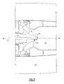
Figure 3 shows a close-up view of an impeller within theFigure 1 fan assembly. -
Figure 4 shows a close-up view of a shroud within theFigure 1 fan assembly. - Referring to
Figures 1 and 2 , anexample fan assembly 10 includes afan rotor 12, amotor 14, and animpeller 16. Themotor 14 rotates ashaft 18 about an axis X to rotate thefan rotor 12 and theimpeller 16. - The
fan assembly 10 includes aprimary flow path 24 bounded by a radiallyinner housing 26 and a radiallyouter housing 28. Theprimary flow path 24 is an annular flow path. - The
example fan assembly 10 is a ram air fan assembly. Rotating thefan rotor 12 draws air into theprimary flow path 24 of thefan assembly 10. The air moves through theprimary flow path 24 from thefan rotor 12 toward theimpeller 16 in a direction Dp. Air moving through theprimary flow path 24 moves past themotor 14 andimpeller 16 and is exhausted from thefan assembly 10 at anexhaust section 30. The exhausted air coolsheat exchangers 32 of aircraftair conditioning packs 34, for example. - The
fan assembly 10 includes asecondary flow path 36 established radially inside theinner housing 26 of thefan assembly 10. Acooling inlet duct 38 extends radially from thesecondary flow path 36 across theprimary flow path 24. Thecooling inlet duct 38 communicates air to thesecondary flow path 36. Thecooling inlet duct 38 forms a portion of thesecondary flow path 36 in some examples. - Rotating the
impeller 16 draws air through aninlet 40 and into thesecondary flow path 36. Air moves along thesecondary flow path 36 in a direction Ds. Air moving along thesecondary flow path 36 moves through themotor 14 and carries thermal energy away from themotor 14. - A
shroud 44 receives air that has been communicated along thesecondary flow path 36 through themotor 14. Theshroud 44 communicates the received air into the primary flow path. Notably, the direction Ds is opposite the direction Dp. - Referring to
Figures 3 and4 with continuing reference toFigures 1 and 2 , theimpeller 16 is connected directly to theshaft 18, which is also coupled to thefan rotor 12. Thus, whenever themotor 14 rotates thefan rotor 12, themotor 14 is also rotating theimpeller 16 to draw a flow of cooling air through themotor 14. - In this example, the
impeller 16 is mounted to a firstaxial end portion 46 of theshaft 18 and secured with amechanical fastener 48, such as a nut. A person having skill in this art and the benefit of this disclosure would understand how to design an impeller suitable for moving air along a path when rotated. - The
example fan rotor 12 is mounted to a secondaxial end portion 50 of theshaft 18. Theshroud 44 of theexample fan assembly 10 is upstream from thefan rotor 12 relative the direction Dp of flow through theprimary flow path 24. - The
shroud 44 is configured to redirect air received from themotor 14. Notably, in this example, theshroud 44 redirects air moving in the direction Ds so that the air at least partially moves in the direction Dp. Theshroud 44 thus does not communicate air directly into theprimary flow path 24 in an exclusively radial direction. - The
example shroud 44 includes a first flange 52 and asecond flange 54 that establish anannular channel 56 used to redirect air that has been communicated along thesecondary flow path 36 into theprimary flow path 24. Theannular channel 56 is tilted relative to the axis of thefan assembly 10 at an angle α, which is less than 90 degrees in this example. Theannular channel 56 is thus at least partially axially aligned with theprimary flow path 24. The flow through thechannel 56 has a component of direction along theprimary flow path 24. - The
shroud 44, and particularly theannular channel 56, directs air at a radiallyinner base 58 of thefan rotor 12. Introducing flow in a direction having at least some axial component helps lessen distortion of air entering thefan assembly 10. - The first flange 52 extends from a
first flange base 64 to afirst flange tip 66. Thesecond flange 54 extends from asecond flange base 68 to asecond flange tip 70. As can be appreciated, thefirst flange base 64 is radially outside thesecond flange base 68, and thefirst flange tip 66 is radially inside thesecond flange tip 70. - In this example, the first flange 52 and the
second flange 54 generally extend axially away from themotor 14. That is, thefirst flange base 64 is axially closer to themotor 14 than thefirst flange tip 66. Similarly, thesecond flange base 68 is axially closer to themotor 14 than thesecond flange tip 70. In other examples, other configurations of flanges may be used. - Features of the disclosed examples include moving air through a motor of a fan assembly using an impeller. The air cools the motor. Another feature of this invention includes directing air that has moved through the motor into a primary flow path of a fan. The air is directed in an at least partially axial direction to lessen disturbances and turbulence of air entering the fan assembly.
- The preceding description is exemplary rather than limiting in nature. Variations and modifications to the disclosed examples may become apparent to those skilled in the art that do not necessarily depart from the essence of this disclosure. Thus, the scope of legal protection given to this disclosure can only be determined by studying the following claims.
- The following clauses set out features of the invention which may not presently be claimed but which may form the basis for future amendment or a divisional application.
- 1. A fan assembly impeller, comprising:
- an impeller that moves air along a secondary flow path when driven by a motor, the motor also driving a fan rotor to move air along a primary flow path different than the secondary flow path, wherein air moving along the primary flow path moves in a first direction, and air moving along the secondary flow path moves in a second direction opposite the first direction.
- 2. The fan assembly impeller of clause 1, wherein at least a portion of the secondary flow path is defined by the motor, and air moving along the secondary path removes thermal energy from the motor.
- 3. The fan assembly impeller of clause 1, wherein the secondary flow path is radially inside the primary flow path.
- 4. The fan assembly impeller of clause 1, wherein the primary flow path is an annular flow path.
- 5. The fan assembly impeller of clause 1, wherein the impeller is downstream from the motor relative a direction of flow along the primary flow path.
- 6. The fan assembly impeller of clause 1, wherein the impeller forms a portion of a ram air fan assembly.
- 7. The fan assembly impeller of clause 1, wherein the primary flow path extends axially from the fan rotor of a fan assembly to an exhaust section of the fan assembly, and the secondary flow path extends axially from the impeller to the fan rotor of the fan assembly.
- 8. The fan assembly impeller of clause 7, wherein air moving along the secondary flow path is communicated to the secondary flow path through a radially extending duct.
- 9. A fan shroud, comprising:
- a shroud that communicates air used to cool a motor into a primary flow path of a fan assembly, wherein the shroud communicates air to the primary flow path so that the flow of the air is at least partially aligned with air moving through the primary flow path of the fan assembly.
- 10. The fan shroud of clause 9, including a first flange extending from a first flange base to a first flange tip, and a second flange extending from a second flange base to a second flange tip, the first flange base radially outside the second flange base, and the first flange tip radially inside the second flange tip.
- 11. The fan shroud of
clause 10, wherein the first flange base and the second flange base are closer to the motor than the first flange tip and the second flange tip. - 12. The fan shroud of
clause 10, wherein at least a portion of the second flange extends axially further from the motor than the first flange. - 13. The fan shroud of
clause 10, wherein the first flange and the second flange define an annular channel that communicates air from the shroud directly to the primary flow path. - 14. The fan shroud of clause 9, wherein air moves along the primary flow path in a first direction and air moves to the shroud in a second direction opposite the first direction.
- 15. The fan shroud of
clause 14, wherein the shroud communicates air into primary flow path at least partially in the first direction. - 16. A fan assembly, comprising:
- a fan rotor rotatable about an axis;
- an impeller;
- a motor positioned axially between the fan rotor and the motor, the motor configured to rotatably drive the impeller and the fan rotor, wherein the fan rotor moves air from the fan rotor axially toward the impeller along a primary flow path, and the impeller moves air from impeller axially toward the fan rotor along a secondary flow path; and
- a flow directing shroud defining an annular channel that directs air from the secondary flow path into the primary flow path.
- 17. The fan assembly of
clause 16, wherein at least a portion of the secondary flow path is established within the motor, such that the air moving along the secondary flow path moves through the motor to cool the motor. - 18. The fan assembly of
clause 16, wherein the flow directing shroud includes a first flange extending from a first flange base to a first flange tip, and a second flange the extending from a second flange base to a second flange tip, the first flange base radially outside the second flange base, and the first flange tip radially inside the second flange tip. - 19. A method of cooling a motor of a fan assembly, comprising:
- rotating a fan rotor with a motor;
- rotating an impeller with the motor;
- moving air through the motor using the impeller, wherein the motor is located axially between the fan rotor and the impeller.
- 20. The method of clause 19, including introducing air used to cool the motor to a primary flow path of air through the fan assembly, wherein the air is introduced by a flow directing shroud in a direction having an axial component relative to the fan assembly.
Claims (14)
- A fan assembly, comprising:a fan rotor rotatable about an axis;an impeller;a motor positioned axially between the fan rotor and the impeller, the motor being configured to rotatably drive the impeller and the fan rotor, wherein the fan rotor moves air from the fan rotor axially toward the impeller along a primary flow path, and the impeller moves air from the impeller axially toward the fan rotor along a secondary flow path; anda flow directing shroud defining an annular channel that directs air from the secondary flow path into the primary flow path.
- The fan assembly of claim 1, wherein at least a portion of the secondary flow path is established within the motor, such that the air moving along the secondary flow path moves through the motor to cool the motor.
- The fan assembly of claim 1 or 2, wherein the secondary flow path is radially inside the primary flow path.
- The fan assembly of claim 1, 2 or 3, wherein the primary flow path is an annular flow path.
- The fan assembly of claim 1, 2, 3 or 4, wherein the primary flow path extends axially from the fan rotor of the fan assembly to an exhaust section of the fan assembly, and the secondary flow path extends axially from the impeller to the fan rotor of the fan assembly.
- The fan assembly of claim 5, wherein air moving along the secondary flow path is communicated to the secondary flow path through a radially extending duct.
- The fan assembly of any preceding claim, wherein the shroud communicates air to the primary flow path so that the flow of the air is at least partially aligned with air moving through the primary flow path of the fan assembly.
- The fan assembly of any preceding claim, wherein the flow directing shroud includes a first flange extending from a first flange base to a first flange tip, and a second flange the extending from a second flange base to a second flange tip, the first flange base radially outside the second flange base, and the first flange tip radially inside the second flange tip.
- The fan assembly of claim 8, wherein the first flange base and the second flange base are closer to the motor than the first flange tip and the second flange tip.
- The fan assembly of claim 8 or 9, wherein at least a portion of the second flange extends axially further from the motor than the first flange.
- The fan assembly of claim 8, 9 or 10, wherein the first flange and the second flange define an annular channel that communicates air from the shroud directly to the primary flow path.
- The fan assembly of any preceding claim, wherein the fan assembly is a ram air fan assembly.
- A method of cooling a motor of a fan assembly, comprising:rotating a fan rotor with a motor;rotating an impeller with the motor;moving air through the motor using the impeller, wherein the motor is located axially between the fan rotor and the impeller.
- The method of claim 13, including introducing air used to cool the motor to a primary flow path of air through the fan assembly, wherein the air is introduced by a flow directing shroud in a direction having an axial component relative to the fan assembly.
Applications Claiming Priority (1)
| Application Number | Priority Date | Filing Date | Title |
|---|---|---|---|
| US13/185,457 US8585374B2 (en) | 2011-07-18 | 2011-07-18 | Fan motor cooling with primary and secondary air cooling paths |
Publications (3)
| Publication Number | Publication Date |
|---|---|
| EP2548805A2 true EP2548805A2 (en) | 2013-01-23 |
| EP2548805A3 EP2548805A3 (en) | 2017-11-01 |
| EP2548805B1 EP2548805B1 (en) | 2019-04-17 |
Family
ID=46516610
Family Applications (1)
| Application Number | Title | Priority Date | Filing Date |
|---|---|---|---|
| EP12176992.1A Active EP2548805B1 (en) | 2011-07-18 | 2012-07-18 | Fan Motor Cooling and Method |
Country Status (2)
| Country | Link |
|---|---|
| US (1) | US8585374B2 (en) |
| EP (1) | EP2548805B1 (en) |
Cited By (2)
| Publication number | Priority date | Publication date | Assignee | Title |
|---|---|---|---|---|
| CN103963977A (en) * | 2013-01-31 | 2014-08-06 | 波音公司 | Bi-directional Ventilation Systems For Use With Aircraft And Related Methods |
| GB2616304A (en) * | 2022-03-04 | 2023-09-06 | Dyson Technology Ltd | Fan assembly |
Families Citing this family (8)
| Publication number | Priority date | Publication date | Assignee | Title |
|---|---|---|---|---|
| US8887486B2 (en) * | 2011-10-24 | 2014-11-18 | Hamilton Sundstrand Corporation | Ram air fan inlet housing |
| US20140037441A1 (en) * | 2012-08-06 | 2014-02-06 | Eric Chrabascz | Ram air fan diffuser |
| US10072664B2 (en) * | 2012-12-19 | 2018-09-11 | Hamilton Sundstrand Corporation | Debris filter for motor cooling inlet on ram air fan |
| US9638199B2 (en) | 2013-04-26 | 2017-05-02 | Hamilton Sundstrand Corporation | Ram air fan inlet shroud |
| US9366367B2 (en) | 2013-05-08 | 2016-06-14 | Hamilton Sundstrand Corporation | Cooling tube for a ram air fan (RAF) assembly |
| US9365296B2 (en) | 2013-05-08 | 2016-06-14 | Hamilton Sundstrand Corporation | Transfer tube for a ram air fan (RAF) assembly |
| US9759236B2 (en) * | 2014-04-25 | 2017-09-12 | Hamilton Sundstrand Corporation | Inlet tube design |
| EP4297987A1 (en) * | 2021-03-19 | 2024-01-03 | Verdego Aero, Inc. | Simultaneous air cooling of multiple elements of a hybrid powerplant |
Family Cites Families (25)
| Publication number | Priority date | Publication date | Assignee | Title |
|---|---|---|---|---|
| US2294586A (en) * | 1941-08-04 | 1942-09-01 | Del Conveyor & Mfg Company | Axial flow fan structure |
| US2397171A (en) * | 1943-12-06 | 1946-03-26 | Del Conveyor & Mfg Company | Fan and motor mounting |
| US2475560A (en) * | 1945-05-12 | 1949-07-05 | Eureka Williams Corp | Electric motor |
| US2698128A (en) * | 1948-12-28 | 1954-12-28 | Joy Mfg Co | Axial flow fan |
| US3734649A (en) | 1971-05-24 | 1973-05-22 | Aircraft Corp U | Turbopump having cooled shaft |
| US5350281A (en) * | 1993-01-26 | 1994-09-27 | Sundstrand Corporation | Fan with secondary air passage for motor cooling |
| US5592716A (en) * | 1993-11-02 | 1997-01-14 | Aktiebolaget Electrolux | Device for a vacuum cleaner and a method for cooling a motor |
| JPH09149599A (en) * | 1995-11-27 | 1997-06-06 | Hitachi Ltd | Totally enclosed rotating electric machine |
| US5967764A (en) | 1997-08-08 | 1999-10-19 | Bosch Automotive Systems Corporation | Axial fan with self-cooled motor |
| US6700235B1 (en) * | 1999-11-02 | 2004-03-02 | Franklin Electric Co. | Enhanced cooling apparatus and method for rotating machinery |
| US7302804B2 (en) * | 2003-06-24 | 2007-12-04 | Honeywell International, Inc. | Cabin air compressor cooling system |
| JP4461180B2 (en) * | 2004-09-22 | 2010-05-12 | ハミルトン・サンドストランド・コーポレイション | Motor cooling path and thrust bearing load design |
| US7757502B2 (en) * | 2004-09-22 | 2010-07-20 | Hamilton Sundstrand Corporation | RAM fan system for an aircraft environmental control system |
| US7342332B2 (en) * | 2004-09-22 | 2008-03-11 | Hamilton Sundstrand Corporation | Air bearing and motor cooling |
| WO2006080055A1 (en) | 2005-01-26 | 2006-08-03 | Ishikawajima-Harima Heavy Industries Co., Ltd. | Turbofan engine |
| US7628586B2 (en) | 2005-12-28 | 2009-12-08 | Elliott Company | Impeller |
| US7644792B2 (en) | 2006-01-06 | 2010-01-12 | Hamilton Sundstrand | Motor cooling system |
| US7625173B2 (en) | 2006-12-11 | 2009-12-01 | Hamilton Sundstrand Corporation | Inlet plenum for gas turbine engine |
| US7819641B2 (en) * | 2007-03-05 | 2010-10-26 | Xcelaero Corporation | Reverse flow cooling for fan motor |
| US20080302880A1 (en) | 2007-06-08 | 2008-12-11 | Dreison International, Inc. | Motor cooling device |
| FR2922970A1 (en) * | 2007-10-25 | 2009-05-01 | Airtechnologies | GAS COMPRESSION APPARATUS |
| US8052384B2 (en) | 2008-06-17 | 2011-11-08 | Hamilton Sundstrand Corporation | Centrifugal pump with segmented diffuser |
| US8863548B2 (en) * | 2010-07-16 | 2014-10-21 | Hamilton Sundstrand Corporation | Cabin air compressor motor cooling |
| US8459966B2 (en) * | 2010-07-19 | 2013-06-11 | Hamilton Sundstrand Corporation | Ram air fan motor cooling |
| US8784053B2 (en) * | 2010-12-21 | 2014-07-22 | Hamilton Sundstrand Corporation | Fan shield and bearing housing for air cycle machine |
-
2011
- 2011-07-18 US US13/185,457 patent/US8585374B2/en active Active
-
2012
- 2012-07-18 EP EP12176992.1A patent/EP2548805B1/en active Active
Non-Patent Citations (1)
| Title |
|---|
| None |
Cited By (5)
| Publication number | Priority date | Publication date | Assignee | Title |
|---|---|---|---|---|
| CN103963977A (en) * | 2013-01-31 | 2014-08-06 | 波音公司 | Bi-directional Ventilation Systems For Use With Aircraft And Related Methods |
| EP2762408A1 (en) * | 2013-01-31 | 2014-08-06 | The Boeing Company | Bi-directional ventilation systems for use with aircraft and related methods |
| US9416730B2 (en) | 2013-01-31 | 2016-08-16 | The Boeing Company | Bi-directional ventilation systems for use with aircraft and related methods |
| CN103963977B (en) * | 2013-01-31 | 2017-10-24 | 波音公司 | Bidirectional ventilated system and correlation technique for aircraft |
| GB2616304A (en) * | 2022-03-04 | 2023-09-06 | Dyson Technology Ltd | Fan assembly |
Also Published As
| Publication number | Publication date |
|---|---|
| EP2548805B1 (en) | 2019-04-17 |
| US20130022443A1 (en) | 2013-01-24 |
| EP2548805A3 (en) | 2017-11-01 |
| US8585374B2 (en) | 2013-11-19 |
Similar Documents
| Publication | Publication Date | Title |
|---|---|---|
| EP2548805A2 (en) | Fan motor cooling and method | |
| EP1340921B1 (en) | Fan assembly | |
| US4917572A (en) | Centrifugal blower with axial clearance | |
| CA2777144C (en) | A system for the construction of an axial fan | |
| JP5422477B2 (en) | Electric blower and vacuum cleaner equipped with the same | |
| EP3597929A1 (en) | Cooling fan and seat cooling device comprising same | |
| EP3452727B1 (en) | Inlet for axial fan | |
| JPWO2016068280A1 (en) | Blower and vacuum cleaner | |
| JP6786823B2 (en) | Centrifugal fluid machine, centrifugal blower and centrifugal compressor | |
| JP2004232626A (en) | Engine cooling fan with improved air current characteristics | |
| TW200945740A (en) | Electrical engine | |
| US20140062232A1 (en) | Fan and electric machine assembly and methods therefor | |
| WO2014097627A1 (en) | Centrifugal fan | |
| US6461124B1 (en) | Through-flow blower with cooling fan | |
| EP3872349A1 (en) | Blower with a tapered member placed between inlet and motor | |
| EP3613991B1 (en) | Electric blower, vacuum cleaner, and hand drying apparatus | |
| US8598751B2 (en) | Generator with integrated blower | |
| CN207349148U (en) | A kind of locomotive cartridge type centrifugal fan | |
| US11261871B2 (en) | Dual stage blower assembly | |
| JP2010270750A (en) | Electric blower, vacuum cleaner mounted with the same, and method of manufacturing the same | |
| US11346366B2 (en) | Rotating diffuser in centrifugal compressor | |
| CN111911425A (en) | Centrifugal fan and air conditioner | |
| JP2014050133A (en) | Rotor, electric motor, and supercharger | |
| CN220673571U (en) | Motor outer fan structure and motor | |
| US11209011B2 (en) | Air conditioner |
Legal Events
| Date | Code | Title | Description |
|---|---|---|---|
| PUAI | Public reference made under article 153(3) epc to a published international application that has entered the european phase |
Free format text: ORIGINAL CODE: 0009012 |
|
| AK | Designated contracting states |
Kind code of ref document: A2 Designated state(s): AL AT BE BG CH CY CZ DE DK EE ES FI FR GB GR HR HU IE IS IT LI LT LU LV MC MK MT NL NO PL PT RO RS SE SI SK SM TR |
|
| AX | Request for extension of the european patent |
Extension state: BA ME |
|
| PUAL | Search report despatched |
Free format text: ORIGINAL CODE: 0009013 |
|
| AK | Designated contracting states |
Kind code of ref document: A3 Designated state(s): AL AT BE BG CH CY CZ DE DK EE ES FI FR GB GR HR HU IE IS IT LI LT LU LV MC MK MT NL NO PL PT RO RS SE SI SK SM TR |
|
| AX | Request for extension of the european patent |
Extension state: BA ME |
|
| RIC1 | Information provided on ipc code assigned before grant |
Ipc: F04D 29/58 20060101ALI20170926BHEP Ipc: F04D 19/00 20060101ALI20170926BHEP Ipc: F04D 25/06 20060101ALI20170926BHEP Ipc: B64D 33/08 20060101AFI20170926BHEP |
|
| STAA | Information on the status of an ep patent application or granted ep patent |
Free format text: STATUS: REQUEST FOR EXAMINATION WAS MADE |
|
| 17P | Request for examination filed |
Effective date: 20180501 |
|
| RBV | Designated contracting states (corrected) |
Designated state(s): AL AT BE BG CH CY CZ DE DK EE ES FI FR GB GR HR HU IE IS IT LI LT LU LV MC MK MT NL NO PL PT RO RS SE SI SK SM TR |
|
| RIC1 | Information provided on ipc code assigned before grant |
Ipc: F04D 25/06 20060101ALI20180607BHEP Ipc: F04D 29/58 20060101ALI20180607BHEP Ipc: B64D 33/08 20060101AFI20180607BHEP Ipc: F04D 19/00 20060101ALI20180607BHEP |
|
| GRAP | Despatch of communication of intention to grant a patent |
Free format text: ORIGINAL CODE: EPIDOSNIGR1 |
|
| STAA | Information on the status of an ep patent application or granted ep patent |
Free format text: STATUS: GRANT OF PATENT IS INTENDED |
|
| INTG | Intention to grant announced |
Effective date: 20181019 |
|
| GRAS | Grant fee paid |
Free format text: ORIGINAL CODE: EPIDOSNIGR3 |
|
| GRAA | (expected) grant |
Free format text: ORIGINAL CODE: 0009210 |
|
| STAA | Information on the status of an ep patent application or granted ep patent |
Free format text: STATUS: THE PATENT HAS BEEN GRANTED |
|
| AK | Designated contracting states |
Kind code of ref document: B1 Designated state(s): AL AT BE BG CH CY CZ DE DK EE ES FI FR GB GR HR HU IE IS IT LI LT LU LV MC MK MT NL NO PL PT RO RS SE SI SK SM TR |
|
| REG | Reference to a national code |
Ref country code: GB Ref legal event code: FG4D |
|
| REG | Reference to a national code |
Ref country code: CH Ref legal event code: EP |
|
| REG | Reference to a national code |
Ref country code: DE Ref legal event code: R096 Ref document number: 602012059023 Country of ref document: DE |
|
| REG | Reference to a national code |
Ref country code: AT Ref legal event code: REF Ref document number: 1121278 Country of ref document: AT Kind code of ref document: T Effective date: 20190515 Ref country code: IE Ref legal event code: FG4D |
|
| REG | Reference to a national code |
Ref country code: NL Ref legal event code: MP Effective date: 20190417 |
|
| REG | Reference to a national code |
Ref country code: LT Ref legal event code: MG4D |
|
| PG25 | Lapsed in a contracting state [announced via postgrant information from national office to epo] |
Ref country code: NL Free format text: LAPSE BECAUSE OF FAILURE TO SUBMIT A TRANSLATION OF THE DESCRIPTION OR TO PAY THE FEE WITHIN THE PRESCRIBED TIME-LIMIT Effective date: 20190417 |
|
| PG25 | Lapsed in a contracting state [announced via postgrant information from national office to epo] |
Ref country code: HR Free format text: LAPSE BECAUSE OF FAILURE TO SUBMIT A TRANSLATION OF THE DESCRIPTION OR TO PAY THE FEE WITHIN THE PRESCRIBED TIME-LIMIT Effective date: 20190417 Ref country code: LT Free format text: LAPSE BECAUSE OF FAILURE TO SUBMIT A TRANSLATION OF THE DESCRIPTION OR TO PAY THE FEE WITHIN THE PRESCRIBED TIME-LIMIT Effective date: 20190417 Ref country code: SE Free format text: LAPSE BECAUSE OF FAILURE TO SUBMIT A TRANSLATION OF THE DESCRIPTION OR TO PAY THE FEE WITHIN THE PRESCRIBED TIME-LIMIT Effective date: 20190417 Ref country code: PT Free format text: LAPSE BECAUSE OF FAILURE TO SUBMIT A TRANSLATION OF THE DESCRIPTION OR TO PAY THE FEE WITHIN THE PRESCRIBED TIME-LIMIT Effective date: 20190817 Ref country code: NO Free format text: LAPSE BECAUSE OF FAILURE TO SUBMIT A TRANSLATION OF THE DESCRIPTION OR TO PAY THE FEE WITHIN THE PRESCRIBED TIME-LIMIT Effective date: 20190717 Ref country code: ES Free format text: LAPSE BECAUSE OF FAILURE TO SUBMIT A TRANSLATION OF THE DESCRIPTION OR TO PAY THE FEE WITHIN THE PRESCRIBED TIME-LIMIT Effective date: 20190417 Ref country code: AL Free format text: LAPSE BECAUSE OF FAILURE TO SUBMIT A TRANSLATION OF THE DESCRIPTION OR TO PAY THE FEE WITHIN THE PRESCRIBED TIME-LIMIT Effective date: 20190417 Ref country code: FI Free format text: LAPSE BECAUSE OF FAILURE TO SUBMIT A TRANSLATION OF THE DESCRIPTION OR TO PAY THE FEE WITHIN THE PRESCRIBED TIME-LIMIT Effective date: 20190417 |
|
| PG25 | Lapsed in a contracting state [announced via postgrant information from national office to epo] |
Ref country code: BG Free format text: LAPSE BECAUSE OF FAILURE TO SUBMIT A TRANSLATION OF THE DESCRIPTION OR TO PAY THE FEE WITHIN THE PRESCRIBED TIME-LIMIT Effective date: 20190717 Ref country code: GR Free format text: LAPSE BECAUSE OF FAILURE TO SUBMIT A TRANSLATION OF THE DESCRIPTION OR TO PAY THE FEE WITHIN THE PRESCRIBED TIME-LIMIT Effective date: 20190718 Ref country code: RS Free format text: LAPSE BECAUSE OF FAILURE TO SUBMIT A TRANSLATION OF THE DESCRIPTION OR TO PAY THE FEE WITHIN THE PRESCRIBED TIME-LIMIT Effective date: 20190417 Ref country code: LV Free format text: LAPSE BECAUSE OF FAILURE TO SUBMIT A TRANSLATION OF THE DESCRIPTION OR TO PAY THE FEE WITHIN THE PRESCRIBED TIME-LIMIT Effective date: 20190417 Ref country code: PL Free format text: LAPSE BECAUSE OF FAILURE TO SUBMIT A TRANSLATION OF THE DESCRIPTION OR TO PAY THE FEE WITHIN THE PRESCRIBED TIME-LIMIT Effective date: 20190417 |
|
| REG | Reference to a national code |
Ref country code: AT Ref legal event code: MK05 Ref document number: 1121278 Country of ref document: AT Kind code of ref document: T Effective date: 20190417 |
|
| PG25 | Lapsed in a contracting state [announced via postgrant information from national office to epo] |
Ref country code: IS Free format text: LAPSE BECAUSE OF FAILURE TO SUBMIT A TRANSLATION OF THE DESCRIPTION OR TO PAY THE FEE WITHIN THE PRESCRIBED TIME-LIMIT Effective date: 20190817 |
|
| REG | Reference to a national code |
Ref country code: DE Ref legal event code: R097 Ref document number: 602012059023 Country of ref document: DE |
|
| PG25 | Lapsed in a contracting state [announced via postgrant information from national office to epo] |
Ref country code: EE Free format text: LAPSE BECAUSE OF FAILURE TO SUBMIT A TRANSLATION OF THE DESCRIPTION OR TO PAY THE FEE WITHIN THE PRESCRIBED TIME-LIMIT Effective date: 20190417 Ref country code: DK Free format text: LAPSE BECAUSE OF FAILURE TO SUBMIT A TRANSLATION OF THE DESCRIPTION OR TO PAY THE FEE WITHIN THE PRESCRIBED TIME-LIMIT Effective date: 20190417 Ref country code: SK Free format text: LAPSE BECAUSE OF FAILURE TO SUBMIT A TRANSLATION OF THE DESCRIPTION OR TO PAY THE FEE WITHIN THE PRESCRIBED TIME-LIMIT Effective date: 20190417 Ref country code: CZ Free format text: LAPSE BECAUSE OF FAILURE TO SUBMIT A TRANSLATION OF THE DESCRIPTION OR TO PAY THE FEE WITHIN THE PRESCRIBED TIME-LIMIT Effective date: 20190417 Ref country code: RO Free format text: LAPSE BECAUSE OF FAILURE TO SUBMIT A TRANSLATION OF THE DESCRIPTION OR TO PAY THE FEE WITHIN THE PRESCRIBED TIME-LIMIT Effective date: 20190417 Ref country code: AT Free format text: LAPSE BECAUSE OF FAILURE TO SUBMIT A TRANSLATION OF THE DESCRIPTION OR TO PAY THE FEE WITHIN THE PRESCRIBED TIME-LIMIT Effective date: 20190417 |
|
| PLBE | No opposition filed within time limit |
Free format text: ORIGINAL CODE: 0009261 |
|
| STAA | Information on the status of an ep patent application or granted ep patent |
Free format text: STATUS: NO OPPOSITION FILED WITHIN TIME LIMIT |
|
| PG25 | Lapsed in a contracting state [announced via postgrant information from national office to epo] |
Ref country code: MC Free format text: LAPSE BECAUSE OF FAILURE TO SUBMIT A TRANSLATION OF THE DESCRIPTION OR TO PAY THE FEE WITHIN THE PRESCRIBED TIME-LIMIT Effective date: 20190417 Ref country code: SM Free format text: LAPSE BECAUSE OF FAILURE TO SUBMIT A TRANSLATION OF THE DESCRIPTION OR TO PAY THE FEE WITHIN THE PRESCRIBED TIME-LIMIT Effective date: 20190417 Ref country code: IT Free format text: LAPSE BECAUSE OF FAILURE TO SUBMIT A TRANSLATION OF THE DESCRIPTION OR TO PAY THE FEE WITHIN THE PRESCRIBED TIME-LIMIT Effective date: 20190417 |
|
| REG | Reference to a national code |
Ref country code: CH Ref legal event code: PL |
|
| 26N | No opposition filed |
Effective date: 20200120 |
|
| PG25 | Lapsed in a contracting state [announced via postgrant information from national office to epo] |
Ref country code: TR Free format text: LAPSE BECAUSE OF FAILURE TO SUBMIT A TRANSLATION OF THE DESCRIPTION OR TO PAY THE FEE WITHIN THE PRESCRIBED TIME-LIMIT Effective date: 20190417 |
|
| REG | Reference to a national code |
Ref country code: BE Ref legal event code: MM Effective date: 20190731 |
|
| PG25 | Lapsed in a contracting state [announced via postgrant information from national office to epo] |
Ref country code: LI Free format text: LAPSE BECAUSE OF NON-PAYMENT OF DUE FEES Effective date: 20190731 Ref country code: LU Free format text: LAPSE BECAUSE OF NON-PAYMENT OF DUE FEES Effective date: 20190718 Ref country code: BE Free format text: LAPSE BECAUSE OF NON-PAYMENT OF DUE FEES Effective date: 20190731 Ref country code: SI Free format text: LAPSE BECAUSE OF FAILURE TO SUBMIT A TRANSLATION OF THE DESCRIPTION OR TO PAY THE FEE WITHIN THE PRESCRIBED TIME-LIMIT Effective date: 20190417 Ref country code: CH Free format text: LAPSE BECAUSE OF NON-PAYMENT OF DUE FEES Effective date: 20190731 |
|
| PG25 | Lapsed in a contracting state [announced via postgrant information from national office to epo] |
Ref country code: IE Free format text: LAPSE BECAUSE OF NON-PAYMENT OF DUE FEES Effective date: 20190718 |
|
| PG25 | Lapsed in a contracting state [announced via postgrant information from national office to epo] |
Ref country code: CY Free format text: LAPSE BECAUSE OF FAILURE TO SUBMIT A TRANSLATION OF THE DESCRIPTION OR TO PAY THE FEE WITHIN THE PRESCRIBED TIME-LIMIT Effective date: 20190417 |
|
| PG25 | Lapsed in a contracting state [announced via postgrant information from national office to epo] |
Ref country code: MT Free format text: LAPSE BECAUSE OF FAILURE TO SUBMIT A TRANSLATION OF THE DESCRIPTION OR TO PAY THE FEE WITHIN THE PRESCRIBED TIME-LIMIT Effective date: 20190417 Ref country code: HU Free format text: LAPSE BECAUSE OF FAILURE TO SUBMIT A TRANSLATION OF THE DESCRIPTION OR TO PAY THE FEE WITHIN THE PRESCRIBED TIME-LIMIT; INVALID AB INITIO Effective date: 20120718 |
|
| PG25 | Lapsed in a contracting state [announced via postgrant information from national office to epo] |
Ref country code: MK Free format text: LAPSE BECAUSE OF FAILURE TO SUBMIT A TRANSLATION OF THE DESCRIPTION OR TO PAY THE FEE WITHIN THE PRESCRIBED TIME-LIMIT Effective date: 20190417 |
|
| P01 | Opt-out of the competence of the unified patent court (upc) registered |
Effective date: 20230522 |
|
| PGFP | Annual fee paid to national office [announced via postgrant information from national office to epo] |
Ref country code: FR Payment date: 20230621 Year of fee payment: 12 |
|
| PGFP | Annual fee paid to national office [announced via postgrant information from national office to epo] |
Ref country code: GB Payment date: 20230620 Year of fee payment: 12 |
|
| PGFP | Annual fee paid to national office [announced via postgrant information from national office to epo] |
Ref country code: DE Payment date: 20230620 Year of fee payment: 12 |