EP2548347B1 - Service prioritization in link state controlled layer two networks - Google Patents
Service prioritization in link state controlled layer two networks Download PDFInfo
- Publication number
- EP2548347B1 EP2548347B1 EP11755640.7A EP11755640A EP2548347B1 EP 2548347 B1 EP2548347 B1 EP 2548347B1 EP 11755640 A EP11755640 A EP 11755640A EP 2548347 B1 EP2548347 B1 EP 2548347B1
- Authority
- EP
- European Patent Office
- Prior art keywords
- services
- layer
- nodes
- network
- service
- Prior art date
- Legal status (The legal status is an assumption and is not a legal conclusion. Google has not performed a legal analysis and makes no representation as to the accuracy of the status listed.)
- Active
Links
Images


Classifications
-
- H—ELECTRICITY
- H04—ELECTRIC COMMUNICATION TECHNIQUE
- H04L—TRANSMISSION OF DIGITAL INFORMATION, e.g. TELEGRAPHIC COMMUNICATION
- H04L45/00—Routing or path finding of packets in data switching networks
- H04L45/28—Routing or path finding of packets in data switching networks using route fault recovery
-
- H—ELECTRICITY
- H04—ELECTRIC COMMUNICATION TECHNIQUE
- H04L—TRANSMISSION OF DIGITAL INFORMATION, e.g. TELEGRAPHIC COMMUNICATION
- H04L12/00—Data switching networks
- H04L12/28—Data switching networks characterised by path configuration, e.g. LAN [Local Area Networks] or WAN [Wide Area Networks]
- H04L12/46—Interconnection of networks
- H04L12/4641—Virtual LANs, VLANs, e.g. virtual private networks [VPN]
-
- H—ELECTRICITY
- H04—ELECTRIC COMMUNICATION TECHNIQUE
- H04L—TRANSMISSION OF DIGITAL INFORMATION, e.g. TELEGRAPHIC COMMUNICATION
- H04L45/00—Routing or path finding of packets in data switching networks
- H04L45/02—Topology update or discovery
- H04L45/026—Details of "hello" or keep-alive messages
Definitions
- Modern communications and data networks are comprised of nodes that transport data through the network.
- the nodes may include routers, switches, bridges, or combinations thereof that transport the individual data packets or frames through the network.
- Some networks may offer data services that forward data frames from one node to another node across the network without using pre-configured routes on the intermediate nodes.
- Other networks may forward the data frames from one node to another node across the network along pre-configured or pre-established paths.
- the nodes may create Ethernet-Local Area Network (E-LAN) services, where traffic that corresponds to different services may be transported along different sub-networks, e.g. by different subsets of nodes.
- the E-LAN services may comprise Institute of Electrical and Electronics Engineers (IEEE) 802.1aq network services or Virtual Private LAN Services (VPLS).
- IEEE Institute of Electrical and Electronics Engineers
- VPLS Virtual Private LAN Services
- United States patent number 7333438 B1 describes a method for recovering connections in the event of a failure, which includes assigning connection re-routing priority to the connections based on configured policies and creating release message bundles based on the assigned priority.
- United States patent publication number 2009/0234969 A1 describes a method of automatically configuring OAM MEPs in a link state controlled Ethernet network.
- a network component including: a receiver configured to receive a plurality of advertised ranks for a plurality of layer 2 services, where a layer 2 service is a service to carry data at a link layer in a same network; the plurality of layer 2 services including at least two different types of layer 2 services; the network component further including: a circuit configured to order the plurality of layer 2 services based on the plurality of advertised ranks, to order a plurality of nodes based on the ranks for the layer 2 services that are originated by the nodes, and to compute a plurality of forwarding tables for the layer 2 services considering first the nodes that have higher order, each forwarding table associating traffic types with corresponding layer 2 services; and a transmitter configured to transmit the computed forwarding tables to the nodes by transmitting first the computed forwarding tables for the higher ranked services, before transmitting the computed forwarding tables for the lower ranked services.
- a computer-implemented method performed by a network component including: receiving a plurality of advertised ranks for a plurality of layer 2 services, where a layer 2 service is a service to carry data at a link layer in a same network; the plurality of layer 2 services including at least two different types of layer 2 services; the method further including: ordering the plurality of layer 2 services based on a plurality of advertised ranks for the layer 2 services; ordering a plurality of nodes based on the ranks for the layer 2 services that are originated by the nodes; computing a plurality of forwarding tables for the layer 2 services considering first the nodes that have higher order, each forwarding table associating traffic types with corresponding layer 2 services; and downloading the computed forwarding tables to the nodes by downloading first the computed forwarding tables for the higher ranked services, before transmitting the computed forwarding tables for the lower ranked services.
- a network based on IEEE 802.1aq may implement logical Open Systems Interconnection (OSI) Layer Two (layer 2) services.
- the Layer 2 services may be used to carry Layer 2 type data traffic that may have different priorities or importance to users and may be associated with a plurality of nodes in a network.
- the different forwarded data traffic may be ranked to create corresponding priorities in terms of forwarding urgency and/or discard priority on a packet by packet basis.
- the data traffic may not be currently prioritized during fault restoration, such as during the calculation of link states or sub-networks and the downloading of restored forwarding tables.
- Layer 2 services may comprise Internet Protocol Television (IP-TV) services that may be multicast to a plurality of receivers.
- IP-TV Internet Protocol Television
- Restoring an IP-TV channel after a fault in the network may be more important to some users in comparison to other layer 2 services, and thus the IP-TV services may need to be prioritized accordingly during restoration.
- Such higher priority services may need to be produced before other services using link state advertisement and computation, such as those implemented in an 802.1aq, a Transparent Interconnect of Lots of Links (TRILL), or a Virtual Private LAN service (VPLS) based network.
- TRILL Transparent Interconnect of Lots of Links
- VPLS Virtual Private LAN service
- the link states may be established using an Intermediate System-Intermediate System (IS-IS) protocol, an Open Shortest Path First (OSPF) protocol, or other network routing protocols.
- IS-IS Intermediate System-Intermediate System
- OSPF Open Shortest Path First
- the services may be prioritized at a plurality of switches and/or routers in the network, which may be capable of dynamically creating logical E-LAN services, such as in 802.1aq or VPLS based networks.
- the method may comprise prioritizing the E-LAN services such that higher priority services may re-established before lower priority service, e.g. after a node or link failure.
- FIG. 1 illustrates one embodiment of an E-LAN service based network 100.
- the E-LAN service based network 100 may comprise a plurality of nodes 110, which may comprise switches, routers, bridges, or combinations thereof.
- the nodes 110 may each comprise a plurality of logical and/or physical ports and may be coupled to each other via the ports and a plurality of network links (indicated by the dashed lines).
- the E-LAN service based network 100 may be any network that establishes E-LAN services between the nodes 110, such as an 802.1aq or VPLS networks.
- the E-LAN services may correspond to logical Ethernet point-to-point (ptp) or point-to-multipoint (ptmp) sub-networks that may be established between the node 110 to facilitate service forwarding between the associated nodes 110.
- ptp point-to-point
- ptmp point-to-multipoint
- an E-LAN service may be established between a subset of the nodes 110 (indicated by the bold solid lines).
- the E-LAN service may be used to forward service traffic between the subset of nodes 110, for instance by binding the service to a unique identifier of the E-LAN service (e.g. ELAN#0) without using the individual node addresses.
- the E-LAN service based network 100 may establish other services similar to the E-LAN services, such as an E-LINE service for ptp communications and/or an E-TREE service for ptmp communications.
- the same subset of nodes 110 or different subsets of nodes 110 may establish a plurality of E-LAN services that may be used to forward similar or different traffic types.
- the forwarded traffic may comprise packets, frames, messages, datagrams, signals, or any other type of network traffic.
- Such E-LAN service may be useful for forwarding multicast traffic to the subset of nodes 110, such as an IP-TV service or channel.
- the forwarded traffic may correspond to different services that have different priorities in term of forwarding urgency and/or discard priority.
- the different services may comprise data, voice, video, and/or other specific service content that have different user priorities. For example, video and voice that correspond to real-time communications may have higher priority than some data based services, such as email.
- the traffic may be forwarded based on forwarding states, in a forwarding information base (FIB), maintained in the node 110, e.g. along the E-LAN service.
- the forwarding states or tables may be tables that associate different traffic with corresponding E-LAN services.
- the traffic types that correspond to different services may be forwarded based on assigned service priorities, where higher priority traffic may be forwarded before lower priority traffic at the nodes 110.
- the E-LAN service based network 100 may need to reestablish at least some of the E-LAN services and the forwarding and priority information at the associated nodes 110 may not be valid anymore.
- the E-LAN services may be reestablished without regard to the previously assigned service priorities and thus some lower priority services may be restored before higher priority services, which may not be acceptable or degrade network performance.
- the services may be prioritized before the calculation of new link states for the services, e.g. to obtain new links or paths for the E-LAN services.
- the new links or paths may be different than the links or paths of the E-LAN services before the network fault since a network or link for the E-LAN services may have failed.
- the services may be prioritized by associating a priority level or sequence to a plurality of service IDs that correspond to the services and may be communicated to the nodes 110.
- a priority may be assigned to a service ID or may be inferred based on the service ID. For instance, higher priority values may be implicitly inferred for service IDs that have lower values, e.g. at the nodes 110.
- the E-LAN service based network 100 may communicate a field or parameter, which may explicitly assign a priority to a service, and the associated service ID to the nodes 110.
- the service priorities may be implicitly or explicitly advertised with the service IDs to the nodes 110, e.g. using link state advertisements.
- the service IDs may be routed to the nodes using the IS-IS protocol or open shortest path first (OSPF) protocols.
- OSPF open shortest path first
- the service priority may be explicitly advertised in an 802.1aq Intermediate System ID (ISID) field in a IS-IS Type-Length-Value (TLV).
- ISID Intermediate System ID
- TLV IS-IS Type-Length-Value
- the service priority may be indicated by a received ISID value, e.g. in the ISIS TLV.
- Table 1 illustrates an example where higher priority values may be implicitly inferred for service IDs that have lower values.
- the information in Table 1 may be established and maintained in any of the nodes 110.
- the information may comprise a list of service IDs and a list of implied priorities that correspond to the service IDs.
- the list of service IDs may include: 4, 10, 1, and 18 and the list of implied priorities may include: second, third, first, and fourth priorities, respectively.
- the service ID with the lowest value, e.g. 1 may be assigned the highest priority (first priority)
- the service ID with the second lowest value, e.g. 4 may be assigned the second highest priority (second priority).
- the service IDs with the third lowest value e.g.
- Table 2 illustrates an example where priority values may be assigned explicitly with service IDs.
- the information in Table 2 may be received and maintained in any of the nodes 110.
- the information may comprise a list of service IDs and a list of explicitly assigned priorities for the service IDs and the corresponding services.
- the list of service IDs may include: 4, 10, 1, and 18 and the list of corresponding explicitly assigned priorities may include: first, second, third, and fourth.
- the service IDs may be ordered and sent in the order from higher priority to lower priority.
- the service ID 4, 10, 1, and 18 may be assigned the priorities first, second, third, and fourth in the order they are received.
- both the service IDs and the assigned priorities may be indicated and sent to the node 110, e.g. in a message.
- Table 2 Assigning priorities explicitly with service IDs. Service ID Implied Priority 4 First 10 Second 1 Third 18 Fourth
- the nodes 110 may become aware of the service priorities and the E-LAN services may be reestablished (after a network fault) by calculating new link states based on the service priorities. Specifically, the link states may be calculated for higher priority services before lower priority services to limit the recovery delay for high priority services.
- the nodes 110 may be sorted based on the priority levels or sequences for the service IDs associated with the nodes 110.
- the service IDs associated with nodes 110 may correspond to the services that originate from the nodes 110.
- the obtained sequence of ordered nodes 110 based on the service priorities may be used as input to calculate the link states, where the nodes that originate higher priority services may be considered for calculation before the nodes that originate lower priority services.
- the services associated with each node 110 may be ordered based on the corresponding service priorities and the sequence of ordered services per node may also be used as input to calculate the link states.
- a plurality of service attachment points e.g. nodes, and a corresponding service ID or ISID may be advertised using the IS-IS protocol.
- the two attachment points may become logically connected and may communicate multicast traffic associated with the service identifier. If a third attachment point is also associated with the same service identifier, all three attachment points may communicate the multicast traffic.
- the nodes in the network may compute the paths for forwarding the multicast traffic as described in 802.1aq.
- the amount of computations and downloads of forwarding tables by the nodes may become substantially large and time consuming.
- the time needed to compute the link state and to download the forwarding state for a single service may be relatively fast.
- the time needed to restore a service may be on the order of hundreds of milliseconds. Since some of the service may be more important to users than other services, it may be used to order or rank the services according to priority or importance and restore the higher priority services first.
- the restoration of services may comprise a plurality of steps, which may comprise the calculation of forwarding states and the installation of the calculated forwarding states at the nodes.
- the services may be prioritized and advertised implicitly based on the service IDs or explicitly using message or type-length-value (TLV) fields that indicate the ranks or priority levels, as described above.
- the nodes may be ranked based on the ranks of the services that the nodes originate. For example, the nodes that originate a greater number of higher ranked services may be considered first during the computations.
- the higher ranked services may also be downloaded first during the downloading of forwarding tables. The combination of advertising the service ranks, ordering the nodes of higher ranked service first during computations, and downloading first the forwarding tables of higher ranked services may result in restoring the higher ranked service first before the lower ranked services.
- FIG. 2 illustrates an embodiment of a prioritized service restoration method 200, which may be used to restore E-LAN or similar services in a network, such in the E-LAN service based network 100.
- the method 200 may be implemented by the network, a network server, the network management plane, one or more nodes in the network, or combinations thereof.
- the method 200 may begin at block 230, where a plurality of services may be ordered based on a plurality of advertised priorities or ranks for the services.
- the network may detect a node or link failure that may be associated with an established E-LAN service.
- the network may then advertise the priorities or ranks of a plurality of services to a plurality of nodes.
- the service IDs and the service priorities or ranks may be advertised, e.g. to the nodes, implicitly or explicitly, as described above.
- the nodes may then order the services that have higher ranks before the lower ranked services.
- a plurality of nodes may be ordered based on the ranks for the services that are originated by the nodes. As such, the nodes that originate services that have higher ranks may be ordered first before the nodes that originate lower ranked services.
- a plurality of link or forwarding states for the services may be computed considering first the nodes that have higher order.
- the calculated link or forwarding states for the higher ranked services may be downloaded first to the nodes before the forwarding states for the lower ranked services.
- the nodes may receive the forwarding states for the higher ranked services first and restore the higher ranked services before the lower ranked services. The method 200 may then end.
- a node may receive and maintain the downloaded forwarding states and corresponding service IDs, which may be ordered in sequence from higher priority to lower priority link state based services.
- the node may restore the link state based services, e.g. instantiate work on the forwarding states, based on the ordered sequence from higher priority to lower priority link state based services.
- the node may also forward traffic on the forwarding states based on the same ordered sequence.
- the work instantiated on the forwarding states may comprise central processing unit (CPU) utilization, for example to process the forwarded traffic or other data between nodes.
- the work may also comprise task movement between resources.
- FIG. 3 illustrates an embodiment of a transmitter/receiver unit 300, which may be located at or coupled to any of the components described above, e.g. in the group-based multicast architecture 100.
- the transmitter/receiver unit 300 may be any device that transports data through the network.
- the transmitter/receiver unit 300 may correspond to or may be located in any of the nodes 110.
- the transmitted/receiver unit 300 may comprise a plurality of ingress ports or units 310 for receiving frames, objects, or type-length-values (TLVs) from other nodes, logic circuitry 320 to determine which nodes to send the frames to, and a plurality of egress ports or units 330 for transmitting frames to the other nodes.
- the transmitter/receiver unit 300 may also comprise a buffer (not shown) between the ingress ports 310 and the logic circuit 320 and/or between the logic circuit 320 and the egress node 330.
- FIG. 4 illustrates a typical, general-purpose network component 400 suitable for implementing one or more embodiments of the components disclosed herein.
- the network component 400 includes a processor 402 (which may be referred to as a CPU that is in communication with memory devices including secondary storage 404, read only memory (ROM) 406, random access memory (RAM) 408, input/output (I/O) devices 410, and network connectivity devices 412.
- the processor 402 may be implemented as one or more CPU chips, or may be part of one or more application specific integrated circuits (ASICs).
- ASICs application specific integrated circuits
- the secondary storage 404 is typically comprised of one or more disk drives or tape drives and is used for non-volatile storage of data and as an over-flow data storage device if RAM 408 is not large enough to hold all working data. Secondary storage 404 may be used to store programs that are loaded into RAM 408 when such programs are selected for execution.
- the ROM 406 is used to store instructions and perhaps data that are read during program execution. ROM 406 is a non-volatile memory device that typically has a small memory capacity relative to the larger memory capacity of secondary storage.
- the RAM 408 is used to store volatile data and perhaps to store instructions. Access to both ROM 406 and RAM 408 is typically faster than to secondary storage 404.
- R R 1 + k * (R u - R 1 ), wherein k is a variable ranging from 1 percent to 100 percent with a 1 percent increment, i.e., k is 1 percent, 2 percent, 3 percent, 4 percent, 5 percent, ..., 50 percent, 51 percent, 52 percent, ..., 95 percent, 96 percent, 97 percent, 98 percent, 99 percent, or 100 percent.
- any numerical range defined by two R numbers as defined in the above is also specifically disclosed.
Landscapes
- Engineering & Computer Science (AREA)
- Computer Networks & Wireless Communication (AREA)
- Signal Processing (AREA)
- Computer Security & Cryptography (AREA)
- Data Exchanges In Wide-Area Networks (AREA)
- Small-Scale Networks (AREA)
Description
- Modern communications and data networks are comprised of nodes that transport data through the network. The nodes may include routers, switches, bridges, or combinations thereof that transport the individual data packets or frames through the network. Some networks may offer data services that forward data frames from one node to another node across the network without using pre-configured routes on the intermediate nodes. Other networks may forward the data frames from one node to another node across the network along pre-configured or pre-established paths. In some networks, the nodes may create Ethernet-Local Area Network (E-LAN) services, where traffic that corresponds to different services may be transported along different sub-networks, e.g. by different subsets of nodes. For example, the E-LAN services may comprise Institute of Electrical and Electronics Engineers (IEEE) 802.1aq network services or Virtual Private LAN Services (VPLS).
- United States patent number
7333438 B1 describes a method for recovering connections in the event of a failure, which includes assigning connection re-routing priority to the connections based on configured policies and creating release message bundles based on the assigned priority. - United States patent publication number
2009/0234969 A1 describes a method of automatically configuring OAM MEPs in a link state controlled Ethernet network. -
- According to one aspect, there is provided a network component including: a receiver configured to receive a plurality of advertised ranks for a plurality of layer 2 services, where a layer 2 service is a service to carry data at a link layer in a same network; the plurality of layer 2 services including at least two different types of layer 2 services; the network component further including: a circuit configured to order the plurality of layer 2 services based on the plurality of advertised ranks, to order a plurality of nodes based on the ranks for the layer 2 services that are originated by the nodes, and to compute a plurality of forwarding tables for the layer 2 services considering first the nodes that have higher order, each forwarding table associating traffic types with corresponding layer 2 services; and a transmitter configured to transmit the computed forwarding tables to the nodes by transmitting first the computed forwarding tables for the higher ranked services, before transmitting the computed forwarding tables for the lower ranked services.
- According to another aspect, there is provided a computer-implemented method performed by a network component including: receiving a plurality of advertised ranks for a plurality of layer 2 services, where a layer 2 service is a service to carry data at a link layer in a same network; the plurality of layer 2 services including at least two different types of layer 2 services; the method further including: ordering the plurality of layer 2 services based on a plurality of advertised ranks for the layer 2 services; ordering a plurality of nodes based on the ranks for the layer 2 services that are originated by the nodes; computing a plurality of forwarding tables for the layer 2 services considering first the nodes that have higher order, each forwarding table associating traffic types with corresponding layer 2 services; and downloading the computed forwarding tables to the nodes by downloading first the computed forwarding tables for the higher ranked services, before transmitting the computed forwarding tables for the lower ranked services.
- These and other features will be more clearly understood from the following detailed description taken in conjunction with the accompanying drawings and claims. The dependent claims define embodiments of the invention.
- For a more complete understanding of this disclosure, reference is now made to the following brief description, taken in connection with the accompanying drawings and detailed description, wherein like reference numerals represent like parts.
-
FIG. 1 is a schematic diagram of an embodiment of an E-LAN service based network. -
FIG. 2 is a flowchart of an embodiment of a prioritized service restoration method. -
FIG. 3 is a schematic diagram of an embodiment of a transmitter/receiver unit. -
FIG. 4 is a schematic diagram of an embodiment of a general-purpose computer system. - It should be understood at the outset that although an illustrative implementation of one or more embodiments are provided below, the disclosed systems and/or methods may be implemented using any quantity of techniques, whether currently known or in existence. The disclosure should in no way be limited to the illustrative implementations, drawings, and techniques illustrated below, including the exemplary designs and implementations illustrated and described herein, but may be modified within the scope of the appended claims along with their full scope.
- A network based on IEEE 802.1aq may implement logical Open Systems Interconnection (OSI) Layer Two (layer 2) services. The Layer 2 services may be used to carry Layer 2 type data traffic that may have different priorities or importance to users and may be associated with a plurality of nodes in a network. The different forwarded data traffic may be ranked to create corresponding priorities in terms of forwarding urgency and/or discard priority on a packet by packet basis. However, the data traffic may not be currently prioritized during fault restoration, such as during the calculation of link states or sub-networks and the downloading of restored forwarding tables. For example, Layer 2 services may comprise Internet Protocol Television (IP-TV) services that may be multicast to a plurality of receivers. Restoring an IP-TV channel after a fault in the network may be more important to some users in comparison to other layer 2 services, and thus the IP-TV services may need to be prioritized accordingly during restoration. Such higher priority services may need to be produced before other services using link state advertisement and computation, such as those implemented in an 802.1aq, a Transparent Interconnect of Lots of Links (TRILL), or a Virtual Private LAN service (VPLS) based network.
- Disclosed herein is a system and method for service prioritization in link state controlled Layer 2 networks. The link states may be established using an Intermediate System-Intermediate System (IS-IS) protocol, an Open Shortest Path First (OSPF) protocol, or other network routing protocols. The services may be prioritized at a plurality of switches and/or routers in the network, which may be capable of dynamically creating logical E-LAN services, such as in 802.1aq or VPLS based networks. The method may comprise prioritizing the E-LAN services such that higher priority services may re-established before lower priority service, e.g. after a node or link failure.
-
FIG. 1 illustrates one embodiment of an E-LAN service basednetwork 100. The E-LAN service basednetwork 100 may comprise a plurality ofnodes 110, which may comprise switches, routers, bridges, or combinations thereof. Thenodes 110 may each comprise a plurality of logical and/or physical ports and may be coupled to each other via the ports and a plurality of network links (indicated by the dashed lines). The E-LAN service basednetwork 100 may be any network that establishes E-LAN services between thenodes 110, such as an 802.1aq or VPLS networks. The E-LAN services may correspond to logical Ethernet point-to-point (ptp) or point-to-multipoint (ptmp) sub-networks that may be established between thenode 110 to facilitate service forwarding between the associatednodes 110. - For example, an E-LAN service may be established between a subset of the nodes 110 (indicated by the bold solid lines). The E-LAN service may be used to forward service traffic between the subset of
nodes 110, for instance by binding the service to a unique identifier of the E-LAN service (e.g. ELAN#0) without using the individual node addresses. Additionally or alternatively, the E-LAN service basednetwork 100 may establish other services similar to the E-LAN services, such as an E-LINE service for ptp communications and/or an E-TREE service for ptmp communications. - Similarly, the same subset of
nodes 110 or different subsets ofnodes 110 may establish a plurality of E-LAN services that may be used to forward similar or different traffic types. The forwarded traffic may comprise packets, frames, messages, datagrams, signals, or any other type of network traffic. Such E-LAN service may be useful for forwarding multicast traffic to the subset ofnodes 110, such as an IP-TV service or channel. The forwarded traffic may correspond to different services that have different priorities in term of forwarding urgency and/or discard priority. The different services may comprise data, voice, video, and/or other specific service content that have different user priorities. For example, video and voice that correspond to real-time communications may have higher priority than some data based services, such as email. - The traffic may be forwarded based on forwarding states, in a forwarding information base (FIB), maintained in the
node 110, e.g. along the E-LAN service. The forwarding states or tables may be tables that associate different traffic with corresponding E-LAN services. Typically, during normal network operations, the traffic types that correspond to different services may be forwarded based on assigned service priorities, where higher priority traffic may be forwarded before lower priority traffic at thenodes 110. However, during a network fault, such as a node or link failure, the E-LAN service basednetwork 100 may need to reestablish at least some of the E-LAN services and the forwarding and priority information at the associatednodes 110 may not be valid anymore. The E-LAN services may be reestablished without regard to the previously assigned service priorities and thus some lower priority services may be restored before higher priority services, which may not be acceptable or degrade network performance. - In an embodiment, to avoid delaying the restoration of higher level services more than is necessary, the services may be prioritized before the calculation of new link states for the services, e.g. to obtain new links or paths for the E-LAN services. The new links or paths may be different than the links or paths of the E-LAN services before the network fault since a network or link for the E-LAN services may have failed. During a network fault, the services may be prioritized by associating a priority level or sequence to a plurality of service IDs that correspond to the services and may be communicated to the
nodes 110. - A priority may be assigned to a service ID or may be inferred based on the service ID. For instance, higher priority values may be implicitly inferred for service IDs that have lower values, e.g. at the
nodes 110. Alternatively, the E-LAN service basednetwork 100 may communicate a field or parameter, which may explicitly assign a priority to a service, and the associated service ID to thenodes 110. As such, the service priorities may be implicitly or explicitly advertised with the service IDs to thenodes 110, e.g. using link state advertisements. For instance, the service IDs may be routed to the nodes using the IS-IS protocol or open shortest path first (OSPF) protocols. In the case of the IS-IS protocol, the service priority may be explicitly advertised in an 802.1aq Intermediate System ID (ISID) field in a IS-IS Type-Length-Value (TLV). Alternatively, the service priority may be indicated by a received ISID value, e.g. in the ISIS TLV. - Table 1 illustrates an example where higher priority values may be implicitly inferred for service IDs that have lower values. For example, the information in Table 1 may be established and maintained in any of the
nodes 110. The information may comprise a list of service IDs and a list of implied priorities that correspond to the service IDs. For example, the list of service IDs may include: 4, 10, 1, and 18 and the list of implied priorities may include: second, third, first, and fourth priorities, respectively. Specifically, the service ID with the lowest value, e.g. 1, may be assigned the highest priority (first priority), and the service ID with the second lowest value, e.g. 4, may be assigned the second highest priority (second priority). Similarly, the service IDs with the third lowest value, e.g. 10, and the fourth lowest value, e.g. 18, may be assigned the third highest priority (third priority) and the fourth highest priority (fourth priority), respectively.Table 1: Assigning service priorities implicitly based in service ID values. Service ID Implied Priority 4 Second 10 Third 1 First 18 Fourth - Table 2 illustrates an example where priority values may be assigned explicitly with service IDs. For example, the information in Table 2 may be received and maintained in any of the
nodes 110. The information may comprise a list of service IDs and a list of explicitly assigned priorities for the service IDs and the corresponding services. For example, the list of service IDs may include: 4, 10, 1, and 18 and the list of corresponding explicitly assigned priorities may include: first, second, third, and fourth. The service IDs may be ordered and sent in the order from higher priority to lower priority. Thus, theservice ID 4, 10, 1, and 18 may be assigned the priorities first, second, third, and fourth in the order they are received. Alternatively, both the service IDs and the assigned priorities may be indicated and sent to thenode 110, e.g. in a message.Table 2: Assigning priorities explicitly with service IDs. Service ID Implied Priority 4 First 10 Second 1 Third 18 Fourth - When the service IDs are associated with the corresponding service priorities at the
nodes 110, thenodes 110 may become aware of the service priorities and the E-LAN services may be reestablished (after a network fault) by calculating new link states based on the service priorities. Specifically, the link states may be calculated for higher priority services before lower priority services to limit the recovery delay for high priority services. Thenodes 110 may be sorted based on the priority levels or sequences for the service IDs associated with thenodes 110. The service IDs associated withnodes 110 may correspond to the services that originate from thenodes 110. The obtained sequence of orderednodes 110 based on the service priorities may be used as input to calculate the link states, where the nodes that originate higher priority services may be considered for calculation before the nodes that originate lower priority services. Further, the services associated with eachnode 110 may be ordered based on the corresponding service priorities and the sequence of ordered services per node may also be used as input to calculate the link states. - In one embodiment that corresponds to an 802.1aq based network, a plurality of service attachment points, e.g. nodes, and a corresponding service ID or ISID may be advertised using the IS-IS protocol. When two attachment points share a common service identifier, the two attachment points may become logically connected and may communicate multicast traffic associated with the service identifier. If a third attachment point is also associated with the same service identifier, all three attachment points may communicate the multicast traffic. The nodes in the network may compute the paths for forwarding the multicast traffic as described in 802.1aq.
- In the case of substantially large number of service attachment points in the network, the amount of computations and downloads of forwarding tables by the nodes, e.g. in the core of the network, may become substantially large and time consuming. For example, the time needed to compute the link state and to download the forwarding state for a single service may be relatively fast. However, in the typical case of about ten thousand services, the time needed to restore a service may be on the order of hundreds of milliseconds. Since some of the service may be more important to users than other services, it may be used to order or rank the services according to priority or importance and restore the higher priority services first. The restoration of services may comprise a plurality of steps, which may comprise the calculation of forwarding states and the installation of the calculated forwarding states at the nodes.
- In this case, the services may be prioritized and advertised implicitly based on the service IDs or explicitly using message or type-length-value (TLV) fields that indicate the ranks or priority levels, as described above. During the computations, the nodes may be ranked based on the ranks of the services that the nodes originate. For example, the nodes that originate a greater number of higher ranked services may be considered first during the computations. The higher ranked services may also be downloaded first during the downloading of forwarding tables. The combination of advertising the service ranks, ordering the nodes of higher ranked service first during computations, and downloading first the forwarding tables of higher ranked services may result in restoring the higher ranked service first before the lower ranked services.
-
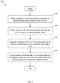
FIG. 2 illustrates an embodiment of a prioritizedservice restoration method 200, which may be used to restore E-LAN or similar services in a network, such in the E-LAN service basednetwork 100. Themethod 200 may be implemented by the network, a network server, the network management plane, one or more nodes in the network, or combinations thereof. Themethod 200 may begin atblock 230, where a plurality of services may be ordered based on a plurality of advertised priorities or ranks for the services. For instance, the network may detect a node or link failure that may be associated with an established E-LAN service. The network may then advertise the priorities or ranks of a plurality of services to a plurality of nodes. The service IDs and the service priorities or ranks may be advertised, e.g. to the nodes, implicitly or explicitly, as described above. The nodes may then order the services that have higher ranks before the lower ranked services. - At
block 240, a plurality of nodes may be ordered based on the ranks for the services that are originated by the nodes. As such, the nodes that originate services that have higher ranks may be ordered first before the nodes that originate lower ranked services. Atblock 250, a plurality of link or forwarding states for the services may be computed considering first the nodes that have higher order. Atblock 260, the calculated link or forwarding states for the higher ranked services may be downloaded first to the nodes before the forwarding states for the lower ranked services. Thus, the nodes may receive the forwarding states for the higher ranked services first and restore the higher ranked services before the lower ranked services. Themethod 200 may then end. - A node may receive and maintain the downloaded forwarding states and corresponding service IDs, which may be ordered in sequence from higher priority to lower priority link state based services. Thus, the node may restore the link state based services, e.g. instantiate work on the forwarding states, based on the ordered sequence from higher priority to lower priority link state based services. The node may also forward traffic on the forwarding states based on the same ordered sequence. The work instantiated on the forwarding states may comprise central processing unit (CPU) utilization, for example to process the forwarded traffic or other data between nodes. The work may also comprise task movement between resources.
-
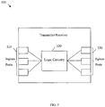
FIG. 3 illustrates an embodiment of a transmitter/receiver unit 300, which may be located at or coupled to any of the components described above, e.g. in the group-basedmulticast architecture 100. The transmitter/receiver unit 300 may be any device that transports data through the network. For instance, the transmitter/receiver unit 300 may correspond to or may be located in any of thenodes 110. The transmitted/receiver unit 300 may comprise a plurality of ingress ports orunits 310 for receiving frames, objects, or type-length-values (TLVs) from other nodes,logic circuitry 320 to determine which nodes to send the frames to, and a plurality of egress ports orunits 330 for transmitting frames to the other nodes. The transmitter/receiver unit 300 may also comprise a buffer (not shown) between theingress ports 310 and thelogic circuit 320 and/or between thelogic circuit 320 and theegress node 330. - The network components (e.g. the nodes 110) described above may be implemented on any general-purpose network component, such as a computer or network component with sufficient processing power, memory resources, and network throughput capability to handle the necessary workload placed upon it.
FIG. 4 illustrates a typical, general-purpose network component 400 suitable for implementing one or more embodiments of the components disclosed herein. Thenetwork component 400 includes a processor 402 (which may be referred to as a CPU that is in communication with memory devices includingsecondary storage 404, read only memory (ROM) 406, random access memory (RAM) 408, input/output (I/O)devices 410, andnetwork connectivity devices 412. Theprocessor 402 may be implemented as one or more CPU chips, or may be part of one or more application specific integrated circuits (ASICs). - The
secondary storage 404 is typically comprised of one or more disk drives or tape drives and is used for non-volatile storage of data and as an over-flow data storage device ifRAM 408 is not large enough to hold all working data.Secondary storage 404 may be used to store programs that are loaded intoRAM 408 when such programs are selected for execution. TheROM 406 is used to store instructions and perhaps data that are read during program execution.ROM 406 is a non-volatile memory device that typically has a small memory capacity relative to the larger memory capacity of secondary storage. TheRAM 408 is used to store volatile data and perhaps to store instructions. Access to bothROM 406 andRAM 408 is typically faster than tosecondary storage 404. - At least one embodiment is disclosed and variations, combinations, and/or modifications of the embodiment(s) and/or features of the embodiment(s) made by a person having ordinary skill in the art are within the scope of the disclosure. Alternative embodiments that result from combining, integrating, and/or omitting features of the embodiment(s) are also within the scope of the disclosure. Where numerical ranges or limitations are expressly stated, such express ranges or limitations should be understood to include iterative ranges or limitations of like magnitude falling within the expressly stated ranges or limitations (e.g. from about 1 to about 10 includes 2, 3, 4, etc.; greater than 0.10 includes 0.11, 0.12, 0.13, etc.). For example, whenever a numerical range with a lower limit, R1, and an upper limit, Ru, is disclosed, any number falling within the range is specifically disclosed. In particular, the following numbers within the range are specifically disclosed: R = R1 + k * (Ru - R1), wherein k is a variable ranging from 1 percent to 100 percent with a 1 percent increment, i.e., k is 1 percent, 2 percent, 3 percent, 4 percent, 5 percent, ..., 50 percent, 51 percent, 52 percent, ..., 95 percent, 96 percent, 97 percent, 98 percent, 99 percent, or 100 percent. Moreover, any numerical range defined by two R numbers as defined in the above is also specifically disclosed. Use of the term "optionally" with respect to any element of a claim means that the element is required, or alternatively, the element is not required, both alternatives being within the scope of the claim. Use of broader terms such as comprises, includes, and having should be understood to provide support for narrower terms such as consisting of, consisting essentially of, and comprised substantially of. Accordingly, the scope of protection is not limited by the description set out above but is defined by the claims that follow. Each and every claim is incorporated as further disclosure into the specification and the claims are embodiment(s) of the present disclosure. The discussion of a reference in the disclosure is not an admission that it is prior art, especially any reference that has a publication date after the priority date of this application.
- While several embodiments have been provided in the present disclosure, it should be understood that the disclosed systems and methods might be embodied in many other specific forms without departing from the scope of the present disclosure. The present examples are to be considered as illustrative and not restrictive, and the intention is not to be limited to the details given herein. For example, the various elements or components may be combined or integrated in another system or certain features may be omitted, or not implemented.
Claims (7)
- A network component comprising:
a receiver configured to receive a plurality of advertised ranks for a plurality of layer 2 services, wherein a layer 2 service is a service to carry data at a link layer in a same network; wherein the plurality of layer 2 services comprising at least two different types of layer 2 services; the network component being characterized in that it further comprises:a circuit (320) configured to order the plurality of layer 2 services based on the plurality of advertised ranks, to order a plurality of nodes (110) based on the ranks for the layer 2 services that are originated by the nodes (110), and to compute a plurality of forwarding tables for the layer 2 services considering first the nodes (110) that have higher order, each forwarding table associating traffic types with corresponding layer 2 services; anda transmitter configured to transmit the computed forwarding tables to the nodes (110) by transmitting first the computed forwarding tables for the higher ranked services, before transmitting the computed forwarding tables for the lower ranked services. - A network comprising the network component of claim 1, further comprising a node among the nodes, wherein the nodes (110) are configured to maintain a plurality of downloaded forwarding tables for a plurality of layer 2 services that are associated with at least the node (110) and a plurality of other nodes (110) in a network (100) comprising the node (110), and a plurality of advertised service identifiers, IDs, that correspond to the layer 2 services,
wherein the service IDs are ordered in sequence from higher priority to lower priority layer 2 services, and
wherein exchanging data with the other nodes (110) is performed at the node (110) according to the ordered sequence from higher priority to lower priority layer 2 services. - The network of claim 2, wherein the forwarding tables are downloaded after a network fault.
- The network of any claim of claims 2 -3, wherein the layer 2 services are Institute of Electrical and Electronics Engineers, IEEE, 802.1aq based services at the Open Systems Interconnection, OSI, network Layer Two, layer 2, or Virtual Private Local Area Network, LAN, based services, VPLS.
- A computer-implemented method performed by a network component comprising:receiving a plurality of advertised ranks for a plurality of layer 2 services, wherein a layer 2 service is a service to carry data at a link layer in a same network; wherein the plurality of layer 2 services comprising at least two different types of layer 2 services;the method being characterized in that it further comprises:ordering (230) the plurality of layer 2 services based on a plurality of advertised ranks for the layer 2 services;ordering (240) a plurality of nodes (110) based on the ranks for the layer 2 services that are originated by the nodes (110);computing (250) a plurality of forwarding tables for the layer 2 services considering first the nodes (110) that have higher order, each forwarding table associating traffic types with corresponding layer 2 services; anddownloading (260) the computed forwarding tables to the nodes (110) by downloading first the computed forwarding tables for the higher ranked services, before transmitting the computed forwarding tables for the lower ranked services.
- The method of claim 5, wherein the ranks for the layer 2 services are advertised after detecting a network fault, and wherein the layer 2 services comprise Ethernet Local Area Network, E-LAN, services.
- The method of any claim of claims 5-6, further comprising:ordering a plurality of layer 2 services per node (110); andcomputing a plurality of forwarding tables for the layer 2 services based on the ordered layer 2 services per node (110).
Applications Claiming Priority (3)
| Application Number | Priority Date | Filing Date | Title |
|---|---|---|---|
| US31444510P | 2010-03-16 | 2010-03-16 | |
| US13/013,394 US8873401B2 (en) | 2010-03-16 | 2011-01-25 | Service prioritization in link state controlled layer two networks |
| PCT/CN2011/071414 WO2011113323A1 (en) | 2010-03-16 | 2011-03-01 | Service prioritization in link state controlled layer two networks |
Publications (3)
| Publication Number | Publication Date |
|---|---|
| EP2548347A1 EP2548347A1 (en) | 2013-01-23 |
| EP2548347A4 EP2548347A4 (en) | 2013-07-31 |
| EP2548347B1 true EP2548347B1 (en) | 2018-08-15 |
Family
ID=44647217
Family Applications (1)
| Application Number | Title | Priority Date | Filing Date |
|---|---|---|---|
| EP11755640.7A Active EP2548347B1 (en) | 2010-03-16 | 2011-03-01 | Service prioritization in link state controlled layer two networks |
Country Status (4)
| Country | Link |
|---|---|
| US (1) | US8873401B2 (en) |
| EP (1) | EP2548347B1 (en) |
| CN (1) | CN102792649B (en) |
| WO (1) | WO2011113323A1 (en) |
Families Citing this family (156)
| Publication number | Priority date | Publication date | Assignee | Title |
|---|---|---|---|---|
| US8665886B2 (en) | 2009-03-26 | 2014-03-04 | Brocade Communications Systems, Inc. | Redundant host connection in a routed network |
| US8369335B2 (en) | 2010-03-24 | 2013-02-05 | Brocade Communications Systems, Inc. | Method and system for extending routing domain to non-routing end stations |
| US9001824B2 (en) | 2010-05-18 | 2015-04-07 | Brocade Communication Systems, Inc. | Fabric formation for virtual cluster switching |
| US9769016B2 (en) | 2010-06-07 | 2017-09-19 | Brocade Communications Systems, Inc. | Advanced link tracking for virtual cluster switching |
| US9270486B2 (en) | 2010-06-07 | 2016-02-23 | Brocade Communications Systems, Inc. | Name services for virtual cluster switching |
| US9461840B2 (en) | 2010-06-02 | 2016-10-04 | Brocade Communications Systems, Inc. | Port profile management for virtual cluster switching |
| US9231890B2 (en) | 2010-06-08 | 2016-01-05 | Brocade Communications Systems, Inc. | Traffic management for virtual cluster switching |
| US8989186B2 (en) | 2010-06-08 | 2015-03-24 | Brocade Communication Systems, Inc. | Virtual port grouping for virtual cluster switching |
| US9716672B2 (en) | 2010-05-28 | 2017-07-25 | Brocade Communications Systems, Inc. | Distributed configuration management for virtual cluster switching |
| US8867552B2 (en) | 2010-05-03 | 2014-10-21 | Brocade Communications Systems, Inc. | Virtual cluster switching |
| US8885488B2 (en) | 2010-06-02 | 2014-11-11 | Brocade Communication Systems, Inc. | Reachability detection in trill networks |
| US9608833B2 (en) | 2010-06-08 | 2017-03-28 | Brocade Communications Systems, Inc. | Supporting multiple multicast trees in trill networks |
| US9628293B2 (en) | 2010-06-08 | 2017-04-18 | Brocade Communications Systems, Inc. | Network layer multicasting in trill networks |
| US8446914B2 (en) | 2010-06-08 | 2013-05-21 | Brocade Communications Systems, Inc. | Method and system for link aggregation across multiple switches |
| US9246703B2 (en) | 2010-06-08 | 2016-01-26 | Brocade Communications Systems, Inc. | Remote port mirroring |
| US9806906B2 (en) | 2010-06-08 | 2017-10-31 | Brocade Communications Systems, Inc. | Flooding packets on a per-virtual-network basis |
| US9807031B2 (en) | 2010-07-16 | 2017-10-31 | Brocade Communications Systems, Inc. | System and method for network configuration |
| US9270572B2 (en) | 2011-05-02 | 2016-02-23 | Brocade Communications Systems Inc. | Layer-3 support in TRILL networks |
| US8898251B2 (en) * | 2011-05-03 | 2014-11-25 | Microsoft Corporation | Client calculation of links to network locations of files to upload |
| US9497073B2 (en) * | 2011-06-17 | 2016-11-15 | International Business Machines Corporation | Distributed link aggregation group (LAG) for a layer 2 fabric |
| US9407533B2 (en) | 2011-06-28 | 2016-08-02 | Brocade Communications Systems, Inc. | Multicast in a trill network |
| US9401861B2 (en) * | 2011-06-28 | 2016-07-26 | Brocade Communications Systems, Inc. | Scalable MAC address distribution in an Ethernet fabric switch |
| US8948056B2 (en) | 2011-06-28 | 2015-02-03 | Brocade Communication Systems, Inc. | Spanning-tree based loop detection for an ethernet fabric switch |
| US8879549B2 (en) | 2011-06-28 | 2014-11-04 | Brocade Communications Systems, Inc. | Clearing forwarding entries dynamically and ensuring consistency of tables across ethernet fabric switch |
| US9007958B2 (en) | 2011-06-29 | 2015-04-14 | Brocade Communication Systems, Inc. | External loop detection for an ethernet fabric switch |
| US8885641B2 (en) | 2011-06-30 | 2014-11-11 | Brocade Communication Systems, Inc. | Efficient trill forwarding |
| US9736085B2 (en) | 2011-08-29 | 2017-08-15 | Brocade Communications Systems, Inc. | End-to end lossless Ethernet in Ethernet fabric |
| US9699117B2 (en) | 2011-11-08 | 2017-07-04 | Brocade Communications Systems, Inc. | Integrated fibre channel support in an ethernet fabric switch |
| US9450870B2 (en) | 2011-11-10 | 2016-09-20 | Brocade Communications Systems, Inc. | System and method for flow management in software-defined networks |
| CN102387042B (en) * | 2011-11-22 | 2014-03-12 | 华为技术有限公司 | Automatic configuration method and system as well as network node |
| US8995272B2 (en) | 2012-01-26 | 2015-03-31 | Brocade Communication Systems, Inc. | Link aggregation in software-defined networks |
| US9742693B2 (en) | 2012-02-27 | 2017-08-22 | Brocade Communications Systems, Inc. | Dynamic service insertion in a fabric switch |
| US9154416B2 (en) | 2012-03-22 | 2015-10-06 | Brocade Communications Systems, Inc. | Overlay tunnel in a fabric switch |
| US9025432B2 (en) * | 2012-05-07 | 2015-05-05 | Cisco Technology, Inc. | Optimization for trill LAN hellos |
| US8867367B2 (en) * | 2012-05-10 | 2014-10-21 | Telefonaktiebolaget L M Ericsson (Publ) | 802.1aq support over IETF EVPN |
| US9374301B2 (en) | 2012-05-18 | 2016-06-21 | Brocade Communications Systems, Inc. | Network feedback in software-defined networks |
| US10277464B2 (en) | 2012-05-22 | 2019-04-30 | Arris Enterprises Llc | Client auto-configuration in a multi-switch link aggregation |
| WO2013177289A1 (en) | 2012-05-23 | 2013-11-28 | Brocade Communications Systems, Inc. | Layer-3 overlay gateways |
| US9602430B2 (en) | 2012-08-21 | 2017-03-21 | Brocade Communications Systems, Inc. | Global VLANs for fabric switches |
| US8902794B2 (en) * | 2012-09-27 | 2014-12-02 | Cisco Technology, Inc. | System and method for providing N-way link-state routing redundancy without peer links in a network environment |
| US9049233B2 (en) | 2012-10-05 | 2015-06-02 | Cisco Technology, Inc. | MPLS segment-routing |
| US9369371B2 (en) | 2012-10-05 | 2016-06-14 | Cisco Technologies, Inc. | Method and system for path monitoring using segment routing |
| US9401872B2 (en) | 2012-11-16 | 2016-07-26 | Brocade Communications Systems, Inc. | Virtual link aggregations across multiple fabric switches |
| US10404583B1 (en) | 2012-12-27 | 2019-09-03 | Sitting Man, Llc | Routing methods, systems, and computer program products using multiple outside-scope identifiers |
| US10411997B1 (en) | 2012-12-27 | 2019-09-10 | Sitting Man, Llc | Routing methods, systems, and computer program products for using a region scoped node identifier |
| US10587505B1 (en) | 2012-12-27 | 2020-03-10 | Sitting Man, Llc | Routing methods, systems, and computer program products |
| US10419334B1 (en) | 2012-12-27 | 2019-09-17 | Sitting Man, Llc | Internet protocol routing methods, systems, and computer program products |
| US10397101B1 (en) | 2012-12-27 | 2019-08-27 | Sitting Man, Llc | Routing methods, systems, and computer program products for mapping identifiers |
| US10212076B1 (en) | 2012-12-27 | 2019-02-19 | Sitting Man, Llc | Routing methods, systems, and computer program products for mapping a node-scope specific identifier |
| US10476787B1 (en) | 2012-12-27 | 2019-11-12 | Sitting Man, Llc | Routing methods, systems, and computer program products |
| US10404582B1 (en) | 2012-12-27 | 2019-09-03 | Sitting Man, Llc | Routing methods, systems, and computer program products using an outside-scope indentifier |
| US10374938B1 (en) | 2012-12-27 | 2019-08-06 | Sitting Man, Llc | Routing methods, systems, and computer program products |
| US10447575B1 (en) | 2012-12-27 | 2019-10-15 | Sitting Man, Llc | Routing methods, systems, and computer program products |
| US10419335B1 (en) | 2012-12-27 | 2019-09-17 | Sitting Man, Llc | Region scope-specific outside-scope indentifier-equipped routing methods, systems, and computer program products |
| US10411998B1 (en) | 2012-12-27 | 2019-09-10 | Sitting Man, Llc | Node scope-specific outside-scope identifier-equipped routing methods, systems, and computer program products |
| US10397100B1 (en) | 2012-12-27 | 2019-08-27 | Sitting Man, Llc | Routing methods, systems, and computer program products using a region scoped outside-scope identifier |
| US10904144B2 (en) | 2012-12-27 | 2021-01-26 | Sitting Man, Llc | Methods, systems, and computer program products for associating a name with a network path |
| US9413691B2 (en) | 2013-01-11 | 2016-08-09 | Brocade Communications Systems, Inc. | MAC address synchronization in a fabric switch |
| US9350680B2 (en) | 2013-01-11 | 2016-05-24 | Brocade Communications Systems, Inc. | Protection switching over a virtual link aggregation |
| US9548926B2 (en) | 2013-01-11 | 2017-01-17 | Brocade Communications Systems, Inc. | Multicast traffic load balancing over virtual link aggregation |
| US9565113B2 (en) | 2013-01-15 | 2017-02-07 | Brocade Communications Systems, Inc. | Adaptive link aggregation and virtual link aggregation |
| US9565099B2 (en) | 2013-03-01 | 2017-02-07 | Brocade Communications Systems, Inc. | Spanning tree in fabric switches |
| US9559954B2 (en) | 2013-03-11 | 2017-01-31 | Cisco Technology, Inc. | Indexed segment ID |
| US9565160B2 (en) | 2013-03-11 | 2017-02-07 | Cisco Technology, Inc. | Advertisement of adjacency segment identifiers |
| US9537769B2 (en) | 2013-03-15 | 2017-01-03 | Cisco Technology, Inc. | Opportunistic compression of routing segment identifier stacks |
| US9537718B2 (en) | 2013-03-15 | 2017-01-03 | Cisco Technology, Inc. | Segment routing over label distribution protocol |
| US9401818B2 (en) | 2013-03-15 | 2016-07-26 | Brocade Communications Systems, Inc. | Scalable gateways for a fabric switch |
| US9565028B2 (en) | 2013-06-10 | 2017-02-07 | Brocade Communications Systems, Inc. | Ingress switch multicast distribution in a fabric switch |
| US9699001B2 (en) | 2013-06-10 | 2017-07-04 | Brocade Communications Systems, Inc. | Scalable and segregated network virtualization |
| US9806949B2 (en) | 2013-09-06 | 2017-10-31 | Brocade Communications Systems, Inc. | Transparent interconnection of Ethernet fabric switches |
| US9912612B2 (en) | 2013-10-28 | 2018-03-06 | Brocade Communications Systems LLC | Extended ethernet fabric switches |
| US9548873B2 (en) | 2014-02-10 | 2017-01-17 | Brocade Communications Systems, Inc. | Virtual extensible LAN tunnel keepalives |
| US9762488B2 (en) | 2014-03-06 | 2017-09-12 | Cisco Technology, Inc. | Segment routing extension headers |
| US10581758B2 (en) | 2014-03-19 | 2020-03-03 | Avago Technologies International Sales Pte. Limited | Distributed hot standby links for vLAG |
| US10476698B2 (en) | 2014-03-20 | 2019-11-12 | Avago Technologies International Sales Pte. Limited | Redundent virtual link aggregation group |
| US10063473B2 (en) | 2014-04-30 | 2018-08-28 | Brocade Communications Systems LLC | Method and system for facilitating switch virtualization in a network of interconnected switches |
| US9800471B2 (en) | 2014-05-13 | 2017-10-24 | Brocade Communications Systems, Inc. | Network extension groups of global VLANs in a fabric switch |
| US9401858B2 (en) | 2014-06-30 | 2016-07-26 | Cisco Technology, Inc. | Loop avoidance during network convergence in switched networks |
| US9807001B2 (en) | 2014-07-17 | 2017-10-31 | Cisco Technology, Inc. | Segment routing using a remote forwarding adjacency identifier |
| US10616108B2 (en) | 2014-07-29 | 2020-04-07 | Avago Technologies International Sales Pte. Limited | Scalable MAC address virtualization |
| US9544219B2 (en) | 2014-07-31 | 2017-01-10 | Brocade Communications Systems, Inc. | Global VLAN services |
| US9807007B2 (en) | 2014-08-11 | 2017-10-31 | Brocade Communications Systems, Inc. | Progressive MAC address learning |
| US9524173B2 (en) | 2014-10-09 | 2016-12-20 | Brocade Communications Systems, Inc. | Fast reboot for a switch |
| US9699029B2 (en) | 2014-10-10 | 2017-07-04 | Brocade Communications Systems, Inc. | Distributed configuration management in a switch group |
| CN104394098B (en) * | 2014-11-20 | 2018-07-10 | 迈普通信技术股份有限公司 | A kind of message processing method and device |
| US9626255B2 (en) | 2014-12-31 | 2017-04-18 | Brocade Communications Systems, Inc. | Online restoration of a switch snapshot |
| US9628407B2 (en) | 2014-12-31 | 2017-04-18 | Brocade Communications Systems, Inc. | Multiple software versions in a switch group |
| US9942097B2 (en) | 2015-01-05 | 2018-04-10 | Brocade Communications Systems LLC | Power management in a network of interconnected switches |
| US10003552B2 (en) | 2015-01-05 | 2018-06-19 | Brocade Communications Systems, Llc. | Distributed bidirectional forwarding detection protocol (D-BFD) for cluster of interconnected switches |
| US10341221B2 (en) | 2015-02-26 | 2019-07-02 | Cisco Technology, Inc. | Traffic engineering for bit indexed explicit replication |
| US10038592B2 (en) | 2015-03-17 | 2018-07-31 | Brocade Communications Systems LLC | Identifier assignment to a new switch in a switch group |
| US9807005B2 (en) | 2015-03-17 | 2017-10-31 | Brocade Communications Systems, Inc. | Multi-fabric manager |
| US10579406B2 (en) | 2015-04-08 | 2020-03-03 | Avago Technologies International Sales Pte. Limited | Dynamic orchestration of overlay tunnels |
| US10439929B2 (en) | 2015-07-31 | 2019-10-08 | Avago Technologies International Sales Pte. Limited | Graceful recovery of a multicast-enabled switch |
| US10673742B2 (en) | 2015-09-10 | 2020-06-02 | Telefonaktiebolaget Lm Ericsson (Publ) | Multicast state reduction via tunneling in a routed system |
| US10171303B2 (en) | 2015-09-16 | 2019-01-01 | Avago Technologies International Sales Pte. Limited | IP-based interconnection of switches with a logical chassis |
| US10164907B2 (en) | 2015-11-25 | 2018-12-25 | Telefonaktiebolaget Lm Ericsson (Publ) | Method and system for completing loosely specified MDTs |
| US9912614B2 (en) | 2015-12-07 | 2018-03-06 | Brocade Communications Systems LLC | Interconnection of switches based on hierarchical overlay tunneling |
| US9954765B2 (en) | 2016-01-08 | 2018-04-24 | Telefonaktiebolaget Lm Ericsson (Publ) | Graph construction for computed spring multicast |
| US10523456B2 (en) | 2016-03-28 | 2019-12-31 | Telefonaktiebolaget Lm Ericsson (Publ) | Multipoint to multipoint trees for computed spring multicast |
| US9838377B1 (en) | 2016-05-11 | 2017-12-05 | Oracle International Corporation | Task segregation in a multi-tenant identity and data security management cloud service |
| US9838376B1 (en) | 2016-05-11 | 2017-12-05 | Oracle International Corporation | Microservices based multi-tenant identity and data security management cloud service |
| US10878079B2 (en) | 2016-05-11 | 2020-12-29 | Oracle International Corporation | Identity cloud service authorization model with dynamic roles and scopes |
| US10581820B2 (en) | 2016-05-11 | 2020-03-03 | Oracle International Corporation | Key generation and rollover |
| US10454940B2 (en) | 2016-05-11 | 2019-10-22 | Oracle International Corporation | Identity cloud service authorization model |
| US9781122B1 (en) | 2016-05-11 | 2017-10-03 | Oracle International Corporation | Multi-tenant identity and data security management cloud service |
| US10341410B2 (en) | 2016-05-11 | 2019-07-02 | Oracle International Corporation | Security tokens for a multi-tenant identity and data security management cloud service |
| US10425386B2 (en) | 2016-05-11 | 2019-09-24 | Oracle International Corporation | Policy enforcement point for a multi-tenant identity and data security management cloud service |
| US10263881B2 (en) | 2016-05-26 | 2019-04-16 | Cisco Technology, Inc. | Enforcing strict shortest path forwarding using strict segment identifiers |
| US10585682B2 (en) | 2016-08-05 | 2020-03-10 | Oracle International Corporation | Tenant self-service troubleshooting for a multi-tenant identity and data security management cloud service |
| US10263947B2 (en) | 2016-08-05 | 2019-04-16 | Oracle International Corporation | LDAP to SCIM proxy service |
| US10255061B2 (en) * | 2016-08-05 | 2019-04-09 | Oracle International Corporation | Zero down time upgrade for a multi-tenant identity and data security management cloud service |
| US10735394B2 (en) | 2016-08-05 | 2020-08-04 | Oracle International Corporation | Caching framework for a multi-tenant identity and data security management cloud service |
| US10721237B2 (en) | 2016-08-05 | 2020-07-21 | Oracle International Corporation | Hierarchical processing for a virtual directory system for LDAP to SCIM proxy service |
| US10530578B2 (en) | 2016-08-05 | 2020-01-07 | Oracle International Corporation | Key store service |
| US10516672B2 (en) | 2016-08-05 | 2019-12-24 | Oracle International Corporation | Service discovery for a multi-tenant identity and data security management cloud service |
| US10484382B2 (en) | 2016-08-31 | 2019-11-19 | Oracle International Corporation | Data management for a multi-tenant identity cloud service |
| US10846390B2 (en) | 2016-09-14 | 2020-11-24 | Oracle International Corporation | Single sign-on functionality for a multi-tenant identity and data security management cloud service |
| US10511589B2 (en) | 2016-09-14 | 2019-12-17 | Oracle International Corporation | Single logout functionality for a multi-tenant identity and data security management cloud service |
| US10594684B2 (en) | 2016-09-14 | 2020-03-17 | Oracle International Corporation | Generating derived credentials for a multi-tenant identity cloud service |
| US11032197B2 (en) | 2016-09-15 | 2021-06-08 | Cisco Technology, Inc. | Reroute detection in segment routing data plane |
| US10484243B2 (en) | 2016-09-16 | 2019-11-19 | Oracle International Corporation | Application management for a multi-tenant identity cloud service |
| US10791087B2 (en) | 2016-09-16 | 2020-09-29 | Oracle International Corporation | SCIM to LDAP mapping using subtype attributes |
| US10341354B2 (en) | 2016-09-16 | 2019-07-02 | Oracle International Corporation | Distributed high availability agent architecture |
| US10445395B2 (en) | 2016-09-16 | 2019-10-15 | Oracle International Corporation | Cookie based state propagation for a multi-tenant identity cloud service |
| EP3513542B1 (en) | 2016-09-16 | 2021-05-19 | Oracle International Corporation | Tenant and service management for a multi-tenant identity and data security management cloud service |
| US10567364B2 (en) | 2016-09-16 | 2020-02-18 | Oracle International Corporation | Preserving LDAP hierarchy in a SCIM directory using special marker groups |
| US10904074B2 (en) | 2016-09-17 | 2021-01-26 | Oracle International Corporation | Composite event handler for a multi-tenant identity cloud service |
| US10237090B2 (en) | 2016-10-28 | 2019-03-19 | Avago Technologies International Sales Pte. Limited | Rule-based network identifier mapping |
| US10261836B2 (en) | 2017-03-21 | 2019-04-16 | Oracle International Corporation | Dynamic dispatching of workloads spanning heterogeneous services |
| US10454915B2 (en) | 2017-05-18 | 2019-10-22 | Oracle International Corporation | User authentication using kerberos with identity cloud service |
| US10348858B2 (en) | 2017-09-15 | 2019-07-09 | Oracle International Corporation | Dynamic message queues for a microservice based cloud service |
| US10831789B2 (en) | 2017-09-27 | 2020-11-10 | Oracle International Corporation | Reference attribute query processing for a multi-tenant cloud service |
| US11271969B2 (en) | 2017-09-28 | 2022-03-08 | Oracle International Corporation | Rest-based declarative policy management |
| US10834137B2 (en) | 2017-09-28 | 2020-11-10 | Oracle International Corporation | Rest-based declarative policy management |
| US10705823B2 (en) | 2017-09-29 | 2020-07-07 | Oracle International Corporation | Application templates and upgrade framework for a multi-tenant identity cloud service |
| US10715564B2 (en) | 2018-01-29 | 2020-07-14 | Oracle International Corporation | Dynamic client registration for an identity cloud service |
| US10931656B2 (en) | 2018-03-27 | 2021-02-23 | Oracle International Corporation | Cross-region trust for a multi-tenant identity cloud service |
| US11165634B2 (en) | 2018-04-02 | 2021-11-02 | Oracle International Corporation | Data replication conflict detection and resolution for a multi-tenant identity cloud service |
| US10798165B2 (en) | 2018-04-02 | 2020-10-06 | Oracle International Corporation | Tenant data comparison for a multi-tenant identity cloud service |
| US11258775B2 (en) | 2018-04-04 | 2022-02-22 | Oracle International Corporation | Local write for a multi-tenant identity cloud service |
| US11012444B2 (en) | 2018-06-25 | 2021-05-18 | Oracle International Corporation | Declarative third party identity provider integration for a multi-tenant identity cloud service |
| US10764273B2 (en) | 2018-06-28 | 2020-09-01 | Oracle International Corporation | Session synchronization across multiple devices in an identity cloud service |
| US10904136B2 (en) | 2018-08-06 | 2021-01-26 | Telefonaktiebolaget Lm Ericsson (Publ) | Multicast distribution tree versioning for minimizing multicast group traffic disruption |
| US11693835B2 (en) | 2018-10-17 | 2023-07-04 | Oracle International Corporation | Dynamic database schema allocation on tenant onboarding for a multi-tenant identity cloud service |
| US11321187B2 (en) | 2018-10-19 | 2022-05-03 | Oracle International Corporation | Assured lazy rollback for a multi-tenant identity cloud service |
| US11651357B2 (en) | 2019-02-01 | 2023-05-16 | Oracle International Corporation | Multifactor authentication without a user footprint |
| US11061929B2 (en) | 2019-02-08 | 2021-07-13 | Oracle International Corporation | Replication of resource type and schema metadata for a multi-tenant identity cloud service |
| US11321343B2 (en) | 2019-02-19 | 2022-05-03 | Oracle International Corporation | Tenant replication bootstrap for a multi-tenant identity cloud service |
| US11669321B2 (en) | 2019-02-20 | 2023-06-06 | Oracle International Corporation | Automated database upgrade for a multi-tenant identity cloud service |
| US11423111B2 (en) | 2019-02-25 | 2022-08-23 | Oracle International Corporation | Client API for rest based endpoints for a multi-tenant identify cloud service |
| US11792226B2 (en) | 2019-02-25 | 2023-10-17 | Oracle International Corporation | Automatic api document generation from scim metadata |
| US11687378B2 (en) | 2019-09-13 | 2023-06-27 | Oracle International Corporation | Multi-tenant identity cloud service with on-premise authentication integration and bridge high availability |
| US11870770B2 (en) | 2019-09-13 | 2024-01-09 | Oracle International Corporation | Multi-tenant identity cloud service with on-premise authentication integration |
| US11140074B2 (en) | 2019-09-24 | 2021-10-05 | Cisco Technology, Inc. | Communicating packets across multi-domain networks using compact forwarding instructions |
| US11611548B2 (en) | 2019-11-22 | 2023-03-21 | Oracle International Corporation | Bulk multifactor authentication enrollment |
Citations (3)
| Publication number | Priority date | Publication date | Assignee | Title |
|---|---|---|---|---|
| WO1998024244A2 (en) * | 1996-11-26 | 1998-06-04 | Mci Communications Corporation | Method and apparatus for identifying restoral routes in a network |
| WO1998041041A1 (en) * | 1997-03-12 | 1998-09-17 | Alcatel Network Systems, Inc. | Telecommunications network distributed restoration method and system |
| EP1542400A2 (en) * | 2003-12-12 | 2005-06-15 | Kabushiki Kaisha Toshiba | Selecting a wireless LAN access point based on a communication profile |
Family Cites Families (35)
| Publication number | Priority date | Publication date | Assignee | Title |
|---|---|---|---|---|
| US6226273B1 (en) * | 1993-11-30 | 2001-05-01 | British Telecommunicatioins Public Limited Company | Communications network management |
| JP3259126B2 (en) * | 1995-09-26 | 2002-02-25 | 富士通株式会社 | Ring transmission system and squelch method for the system |
| EP1142376A1 (en) | 1999-01-14 | 2001-10-10 | Telefonaktiebolaget L M Ericsson (Publ) | Priority transmission for various types of speech in network traffic |
| CN1281008C (en) * | 2000-07-28 | 2006-10-18 | 索尼公司 | Digital broadcasting system |
| EP1180862A1 (en) * | 2000-08-18 | 2002-02-20 | Sony International (Europe) GmbH | Broadcast receiver that is turned on automatically in accordance with a schedule of a transmitted service |
| US20020069279A1 (en) * | 2000-12-29 | 2002-06-06 | Romero Francisco J. | Apparatus and method for routing a transaction based on a requested level of service |
| US7639617B2 (en) * | 2001-06-27 | 2009-12-29 | Cisco Technology, Inc. | Upstream physical interface for modular cable modem termination system |
| JP4339536B2 (en) * | 2001-11-02 | 2009-10-07 | ソニー株式会社 | Automatic address assignment apparatus, control method therefor, and program |
| US7333438B1 (en) * | 2002-06-21 | 2008-02-19 | Nortel Networks Limited | Priority and policy based recovery in connection-oriented communication networks |
| JP2004120534A (en) * | 2002-09-27 | 2004-04-15 | Matsushita Electric Ind Co Ltd | Router, repeater and forwarding method |
| NZ525951A (en) | 2003-05-15 | 2005-07-29 | Zanick Entpr Ltd | A Method and System for Prioritising Incoming Communications which is placed in an ordered queue on the basis of an associated priority indicator |
| EP1489784A1 (en) * | 2003-06-16 | 2004-12-22 | Alcatel | Restoration in an automatically switched optical transport network |
| US7945675B2 (en) * | 2003-11-03 | 2011-05-17 | Apacheta Corporation | System and method for delegation of data processing tasks based on device physical attributes and spatial behavior |
| KR100664278B1 (en) * | 2004-01-09 | 2007-01-04 | 엘지전자 주식회사 | Radio communication system providing mbms |
| US7609637B2 (en) * | 2004-03-03 | 2009-10-27 | Alcatel-Lucent Usa Inc. | Network quality of service management |
| US7978708B2 (en) * | 2004-12-29 | 2011-07-12 | Cisco Technology, Inc. | Automatic route tagging of BGP next-hop routes in IGP |
| US20060198316A1 (en) * | 2005-03-02 | 2006-09-07 | Cable Television Laboratories, Inc. | System for remote configuration of QoS parameters |
| US20060212348A1 (en) * | 2005-03-15 | 2006-09-21 | Lambert Matthew C | Method for scheduling of broadcast events |
| CN1889701B (en) | 2005-08-19 | 2010-10-27 | 华为技术有限公司 | Method for playing prompting tone in intelligent call |
| ES2383613T3 (en) * | 2005-10-05 | 2012-06-22 | Nortel Networks Limited | Formation of state bridges of supplier links |
| CN100396009C (en) * | 2006-02-23 | 2008-06-18 | 华为技术有限公司 | Method and system for control bandwidth |
| JP2007251818A (en) * | 2006-03-17 | 2007-09-27 | Fujitsu Ltd | Program, method and device for transmission control |
| US7869348B2 (en) * | 2006-04-10 | 2011-01-11 | Polytechnic Institute Of New York University | Determining rerouting information for single-link failure recovery in an Internet protocol network |
| US20080025250A1 (en) * | 2006-07-28 | 2008-01-31 | Motorola, Inc. | Method and system for setting paging indication sequences in paging messages |
| US20080107027A1 (en) * | 2006-11-02 | 2008-05-08 | Nortel Networks Limited | Engineered paths in a link state protocol controlled Ethernet network |
| US8144699B2 (en) * | 2006-11-21 | 2012-03-27 | Cisco Technology, Inc. | Auto-provisioning of network services over an ethernet access link |
| US8223668B2 (en) * | 2006-12-14 | 2012-07-17 | Rockstar Bidco Lp | Method and apparatus for exchanging routing information and the establishment of connectivity across multiple network areas |
| US7693164B1 (en) * | 2007-02-05 | 2010-04-06 | World Wide Packets, Inc. | Configuring a packet tunnel network |
| CN100574475C (en) | 2007-06-19 | 2009-12-23 | 中兴通讯股份有限公司 | A kind of implementation method of intelligent network user immediate state service |
| US7898965B2 (en) * | 2007-10-12 | 2011-03-01 | Nortel Networks Limited | IP network and performance monitoring using ethernet OAM |
| US7894450B2 (en) * | 2007-12-31 | 2011-02-22 | Nortel Network, Ltd. | Implementation of VPNs over a link state protocol controlled ethernet network |
| US8068808B2 (en) * | 2008-04-16 | 2011-11-29 | Rivada Networks Llc | Method and system for providing a deployable emergency call service for wireless handsets |
| US8045570B2 (en) * | 2008-09-30 | 2011-10-25 | Nortel Networks Limited | Extended private LAN |
| US9384097B2 (en) * | 2009-09-09 | 2016-07-05 | Verisign, Inc. | Method and system for recovery of a failed registry |
| US20110170403A1 (en) * | 2010-01-08 | 2011-07-14 | Futurewei Technologies, Inc. | Service Movement in Link State Controlled Layer Two Networks |
-
2011
- 2011-01-25 US US13/013,394 patent/US8873401B2/en active Active
- 2011-03-01 CN CN201180013682.4A patent/CN102792649B/en active Active
- 2011-03-01 EP EP11755640.7A patent/EP2548347B1/en active Active
- 2011-03-01 WO PCT/CN2011/071414 patent/WO2011113323A1/en active Application Filing
Patent Citations (3)
| Publication number | Priority date | Publication date | Assignee | Title |
|---|---|---|---|---|
| WO1998024244A2 (en) * | 1996-11-26 | 1998-06-04 | Mci Communications Corporation | Method and apparatus for identifying restoral routes in a network |
| WO1998041041A1 (en) * | 1997-03-12 | 1998-09-17 | Alcatel Network Systems, Inc. | Telecommunications network distributed restoration method and system |
| EP1542400A2 (en) * | 2003-12-12 | 2005-06-15 | Kabushiki Kaisha Toshiba | Selecting a wireless LAN access point based on a communication profile |
Also Published As
| Publication number | Publication date |
|---|---|
| US20110228780A1 (en) | 2011-09-22 |
| CN102792649A (en) | 2012-11-21 |
| WO2011113323A1 (en) | 2011-09-22 |
| US8873401B2 (en) | 2014-10-28 |
| EP2548347A1 (en) | 2013-01-23 |
| EP2548347A4 (en) | 2013-07-31 |
| CN102792649B (en) | 2015-09-30 |
Similar Documents
| Publication | Publication Date | Title |
|---|---|---|
| EP2548347B1 (en) | Service prioritization in link state controlled layer two networks | |
| EP2783480B1 (en) | Method for multicast flow routing selection | |
| EP2817926B1 (en) | Delegate forwarding and address resolution in fragmented network | |
| US9680751B2 (en) | Methods and devices for providing service insertion in a TRILL network | |
| US9426068B2 (en) | Balancing of forwarding and address resolution in overlay networks | |
| US10050809B2 (en) | Adaptive load balancing for single active redundancy using EVPN designated forwarder election | |
| US8908527B2 (en) | Using context labels to scale MAC tables on computer network edge devices | |
| EP2750342A2 (en) | Engineered paths in a link state protocol controlled ethernet network | |
| US8929249B2 (en) | System and method for virtual private local area network service to use the flow aware pseudowire | |
| EP2989755B1 (en) | Efficient multicast delivery to dually connected (vpc) hosts in overlay networks | |
| US8767730B2 (en) | Virtual local area network identifier substitution as time to live method | |
| US20110170403A1 (en) | Service Movement in Link State Controlled Layer Two Networks | |
| CN109196819B (en) | Bidirectional multicast over virtual port channels | |
| CN112822097A (en) | Message forwarding method, first network device and first device group | |
| CN109561023A (en) | The methods, devices and systems of transport multicast message | |
| US20090245263A1 (en) | Apparatus and method for transmitting packets in a packet switched network | |
| US9203744B2 (en) | Convergence of multi-destination traffic in a network environment | |
| US10205661B1 (en) | Control messages for scalable satellite device clustering control in a campus network | |
| LSPs | Networking Working Group L. Ginsberg Internet-Draft S. Previdi Intended status: Standards Track Y. Yang Expires: December 18, 2013 Cisco Systems June 16, 2013 |
Legal Events
| Date | Code | Title | Description |
|---|---|---|---|
| PUAI | Public reference made under article 153(3) epc to a published international application that has entered the european phase |
Free format text: ORIGINAL CODE: 0009012 |
|
| 17P | Request for examination filed |
Effective date: 20120914 |
|
| AK | Designated contracting states |
Kind code of ref document: A1 Designated state(s): AL AT BE BG CH CY CZ DE DK EE ES FI FR GB GR HR HU IE IS IT LI LT LU LV MC MK MT NL NO PL PT RO RS SE SI SK SM TR |
|
| DAX | Request for extension of the european patent (deleted) | ||
| A4 | Supplementary search report drawn up and despatched |
Effective date: 20130628 |
|
| RIC1 | Information provided on ipc code assigned before grant |
Ipc: H04L 12/46 20060101AFI20130624BHEP |
|
| 17Q | First examination report despatched |
Effective date: 20140127 |
|
| STAA | Information on the status of an ep patent application or granted ep patent |
Free format text: STATUS: EXAMINATION IS IN PROGRESS |
|
| REG | Reference to a national code |
Ref country code: DE Ref legal event code: R079 Ref document number: 602011051081 Country of ref document: DE Free format text: PREVIOUS MAIN CLASS: H04L0012560000 Ipc: H04L0012751000 |
|
| GRAP | Despatch of communication of intention to grant a patent |
Free format text: ORIGINAL CODE: EPIDOSNIGR1 |
|
| STAA | Information on the status of an ep patent application or granted ep patent |
Free format text: STATUS: GRANT OF PATENT IS INTENDED |
|
| RIC1 | Information provided on ipc code assigned before grant |
Ipc: H04L 12/703 20130101ALI20180208BHEP Ipc: H04L 12/46 20060101ALI20180208BHEP Ipc: H04L 12/751 20130101AFI20180208BHEP |
|
| INTG | Intention to grant announced |
Effective date: 20180227 |
|
| GRAS | Grant fee paid |
Free format text: ORIGINAL CODE: EPIDOSNIGR3 |
|
| GRAA | (expected) grant |
Free format text: ORIGINAL CODE: 0009210 |
|
| STAA | Information on the status of an ep patent application or granted ep patent |
Free format text: STATUS: THE PATENT HAS BEEN GRANTED |
|
| AK | Designated contracting states |
Kind code of ref document: B1 Designated state(s): AL AT BE BG CH CY CZ DE DK EE ES FI FR GB GR HR HU IE IS IT LI LT LU LV MC MK MT NL NO PL PT RO RS SE SI SK SM TR |
|
| REG | Reference to a national code |
Ref country code: CH Ref legal event code: EP Ref country code: GB Ref legal event code: FG4D Ref country code: AT Ref legal event code: REF Ref document number: 1031061 Country of ref document: AT Kind code of ref document: T Effective date: 20180815 |
|
| REG | Reference to a national code |
Ref country code: IE Ref legal event code: FG4D |
|
| REG | Reference to a national code |
Ref country code: DE Ref legal event code: R096 Ref document number: 602011051081 Country of ref document: DE |
|
| REG | Reference to a national code |
Ref country code: NL Ref legal event code: MP Effective date: 20180815 |
|
| REG | Reference to a national code |
Ref country code: LT Ref legal event code: MG4D |
|
| REG | Reference to a national code |
Ref country code: AT Ref legal event code: MK05 Ref document number: 1031061 Country of ref document: AT Kind code of ref document: T Effective date: 20180815 |
|
| PG25 | Lapsed in a contracting state [announced via postgrant information from national office to epo] |
Ref country code: FI Free format text: LAPSE BECAUSE OF FAILURE TO SUBMIT A TRANSLATION OF THE DESCRIPTION OR TO PAY THE FEE WITHIN THE PRESCRIBED TIME-LIMIT Effective date: 20180815 Ref country code: IS Free format text: LAPSE BECAUSE OF FAILURE TO SUBMIT A TRANSLATION OF THE DESCRIPTION OR TO PAY THE FEE WITHIN THE PRESCRIBED TIME-LIMIT Effective date: 20181215 Ref country code: AT Free format text: LAPSE BECAUSE OF FAILURE TO SUBMIT A TRANSLATION OF THE DESCRIPTION OR TO PAY THE FEE WITHIN THE PRESCRIBED TIME-LIMIT Effective date: 20180815 Ref country code: NO Free format text: LAPSE BECAUSE OF FAILURE TO SUBMIT A TRANSLATION OF THE DESCRIPTION OR TO PAY THE FEE WITHIN THE PRESCRIBED TIME-LIMIT Effective date: 20181115 Ref country code: RS Free format text: LAPSE BECAUSE OF FAILURE TO SUBMIT A TRANSLATION OF THE DESCRIPTION OR TO PAY THE FEE WITHIN THE PRESCRIBED TIME-LIMIT Effective date: 20180815 Ref country code: GR Free format text: LAPSE BECAUSE OF FAILURE TO SUBMIT A TRANSLATION OF THE DESCRIPTION OR TO PAY THE FEE WITHIN THE PRESCRIBED TIME-LIMIT Effective date: 20181116 Ref country code: BG Free format text: LAPSE BECAUSE OF FAILURE TO SUBMIT A TRANSLATION OF THE DESCRIPTION OR TO PAY THE FEE WITHIN THE PRESCRIBED TIME-LIMIT Effective date: 20181115 Ref country code: SE Free format text: LAPSE BECAUSE OF FAILURE TO SUBMIT A TRANSLATION OF THE DESCRIPTION OR TO PAY THE FEE WITHIN THE PRESCRIBED TIME-LIMIT Effective date: 20180815 Ref country code: NL Free format text: LAPSE BECAUSE OF FAILURE TO SUBMIT A TRANSLATION OF THE DESCRIPTION OR TO PAY THE FEE WITHIN THE PRESCRIBED TIME-LIMIT Effective date: 20180815 Ref country code: LT Free format text: LAPSE BECAUSE OF FAILURE TO SUBMIT A TRANSLATION OF THE DESCRIPTION OR TO PAY THE FEE WITHIN THE PRESCRIBED TIME-LIMIT Effective date: 20180815 |
|
| PG25 | Lapsed in a contracting state [announced via postgrant information from national office to epo] |
Ref country code: HR Free format text: LAPSE BECAUSE OF FAILURE TO SUBMIT A TRANSLATION OF THE DESCRIPTION OR TO PAY THE FEE WITHIN THE PRESCRIBED TIME-LIMIT Effective date: 20180815 Ref country code: LV Free format text: LAPSE BECAUSE OF FAILURE TO SUBMIT A TRANSLATION OF THE DESCRIPTION OR TO PAY THE FEE WITHIN THE PRESCRIBED TIME-LIMIT Effective date: 20180815 Ref country code: AL Free format text: LAPSE BECAUSE OF FAILURE TO SUBMIT A TRANSLATION OF THE DESCRIPTION OR TO PAY THE FEE WITHIN THE PRESCRIBED TIME-LIMIT Effective date: 20180815 |
|
| PG25 | Lapsed in a contracting state [announced via postgrant information from national office to epo] |
Ref country code: CZ Free format text: LAPSE BECAUSE OF FAILURE TO SUBMIT A TRANSLATION OF THE DESCRIPTION OR TO PAY THE FEE WITHIN THE PRESCRIBED TIME-LIMIT Effective date: 20180815 Ref country code: RO Free format text: LAPSE BECAUSE OF FAILURE TO SUBMIT A TRANSLATION OF THE DESCRIPTION OR TO PAY THE FEE WITHIN THE PRESCRIBED TIME-LIMIT Effective date: 20180815 Ref country code: ES Free format text: LAPSE BECAUSE OF FAILURE TO SUBMIT A TRANSLATION OF THE DESCRIPTION OR TO PAY THE FEE WITHIN THE PRESCRIBED TIME-LIMIT Effective date: 20180815 Ref country code: PL Free format text: LAPSE BECAUSE OF FAILURE TO SUBMIT A TRANSLATION OF THE DESCRIPTION OR TO PAY THE FEE WITHIN THE PRESCRIBED TIME-LIMIT Effective date: 20180815 Ref country code: EE Free format text: LAPSE BECAUSE OF FAILURE TO SUBMIT A TRANSLATION OF THE DESCRIPTION OR TO PAY THE FEE WITHIN THE PRESCRIBED TIME-LIMIT Effective date: 20180815 Ref country code: IT Free format text: LAPSE BECAUSE OF FAILURE TO SUBMIT A TRANSLATION OF THE DESCRIPTION OR TO PAY THE FEE WITHIN THE PRESCRIBED TIME-LIMIT Effective date: 20180815 |
|
| REG | Reference to a national code |
Ref country code: DE Ref legal event code: R097 Ref document number: 602011051081 Country of ref document: DE |
|
| PG25 | Lapsed in a contracting state [announced via postgrant information from national office to epo] |
Ref country code: DK Free format text: LAPSE BECAUSE OF FAILURE TO SUBMIT A TRANSLATION OF THE DESCRIPTION OR TO PAY THE FEE WITHIN THE PRESCRIBED TIME-LIMIT Effective date: 20180815 Ref country code: SM Free format text: LAPSE BECAUSE OF FAILURE TO SUBMIT A TRANSLATION OF THE DESCRIPTION OR TO PAY THE FEE WITHIN THE PRESCRIBED TIME-LIMIT Effective date: 20180815 Ref country code: SK Free format text: LAPSE BECAUSE OF FAILURE TO SUBMIT A TRANSLATION OF THE DESCRIPTION OR TO PAY THE FEE WITHIN THE PRESCRIBED TIME-LIMIT Effective date: 20180815 |
|
| PLBE | No opposition filed within time limit |
Free format text: ORIGINAL CODE: 0009261 |
|
| STAA | Information on the status of an ep patent application or granted ep patent |
Free format text: STATUS: NO OPPOSITION FILED WITHIN TIME LIMIT |
|
| 26N | No opposition filed |
Effective date: 20190516 |
|
| PG25 | Lapsed in a contracting state [announced via postgrant information from national office to epo] |
Ref country code: SI Free format text: LAPSE BECAUSE OF FAILURE TO SUBMIT A TRANSLATION OF THE DESCRIPTION OR TO PAY THE FEE WITHIN THE PRESCRIBED TIME-LIMIT Effective date: 20180815 |
|
| PG25 | Lapsed in a contracting state [announced via postgrant information from national office to epo] |
Ref country code: MC Free format text: LAPSE BECAUSE OF FAILURE TO SUBMIT A TRANSLATION OF THE DESCRIPTION OR TO PAY THE FEE WITHIN THE PRESCRIBED TIME-LIMIT Effective date: 20180815 |
|
| REG | Reference to a national code |
Ref country code: CH Ref legal event code: PL |
|
| PG25 | Lapsed in a contracting state [announced via postgrant information from national office to epo] |
Ref country code: LU Free format text: LAPSE BECAUSE OF NON-PAYMENT OF DUE FEES Effective date: 20190301 |
|
| REG | Reference to a national code |
Ref country code: BE Ref legal event code: MM Effective date: 20190331 |
|
| PG25 | Lapsed in a contracting state [announced via postgrant information from national office to epo] |
Ref country code: LI Free format text: LAPSE BECAUSE OF NON-PAYMENT OF DUE FEES Effective date: 20190331 Ref country code: IE Free format text: LAPSE BECAUSE OF NON-PAYMENT OF DUE FEES Effective date: 20190301 Ref country code: CH Free format text: LAPSE BECAUSE OF NON-PAYMENT OF DUE FEES Effective date: 20190331 |
|
| PG25 | Lapsed in a contracting state [announced via postgrant information from national office to epo] |
Ref country code: BE Free format text: LAPSE BECAUSE OF NON-PAYMENT OF DUE FEES Effective date: 20190331 |
|
| PG25 | Lapsed in a contracting state [announced via postgrant information from national office to epo] |
Ref country code: TR Free format text: LAPSE BECAUSE OF FAILURE TO SUBMIT A TRANSLATION OF THE DESCRIPTION OR TO PAY THE FEE WITHIN THE PRESCRIBED TIME-LIMIT Effective date: 20180815 |
|
| PG25 | Lapsed in a contracting state [announced via postgrant information from national office to epo] |
Ref country code: PT Free format text: LAPSE BECAUSE OF FAILURE TO SUBMIT A TRANSLATION OF THE DESCRIPTION OR TO PAY THE FEE WITHIN THE PRESCRIBED TIME-LIMIT Effective date: 20181215 Ref country code: MT Free format text: LAPSE BECAUSE OF NON-PAYMENT OF DUE FEES Effective date: 20190301 |
|
| PG25 | Lapsed in a contracting state [announced via postgrant information from national office to epo] |
Ref country code: CY Free format text: LAPSE BECAUSE OF FAILURE TO SUBMIT A TRANSLATION OF THE DESCRIPTION OR TO PAY THE FEE WITHIN THE PRESCRIBED TIME-LIMIT Effective date: 20180815 |
|
| PG25 | Lapsed in a contracting state [announced via postgrant information from national office to epo] |
Ref country code: HU Free format text: LAPSE BECAUSE OF FAILURE TO SUBMIT A TRANSLATION OF THE DESCRIPTION OR TO PAY THE FEE WITHIN THE PRESCRIBED TIME-LIMIT; INVALID AB INITIO Effective date: 20110301 |
|
| REG | Reference to a national code |
Ref country code: DE Ref legal event code: R079 Ref document number: 602011051081 Country of ref document: DE Free format text: PREVIOUS MAIN CLASS: H04L0012751000 Ipc: H04L0045020000 |
|
| PG25 | Lapsed in a contracting state [announced via postgrant information from national office to epo] |
Ref country code: MK Free format text: LAPSE BECAUSE OF FAILURE TO SUBMIT A TRANSLATION OF THE DESCRIPTION OR TO PAY THE FEE WITHIN THE PRESCRIBED TIME-LIMIT Effective date: 20180815 |
|
| PGFP | Annual fee paid to national office [announced via postgrant information from national office to epo] |
Ref country code: FR Payment date: 20230208 Year of fee payment: 13 |
|
| PGFP | Annual fee paid to national office [announced via postgrant information from national office to epo] |
Ref country code: GB Payment date: 20230202 Year of fee payment: 13 Ref country code: DE Payment date: 20230131 Year of fee payment: 13 |