EP2542878B1 - Flexible sample container - Google Patents
Flexible sample container Download PDFInfo
- Publication number
- EP2542878B1 EP2542878B1 EP11750218.7A EP11750218A EP2542878B1 EP 2542878 B1 EP2542878 B1 EP 2542878B1 EP 11750218 A EP11750218 A EP 11750218A EP 2542878 B1 EP2542878 B1 EP 2542878B1
- Authority
- EP
- European Patent Office
- Prior art keywords
- tube
- less
- state
- fluid
- flexible tube
- Prior art date
- Legal status (The legal status is an assumption and is not a legal conclusion. Google has not performed a legal analysis and makes no representation as to the accuracy of the status listed.)
- Active
Links
- 239000012530 fluid Substances 0.000 claims description 62
- 230000003287 optical effect Effects 0.000 claims description 46
- 239000002245 particle Substances 0.000 claims description 25
- 238000000034 method Methods 0.000 claims description 19
- 230000004913 activation Effects 0.000 claims description 3
- 238000005259 measurement Methods 0.000 description 26
- XLYOFNOQVPJJNP-UHFFFAOYSA-N water Substances O XLYOFNOQVPJJNP-UHFFFAOYSA-N 0.000 description 14
- 210000004027 cell Anatomy 0.000 description 8
- 239000007788 liquid Substances 0.000 description 7
- 239000000463 material Substances 0.000 description 5
- 210000004369 blood Anatomy 0.000 description 4
- 239000008280 blood Substances 0.000 description 4
- 239000012780 transparent material Substances 0.000 description 4
- 241000894006 Bacteria Species 0.000 description 3
- 239000011521 glass Substances 0.000 description 3
- 229920003023 plastic Polymers 0.000 description 3
- 210000002700 urine Anatomy 0.000 description 3
- 230000000694 effects Effects 0.000 description 2
- 238000003384 imaging method Methods 0.000 description 2
- 210000000265 leukocyte Anatomy 0.000 description 2
- 230000010287 polarization Effects 0.000 description 2
- 229920001296 polysiloxane Polymers 0.000 description 2
- 239000013049 sediment Substances 0.000 description 2
- 239000000126 substance Substances 0.000 description 2
- 239000002699 waste material Substances 0.000 description 2
- 208000028399 Critical Illness Diseases 0.000 description 1
- FAPWRFPIFSIZLT-UHFFFAOYSA-M Sodium chloride Chemical compound [Na+].[Cl-] FAPWRFPIFSIZLT-UHFFFAOYSA-M 0.000 description 1
- 230000003213 activating effect Effects 0.000 description 1
- 238000005452 bending Methods 0.000 description 1
- 230000005540 biological transmission Effects 0.000 description 1
- 230000000903 blocking effect Effects 0.000 description 1
- 238000005119 centrifugation Methods 0.000 description 1
- 238000011109 contamination Methods 0.000 description 1
- 201000010099 disease Diseases 0.000 description 1
- 208000037265 diseases, disorders, signs and symptoms Diseases 0.000 description 1
- 230000002439 hemostatic effect Effects 0.000 description 1
- 238000001802 infusion Methods 0.000 description 1
- 238000001990 intravenous administration Methods 0.000 description 1
- 239000002184 metal Substances 0.000 description 1
- 239000008267 milk Substances 0.000 description 1
- 210000004080 milk Anatomy 0.000 description 1
- 235000013336 milk Nutrition 0.000 description 1
- 238000012544 monitoring process Methods 0.000 description 1
- 230000000704 physical effect Effects 0.000 description 1
- 238000005086 pumping Methods 0.000 description 1
- 238000004062 sedimentation Methods 0.000 description 1
- 239000011780 sodium chloride Substances 0.000 description 1
- 239000000243 solution Substances 0.000 description 1
- 238000011144 upstream manufacturing Methods 0.000 description 1
- -1 urine Substances 0.000 description 1
Images

Classifications
-
- G—PHYSICS
- G01—MEASURING; TESTING
- G01N—INVESTIGATING OR ANALYSING MATERIALS BY DETERMINING THEIR CHEMICAL OR PHYSICAL PROPERTIES
- G01N21/00—Investigating or analysing materials by the use of optical means, i.e. using sub-millimetre waves, infrared, visible or ultraviolet light
- G01N21/01—Arrangements or apparatus for facilitating the optical investigation
- G01N21/03—Cuvette constructions
- G01N21/05—Flow-through cuvettes
-
- B—PERFORMING OPERATIONS; TRANSPORTING
- B01—PHYSICAL OR CHEMICAL PROCESSES OR APPARATUS IN GENERAL
- B01L—CHEMICAL OR PHYSICAL LABORATORY APPARATUS FOR GENERAL USE
- B01L3/00—Containers or dishes for laboratory use, e.g. laboratory glassware; Droppers
-
- B—PERFORMING OPERATIONS; TRANSPORTING
- B01—PHYSICAL OR CHEMICAL PROCESSES OR APPARATUS IN GENERAL
- B01L—CHEMICAL OR PHYSICAL LABORATORY APPARATUS FOR GENERAL USE
- B01L3/00—Containers or dishes for laboratory use, e.g. laboratory glassware; Droppers
- B01L3/50—Containers for the purpose of retaining a material to be analysed, e.g. test tubes
- B01L3/505—Containers for the purpose of retaining a material to be analysed, e.g. test tubes flexible containers not provided for above
-
- G—PHYSICS
- G01—MEASURING; TESTING
- G01N—INVESTIGATING OR ANALYSING MATERIALS BY DETERMINING THEIR CHEMICAL OR PHYSICAL PROPERTIES
- G01N21/00—Investigating or analysing materials by the use of optical means, i.e. using sub-millimetre waves, infrared, visible or ultraviolet light
- G01N21/84—Systems specially adapted for particular applications
- G01N21/85—Investigating moving fluids or granular solids
-
- B—PERFORMING OPERATIONS; TRANSPORTING
- B01—PHYSICAL OR CHEMICAL PROCESSES OR APPARATUS IN GENERAL
- B01L—CHEMICAL OR PHYSICAL LABORATORY APPARATUS FOR GENERAL USE
- B01L2300/00—Additional constructional details
- B01L2300/08—Geometry, shape and general structure
- B01L2300/0832—Geometry, shape and general structure cylindrical, tube shaped
-
- B—PERFORMING OPERATIONS; TRANSPORTING
- B01—PHYSICAL OR CHEMICAL PROCESSES OR APPARATUS IN GENERAL
- B01L—CHEMICAL OR PHYSICAL LABORATORY APPARATUS FOR GENERAL USE
- B01L2300/00—Additional constructional details
- B01L2300/08—Geometry, shape and general structure
- B01L2300/0861—Configuration of multiple channels and/or chambers in a single devices
- B01L2300/0877—Flow chambers
-
- B—PERFORMING OPERATIONS; TRANSPORTING
- B01—PHYSICAL OR CHEMICAL PROCESSES OR APPARATUS IN GENERAL
- B01L—CHEMICAL OR PHYSICAL LABORATORY APPARATUS FOR GENERAL USE
- B01L2400/00—Moving or stopping fluids
- B01L2400/04—Moving fluids with specific forces or mechanical means
- B01L2400/0475—Moving fluids with specific forces or mechanical means specific mechanical means and fluid pressure
- B01L2400/0487—Moving fluids with specific forces or mechanical means specific mechanical means and fluid pressure fluid pressure, pneumatics
-
- B—PERFORMING OPERATIONS; TRANSPORTING
- B01—PHYSICAL OR CHEMICAL PROCESSES OR APPARATUS IN GENERAL
- B01L—CHEMICAL OR PHYSICAL LABORATORY APPARATUS FOR GENERAL USE
- B01L2400/00—Moving or stopping fluids
- B01L2400/06—Valves, specific forms thereof
- B01L2400/0633—Valves, specific forms thereof with moving parts
- B01L2400/0655—Valves, specific forms thereof with moving parts pinch valves
-
- G—PHYSICS
- G01—MEASURING; TESTING
- G01N—INVESTIGATING OR ANALYSING MATERIALS BY DETERMINING THEIR CHEMICAL OR PHYSICAL PROPERTIES
- G01N21/00—Investigating or analysing materials by the use of optical means, i.e. using sub-millimetre waves, infrared, visible or ultraviolet light
- G01N21/01—Arrangements or apparatus for facilitating the optical investigation
- G01N21/03—Cuvette constructions
- G01N2021/0346—Capillary cells; Microcells
-
- G—PHYSICS
- G01—MEASURING; TESTING
- G01N—INVESTIGATING OR ANALYSING MATERIALS BY DETERMINING THEIR CHEMICAL OR PHYSICAL PROPERTIES
- G01N21/00—Investigating or analysing materials by the use of optical means, i.e. using sub-millimetre waves, infrared, visible or ultraviolet light
- G01N21/01—Arrangements or apparatus for facilitating the optical investigation
- G01N21/03—Cuvette constructions
- G01N2021/0364—Cuvette constructions flexible, compressible
-
- G—PHYSICS
- G01—MEASURING; TESTING
- G01N—INVESTIGATING OR ANALYSING MATERIALS BY DETERMINING THEIR CHEMICAL OR PHYSICAL PROPERTIES
- G01N21/00—Investigating or analysing materials by the use of optical means, i.e. using sub-millimetre waves, infrared, visible or ultraviolet light
- G01N21/84—Systems specially adapted for particular applications
- G01N21/85—Investigating moving fluids or granular solids
- G01N2021/8557—Special shaping of flow, e.g. using a by-pass line, jet flow, curtain flow
Definitions
- the present invention relates to a flexible sample container to be used in connection to measuring on fluid samples.
- the system is suitable for measuring on both large and small quantities of sample fluid, such as in connection to samples comprised of a few micro litres.
- the tube is made of glass, plastic or other un-flexible transparent material and comprises a circular upper end and a flattened lower end providing two substantially parallel surfaces.
- the lower end is suitable for use in a microscope for examination of sediments in the flattened portion.
- the tube is suitable for use together with a centrifuge for concentration of the sediments in the flattened portion.
- the suggested tube provides a simple way of applying a sample to a sample holder to be inserted into a microscope for examination of the sample.
- the suggested tube is to be filled using a pipette or similar and after centrifugation and sedimentation the surplus fluid is to be disposed before incision into a microscope.
- the fluid e.g. urine
- the tube is to be inserted into the microscope by hand, making automatic replacement of a tube difficult or impossible.
- an optical bubble detector comprising an optics block formed with a V-shaped recess, and a clamp block.
- the optics block and clamp block cooperatively press or “sandwich” the flexible tubing into the V-shaped recess and deform it into a triangular prismatic cross-section.
- a generally U-shaped optical interrupter element containing a photo emitter and a photo sensor, fits into the optics block in such a manner that a light beam is directed radially into the triangular tubing section.
- the clamp block "windows" the transmitted and received light from the optical interrupter, to allow only a thin channel of light to be transmitted; this minimizes optical noise during measurement.
- the optical bubble detector is utilized for detecting bubbles in e.g. saline solutions, and there is no imaging of the fluid in the tube during measurement.
- WO/2006/013312 Chu disclose a fluid detector and alarm system.
- the invention relates to a fluid detector and in particular to such a system for detecting the presence of a first fluid phase within an administrative system for a second fluid phase.
- the invention relates to such a system for detecting the presence of air in a liquid administrative system such as those used in the intravenous infusion of fluid in critically ill patients, or to such a system for detecting the presence of liquid within an air-filled system, and for triggering an alarm if air or liquid is inadvertently present in the system.
- an optical bubble detector comprising an emitter and a photo detector.
- the sample cell and the optical sensor use light refraction to determine the presence and size of a bubble passing through the sample cell.
- a bubble detector In order to detect bubbles in a fluid flowing along a passageway, a portion of the passageway is formed with an elongate cross-section having parallel longer side walls. A first light path passes across the passageway portion and a second light path not passing across the passageway is provided as a reference. When a bubble bigger than the gap between the side walls of the passageway portion passes into the passageway portion, the amount of light passing along the first light path increases and, if the ratio of light passing along the first light path to light passing along the second, reference light path exceeds a predetermined value, a bubble is deemed to have been detected.
- WO 02/075284 shows a system performing optical transmission analysis of a fluid in a transparent tube squeezed by two flattening elements.
- the distance between the flattening elements i.e. the optical path-length within the fluid, is chosen to best suit the application.
- an optical scanning apparatus is utilized to image the fluid within the tube.
- the present invention provides a system and a method for overcoming at least one of the drawbacks of the tubes as disclosed in the prior art.
- one object of the present invention is to provide a system for holding a fluid sample which is preferably simple to use.
- the system is defined by claim 1.
- a second object of the present invention is to provide a method for providing a fluid sample to an optical scanning apparatus which preferably results in a high quality of images obtained by scanning and preferably in a fast and simple manner.
- the method is defined by claim 10.
- the phrase "flexible" is used to describe one aspect of the physical nature of a tube.
- a flexible tube may be temporarily deformed by bending, stretching, flattening, compressing, etc, without breaking or leaking, and when released from deformation, the flexible tube substantially returns to the shape it had before being deformed.
- a flexible tube may be made of Silicone or similar material.
- the phrase “flexible tube” and “tube” and “sample container” may be used for denoting the same part.
- the cross section of the tube In the first state, the cross section of the tube may be substantially circular shaped or it may be substantially oval or similar shaped.
- transparency is the physical property of allowing light to pass through a material substantially without being modified. It is preferred that the flexible tube utilized in the present invention is made of a substantial transparent material or comprises a transparent window.
- fluid is used to describe a substance having a viscosity sufficiently low for enabling it to float or being pumped into or through a tube.
- a fluid may comprise water, urine, blood, milk and similar liquids or substances as well as solutions comprising them.
- a clamp should in the present invention be understood as a device which may be used for blocking the flow of a fluid in a vessel or tube by pressing the walls of the tube together, such as a hemostatic clamp.
- substantially at stand still refers to a situation, wherein the movement of the particles in an inhomogeneous liquid sample does not affect the determination of the parameters of the sample, such as the parameters of particles in the sample.
- substantially at stand still refers to the situation where the movement of the particles in the period of time lapsed in between the acquisition of two adjacent images in a sequence of spatially displaced images should be substantially smaller than the distance between these two adjacent images, such as one tenth of the distance.
- substantially at stand still refers to the situation where there is no mass flow of said liquid sample during the acquisition of at least a part of said plurality of images.
- the movement of the cell may be limited to an extent whereby sufficiently sharp images of the cell can be obtained so that details relating to e.g. the nuclei can be determined.
- the term "substantially at stand still” thus may mean that the movement of said cells during the acquisition of an image may be limited to the Depth of Field (DOF) or a fraction of DOF, such as one thousandth of the (DOF), such as one hundredth of the DOF, such as one tenth of the DOF, such as one fifth of the DOF, such as one third of the DOF.
- DOF may be in the range 0.1 micrometer to 200 micrometers.
- the movement of the particles in the liquid sample at stand still conditions may hence be less than 0.001 micrometer per second, such as less than 0.01 micrometer per second, , such as less than 0.1 micrometer per second, such as less than 1 micrometer per second.
- the particle parameter may in this embodiment be the number and size of nuclei or the distance between the nuclei in a cell. In one embodiment where the details of the particle are of less interest, such as for counting particles, the limitation on the particle movement is such that the counting of the particles is not influenced by the movement.
- the movement of the particles to be counted may hence be less than 0.01 micrometer per second, such as less than 0.1 micrometer per second, , such as less than 1 micrometer per second, such as less than 10 micrometer per second, such as less than 100 micrometer per second, such as less than 1 millimeter per second.
- the system further comprise an optical scanning apparatus for acquiring at least one image from the fluid sample in the transparent flexible tube in the first state and/or in the second state, wherein the fluid sample is at stand still.
- the optical scanning apparatus is adapted to calculate a parameter relating to the fluid sample and from the parameter determine a new state for the flexible tube.
- the transparent flexible tube in the first state has an inner diameter less than about 25 mm, such as less than about 20 mm, such as less than about 15 mm, such as less than about 10 mm, such as less than about 5 mm, such as less than about 3 mm, such as less than about 2 mm, such as less than about 1.5 mm, such as less than about 1 mm.
- the flexible tube comprises an inlet for introducing a fluid into the tube.
- the inlet may be connected to a hose or other type of outlet, or work as a drain to a pipe or catheter or similar.
- the flexible tube comprises an outlet utilized to remove the fluid present in the tube.
- the outlet may work as a drain, directing the fluid directly to a waste container or similar,
- the flexible tube comprises both an inlet and an outlet.
- the inlet and the outlet may both be connected to the same pipe or catheter.
- the tube works as a shunt to the pipe or catheter.
- the outlet may also work as a drain, directing the fluid directly to a waste container or similar.
- the system comprises a tube pump adapted to pump fluid into the tube via the inlet. If the tube inlet and tube outlet is connected to the same pipe or catheter it may be necessary to activate a tube pump for pumping fluid into the tube, or for removing fluid present in the tube and replacing the fluid with a new sample.
- a tube pump for pumping fluid into the tube, or for removing fluid present in the tube and replacing the fluid with a new sample.
- the tube pump may be activated electronically or manually.
- the system comprises at least a first clamp for clamping said tube.
- a first clamp for clamping said tube.
- the flow of the fluid through the tube is stopped.
- the tube is un-clamped the fluid may flow freely in the tube.
- Various types of clamps are known in the art, and any type of clamp may be utilized in the system of the present invention as long as the clamping substantially stops the flow in the tube.
- the flattening element may be comprised of any suitable material, such as metal or plastic.
- at least one of the flattening elements comprises a substantially transparent region.
- the transparent region may be utilized for transmitting electromagnetic waves through the flattening element and a tube positioned between the flattening elements.
- the transparent region of the flattening element may be comprised of a substantially transparent material such as glass or transparent plastic.
- the transparent region of the flattening elements comprises an inner surface and an outer surface.
- the inner surface should be understood as being the surface facing the tube, while the outer surface is the surface at the opposite side of the flattening element.
- the inner surface is substantially flat.
- the inner surface comprises a guiding groove.
- the guiding groove may be utilized to position the tube in a preferred position relating the optical path of the optical microscope.
- the guiding groove may be shaped as a "V", it may be shaped as an arc, or it may be shaped comprising a flat area in the middle and an elevated area in each side to form a border.
- V a guiding groove
- a skilled person will appreciate that many different shapes may be used as a guiding groove, and the herein mentioned shapes should only be considered to be examples of these.
- the transparent region comprises at least one optical element.
- the optical element may be comprised of a lens, a wedge, a polarizer, an aperture, a color filter, a density and a grating. Other optical elements known in the art may also be utilized.
- the optical element comprised in the transparent region may form a part of the optical path of the optical microscope.
- the first flattening element and the second flattening element are moved relatively to each other by utilizing a stepper motor or by a piezo electric motor or similar.
- a stepper motor or by a piezo electric motor or similar.
- any type of motor or actuator suitable for micro-mechanics may be used to move the flattening elements relatively to each other.
- the first flattening element and the second flattening element are moved relatively to each other is such a way that the distances between the rims of the elements are changed uniformly. In one embodiment, the distances between the rims of the elements are changed in such a way, that the change in distance is larger at a first rim area relative to a second rim area.
- This effect may also be accomplished using a flattening element shaped as a wedge. The wedge effect may be utilized in the longitudinal direction of the tube (along the tube length) and it may be utilized in the transversal direction of the tube (perpendicular to the tube length) as well as a combination thereof.
- the flattening element may have two or more steps. When utilized to flatten the flexible tube, each step may provide a different measurement volume. This may be utilized when using the flexible tube in connection with an optical scanning device for measuring at least two different parameters relating to the particles in the fluid.
- the parameters may e.g. be the number of platelets in blood and the number of white blood cells in the blood. For determining the number of platelets in blood, it is advantageous to have a thin measurement volume, while enumeration of white blood cells may advantageously be made in a relatively thicker measurement volume. Utilizing a flattening element comprising two steps, the parameters may be measured in one measurement.
- the shape of the tube in its second state is such that the distance between the inner wall of a part of the tube being in contact with the first flattening element to the inner wall of a part of the tube being in contact with the second flattening element is less than about 25 mm, such as less than about 20 mm, such as less than about 15 mm, such as less than about 10 mm, such as less than about 5 mm, such as less than about 3 mm, such as less than about 2 mm, such as less than about 1 mm, such as less than about 0.5 mm, such as less than about 0.25 mm, such as less than about 0.1 mm, such as less than about 0.05 mm.
- the method of the present invention comprises providing a fluid sample to an optical microscope.
- the method comprises arranging a flexible tube in a tube holder and arranging the tube holder in relation to the optical microscope.
- the flexible tube may be arranged in the tube holder by attaching it to the tube holder, and the tube holder may be attached to the optical microscope.
- the method further comprises providing the fluid to the flexible tube, and moving a first flattening element and a second flattening element relative to each other thereby changing the transparent flexible tube from a first state to a second state where at least a first cross sectional dimension of said tube is smaller in the second state than in the first state.
- An optical scanning apparatus to be used together with the flexible tube of the present invention may comprise an image acquisition device for acquiring images of the fluid sample comprised in the flexible tube. Further, there may be an image analyzing unit in connection to the optical scanning device and image acquisition device for analyzing images to determine at least one parameter describing particles comprised in the fluid.
- the parameters may comprise the enumeration of the particles, the concentration of the particles, the morphology of the particles, the turbidity of the fluid or the average size of the particles. Indeed a large number of parameters may be determined to characterize the fluid or the particles within fluid.
- the optical scanning apparatus may be a common optical microscope comprising a digital camera or it may be a more specialized optical scanning apparatus dedicated to acquiring image stacks of fluids comprised in a sample container.
- a scanning apparatus comprising an oblique scanning path is disclosed. This scanning apparatus is very well suited for being used in connection with the present invention.
- the system and method of the present invention may be adapted to change the thickness of the tube after each image acquisition.
- the parameter(s) may be used for determining a new optimal tube thickness for the next measurement.
- the method further comprises acquiring at least one image from the optical microscope, determining at least one parameter relating to the fluid from the images, determining a new optimal tube thickness from the parameters and moving the first flattening element and the second flattening element relative to each other until the tube has been flattened to the new optimal tube thickness.
- the parameter relates to the concentration of particles in the fluid.
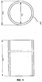
- Fig. 1 shows a flexible tube which may be used in a system according to the present invention.
- the tube has an outer diameter 102, an inner diameter 101 and a tube length 103.
- the tube may be made of a flexible material such as optical grade Silicone.
- Fig. 2 shows the flexible tube 100 inserted into a flattening element 200 comprising a first flattening element 201 and a second flattening element 202.
- the two flattening elements are made of a transparent material such as glass.
- the two flattening elements 201 and 202 are pressed together to flatten the flexible tube 100.
- the flattening of the tube 100 changes the shape of the tube 100 from being circular to an oval-like shape with two parallel flat surfaces.
- a measurement volume 210 comprising first border 211 and second border 212 is defined within the flexible tube 100 between the two parallel surfaces. The distance between the two parallel flat surfaces depends on the force applied by the flattening element 200.
- the position of the first border 211 and the second border 212 do not depend on the distance between the parallel surfaces.
- the size of the measurement volume is therefore changed with the distance of the parallel surfaces. If the distance is small, the measurement volume 210 is small, and if the distance is large, the measurement volume 210 is correspondingly large.
- the measurement volume 210 may thus be adjusted to fit the desired measurement parameters.
- the first flattening element 201 closest to the optical microscope is flat, but other shapes may also be utilized, such as a wedge or a lens. Also other optical elements may be included in the flattening element, such as a polarization filter, density filter or wavelength filter.
- the second flattening element 202 may be flat, but may also have other shapes, such as in embodiments where the second flattening element is optically only used for illuminating the tube 100.
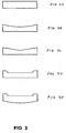
- Fig. 3 different types of a flattening element 202 is shown.
- Fig. 3A a standard flat flattening element 202 is shown, while in Figs. 3B-3E flattening elements 202 comprising a positioning groove 203 is shown.
- Fig. 3B a circular shaped positioning groove is shown.
- Fig. 3C a V-shaped positioning groove is shown, while the positioning groove in Fig. 3D is formed as a recess in the flattening element 202.
- the positioning groove is to help position the flattened tube exactly at the measurement position of the optical microscope.
- the positioning grove may be combined with an optical element, such as a lens, a wedge, a polarization filter, a density filter, a wavelength filter or an aperture as shown in Fig. 3E .
- the combination of a positioning groove and an optical element may be accomplished by selecting the inner wall of the flattening element to be a positioning groove and the outer wall to e.g. have a lens shape (concave or convex). Further, the material of which the flattening element is made may have a filter function.
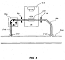
- Fig. 4 the flexible tube 100 is shown in a setup for on-line monitoring of bacteria in tab-water.
- the setup comprises a pipe 500 comprising water from the water works.
- a shunt 510 comprising a flexible tube 100, a tube pump 400, a first clamp 521 and a second clamp 522, and a tube holder 410 comprising a flattening element 200 is connected to the pipe 500 via an inlet 530 and an outlet 540.
- the first clamp 521 is positioned upstream relative to the flattening element 200, while the second clamp 522 is positioned downstream relative to the flattening element 200.
- the first clamp 521 and/or the second clamp 522 may be positioned as close to the flattening element 200 as practical possible so that the volume within the tub between the two clamps is as small as possible. This will decrease the time for the fluid to stop flowing and being ready for measurement.
- the tube pump 400 is activated to suck water at the inlet 530 from the pipe 500 through the flexile tube 100 and to the outlet 540.
- the first clamp 521 and the second clamp 522 should be opened.
- the tube 100 has been filled with water from the pipe 500, and the tube pump 400 is deactivated. It is preferred that the water in the tube 100 is at stand still during measurement, and to ensure this the first clamp 521 and the second clamp 522 is activated to stop the water in the tube to flow.
- the flattening element 200 is now activated to flatten the flexible tube 100, until the required distance between the inner walls of the tube has been achieved.
- the measurement procedure is started.
- the measurement procedure may comprise an optical sectioning of the measurement volume.
- the flattening element may be activated before or during the activation of the pump.
- the flattening element may also be arranged to provide a substantially constant tube thickness during a procedure, wherein a plurality of measurements are performed.
- the distance between the inner walls of the tube should be changed to optimize the measurement procedure. If e.g. it is determined that the concentration of bacteria in the tab water is very low, a larger volume could be measured. The distance between the walls of the tube should therefore be large. If the concentration between to measurements starts to increase, it may be desired to decrease the measurement volume, to get a lower bacteria count. After changing the inner wall distance, the measurement procedure is continued.
- the water in the flexible tube 100 should be replaced with a new sample. This is done by first deactivating the flattening element 200 to release the tube from being flattened, then opening the clamps 521 and 522 and activating the tube pump 400. After a period of time, the water in the flexible tube 100 has been completely replaced with a new sample of water, and the tube pump 400 is be deactivated and the two clamps 521 and 522 is activated to stop the water flow through the flexible tube 100.
- tube pumps There are several different types of tube pumps. If the tube pump is if a type wherein the fluid is completely stopped from flowing when the pump is deactivated, the two clamps 521 and 522 may be omitted.
- the outlet 540 from the flexible tube 100 may be connected to the same pipe as the inlet 530.
- the tube pump may be necessary for replacing the fluid sample in the flexible tube. If the outlet is connected to another pipe or a drain or similar, the tube pump may not be necessary, as the fluid pressure at the inlet compared to the fluid pressure at the outlet may be sufficiently higher to press a new sample into the tube replacing the existing one.
Landscapes
- Health & Medical Sciences (AREA)
- Chemical & Material Sciences (AREA)
- Analytical Chemistry (AREA)
- General Health & Medical Sciences (AREA)
- Immunology (AREA)
- Biochemistry (AREA)
- Life Sciences & Earth Sciences (AREA)
- General Physics & Mathematics (AREA)
- Physics & Mathematics (AREA)
- Pathology (AREA)
- Clinical Laboratory Science (AREA)
- Chemical Kinetics & Catalysis (AREA)
- Hematology (AREA)
- Investigating Or Analysing Materials By Optical Means (AREA)
- Optical Measuring Cells (AREA)
- Microscoopes, Condenser (AREA)
Description
- The present invention relates to a flexible sample container to be used in connection to measuring on fluid samples. The system is suitable for measuring on both large and small quantities of sample fluid, such as in connection to samples comprised of a few micro litres.
- In
US 3,814,522 Clark and Wells disclose a tube and method for using the tube in analysis of urine samples. The tube is made of glass, plastic or other un-flexible transparent material and comprises a circular upper end and a flattened lower end providing two substantially parallel surfaces. The lower end is suitable for use in a microscope for examination of sediments in the flattened portion. The tube is suitable for use together with a centrifuge for concentration of the sediments in the flattened portion. - The suggested tube provides a simple way of applying a sample to a sample holder to be inserted into a microscope for examination of the sample. However, the suggested tube is to be filled using a pipette or similar and after centrifugation and sedimentation the surplus fluid is to be disposed before incision into a microscope. This indicates that the fluid, e.g. urine, is to be manually handled at least two times, exposing the handler for possible diseases and the sample for contamination. Further, the tube is to be inserted into the microscope by hand, making automatic replacement of a tube difficult or impossible.
- In
US 5,672,888 Shaw et al. disclose an optical bubble detector comprising an optics block formed with a V-shaped recess, and a clamp block. The optics block and clamp block cooperatively press or "sandwich" the flexible tubing into the V-shaped recess and deform it into a triangular prismatic cross-section. A generally U-shaped optical interrupter element, containing a photo emitter and a photo sensor, fits into the optics block in such a manner that a light beam is directed radially into the triangular tubing section. The clamp block "windows" the transmitted and received light from the optical interrupter, to allow only a thin channel of light to be transmitted; this minimizes optical noise during measurement. The optical bubble detector is utilized for detecting bubbles in e.g. saline solutions, and there is no imaging of the fluid in the tube during measurement. - In
WO/2006/013312 Chu disclose a fluid detector and alarm system. The invention relates to a fluid detector and in particular to such a system for detecting the presence of a first fluid phase within an administrative system for a second fluid phase. Most particularly, the invention relates to such a system for detecting the presence of air in a liquid administrative system such as those used in the intravenous infusion of fluid in critically ill patients, or to such a system for detecting the presence of liquid within an air-filled system, and for triggering an alarm if air or liquid is inadvertently present in the system. - Also in
WO 2002/084256 an optical bubble detector is disclosed comprising an emitter and a photo detector. The sample cell and the optical sensor use light refraction to determine the presence and size of a bubble passing through the sample cell. - Further, in
WO 1989/001796 a bubble detector is disclosed. In order to detect bubbles in a fluid flowing along a passageway, a portion of the passageway is formed with an elongate cross-section having parallel longer side walls. A first light path passes across the passageway portion and a second light path not passing across the passageway is provided as a reference. When a bubble bigger than the gap between the side walls of the passageway portion passes into the passageway portion, the amount of light passing along the first light path increases and, if the ratio of light passing along the first light path to light passing along the second, reference light path exceeds a predetermined value, a bubble is deemed to have been detected. -
WO 02/075284 - In none of the aforementioned disclosures an optical scanning apparatus is utilized to image the fluid within the tube.
- The present invention provides a system and a method for overcoming at least one of the drawbacks of the tubes as disclosed in the prior art. Specifically, one object of the present invention is to provide a system for holding a fluid sample which is preferably simple to use. The system is defined by claim 1.
- A second object of the present invention is to provide a method for providing a fluid sample to an optical scanning apparatus which preferably results in a high quality of images obtained by scanning and preferably in a fast and simple manner. The method is defined by claim 10.
- One or more of these objects have been solved by the invention and embodiments thereof as defined in the claims and as described below. In the context of the present application, the phrase "flexible" is used to describe one aspect of the physical nature of a tube. A flexible tube may be temporarily deformed by bending, stretching, flattening, compressing, etc, without breaking or leaking, and when released from deformation, the flexible tube substantially returns to the shape it had before being deformed. A flexible tube may be made of Silicone or similar material.
- In the context of the present application the phrase "flexible tube" and "tube" and "sample container" may be used for denoting the same part. In the first state, the cross section of the tube may be substantially circular shaped or it may be substantially oval or similar shaped.
- In the field of optics, transparency is the physical property of allowing light to pass through a material substantially without being modified. It is preferred that the flexible tube utilized in the present invention is made of a substantial transparent material or comprises a transparent window.
- In the context of the present application, the phrase "fluid" is used to describe a substance having a viscosity sufficiently low for enabling it to float or being pumped into or through a tube. A fluid may comprise water, urine, blood, milk and similar liquids or substances as well as solutions comprising them. Cited from wordnetweb.princeton.edu: "A fluid is a continuous amorphous matter that tends to flow and to conform to the outline of its container".
- A clamp should in the present invention be understood as a device which may be used for blocking the flow of a fluid in a vessel or tube by pressing the walls of the tube together, such as a hemostatic clamp.
- In the context of the present application, the phrase "substantially at stand still" refers to a situation, wherein the movement of the particles in an inhomogeneous liquid sample does not affect the determination of the parameters of the sample, such as the parameters of particles in the sample. In one embodiment, substantially at stand still refers to the situation where the movement of the particles in the period of time lapsed in between the acquisition of two adjacent images in a sequence of spatially displaced images should be substantially smaller than the distance between these two adjacent images, such as one tenth of the distance. In one embodiment, substantially at stand still refers to the situation where there is no mass flow of said liquid sample during the acquisition of at least a part of said plurality of images. In one embodiment for imaging cells and their content, the movement of the cell may be limited to an extent whereby sufficiently sharp images of the cell can be obtained so that details relating to e.g. the nuclei can be determined. In embodiments adapted for determining parameters relating to cells, the term "substantially at stand still" thus may mean that the movement of said cells during the acquisition of an image may be limited to the Depth of Field (DOF) or a fraction of DOF, such as one thousandth of the (DOF), such as one hundredth of the DOF, such as one tenth of the DOF, such as one fifth of the DOF, such as one third of the DOF. The DOF may be in the range 0.1 micrometer to 200 micrometers. The movement of the particles in the liquid sample at stand still conditions may hence be less than 0.001 micrometer per second, such as less than 0.01 micrometer per second, , such as less than 0.1 micrometer per second, such as less than 1 micrometer per second. The particle parameter may in this embodiment be the number and size of nuclei or the distance between the nuclei in a cell. In one embodiment where the details of the particle are of less interest, such as for counting particles, the limitation on the particle movement is such that the counting of the particles is not influenced by the movement. The movement of the particles to be counted may hence be less than 0.01 micrometer per second, such as less than 0.1 micrometer per second, , such as less than 1 micrometer per second, such as less than 10 micrometer per second, such as less than 100 micrometer per second, such as less than 1 millimeter per second.
- The system further comprise an optical scanning apparatus for acquiring at least one image from the fluid sample in the transparent flexible tube in the first state and/or in the second state, wherein the fluid sample is at stand still.
- The optical scanning apparatus is adapted to calculate a parameter relating to the fluid sample and from the parameter determine a new state for the flexible tube.
- In one embodiment, the transparent flexible tube in the first state has an inner diameter less than about 25 mm, such as less than about 20 mm, such as less than about 15 mm, such as less than about 10 mm, such as less than about 5 mm, such as less than about 3 mm, such as less than about 2 mm, such as less than about 1.5 mm, such as less than about 1 mm.
- In one embodiment, the flexible tube comprises an inlet for introducing a fluid into the tube. The inlet may be connected to a hose or other type of outlet, or work as a drain to a pipe or catheter or similar.
- In one embodiment, the flexible tube comprises an outlet utilized to remove the fluid present in the tube. The outlet may work as a drain, directing the fluid directly to a waste container or similar,
- In one embodiment, the flexible tube comprises both an inlet and an outlet. The inlet and the outlet may both be connected to the same pipe or catheter. In this way, the tube works as a shunt to the pipe or catheter. The outlet may also work as a drain, directing the fluid directly to a waste container or similar.
- In one embodiment, the system comprises a tube pump adapted to pump fluid into the tube via the inlet. If the tube inlet and tube outlet is connected to the same pipe or catheter it may be necessary to activate a tube pump for pumping fluid into the tube, or for removing fluid present in the tube and replacing the fluid with a new sample. Various types of tube pumps are generally known in the art, and it will be appreciated that any type of tube pump may be used in the system of the present invention. The tube pump may be activated electronically or manually.
- In one embodiment, the system comprises at least a first clamp for clamping said tube. When the tube is clamped, the flow of the fluid through the tube is stopped. When the tube is un-clamped the fluid may flow freely in the tube. Various types of clamps are known in the art, and any type of clamp may be utilized in the system of the present invention as long as the clamping substantially stops the flow in the tube.
- The flattening element may be comprised of any suitable material, such as metal or plastic. In one embodiment, at least one of the flattening elements comprises a substantially transparent region. The transparent region may be utilized for transmitting electromagnetic waves through the flattening element and a tube positioned between the flattening elements. The transparent region of the flattening element may be comprised of a substantially transparent material such as glass or transparent plastic.
- In one embodiment, the transparent region of the flattening elements comprises an inner surface and an outer surface. The inner surface should be understood as being the surface facing the tube, while the outer surface is the surface at the opposite side of the flattening element. In one embodiment, the inner surface is substantially flat. In another embodiment the inner surface comprises a guiding groove. The guiding groove may be utilized to position the tube in a preferred position relating the optical path of the optical microscope. The guiding groove may be shaped as a "V", it may be shaped as an arc, or it may be shaped comprising a flat area in the middle and an elevated area in each side to form a border. A skilled person will appreciate that many different shapes may be used as a guiding groove, and the herein mentioned shapes should only be considered to be examples of these.
- In one embodiment, the transparent region comprises at least one optical element. The optical element may be comprised of a lens, a wedge, a polarizer, an aperture, a color filter, a density and a grating. Other optical elements known in the art may also be utilized. The optical element comprised in the transparent region may form a part of the optical path of the optical microscope.
- In one embodiment, the first flattening element and the second flattening element are moved relatively to each other by utilizing a stepper motor or by a piezo electric motor or similar. Indeed, a skilled person will appreciate, that any type of motor or actuator suitable for micro-mechanics may be used to move the flattening elements relatively to each other.
- In one embodiment, the first flattening element and the second flattening element are moved relatively to each other is such a way that the distances between the rims of the elements are changed uniformly. In one embodiment, the distances between the rims of the elements are changed in such a way, that the change in distance is larger at a first rim area relative to a second rim area. This effect may also be accomplished using a flattening element shaped as a wedge. The wedge effect may be utilized in the longitudinal direction of the tube (along the tube length) and it may be utilized in the transversal direction of the tube (perpendicular to the tube length) as well as a combination thereof.
- In one embodiment, the flattening element may have two or more steps. When utilized to flatten the flexible tube, each step may provide a different measurement volume. This may be utilized when using the flexible tube in connection with an optical scanning device for measuring at least two different parameters relating to the particles in the fluid. The parameters may e.g. be the number of platelets in blood and the number of white blood cells in the blood. For determining the number of platelets in blood, it is advantageous to have a thin measurement volume, while enumeration of white blood cells may advantageously be made in a relatively thicker measurement volume. Utilizing a flattening element comprising two steps, the parameters may be measured in one measurement.
- In one embodiment, the shape of the tube in its second state is such that the distance between the inner wall of a part of the tube being in contact with the first flattening element to the inner wall of a part of the tube being in contact with the second flattening element is less than about 25 mm, such as less than about 20 mm, such as less than about 15 mm, such as less than about 10 mm, such as less than about 5 mm, such as less than about 3 mm, such as less than about 2 mm, such as less than about 1 mm, such as less than about 0.5 mm, such as less than about 0.25 mm, such as less than about 0.1 mm, such as less than about 0.05 mm.
- The method of the present invention comprises providing a fluid sample to an optical microscope. The method comprises arranging a flexible tube in a tube holder and arranging the tube holder in relation to the optical microscope. The flexible tube may be arranged in the tube holder by attaching it to the tube holder, and the tube holder may be attached to the optical microscope. The method further comprises providing the fluid to the flexible tube, and moving a first flattening element and a second flattening element relative to each other thereby changing the transparent flexible tube from a first state to a second state where at least a first cross sectional dimension of said tube is smaller in the second state than in the first state.
- An optical scanning apparatus to be used together with the flexible tube of the present invention may comprise an image acquisition device for acquiring images of the fluid sample comprised in the flexible tube. Further, there may be an image analyzing unit in connection to the optical scanning device and image acquisition device for analyzing images to determine at least one parameter describing particles comprised in the fluid. The parameters may comprise the enumeration of the particles, the concentration of the particles, the morphology of the particles, the turbidity of the fluid or the average size of the particles. Indeed a large number of parameters may be determined to characterize the fluid or the particles within fluid.
- The optical scanning apparatus may be a common optical microscope comprising a digital camera or it may be a more specialized optical scanning apparatus dedicated to acquiring image stacks of fluids comprised in a sample container. In international patent application
PCT/DK/2009/050321 - The system and method of the present invention may be adapted to change the thickness of the tube after each image acquisition. When an image has been acquired and the image analysing device has been invoked to determine the parameter(s) describing the fluid and the contents thereof, the parameter(s) may be used for determining a new optimal tube thickness for the next measurement.
- The method further comprises acquiring at least one image from the optical microscope, determining at least one parameter relating to the fluid from the images, determining a new optimal tube thickness from the parameters and moving the first flattening element and the second flattening element relative to each other until the tube has been flattened to the new optimal tube thickness.
- In one embodiment, the parameter relates to the concentration of particles in the fluid.
-
-
Fig. 1 shows a flexible tube, -
Fig. 2 shows the flexible tube in compressed state, -
Fig. 3 shows different version of a positioning grove, -
Fig. 4 shows the flexible tube in connection with a water pipe - The figures are schematic and may be simplified for clarity. Throughout, the same reference numerals are used for identical or corresponding parts.
-
Fig. 1 shows a flexible tube which may be used in a system according to the present invention. The tube has anouter diameter 102, aninner diameter 101 and atube length 103. The tube may be made of a flexible material such as optical grade Silicone. -
Fig. 2 shows theflexible tube 100 inserted into a flatteningelement 200 comprising afirst flattening element 201 and asecond flattening element 202. The two flattening elements are made of a transparent material such as glass. After theflexible tube 100 has been inserted into the flatteningelement 200, the two flatteningelements flexible tube 100. The flattening of thetube 100 changes the shape of thetube 100 from being circular to an oval-like shape with two parallel flat surfaces. Ameasurement volume 210 comprisingfirst border 211 andsecond border 212 is defined within theflexible tube 100 between the two parallel surfaces. The distance between the two parallel flat surfaces depends on the force applied by the flatteningelement 200. The position of thefirst border 211 and thesecond border 212 do not depend on the distance between the parallel surfaces. The size of the measurement volume is therefore changed with the distance of the parallel surfaces. If the distance is small, themeasurement volume 210 is small, and if the distance is large, themeasurement volume 210 is correspondingly large. Themeasurement volume 210 may thus be adjusted to fit the desired measurement parameters. - In the embodiment illustrated in
Figure 2 , thefirst flattening element 201 closest to the optical microscope is flat, but other shapes may also be utilized, such as a wedge or a lens. Also other optical elements may be included in the flattening element, such as a polarization filter, density filter or wavelength filter. - The
second flattening element 202 may be flat, but may also have other shapes, such as in embodiments where the second flattening element is optically only used for illuminating thetube 100. InFig. 3 different types of a flatteningelement 202 is shown. InFig. 3A a standardflat flattening element 202 is shown, while inFigs. 3B- 3E flattening elements 202 comprising a positioning groove 203 is shown. InFig. 3B a circular shaped positioning groove is shown. InFig. 3C a V-shaped positioning groove is shown, while the positioning groove inFig. 3D is formed as a recess in the flatteningelement 202. The purpose of the positioning groove is to help position the flattened tube exactly at the measurement position of the optical microscope. The positioning grove may be combined with an optical element, such as a lens, a wedge, a polarization filter, a density filter, a wavelength filter or an aperture as shown inFig. 3E . The combination of a positioning groove and an optical element may be accomplished by selecting the inner wall of the flattening element to be a positioning groove and the outer wall to e.g. have a lens shape (concave or convex). Further, the material of which the flattening element is made may have a filter function. - In
Fig. 4 theflexible tube 100 is shown in a setup for on-line monitoring of bacteria in tab-water. The setup comprises apipe 500 comprising water from the water works. Ashunt 510 comprising aflexible tube 100, atube pump 400, afirst clamp 521 and asecond clamp 522, and atube holder 410 comprising a flatteningelement 200 is connected to thepipe 500 via aninlet 530 and anoutlet 540. Thefirst clamp 521 is positioned upstream relative to the flatteningelement 200, while thesecond clamp 522 is positioned downstream relative to the flatteningelement 200. Thefirst clamp 521 and/or thesecond clamp 522 may be positioned as close to the flatteningelement 200 as practical possible so that the volume within the tub between the two clamps is as small as possible. This will decrease the time for the fluid to stop flowing and being ready for measurement. - The
tube pump 400 is activated to suck water at theinlet 530 from thepipe 500 through theflexile tube 100 and to theoutlet 540. During operation of the tube pump, thefirst clamp 521 and thesecond clamp 522 should be opened. After activation of thetube pump 400 for a period of time, thetube 100 has been filled with water from thepipe 500, and thetube pump 400 is deactivated. It is preferred that the water in thetube 100 is at stand still during measurement, and to ensure this thefirst clamp 521 and thesecond clamp 522 is activated to stop the water in the tube to flow. - The flattening
element 200 is now activated to flatten theflexible tube 100, until the required distance between the inner walls of the tube has been achieved. When this is accomplished, the measurement procedure is started. The measurement procedure may comprise an optical sectioning of the measurement volume. - For some applications, the flattening element may be activated before or during the activation of the pump. The flattening element may also be arranged to provide a substantially constant tube thickness during a procedure, wherein a plurality of measurements are performed.
- During the measurement procedure, it may be determined that the distance between the inner walls of the tube should be changed to optimize the measurement procedure. If e.g. it is determined that the concentration of bacteria in the tab water is very low, a larger volume could be measured. The distance between the walls of the tube should therefore be large. If the concentration between to measurements starts to increase, it may be desired to decrease the measurement volume, to get a lower bacteria count. After changing the inner wall distance, the measurement procedure is continued.
- After the measurement procedure has been completed, the water in the
flexible tube 100 should be replaced with a new sample. This is done by first deactivating the flatteningelement 200 to release the tube from being flattened, then opening theclamps tube pump 400. After a period of time, the water in theflexible tube 100 has been completely replaced with a new sample of water, and thetube pump 400 is be deactivated and the twoclamps flexible tube 100. - There are several different types of tube pumps. If the tube pump is if a type wherein the fluid is completely stopped from flowing when the pump is deactivated, the two
clamps - The
outlet 540 from theflexible tube 100 may be connected to the same pipe as theinlet 530. In this case, the tube pump may be necessary for replacing the fluid sample in the flexible tube. If the outlet is connected to another pipe or a drain or similar, the tube pump may not be necessary, as the fluid pressure at the inlet compared to the fluid pressure at the outlet may be sufficiently higher to press a new sample into the tube replacing the existing one. - Some preferred embodiments have been shown in the foregoing, but it should be stressed that the invention is not limited to these, but may be embodied in other ways within the subject-matter defined in the following claims.
Claims (13)
- A system for holding a fluid ample, comprising:- a transparent flexible tube (100) or holding said fluid sample;- a tube holder for holding said tube;- a first flattening element (201);- a second flattening element (202);wherein said first flattening element (201) and said second flattening element (202) can be moved relative to each other thereby changing said transparent flexible tube from a first state to a second state, where at least a first cross sectional dimension of said tube is smaller in said second state than in said first state,
characterised in that said system further comprises an optical scanning apparatus comprising an image acquisition device for acquiring images of the fluid sample comprised in the flexible tube at least in the second state,
wherein said optical scanning apparatus is adapted to calculate a parameter relating to particles comprised in said fluid sample and from said parameter determine a new state for said flexible tube, wherein said parameter is chosen from the group of parameters consisting of: the number of the particles, the concentrations of the particles. - The system according to claim 1, wherein said transparent flexible tube (100) in a first state has an inner diameter (101) than about 25 mm, such as less than about 20 mm, such as less than about 15 mm, such as less than about 10 mm, such as less than about 5 mm, such as less than about 3 mm, such as less than about 2 mm, such as less than about 1.5 mm, such as less than about 1 mm.
- The system according to any one of claims 1 to 2, wherein said flexible tube (100) comprises an inlet (530) and/or an outlet (540), and said system preferably further comprising a tube pump (400) adapted to pump fluid into said tube via said inlet.
- The system according to any one of claims 1 to 3, further comprising at least a first clamp (521) for clamping said tube (100).
- The system according to any one of claims 1 to 4, wherein at least one of said flattening elements (201, 202) comprises a transparent region.
- The system according to claim 5, wherein said transparent region comprises an inner surface and an outer surface.
- The system according to claim 6, wherein said inner surface is substantially flat.
- The system according to claim 6, wherein said inner surface comprises a guiding groove (203).
- The system according to any one of claims 6 to 8, wherein said transparent region comprises at least one optical element selected from a lens, a wedge, a polarizer, an aperture, a filter and a grating.
- The system according to any one of claims 8 to 9, wherein the activation of the flattening element (201, 202) is such that the distance between the inner walls of said flattened tube is less than about 25 mm, such as less than about 20 mm, such as less than about 15 mm, such as less than about 10 mm, such as less than about 5 mm, such as less than about 3 mm, such as less than about 2 mm, such as less than about 1.0 mm, such as less than about 0.5 mm, such as less than about 0.25 mm, such as less than about 0.1 mm, such as less than about 0.05 mm.
- A method for providing a fluid sample to an optical scanning apparatus, comprising:- arranging a transparent flexible tuber (100) in a tube holder;- arranging said tube holder in relation to said optical scanning apparatus;- providing fluid to said tube;- moving a first flattening element (201) and a second flattening element (202) relative to each other thereby changing said transparent flexible tube (100) from a first state to a second state, where at least a first cross sectional dimension of said tube is smaller in the second state than in the first state, and acquiring at least one image from the fluid sample in the transparent flexible tube at least in the second state using said optical scanning apparatus- determining at least one parameter relating to particles comprised said fluid from said image, wherein said parameter is chosen from the group of parameters consisting of: the number of the particles, the concentrations of the particles;- determining a new tube thickness from said one parameter;- moving said first flattening element (201) and said second flattening element (202) relative to each other thereby changing said transparent flexible tube to a third state.
- The method according to claim 11, wherein said one parameter relates to the concentration of particles in said fluid.
- The method according to any one of claims 11 to 12, wherein said optical apparatus is an optical scanning apparatus adapted to scan an image plane through at least a part of said tube to obtain a plurality of images of the sample arranged therein, and/or to acquire at least one image from said fluid sample in said transparent flexible tube in said first state and/or in said second state, wherein said fluid sample is substantially at stand still.
Applications Claiming Priority (3)
| Application Number | Priority Date | Filing Date | Title |
|---|---|---|---|
| US31049910P | 2010-03-04 | 2010-03-04 | |
| DKPA201000170 | 2010-03-04 | ||
| PCT/DK2011/050064 WO2011107102A1 (en) | 2010-03-04 | 2011-03-02 | Flexible sample container |
Publications (3)
| Publication Number | Publication Date |
|---|---|
| EP2542878A1 EP2542878A1 (en) | 2013-01-09 |
| EP2542878A4 EP2542878A4 (en) | 2014-07-16 |
| EP2542878B1 true EP2542878B1 (en) | 2016-09-14 |
Family
ID=44541667
Family Applications (1)
| Application Number | Title | Priority Date | Filing Date |
|---|---|---|---|
| EP11750218.7A Active EP2542878B1 (en) | 2010-03-04 | 2011-03-02 | Flexible sample container |
Country Status (10)
| Country | Link |
|---|---|
| US (1) | US9250176B2 (en) |
| EP (1) | EP2542878B1 (en) |
| JP (1) | JP5769116B2 (en) |
| KR (1) | KR20130054240A (en) |
| CN (1) | CN102792148B (en) |
| AU (1) | AU2011223342B2 (en) |
| BR (1) | BR112012022130A2 (en) |
| CA (1) | CA2791428A1 (en) |
| RU (1) | RU2557603C2 (en) |
| WO (1) | WO2011107102A1 (en) |
Families Citing this family (22)
| Publication number | Priority date | Publication date | Assignee | Title |
|---|---|---|---|---|
| RU2548597C2 (en) | 2009-12-04 | 2015-04-20 | Юнисенсор А/С | System and method for time-related microscopy of biological organisms |
| JP2013148521A (en) * | 2012-01-20 | 2013-08-01 | Sumitomo Electric Ind Ltd | Sample measuring cell, physical property measurement device, and physical property measurement method |
| US8906320B1 (en) * | 2012-04-16 | 2014-12-09 | Illumina, Inc. | Biosensors for biological or chemical analysis and systems and methods for same |
| JP6264741B2 (en) * | 2013-04-16 | 2018-01-24 | 横河電機株式会社 | Spectroscopic analyzer |
| JP6426704B2 (en) * | 2013-04-19 | 2018-11-21 | コーニンクレッカ フィリップス エヌ ヴェKoninklijke Philips N.V. | Optical system and method for real time analysis of liquid samples |
| EP3004820B1 (en) * | 2013-05-27 | 2017-03-29 | GasPorOx AB | System and method for determining a concentration of a gas in a container |
| JP5672342B2 (en) | 2013-07-09 | 2015-02-18 | 東洋製罐グループホールディングス株式会社 | Counting device |
| JP6147619B2 (en) | 2013-09-09 | 2017-06-14 | 株式会社日立製作所 | Cell culture device and cell culture method |
| US20180014770A1 (en) * | 2014-12-15 | 2018-01-18 | Drugster Aps | Measurement Device, Measurement Tube and the Use Thereof for Monitoring of Urine Flow |
| RU2726061C2 (en) | 2014-12-22 | 2020-07-08 | Реналсенс Лтд. | Methods, device and system for urine analysis |
| US9678016B2 (en) | 2015-01-23 | 2017-06-13 | J.M. Canty Inc | Flow analyzer for harsh environments |
| EP3440449A4 (en) * | 2016-04-08 | 2019-11-27 | Veriphi Limited | Sample receptacle for spectrophotometry |
| FR3051045B1 (en) * | 2016-05-04 | 2020-11-20 | Ipratech Sa | CONTAINMENT DEVICE WITH A VARIABLE SIZE MEASURING CHAMBER BOUNDED IN PART BY A FLEXIBLE MEMBRANE |
| US10782282B2 (en) * | 2016-05-27 | 2020-09-22 | Chin-Hsing CHUO | Microorganism detection system |
| CN107907471A (en) * | 2017-10-26 | 2018-04-13 | 刘峰 | A kind of cellular assay counting device |
| JP6986266B2 (en) * | 2017-11-14 | 2021-12-22 | ジーニアルライト株式会社 | Body fluid analyzer |
| TWI700489B (en) * | 2018-10-29 | 2020-08-01 | 林修安 | Device for instantaneously inspecting waste quality and recovery device and method using the same |
| WO2021086746A1 (en) * | 2019-10-28 | 2021-05-06 | North Carolina State University | Reduced pathlength flow cell for inline sample characterization in modular fluoropolymer tubing microfluidics |
| EP4107509A1 (en) | 2020-02-21 | 2022-12-28 | Ecolab USA Inc. | Modular optical sensor |
| US20230347036A1 (en) * | 2020-07-08 | 2023-11-02 | I--Sep | Device For Determining The Level Of Haemoglobin Or Haematocrit Of A Circulating Liquid |
| FR3112391A1 (en) * | 2020-07-08 | 2022-01-14 | I Sep | Apparatus for determining the hemoglobin or hematocrit level of a circulating fluid |
| JP7250978B1 (en) * | 2022-04-19 | 2023-04-03 | ニプロ株式会社 | Fluid concentration measuring device |
Citations (1)
| Publication number | Priority date | Publication date | Assignee | Title |
|---|---|---|---|---|
| EP0614077A2 (en) * | 1993-01-26 | 1994-09-07 | Hitachi, Ltd. | Flow cell apparatus |
Family Cites Families (76)
| Publication number | Priority date | Publication date | Assignee | Title |
|---|---|---|---|---|
| GB1418181A (en) | 1973-02-27 | 1975-12-17 | Cole E M | Ultrasonic detection of inclusions in a fluid flowing within a tube |
| US3814522A (en) | 1973-02-28 | 1974-06-04 | American Hospital Supply Corp | Specimen tube for microscopic examination |
| US4448534A (en) | 1978-03-30 | 1984-05-15 | American Hospital Corporation | Antibiotic susceptibility testing |
| GB2182432B (en) | 1985-10-30 | 1989-10-25 | Edmund Miles Rank | Improvements in and relating to apparatus for detecting particles in suspension |
| GB8720454D0 (en) * | 1987-08-28 | 1987-10-07 | Bellhouse Techn Ltd | Bubble detector |
| JPH061152Y2 (en) | 1989-04-28 | 1994-01-12 | シャープ株式会社 | Infusion pump air detector |
| US5123275A (en) * | 1990-12-07 | 1992-06-23 | Ivac Corporation | Air in-line sensor system |
| US5393494A (en) * | 1992-05-28 | 1995-02-28 | Diasys Corporation | Apparatus for drawing fluid sample, components thereof, and slide assembly for use therewith |
| US5329461A (en) | 1992-07-23 | 1994-07-12 | Acrogen, Inc. | Digital analyte detection system |
| JP2003161691A (en) * | 1993-01-26 | 2003-06-06 | Hitachi Ltd | Flow cell device |
| US5649032A (en) | 1994-11-14 | 1997-07-15 | David Sarnoff Research Center, Inc. | System for automatically aligning images to form a mosaic image |
| US5672887A (en) * | 1995-11-29 | 1997-09-30 | Shaw; Benjamin G. | Optical detector for air in fluid line the same |
| JP2720862B2 (en) | 1995-12-08 | 1998-03-04 | 日本電気株式会社 | Thin film transistor and thin film transistor array |
| US6008010A (en) | 1996-11-01 | 1999-12-28 | University Of Pittsburgh | Method and apparatus for holding cells |
| JPH10161034A (en) | 1996-12-02 | 1998-06-19 | Nikon Corp | Confocal microscope and method for forming three-dimensional image by using the same confocal microscope |
| IL132688A (en) | 1997-05-05 | 2005-08-31 | Chemometec As | Method and system for determination of particles in a liquid sample |
| US5868712A (en) * | 1997-06-12 | 1999-02-09 | Abbott Laboratories | Pump with door-mounted mechanism for positioning tubing in the pump housing |
| US5939709A (en) | 1997-06-19 | 1999-08-17 | Ghislain; Lucien P. | Scanning probe optical microscope using a solid immersion lens |
| US6929953B1 (en) | 1998-03-07 | 2005-08-16 | Robert A. Levine | Apparatus for analyzing biologic fluids |
| US6313452B1 (en) | 1998-06-10 | 2001-11-06 | Sarnoff Corporation | Microscopy system utilizing a plurality of images for enhanced image processing capabilities |
| US6153400A (en) | 1999-03-12 | 2000-11-28 | Akzo Nobel N.V. | Device and method for microbial antibiotic susceptibility testing |
| US6867851B2 (en) | 1999-11-04 | 2005-03-15 | Regents Of The University Of Minnesota | Scanning of biological samples |
| US6656683B1 (en) | 2000-07-05 | 2003-12-02 | Board Of Regents, The University Of Texas System | Laser scanning cytology with digital image capture |
| US6489896B1 (en) | 2000-11-03 | 2002-12-03 | Baxter International Inc. | Air in-line sensor for ambulatory drug infusion pump |
| US7194118B1 (en) | 2000-11-10 | 2007-03-20 | Lucid, Inc. | System for optically sectioning and mapping surgically excised tissue |
| WO2002075284A2 (en) | 2001-03-20 | 2002-09-26 | Abb Bomem Inc. | Flow-through cell |
| JP3661604B2 (en) | 2001-04-05 | 2005-06-15 | 松下電器産業株式会社 | Microscopic observation apparatus and microscopic observation method |
| US6531708B1 (en) | 2001-04-16 | 2003-03-11 | Zevex, Inc. | Optical bubble detection system |
| US7058233B2 (en) | 2001-05-30 | 2006-06-06 | Mitutoyo Corporation | Systems and methods for constructing an image having an extended depth of field |
| US7248716B2 (en) | 2001-07-06 | 2007-07-24 | Palantyr Research, Llc | Imaging system, methodology, and applications employing reciprocal space optical design |
| WO2003019161A1 (en) | 2001-08-23 | 2003-03-06 | D.N.R. - Imaging Systems Ltd. | Optical system and method for inspecting fluorescently labeled biological specimens |
| JP2003065952A (en) * | 2001-08-24 | 2003-03-05 | Kosu:Kk | Dissolved-ozone concentration meter |
| EP1438582A1 (en) | 2001-09-16 | 2004-07-21 | ChemoMetec A/S | Method and a system for detecting and optionally isolating a rare event particle |
| US20030059866A1 (en) | 2001-09-26 | 2003-03-27 | Kim Lewis | Isolation and cultivation of microorganisms from natural environments and drug discovery based thereon |
| GB0127914D0 (en) * | 2001-11-21 | 2002-01-16 | Elan Vital Uk Ltd | Fluid receptacles |
| US20030103277A1 (en) | 2001-12-05 | 2003-06-05 | Mohwinkel Clifford A. | Imaging device with angle-compensated focus |
| AU2002351400A1 (en) | 2001-12-28 | 2003-07-24 | Applied Precision, Llc | Dual-axis scanning system and method |
| US7231081B2 (en) | 2001-12-28 | 2007-06-12 | Applied Precision, Llc | Stereoscopic three-dimensional metrology system and method |
| US7764821B2 (en) | 2002-02-14 | 2010-07-27 | Veridex, Llc | Methods and algorithms for cell enumeration in a low-cost cytometer |
| US6873725B2 (en) | 2002-09-09 | 2005-03-29 | Coulter International Corp. | Simultaneous measurement and display of 3-D size distributions of particulate materials in suspensions |
| RU2232988C2 (en) | 2002-10-03 | 2004-07-20 | Дальневосточный государственный медицинский университет | Method for estimation of content of blood leukocytes, erythrocytes and platelets taking into account heme concentration |
| US7345814B2 (en) | 2003-09-29 | 2008-03-18 | Olympus Corporation | Microscope system and microscope focus maintaining device for the same |
| US20050259437A1 (en) | 2004-05-19 | 2005-11-24 | Klein Gerald L | Apparatus, systems and methods relating to illumination for microscopes |
| GB0417337D0 (en) * | 2004-08-04 | 2004-09-08 | Chu Andrew C | Low cost air bubble detector and alarm system for fluid administrative applications |
| US20060084125A1 (en) | 2004-10-18 | 2006-04-20 | Herzel Laor | Methods, devices, and systems for detection of cancer |
| GB0426609D0 (en) | 2004-12-03 | 2005-01-05 | Ic Innovations Ltd | Analysis |
| JP4677251B2 (en) * | 2005-02-25 | 2011-04-27 | 倉敷紡績株式会社 | Flow cell, flow cell manufacturing method, and fluid concentration measuring apparatus |
| US7718131B2 (en) | 2005-07-06 | 2010-05-18 | Genetix Limited | Methods and apparatus for imaging and processing of samples in biological sample containers |
| DE102005046755A1 (en) | 2005-09-29 | 2007-04-19 | Carl Zeiss Jena Gmbh | Apparatus and method for generating an image of an object |
| US7731901B2 (en) | 2005-10-19 | 2010-06-08 | Abbott Laboratories | Apparatus and method for performing counts within a biologic fluid sample |
| JP4923541B2 (en) | 2005-11-30 | 2012-04-25 | 株式会社ニコン | microscope |
| CN1979138A (en) * | 2005-12-09 | 2007-06-13 | 李炳寰 | Sample box for electronic microscope for observing general sample/living cell |
| WO2007095090A2 (en) | 2006-02-10 | 2007-08-23 | Monogen, Inc. | Method and apparatus and computer program product for collecting digital image data from microscope media-based specimens |
| JP4878913B2 (en) | 2006-05-24 | 2012-02-15 | オリンパス株式会社 | Microscope system, microscope image synthesis method, and program |
| JP5010180B2 (en) * | 2006-05-31 | 2012-08-29 | 京セラドキュメントソリューションズ株式会社 | Liquid developer concentration measuring apparatus and wet image forming apparatus having the same |
| DE102006029899B4 (en) * | 2006-06-29 | 2009-06-04 | Fresenius Medical Care Deutschland Gmbh | Spectroscopic detector and method for the determination of blood and biological markers in liquids |
| CN101097206A (en) * | 2006-06-30 | 2008-01-02 | 赵化平 | Method for rapid inspecting animalcule in liquid |
| US7481114B2 (en) * | 2006-07-13 | 2009-01-27 | Lynnworth Lawrence C | Noninvasive measurement of fluid characteristics using reversibly deformed conduit |
| SE530750C2 (en) * | 2006-07-19 | 2008-09-02 | Hemocue Ab | A measuring device, a method and a computer program |
| US7865007B2 (en) | 2006-10-30 | 2011-01-04 | Olympus Corporation | Microscope system, observation method and observation program |
| US7661294B2 (en) * | 2007-09-21 | 2010-02-16 | Cosense, Inc. | Non-invasive multi-function sensor system |
| JP5013410B2 (en) * | 2007-03-14 | 2012-08-29 | 独立行政法人産業技術総合研究所 | Fine particle measuring method and apparatus |
| US7576307B2 (en) | 2007-04-30 | 2009-08-18 | General Electric Company | Microscope with dual image sensors for rapid autofocusing |
| US8059336B2 (en) | 2007-05-04 | 2011-11-15 | Aperio Technologies, Inc. | Rapid microscope scanner for volume image acquisition |
| US7541807B2 (en) | 2007-07-19 | 2009-06-02 | Varian, Inc. | Rotor drive apparatus and methods utilizing center-fed radial-outflow gas |
| US7630628B2 (en) | 2007-07-27 | 2009-12-08 | Nikon Corporation | Microscope system and microscope observation method |
| JP5068121B2 (en) | 2007-08-27 | 2012-11-07 | 株式会社ミツトヨ | Microscope and three-dimensional information acquisition method |
| JP4509166B2 (en) * | 2007-11-02 | 2010-07-21 | ソニー株式会社 | Method and apparatus for measuring fine particles |
| JP5100360B2 (en) | 2007-12-21 | 2012-12-19 | 株式会社トプコン | Image processing device |
| EP2225598A1 (en) | 2007-12-21 | 2010-09-08 | Koninklijke Philips Electronics N.V. | Scanning microscope and method of imaging a sample. |
| DE102008000504A1 (en) * | 2008-03-04 | 2009-09-17 | Agilent Technologies Inc., Santa Clara | Capillary tube for guiding fluid, is partly extended along optical path and is arranged between source of light and receiver, where two sections are provided with two diameters |
| US8105269B2 (en) * | 2008-10-24 | 2012-01-31 | Baxter International Inc. | In situ tubing measurements for infusion pumps |
| EP2186855A1 (en) * | 2008-11-14 | 2010-05-19 | Total Petrochemicals Research Feluy | A polyolefin composition for the production of an article having a controlled degradation, an article comprising said composition and a process for the production of said article. |
| DK200801722A (en) | 2008-12-05 | 2010-06-06 | Unisensor As | Optical sectioning of a sample and detection of particles in a sample |
| US8149401B2 (en) | 2009-02-13 | 2012-04-03 | Velcon Filters, Llc | System and method for distinguishing particles in a transient fluid |
| RU2548597C2 (en) | 2009-12-04 | 2015-04-20 | Юнисенсор А/С | System and method for time-related microscopy of biological organisms |
-
2011
- 2011-03-02 CN CN201180012265.8A patent/CN102792148B/en not_active Expired - Fee Related
- 2011-03-02 JP JP2012555295A patent/JP5769116B2/en not_active Expired - Fee Related
- 2011-03-02 AU AU2011223342A patent/AU2011223342B2/en not_active Ceased
- 2011-03-02 KR KR1020127025636A patent/KR20130054240A/en not_active Application Discontinuation
- 2011-03-02 US US13/582,593 patent/US9250176B2/en not_active Expired - Fee Related
- 2011-03-02 BR BR112012022130A patent/BR112012022130A2/en not_active IP Right Cessation
- 2011-03-02 RU RU2012142187/05A patent/RU2557603C2/en active
- 2011-03-02 WO PCT/DK2011/050064 patent/WO2011107102A1/en active Application Filing
- 2011-03-02 CA CA2791428A patent/CA2791428A1/en not_active Abandoned
- 2011-03-02 EP EP11750218.7A patent/EP2542878B1/en active Active
Patent Citations (1)
| Publication number | Priority date | Publication date | Assignee | Title |
|---|---|---|---|---|
| EP0614077A2 (en) * | 1993-01-26 | 1994-09-07 | Hitachi, Ltd. | Flow cell apparatus |
Also Published As
| Publication number | Publication date |
|---|---|
| US9250176B2 (en) | 2016-02-02 |
| RU2012142187A (en) | 2014-04-10 |
| EP2542878A4 (en) | 2014-07-16 |
| JP2013521477A (en) | 2013-06-10 |
| CN102792148A (en) | 2012-11-21 |
| BR112012022130A2 (en) | 2016-10-25 |
| JP5769116B2 (en) | 2015-08-26 |
| EP2542878A1 (en) | 2013-01-09 |
| KR20130054240A (en) | 2013-05-24 |
| AU2011223342A1 (en) | 2012-09-20 |
| CN102792148B (en) | 2016-06-01 |
| RU2557603C2 (en) | 2015-07-27 |
| US20120327404A1 (en) | 2012-12-27 |
| CA2791428A1 (en) | 2011-09-09 |
| WO2011107102A1 (en) | 2011-09-09 |
| AU2011223342B2 (en) | 2014-06-05 |
Similar Documents
| Publication | Publication Date | Title |
|---|---|---|
| EP2542878B1 (en) | Flexible sample container | |
| US8064063B2 (en) | Optical characterisation methods and systems | |
| US6825926B2 (en) | Flow cell for urinalysis diagnostic system and method of making same | |
| US7738101B2 (en) | Systems and methods for in-line monitoring of particles in opaque flows | |
| US5764356A (en) | Trace liquid detecting and analyzing device | |
| EP2226623A1 (en) | Flow cell | |
| US20170082602A1 (en) | Systems and Methods for Analyzing Liquids | |
| US8665439B2 (en) | Method and apparatus for limiting effects of refraction in cytometry | |
| IT201800004630A1 (en) | APPARATUS AND PROCEDURE FOR DETERMINING THE SPEED OF BLOOD SEDIMENTATION AND OTHER PARAMETERS RELATED TO IT | |
| JP7305720B2 (en) | Refractometer with single-use prism and reusable optics | |
| EP3452807B1 (en) | Analysis system comprising a confinement device having a measurement chamber of variable size delimited in part by a flexible membrane | |
| WO2022038376A1 (en) | H-type filter device for analysing a component | |
| JP2008070245A (en) | Flow cell for fluid sample | |
| KR20220018000A (en) | Line Volume Calibration System and Method | |
| CA2981647C (en) | Photoacoustic flow cell for identification of rare analytes in suspension | |
| JP7170804B2 (en) | Method and apparatus for measuring analyte concentration in whole blood | |
| CN115835816A (en) | Measuring particle density in a fluid in a pipe | |
| CA2766034A1 (en) | Method and apparatus for limiting effects of refraction in cytometry | |
| JPH02232549A (en) | Photometer measuring apparatus for effluent from centrifugal extractor | |
| JPH02213746A (en) | Device for inspecting sample |
Legal Events
| Date | Code | Title | Description |
|---|---|---|---|
| PUAI | Public reference made under article 153(3) epc to a published international application that has entered the european phase |
Free format text: ORIGINAL CODE: 0009012 |
|
| 17P | Request for examination filed |
Effective date: 20120905 |
|
| AK | Designated contracting states |
Kind code of ref document: A1 Designated state(s): AL AT BE BG CH CY CZ DE DK EE ES FI FR GB GR HR HU IE IS IT LI LT LU LV MC MK MT NL NO PL PT RO RS SE SI SK SM TR |
|
| DAX | Request for extension of the european patent (deleted) | ||
| A4 | Supplementary search report drawn up and despatched |
Effective date: 20140616 |
|
| RIC1 | Information provided on ipc code assigned before grant |
Ipc: G01N 21/05 20060101AFI20140610BHEP Ipc: B01L 3/00 20060101ALI20140610BHEP Ipc: G01N 21/85 20060101ALI20140610BHEP |
|
| 17Q | First examination report despatched |
Effective date: 20150417 |
|
| RAP1 | Party data changed (applicant data changed or rights of an application transferred) |
Owner name: KONINKLIJKE PHILIPS N.V. |
|
| GRAP | Despatch of communication of intention to grant a patent |
Free format text: ORIGINAL CODE: EPIDOSNIGR1 |
|
| INTG | Intention to grant announced |
Effective date: 20160408 |
|
| GRAS | Grant fee paid |
Free format text: ORIGINAL CODE: EPIDOSNIGR3 |
|
| GRAA | (expected) grant |
Free format text: ORIGINAL CODE: 0009210 |
|
| AK | Designated contracting states |
Kind code of ref document: B1 Designated state(s): AL AT BE BG CH CY CZ DE DK EE ES FI FR GB GR HR HU IE IS IT LI LT LU LV MC MK MT NL NO PL PT RO RS SE SI SK SM TR |
|
| REG | Reference to a national code |
Ref country code: GB Ref legal event code: FG4D |
|
| REG | Reference to a national code |
Ref country code: CH Ref legal event code: EP |
|
| REG | Reference to a national code |
Ref country code: IE Ref legal event code: FG4D |
|
| REG | Reference to a national code |
Ref country code: AT Ref legal event code: REF Ref document number: 829525 Country of ref document: AT Kind code of ref document: T Effective date: 20161015 |
|
| REG | Reference to a national code |
Ref country code: DE Ref legal event code: R096 Ref document number: 602011030358 Country of ref document: DE |
|
| REG | Reference to a national code |
Ref country code: LT Ref legal event code: MG4D |
|
| REG | Reference to a national code |
Ref country code: NL Ref legal event code: MP Effective date: 20160914 |
|
| PG25 | Lapsed in a contracting state [announced via postgrant information from national office to epo] |
Ref country code: RS Free format text: LAPSE BECAUSE OF FAILURE TO SUBMIT A TRANSLATION OF THE DESCRIPTION OR TO PAY THE FEE WITHIN THE PRESCRIBED TIME-LIMIT Effective date: 20160914 Ref country code: NO Free format text: LAPSE BECAUSE OF FAILURE TO SUBMIT A TRANSLATION OF THE DESCRIPTION OR TO PAY THE FEE WITHIN THE PRESCRIBED TIME-LIMIT Effective date: 20161214 Ref country code: HR Free format text: LAPSE BECAUSE OF FAILURE TO SUBMIT A TRANSLATION OF THE DESCRIPTION OR TO PAY THE FEE WITHIN THE PRESCRIBED TIME-LIMIT Effective date: 20160914 Ref country code: LT Free format text: LAPSE BECAUSE OF FAILURE TO SUBMIT A TRANSLATION OF THE DESCRIPTION OR TO PAY THE FEE WITHIN THE PRESCRIBED TIME-LIMIT Effective date: 20160914 Ref country code: FI Free format text: LAPSE BECAUSE OF FAILURE TO SUBMIT A TRANSLATION OF THE DESCRIPTION OR TO PAY THE FEE WITHIN THE PRESCRIBED TIME-LIMIT Effective date: 20160914 |
|
| REG | Reference to a national code |
Ref country code: AT Ref legal event code: MK05 Ref document number: 829525 Country of ref document: AT Kind code of ref document: T Effective date: 20160914 |
|
| PG25 | Lapsed in a contracting state [announced via postgrant information from national office to epo] |
Ref country code: LV Free format text: LAPSE BECAUSE OF FAILURE TO SUBMIT A TRANSLATION OF THE DESCRIPTION OR TO PAY THE FEE WITHIN THE PRESCRIBED TIME-LIMIT Effective date: 20160914 Ref country code: NL Free format text: LAPSE BECAUSE OF FAILURE TO SUBMIT A TRANSLATION OF THE DESCRIPTION OR TO PAY THE FEE WITHIN THE PRESCRIBED TIME-LIMIT Effective date: 20160914 Ref country code: SE Free format text: LAPSE BECAUSE OF FAILURE TO SUBMIT A TRANSLATION OF THE DESCRIPTION OR TO PAY THE FEE WITHIN THE PRESCRIBED TIME-LIMIT Effective date: 20160914 Ref country code: GR Free format text: LAPSE BECAUSE OF FAILURE TO SUBMIT A TRANSLATION OF THE DESCRIPTION OR TO PAY THE FEE WITHIN THE PRESCRIBED TIME-LIMIT Effective date: 20161215 |
|
| REG | Reference to a national code |
Ref country code: FR Ref legal event code: PLFP Year of fee payment: 7 |
|
| PG25 | Lapsed in a contracting state [announced via postgrant information from national office to epo] |
Ref country code: EE Free format text: LAPSE BECAUSE OF FAILURE TO SUBMIT A TRANSLATION OF THE DESCRIPTION OR TO PAY THE FEE WITHIN THE PRESCRIBED TIME-LIMIT Effective date: 20160914 Ref country code: RO Free format text: LAPSE BECAUSE OF FAILURE TO SUBMIT A TRANSLATION OF THE DESCRIPTION OR TO PAY THE FEE WITHIN THE PRESCRIBED TIME-LIMIT Effective date: 20160914 |
|
| PG25 | Lapsed in a contracting state [announced via postgrant information from national office to epo] |
Ref country code: IS Free format text: LAPSE BECAUSE OF FAILURE TO SUBMIT A TRANSLATION OF THE DESCRIPTION OR TO PAY THE FEE WITHIN THE PRESCRIBED TIME-LIMIT Effective date: 20170114 Ref country code: SM Free format text: LAPSE BECAUSE OF FAILURE TO SUBMIT A TRANSLATION OF THE DESCRIPTION OR TO PAY THE FEE WITHIN THE PRESCRIBED TIME-LIMIT Effective date: 20160914 Ref country code: BE Free format text: LAPSE BECAUSE OF FAILURE TO SUBMIT A TRANSLATION OF THE DESCRIPTION OR TO PAY THE FEE WITHIN THE PRESCRIBED TIME-LIMIT Effective date: 20160914 Ref country code: ES Free format text: LAPSE BECAUSE OF FAILURE TO SUBMIT A TRANSLATION OF THE DESCRIPTION OR TO PAY THE FEE WITHIN THE PRESCRIBED TIME-LIMIT Effective date: 20160914 Ref country code: BG Free format text: LAPSE BECAUSE OF FAILURE TO SUBMIT A TRANSLATION OF THE DESCRIPTION OR TO PAY THE FEE WITHIN THE PRESCRIBED TIME-LIMIT Effective date: 20161214 Ref country code: PT Free format text: LAPSE BECAUSE OF FAILURE TO SUBMIT A TRANSLATION OF THE DESCRIPTION OR TO PAY THE FEE WITHIN THE PRESCRIBED TIME-LIMIT Effective date: 20170116 Ref country code: AT Free format text: LAPSE BECAUSE OF FAILURE TO SUBMIT A TRANSLATION OF THE DESCRIPTION OR TO PAY THE FEE WITHIN THE PRESCRIBED TIME-LIMIT Effective date: 20160914 Ref country code: SK Free format text: LAPSE BECAUSE OF FAILURE TO SUBMIT A TRANSLATION OF THE DESCRIPTION OR TO PAY THE FEE WITHIN THE PRESCRIBED TIME-LIMIT Effective date: 20160914 Ref country code: CZ Free format text: LAPSE BECAUSE OF FAILURE TO SUBMIT A TRANSLATION OF THE DESCRIPTION OR TO PAY THE FEE WITHIN THE PRESCRIBED TIME-LIMIT Effective date: 20160914 Ref country code: PL Free format text: LAPSE BECAUSE OF FAILURE TO SUBMIT A TRANSLATION OF THE DESCRIPTION OR TO PAY THE FEE WITHIN THE PRESCRIBED TIME-LIMIT Effective date: 20160914 |
|
| REG | Reference to a national code |
Ref country code: DE Ref legal event code: R097 Ref document number: 602011030358 Country of ref document: DE |
|
| PG25 | Lapsed in a contracting state [announced via postgrant information from national office to epo] |
Ref country code: IT Free format text: LAPSE BECAUSE OF FAILURE TO SUBMIT A TRANSLATION OF THE DESCRIPTION OR TO PAY THE FEE WITHIN THE PRESCRIBED TIME-LIMIT Effective date: 20160914 |
|
| PLBE | No opposition filed within time limit |
Free format text: ORIGINAL CODE: 0009261 |
|
| STAA | Information on the status of an ep patent application or granted ep patent |
Free format text: STATUS: NO OPPOSITION FILED WITHIN TIME LIMIT |
|
| PG25 | Lapsed in a contracting state [announced via postgrant information from national office to epo] |
Ref country code: DK Free format text: LAPSE BECAUSE OF FAILURE TO SUBMIT A TRANSLATION OF THE DESCRIPTION OR TO PAY THE FEE WITHIN THE PRESCRIBED TIME-LIMIT Effective date: 20160914 |
|
| 26N | No opposition filed |
Effective date: 20170615 |
|
| REG | Reference to a national code |
Ref country code: CH Ref legal event code: PL |
|
| PG25 | Lapsed in a contracting state [announced via postgrant information from national office to epo] |
Ref country code: MC Free format text: LAPSE BECAUSE OF FAILURE TO SUBMIT A TRANSLATION OF THE DESCRIPTION OR TO PAY THE FEE WITHIN THE PRESCRIBED TIME-LIMIT Effective date: 20160914 Ref country code: SI Free format text: LAPSE BECAUSE OF FAILURE TO SUBMIT A TRANSLATION OF THE DESCRIPTION OR TO PAY THE FEE WITHIN THE PRESCRIBED TIME-LIMIT Effective date: 20160914 |
|
| REG | Reference to a national code |
Ref country code: IE Ref legal event code: MM4A |
|
| PG25 | Lapsed in a contracting state [announced via postgrant information from national office to epo] |
Ref country code: LU Free format text: LAPSE BECAUSE OF NON-PAYMENT OF DUE FEES Effective date: 20170302 |
|
| PG25 | Lapsed in a contracting state [announced via postgrant information from national office to epo] |
Ref country code: CH Free format text: LAPSE BECAUSE OF NON-PAYMENT OF DUE FEES Effective date: 20170331 Ref country code: LI Free format text: LAPSE BECAUSE OF NON-PAYMENT OF DUE FEES Effective date: 20170331 Ref country code: IE Free format text: LAPSE BECAUSE OF NON-PAYMENT OF DUE FEES Effective date: 20170302 |
|
| REG | Reference to a national code |
Ref country code: FR Ref legal event code: PLFP Year of fee payment: 8 |
|
| PG25 | Lapsed in a contracting state [announced via postgrant information from national office to epo] |
Ref country code: MT Free format text: LAPSE BECAUSE OF NON-PAYMENT OF DUE FEES Effective date: 20170302 |
|
| PG25 | Lapsed in a contracting state [announced via postgrant information from national office to epo] |
Ref country code: AL Free format text: LAPSE BECAUSE OF FAILURE TO SUBMIT A TRANSLATION OF THE DESCRIPTION OR TO PAY THE FEE WITHIN THE PRESCRIBED TIME-LIMIT Effective date: 20160914 |
|
| PG25 | Lapsed in a contracting state [announced via postgrant information from national office to epo] |
Ref country code: HU Free format text: LAPSE BECAUSE OF FAILURE TO SUBMIT A TRANSLATION OF THE DESCRIPTION OR TO PAY THE FEE WITHIN THE PRESCRIBED TIME-LIMIT; INVALID AB INITIO Effective date: 20110302 |
|
| PG25 | Lapsed in a contracting state [announced via postgrant information from national office to epo] |
Ref country code: CY Free format text: LAPSE BECAUSE OF NON-PAYMENT OF DUE FEES Effective date: 20160914 |
|
| PG25 | Lapsed in a contracting state [announced via postgrant information from national office to epo] |
Ref country code: MK Free format text: LAPSE BECAUSE OF FAILURE TO SUBMIT A TRANSLATION OF THE DESCRIPTION OR TO PAY THE FEE WITHIN THE PRESCRIBED TIME-LIMIT Effective date: 20160914 |
|
| PG25 | Lapsed in a contracting state [announced via postgrant information from national office to epo] |
Ref country code: TR Free format text: LAPSE BECAUSE OF FAILURE TO SUBMIT A TRANSLATION OF THE DESCRIPTION OR TO PAY THE FEE WITHIN THE PRESCRIBED TIME-LIMIT Effective date: 20160914 |
|
| PGFP | Annual fee paid to national office [announced via postgrant information from national office to epo] |
Ref country code: GB Payment date: 20220322 Year of fee payment: 12 |
|
| PGFP | Annual fee paid to national office [announced via postgrant information from national office to epo] |
Ref country code: FR Payment date: 20220325 Year of fee payment: 12 |
|
| PGFP | Annual fee paid to national office [announced via postgrant information from national office to epo] |
Ref country code: DE Payment date: 20220628 Year of fee payment: 13 |
|
| GBPC | Gb: european patent ceased through non-payment of renewal fee |
Effective date: 20230302 |
|
| PG25 | Lapsed in a contracting state [announced via postgrant information from national office to epo] |
Ref country code: GB Free format text: LAPSE BECAUSE OF NON-PAYMENT OF DUE FEES Effective date: 20230302 |
|
| PG25 | Lapsed in a contracting state [announced via postgrant information from national office to epo] |
Ref country code: GB Free format text: LAPSE BECAUSE OF NON-PAYMENT OF DUE FEES Effective date: 20230302 Ref country code: FR Free format text: LAPSE BECAUSE OF NON-PAYMENT OF DUE FEES Effective date: 20230331 |