EP2541343A1 - Hologram and method of forming a hologram - Google Patents
Hologram and method of forming a hologram Download PDFInfo
- Publication number
- EP2541343A1 EP2541343A1 EP11005309A EP11005309A EP2541343A1 EP 2541343 A1 EP2541343 A1 EP 2541343A1 EP 11005309 A EP11005309 A EP 11005309A EP 11005309 A EP11005309 A EP 11005309A EP 2541343 A1 EP2541343 A1 EP 2541343A1
- Authority
- EP
- European Patent Office
- Prior art keywords
- wavelength
- hologram
- luminescent material
- holographic
- layer
- Prior art date
- Legal status (The legal status is an assumption and is not a legal conclusion. Google has not performed a legal analysis and makes no representation as to the accuracy of the status listed.)
- Withdrawn
Links
- 238000000034 method Methods 0.000 title claims abstract description 18
- 239000000463 material Substances 0.000 claims abstract description 56
- 239000010410 layer Substances 0.000 description 52
- 150000001875 compounds Chemical class 0.000 description 14
- 239000010408 film Substances 0.000 description 14
- -1 acryloyloxyethyl hydrogenphthalate Chemical compound 0.000 description 11
- 238000004519 manufacturing process Methods 0.000 description 10
- 239000000203 mixture Substances 0.000 description 9
- 239000000178 monomer Substances 0.000 description 9
- RTZKZFJDLAIYFH-UHFFFAOYSA-N Diethyl ether Chemical compound CCOCC RTZKZFJDLAIYFH-UHFFFAOYSA-N 0.000 description 8
- 229910052771 Terbium Inorganic materials 0.000 description 6
- 239000012790 adhesive layer Substances 0.000 description 6
- KWIUHFFTVRNATP-UHFFFAOYSA-N glycine betaine Chemical compound C[N+](C)(C)CC([O-])=O KWIUHFFTVRNATP-UHFFFAOYSA-N 0.000 description 6
- XMBWDFGMSWQBCA-UHFFFAOYSA-N hydrogen iodide Chemical compound I XMBWDFGMSWQBCA-UHFFFAOYSA-N 0.000 description 5
- 150000003839 salts Chemical class 0.000 description 5
- PPBRXRYQALVLMV-UHFFFAOYSA-N Styrene Chemical compound C=CC1=CC=CC=C1 PPBRXRYQALVLMV-UHFFFAOYSA-N 0.000 description 4
- 239000002245 particle Substances 0.000 description 4
- 239000002202 Polyethylene glycol Substances 0.000 description 3
- 229960003237 betaine Drugs 0.000 description 3
- 125000005520 diaryliodonium group Chemical class 0.000 description 3
- 239000003999 initiator Substances 0.000 description 3
- 229910000311 lanthanide oxide Inorganic materials 0.000 description 3
- 229920001223 polyethylene glycol Polymers 0.000 description 3
- 239000000758 substrate Substances 0.000 description 3
- AOBIOSPNXBMOAT-UHFFFAOYSA-N 2-[2-(oxiran-2-ylmethoxy)ethoxymethyl]oxirane Chemical compound C1OC1COCCOCC1CO1 AOBIOSPNXBMOAT-UHFFFAOYSA-N 0.000 description 2
- NIXOWILDQLNWCW-UHFFFAOYSA-M Acrylate Chemical compound [O-]C(=O)C=C NIXOWILDQLNWCW-UHFFFAOYSA-M 0.000 description 2
- 229910052684 Cerium Inorganic materials 0.000 description 2
- XDTMQSROBMDMFD-UHFFFAOYSA-N Cyclohexane Chemical compound C1CCCCC1 XDTMQSROBMDMFD-UHFFFAOYSA-N 0.000 description 2
- 229910052691 Erbium Inorganic materials 0.000 description 2
- KRHYYFGTRYWZRS-UHFFFAOYSA-M Fluoride anion Chemical compound [F-] KRHYYFGTRYWZRS-UHFFFAOYSA-M 0.000 description 2
- ATUOYWHBWRKTHZ-UHFFFAOYSA-N Propane Chemical compound CCC ATUOYWHBWRKTHZ-UHFFFAOYSA-N 0.000 description 2
- QAOWNCQODCNURD-UHFFFAOYSA-L Sulfate Chemical compound [O-]S([O-])(=O)=O QAOWNCQODCNURD-UHFFFAOYSA-L 0.000 description 2
- 239000000853 adhesive Substances 0.000 description 2
- 230000001070 adhesive effect Effects 0.000 description 2
- 239000003513 alkali Substances 0.000 description 2
- 238000010538 cationic polymerization reaction Methods 0.000 description 2
- 239000013039 cover film Substances 0.000 description 2
- 238000001723 curing Methods 0.000 description 2
- GYZLOYUZLJXAJU-UHFFFAOYSA-N diglycidyl ether Chemical compound C1OC1COCC1CO1 GYZLOYUZLJXAJU-UHFFFAOYSA-N 0.000 description 2
- USIUVYZYUHIAEV-UHFFFAOYSA-N diphenyl ether Chemical compound C=1C=CC=CC=1OC1=CC=CC=C1 USIUVYZYUHIAEV-UHFFFAOYSA-N 0.000 description 2
- OZLBDYMWFAHSOQ-UHFFFAOYSA-N diphenyliodanium Chemical class C=1C=CC=CC=1[I+]C1=CC=CC=C1 OZLBDYMWFAHSOQ-UHFFFAOYSA-N 0.000 description 2
- 239000000975 dye Substances 0.000 description 2
- UYAHIZSMUZPPFV-UHFFFAOYSA-N erbium Chemical compound [Er] UYAHIZSMUZPPFV-UHFFFAOYSA-N 0.000 description 2
- 229910052733 gallium Inorganic materials 0.000 description 2
- 238000005286 illumination Methods 0.000 description 2
- 238000010348 incorporation Methods 0.000 description 2
- 230000001678 irradiating effect Effects 0.000 description 2
- 229920000728 polyester Polymers 0.000 description 2
- 229920000642 polymer Polymers 0.000 description 2
- 238000010526 radical polymerization reaction Methods 0.000 description 2
- 239000000126 substance Substances 0.000 description 2
- 125000001174 sulfone group Chemical group 0.000 description 2
- 229910021653 sulphate ion Inorganic materials 0.000 description 2
- 230000007704 transition Effects 0.000 description 2
- 125000000391 vinyl group Chemical group [H]C([*])=C([H])[H] 0.000 description 2
- 229920002554 vinyl polymer Polymers 0.000 description 2
- 229910052844 willemite Inorganic materials 0.000 description 2
- 229910019901 yttrium aluminum garnet Inorganic materials 0.000 description 2
- GIGGEWZKBRIZLD-UHFFFAOYSA-N (1,3-dibromo-2,2-dimethyl-3-prop-2-enoyloxypropyl) prop-2-enoate Chemical compound C(C=C)(=O)OC(C(C)(C(OC(C=C)=O)Br)C)Br GIGGEWZKBRIZLD-UHFFFAOYSA-N 0.000 description 1
- HYQXPEYCYNAMNO-UHFFFAOYSA-N (2,3-dibromophenyl) prop-2-enoate Chemical compound BrC1=CC=CC(OC(=O)C=C)=C1Br HYQXPEYCYNAMNO-UHFFFAOYSA-N 0.000 description 1
- CNLVUQQHXLTOTC-UHFFFAOYSA-N (2,4,6-tribromophenyl) prop-2-enoate Chemical compound BrC1=CC(Br)=C(OC(=O)C=C)C(Br)=C1 CNLVUQQHXLTOTC-UHFFFAOYSA-N 0.000 description 1
- HHQAGBQXOWLTLL-UHFFFAOYSA-N (2-hydroxy-3-phenoxypropyl) prop-2-enoate Chemical compound C=CC(=O)OCC(O)COC1=CC=CC=C1 HHQAGBQXOWLTLL-UHFFFAOYSA-N 0.000 description 1
- JZDQKBZKFIWSNW-UHFFFAOYSA-N (4-methoxyphenyl)-phenyliodanium Chemical compound C1=CC(OC)=CC=C1[I+]C1=CC=CC=C1 JZDQKBZKFIWSNW-UHFFFAOYSA-N 0.000 description 1
- VQVGJEIVVJBMCV-UHFFFAOYSA-N (4-octoxyphenyl)-phenyliodanium Chemical compound C1=CC(OCCCCCCCC)=CC=C1[I+]C1=CC=CC=C1 VQVGJEIVVJBMCV-UHFFFAOYSA-N 0.000 description 1
- CYIGRWUIQAVBFG-UHFFFAOYSA-N 1,2-bis(2-ethenoxyethoxy)ethane Chemical compound C=COCCOCCOCCOC=C CYIGRWUIQAVBFG-UHFFFAOYSA-N 0.000 description 1
- SSZOCHFYWWVSAI-UHFFFAOYSA-N 1-bromo-2-ethenylbenzene Chemical compound BrC1=CC=CC=C1C=C SSZOCHFYWWVSAI-UHFFFAOYSA-N 0.000 description 1
- DNJRKFKAFWSXSE-UHFFFAOYSA-N 1-chloro-2-ethenoxyethane Chemical compound ClCCOC=C DNJRKFKAFWSXSE-UHFFFAOYSA-N 0.000 description 1
- UZKWTJUDCOPSNM-UHFFFAOYSA-N 1-ethenoxybutane Chemical compound CCCCOC=C UZKWTJUDCOPSNM-UHFFFAOYSA-N 0.000 description 1
- XZJPYETUABEQFI-UHFFFAOYSA-N 2,2,3,3,4,4,5,5,6,6,7,7-dodecafluorooctane-1,8-diol Chemical compound OCC(F)(F)C(F)(F)C(F)(F)C(F)(F)C(F)(F)C(F)(F)CO XZJPYETUABEQFI-UHFFFAOYSA-N 0.000 description 1
- CHUGKEQJSLOLHL-UHFFFAOYSA-N 2,2-Bis(bromomethyl)propane-1,3-diol Chemical compound OCC(CO)(CBr)CBr CHUGKEQJSLOLHL-UHFFFAOYSA-N 0.000 description 1
- OYKPJMYWPYIXGG-UHFFFAOYSA-N 2,2-dimethylbutane;prop-2-enoic acid Chemical compound OC(=O)C=C.OC(=O)C=C.OC(=O)C=C.CCC(C)(C)C OYKPJMYWPYIXGG-UHFFFAOYSA-N 0.000 description 1
- WVXLLHWEQSZBLW-UHFFFAOYSA-N 2-(4-acetyl-2-methoxyphenoxy)acetic acid Chemical compound COC1=CC(C(C)=O)=CC=C1OCC(O)=O WVXLLHWEQSZBLW-UHFFFAOYSA-N 0.000 description 1
- GHTVHGGJFHMYBA-UHFFFAOYSA-N 2-(7-oxabicyclo[4.1.0]heptane-4-carbonyloxy)ethyl 7-oxabicyclo[4.1.0]heptane-4-carboxylate Chemical compound C1CC2OC2CC1C(=O)OCCOC(=O)C1CC2OC2CC1 GHTVHGGJFHMYBA-UHFFFAOYSA-N 0.000 description 1
- JJRUAPNVLBABCN-UHFFFAOYSA-N 2-(ethenoxymethyl)oxirane Chemical compound C=COCC1CO1 JJRUAPNVLBABCN-UHFFFAOYSA-N 0.000 description 1
- FDZMLNCJBYFJBH-UHFFFAOYSA-N 2-[(2,3-dibromophenoxy)methyl]oxirane Chemical compound BrC1=CC=CC(OCC2OC2)=C1Br FDZMLNCJBYFJBH-UHFFFAOYSA-N 0.000 description 1
- OOGPFCFGQOSOOZ-UHFFFAOYSA-N 2-[2,6-dibromo-4-[2-[3,5-dibromo-4-(2-prop-2-enoyloxyethoxy)phenyl]propan-2-yl]phenoxy]ethyl prop-2-enoate Chemical compound C=1C(Br)=C(OCCOC(=O)C=C)C(Br)=CC=1C(C)(C)C1=CC(Br)=C(OCCOC(=O)C=C)C(Br)=C1 OOGPFCFGQOSOOZ-UHFFFAOYSA-N 0.000 description 1
- IMHWCJBXBKFRIG-UHFFFAOYSA-N 2-[2,6-dibromo-4-[[3,5-dibromo-4-(2-prop-2-enoyloxyethoxy)phenyl]methyl]phenoxy]ethyl prop-2-enoate Chemical compound BrC1=C(OCCOC(=O)C=C)C(Br)=CC(CC=2C=C(Br)C(OCCOC(=O)C=C)=C(Br)C=2)=C1 IMHWCJBXBKFRIG-UHFFFAOYSA-N 0.000 description 1
- UXPIIFXGFYDVSZ-UHFFFAOYSA-N 2-[2-[2-(2-methylprop-2-enoyloxy)ethoxycarbonyl]phenyl]benzoic acid Chemical compound CC(=C)C(=O)OCCOC(=O)C1=CC=CC=C1C1=CC=CC=C1C(O)=O UXPIIFXGFYDVSZ-UHFFFAOYSA-N 0.000 description 1
- WTYYGFLRBWMFRY-UHFFFAOYSA-N 2-[6-(oxiran-2-ylmethoxy)hexoxymethyl]oxirane Chemical compound C1OC1COCCCCCCOCC1CO1 WTYYGFLRBWMFRY-UHFFFAOYSA-N 0.000 description 1
- KOHMQTTZAWPDNE-UHFFFAOYSA-N 2-carbazol-9-ylethyl prop-2-enoate Chemical compound C1=CC=C2N(CCOC(=O)C=C)C3=CC=CC=C3C2=C1 KOHMQTTZAWPDNE-UHFFFAOYSA-N 0.000 description 1
- UUODQIKUTGWMPT-UHFFFAOYSA-N 2-fluoro-5-(trifluoromethyl)pyridine Chemical compound FC1=CC=C(C(F)(F)F)C=N1 UUODQIKUTGWMPT-UHFFFAOYSA-N 0.000 description 1
- INOITNZWZKYCKM-UHFFFAOYSA-N 2-o-(2-prop-2-enoyloxyethyl) 3-o-(3-prop-2-enoyloxypropyl) 2-hydroxy-1h-naphthalene-2,3-dicarboxylate Chemical compound C1=CC=C2C=C(C(=O)OCCCOC(=O)C=C)C(O)(C(=O)OCCOC(=O)C=C)CC2=C1 INOITNZWZKYCKM-UHFFFAOYSA-N 0.000 description 1
- RZVINYQDSSQUKO-UHFFFAOYSA-N 2-phenoxyethyl prop-2-enoate Chemical compound C=CC(=O)OCCOC1=CC=CC=C1 RZVINYQDSSQUKO-UHFFFAOYSA-N 0.000 description 1
- KVPYIEPKUGXISR-UHFFFAOYSA-N 2-phenoxypropyl prop-2-enoate Chemical compound C=CC(=O)OCC(C)OC1=CC=CC=C1 KVPYIEPKUGXISR-UHFFFAOYSA-N 0.000 description 1
- ROPDSOYFYJCSTC-UHFFFAOYSA-N 2-phenoxyundecyl prop-2-enoate Chemical compound CCCCCCCCCC(COC(=O)C=C)OC1=CC=CC=C1 ROPDSOYFYJCSTC-UHFFFAOYSA-N 0.000 description 1
- GRWFFFOEIHGUBG-UHFFFAOYSA-N 3,4-Epoxy-6-methylcyclohexylmethyl-3,4-epoxy-6-methylcyclo-hexanecarboxylate Chemical compound C1C2OC2CC(C)C1C(=O)OCC1CC2OC2CC1C GRWFFFOEIHGUBG-UHFFFAOYSA-N 0.000 description 1
- NGIFKNRDRATMHS-UHFFFAOYSA-N 3-[4-[4-(3-prop-2-enoyloxypropoxy)phenyl]sulfonylphenoxy]propyl prop-2-enoate Chemical compound C1=CC(OCCCOC(=O)C=C)=CC=C1S(=O)(=O)C1=CC=C(OCCCOC(=O)C=C)C=C1 NGIFKNRDRATMHS-UHFFFAOYSA-N 0.000 description 1
- BWEYGZJUVFSWRN-UHFFFAOYSA-N 3-prop-2-enoyloxypropyl 2-[6-hydroxy-6-(2-prop-2-enoyloxyethoxycarbonyl)cyclohexa-1,3-dien-1-yl]benzoate Chemical compound OC1(C(=CC=CC1)C=1C(C(=O)OCCCOC(C=C)=O)=CC=CC=1)C(=O)OCCOC(C=C)=O BWEYGZJUVFSWRN-UHFFFAOYSA-N 0.000 description 1
- UEIPIPWCRRDWCO-UHFFFAOYSA-N 4-O-(2-prop-2-enoyloxyethyl) 5-O-(3-prop-2-enoyloxypropyl) 2-hydroxyphenanthrene-4,5-dicarboxylate Chemical compound OC1=CC2=CC=C3C=CC=C(C3=C2C(=C1)C(=O)OCCOC(C=C)=O)C(=O)OCCCOC(C=C)=O UEIPIPWCRRDWCO-UHFFFAOYSA-N 0.000 description 1
- YFLRTUOBKDGQDO-UHFFFAOYSA-N 4-[2-(7-oxabicyclo[4.1.0]heptan-4-ylmethoxy)ethoxymethyl]-7-oxabicyclo[4.1.0]heptane Chemical compound C1CC2OC2CC1COCCOCC1CC2OC2CC1 YFLRTUOBKDGQDO-UHFFFAOYSA-N 0.000 description 1
- OECTYKWYRCHAKR-UHFFFAOYSA-N 4-vinylcyclohexene dioxide Chemical compound C1OC1C1CC2OC2CC1 OECTYKWYRCHAKR-UHFFFAOYSA-N 0.000 description 1
- YXALYBMHAYZKAP-UHFFFAOYSA-N 7-oxabicyclo[4.1.0]heptan-4-ylmethyl 7-oxabicyclo[4.1.0]heptane-4-carboxylate Chemical compound C1CC2OC2CC1C(=O)OCC1CC2OC2CC1 YXALYBMHAYZKAP-UHFFFAOYSA-N 0.000 description 1
- GBJVVSCPOBPEIT-UHFFFAOYSA-N AZT-1152 Chemical compound N=1C=NC2=CC(OCCCN(CC)CCOP(O)(O)=O)=CC=C2C=1NC(=NN1)C=C1CC(=O)NC1=CC=CC(F)=C1 GBJVVSCPOBPEIT-UHFFFAOYSA-N 0.000 description 1
- HRPVXLWXLXDGHG-UHFFFAOYSA-N Acrylamide Chemical compound NC(=O)C=C HRPVXLWXLXDGHG-UHFFFAOYSA-N 0.000 description 1
- JBRZTFJDHDCESZ-UHFFFAOYSA-N AsGa Chemical compound [As]#[Ga] JBRZTFJDHDCESZ-UHFFFAOYSA-N 0.000 description 1
- ADAHGVUHKDNLEB-UHFFFAOYSA-N Bis(2,3-epoxycyclopentyl)ether Chemical compound C1CC2OC2C1OC1CCC2OC21 ADAHGVUHKDNLEB-UHFFFAOYSA-N 0.000 description 1
- XWUNIDGEMNBBAQ-UHFFFAOYSA-N Bisphenol A ethoxylate diacrylate Chemical compound C=1C=C(OCCOC(=O)C=C)C=CC=1C(C)(C)C1=CC=C(OCCOC(=O)C=C)C=C1 XWUNIDGEMNBBAQ-UHFFFAOYSA-N 0.000 description 1
- TZPDKWYWKMUKFZ-UHFFFAOYSA-N C1=CC=CC2=C(C(=O)OCCOC(=O)C=C)C(C(=O)O)=CC=C21 Chemical compound C1=CC=CC2=C(C(=O)OCCOC(=O)C=C)C(C(=O)O)=CC=C21 TZPDKWYWKMUKFZ-UHFFFAOYSA-N 0.000 description 1
- VZBILKJHDPEENF-UHFFFAOYSA-M C3-thiacarbocyanine Chemical compound [I-].S1C2=CC=CC=C2[N+](CC)=C1C=CC=C1N(CC)C2=CC=CC=C2S1 VZBILKJHDPEENF-UHFFFAOYSA-M 0.000 description 1
- FBPFZTCFMRRESA-FSIIMWSLSA-N D-Glucitol Natural products OC[C@H](O)[C@H](O)[C@@H](O)[C@H](O)CO FBPFZTCFMRRESA-FSIIMWSLSA-N 0.000 description 1
- FBPFZTCFMRRESA-JGWLITMVSA-N D-glucitol Chemical compound OC[C@H](O)[C@@H](O)[C@H](O)[C@H](O)CO FBPFZTCFMRRESA-JGWLITMVSA-N 0.000 description 1
- 229910052692 Dysprosium Inorganic materials 0.000 description 1
- 229910052693 Europium Inorganic materials 0.000 description 1
- 229910052688 Gadolinium Inorganic materials 0.000 description 1
- 229910001218 Gallium arsenide Inorganic materials 0.000 description 1
- 229910052689 Holmium Inorganic materials 0.000 description 1
- 229910001477 LaPO4 Inorganic materials 0.000 description 1
- 239000002841 Lewis acid Substances 0.000 description 1
- 229910052765 Lutetium Inorganic materials 0.000 description 1
- WAEMQWOKJMHJLA-UHFFFAOYSA-N Manganese(2+) Chemical compound [Mn+2] WAEMQWOKJMHJLA-UHFFFAOYSA-N 0.000 description 1
- 229910052779 Neodymium Inorganic materials 0.000 description 1
- UURGUVRMBHUCOT-UHFFFAOYSA-N O-(naphthalen-1-ylmethyl) prop-2-enethioate Chemical compound C1(=CC=CC2=CC=CC=C12)COC(C=C)=S UURGUVRMBHUCOT-UHFFFAOYSA-N 0.000 description 1
- FQYUMYWMJTYZTK-UHFFFAOYSA-N Phenyl glycidyl ether Chemical compound C1OC1COC1=CC=CC=C1 FQYUMYWMJTYZTK-UHFFFAOYSA-N 0.000 description 1
- 229910052777 Praseodymium Inorganic materials 0.000 description 1
- 229910052772 Samarium Inorganic materials 0.000 description 1
- 239000006087 Silane Coupling Agent Substances 0.000 description 1
- 229910052775 Thulium Inorganic materials 0.000 description 1
- ZJCCRDAZUWHFQH-UHFFFAOYSA-N Trimethylolpropane Chemical compound CCC(CO)(CO)CO ZJCCRDAZUWHFQH-UHFFFAOYSA-N 0.000 description 1
- 229910052769 Ytterbium Inorganic materials 0.000 description 1
- DAEAVXOREOXTJD-UHFFFAOYSA-N [1-[3-[2-prop-2-enoyloxy-3-(2,4,6-tribromophenoxy)propoxy]phenoxy]-3-(2,4,6-tribromophenoxy)propan-2-yl] prop-2-enoate Chemical compound BrC1=CC(Br)=CC(Br)=C1OCC(OC(=O)C=C)COC1=CC=CC(OCC(COC=2C(=CC(Br)=CC=2Br)Br)OC(=O)C=C)=C1 DAEAVXOREOXTJD-UHFFFAOYSA-N 0.000 description 1
- ZCZFEIZSYJAXKS-UHFFFAOYSA-N [3-hydroxy-2,2-bis(hydroxymethyl)propyl] prop-2-enoate Chemical compound OCC(CO)(CO)COC(=O)C=C ZCZFEIZSYJAXKS-UHFFFAOYSA-N 0.000 description 1
- MPIAGWXWVAHQBB-UHFFFAOYSA-N [3-prop-2-enoyloxy-2-[[3-prop-2-enoyloxy-2,2-bis(prop-2-enoyloxymethyl)propoxy]methyl]-2-(prop-2-enoyloxymethyl)propyl] prop-2-enoate Chemical compound C=CC(=O)OCC(COC(=O)C=C)(COC(=O)C=C)COCC(COC(=O)C=C)(COC(=O)C=C)COC(=O)C=C MPIAGWXWVAHQBB-UHFFFAOYSA-N 0.000 description 1
- MXHLJMGGWQSJGS-UHFFFAOYSA-N [4-(2,3-diethoxy-4-prop-2-enoyloxyphenyl)sulfonyl-2,3-diethoxyphenyl] prop-2-enoate Chemical compound CCOC1=C(OC(=O)C=C)C=CC(S(=O)(=O)C=2C(=C(OCC)C(OC(=O)C=C)=CC=2)OCC)=C1OCC MXHLJMGGWQSJGS-UHFFFAOYSA-N 0.000 description 1
- YOAHNDFMRWNINV-UHFFFAOYSA-N [4-[(2,3-diethoxy-4-prop-2-enoyloxyphenyl)methyl]-2,3-diethoxyphenyl] prop-2-enoate Chemical compound C1=CC(OC(=O)C=C)=C(OCC)C(OCC)=C1CC1=CC=C(OC(=O)C=C)C(OCC)=C1OCC YOAHNDFMRWNINV-UHFFFAOYSA-N 0.000 description 1
- NIXOWILDQLNWCW-UHFFFAOYSA-N acrylic acid group Chemical group C(C=C)(=O)O NIXOWILDQLNWCW-UHFFFAOYSA-N 0.000 description 1
- 239000000654 additive Substances 0.000 description 1
- 239000002313 adhesive film Substances 0.000 description 1
- 150000001298 alcohols Chemical class 0.000 description 1
- ADCOVFLJGNWWNZ-UHFFFAOYSA-N antimony trioxide Inorganic materials O=[Sb]O[Sb]=O ADCOVFLJGNWWNZ-UHFFFAOYSA-N 0.000 description 1
- 229910052785 arsenic Inorganic materials 0.000 description 1
- JRPBQTZRNDNNOP-UHFFFAOYSA-N barium titanate Chemical compound [Ba+2].[Ba+2].[O-][Ti]([O-])([O-])[O-] JRPBQTZRNDNNOP-UHFFFAOYSA-N 0.000 description 1
- 229910002113 barium titanate Inorganic materials 0.000 description 1
- GCTPMLUUWLLESL-UHFFFAOYSA-N benzyl prop-2-enoate Chemical compound C=CC(=O)OCC1=CC=CC=C1 GCTPMLUUWLLESL-UHFFFAOYSA-N 0.000 description 1
- 239000011230 binding agent Substances 0.000 description 1
- 230000005540 biological transmission Effects 0.000 description 1
- 230000015572 biosynthetic process Effects 0.000 description 1
- DJUWPHRCMMMSCV-UHFFFAOYSA-N bis(7-oxabicyclo[4.1.0]heptan-4-ylmethyl) hexanedioate Chemical compound C1CC2OC2CC1COC(=O)CCCCC(=O)OCC1CC2OC2CC1 DJUWPHRCMMMSCV-UHFFFAOYSA-N 0.000 description 1
- KBWLNCUTNDKMPN-UHFFFAOYSA-N bis(oxiran-2-ylmethyl) hexanedioate Chemical compound C1OC1COC(=O)CCCCC(=O)OCC1CO1 KBWLNCUTNDKMPN-UHFFFAOYSA-N 0.000 description 1
- 239000000298 carbocyanine Substances 0.000 description 1
- ZMIGMASIKSOYAM-UHFFFAOYSA-N cerium Chemical compound [Ce][Ce][Ce][Ce][Ce][Ce][Ce][Ce][Ce][Ce][Ce][Ce][Ce][Ce][Ce][Ce][Ce][Ce][Ce][Ce][Ce][Ce][Ce][Ce][Ce][Ce][Ce][Ce][Ce][Ce][Ce][Ce][Ce][Ce][Ce][Ce][Ce][Ce] ZMIGMASIKSOYAM-UHFFFAOYSA-N 0.000 description 1
- 235000019219 chocolate Nutrition 0.000 description 1
- 235000019504 cigarettes Nutrition 0.000 description 1
- 235000016213 coffee Nutrition 0.000 description 1
- 235000013353 coffee beverage Nutrition 0.000 description 1
- 229920001577 copolymer Polymers 0.000 description 1
- 238000000354 decomposition reaction Methods 0.000 description 1
- 125000004386 diacrylate group Chemical group 0.000 description 1
- 238000010586 diagram Methods 0.000 description 1
- 239000012955 diaryliodonium Chemical class 0.000 description 1
- GPLRAVKSCUXZTP-UHFFFAOYSA-N diglycerol Chemical compound OCC(O)COCC(O)CO GPLRAVKSCUXZTP-UHFFFAOYSA-N 0.000 description 1
- 150000002012 dioxanes Chemical class 0.000 description 1
- 238000009826 distribution Methods 0.000 description 1
- 239000002019 doping agent Substances 0.000 description 1
- 239000003814 drug Substances 0.000 description 1
- KBQHZAAAGSGFKK-UHFFFAOYSA-N dysprosium atom Chemical compound [Dy] KBQHZAAAGSGFKK-UHFFFAOYSA-N 0.000 description 1
- 230000005670 electromagnetic radiation Effects 0.000 description 1
- 230000007613 environmental effect Effects 0.000 description 1
- 150000002118 epoxides Chemical class 0.000 description 1
- 150000002148 esters Chemical class 0.000 description 1
- 150000002170 ethers Chemical class 0.000 description 1
- 229940052303 ethers for general anesthesia Drugs 0.000 description 1
- OGPBJKLSAFTDLK-UHFFFAOYSA-N europium atom Chemical compound [Eu] OGPBJKLSAFTDLK-UHFFFAOYSA-N 0.000 description 1
- 150000002222 fluorine compounds Chemical class 0.000 description 1
- UIWYJDYFSGRHKR-UHFFFAOYSA-N gadolinium atom Chemical compound [Gd] UIWYJDYFSGRHKR-UHFFFAOYSA-N 0.000 description 1
- 125000003055 glycidyl group Chemical group C(C1CO1)* 0.000 description 1
- 150000004820 halides Chemical class 0.000 description 1
- 150000005826 halohydrocarbons Chemical class 0.000 description 1
- KJZYNXUDTRRSPN-UHFFFAOYSA-N holmium atom Chemical compound [Ho] KJZYNXUDTRRSPN-UHFFFAOYSA-N 0.000 description 1
- 229930195733 hydrocarbon Natural products 0.000 description 1
- 150000002430 hydrocarbons Chemical class 0.000 description 1
- 239000003112 inhibitor Substances 0.000 description 1
- 125000001449 isopropyl group Chemical group [H]C([H])([H])C([H])(*)C([H])([H])[H] 0.000 description 1
- 150000002576 ketones Chemical class 0.000 description 1
- 150000002601 lanthanoid compounds Chemical class 0.000 description 1
- 229910052746 lanthanum Inorganic materials 0.000 description 1
- FZLIPJUXYLNCLC-UHFFFAOYSA-N lanthanum atom Chemical compound [La] FZLIPJUXYLNCLC-UHFFFAOYSA-N 0.000 description 1
- 150000007517 lewis acids Chemical class 0.000 description 1
- GQYHUHYESMUTHG-UHFFFAOYSA-N lithium niobate Chemical compound [Li+].[O-][Nb](=O)=O GQYHUHYESMUTHG-UHFFFAOYSA-N 0.000 description 1
- OHSVLFRHMCKCQY-UHFFFAOYSA-N lutetium atom Chemical compound [Lu] OHSVLFRHMCKCQY-UHFFFAOYSA-N 0.000 description 1
- FQPSGWSUVKBHSU-UHFFFAOYSA-N methacrylamide Chemical compound CC(=C)C(N)=O FQPSGWSUVKBHSU-UHFFFAOYSA-N 0.000 description 1
- 125000002496 methyl group Chemical group [H]C([H])([H])* 0.000 description 1
- 230000004048 modification Effects 0.000 description 1
- 238000012986 modification Methods 0.000 description 1
- ZIUHHBKFKCYYJD-UHFFFAOYSA-N n,n'-methylenebisacrylamide Chemical compound C=CC(=O)NCNC(=O)C=C ZIUHHBKFKCYYJD-UHFFFAOYSA-N 0.000 description 1
- JEUXZUSUYIHGNL-UHFFFAOYSA-N n,n-diethylethanamine;hydrate Chemical compound O.CCN(CC)CC JEUXZUSUYIHGNL-UHFFFAOYSA-N 0.000 description 1
- KKFHAJHLJHVUDM-UHFFFAOYSA-N n-vinylcarbazole Chemical compound C1=CC=C2N(C=C)C3=CC=CC=C3C2=C1 KKFHAJHLJHVUDM-UHFFFAOYSA-N 0.000 description 1
- QEFYFXOXNSNQGX-UHFFFAOYSA-N neodymium atom Chemical compound [Nd] QEFYFXOXNSNQGX-UHFFFAOYSA-N 0.000 description 1
- 230000003287 optical effect Effects 0.000 description 1
- 239000003960 organic solvent Substances 0.000 description 1
- 238000004806 packaging method and process Methods 0.000 description 1
- WXZMFSXDPGVJKK-UHFFFAOYSA-N pentaerythritol Chemical compound OCC(CO)(CO)CO WXZMFSXDPGVJKK-UHFFFAOYSA-N 0.000 description 1
- VLTRZXGMWDSKGL-UHFFFAOYSA-M perchlorate Inorganic materials [O-]Cl(=O)(=O)=O VLTRZXGMWDSKGL-UHFFFAOYSA-M 0.000 description 1
- VLTRZXGMWDSKGL-UHFFFAOYSA-N perchloric acid Chemical compound OCl(=O)(=O)=O VLTRZXGMWDSKGL-UHFFFAOYSA-N 0.000 description 1
- 125000000951 phenoxy group Chemical group [H]C1=C([H])C([H])=C(O*)C([H])=C1[H] 0.000 description 1
- WRAQQYDMVSCOTE-UHFFFAOYSA-N phenyl prop-2-enoate Chemical compound C=CC(=O)OC1=CC=CC=C1 WRAQQYDMVSCOTE-UHFFFAOYSA-N 0.000 description 1
- 239000006187 pill Substances 0.000 description 1
- 239000004014 plasticizer Substances 0.000 description 1
- PUDIUYLPXJFUGB-UHFFFAOYSA-N praseodymium atom Chemical compound [Pr] PUDIUYLPXJFUGB-UHFFFAOYSA-N 0.000 description 1
- 238000003825 pressing Methods 0.000 description 1
- 230000008569 process Effects 0.000 description 1
- 239000001294 propane Substances 0.000 description 1
- 239000007870 radical polymerization initiator Substances 0.000 description 1
- 239000011347 resin Substances 0.000 description 1
- 229920005989 resin Polymers 0.000 description 1
- KZUNJOHGWZRPMI-UHFFFAOYSA-N samarium atom Chemical compound [Sm] KZUNJOHGWZRPMI-UHFFFAOYSA-N 0.000 description 1
- 239000002904 solvent Substances 0.000 description 1
- 239000000600 sorbitol Substances 0.000 description 1
- 238000001228 spectrum Methods 0.000 description 1
- RWSOTUBLDIXVET-UHFFFAOYSA-O sulfonium Chemical compound [SH3+] RWSOTUBLDIXVET-UHFFFAOYSA-O 0.000 description 1
- GZCRRIHWUXGPOV-UHFFFAOYSA-N terbium atom Chemical compound [Tb] GZCRRIHWUXGPOV-UHFFFAOYSA-N 0.000 description 1
- YEAUATLBSVJFOY-UHFFFAOYSA-N tetraantimony hexaoxide Chemical compound O1[Sb](O2)O[Sb]3O[Sb]1O[Sb]2O3 YEAUATLBSVJFOY-UHFFFAOYSA-N 0.000 description 1
- 238000012719 thermal polymerization Methods 0.000 description 1
- ANRHNWWPFJCPAZ-UHFFFAOYSA-M thionine Chemical compound [Cl-].C1=CC(N)=CC2=[S+]C3=CC(N)=CC=C3N=C21 ANRHNWWPFJCPAZ-UHFFFAOYSA-M 0.000 description 1
- QXJQHYBHAIHNGG-UHFFFAOYSA-N trimethylolethane Chemical compound OCC(C)(CO)CO QXJQHYBHAIHNGG-UHFFFAOYSA-N 0.000 description 1
- WLOQLWBIJZDHET-UHFFFAOYSA-N triphenylsulfonium Chemical class C1=CC=CC=C1[S+](C=1C=CC=CC=1)C1=CC=CC=C1 WLOQLWBIJZDHET-UHFFFAOYSA-N 0.000 description 1
- WUKMCKCDYKBLBG-UHFFFAOYSA-N tris(4-methoxyphenyl)sulfanium Chemical compound C1=CC(OC)=CC=C1[S+](C=1C=CC(OC)=CC=1)C1=CC=C(OC)C=C1 WUKMCKCDYKBLBG-UHFFFAOYSA-N 0.000 description 1
- QKFJVDSYTSWPII-UHFFFAOYSA-N tris(4-methylphenyl)sulfanium Chemical compound C1=CC(C)=CC=C1[S+](C=1C=CC(C)=CC=1)C1=CC=C(C)C=C1 QKFJVDSYTSWPII-UHFFFAOYSA-N 0.000 description 1
- 125000002221 trityl group Chemical group [H]C1=C([H])C([H])=C([H])C([H])=C1C([*])(C1=C(C(=C(C(=C1[H])[H])[H])[H])[H])C1=C([H])C([H])=C([H])C([H])=C1[H] 0.000 description 1
- NAWDYIZEMPQZHO-UHFFFAOYSA-N ytterbium Chemical compound [Yb] NAWDYIZEMPQZHO-UHFFFAOYSA-N 0.000 description 1
- 229910052727 yttrium Inorganic materials 0.000 description 1
- VWQVUPCCIRVNHF-UHFFFAOYSA-N yttrium atom Chemical compound [Y] VWQVUPCCIRVNHF-UHFFFAOYSA-N 0.000 description 1
Images


Classifications
-
- G—PHYSICS
- G03—PHOTOGRAPHY; CINEMATOGRAPHY; ANALOGOUS TECHNIQUES USING WAVES OTHER THAN OPTICAL WAVES; ELECTROGRAPHY; HOLOGRAPHY
- G03H—HOLOGRAPHIC PROCESSES OR APPARATUS
- G03H1/00—Holographic processes or apparatus using light, infrared or ultraviolet waves for obtaining holograms or for obtaining an image from them; Details peculiar thereto
- G03H1/0005—Adaptation of holography to specific applications
- G03H1/0011—Adaptation of holography to specific applications for security or authentication
- G03H2001/0016—Covert holograms or holobjects requiring additional knowledge to be perceived, e.g. holobject reconstructed only under IR illumination
-
- G—PHYSICS
- G03—PHOTOGRAPHY; CINEMATOGRAPHY; ANALOGOUS TECHNIQUES USING WAVES OTHER THAN OPTICAL WAVES; ELECTROGRAPHY; HOLOGRAPHY
- G03H—HOLOGRAPHIC PROCESSES OR APPARATUS
- G03H2210/00—Object characteristics
- G03H2210/50—Nature of the object
- G03H2210/54—For individualisation of product
-
- G—PHYSICS
- G03—PHOTOGRAPHY; CINEMATOGRAPHY; ANALOGOUS TECHNIQUES USING WAVES OTHER THAN OPTICAL WAVES; ELECTROGRAPHY; HOLOGRAPHY
- G03H—HOLOGRAPHIC PROCESSES OR APPARATUS
- G03H2250/00—Laminate comprising a hologram layer
- G03H2250/43—One layer having dispersed particles
-
- G—PHYSICS
- G03—PHOTOGRAPHY; CINEMATOGRAPHY; ANALOGOUS TECHNIQUES USING WAVES OTHER THAN OPTICAL WAVES; ELECTROGRAPHY; HOLOGRAPHY
- G03H—HOLOGRAPHIC PROCESSES OR APPARATUS
- G03H2260/00—Recording materials or recording processes
- G03H2260/30—Details of photosensitive recording material not otherwise provided for
- G03H2260/33—Having dispersed compound
Definitions
- the present application relates to a hologram as well as to a method of forming a hologram.
- Holograms have become widely used to determine whether or not sovereign documents such as banknotes, passports, ID cards and other personalized documents as well as credit cards are genuine or fake. Further, holograms are used to secure brand products from counterfeit. Examples for holograms comprise emboss type holograms in which an interference film is unevenly formed as is, for example, described in US 2002/0191234 . Further examples comprise volume type holograms, in which the refractive index of an interference film is spatially modulated. In order to improve security, it is an important issue to protect the holograms themselves from making copies thereof.
- Figure 1 illustrates an example of a layer stack that may form a holographic label.
- the holographic label may be attached or integrated into a substrate 10.
- the substrate 10 may be a brand product or a security document or any other item that is to be identified or labelled.
- the holographic label may be attached or integrated to the substrate.
- the label comprises an adhesive layer 11 that may be made of a suitable adhesive that is generally known or may be specifically developed. Over the adhesive layer 11, a black film 12 may be disposed.
- this black film may be made of a common material such as rubber type adhesive film. The black film may be useful if the holographic label is to be used as a reflection hologram to increase contrast between the holographic image and the black background.
- the black film 12 may as well be omitted.
- a holographic layer 14 is attached to the black film 12 by means of a further adhesive layer 13.
- an intermediate film 16 may be used made of a common material such as polyester (PET) film which is coated with the holographic material such as a photosensitive composition as described in US 5,453,340 .
- the holographic layer 14 can be attached to the intermediate film 16 by means of a further adhesive layer 15 or may be coated on the intermediate film 16 which may omit the adhesive layer 15.
- a cover film 18 that may be used for protecting the hologram against environmental influences may be formed over the intermediate film 16.
- the layer stack may comprise further layers.
- a typical layer stack for a hologram would be adhesive layer11, followed by black film 12, followed by adhesive layer 13, holographic layer 14, intermediate film 16 and cover film 18.
- the holographic layer may comprise a volume hologram, for example a transmission or a reflection hologram.
- holograms are Lippmann holograms, Denisjuk holograms, RGB holograms, rainbow hologram, computer-generated or digital holograms.
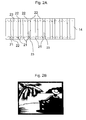
- Figure 2A shows a cross-sectional view of an example of a holographic layer 14.
- the holographic layer 14 may comprise a volume hologram, in which an image, a symbol or data is recorded by means of regions having different refractive indices.
- a volume or Lippmann type hologram may be manufactured by a content production step in which first an image to be shown in the hologram is formed by, for example, capturing images, converting the image into computer graphic images and editing the obtained images. Thereafter, a hologram master is produced so that a plurality of holograms may be manufactured by a simple copying step.
- interference fringes of object illumination light of an image and reference light are successively recorded in a holographic layer using production laser light.
- a wavelength of 100 to 1000 nm, specifically 200 to 900 nm and more specifically 300 to 800 nm and further 400 to 700 nm may be used as production laser light.
- a further holographic layer is brought into contact with the master and copying laser light is irradiated thereto.
- the copying laser light can be identical with the production laser light or of a different spectrum.
- the laser light reflected by the hologram and the (reference) laser light interfere with each other to form interference fringes in the holographic layer.
- the holographic layer is a photosensitive material, in which due to irradiation with electromagnetic radiation a modulation of the refractive index takes place. Examples of photosensitive material are given in US 7,824,822 , US 7,521,155 , US 5,702,846 , and US 5,453,340 .
- the holographic layer may comprise a photosensitive composition such as (a) one or more free-radically polymerizable compounds, (b) one or more free-radical polymerization initiators, (c) one or more cationically polymerizable compounds other than (a), (d) one or more initiators for cationic polymerization and (e) optionally further components.
- a photosensitive composition such as (a) one or more free-radically polymerizable compounds, (b) one or more free-radical polymerization initiators, (c) one or more cationically polymerizable compounds other than (a), (d) one or more initiators for cationic polymerization and (e) optionally further components.
- Suitable free-radically polymerizable compounds (a) are acrylic-based monomers, styrene-based monomers and/or vinyl-based monomers. Specific monomers are acrylamide, methacrylamide, phenyl acrylate, 2 phenoxyethyl acrylate, mono(acryloyloxyethyl) naphthalenedicarboxylate, methylphenoxyethyl acrylate, nonylphenoxyethyl acrylate, acryloyloxyethyl hydrogenphthalate, phenoxy polyethylene glycol acrylate, 2,4,6 tribromophenyl acrylate, mono(2-methacryloyloxyethyl) diphenate, benzyl acrylate, 2,3-dibromophenyl acrylate, 2 hydroxy-3 phenoxypropyl acrylate, 2 naphthyl acrylate, N vinylcarbazole, 2 (9 carbazolyl)ethyl acrylate, triphenylmethyl triacryl
- the initiators used for a free-radical polymerization (b) may be any desired free-radical-generating substances, for instance organic dyes with polymer salts, for example cyanines or salts of diphenyl-iodonium and diaryliodonium.
- anhydro-3,3'-dicarboxymethyl-9-ethyl-2,2'-thiacarbo-cyanine betaine anhydro-3-carboxymethyl-3',9-diethyl-2,2'-thiacarbocyanine betaine, 3,3',9-triethyl-2,2'-thiacarbocyanine iodide, 3,9-diethyl-3'-carboxymethyl-2,2'-thiacarbocyanine iodide and 3,3',9-triethyl-2,2'-(4,5,4',5',-dibenzo)thiacarbocyanine iodide, 2-[3-(3-ethyl-2-benzothiazolidene)-1-propenyl]-6-[2-(3-(3-ethyl-2-benzothiazolidene)ethylideneimino]-3-ethyl-1,3,5-thiadiazolium i
- iodonium salts for example halides, tetra-fluoro-borates or hexafluorophosphates, are diphenyliodonium, 4,4'-dichlorodiphenyliodonium, (4-methoxyphenyl)phenyl-iodonium, (4-octyloxyphenyl)phenyliodonium, 4,4'-dimethoxydiphenyliodonium, 4,4'-di-tert-butyldiphenyl-iodonium and 3,3'-dinitrodiphenyliodonium salts. It will be appreciated that it is also possible to use mixtures of a plurality of the compounds mentioned.
- Component (c) of the photosensitive composition is one or more cationically polymerizable compounds.
- examples are glycidyl-based compounds, epoxides or vinyl-based compounds.
- Specific monomers are diglycerol polyglycidyl ether, pentaerythritol polyglycidyl ether, 1,4-bis(2,3-epoxypropoxyperfluoroisopropyl)cyclohexane, sorbitol polyglycidyl ether, trimethylolpropane poly-glycidyl ether, resorcinol diglycidyl ether, 1,6-hexanediol diglycidyl ether, polyethylene glycol diglycidyl ether, phenyl glycidyl ether, p-t-butyl-phenyl diglycidyl ether, diglycidyl adipate, diglycidyl o-phthalate, dibromophenyl
- Component (d) of the photosensitive composition is an initiator for a cationic polymerization.
- Suitable compounds here are those which, after decomposition, generate Br ⁇ nsted or Lewis acids, for example diaryl-iodonium salts, triarylsulphonium salts, iron-allene salts and the like.
- diaryliodonium salts are tetrafluoroborates, hexafluorophosphates, hexa-fluoroarsenates and hexafluoroantimonates of iodonium compounds.
- triarylsulphonium salts are tetrafluoroborates, hexafluorophosphates, hexafluoro-arsenates and hexafluoroantimonates of sulphonium or triphenylsulphonium compounds, for instance 4-tert-butyltriphenylsulphonium, tris(4-methylphenyl)sulphonium, tris(4-methoxyphenyl)sulphonium, 4-thiophenyltriphenyl-sulphonium. Combinations of a plurality of the compounds mentioned are also suitable.
- the photosensitive composition may optionally comprise organic solvents, for example ketones, esters, ethers, dioxanes, hydrocarbons, for instance cyclohexane, halo-hydrocarbons, aromatics, alcohols or mixtures of one or more such solvents. It is also possible to use solvent-free photopolymer compositions. Further possible additives are binders, thermal polymerization inhibitors, silane coupling agents, plasticizers, dyes and/or copolymers. Further examples comprise lithium niobate, barium titanate, and gallium arsenide. Typical layer thicknesses of holographic material are 10nm to 1mm, specifically 100nm to 100 ⁇ m, more specifically 1 ⁇ m to 50 ⁇ m.
- a holographic layer may comprise a photopolymer in which upon irradiation with light, monomer particles are polymerized in the exposed portion. As the monomer particles are further polymerized, they move to the exposed portion. Thereby, the concentration of monomer particles varies by location. As a result, refractive index modulation occurs. Thereafter, when ultraviolet light or visible light is irradiated on the entire surface of the photopolymer, the monomer particles are completely polymerized. Thereby, a kind of "fixation step" takes place. Since the refractive index of the optical cured photopolymer varies with incident light, interference fringes (brightness and darkness) that occurred due to interference between reference and object illumination light can be recorded as changes of refractive index.
- Figure 2A shows an example of a correspondingly manufactured holographic layer 14.
- portions 21 having a first refractive index are disposed alternately to regions 22 having a second refractive index.
- Refractive indices are typically in the range of 1,48 to 1,53 where the index modulation is typically 0,03 to 0,04.
- the hologram comprises a luminescent material.
- the luminescent material 23 is configured to absorb light having a specific wavelength.
- the luminescent material 23 can be configured to absorb light having a wavelength that has been used for producing the hologram.
- the wavelength that has been used for producing the hologram determines the minimal structural feature size of the hologram.
- the minimal structural feature size theoretically may be equal to a fraction of the wavelength, the fraction depending on the geometry used for forming the hologram. Since, as will be explained in the following, the copying conditions are identical or close to the producing conditions of the hologram, the structures will be identically reproduced. Accordingly, there is a relationship between the wavelength that is absorbed by the luminescent material and the minimal structural feature size of the hologram.
- the luminescent material further is configured to emit light having a second wavelength or more wavelengths.
- the second wavelength may be identical with the first wavelength.
- the luminescent material 23 may also emit light having a wavelength that is different from the first wavelength.
- the luminescent material 23 may be incorporated in the holographic layer 14.
- the luminescent material 23 may extend to such a depth of the holographic layer 14 that the hologram will be destroyed if it is tried to remove the luminescent material 23.
- the luminescent material may as well be disposed in a layer that is different from the holographic layer 14.
- the luminescent material may be incorporated in any of the other layers 11, 12, 13, 15, 16, and 18. Examples for the luminescent material may comprise the following:
- the compound may comprise at least one further element selected from the group consisting of yttrium, lanthanum, cerium, praseodymium, neodymium, samarium, europium, gadolinium, terbium, dysprosium, holmium, erbium, thulium, ytterbium, and lutetium.
- the compound may further comprise at least one dopant selected from oxides and/or fluorides of main group or transition group elements.
- the second wavelength may be different from the first wavelength. Accordingly, so-called stokes or anti-stokes luminescent substances comprising lanthanoid compounds may be used. Examples thereof are described in WO 00/60527 , WO 2008/000461 , US 6,802,992 and US 6,686,074 .
- Figure 2B shows a plan view of an example of a hologram showing a specific pattern which is made from regions having different refractive indices. For example, upon viewing the hologram using normal lighting conditions, the luminescent material will not be recognized from the image.
- Figure 3 shows an example of a manufacturing process of a hologram.
- a hologram master 33 is placed over a holographic layer 31 that may comprise a photopolymer as described above.
- the holographic layer 31 may have a thickness of 10 to 20 ⁇ m.
- the photopolymer layer may be coated on a suitable carrier.
- laser light having a specific wavelength is irradiated on the master 33 so that the pattern of the master layer is copied onto the holographic layer 31.
- laser light is reflected by the hologram recorded in the master.
- the reflected laser light and the laser light (reference light) interfere with each other to form interference fringes.
- the interference fringes are recorded as changes of the refractive index of the photopolymer.
- a laser emitting a wavelength in the range of 400 to 700 nm having a sharp wavelength distribution and a high power may be used for copying the pattern.
- the master 33 may be moved over the holographic layer 31 so as to obtain a plurality of successively copied portions.
- a developing step is performed so as to polymerize the remaining portions of the polymer. For example, this may be accomplished by irradiating ultraviolet rays to fully cure the ultraviolet ray curing resin. Nevertheless, depending on the properties of the photopolymer layer, any other curing method may be used.
- the luminescent material 23 may be introduced in the holographic layer 31.
- the luminescent material 23 may be introduced in the holographic layer 31 by means of a thermo transfer or thermo re-transfer method.
- the photo luminescent material may be disposed on a thermo transfer sheet 32.
- the thermo transfer sheet 32 is disposed in contact with the holographic layer 31, and heat is applied to the layer stack while simultaneously applying pressure to the layer stack so that the photo luminescent material may be incorporated into the holographic layer 31.
- the photo luminescent material 32 may be included in the holographic layer 31 as is also illustrated in Figure 2A .
- erbium doped CaS which is luminescent at 532 nm has been taken as an example of the photo luminescent material.
- further examples of the photo luminescent material may comprise the following:
- the luminescent material is incorporated before or after the step of developing the photopolymer. Accordingly, the photoluminescent material is disposed adjacent to one or both of the surfaces of the holographic layer. Thereafter, the holographic layer is further processed by applying the further layers by generally known processes. Then, the sheet-like layer stack will be cut into pieces to isolate the single holographic labels.
- Figure 4 illustrates a method of forming a hologram.
- the method may comprise exposing portions of a photo sensitive layer to a light source having at least a first wavelength (S1), selecting a luminescent material (S2), the luminescent material being configured to absorb the first wavelength and to emit light having a second wavelength and incorporating the luminescent material into the hologram.
- S1 first wavelength
- S2 luminescent material
- a hologram may be faked by copying the hologram onto a further holographic layer. Due to the incorporation of the luminescent material in the hologram, for example in the holographic layer or in any other layer of the holographic layer stack, upon irradiation with the copying laser light, the luminescent material will be excited and becomes luminescent under the copying laser light. As a result, the holographic image will be outshined or blurred so that an image transfer may be made impossible. Consequently, unauthorized copying or faking of a holographic label will be prevented. Therefore, due to the incorporation of the luminescent material into the hologram, the security level of the hologram can be increased significantly.
- the hologram may be manufactured utilizing more than one wavelength of the irradiating laser light.
- This kind of holograms sometimes is referred to RGB holograms (in the case of three manufacturing wavelengths) or rainbow holograms (in the case of a plurality of manufacturing wavelengths).
- a plurality of luminescent materials each absorbing a specific wavelength of the manufacturing wavelengths may be selected and incorporated into the hologram, for example, the holographic layer or any other layer of the hologram layer stack.
- a luminescent material absorbing a plurality of manufacturing wavelengths can be selected and incorporated into the hologram.
- Fig. 5 shows a mobile phone 40 as an example of a device comprising a hologram 41 as described above.
- the device may comprise a computer, portable electronic equipment such as a mobile phone, a personal digital assistant, an MP3 player, a watch, a camera, a notebook and others.
- the device may also comprise electronic accessories such as a memory card or a battery.
- the mobile phone 40 may further comprise the usual components such as a display 42 and a keypad 43.
- the mobile phone is only given by way of example. It is clearly to be understood, that the device may be embodied by various other electronic equipment as has been mentioned above.
- the hologram may be attached or adhered to the device.
- the hologram 41 may be adhered to the device 40 so that it cannot be removed without destroying the hologram 41.
- Fig. 6 shows a package 50 comprising a hologram 51 as described above.
- the package 50 may be a package of an electronic device or equipment.
- the package may be a package of a brand product such as a specific medicine or arbitrary consumer products as exemplified by coffee, chocolate, cigarettes and others.
- the shape of the package 50 is given as an example. As is clearly to be understood, the shape of the package 50 may be arbitrary, depending on the products packaged by the package.
- the package 50 may also comprise a blister for packaging tablets or pills.
Landscapes
- Engineering & Computer Science (AREA)
- Computer Security & Cryptography (AREA)
- Physics & Mathematics (AREA)
- General Physics & Mathematics (AREA)
- Holo Graphy (AREA)
- Credit Cards Or The Like (AREA)
- Diffracting Gratings Or Hologram Optical Elements (AREA)
Abstract
A hologram comprises a holographic layer comprising a photosensitive layer, holographic structures being formed in the holographic layer using a light source having at least a first wavelength, and a luminescent material, the luminescent material being configured to absorb the first wavelength, and to emit light having a second wavelength.
A method of forming a hologram comprises exposing portions of a photosensitive layer to a light source having at least a first wavelength to form holographic structures in the photosensitive layer, selecting a luminescent material, the luminescent material being configured to absorb the first wavelength, and to emit light having a second wavelength, and incorporating the luminescent material into the hologram.
Description
- The present application relates to a hologram as well as to a method of forming a hologram.
- Holograms have become widely used to determine whether or not sovereign documents such as banknotes, passports, ID cards and other personalized documents as well as credit cards are genuine or fake. Further, holograms are used to secure brand products from counterfeit. Examples for holograms comprise emboss type holograms in which an interference film is unevenly formed as is, for example, described in
US 2002/0191234 . Further examples comprise volume type holograms, in which the refractive index of an interference film is spatially modulated. In order to improve security, it is an important issue to protect the holograms themselves from making copies thereof. - It is an object of the present invention to provide an improved hologram as well as a method of forming a hologram having improved properties.
- According to the present invention, the above objects are solved by the claimed matter according to the independent claims.
- The accompanying drawings are included to provide a further understanding of embodiments of the invention and are incorporated in and constitute a part of this specification. The drawings illustrate the embodiments of the present invention and together with the description serve to explain the principles. Other embodiments of the invention and many of the intended advantages will be readily appreciated, as they become better understood by reference to the following detailed description. The elements of the drawings are not necessarily to scale relative to each other. Like reference numbers designate corresponding similar parts.
-
Figure 1 shows a schematic cross-sectional view of a layer stack including a hologram. -
Figure 2A shows a schematic cross-sectional view of a holographic layer. -
Figure 2B shows a plan view of an example of a hologram. -
Figure 3 illustrates an example of a method of forming a hologram. -
Figure 4 is a flow diagram of a method of forming a hologram. -
Figure 5 shows an embodiment of a device comprising a hologram. -
Figure 6 shows an embodiment of a package comprising a hologram. - In the following detailed description reference is made to the accompanying drawings, which form a part hereof and in which are illustrated by way of illustration specific embodiments in which the invention may be practiced. In this regard, directional terminology such as "top", "bottom", "front", "back", "leading", "trailing" etc. is used with reference to the orientation of the Figures being described. Since components of embodiments of the invention can be positioned in a number of different orientations, the directional terminology is used for purposes of illustration and is in no way limiting. It is to be understood that other embodiments may be utilized and structural or logical changes may be made without departing from the scope defined by the claims.
-
Figure 1 illustrates an example of a layer stack that may form a holographic label. The holographic label may be attached or integrated into asubstrate 10. For example, thesubstrate 10 may be a brand product or a security document or any other item that is to be identified or labelled. The holographic label may be attached or integrated to the substrate. The label comprises anadhesive layer 11 that may be made of a suitable adhesive that is generally known or may be specifically developed. Over theadhesive layer 11, ablack film 12 may be disposed. For example, this black film may be made of a common material such as rubber type adhesive film. The black film may be useful if the holographic label is to be used as a reflection hologram to increase contrast between the holographic image and the black background. As is to be clearly understood, theblack film 12 may as well be omitted. Aholographic layer 14 is attached to theblack film 12 by means of a furtheradhesive layer 13. During the formation of the holographic layer anintermediate film 16 may be used made of a common material such as polyester (PET) film which is coated with the holographic material such as a photosensitive composition as described inUS 5,453,340 . Theholographic layer 14 can be attached to theintermediate film 16 by means of a furtheradhesive layer 15 or may be coated on theintermediate film 16 which may omit theadhesive layer 15. Acover film 18 that may be used for protecting the hologram against environmental influences may be formed over theintermediate film 16. As is to be clearly understood, the layer stack may comprise further layers. A typical layer stack for a hologram would be adhesive layer11, followed byblack film 12, followed byadhesive layer 13,holographic layer 14,intermediate film 16 andcover film 18. - The holographic layer may comprise a volume hologram, for example a transmission or a reflection hologram. Specific types of holograms are Lippmann holograms, Denisjuk holograms, RGB holograms, rainbow hologram, computer-generated or digital holograms.
-
Figure 2A shows a cross-sectional view of an example of aholographic layer 14. Theholographic layer 14 may comprise a volume hologram, in which an image, a symbol or data is recorded by means of regions having different refractive indices. - For example, generally a volume or Lippmann type hologram may be manufactured by a content production step in which first an image to be shown in the hologram is formed by, for example, capturing images, converting the image into computer graphic images and editing the obtained images. Thereafter, a hologram master is produced so that a plurality of holograms may be manufactured by a simple copying step. For manufacturing a hologram master, interference fringes of object illumination light of an image and reference light are successively recorded in a holographic layer using production laser light. For example, a wavelength of 100 to 1000 nm, specifically 200 to 900 nm and more specifically 300 to 800 nm and further 400 to 700 nm may be used as production laser light. For copying the master, a further holographic layer is brought into contact with the master and copying laser light is irradiated thereto. The copying laser light can be identical with the production laser light or of a different spectrum. The laser light reflected by the hologram and the (reference) laser light interfere with each other to form interference fringes in the holographic layer. Thereby, the hologram is copied. The holographic layer is a photosensitive material, in which due to irradiation with electromagnetic radiation a modulation of the refractive index takes place. Examples of photosensitive material are given in
US 7,824,822 ,US 7,521,155 ,US 5,702,846 , andUS 5,453,340 . The holographic layer may comprise a photosensitive composition such as (a) one or more free-radically polymerizable compounds, (b) one or more free-radical polymerization initiators, (c) one or more cationically polymerizable compounds other than (a), (d) one or more initiators for cationic polymerization and (e) optionally further components. - Examples of suitable free-radically polymerizable compounds (a) are acrylic-based monomers, styrene-based monomers and/or vinyl-based monomers. Specific monomers are acrylamide, methacrylamide, phenyl acrylate, 2 phenoxyethyl acrylate, mono(acryloyloxyethyl) naphthalenedicarboxylate, methylphenoxyethyl acrylate, nonylphenoxyethyl acrylate, acryloyloxyethyl hydrogenphthalate, phenoxy polyethylene glycol acrylate, 2,4,6 tribromophenyl acrylate, mono(2-methacryloyloxyethyl) diphenate, benzyl acrylate, 2,3-dibromophenyl acrylate, 2 hydroxy-3 phenoxypropyl acrylate, 2 naphthyl acrylate, N vinylcarbazole, 2 (9 carbazolyl)ethyl acrylate, triphenylmethyl triacrylate, 2-(tricyclo[5.2.1.02,6]dibromodecylthio)-ethyl acrylate, S (1 naphthylmethyl) thioacrylate, dicyclopentanyl acrylate, methylenebisacrylamide, polyethylene glycol diacrylate, trimethylpropane triacrylate, pentaerythritol acrylate, 2 acryloyloxy-ethyl 3-acryloyloxypropyl 2-hydroxydiphenate, 2 acryloyloxyethyl 3-acryloyloxypropyl 2-hydroxy-2,3-naphthalenedicarboxylate, 2-acryloyloxyethyl 3 acryloyloxypropyl 2-hydroxy-4,5-phenanthrenedi-carboxylate, dibromoneopentyl glycol diacrylate, dipentaerythritol hexaacrylate, 1,3-bis[2-acryloyloxy-3-(2,4,6-tribromophenoxy)propoxy]benzene, diethylene dithioglycol diacrylate, 2,2-bis(4-acryloyloxyethoxy-phenyl)propane, bis(4-acryloyloxydiethoxyphenyl)-methane, bis(4-acryloyloxyethoxy-3,5-dibromophenyl)-methane, 2,2-bis(4-acryoyloxyethoxyphenyl)propane, 2,2-bis(4-acryloyloxyethoxy-3,5-dibromophenyl)propane, bis(4-acryoyloxyethoxyphenyl) sulphone, bis(4-acryloyl-oxydiethoxyphenyl) sulphone, bis(4-acryloyloxypropoxy-phenyl) sulphone, bis(4-acryoyloxyethoxy-3,5-dibromo-phenyl) sulphone, styrene and 2-bromostyrene. It will be appreciated that it is also possible to use mixtures of a plurality of the compounds mentioned.
- The initiators used for a free-radical polymerization (b) may be any desired free-radical-generating substances, for instance organic dyes with polymer salts, for example cyanines or salts of diphenyl-iodonium and diaryliodonium. Specific examples are anhydro-3,3'-dicarboxymethyl-9-ethyl-2,2'-thiacarbo-cyanine betaine, anhydro-3-carboxymethyl-3',9-diethyl-2,2'-thiacarbocyanine betaine, 3,3',9-triethyl-2,2'-thiacarbocyanine iodide, 3,9-diethyl-3'-carboxymethyl-2,2'-thiacarbocyanine iodide and 3,3',9-triethyl-2,2'-(4,5,4',5',-dibenzo)thiacarbocyanine iodide, 2-[3-(3-ethyl-2-benzothiazolidene)-1-propenyl]-6-[2-(3-(3-ethyl-2-benzothiazolidene)ethylideneimino]-3-ethyl-1,3,5-thiadiazolium iodide, 2-[[3-allyl-4-oxo-5-(3-n propyl-5,6-dimethyl-2-benzothiazolidene)ethylidene-thiazolidene]methyl]3-ethyl-4,5-diphenylthiazolinium iodide, 1,1',3,3,3',3'-hexamethyl-2,2'-indo¬tri¬carbo¬cyanine iodide, 3,3'-diethyl-2,2'-thiatricarbocyanine perchlorate, anhydro-1-ethyl-4-methoxy-3'-carboxymethyl-5'-chloro-2,2'-quinothiacyanine betaine, anhydro-5,5'-diphenyl-9-ethyl-3,3'-disulphopropyloxa-carbocyanine hydroxide triethylamine salt. Specific examples of iodonium salts, for example halides, tetra-fluoro-borates or hexafluorophosphates, are diphenyliodonium, 4,4'-dichlorodiphenyliodonium, (4-methoxyphenyl)phenyl-iodonium, (4-octyloxyphenyl)phenyliodonium, 4,4'-dimethoxydiphenyliodonium, 4,4'-di-tert-butyldiphenyl-iodonium and 3,3'-dinitrodiphenyliodonium salts. It will be appreciated that it is also possible to use mixtures of a plurality of the compounds mentioned.
- Component (c) of the photosensitive composition is one or more cationically polymerizable compounds. Examples are glycidyl-based compounds, epoxides or vinyl-based compounds. Specific monomers are diglycerol polyglycidyl ether, pentaerythritol polyglycidyl ether, 1,4-bis(2,3-epoxypropoxyperfluoroisopropyl)cyclohexane, sorbitol polyglycidyl ether, trimethylolpropane poly-glycidyl ether, resorcinol diglycidyl ether, 1,6-hexanediol diglycidyl ether, polyethylene glycol diglycidyl ether, phenyl glycidyl ether, p-t-butyl-phenyl diglycidyl ether, diglycidyl adipate, diglycidyl o-phthalate, dibromophenyl glycidyl ether, dibromo-neopentyl glycol, glycol diglycidyl ether, 1,6-di-methylolperfluorohexane glycidyl ether, 1,2,7,8-di-epoxyoctane, 4,4'-bis(2,3-epoxypropoxyperfluoro-iso-propyl)diphenyl ether, 3,4-epoxycyclohexylmethyl 3',4'-epoxycyclohexanecarboxylate, 3,4-epoxycyclohexyl-oxirane, 1,2,5,6-diepoxy-4,7-methaneperhydroindene, 2-(3,4-epoxycyclohexyl)-3',4'-epoxy-1,3-dioxane-5-spiro-cyclohexane, 1,2 ethylenedioxybis(3,4-epoxycyclohexyl-methane), 4',5'-epoxy-2'-methylcyclohexylmethyl 4,5-epoxy-2-methylcyclohexanecarboxylate, ethylene glycol bis(3,4-epoxycyclohexanecarboxylate), bis(3,4-epoxy-cyclohexylmethyl) adipate, di-2,3-epoxycyclopentyl ether, vinyl 2-chloroethyl ether, vinyl n-butyl ether, triethylene glycol divinyl ether, 1,4-cyclohexane-dimethanol divinyl ether, trimethylolethane trivinyl ether or vinyl glycidyl ether. It is also possible to use combinations of the abovementioned compounds.
- Component (d) of the photosensitive composition is an initiator for a cationic polymerization. Suitable compounds here are those which, after decomposition, generate Brønsted or Lewis acids, for example diaryl-iodonium salts, triarylsulphonium salts, iron-allene salts and the like. Examples of diaryliodonium salts are tetrafluoroborates, hexafluorophosphates, hexa-fluoroarsenates and hexafluoroantimonates of iodonium compounds. Examples of triarylsulphonium salts are tetrafluoroborates, hexafluorophosphates, hexafluoro-arsenates and hexafluoroantimonates of sulphonium or triphenylsulphonium compounds, for instance 4-tert-butyltriphenylsulphonium, tris(4-methylphenyl)sulphonium, tris(4-methoxyphenyl)sulphonium, 4-thiophenyltriphenyl-sulphonium. Combinations of a plurality of the compounds mentioned are also suitable.
- The photosensitive composition may optionally comprise organic solvents, for example ketones, esters, ethers, dioxanes, hydrocarbons, for instance cyclohexane, halo-hydrocarbons, aromatics, alcohols or mixtures of one or more such solvents. It is also possible to use solvent-free photopolymer compositions. Further possible additives are binders, thermal polymerization inhibitors, silane coupling agents, plasticizers, dyes and/or copolymers. Further examples comprise lithium niobate, barium titanate, and gallium arsenide. Typical layer thicknesses of holographic material are 10nm to 1mm, specifically 100nm to 100µm, more specifically 1µm to 50µm. For example, a holographic layer may comprise a photopolymer in which upon irradiation with light, monomer particles are polymerized in the exposed portion. As the monomer particles are further polymerized, they move to the exposed portion. Thereby, the concentration of monomer particles varies by location. As a result, refractive index modulation occurs. Thereafter, when ultraviolet light or visible light is irradiated on the entire surface of the photopolymer, the monomer particles are completely polymerized. Thereby, a kind of "fixation step" takes place. Since the refractive index of the optical cured photopolymer varies with incident light, interference fringes (brightness and darkness) that occurred due to interference between reference and object illumination light can be recorded as changes of refractive index.
-
Figure 2A shows an example of a correspondingly manufacturedholographic layer 14. As can be seen from the cross-section,portions 21 having a first refractive index are disposed alternately toregions 22 having a second refractive index. Refractive indices are typically in the range of 1,48 to 1,53 where the index modulation is typically 0,03 to 0,04. Furthermore, the hologram comprises a luminescent material. Theluminescent material 23 is configured to absorb light having a specific wavelength. In particular, theluminescent material 23 can be configured to absorb light having a wavelength that has been used for producing the hologram. Generally, the wavelength that has been used for producing the hologram determines the minimal structural feature size of the hologram. For example, the minimal structural feature size theoretically may be equal to a fraction of the wavelength, the fraction depending on the geometry used for forming the hologram. Since, as will be explained in the following, the copying conditions are identical or close to the producing conditions of the hologram, the structures will be identically reproduced. Accordingly, there is a relationship between the wavelength that is absorbed by the luminescent material and the minimal structural feature size of the hologram. The luminescent material further is configured to emit light having a second wavelength or more wavelengths. For example, the second wavelength may be identical with the first wavelength. Nevertheless, as will be explained also in the following, theluminescent material 23 may also emit light having a wavelength that is different from the first wavelength. As is shown inFigure 2A , theluminescent material 23 may be incorporated in theholographic layer 14. For example, theluminescent material 23 may extend to such a depth of theholographic layer 14 that the hologram will be destroyed if it is tried to remove theluminescent material 23. Nevertheless, as is to be clearly understood, the luminescent material may as well be disposed in a layer that is different from theholographic layer 14. For example, the luminescent material may be incorporated in any of theother layers - A compound which may comprise an oxide, oxide sulphate or oxide fluoride of an alkali, earth alkali or transition element, lanthanide oxide, lanthanide oxide sulphate or lanthanide oxide fluoride. Optionally, the compound may comprise at least one further element selected from the group consisting of yttrium, lanthanum, cerium, praseodymium, neodymium, samarium, europium, gadolinium, terbium, dysprosium, holmium, erbium, thulium, ytterbium, and lutetium. Optionally, the compound may further comprise at least one dopant selected from oxides and/or fluorides of main group or transition group elements. As has been mentioned above, the second wavelength may be different from the first wavelength. Accordingly, so-called stokes or anti-stokes luminescent substances comprising lanthanoid compounds may be used. Examples thereof are described in
WO 00/60527 WO 2008/000461 ,US 6,802,992 andUS 6,686,074 . -
Figure 2B shows a plan view of an example of a hologram showing a specific pattern which is made from regions having different refractive indices. For example, upon viewing the hologram using normal lighting conditions, the luminescent material will not be recognized from the image. -
Figure 3 shows an example of a manufacturing process of a hologram. Ahologram master 33 is placed over aholographic layer 31 that may comprise a photopolymer as described above. For example, theholographic layer 31 may have a thickness of 10 to 20 µm. The photopolymer layer may be coated on a suitable carrier. Then, laser light having a specific wavelength is irradiated on themaster 33 so that the pattern of the master layer is copied onto theholographic layer 31. To be more specific, laser light is reflected by the hologram recorded in the master. The reflected laser light and the laser light (reference light) interfere with each other to form interference fringes. The interference fringes are recorded as changes of the refractive index of the photopolymer. For example, a laser emitting a wavelength in the range of 400 to 700 nm having a sharp wavelength distribution and a high power may be used for copying the pattern. For example, themaster 33 may be moved over theholographic layer 31 so as to obtain a plurality of successively copied portions. Then, a developing step is performed so as to polymerize the remaining portions of the polymer. For example, this may be accomplished by irradiating ultraviolet rays to fully cure the ultraviolet ray curing resin. Nevertheless, depending on the properties of the photopolymer layer, any other curing method may be used. Thereafter, theluminescent material 23 may be introduced in theholographic layer 31. For example, theluminescent material 23 may be introduced in theholographic layer 31 by means of a thermo transfer or thermo re-transfer method. For example, the photo luminescent material may be disposed on athermo transfer sheet 32. Thethermo transfer sheet 32 is disposed in contact with theholographic layer 31, and heat is applied to the layer stack while simultaneously applying pressure to the layer stack so that the photo luminescent material may be incorporated into theholographic layer 31. As a result, thephoto luminescent material 32 may be included in theholographic layer 31 as is also illustrated inFigure 2A . In the present example, erbium doped CaS which is luminescent at 532 nm has been taken as an example of the photo luminescent material. Nevertheless, further examples of the photo luminescent material may comprise the following: - Zn2SiO4:Mn,As
- Gd2O2S:Tb
- Y2O2S:Tb
- Y3Al5O12:Ce
- Y3Al5O12:Tb
- ZnS:Cu,Al
- ZnS:Cu,Au,Al
- Y2SiO5:Tb
- Y2OS:Tb
- Y3(Al,Ga)5O12:Ce
- Y3(Al,Ga)5O12:Tb
- InBO3:Tb
- (Ce,Tb)MgAl11O19
- BaMg2Al16O27:Eu(II),Mn(II)
- Ce0.67Tb0.33MgAl11O19:Ce,Tb
- Zn2SiO4:Mn,Sb2O3
- LaPO4:Ce,Tb
- (La,Ce,Tb)PO4:Ce,Tb
- The luminescent material is incorporated before or after the step of developing the photopolymer. Accordingly, the photoluminescent material is disposed adjacent to one or both of the surfaces of the holographic layer. Thereafter, the holographic layer is further processed by applying the further layers by generally known processes. Then, the sheet-like layer stack will be cut into pieces to isolate the single holographic labels.
-
Figure 4 illustrates a method of forming a hologram. As is shown inFigure 4 , the method may comprise exposing portions of a photo sensitive layer to a light source having at least a first wavelength (S1), selecting a luminescent material (S2), the luminescent material being configured to absorb the first wavelength and to emit light having a second wavelength and incorporating the luminescent material into the hologram. - As has become apparent from
Figure 3 , conventionally, a hologram may be faked by copying the hologram onto a further holographic layer. Due to the incorporation of the luminescent material in the hologram, for example in the holographic layer or in any other layer of the holographic layer stack, upon irradiation with the copying laser light, the luminescent material will be excited and becomes luminescent under the copying laser light. As a result, the holographic image will be outshined or blurred so that an image transfer may be made impossible. Consequently, unauthorized copying or faking of a holographic label will be prevented. Therefore, due to the incorporation of the luminescent material into the hologram, the security level of the hologram can be increased significantly. - According to a further modification, the hologram may be manufactured utilizing more than one wavelength of the irradiating laser light. This kind of holograms sometimes is referred to RGB holograms (in the case of three manufacturing wavelengths) or rainbow holograms (in the case of a plurality of manufacturing wavelengths). In this case, a plurality of luminescent materials, each absorbing a specific wavelength of the manufacturing wavelengths may be selected and incorporated into the hologram, for example, the holographic layer or any other layer of the hologram layer stack. As a further option, a luminescent material absorbing a plurality of manufacturing wavelengths can be selected and incorporated into the hologram.
-
Fig. 5 shows amobile phone 40 as an example of a device comprising ahologram 41 as described above. For example, the device may comprise a computer, portable electronic equipment such as a mobile phone, a personal digital assistant, an MP3 player, a watch, a camera, a notebook and others. The device may also comprise electronic accessories such as a memory card or a battery. Themobile phone 40 may further comprise the usual components such as adisplay 42 and akeypad 43. The mobile phone is only given by way of example. It is clearly to be understood, that the device may be embodied by various other electronic equipment as has been mentioned above. The hologram may be attached or adhered to the device. For example, thehologram 41 may be adhered to thedevice 40 so that it cannot be removed without destroying thehologram 41. -
Fig. 6 shows apackage 50 comprising ahologram 51 as described above. For example, thepackage 50 may be a package of an electronic device or equipment. Alternatively, the package may be a package of a brand product such as a specific medicine or arbitrary consumer products as exemplified by coffee, chocolate, cigarettes and others. The shape of thepackage 50 is given as an example. As is clearly to be understood, the shape of thepackage 50 may be arbitrary, depending on the products packaged by the package. Thepackage 50 may also comprise a blister for packaging tablets or pills. - While embodiments of the invention have been described above, it is obvious that further embodiments may be implemented. For example, further embodiments may comprise any subcombination of features recited in the claims or any subcombination of elements described in the examples given above. Accordingly, this spirit and scope of the appended claims should not be limited to the description of the embodiments contained herein.
Claims (15)
- A hologram comprising:a holographic layer comprising a photosensitive layer, holographic structures being formed in the holographic layer using a light source having at least a first wavelength, anda luminescent material, the luminescent material being configured to absorb the first wavelength, and to emit light having a second wavelength.
- The hologram according to claim 1,
wherein the first wavelength is equal to the second wavelength. - The hologram according to claim 1,
wherein the luminescent material is included in the holographic layer. - The hologram according to claim 1,
wherein the holographic structures comprise regions having mutually different refractive indices. - The hologram according to claim 1,
further comprising additional holographic structures being formed in the holographic layer using a light source having at least a third wavelength, and
an additional luminescent material, the additional luminescent material being configured to absorb the third wavelength and to emit light having a fourth wavelength. - The hologram according to claim 1,
further comprising additional holographic structures being formed in the holographic layer using a light source having at least a third wavelength, wherein the luminescent material further is configured to absorb the third wavelength and to emit light having a fourth wavelength. - A method of forming a hologram, comprising:exposing portions of a photosensitive layer to a light source having at least a first wavelength to form holographic structures in the photosensitive layer;selecting a luminescent material, the luminescent material being configured to absorb the first wavelength, and to emit light having a second wavelength, andincorporating the luminescent material into the hologram.
- The method according to claim 7,
the method further comprising developing the exposed photosensitive layer,
wherein the luminescent material is incorporated into the photosensitive layer after developing the exposed photosensitive layer. - The method according to claim 8,
wherein the luminescent material is incorporated into the photosensitive layer by a thermotransfer method. - The method according to claim 7,
wherein due to exposing the portions of the photosensitive layer portions having different refractive indices are formed in the photosensitive layer. - The method according to claim 7,
further comprising forming additional holographic structures by exposing the photosensitive layer to an additional light source having at least a third wavelength;
selecting an additional luminescent material, the additional luminescent material being configured to absorb the third wavelength and to emit light having a fourth wavelength, and
incorporating the additional luminescent material into the hologram. - The method according to claim 7,
further comprising forming additional holographic structures by exposing the photosensitive layer to an additional light source having at least a third wavelength, wherein the luminescent material is selected further to absorb the third wavelength and to emit light having a fourth wavelength. - A device comprising the hologram according to any of claims 1 to 6.
- The device according to claim 13, the device being an electric mobile device.
- A package comprising the hologram according to any of claims 1 to 6.
Priority Applications (6)
| Application Number | Priority Date | Filing Date | Title |
|---|---|---|---|
| EP11005309A EP2541343A1 (en) | 2011-06-29 | 2011-06-29 | Hologram and method of forming a hologram |
| TW101121763A TW201314390A (en) | 2011-06-29 | 2012-06-18 | Hologram and method of forming a hologram |
| JP2012137801A JP2013011888A (en) | 2011-06-29 | 2012-06-19 | Hologram and method of forming hologram |
| US13/530,652 US20130003153A1 (en) | 2011-06-29 | 2012-06-22 | Hologram and method of forming a hologram |
| CN201210216906.8A CN102854787A (en) | 2011-06-29 | 2012-06-25 | Hologram and method of forming a hologram |
| RU2012126549/28A RU2012126549A (en) | 2011-06-29 | 2012-06-25 | HOLOGRAM AND HOLOGRAM FORMING METHOD |
Applications Claiming Priority (1)
| Application Number | Priority Date | Filing Date | Title |
|---|---|---|---|
| EP11005309A EP2541343A1 (en) | 2011-06-29 | 2011-06-29 | Hologram and method of forming a hologram |
Publications (1)
| Publication Number | Publication Date |
|---|---|
| EP2541343A1 true EP2541343A1 (en) | 2013-01-02 |
Family
ID=44504401
Family Applications (1)
| Application Number | Title | Priority Date | Filing Date |
|---|---|---|---|
| EP11005309A Withdrawn EP2541343A1 (en) | 2011-06-29 | 2011-06-29 | Hologram and method of forming a hologram |
Country Status (6)
| Country | Link |
|---|---|
| US (1) | US20130003153A1 (en) |
| EP (1) | EP2541343A1 (en) |
| JP (1) | JP2013011888A (en) |
| CN (1) | CN102854787A (en) |
| RU (1) | RU2012126549A (en) |
| TW (1) | TW201314390A (en) |
Cited By (1)
| Publication number | Priority date | Publication date | Assignee | Title |
|---|---|---|---|---|
| GB2622830A (en) * | 2022-09-29 | 2024-04-03 | Suretag Ltd | A token for authenticating a product |
Families Citing this family (4)
| Publication number | Priority date | Publication date | Assignee | Title |
|---|---|---|---|---|
| FR3005068B1 (en) | 2013-04-26 | 2017-05-26 | Arjowiggins Security | SECURITY ELEMENT COMPRISING A HOLOGRAM IN VOLUME. |
| JP6303702B2 (en) * | 2014-03-28 | 2018-04-04 | 大日本印刷株式会社 | Scratch label |
| MX2016013899A (en) * | 2014-04-23 | 2017-02-02 | Innovia Security Pty Ltd | Volume holograms for security documents. |
| US10344567B2 (en) * | 2014-06-23 | 2019-07-09 | Rockwell Automation Asia Pacific Business Center Pte. Ltd. | Systems and methods for cloud-based automatic configuration of remote terminal units |
Citations (10)
| Publication number | Priority date | Publication date | Assignee | Title |
|---|---|---|---|---|
| US5453340A (en) | 1991-04-17 | 1995-09-26 | Nippon Paint Company, Ltd. | Photosensitive composition for volume hologram recording |
| US5702846A (en) | 1994-10-03 | 1997-12-30 | Nippon Paint Co. Ltd. | Photosensitive composition for volume hologram recording |
| WO2000060527A1 (en) | 1999-04-07 | 2000-10-12 | Sicpa Holding S.A. | A method and device for exciting a luminescent material |
| US20020191234A1 (en) | 2001-05-30 | 2002-12-19 | Dai Nippon Printing Co., Ltd. | Hologram laminate and hologram label |
| US6686074B2 (en) | 2001-03-16 | 2004-02-03 | Bundesdruckerei Gmbh | Secured documents identified with anti-stokes fluorescent compositions |
| US6802992B1 (en) | 1997-03-05 | 2004-10-12 | Wieczoreck Juergen | Non-green anti-stokes luminescent substance |
| GB2413302A (en) * | 2003-02-20 | 2005-10-26 | Konica Minolta Photo Imaging | Authentication recording medium and authentication recording medium producing method |
| WO2008000461A2 (en) | 2006-06-27 | 2008-01-03 | Swiss Authentication Gmbh | Luminescent composition |
| US7521155B2 (en) | 2003-06-10 | 2009-04-21 | Dai Nippon Printing Co., Ltd. | Volume hologram layer and volume hologram transfer foil |
| US7824822B2 (en) | 2002-07-12 | 2010-11-02 | Dai Nippon Printing Co., Ltd. | Photosensitive compositions for volume hologram recording, photosensitive medium for volume hologram recording and volume hologram |
Family Cites Families (1)
| Publication number | Priority date | Publication date | Assignee | Title |
|---|---|---|---|---|
| US7846639B2 (en) * | 2006-06-30 | 2010-12-07 | E. I. Du Pont De Nemours And Company | Imaging element having a photoluminescent tag and process of using the imaging element to form a recording element |
-
2011
- 2011-06-29 EP EP11005309A patent/EP2541343A1/en not_active Withdrawn
-
2012
- 2012-06-18 TW TW101121763A patent/TW201314390A/en unknown
- 2012-06-19 JP JP2012137801A patent/JP2013011888A/en active Pending
- 2012-06-22 US US13/530,652 patent/US20130003153A1/en not_active Abandoned
- 2012-06-25 CN CN201210216906.8A patent/CN102854787A/en active Pending
- 2012-06-25 RU RU2012126549/28A patent/RU2012126549A/en not_active Application Discontinuation
Patent Citations (10)
| Publication number | Priority date | Publication date | Assignee | Title |
|---|---|---|---|---|
| US5453340A (en) | 1991-04-17 | 1995-09-26 | Nippon Paint Company, Ltd. | Photosensitive composition for volume hologram recording |
| US5702846A (en) | 1994-10-03 | 1997-12-30 | Nippon Paint Co. Ltd. | Photosensitive composition for volume hologram recording |
| US6802992B1 (en) | 1997-03-05 | 2004-10-12 | Wieczoreck Juergen | Non-green anti-stokes luminescent substance |
| WO2000060527A1 (en) | 1999-04-07 | 2000-10-12 | Sicpa Holding S.A. | A method and device for exciting a luminescent material |
| US6686074B2 (en) | 2001-03-16 | 2004-02-03 | Bundesdruckerei Gmbh | Secured documents identified with anti-stokes fluorescent compositions |
| US20020191234A1 (en) | 2001-05-30 | 2002-12-19 | Dai Nippon Printing Co., Ltd. | Hologram laminate and hologram label |
| US7824822B2 (en) | 2002-07-12 | 2010-11-02 | Dai Nippon Printing Co., Ltd. | Photosensitive compositions for volume hologram recording, photosensitive medium for volume hologram recording and volume hologram |
| GB2413302A (en) * | 2003-02-20 | 2005-10-26 | Konica Minolta Photo Imaging | Authentication recording medium and authentication recording medium producing method |
| US7521155B2 (en) | 2003-06-10 | 2009-04-21 | Dai Nippon Printing Co., Ltd. | Volume hologram layer and volume hologram transfer foil |
| WO2008000461A2 (en) | 2006-06-27 | 2008-01-03 | Swiss Authentication Gmbh | Luminescent composition |
Cited By (1)
| Publication number | Priority date | Publication date | Assignee | Title |
|---|---|---|---|---|
| GB2622830A (en) * | 2022-09-29 | 2024-04-03 | Suretag Ltd | A token for authenticating a product |
Also Published As
| Publication number | Publication date |
|---|---|
| RU2012126549A (en) | 2013-12-27 |
| JP2013011888A (en) | 2013-01-17 |
| US20130003153A1 (en) | 2013-01-03 |
| TW201314390A (en) | 2013-04-01 |
| CN102854787A (en) | 2013-01-02 |
Similar Documents
| Publication | Publication Date | Title |
|---|---|---|
| JP4985137B2 (en) | Volume hologram transfer foil, volume hologram laminate, and manufacturing method thereof | |
| EP2541343A1 (en) | Hologram and method of forming a hologram | |
| EP2309340B1 (en) | Volume hologram transfer foil and volume hologram laminate | |
| US20100272313A1 (en) | Forgery prevention medium | |
| EP1995648A2 (en) | Lengthy volume hologram layer transfer foil, method of producing volume hologram laminate using the same and volume hologram laminate | |
| JP2002192867A (en) | Sheet with optical code and film with optical code used to manufacture the same | |
| JP5024202B2 (en) | Long volume hologram layer transfer foil and method for producing volume hologram laminate using the same | |
| JP2003316239A (en) | Volume hologram laminate, volume hologram transfer foil and volume hologram label | |
| JP2009000839A (en) | Hologram transfer foil and hologram laminate | |
| JP4440713B2 (en) | Image forming method and printed matter | |
| JP2011224927A (en) | Forgery preventing medium, forgery preventing transfer foil, forgery preventing paper, and authenticity determining method | |
| EP2590031A1 (en) | Hologram and device comprising a hologram | |
| JP5262615B2 (en) | Long volume hologram layer transfer foil and method for producing volume hologram laminate using the same | |
| JP5310891B2 (en) | Volume hologram transfer foil, volume hologram laminate, and manufacturing method thereof | |
| JP2009003195A (en) | Volume hologram transfer foil and volume hologram layered product | |
| US8456722B2 (en) | Forgery prevention medium with a volume hologram layer and information layer in different colors | |
| JP5024267B2 (en) | Method for manufacturing volume hologram laminate | |
| JP2009003197A (en) | Volume hologram transfer foil and volume hologram layered product | |
| WO2022154042A1 (en) | Volume hologram laminate, volume hologram transfer foil, volume hologram label, card, data page and book | |
| JP5303946B2 (en) | Transfer method and apparatus for forming volume hologram layer on recording medium | |
| JP2001219681A (en) | Decorative body | |
| JP7311013B2 (en) | Volume hologram laminate, volume hologram laminate manufacturing method, volume hologram transfer foil, volume hologram label, volume hologram sheet for embedding, card, and hologram-attached article | |
| EP4017738B1 (en) | Method of forming a security device | |
| JP5779854B2 (en) | Volume hologram layer forming composition, volume hologram laminate, and volume hologram layer transfer foil | |
| JP2005003793A (en) | Photosensitive composition for volume hologram recording |
Legal Events
| Date | Code | Title | Description |
|---|---|---|---|
| PUAI | Public reference made under article 153(3) epc to a published international application that has entered the european phase |
Free format text: ORIGINAL CODE: 0009012 |
|
| 17P | Request for examination filed |
Effective date: 20110629 |
|
| AK | Designated contracting states |
Kind code of ref document: A1 Designated state(s): AL AT BE BG CH CY CZ DE DK EE ES FI FR GB GR HR HU IE IS IT LI LT LU LV MC MK MT NL NO PL PT RO RS SE SI SK SM TR |
|
| AX | Request for extension of the european patent |
Extension state: BA ME |
|
| STAA | Information on the status of an ep patent application or granted ep patent |
Free format text: STATUS: THE APPLICATION IS DEEMED TO BE WITHDRAWN |
|
| 18D | Application deemed to be withdrawn |
Effective date: 20130703 |