EP2537732B1 - Steering controller - Google Patents
Steering controller Download PDFInfo
- Publication number
- EP2537732B1 EP2537732B1 EP10846116.1A EP10846116A EP2537732B1 EP 2537732 B1 EP2537732 B1 EP 2537732B1 EP 10846116 A EP10846116 A EP 10846116A EP 2537732 B1 EP2537732 B1 EP 2537732B1
- Authority
- EP
- European Patent Office
- Prior art keywords
- steering
- torque
- reaction force
- command current
- road surface
- Prior art date
- Legal status (The legal status is an assumption and is not a legal conclusion. Google has not performed a legal analysis and makes no representation as to the accuracy of the status listed.)
- Active
Links
- 238000006243 chemical reaction Methods 0.000 claims description 150
- 238000006557 surface reaction Methods 0.000 claims description 116
- 230000008859 change Effects 0.000 claims description 25
- 238000001514 detection method Methods 0.000 claims description 12
- 230000005489 elastic deformation Effects 0.000 claims 1
- 238000010586 diagram Methods 0.000 description 21
- 230000000694 effects Effects 0.000 description 14
- 230000004044 response Effects 0.000 description 14
- 230000007423 decrease Effects 0.000 description 9
- 230000007935 neutral effect Effects 0.000 description 6
- 230000009467 reduction Effects 0.000 description 6
- 238000001914 filtration Methods 0.000 description 5
- 230000033001 locomotion Effects 0.000 description 5
- 230000015556 catabolic process Effects 0.000 description 3
- 238000006731 degradation reaction Methods 0.000 description 3
- 230000005540 biological transmission Effects 0.000 description 2
- 230000003321 amplification Effects 0.000 description 1
- 239000000446 fuel Substances 0.000 description 1
- 230000006870 function Effects 0.000 description 1
- 230000014509 gene expression Effects 0.000 description 1
- 230000007246 mechanism Effects 0.000 description 1
- 238000012544 monitoring process Methods 0.000 description 1
- 238000003199 nucleic acid amplification method Methods 0.000 description 1
- 238000005457 optimization Methods 0.000 description 1
- 230000000452 restraining effect Effects 0.000 description 1
- 239000000725 suspension Substances 0.000 description 1
Images


Classifications
-
- B—PERFORMING OPERATIONS; TRANSPORTING
- B62—LAND VEHICLES FOR TRAVELLING OTHERWISE THAN ON RAILS
- B62D—MOTOR VEHICLES; TRAILERS
- B62D6/00—Arrangements for automatically controlling steering depending on driving conditions sensed and responded to, e.g. control circuits
- B62D6/008—Control of feed-back to the steering input member, e.g. simulating road feel in steer-by-wire applications
-
- B—PERFORMING OPERATIONS; TRANSPORTING
- B62—LAND VEHICLES FOR TRAVELLING OTHERWISE THAN ON RAILS
- B62D—MOTOR VEHICLES; TRAILERS
- B62D5/00—Power-assisted or power-driven steering
- B62D5/04—Power-assisted or power-driven steering electrical, e.g. using an electric servo-motor connected to, or forming part of, the steering gear
- B62D5/0457—Power-assisted or power-driven steering electrical, e.g. using an electric servo-motor connected to, or forming part of, the steering gear characterised by control features of the drive means as such
- B62D5/046—Controlling the motor
- B62D5/0466—Controlling the motor for returning the steering wheel to neutral position
-
- B—PERFORMING OPERATIONS; TRANSPORTING
- B62—LAND VEHICLES FOR TRAVELLING OTHERWISE THAN ON RAILS
- B62D—MOTOR VEHICLES; TRAILERS
- B62D5/00—Power-assisted or power-driven steering
- B62D5/04—Power-assisted or power-driven steering electrical, e.g. using an electric servo-motor connected to, or forming part of, the steering gear
- B62D5/0457—Power-assisted or power-driven steering electrical, e.g. using an electric servo-motor connected to, or forming part of, the steering gear characterised by control features of the drive means as such
- B62D5/046—Controlling the motor
- B62D5/0463—Controlling the motor calculating assisting torque from the motor based on driver input
-
- B—PERFORMING OPERATIONS; TRANSPORTING
- B62—LAND VEHICLES FOR TRAVELLING OTHERWISE THAN ON RAILS
- B62D—MOTOR VEHICLES; TRAILERS
- B62D6/00—Arrangements for automatically controlling steering depending on driving conditions sensed and responded to, e.g. control circuits
- B62D6/04—Arrangements for automatically controlling steering depending on driving conditions sensed and responded to, e.g. control circuits responsive only to forces disturbing the intended course of the vehicle, e.g. forces acting transversely to the direction of vehicle travel
Definitions
- the present invention relates to a steering control device for controlling drive of a motor for imparting a power to a steering system in response to a steering operation of a driver.
- An electric power steering device which detects a steering torque and imparts an assist torque (steering assist torque) based on the steering torque, is known as a general steering device.
- a steering control device for controlling drive of the electric power steering device of this type controls the steering torque sensed by the driver steering the steering wheel, and thus constitutes an important factor forming steering feeling of a vehicle.
- a road surface reaction force torque is a torque acting in a direction of returning the steering wheel to a neutral point by a tire lateral force acting between the road surface and steered wheels.
- the road surface reaction force torque may be small depending on a layout of the steering system, specifications of tires, and the like on some vehicles.
- an electronic control unit drives a motor so as to impart a steering wheel return torque based on a steering angle and a direction of a steering angular velocity to a steering system in a conventional device described in Patent Literature 1, for example.
- an ECU estimates a rack shaft force from a steering angle based on a vehicle model, and carries out assist control based on the estimated rack shaft force value in a conventional device described in Patent Literature 2, for example.
- an ECU calculates an assist torque by using a result obtained by subtracting a steady-state response component, which can be mathematically calculated, from a steering response characteristic represented as a vehicle model out of response characteristics of the steering torque with respect to a steering angle in a conventional device described in Patent Literature 3, for example.
- This calculated assist torque cancels a characteristic of a high frequency component (non-steady state response component) out of the response characteristics of the steering torque with respect to the steering angle.
- an ECU compensates, in phase, a detected or estimated self-aligning torque in order to compensate a cornering force affected by a suspension geometry and a transmission delay of a self-aligning torque dynamic characteristic, and corrects a steering assist command value in a conventional device described in Patent Literature 4), for example.
- US-A1-2007/0273317 discloses a control apparatus of an electric power steering apparatus constructed so as to calculate a current command value of a motor for applying steering assist force to a steering mechanism based on steering torque and a vehicle speed and drive and control the motor based on the current command value, there are provided an SAT detection part for detecting or estimating an SAT detection value, a standard SAT calculation part for calculating a standard SAT value based on a steering angle and the vehicle speed, and a correction part for calculating a correction amount based on the SAT detection value and the standard SAT value and correcting the current command value.
- the assist torque is set based on the steering angle or a road surface reaction force torque (corresponding to the rack shaft force according to Patent Literature 2, and the steering torque by the manual steering according to Patent Literature 3) which is calculated from the steering angle by using the vehicle model.
- influence of a torque (M S2 : hereinafter, referred to as "twist torque of tire” transitionally generated by the tires themselves, which constitute a part of the steered wheels, elastically being deformed when a lateral slip angle is generated on the steered wheels is not considered in the vehicle model mathematically representing physical characteristics (transmission characteristics) of the vehicle from the steering angle to the road surface reaction force torque.
- a calculated road surface reaction force torque (M R ) is approximated as a sum of a torque (M F : hereinafter, referred to as caster-trail-caused torque) generated by a caster trail and a tire lateral force and a torque (M S1 : hereinafter, referred to as pneumatic-trail-caused torque) generated by an uneven distribution of the tire lateral force on the contact surface of the steered wheels.
- M F hereinafter, referred to as caster-trail-caused torque
- M S1 hereinafter, referred to as pneumatic-trail-caused torque
- the road surface reaction force torque (M R ) has a feature of leading in phase with respect to the tire lateral force (F yF ) in a steering frequency domain. Therefore, the road surface reaction force torque calculated by using the steering angle or the road surface reaction force torque calculated by using the steering angle and the vehicle model is different from the road surface reaction force torque actually acting on the steering shaft from the road surface.
- the road surface reaction force torque which is different from the actual road surface reaction force torque is used to design the assist torque for the electric power steering device in the conventional devices.
- a control effect which a control designer intends to obtain is not sufficiently exerted, resulting in failure in realizing natural steering feeling in the conventional devices.
- the present invention has been made in view of the above-mentioned problem, and therefore has an object to provide a steering control device capable of providing a control effect intended by a designer more easily and of realizing more natural steering feeling.
- the present invention provides a steering control device according to Claim 1.
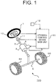
- FIG. 1 is a configuration diagram illustrating an electric power steering device according to a first embodiment of the present invention.
- the electric power steering device 100 includes a steering wheel 1, a steering shaft 2, a speed reduction device 3, a motor 4, a tie rod 5, a gear box (not shown), and a pair of steered wheels 6A and 6B.
- the steering wheel 1, the steering shaft 2, the tie rod 5, the gear box, and the pair of steered wheels 6A and 6B constitute a steering system.
- the steering wheel 1 is fixed to one end of the steering shaft 2. Moreover, the steering wheel 1 is operated by a driver.
- the speed reduction device 3 is attached to an intermediate portion of the steering shaft 2.
- the motor 4 is coupled to the steering shaft 2 via the speed reduction device 3.
- An intermediate portion of the tie road 5 is connected to the steering shaft 2 via the gear box.
- the pair of steered wheels 6A and 6B are rotatably attached to both ends of the tie rod 5. Steered angles of the pair of the steered wheels 6A and 6B change in response to a change in rotation angle of the steering wheel 1 operated by the driver.
- the drive torque of the motor 4 is amplified by the speed reduction device 3, and is applied to the steering shaft 2.
- a torque after the amplification by the motor 4 and the steering torque generated by the driver rotating the steering wheel 1 are applied to the steering shaft 2.
- the sum of the drive torque by the motor 4 and the steering torque rotates the steering shaft 2 and the steered wheels 6A and 6B against a road surface reaction force torque transmitted from the steered wheels 6A and 6B to the steering shaft 2.
- a steering angle sensor 10 is attached as steering angle detection means to the steering wheel 1.
- the steering angle sensor 10 generates a steering angle signal based on the steering angle of the steering wheel 1.
- a steering torque sensor 11 is attached as steering torque detection means to the steering shaft 2.
- the steering torque sensor 11 generates a steering torque signal based on the steering torque acting on the steering shaft 2.
- An operation of the electric power steering device 100 is controlled by a steering control device main unit 50.
- the steering angle signal from the steering angle sensor 10, the steering torque signal from the steering torque sensor 11, and a vehicle speed signal from a vehicle speed sensor 12 serving as vehicle speed detection means are input to the steering control device main unit 50.
- the steering control device main unit 50 monitors the steering angle, the steering torque, and the vehicle speed by using the steering angle signal, respectively, the steering torque signal, and the vehicle speed signal.
- the steering control device main unit 50 monitors a drive current of the motor 4. Further, the steering control device main unit 50 stores respective changes of the monitored steering angle, steering torque, vehicle speed, and drive current of the motor 4.
- the steering control device main unit 50 calculates an command current (steering assist current) required for generating the drive torque of the motor 4 based on the steering angle signal, the steering torque signal, and the vehicle speed signal. Moreover, the steering control device main unit 50 carries out current control (feedback control) so that the motor current based on the motor current signal coincides with the command current, and imparts an applied voltage obtained by the current control to the motor 4.
- command current steering assist current
- the steering control device main unit 50 carries out current control (feedback control) so that the motor current based on the motor current signal coincides with the command current, and imparts an applied voltage obtained by the current control to the motor 4.
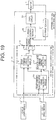
- FIG. 2 is a block diagram illustrating the steering control device main unit 50 of FIG. 1 .
- the steering control device main unit 50 includes an assist command current calculation module 51, a road surface reaction force torque calculation module 52, a reaction force command current calculation module 53, a subtraction module 54, a current control module 55, a drive circuit 56, and a current sensor 57 serving as current detection means.
- calculation processing of calculating the command current from the steering angle by the road surface reaction force torque calculation module 52, the reaction force command current calculation module 53, and the subtraction module 54 corresponds to filtering processing.
- the assist command current calculation module 51, the road surface reaction force torque calculation module 52, the reaction force command current calculation module 53, and the subtraction module 54 constitute a command current calculation system 60.
- the command current calculation system 60 calculates the command current.
- the assist command current calculation module 51 calculates a basic assist command current for reducing the steering torque by the driver by using the vehicle speed and the steering torque.
- an assist map as illustrated in FIG. 3 which shows values of the basic assist command current with respect to the vehicle speed and the steering torque, is registered in advance to the assist command current calculation module 51.
- the assist command current calculation module 51 calculates the basic assist command current by using the assist map, the vehicle speed, and the steering torque.
- a drive torque of the motor 4 corresponding to this basic assist command current is referred to as basic assist torque.
- the road surface reaction force torque calculation module 52 respectively calculates a caster-trail-caused torque M F , a self-aligning torque M S , and a road surface reaction force torque M R by using the vehicle speed, the steering angle, and vehicle models (types of filter) represented by equations (1) to (13) described later.
- the self-aligning torque M S includes a pneumatic-trail-caused torque M S1 generated by an uneven distribution of a tire lateral force F yF on the contact surface of the steered wheels 6A and 6B and a twist torque of tire M S2 as represented by the equation (9) described later.
- the reaction force command current calculation module 53 receives a calculation result of the road surface reaction force torque M R from the road surface reaction force torque calculation module 52. Moreover, the reaction force command current calculation module 53 calculates the reaction force command current by using the road surface reaction force torque M R and the vehicle speed. This reaction force command current is a current for adjusting the magnitude of the drive torque of the motor 4 so as to correspond to the magnitude of the road surface reaction force torque M R .
- the subtraction module 54 receives the calculation result of the basic assist command current from the assist command current calculation module 51. Moreover, the subtraction module 54 receives the calculation result of the reaction force command current from the reaction force command current calculation module 53. Further, the subtraction module 54 subtracts the reaction force command current from the basic assist command current, and transmits a current value obtained by the subtraction to the current control module 55 as a command current of the motor 4.
- the current control module 55 monitors the motor current via the current sensor 57. Moreover, the current control module 55 calculates an applied current of the motor 4 based on the command current and the motor current so that the current flowing through the motor 4 coincides with the command current.
- the drive circuit 56 carries out a pulse width modulation (PWM) drive so as to impart the applied voltage calculated by the current control module 55 to the motor 4.
- PWM pulse width modulation
- the steering control device main module 50 may be constituted by hardware (not shown) including an arithmetic processing device (CPU), a storage device (ROM, RAM, and the like), a signal input/output device, the drive circuit 56, and the current sensor 57.
- Programs for realizing functions of the assist command current calculation module 51, the road surface reaction force torque calculation module 52, the reaction force command current calculation module 53, the subtraction module 54, and the current control module 55 are stored in the storage device of this hardware.
- the command current calculation system 60 reads the vehicle speed V and the steering angle ⁇ h , and calculates the road surface reaction force torque M R by using the vehicle models represented by the following equations (1) to (13). Note that, these vehicle models are stored in the steering control device main unit 50 in advance. Moreover, various symbols (parameters) used for the calculation processing by the steering control device main unit 50 are defined as illustrated in FIG. 4 . Further, the various symbols used for the calculation processing by the steering control device main unit 50 correspond to vehicle models illustrated in FIGS. 5 to 8 .
- Models of a motion from the steering angle ⁇ h to the tire lateral force F yF generated on the steered wheels are represented by the following equations (1) to (6).
- a model of the road surface reaction force torque M R acting on the steering shaft 2 by the tire lateral force is represented by the following equation (7).
- the road surface reaction force torque M R includes the caster-trail-caused torque M F and the self-aligning torque M S , which is a moment about the vertical axis of the tire, as represented by this equation (7).
- the caster-trail-caused torque M F can be calculated by using the equation (8).
- the self-aligning torque M S can be calculated by using the equation (9).
- the self-aligning torque M S includes the pneumatic-trail-caused torque M S1 generated by the uneven distribution of the tire lateral force F yF on the contact surface of the steered wheels 6A and 6B and the twist torque of tire M S2 as represented by the equation (9).
- the pneumatic-trail-caused torque M S1 can be calculated by using the equation (10).
- the twist torque of tire M S2 can be modeled as represented by the equations (11) to (13).
- a gain constitutes a phase lead element based on tire twist stiffness, namely the gain constitutes a high-pass filter characteristic based on the tire twist stiffness, with respect to a front wheel lateral slip angle, thereby representing the twist torque of tire M S2 according to the equations (11) to (13).
- a tire twist response time constant T 1 is a time constant changing depending on the vehicle velocity, and can be set as represented by the equation (13).
- a tire twist response distance L 1 means a travel distance required for releasing a twist of the tire after steering.
- the road surface reaction force torque M R leads in phase with respect to the tire lateral force F yF in a steering frequency range, and has a characteristic that influence thereof is more remarkable in a low speed range.
- a coefficient "2" on the right side of the equations (8), (10), and (12) represents right and left wheels, namely two wheels in total. Further, the right sides of the equations (8), (10), and (12) are divided by an overall steering gear ratio G S to convert the road surface reaction force torque to a torque acting on the steering shaft 2.
- the overall steering gear ratio G S is designed so as to be variable depending on the steering angle, and an estimated rack shaft force value may be different from the road surface reaction force torque actually acting on the steering shaft from the road surface.
- the road surface reaction force torque actually acting on the steering shaft from the road surface can be accurately calculated by considering the overall steering gear ratio G S as in the equations (8), (10), and (12).
- the vehicle models represented by the equations (1) to (13) include the vehicle speed V as a parameter (variable) on this occasion. Therefore, the calculated results of the caster-trail-caused torque M F and the self-aligning torque M S change depending on the vehicle speed V.
- FIG. 9 is a flowchart illustrating the operation of the command current calculation system 60 of FIG. 2 .
- the command current calculation system 60 reads the stored vehicle speed, steering torque, and steering angle (Step S101). Then, the command current calculation system 60 calculates the basic assist command current by using the assist map and the read vehicle speed and steering torque (Step S102).
- the command current calculation system 60 calculates the command current by subtracting the reaction force command current I R from the basic assist command current (Step S106). Information on the calculated command current is transmitted to the current control module 55, and a current corresponding to the command current is controlled to flow through the motor 4 by the current control module 55. Then, the command current calculation system 60 repeats the processing in Steps S101 to S106.
- the conversion gain K 1 from the road surface reaction force torque M R to the reaction force command current I R is set in advance to values that vary depending on the vehicle speed as illustrated in FIG. 10 .
- a main purpose thereof is to reduce the steering torque at an extremely low speed range including 0 km/h of the vehicle speed. Therefore, the conversion gain K 1 is set so that the reaction force command current I R is 0 in the extremely low speed range.
- the steering torque decreases in the extremely low speed range, and operability is emphasized in the steering feeling in the extremely low speed range.
- the gradient of the steering torque with respect to the steering angle is basically small in a low speed range. Therefore, the conversion gain K 1 in the low speed range is set to a large value. As a result, the steering feeling improves. Further, the gradient of the steering torque with respect to the steering angle is basically large in a high speed range. Therefore, the conversion gain K 1 is set to a value smaller than that in the low speed range. As a result, the gradient of the steering torque with respect to the steering angle increases in an appropriate range.
- the conversion gain K 1 is set to values that vary depending on the vehicle speed in this way, and more appropriate operability is thus realized while a steering reaction force feeling (so-called on-center feeling) is improved.
- the steering feeling can be improved over the entire speed range by changing the conversion gain K 1 depending on the vehicle speed.
- the road surface reaction force torque M R is small.
- a ratio of a change in steering torque to a change in steering angle is small, resulting in an insufficient steering reaction force feeling. Therefore, the steering feeling degrades.
- Solid lines of FIGS. 11(a) and (b) represent frequency characteristics from the steering angle to the caster-trail-caused torque M F obtained from actually measured data at a vehicle speed of 40 km/h of an actual vehicle.
- Solid lines of FIGS. 11(c) and (d) represent frequency characteristics from the steering angle to the self-aligning torque M S obtained from actually measured data at the vehicle speed of 40 km/h of the actual vehicle.
- the caster-trail-caused torque M F (in phase with the tire lateral force F yF ) and the self-aligning torque M S are different in phase as illustrated in FIGS. 11 .
- the self-aligning torque M S leads in phase with respect to the caster-trail-caused torque M F .
- the self-aligning torque M S is larger in degree of decrease in gain around a steering frequency 2 Hz than the caster-trail-caused torque M F .
- the gain of the self-aligning torque M S is larger than the gain of the caster-trail-caused torque M F .
- the self-aligning torque M S is larger in ratio to the entire road surface reaction force torque M R than the caster-trail-caused torque M F .
- FIGS. 11(a) and (b) represent frequency responses from the steering angle to the caster trail caused torque M F in the vehicle models.
- FIGS. 11(c) and (d) represent frequency responses from the steering angle to the self-aligning torque M S in the vehicle models.
- the consideration of the twist torque of tire M S2 results in the self-aligning torque M S close to the actually measured value.
- the road surface reaction force torque M R which is the sum of the caster-trail-caused torque M F and the self-aligning torque M S , is also a vehicle model more close to an actually measured value. If the road surface reaction force torque M R is approximated by and calculated as M F +M S1 without considering the twist torque of tire M S2 as in the conventional case, a difference between the calculated road surface reaction force torque M R and the actual road surface reaction force torque M R is relatively large.
- FIG. 12(b) illustrates a characteristic that a solid line and a broken line coincide with each other.
- reaction force command current is calculated using the road surface reaction force torque M R , and the road surface reaction force torque M R is artificially increased (result of an increase in a steering reaction force torque by the road surface reaction force torque M R and the assist torque by the reaction force command current).
- FIGS. 12(c) and (d) represent frequency characteristics from the steering angle to the road surface reaction force torque M R obtained when the reaction force command current is 0.
- Solid lines of FIGS. 12(c) and (d) represent results obtained when the reaction force command current is calculated using M F +M S1 , and the road surface reaction force torque M R is artificially increased (result of an increase in the steering reaction force torque by the road surface reaction force torque M R and the assist torque by the reaction force command current).
- the increasing characteristic of the gain is almost equivalent to the characteristic represented by the solid line of FIG. 12(a) , but the phase lags behind the characteristic of the road surface reaction force torque M R represented by the broken line of FIG. 12(b) in a frequency range equal to or more than approximately 1 Hz.
- FIGS. 13 illustrate Lissajous waveforms of the steering torque with respect to the steering angle at a sinusoidal wave steering at 0.2 Hz (low frequency steering) at a vehicle velocity 40 km/h.
- This 0.2 Hz sinusoidal wave steering is a steering pattern corresponding to an ordinary lane change, and is frequently carried out.
- FIG. 13(a) is a result obtained when the steering by the driver is assisted based on the steering torque detected by the steering torque sensor 11 and the vehicle speed detected by the vehicle speed sensor 12.
- the Lissajous waveforms illustrated in FIGS. 13(b) to (d) represent control carried out based on the following specifications so that the gradients of the steering torque with respect to the steering angle close to the origin are the same.
- the Lissajous waveform of FIG. 13(b) represents a result of subtraction of a reaction force command current proportional to the steering angle from the basic assist command current. It is found that the gradient of the steering torque with respect to the steering angle is large, and the steering reaction force feeling is thus improved from FIG. 13(b) .
- the phase of the reaction force command current and the phase of the road surface reaction force torque in this case do not coincide with each other, and hence the hysteresis width of the Lissajous waveform becomes too narrow, resulting in degradation of the steering feeling.
- the Lissajous waveform of FIG. 13(c) is a result obtained when the motor 4 is driven by a command current obtained by subtracting a reaction force command current proportional to M F +M S1 in phase with the tire lateral force F YF from the basic assist command current.
- the gradients of the steering torque with respect to the steering angle close to the origin increase to a level as high as that of FIG. 13(b) on the Lissajous waveforms illustrated in FIGS. 13(c) and (d) , and it is thus found that the steering reaction force feeling is improved.
- the hysteresis widths of the Lissajous waveforms of FIGS. 13(c) and (d) are narrower than that of the Lissajous waveform of FIG. 13(a) , and are wider than that of the Lissajous waveform of FIG. 13(b) . From these facts, it is found that the friction feeling is proper, and natural steering feeling is realized.
- FIGS. 14 illustrate results of a sinusoidal steering at 2 Hz (high-frequency steering) at a vehicle speed of 40 km/h.
- the sinusoidal steering at 2 Hz corresponds to steering carried out when a vehicle makes a relatively quick lane change, or a vehicle returns to the center in a lane if the vehicle gets too close to one side in the lane.
- the sinusoidal steering at 2 Hz is a steering pattern relatively frequently carried out, though the sinusoidal steering at 2 Hz is not as frequent as the sinusoidal steering at 0.2 Hz.
- respective control specifications of FIGS. 14(a) to (d) are the same as the control specifications of FIGS. 13(a) to (d) .
- a Lissajous waveform of FIG. 14(a) represents a result obtained when the steering by the driver is assisted based on the steering torque and the vehicle speed. From FIG. 14(a) , the hysteresis width of the Lissajous waveform is large, and it is thus found that the friction feeling is remarkable. Moreover, the gradient of the steering torque with respect to the steering angle is small, and it is thus found that the steering reaction force feeling is insufficient. Further, the steering torque after a change in steering direction is approximately zero, and it is thus found that the reaction force torque for returning the steering wheel position to the center position is insufficient.
- the Lissajous waveform of FIG. 14(b) represents a result of subtraction of the reaction force command current proportional to the steering angle from the basic assist command current. From FIG. 14(b) , it is found that the steering torque is approximately 0 after the change in steering direction.
- the Lissajous waveform of FIG. 14(c) is a result obtained when the motor 4 is driven by a command current obtained by subtracting a reaction force command current proportional to M F +M S1 in phase with the tire lateral force F YF from the basic assist command current.
- the phase of M F +M S1 is different from the phase of the actual road surface reaction force torque. Therefore, the hysteresis width is extremely narrow in a neighborhood of the steering angle of 0 degrees. Moreover, the steering torque after the change in steering direction is approximately 0. In this way, for the control specifications illustrated in FIGS. 14(b) and (c) , the Lissajous waveforms are not smooth, and there arises a problem that non-smooth steering reaction force feeling is brought about.
- the steering control device main unit 50 carries out the filtering processing by means of the filter containing the predetermined frequency characteristics representing the vehicle characteristics from the steering angle to the self-aligning torque M S of the steered wheels 6A and 6B, and sets the drive torque of the motor 4 based on the result of the filtering processing.
- This configuration promotes the obtainment of the control effects which a designer wants to obtain, thereby realizing more natural steering feeling.
- the predetermined frequency characteristics of the filter contain the characteristic of the twist torque of tire M S2 .
- the steering control device main unit 50 calculates the road surface reaction force torque M R so as to be in phase with the actual road surface reaction force torque, and this configuration can thus increase the calculation accuracy of the road surface reaction force torque M R than the conventional device.
- the road surface reaction force torque M R can be accurately and artificially increased by correcting the drive torque of the motor 4 using the calculated road surface reaction force torque M R compared with the conventional device which does not consider the twist torque of tire M S2 .
- the driver carries out relatively quick steering such as a quick lane change, natural steering feeling close to the manual steering can be realized without a sense of discomfort.
- the steering control device main unit 50 carries out filtering processing on the steering angle signal using a filter including a predetermined frequency characteristic representing the vehicle characteristic from the steering angle to the pneumatic-trail-caused torque M S1 , thereby correcting the drive torque of the motor 4 based on a filtered result.
- This configuration can attain natural steering feeling without a sense of discomfort, and enables easy optimization of delicate steering feeling.
- the vehicle models represented by the equations (1) to (13) only need to be designed so as to be limited to the specific vehicle speed. A calculation load and a memory capacity for calculation can be reduced in this case.
- the road surface reaction force torque calculation module 52 calculates the reaction force command current by multiplying the road surface reaction force M R by the conversion gain K 1 .
- the road surface reaction force torque calculation module 52 calculates the reaction force command current I R by respectively multiplying the caster-trail-caused torque M F and the self-aligning torque M S by conversion gains K 1 and K 2 , and obtaining a sum of the products.
- the schematic configuration of the steering control device main unit 50 according to the second embodiment is the same as the steering control device main unit 50 according to the first embodiment. Parts of contents of processing by the road surface reaction force torque calculation module 52 and the reaction force command current calculation module 53 of the steering control device main unit 50 according to the second embodiment are different from those by the road surface reaction force torque calculation module 52 and the reaction force command current calculation module 53 according to the first embodiment. On this occasion, a description is mainly given of the difference from the first embodiment.
- the road surface reaction force torque calculation module 52 takes in the vehicle speed signal and the steering angle signal. Moreover, the road surface reaction force toque calculation module 52 respectively calculates the caster-trail-caused torque M F and the self-aligning torque M S using the vehicle speed signal, the steering angle signal, and the vehicle models represented by the equations (1) to (13).
- a conversion gain map for the conversion gains K 1 and K 2 as the predetermined gains are registered in advance to the steering control device main unit 50 according to the second embodiment as illustrated in FIG. 10 according to the first embodiment.
- the conversion gains K 1 and K 2 are values for respectively converting the caster-trail-caused torque M F and the self-aligning torque M S to the reaction force command current.
- values that vary depending on the vehicle speed are set to the conversion gains K 1 and K 2 as in the conversion gain K 1 according to the first embodiment.
- the reaction force command current calculation module 53 sets the conversion gains K 1 and K 2 using the conversion gain map and the vehicle speed when the reaction force command current I R is calculated. Moreover, the reaction force command current calculation module 53 calculates the reaction force command current I R by respectively multiplying the caster-trail-caused torque M F and the self-aligning torque M S calculated by the road surface reaction force torque calculation module 52 by the conversion gains K 1 and K 2 , and obtaining the sum of the products.
- a main object is to reduce the steering torque in the extremely low speed range of the vehicle speed including 0 km/h, the steering torque can be reduced by setting the reaction force command current to 0, resulting in steering feeling emphasizing the operability.
- the gradient of the steering torque with respect to the steering angle is originally small in a low speed range, and the steering feeling can be improved by setting large values to the conversion gains K 1 and K 2 .
- the gradient of the steering torque with respect to the steering angle is originally large in a high speed range, and the gradient of the steering torque with respect to the steering angle can be increased in a proper range by setting the conversion gains K 1 and K 2 to values smaller than those in the low speed range, thereby providing proper operability while the reaction force feeling (so-called on-center feeling) is improved.
- the steering feeling can be improved across the entire vehicle speed range by changing K 1 and K 2 depending on the vehicle speed in this way. Note that, different values can respectively be set to the conversion gains K 1 and K 2 .
- map values (limit value setting map) relating to limit values with respect to the vehicle speed are registered in advance to the steering control device main unit 50 as illustrated in FIG. 15 .
- the reaction force command current calculation module 53 sets the limit value depending on the vehicle speed. Moreover, the reaction force command current calculation module 53 calculates the reaction force command current I R , and then applies the limit so that the magnitude of the reaction force command current I R is within the set limit value.
- the relationship between the pneumatic-trail-caused torque M S1 and the twist torque of tire M S2 is a relationship represented by the following equation (15) based on the equations (1) to (13).
- a relationship between a front wheel sideslip angle ⁇ f and the twist torque of tire M S2 represented by the following equation (16) is a relationship represented by the following equation (17).
- s denotes the Laplacian operator in the equations (15) and (17). [Math.
- the road surface reaction force torque calculation module 52 may apply low-pass filtering processing represented by the following equation (18), for example, to the twist torque M S2 .
- s denotes the Laplacian operator in the equation (18).
- a time constant T 2 of the low-pass filter is set in advance to a value which is equal to or more than 5 Hz, which is a limit for human steering frequency, and is also equal to or more than a frequency band affecting the steering feeling.
- the upper limit is set in advance to a Nyquist frequency for the calculation period of the road surface reaction force torque 52.
- FIG. 16 is a flowchart illustrating the operation of the command current calculation system 60 according to the second embodiment of the present invention.
- the command current calculation system 60 reads the stored vehicle speed, steering torque, and steering angle (Step S201). Then, the command current calculation system 60 calculates the basic assist command current using the assist map and the read vehicle speed and steering torque (Step S202).
- the command current calculation system 60 calculates the caster-trail-caused torque M F and the self-aligning torque M S using the read vehicle speed and steering angle, and the vehicle models represented by the equations (1) to (13) (Step S203). Then, the command current calculation system 60 sets the conversion gains K 1 and K 2 using the conversion gain map (see FIG. 10 ) set in advance and the vehicle speed (Step S204).
- the command current calculation system 60 limits the calculated reaction force command current I R within the limit value (Step S206). Then, the command current calculation system 60 calculates the command current by subtracting the reaction force command current I R from the basic assist command current (Step S207). Information on the calculated command current is transmitted to the current control module 55, and the current control module 55 performs the control to cause a current, the magnitude of which is set based on the command current, to flow through the motor 4. Then, the command current calculation system 60 repeats the processing in Steps S201 to S206.
- FIGS. 17 are explanatory diagrams illustrating the steering control device main unit 50 according to second embodiment of the present invention.
- a Lissajous waveform of FIG. 17(a) represents a result of a sinusoidal wave steering at 0.2 Hz at 40 km/h when the motor 4 is driven by the command current obtained by subtracting the reaction force command current proportional to the self-aligning torque M S from the basic assist command current.
- a Lissajous waveform of FIG. 17(b) represents a result of a sinusoidal wave steering at 2 Hz when the motor 4 is driven by the command current obtained by subtracting the reaction force command current proportional to the self-aligning torque M S from the basic assist command current. From FIG. 17(b) , it is found that the change rate of the steering torque with respect to the steering angle in a neighborhood of 0 degrees increases, and more proper steering reaction force feeling is thus realized. Moreover, it is found that the steering torque after the change in steering direction is not close to 0, and a smooth Lissajous waveform is brought about. Further, it is found that a proper hysteresis width is provided, resulting in a reduction in the friction feeling.
- the gain of the self-aligning torque M S is larger than that of the caster-trail-caused torque M F , and the self-aligning torque M S occupies a larger ratio in the road surface reaction force torque M R . Therefore, even if the reaction force command current I R is calculated based on the self-aligning torque M S , a Lissajous waveform equivalent to a result of the calculation of the reaction force command current I R based on the road surface reaction force torque M R can be obtained, and an effect similar to that of the first embodiment can be obtained.
- the second embodiment it is possible to calculate a road surface reaction force torque M R closer to an actual value than the conventional electric power steering device, and to impart the current to the motor 4 based on the calculated self-aligning torque M S .
- the steering characteristic of the manual steering which a control designer tries to obtain can be emphasized.
- natural steering feeling without a sense of discomfort can be realized from the low-frequency steering range to the high-frequency steering range.
- the command current calculation system 60 calculates the reaction force command current I R by obtaining the sum of the caster-trail-caused torque M F multiplied by the conversion gain K 1 and the self-aligning torque M S multiplied by the conversion gain K 2 .
- This configuration can adjust the ratio between the caster-trail-caused torque M F and the self-aligning torque M S occupying the road surface reaction force torque to be artificially increased.
- the gradient of the steering torque with respect to the steering angle (steering reaction force feeling) and the hysteresis width (friction feeling) in a neighborhood of the origin in the Lissajous waveform can be independently adjusted.
- the hysteresis width of the Lissajous waveform can be slightly reduced by setting K 1 larger than K 2 in this case. As a result, delicate steering feeling can be easily optimized while natural steering feeling without a sense of discomfort close to the manual steering is realized.
- the reaction force command current calculation module 53 obtains the reaction force command current I R by respectively multiplying the torque M F and M S by the conversion gains K 1 and K 2 as represented by the equation (19).
- how to obtain the reaction force command current I R is not limited to this example, and the reaction force command current I R may be registered in advance to the command current calculation system 60 as a map value with respect to the caster-trail-caused torque M F , the self-aligning torque M S , or the road surface reaction force torque M R , and the vehicle speed.
- the assist command current calculation module 51 calculates the basic assist command current based on the vehicle speed and the steering torque.
- the steering torque sensor 11 according to the first embodiment is omitted, and the assist command current calculation module 51 calculates the basic assist command current based on the road surface reaction force torque M R calculated by the road surface reaction force torque calculation module 52, and the vehicle speed.
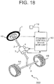
- FIG. 18 is a configuration diagram illustrating an electric power steering device according to the third embodiment of the present invention.
- the overview of the configuration of the electric power steering device 100 according to the third embodiment is the same as the configuration of the electric power steering device 100 according to the first embodiment.
- the configuration of the electric power steering device 100 according to the third embodiment is different from the electric power steering device 100 according to the first embodiment in that the steering torque sensor 11 according to the first embodiment is omitted.
- FIG. 19 is a block diagram illustrating the steering control device main unit 50 of FIG. 18 .
- the schematic configuration of the steering control device main unit 50 according to the third embodiment is the same as the steering control device main unit 50 according to the first embodiment.
- the steering control device main unit 50 according to the third embodiment is different from the steering control device main module 50 in that the assist command current calculation module 51 receives the calculation result of the road surface reaction force torque from the road surface reaction force torque calculation module 52 in place of the steering torque signal from the steering torque sensor 11.
- the assist command current calculation module 51 calculates the basic assist command current based on the road surface reaction force torque M R calculated by the road surface reaction force torque calculation module 52 and the vehicle speed. On this occasion, values of the basic assist command current with respect to the vehicle speed and the road surface reaction force torque, for example, are stored as an assist map in the steering control device main unit 50 according to the third embodiment.
- the assist command current calculation module 51 calculates a basic assist command current corresponding to the vehicle speed and the road surface reaction force torque by using the assist map.
- the other configuration and operation are the same as those in the first embodiment.
- the twist torque of tire M S2 is included in the road surface reaction force torque M R acting on the steering shaft 2. Therefore, even the configuration without the steering torque sensor 11 can carry out proper assist control for a change in the steering torque generated by the twist of the tires themselves.
- the assist command current calculation module 51 may be omitted.
- the reaction force command current calculated by the reaction force command current calculation module 53 may be used as the command current of the motor 4.
- the present invention can be applied to a steering device employing a system such as a steer-by-wire system in which a steering wheel and steered wheels are not mechanically coupled, and the road surface reaction force torque is not transmitted to the steering wheel.
- the reaction force command current calculated by the reaction force command current calculation module 53 may be used as the command current of the motor attached to a steering wheel side.
- the reaction force command current calculation module 53 calculates the reaction force command current I R using the road surface reaction force torque M R and the vehicle speed. In contrast, according to a fourth embodiment, the reaction force command current calculation module 53 calculates the reaction force command current I R using the road surface reaction force torque M R and the vehicle speed, and corrects the reaction force command current I R using the steering torque.
- FIG. 20 is a block diagram illustrating the steering control device main unit 50 according to the fourth embodiment of the present invention.
- FIG. 21 is an explanatory diagram for describing the correction processing for the reaction force command current by the reaction force command current calculation module 53 of FIG. 20 .
- the reaction force current calculation module 53 calculates the reaction force command current I R as in the first and second embodiments. Moreover, the reaction force command current calculation module 53 includes an absolute value calculation module 53a, a correction gain setting module 53b, and a multiplication module 53c.
- the absolute value calculation module 53a receives the steering torque signal from the steering torque sensor 11, and calculates the absolute value of the steering torque.
- a correction gain map which includes map values of the correction gain to the steering torque is registered in advance to the correction gain setting module 53b.
- the correction gain map is registered so as to reduce the correction gain with respect to an increase in steering torque.
- the correction gain setting module 53b sets the correction gain corresponding to the absolute value of the steering torque calculated by the absolute value calculation module 53a based on the correction gain map.
- the multiplication module 53c corrects the reaction force command current I R calculated by the reaction force command current calculation module 53 as in the first and second embodiments by multiplying the reaction force command current I R by the correction gain set by the steering torque.
- the other configuration and operation are the same as those in the first and second embodiments.
- the correction gain map is registered so as to reduce the correction gain with respect to the increase in steering torque.
- the reaction force command current can be reduced to restrain the steering torque from increasing in a region where the steering torque is sufficiently large, and imparting the road surface reaction force torque is not necessary.
- the correction gain does not decrease, and the imparted road surface reaction force torque can be maintained.
- the correction gain is registered to the correction gain setting module 53b while the correction gain is associated with the steering torque.
- the reaction force command current calculation module 53 can calculate the steering speed from the steering angle signal, and a correction gain based on the steering speed may be registered in advance to the correction gain setting module 53b.
- a setting in which the correction gain decreases as the steering speed increases is provided, for example, in a state in which a driver has to steer over a large steering angle in a short period, though the reaction force command current is reduced, resulting in a decrease in reaction force feeling, the steering can be carried out using a small steering torque.
- the correction gain corresponding to the steering angle may be registered in advance to the correction gain setting module 53b.
- a difference in road surface reaction force torque characteristic between the left and right directions, which the vehicle originally has, can be restrained by setting the correction gain to different values respectively for the steering in the left and right directions.
- the left/right steering directions can be determined based on the sign (+/-) of the steering torque, and different correction gains can be set depending on the sign of the steering torque.
- the road surface reaction force torque calculation module 52 corrects the vehicle models represented by the equations (1) to (13) based on the vehicle weight or the road surface friction coefficient.
- the schematic configuration of the steering control device main unit 50 according to the fifth embodiment is the same as the schematic configuration of the steering control device main unit 50 according to the first embodiment. Moreover, the steering control device main unit 50 according to the fifth embodiment is different from the steering control device main unit 50 according to the first embodiment in that a vehicle weight sensor 13 and a road surface friction coefficient sensor 14 are connected, and in internal processing of the road surface reaction force torque calculation module 52. On this occasion, a description is mainly given of the difference from the first embodiment.
- FIG. 22 is a block diagram illustrating the steering control device main unit 50 according to the fifth embodiment of the present invention.
- the vehicle weight sensor 13 serving as vehicle weight acquisition means detects or estimates a vehicle weight m, and generates a vehicle weight signal based on the vehicle weight m.
- the road surface friction coefficient sensor 14 serving as road surface friction coefficient acquisition means detects or estimates a road surface friction coefficient or a physical quantity corresponding thereto, thereby generating a road surface friction coefficient signal.
- the arithmetic expressions of the vehicle models represented by the equations (1) to (13) contain the vehicle weight m as a parameter (variable).
- the road surface reaction force calculation module 52 monitors a change in the vehicle weight m using the vehicle weight signal from the vehicle weight sensor 13, and changes the characteristics of the vehicle models based on the vehicle weight m.
- the change in the vehicle weight m mainly includes changes caused by weights of passengers, loads, and fuel, and a sprung mass m s of the vehicle models represented by the equations (1) to (13) may be changed based on the vehicle weight m.
- the vehicle weight m and the sprung mass m s which are considered as fixed values according to the first embodiment, are considered as variables according to the fifth embodiment.
- cornering powers K f and K r of the front and rear wheels change depending on the vehicle weight and the road surface friction coefficient. Therefore, the road surface reaction force calculation module 52 changes the cornering powers K f and K r of the vehicle models based on the vehicle weight and the road surface friction coefficient. For example, the cornering powers K f and K r of the vehicle models may be set to increase in response to an increase in vehicle weight, for example. Further, the cornering powers K f and K r of the vehicle models may be set to decrease on a road surface which is low in road surface friction coefficient, and is thus slippery.
- the road surface reaction force torque M R closer to the actual road surface reaction force torque, which ranges from the steering angle to the self-aligning torque M S can be calculated considering also the case where the vehicle weight largely changes and the case where the vehicle travels on a slippery surface.
- the road surface reaction force torque M R considering changes in the vehicle weight and the road surface can be artificially increased, resulting in more natural steering feeling.
- the cornering powers K f and K r of the vehicle models are changed based on both the vehicle weight and the road surface friction coefficient.
- what is used to change the cornering powers K f and K r is not limited to this example, the cornering powers K f and K r of the vehicle models may be changed based on only any one of the vehicle weight and the road surface friction coefficient.
- the filter may be set to change depending on at least one of the vehicle speed of the vehicle, the steering torque, the steering angle, the vehicle weight, the road surface friction coefficient, the steering speed, and the steering direction.
- the filter may be set to change depending on at least one of the vehicle speed of the vehicle, the steering torque, the steering angle, the vehicle weight, the road surface friction coefficient, the steering speed, and the steering direction.
- the vehicle models represented by the equations (1) to (13) are used for calculating the self-aligning torque M S .
- what is used to calculate the self-aligning torque M S is not limited to this example.
- a vehicle model registered in advance may be identified based on the measured steering angle and the measured self-aligning torque without using the vehicle models represented by the equations (1) to (13), and the reaction force command current may be calculated using the identified vehicle model. Also in that case, the same effects as those of the first to fifth embodiments may be obtained.
- the steering control device main unit 50 monitors the change in the steering angle via the steering angle sensor 10.
- the rotation angle of the motor 4 and the rotation angles (steered angles) of the steered wheels 6A and 6B are physical quantities changing in response to the steering angle.
- the steering control device main module 50 may monitor a change in the steering angle by monitoring changes in these physical quantities not via the steering angle sensor 10 (but via other sensors).
- the assist torque generated by the motor 4 is calculated based on the reaction force command current and the basic assist command current.
- how to calculate the assist torque is not limited to this example, and the assist torque according to the first to fifth embodiments may be replaced by various motor-generated torques based on the self-aligning torque M S or the road surface reaction force torque M R calculated using the vehicle models represented by the equations (1) to (13).
Landscapes
- Engineering & Computer Science (AREA)
- Chemical & Material Sciences (AREA)
- Combustion & Propulsion (AREA)
- Transportation (AREA)
- Mechanical Engineering (AREA)
- Steering Control In Accordance With Driving Conditions (AREA)
- Power Steering Mechanism (AREA)
Description
- The present invention relates to a steering control device for controlling drive of a motor for imparting a power to a steering system in response to a steering operation of a driver.
- An electric power steering device, which detects a steering torque and imparts an assist torque (steering assist torque) based on the steering torque, is known as a general steering device. A steering control device for controlling drive of the electric power steering device of this type controls the steering torque sensed by the driver steering the steering wheel, and thus constitutes an important factor forming steering feeling of a vehicle.
- On this occasion, a road surface reaction force torque is a torque acting in a direction of returning the steering wheel to a neutral point by a tire lateral force acting between the road surface and steered wheels. The road surface reaction force torque may be small depending on a layout of the steering system, specifications of tires, and the like on some vehicles.
- When the road surface reaction force torque is small in this way, the road surface reaction force torque cannot overcome a friction torque, which is relatively large. As a result, the road surface reaction force torque acting in the direction in which the steering wheel is returned to the neutral point becomes insufficient during the steering by the driver. It is thus necessary for the driver to intentionally apply a return torque to the steering wheel, thereby returning the steering wheel to the neutral point.
- Moreover, when the road surface reaction force torque is small, it is difficult for the driver to sense, based on a reaction force transmitted to the hands of the driver, whether the steering wheel is at the neutral point, or the steering wheel is displaced from the neutral point and the vehicle is thus turning. It is thus necessary for the driver to visually confirm the steering wheel position so that the vehicle is stably controlled to travel straight. As described above, in a case where the road surface reaction force torque is small, there has been a problem that the steering feeling decreases.
- In order to address this problem, an electronic control unit (ECU) drives a motor so as to impart a steering wheel return torque based on a steering angle and a direction of a steering angular velocity to a steering system in a conventional device described in
Patent Literature 1, for example. - Moreover, an ECU estimates a rack shaft force from a steering angle based on a vehicle model, and carries out assist control based on the estimated rack shaft force value in a conventional device described in
Patent Literature 2, for example. - Further, an ECU calculates an assist torque by using a result obtained by subtracting a steady-state response component, which can be mathematically calculated, from a steering response characteristic represented as a vehicle model out of response characteristics of the steering torque with respect to a steering angle in a conventional device described in
Patent Literature 3, for example. This calculated assist torque cancels a characteristic of a high frequency component (non-steady state response component) out of the response characteristics of the steering torque with respect to the steering angle. - Moreover, an ECU compensates, in phase, a detected or estimated self-aligning torque in order to compensate a cornering force affected by a suspension geometry and a transmission delay of a self-aligning torque dynamic characteristic, and corrects a steering assist command value in a conventional device described in Patent Literature 4), for example.
-
- [PTL 1]:
JP 2002-145100 A FIG. 2 ) - [PTL 2]:
JP 2007-269251 A FIG. 2 ) - [PTL 3]:
JP 2004-338616 A FIG. 2 ) - [PTL 4]:
JP 2008-114687 A FIG. 11 ) -
US-A1-2007/0273317 discloses a control apparatus of an electric power steering apparatus constructed so as to calculate a current command value of a motor for applying steering assist force to a steering mechanism based on steering torque and a vehicle speed and drive and control the motor based on the current command value, there are provided an SAT detection part for detecting or estimating an SAT detection value, a standard SAT calculation part for calculating a standard SAT value based on a steering angle and the vehicle speed, and a correction part for calculating a correction amount based on the SAT detection value and the standard SAT value and correcting the current command value. - In the conventional devices described above, the assist torque is set based on the steering angle or a road surface reaction force torque (corresponding to the rack shaft force according to
Patent Literature 2, and the steering torque by the manual steering according to Patent Literature 3) which is calculated from the steering angle by using the vehicle model. However, in the conventional devices, influence of a torque (MS2: hereinafter, referred to as "twist torque of tire") transitionally generated by the tires themselves, which constitute a part of the steered wheels, elastically being deformed when a lateral slip angle is generated on the steered wheels is not considered in the vehicle model mathematically representing physical characteristics (transmission characteristics) of the vehicle from the steering angle to the road surface reaction force torque. - Specifically, in the conventional device, a calculated road surface reaction force torque (MR) is approximated as a sum of a torque (MF: hereinafter, referred to as caster-trail-caused torque) generated by a caster trail and a tire lateral force and a torque (MS1: hereinafter, referred to as pneumatic-trail-caused torque) generated by an uneven distribution of the tire lateral force on the contact surface of the steered wheels. As a result, the road surface reaction force torque (MR) is a state quantity in phase with the tire lateral force (FyF).
- On this occasion, the road surface reaction force torque (MR) has a feature of leading in phase with respect to the tire lateral force (FyF) in a steering frequency domain. Therefore, the road surface reaction force torque calculated by using the steering angle or the road surface reaction force torque calculated by using the steering angle and the vehicle model is different from the road surface reaction force torque actually acting on the steering shaft from the road surface.
- Thus, the road surface reaction force torque which is different from the actual road surface reaction force torque is used to design the assist torque for the electric power steering device in the conventional devices. As a result, a control effect which a control designer intends to obtain is not sufficiently exerted, resulting in failure in realizing natural steering feeling in the conventional devices.
- The present invention has been made in view of the above-mentioned problem, and therefore has an object to provide a steering control device capable of providing a control effect intended by a designer more easily and of realizing more natural steering feeling.
- The present invention provides a steering control device according to
Claim 1. -
- [
FIG. 1 ] A configuration diagram illustrating an electric power steering device according to a first embodiment of the present invention. - [
FIG. 2 ] A block diagram illustrating a steering control device main unit ofFIG. 1 . - [
FIG. 3 ] A chart illustrating an example of an assist map. - [
FIG. 4 ] An explanatory diagram describing definitions of various symbols. - [
FIG. 5 ] A schematic diagram representing a four-wheel vehicle as an equivalent two-wheel model. - [
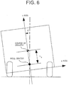
FIG. 6 ] A schematic diagram illustration a rotation movement about an x axis of a vehicle. - [
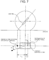
FIG. 7 ] A schematic diagram illustrating a tire model. - [
FIG. 8 ] A schematic diagram illustrating a tire stiffness. - [
FIG. 9 ] A flowchart illustrating an operation of a command current calculation system ofFIG. 2 . - [
FIG. 10 ] A chart illustrating an example of a conversion gain map. - [
FIGS. 11 ] Charts illustrating frequency characteristics based on a measured value and a frequency response for vehicle models. - [
FIGS. 12 ] Charts representing frequency characteristics for describing an effect for a case where a reaction force command current is calculated based on a road surface reaction force torque. - [
FIGS. 13 ] Lissajous waveforms of a steering torque with respect to the steering angle at a sinusoidal wave steering at 0.2 Hz, and at a vehicle speed of 40 km/h. - [
FIGS. 14 ] Lissajous waveforms of the steering torque with respect to the steering angle at a sinusoidal wave steering at 2 Hz, and a vehicle speed of 40 km/h. - [
FIG. 15 ] A chart illustrating an example of a limit value setting map according to a second embodiment of the present invention. - [
FIG. 16 ] A flowchart illustrating an operation of the command current calculation system according to the second embodiment of the present invention. - [
FIGS. 17 ] Explanatory diagrams illustrating an effect of the steering control device main unit according to the second embodiment of the present invention. - [
FIG. 18 ] A configuration diagram illustrating an electric power steering device according to a third embodiment of the present invention. - [
FIG. 19 ] A block diagram illustrating the steering control device main unit ofFIG. 18 . - [
FIG. 20 ] A block diagram illustrating a steering control device main unit according to a fourth embodiment of the present invention. - [
FIG. 21 ] An explanatory diagram for describing correction processing for a reaction force command current by a reaction force command current calculation module ofFIG. 20 . - [
FIG. 22 ] A block diagram illustrating a steering control device main unit according to a fifth embodiment of the present invention. - A description is now given of embodiments of the present invention referring to the drawings.
-
FIG. 1 is a configuration diagram illustrating an electric power steering device according to a first embodiment of the present invention. - In
FIG. 1 , the electricpower steering device 100 includes asteering wheel 1, asteering shaft 2, aspeed reduction device 3, amotor 4, atie rod 5, a gear box (not shown), and a pair of steeredwheels steering wheel 1, thesteering shaft 2, thetie rod 5, the gear box, and the pair of steeredwheels steering wheel 1 is fixed to one end of thesteering shaft 2. Moreover, thesteering wheel 1 is operated by a driver. - The
speed reduction device 3 is attached to an intermediate portion of thesteering shaft 2. Themotor 4 is coupled to thesteering shaft 2 via thespeed reduction device 3. An intermediate portion of thetie road 5 is connected to thesteering shaft 2 via the gear box. The pair of steeredwheels tie rod 5. Steered angles of the pair of the steeredwheels steering wheel 1 operated by the driver. - The drive torque of the
motor 4 is amplified by thespeed reduction device 3, and is applied to thesteering shaft 2. Thus, a torque after the amplification by themotor 4 and the steering torque generated by the driver rotating thesteering wheel 1 are applied to thesteering shaft 2. The sum of the drive torque by themotor 4 and the steering torque rotates thesteering shaft 2 and the steeredwheels wheels steering shaft 2. - A
steering angle sensor 10 is attached as steering angle detection means to thesteering wheel 1. Thesteering angle sensor 10 generates a steering angle signal based on the steering angle of thesteering wheel 1. Asteering torque sensor 11 is attached as steering torque detection means to thesteering shaft 2. Thesteering torque sensor 11 generates a steering torque signal based on the steering torque acting on thesteering shaft 2. - An operation of the electric
power steering device 100 is controlled by a steering control devicemain unit 50. The steering angle signal from thesteering angle sensor 10, the steering torque signal from thesteering torque sensor 11, and a vehicle speed signal from avehicle speed sensor 12 serving as vehicle speed detection means are input to the steering control devicemain unit 50. The steering control devicemain unit 50 monitors the steering angle, the steering torque, and the vehicle speed by using the steering angle signal, respectively, the steering torque signal, and the vehicle speed signal. Moreover, the steering control devicemain unit 50 monitors a drive current of themotor 4. Further, the steering control devicemain unit 50 stores respective changes of the monitored steering angle, steering torque, vehicle speed, and drive current of themotor 4. - Moreover, the steering control device
main unit 50 calculates an command current (steering assist current) required for generating the drive torque of themotor 4 based on the steering angle signal, the steering torque signal, and the vehicle speed signal. Moreover, the steering control devicemain unit 50 carries out current control (feedback control) so that the motor current based on the motor current signal coincides with the command current, and imparts an applied voltage obtained by the current control to themotor 4. -
FIG. 2 is a block diagram illustrating the steering control devicemain unit 50 ofFIG. 1 . InFIG. 2 , the steering control devicemain unit 50 includes an assist commandcurrent calculation module 51, a road surface reaction forcetorque calculation module 52, a reaction force commandcurrent calculation module 53, asubtraction module 54, acurrent control module 55, adrive circuit 56, and acurrent sensor 57 serving as current detection means. On this occasion, calculation processing of calculating the command current from the steering angle by the road surface reaction forcetorque calculation module 52, the reaction force commandcurrent calculation module 53, and thesubtraction module 54 corresponds to filtering processing. - The assist command
current calculation module 51, the road surface reaction forcetorque calculation module 52, the reaction force commandcurrent calculation module 53, and thesubtraction module 54 constitute a commandcurrent calculation system 60. The commandcurrent calculation system 60 calculates the command current. - The assist command
current calculation module 51 calculates a basic assist command current for reducing the steering torque by the driver by using the vehicle speed and the steering torque. Specifically, an assist map as illustrated inFIG. 3 , which shows values of the basic assist command current with respect to the vehicle speed and the steering torque, is registered in advance to the assist commandcurrent calculation module 51. The assist commandcurrent calculation module 51 calculates the basic assist command current by using the assist map, the vehicle speed, and the steering torque. A drive torque of themotor 4 corresponding to this basic assist command current is referred to as basic assist torque. - The road surface reaction force
torque calculation module 52 respectively calculates a caster-trail-caused torque MF, a self-aligning torque MS, and a road surface reaction force torque MR by using the vehicle speed, the steering angle, and vehicle models (types of filter) represented by equations (1) to (13) described later. Note that, the self-aligning torque MS includes a pneumatic-trail-caused torque MS1 generated by an uneven distribution of a tire lateral force FyF on the contact surface of the steeredwheels - The reaction force command
current calculation module 53 receives a calculation result of the road surface reaction force torque MR from the road surface reaction forcetorque calculation module 52. Moreover, the reaction force commandcurrent calculation module 53 calculates the reaction force command current by using the road surface reaction force torque MR and the vehicle speed. This reaction force command current is a current for adjusting the magnitude of the drive torque of themotor 4 so as to correspond to the magnitude of the road surface reaction force torque MR. - The
subtraction module 54 receives the calculation result of the basic assist command current from the assist commandcurrent calculation module 51. Moreover, thesubtraction module 54 receives the calculation result of the reaction force command current from the reaction force commandcurrent calculation module 53. Further, thesubtraction module 54 subtracts the reaction force command current from the basic assist command current, and transmits a current value obtained by the subtraction to thecurrent control module 55 as a command current of themotor 4. - The
current control module 55 monitors the motor current via thecurrent sensor 57. Moreover, thecurrent control module 55 calculates an applied current of themotor 4 based on the command current and the motor current so that the current flowing through themotor 4 coincides with the command current. Thedrive circuit 56 carries out a pulse width modulation (PWM) drive so as to impart the applied voltage calculated by thecurrent control module 55 to themotor 4. - On this occasion, the steering control device
main module 50 may be constituted by hardware (not shown) including an arithmetic processing device (CPU), a storage device (ROM, RAM, and the like), a signal input/output device, thedrive circuit 56, and thecurrent sensor 57. Programs for realizing functions of the assist commandcurrent calculation module 51, the road surface reaction forcetorque calculation module 52, the reaction force commandcurrent calculation module 53, thesubtraction module 54, and thecurrent control module 55 are stored in the storage device of this hardware. - A more specific description is now given of the calculation processing by the command
current calculation system 60. The commandcurrent calculation system 60 reads the vehicle speed V and the steering angle θh, and calculates the road surface reaction force torque MR by using the vehicle models represented by the following equations (1) to (13). Note that, these vehicle models are stored in the steering control devicemain unit 50 in advance. Moreover, various symbols (parameters) used for the calculation processing by the steering control devicemain unit 50 are defined as illustrated inFIG. 4 . Further, the various symbols used for the calculation processing by the steering control devicemain unit 50 correspond to vehicle models illustrated inFIGS. 5 to 8 . - Models of a motion from the steering angle θh to the tire lateral force FyF generated on the steered wheels are represented by the following equations (1) to (6).
- Conversion from the steering angle θh to a steered angle δ of the steered wheels:
[Math. 1]
- An equation of motion in a y axis (lateral) direction of the vehicle:
[Math. 2]
- An equation of rotational motion about a z axis (vertical direction axis):
[Math. 3]
- An equation of rotational motion about an x axis (chassis longitudinal axis):
[Math. 4]
- A tire lateral force (cornering force) generation model:
[Math. 5]

- A model of the road surface reaction force torque MR acting on the
steering shaft 2 by the tire lateral force is represented by the following equation (7).
[Math. 6]


- The road surface reaction force torque MR includes the caster-trail-caused torque MF and the self-aligning torque MS, which is a moment about the vertical axis of the tire, as represented by this equation (7). The caster-trail-caused torque MF can be calculated by using the equation (8). The self-aligning torque MS can be calculated by using the equation (9).
- Further, the self-aligning torque MS includes the pneumatic-trail-caused torque MS1 generated by the uneven distribution of the tire lateral force FyF on the contact surface of the steered
wheels - The twist torque of tire MS2 can be modeled as represented by the equations (11) to (13). A gain constitutes a phase lead element based on tire twist stiffness, namely the gain constitutes a high-pass filter characteristic based on the tire twist stiffness, with respect to a front wheel lateral slip angle, thereby representing the twist torque of tire MS2 according to the equations (11) to (13).
- Note that, a tire twist response time constant T1 is a time constant changing depending on the vehicle velocity, and can be set as represented by the equation (13). Moreover, a tire twist response distance L1 means a travel distance required for releasing a twist of the tire after steering. Further, the road surface reaction force torque MR leads in phase with respect to the tire lateral force FyF in a steering frequency range, and has a characteristic that influence thereof is more remarkable in a low speed range.
- Moreover, a coefficient "2" on the right side of the equations (8), (10), and (12) represents right and left wheels, namely two wheels in total. Further, the right sides of the equations (8), (10), and (12) are divided by an overall steering gear ratio GS to convert the road surface reaction force torque to a torque acting on the
steering shaft 2. - Moreover, in some cases, the overall steering gear ratio GS is designed so as to be variable depending on the steering angle, and an estimated rack shaft force value may be different from the road surface reaction force torque actually acting on the steering shaft from the road surface. The road surface reaction force torque actually acting on the steering shaft from the road surface can be accurately calculated by considering the overall steering gear ratio GS as in the equations (8), (10), and (12).
- The vehicle models represented by the equations (1) to (13) include the vehicle speed V as a parameter (variable) on this occasion. Therefore, the calculated results of the caster-trail-caused torque MF and the self-aligning torque MS change depending on the vehicle speed V.
- A description is now given of an operation of the command
current calculation system 60.FIG. 9 is a flowchart illustrating the operation of the commandcurrent calculation system 60 ofFIG. 2 . InFIG. 9 , the commandcurrent calculation system 60 reads the stored vehicle speed, steering torque, and steering angle (Step S101). Then, the commandcurrent calculation system 60 calculates the basic assist command current by using the assist map and the read vehicle speed and steering torque (Step S102). - Moreover, the command
current calculation system 60 calculates the road surface reaction force torque MR from the read vehicle speed and steering angle by using the vehicle models represented by the equations (1) to (13) (Step S103). Then, the commandcurrent calculation system 60 sets a conversion gain K1 by using a conversion gain map (refer toFIG. 10 ) set in advance and the vehicle speed (Step S104). Then, the commandcurrent calculation system 60 calculates a reaction force command current IR by multiplying the conversion gain K1 and the road surface reaction force torque MR by each other as represented by the following equation (14).
[Math. 7]
- Then, the command
current calculation system 60 calculates the command current by subtracting the reaction force command current IR from the basic assist command current (Step S106). Information on the calculated command current is transmitted to thecurrent control module 55, and a current corresponding to the command current is controlled to flow through themotor 4 by thecurrent control module 55. Then, the commandcurrent calculation system 60 repeats the processing in Steps S101 to S106. - On this occasion, the conversion gain K1 from the road surface reaction force torque MR to the reaction force command current IR is set in advance to values that vary depending on the vehicle speed as illustrated in
FIG. 10 . Specifically, a main purpose thereof is to reduce the steering torque at an extremely low speed range including 0 km/h of the vehicle speed. Therefore, the conversion gain K1 is set so that the reaction force command current IR is 0 in the extremely low speed range. As a result, the steering torque decreases in the extremely low speed range, and operability is emphasized in the steering feeling in the extremely low speed range. - Moreover, the gradient of the steering torque with respect to the steering angle is basically small in a low speed range. Therefore, the conversion gain K1 in the low speed range is set to a large value. As a result, the steering feeling improves. Further, the gradient of the steering torque with respect to the steering angle is basically large in a high speed range. Therefore, the conversion gain K1 is set to a value smaller than that in the low speed range. As a result, the gradient of the steering torque with respect to the steering angle increases in an appropriate range.
- The conversion gain K1 is set to values that vary depending on the vehicle speed in this way, and more appropriate operability is thus realized while a steering reaction force feeling (so-called on-center feeling) is improved. Thus, the steering feeling can be improved over the entire speed range by changing the conversion gain K1 depending on the vehicle speed.
- A description is now given of control effect obtained by using the reaction force command current calculated by the reaction force command
current calculation module 53. First, some drivers prefer artificial steering feeling in which the characteristic of the steering torque with respect to the steering angle is set to flat up to the high frequency as in the conventional device described inPatent Literature 3. In contrast, other drives prefer natural steering feeling in which the characteristic of the steering torque with respect to the steering angle is close to a manual steering (characteristic of a vehicle itself). - Particularly, when the caster trail is small due to a restriction on a layout of the vehicle, or when the pneumatic trail is small due to tire specifications, the road surface reaction force torque MR is small. When the road surface reaction force torque MR is small as in this case, a ratio of a change in steering torque to a change in steering angle is small, resulting in an insufficient steering reaction force feeling. Therefore, the steering feeling degrades.
- It is an object to obtain a control effect which realizes the natural steering feeling close to the manual steering. In other words, it is an object to obtain a control effect realizing natural steering feeling close to the manual steering by calculating the road surface reaction force torque MR acting on the steered
wheels motor 4 to thesteering shaft 2. - A description is now given of an effect resulting from consideration of the twist torque of tire MS2 in the road surface reaction force
torque calculation module 52 when this control effect is tried to be obtained. Solid lines ofFIGS. 11(a) and (b) represent frequency characteristics from the steering angle to the caster-trail-caused torque MF obtained from actually measured data at a vehicle speed of 40 km/h of an actual vehicle. Solid lines ofFIGS. 11(c) and (d) represent frequency characteristics from the steering angle to the self-aligning torque MS obtained from actually measured data at the vehicle speed of 40 km/h of the actual vehicle. - The caster-trail-caused torque MF (in phase with the tire lateral force FyF) and the self-aligning torque MS are different in phase as illustrated in
FIGS. 11 . Specifically, the self-aligning torque MS leads in phase with respect to the caster-trail-caused torque MF. Moreover, the self-aligning torque MS is larger in degree of decrease in gain around asteering frequency 2 Hz than the caster-trail-caused torque MF. - Further, the gain of the self-aligning torque MS is larger than the gain of the caster-trail-caused torque MF. Moreover, the self-aligning torque MS is larger in ratio to the entire road surface reaction force torque MR than the caster-trail-caused torque MF. Thus, it is necessary to accurately calculate the self-aligning torque MS in order to accurately calculate the road surface reaction force torque MR.
- Then, broken lines of
FIGS. 11(a) and (b) represent frequency responses from the steering angle to the caster trail caused torque MF in the vehicle models. Broken lines ofFIGS. 11(c) and (d) represent frequency responses from the steering angle to the self-aligning torque MS in the vehicle models. As illustrated inFIGS. 11 , the consideration of the twist torque of tire MS2 results in the self-aligning torque MS close to the actually measured value. - The road surface reaction force torque MR, which is the sum of the caster-trail-caused torque MF and the self-aligning torque MS, is also a vehicle model more close to an actually measured value. If the road surface reaction force torque MR is approximated by and calculated as MF+MS1 without considering the twist torque of tire MS2 as in the conventional case, a difference between the calculated road surface reaction force torque MR and the actual road surface reaction force torque MR is relatively large.
- An effect obtained when the reaction force command current is calculated using the road surface reaction force torque MR (=MF+MS1+MS2) is then illustrated in
FIGS. 12(a) and (b) . Note that,FIG. 12(b) illustrates a characteristic that a solid line and a broken line coincide with each other. Broken lines ofFIGS. 12(a) and (b) represent frequency characteristics from the steering angle to the road surface reaction force torque MR obtained when the reaction force command current is 0 (K1=0). Solid lines ofFIGS. 12(a) and (b) represent results obtained when the reaction force command current is calculated using the road surface reaction force torque MR, and the road surface reaction force torque MR is artificially increased (result of an increase in a steering reaction force torque by the road surface reaction force torque MR and the assist torque by the reaction force command current). - As illustrated in
FIGS. 12(a) and (b) , if the reaction force command current is calculated using the road surface reaction force torque MR, the phase of the road surface reaction force torque MR does not change almost at all, only the gain is increased, the phase characteristic of the manual steering is maintained, the steering reaction force feeling is increased, and the steering characteristic of the manual steering is emphasized. - Broken lines of
FIGS. 12(c) and (d) represent frequency characteristics from the steering angle to the road surface reaction force torque MR obtained when the reaction force command current is 0. Solid lines ofFIGS. 12(c) and (d) represent results obtained when the reaction force command current is calculated using MF+MS1, and the road surface reaction force torque MR is artificially increased (result of an increase in the steering reaction force torque by the road surface reaction force torque MR and the assist torque by the reaction force command current). As illustrated inFIGS. 12(c) and (d) , the increasing characteristic of the gain is almost equivalent to the characteristic represented by the solid line ofFIG. 12(a) , but the phase lags behind the characteristic of the road surface reaction force torque MR represented by the broken line ofFIG. 12(b) in a frequency range equal to or more than approximately 1 Hz. -
FIGS. 13 illustrate Lissajous waveforms of the steering torque with respect to the steering angle at a sinusoidal wave steering at 0.2 Hz (low frequency steering) at avehicle velocity 40 km/h. This 0.2 Hz sinusoidal wave steering is a steering pattern corresponding to an ordinary lane change, and is frequently carried out.FIG. 13(a) is a result obtained when the steering by the driver is assisted based on the steering torque detected by thesteering torque sensor 11 and the vehicle speed detected by thevehicle speed sensor 12. - On this occasion, feeling of friction increases as a hysteresis width of the Lissajous waveform increases. Moreover, steering reaction force feeling lacks more as the gradient of the steering torque with respect to the steering angle close to the origin decreases, and it is difficult for the driver to recognize whether the vehicle is traveling straight or turning, resulting in degradation of the steering feeling. Therefore, control and vehicle characteristics are adjusted in order to solve the degradation in the steering feeling. However, there are proper values for both the friction feeling and the steering reaction force feeling, if the friction feeling is extremely low or the steering reaction force feeling is extremely large, the steering feeling degrades.
- The Lissajous waveforms illustrated in
FIGS. 13(b) to (d) represent control carried out based on the following specifications so that the gradients of the steering torque with respect to the steering angle close to the origin are the same. The Lissajous waveform ofFIG. 13(b) represents a result of subtraction of a reaction force command current proportional to the steering angle from the basic assist command current. It is found that the gradient of the steering torque with respect to the steering angle is large, and the steering reaction force feeling is thus improved fromFIG. 13(b) . However, if the reaction force command current proportional to the steering angle is used, the phase of the reaction force command current and the phase of the road surface reaction force torque in this case do not coincide with each other, and hence the hysteresis width of the Lissajous waveform becomes too narrow, resulting in degradation of the steering feeling. - The Lissajous waveform of
FIG. 13(c) is a result obtained when themotor 4 is driven by a command current obtained by subtracting a reaction force command current proportional to MF+MS1 in phase with the tire lateral force FYF from the basic assist command current. The Lissajous waveform ofFIG. 13(d) is a result obtained when themotor 4 is driven by a command current obtained by subtracting a reaction force command current proportional to the road surface reaction force torque MR (=MF+MS1+MS2) from the basic assist command current. - The gradients of the steering torque with respect to the steering angle close to the origin increase to a level as high as that of
FIG. 13(b) on the Lissajous waveforms illustrated inFIGS. 13(c) and (d) , and it is thus found that the steering reaction force feeling is improved. The hysteresis widths of the Lissajous waveforms ofFIGS. 13(c) and (d) are narrower than that of the Lissajous waveform ofFIG. 13(a) , and are wider than that of the Lissajous waveform ofFIG. 13(b) . From these facts, it is found that the friction feeling is proper, and natural steering feeling is realized. - On this occasion, for the steering at 0.2 Hz, the phase and the gain of MF+MS1 in phase with the tire lateral force FYF are approximately equivalent to the phase and the gain of the road surface reaction force torque MR. Therefore, even for MF+MS1, the road surface reaction force torque can be artificially increased, and natural steering feeling close to the manual steering can be realized.
-
FIGS. 14 illustrate results of a sinusoidal steering at 2 Hz (high-frequency steering) at a vehicle speed of 40 km/h. The sinusoidal steering at 2 Hz corresponds to steering carried out when a vehicle makes a relatively quick lane change, or a vehicle returns to the center in a lane if the vehicle gets too close to one side in the lane. Note that, the sinusoidal steering at 2 Hz is a steering pattern relatively frequently carried out, though the sinusoidal steering at 2 Hz is not as frequent as the sinusoidal steering at 0.2 Hz. Moreover, respective control specifications ofFIGS. 14(a) to (d) are the same as the control specifications ofFIGS. 13(a) to (d) . - A Lissajous waveform of
FIG. 14(a) represents a result obtained when the steering by the driver is assisted based on the steering torque and the vehicle speed. FromFIG. 14(a) , the hysteresis width of the Lissajous waveform is large, and it is thus found that the friction feeling is remarkable. Moreover, the gradient of the steering torque with respect to the steering angle is small, and it is thus found that the steering reaction force feeling is insufficient. Further, the steering torque after a change in steering direction is approximately zero, and it is thus found that the reaction force torque for returning the steering wheel position to the center position is insufficient. - The Lissajous waveform of
FIG. 14(b) represents a result of subtraction of the reaction force command current proportional to the steering angle from the basic assist command current. FromFIG. 14(b) , it is found that the steering torque is approximately 0 after the change in steering direction. The Lissajous waveform ofFIG. 14(c) is a result obtained when themotor 4 is driven by a command current obtained by subtracting a reaction force command current proportional to MF+MS1 in phase with the tire lateral force FYF from the basic assist command current. - On this occasion, for the Lissajous waveform of
FIG. 14(c) , the phase of MF+MS1 is different from the phase of the actual road surface reaction force torque. Therefore, the hysteresis width is extremely narrow in a neighborhood of the steering angle of 0 degrees. Moreover, the steering torque after the change in steering direction is approximately 0. In this way, for the control specifications illustrated inFIGS. 14(b) and (c) , the Lissajous waveforms are not smooth, and there arises a problem that non-smooth steering reaction force feeling is brought about. -
FIG. 14(d) illustrates a result obtained when themotor 4 is driven by a command current obtained by subtracting a reaction force command current proportional to the road surface reaction force torque MR (=MF+MS1+MS2) from the basic assist command current. FromFIG. 14(d) , it is found that a change rate of the steering torque with respect to the steering angle close to 0 degrees increases, and a proper steering reaction force feeling is realized. Moreover, the steering torque after the change in steering direction is not close to 0, and a smooth Lissajous waveform is brought about. Further, a proper hysteresis width is provided, resulting in a reduction in the friction feeling. - As described above, according to the first embodiment, the steering control device
main unit 50 carries out the filtering processing by means of the filter containing the predetermined frequency characteristics representing the vehicle characteristics from the steering angle to the self-aligning torque MS of the steeredwheels motor 4 based on the result of the filtering processing. This configuration promotes the obtainment of the control effects which a designer wants to obtain, thereby realizing more natural steering feeling. - Moreover, the predetermined frequency characteristics of the filter contain the characteristic of the twist torque of tire MS2. The steering control device
main unit 50 calculates the road surface reaction force torque MR so as to be in phase with the actual road surface reaction force torque, and this configuration can thus increase the calculation accuracy of the road surface reaction force torque MR than the conventional device. - In addition, the road surface reaction force torque MR can be accurately and artificially increased by correcting the drive torque of the
motor 4 using the calculated road surface reaction force torque MR compared with the conventional device which does not consider the twist torque of tire MS2. Particularly, even if the driver carries out relatively quick steering such as a quick lane change, natural steering feeling close to the manual steering can be realized without a sense of discomfort. - Further, the steering control device
main unit 50 carries out filtering processing on the steering angle signal using a filter including a predetermined frequency characteristic representing the vehicle characteristic from the steering angle to the pneumatic-trail-caused torque MS1, thereby correcting the drive torque of themotor 4 based on a filtered result. This configuration can attain natural steering feeling without a sense of discomfort, and enables easy optimization of delicate steering feeling. - If the steering feeling at a specific vehicle speed is to be improved, the vehicle models represented by the equations (1) to (13) only need to be designed so as to be limited to the specific vehicle speed. A calculation load and a memory capacity for calculation can be reduced in this case.
- In the first embodiment, the road surface reaction force
torque calculation module 52 calculates the reaction force command current by multiplying the road surface reaction force MR by the conversion gain K1. In contrast, in a second embodiment, the road surface reaction forcetorque calculation module 52 calculates the reaction force command current IR by respectively multiplying the caster-trail-caused torque MF and the self-aligning torque MS by conversion gains K1 and K2, and obtaining a sum of the products. - The schematic configuration of the steering control device
main unit 50 according to the second embodiment is the same as the steering control devicemain unit 50 according to the first embodiment. Parts of contents of processing by the road surface reaction forcetorque calculation module 52 and the reaction force commandcurrent calculation module 53 of the steering control devicemain unit 50 according to the second embodiment are different from those by the road surface reaction forcetorque calculation module 52 and the reaction force commandcurrent calculation module 53 according to the first embodiment. On this occasion, a description is mainly given of the difference from the first embodiment. - The road surface reaction force
torque calculation module 52 according to the second embodiment takes in the vehicle speed signal and the steering angle signal. Moreover, the road surface reaction forcetoque calculation module 52 respectively calculates the caster-trail-caused torque MF and the self-aligning torque MS using the vehicle speed signal, the steering angle signal, and the vehicle models represented by the equations (1) to (13). - A conversion gain map for the conversion gains K1 and K2 as the predetermined gains are registered in advance to the steering control device
main unit 50 according to the second embodiment as illustrated inFIG. 10 according to the first embodiment. The conversion gains K1 and K2 are values for respectively converting the caster-trail-caused torque MF and the self-aligning torque MS to the reaction force command current. Moreover, as illustrated inFIG. 10 , values that vary depending on the vehicle speed are set to the conversion gains K1 and K2 as in the conversion gain K1 according to the first embodiment. - The reaction force command
current calculation module 53 sets the conversion gains K1 and K2 using the conversion gain map and the vehicle speed when the reaction force command current IR is calculated. Moreover, the reaction force commandcurrent calculation module 53 calculates the reaction force command current IR by respectively multiplying the caster-trail-caused torque MF and the self-aligning torque MS calculated by the road surface reaction forcetorque calculation module 52 by the conversion gains K1 and K2, and obtaining the sum of the products. - Specifically, a main object is to reduce the steering torque in the extremely low speed range of the vehicle speed including 0 km/h, the steering torque can be reduced by setting the reaction force command current to 0, resulting in steering feeling emphasizing the operability. The gradient of the steering torque with respect to the steering angle is originally small in a low speed range, and the steering feeling can be improved by setting large values to the conversion gains K1 and K2.
- Moreover, the gradient of the steering torque with respect to the steering angle is originally large in a high speed range, and the gradient of the steering torque with respect to the steering angle can be increased in a proper range by setting the conversion gains K1 and K2 to values smaller than those in the low speed range, thereby providing proper operability while the reaction force feeling (so-called on-center feeling) is improved. The steering feeling can be improved across the entire vehicle speed range by changing K1 and K2 depending on the vehicle speed in this way. Note that, different values can respectively be set to the conversion gains K1 and K2.
- Then, map values (limit value setting map) relating to limit values with respect to the vehicle speed are registered in advance to the steering control device
main unit 50 as illustrated inFIG. 15 . The reaction force commandcurrent calculation module 53 sets the limit value depending on the vehicle speed. Moreover, the reaction force commandcurrent calculation module 53 calculates the reaction force command current IR, and then applies the limit so that the magnitude of the reaction force command current IR is within the set limit value. - It is possible to restrain an increase in steering torque caused by an increase in reaction force command current IR by limiting the magnitude of the reaction force command current IR in this way when the road surface reaction force torque is sufficiently generated at a large steering angle. Moreover, it is possible to set a proper limit value depending on the respective vehicle speeds by setting the limit value to values that vary depending on the vehicle speed. For example, an adjustment can be provided so that only the reaction force feeling can be improved if the steering wheel is close to the neutral point by setting a small value to the limit value in the high speed range.
- A description is now given of a relationship between the pneumatic-trail-caused torque MS1 and the twist torque of tire MS2. The relationship between the pneumatic-trail-caused torque MS1 and the twist torque of tire MS2 is a relationship represented by the following equation (15) based on the equations (1) to (13). Moreover, a relationship between a front wheel sideslip angle βf and the twist torque of tire MS2 represented by the following equation (16) is a relationship represented by the following equation (17). Note that, s denotes the Laplacian operator in the equations (15) and (17).
[Math. 8]


- According to the equation (15), for the twist torque of tire MS2, a differential characteristic of the pneumatic-trail-caused torque MS1 is generated. As a result, noise of the twist torque of tire MS2 tends to increase compared with the pneumatic-trail-cause torque MS1. Thus, the road surface reaction force
torque calculation module 52 may apply low-pass filtering processing represented by the following equation (18), for example, to the twist torque MS2. Note that, s denotes the Laplacian operator in the equation (18).
[Math. 9]
- On this occasion, a time constant T2 of the low-pass
filter is set in advance to a value which is equal to or more than 5 Hz, which is a limit for human steering frequency, and is also equal to or more than a frequency band affecting the steering feeling. The upper limit is set in advance to a Nyquist frequency for the calculation period of the road surfacereaction force torque 52. As a result, noise equal to or more than the steering frequency generated on the twist torque of tire MS2 can be reduced, thereby restraining a decrease in steering feeling caused by the noise. - A description is now given of the operation.
FIG. 16 is a flowchart illustrating the operation of the commandcurrent calculation system 60 according to the second embodiment of the present invention. Referring toFIG. 16 , the commandcurrent calculation system 60 reads the stored vehicle speed, steering torque, and steering angle (Step S201). Then, the commandcurrent calculation system 60 calculates the basic assist command current using the assist map and the read vehicle speed and steering torque (Step S202). - Moreover, the command
current calculation system 60 calculates the caster-trail-caused torque MF and the self-aligning torque MS using the read vehicle speed and steering angle, and the vehicle models represented by the equations (1) to (13) (Step S203). Then, the commandcurrent calculation system 60 sets the conversion gains K1 and K2 using the conversion gain map (seeFIG. 10 ) set in advance and the vehicle speed (Step S204). - Then, as represented by the following equation (19), the command
current calculation system 60 calculates the reaction force command current IR by obtaining the sum of the caster-trail-caused torque MF multiplied by the conversion gain K1 and the self-aligning torque MS multiplied by the conversion gain K2 (Step S205).
[Math. 10]
- Then, the command
current calculation system 60 limits the calculated reaction force command current IR within the limit value (Step S206). Then, the commandcurrent calculation system 60 calculates the command current by subtracting the reaction force command current IR from the basic assist command current (Step S207). Information on the calculated command current is transmitted to thecurrent control module 55, and thecurrent control module 55 performs the control to cause a current, the magnitude of which is set based on the command current, to flow through themotor 4. Then, the commandcurrent calculation system 60 repeats the processing in Steps S201 to S206. - A description is now given of a control effect by the steering control device
main unit 50 according to the second embodiment.FIGS. 17 are explanatory diagrams illustrating the steering control devicemain unit 50 according to second embodiment of the present invention. A Lissajous waveform ofFIG. 17(a) represents a result of a sinusoidal wave steering at 0.2 Hz at 40 km/h when themotor 4 is driven by the command current obtained by subtracting the reaction force command current proportional to the self-aligning torque MS from the basic assist command current. - From
FIG. 17(a) , it is found that the gradient of the steering torque with respect to the steering angle in a neighborhood of the origin increases to the same level as that ofFIG. 13(b) , and the reaction force feeling is improved. Moreover, the hysteresis width of the Lissajous waveform ofFIG. 17(a) is narrower than that of the Lissajous waveform ofFIG. 13(a) , and also is wider than that of the Lissajous waveform ofFIG. 13(b) . From these facts, it is found that the proper friction feeling is provided, and more natural steering feeling is provided. - Further, a Lissajous waveform of
FIG. 17(b) represents a result of a sinusoidal wave steering at 2 Hz when themotor 4 is driven by the command current obtained by subtracting the reaction force command current proportional to the self-aligning torque MS from the basic assist command current. FromFIG. 17(b) , it is found that the change rate of the steering torque with respect to the steering angle in a neighborhood of 0 degrees increases, and more proper steering reaction force feeling is thus realized. Moreover, it is found that the steering torque after the change in steering direction is not close to 0, and a smooth Lissajous waveform is brought about. Further, it is found that a proper hysteresis width is provided, resulting in a reduction in the friction feeling. - As illustrated in
FIGS. 11 according to the first embodiment described above, the gain of the self-aligning torque MS is larger than that of the caster-trail-caused torque MF, and the self-aligning torque MS occupies a larger ratio in the road surface reaction force torque MR. Therefore, even if the reaction force command current IR is calculated based on the self-aligning torque MS, a Lissajous waveform equivalent to a result of the calculation of the reaction force command current IR based on the road surface reaction force torque MR can be obtained, and an effect similar to that of the first embodiment can be obtained. - According to the second embodiment as described above, it is possible to calculate a road surface reaction force torque MR closer to an actual value than the conventional electric power steering device, and to impart the current to the
motor 4 based on the calculated self-aligning torque MS. As a result, the steering characteristic of the manual steering which a control designer tries to obtain can be emphasized. Moreover, natural steering feeling without a sense of discomfort can be realized from the low-frequency steering range to the high-frequency steering range. - Further, the command
current calculation system 60 calculates the reaction force command current IR by obtaining the sum of the caster-trail-caused torque MF multiplied by the conversion gain K1 and the self-aligning torque MS multiplied by the conversion gain K2. This configuration can adjust the ratio between the caster-trail-caused torque MF and the self-aligning torque MS occupying the road surface reaction force torque to be artificially increased. In other words, the gradient of the steering torque with respect to the steering angle (steering reaction force feeling) and the hysteresis width (friction feeling) in a neighborhood of the origin in the Lissajous waveform can be independently adjusted. - On this occasion, according to the first embodiment, natural steering feeling close to the manual steering without a sense of discomfort is realized by the reaction force command current based on the road surface reaction force torque MR. However, there is a case where the feeling needs to be finely adjusted depending on preferences of a driver such as a case where the hysteresis width of the Lissajous waveform is slightly reduced to adjust the friction feeling while the steering reaction force feeling is maintained as emphasized for high-frequency steering, for example.
- The hysteresis width of the Lissajous waveform can be slightly reduced by setting K1 larger than K2 in this case. As a result, delicate steering feeling can be easily optimized while natural steering feeling without a sense of discomfort close to the manual steering is realized.
- Moreover, if the conversion gain K1 is set to 0, adjustment of only increasing the reaction force feeling by the self-aligning torque MS can be provided. As a result, the manual steering feeling on which self-aligning torque MS acts can be emphasized.
- According to the second embodiment, the reaction force command
current calculation module 53 obtains the reaction force command current IR by respectively multiplying the torque MF and MS by the conversion gains K1 and K2 as represented by the equation (19). However, how to obtain the reaction force command current IR is not limited to this example, and the reaction force command current IR may be registered in advance to the commandcurrent calculation system 60 as a map value with respect to the caster-trail-caused torque MF, the self-aligning torque MS, or the road surface reaction force torque MR, and the vehicle speed. - According to the first and second embodiments, the assist command
current calculation module 51 calculates the basic assist command current based on the vehicle speed and the steering torque. In contrast, according to a third embodiment, thesteering torque sensor 11 according to the first embodiment is omitted, and the assist commandcurrent calculation module 51 calculates the basic assist command current based on the road surface reaction force torque MR calculated by the road surface reaction forcetorque calculation module 52, and the vehicle speed. -
FIG. 18 is a configuration diagram illustrating an electric power steering device according to the third embodiment of the present invention. InFIG. 18 , the overview of the configuration of the electricpower steering device 100 according to the third embodiment is the same as the configuration of the electricpower steering device 100 according to the first embodiment. Moreover, the configuration of the electricpower steering device 100 according to the third embodiment is different from the electricpower steering device 100 according to the first embodiment in that thesteering torque sensor 11 according to the first embodiment is omitted. -
FIG. 19 is a block diagram illustrating the steering control devicemain unit 50 ofFIG. 18 . InFIG. 19 , the schematic configuration of the steering control devicemain unit 50 according to the third embodiment is the same as the steering control devicemain unit 50 according to the first embodiment. Moreover, the steering control devicemain unit 50 according to the third embodiment is different from the steering control devicemain module 50 in that the assist commandcurrent calculation module 51 receives the calculation result of the road surface reaction force torque from the road surface reaction forcetorque calculation module 52 in place of the steering torque signal from thesteering torque sensor 11. - The assist command
current calculation module 51 calculates the basic assist command current based on the road surface reaction force torque MR calculated by the road surface reaction forcetorque calculation module 52 and the vehicle speed. On this occasion, values of the basic assist command current with respect to the vehicle speed and the road surface reaction force torque, for example, are stored as an assist map in the steering control devicemain unit 50 according to the third embodiment. The assist commandcurrent calculation module 51 calculates a basic assist command current corresponding to the vehicle speed and the road surface reaction force torque by using the assist map. The other configuration and operation are the same as those in the first embodiment. - As described above, according to the third embodiment, the twist torque of tire MS2 is included in the road surface reaction force torque MR acting on the
steering shaft 2. Therefore, even the configuration without thesteering torque sensor 11 can carry out proper assist control for a change in the steering torque generated by the twist of the tires themselves. - If the third embodiment is applied to a vehicle small in caster trail, pneumatic trail, or cornering power, the assist command
current calculation module 51 may be omitted. In this case, the reaction force command current calculated by the reaction force commandcurrent calculation module 53 may be used as the command current of themotor 4. As a result, the manual steering feeling can be maintained, and the steering reaction force torque can be increased. - Moreover, the present invention can be applied to a steering device employing a system such as a steer-by-wire system in which a steering wheel and steered wheels are not mechanically coupled, and the road surface reaction force torque is not transmitted to the steering wheel. In this case, the reaction force command current calculated by the reaction force command
current calculation module 53 may be used as the command current of the motor attached to a steering wheel side. As a result, the steering reaction force torque closer to the actual road surface reaction force torque than that in the conventional device can be imparted to a driver, and the manual steering feeling can be reproduced. As a result, the steering feeling can be increased even in a steering device employing the steer-by-wire system. - According to the first embodiment, the reaction force command
current calculation module 53 calculates the reaction force command current IR using the road surface reaction force torque MR and the vehicle speed. In contrast, according to a fourth embodiment, the reaction force commandcurrent calculation module 53 calculates the reaction force command current IR using the road surface reaction force torque MR and the vehicle speed, and corrects the reaction force command current IR using the steering torque. - Moreover, according to the forth embodiment, a part of the internal processing of the reaction force command
current calculation module 53 is different from that of the reaction force commandcurrent calculation module 53 according to the first and second embodiments, and a description is mainly given of the difference from the first and second embodiments.FIG. 20 is a block diagram illustrating the steering control devicemain unit 50 according to the fourth embodiment of the present invention.FIG. 21 is an explanatory diagram for describing the correction processing for the reaction force command current by the reaction force commandcurrent calculation module 53 ofFIG. 20 . - In
FIGS. 20 and21 , the reaction forcecurrent calculation module 53 according to the fourth embodiment calculates the reaction force command current IR as in the first and second embodiments. Moreover, the reaction force commandcurrent calculation module 53 includes an absolutevalue calculation module 53a, a correctiongain setting module 53b, and amultiplication module 53c. The absolutevalue calculation module 53a receives the steering torque signal from thesteering torque sensor 11, and calculates the absolute value of the steering torque. - A correction gain map which includes map values of the correction gain to the steering torque is registered in advance to the correction
gain setting module 53b. The correction gain map is registered so as to reduce the correction gain with respect to an increase in steering torque. The correctiongain setting module 53b sets the correction gain corresponding to the absolute value of the steering torque calculated by the absolutevalue calculation module 53a based on the correction gain map. Themultiplication module 53c corrects the reaction force command current IR calculated by the reaction force commandcurrent calculation module 53 as in the first and second embodiments by multiplying the reaction force command current IR by the correction gain set by the steering torque. The other configuration and operation are the same as those in the first and second embodiments. - As described above, according to the fourth embodiment, the correction gain map is registered so as to reduce the correction gain with respect to the increase in steering torque. As a result, the reaction force command current can be reduced to restrain the steering torque from increasing in a region where the steering torque is sufficiently large, and imparting the road surface reaction force torque is not necessary. Moreover, if the road surface friction coefficient is small, and hence the steering torque is small, the correction gain does not decrease, and the imparted road surface reaction force torque can be maintained.
- According to the fourth embodiment, the correction gain is registered to the correction
gain setting module 53b while the correction gain is associated with the steering torque. However, how the registration of the correction gain is registered is not limited to this example, and the reaction force commandcurrent calculation module 53 can calculate the steering speed from the steering angle signal, and a correction gain based on the steering speed may be registered in advance to the correctiongain setting module 53b. In this case, if a setting in which the correction gain decreases as the steering speed increases is provided, for example, in a state in which a driver has to steer over a large steering angle in a short period, though the reaction force command current is reduced, resulting in a decrease in reaction force feeling, the steering can be carried out using a small steering torque. - Moreover, the correction gain corresponding to the steering angle may be registered in advance to the correction
gain setting module 53b. In this case, a difference in road surface reaction force torque characteristic between the left and right directions, which the vehicle originally has, can be restrained by setting the correction gain to different values respectively for the steering in the left and right directions. Moreover, the left/right steering directions can be determined based on the sign (+/-) of the steering torque, and different correction gains can be set depending on the sign of the steering torque. - According to a fifth embodiment, the road surface reaction force
torque calculation module 52 corrects the vehicle models represented by the equations (1) to (13) based on the vehicle weight or the road surface friction coefficient. - The schematic configuration of the steering control device
main unit 50 according to the fifth embodiment is the same as the schematic configuration of the steering control devicemain unit 50 according to the first embodiment. Moreover, the steering control devicemain unit 50 according to the fifth embodiment is different from the steering control devicemain unit 50 according to the first embodiment in that avehicle weight sensor 13 and a road surfacefriction coefficient sensor 14 are connected, and in internal processing of the road surface reaction forcetorque calculation module 52. On this occasion, a description is mainly given of the difference from the first embodiment. -
FIG. 22 is a block diagram illustrating the steering control devicemain unit 50 according to the fifth embodiment of the present invention. InFIG. 22 , thevehicle weight sensor 13 serving as vehicle weight acquisition means detects or estimates a vehicle weight m, and generates a vehicle weight signal based on the vehicle weight m. The road surfacefriction coefficient sensor 14 serving as road surface friction coefficient acquisition means detects or estimates a road surface friction coefficient or a physical quantity corresponding thereto, thereby generating a road surface friction coefficient signal. - On this occasion, the arithmetic expressions of the vehicle models represented by the equations (1) to (13) contain the vehicle weight m as a parameter (variable). As a result, the road surface reaction
force calculation module 52 monitors a change in the vehicle weight m using the vehicle weight signal from thevehicle weight sensor 13, and changes the characteristics of the vehicle models based on the vehicle weight m. Moreover, the change in the vehicle weight m mainly includes changes caused by weights of passengers, loads, and fuel, and a sprung mass ms of the vehicle models represented by the equations (1) to (13) may be changed based on the vehicle weight m. In other words, the vehicle weight m and the sprung mass ms, which are considered as fixed values according to the first embodiment, are considered as variables according to the fifth embodiment. - Moreover, cornering powers Kf and Kr of the front and rear wheels change depending on the vehicle weight and the road surface friction coefficient. Therefore, the road surface reaction
force calculation module 52 changes the cornering powers Kf and Kr of the vehicle models based on the vehicle weight and the road surface friction coefficient. For example, the cornering powers Kf and Kr of the vehicle models may be set to increase in response to an increase in vehicle weight, for example. Further, the cornering powers Kf and Kr of the vehicle models may be set to decrease on a road surface which is low in road surface friction coefficient, and is thus slippery. - According to the fifth embodiment, as described above, the road surface reaction force torque MR closer to the actual road surface reaction force torque, which ranges from the steering angle to the self-aligning torque MS, can be calculated considering also the case where the vehicle weight largely changes and the case where the vehicle travels on a slippery surface. As a result, the road surface reaction force torque MR considering changes in the vehicle weight and the road surface can be artificially increased, resulting in more natural steering feeling.
- Note that, according to the fifth embodiment, the cornering powers Kf and Kr of the vehicle models are changed based on both the vehicle weight and the road surface friction coefficient. However, what is used to change the cornering powers Kf and Kr is not limited to this example, the cornering powers Kf and Kr of the vehicle models may be changed based on only any one of the vehicle weight and the road surface friction coefficient.
- Moreover, regarding the filter containing the vehicle models, the filter may be set to change depending on at least one of the vehicle speed of the vehicle, the steering torque, the steering angle, the vehicle weight, the road surface friction coefficient, the steering speed, and the steering direction. As a result, natural steering feeling without a sense of discomfort can be realized based on the vehicle speed and the steering conditions.
- Further, according to the first to fifth embodiments, the vehicle models represented by the equations (1) to (13) are used for calculating the self-aligning torque MS. However, what is used to calculate the self-aligning torque MS is not limited to this example. For example, a vehicle model registered in advance may be identified based on the measured steering angle and the measured self-aligning torque without using the vehicle models represented by the equations (1) to (13), and the reaction force command current may be calculated using the identified vehicle model. Also in that case, the same effects as those of the first to fifth embodiments may be obtained.
- Moreover, according to the first to fifth embodiments, the steering control device
main unit 50 monitors the change in the steering angle via thesteering angle sensor 10. On this occasion, the rotation angle of themotor 4 and the rotation angles (steered angles) of the steeredwheels main module 50 may monitor a change in the steering angle by monitoring changes in these physical quantities not via the steering angle sensor 10 (but via other sensors). - Further, according to the first to fifth embodiments, the assist torque generated by the
motor 4 is calculated based on the reaction force command current and the basic assist command current. However, how to calculate the assist torque is not limited to this example, and the assist torque according to the first to fifth embodiments may be replaced by various motor-generated torques based on the self-aligning torque MS or the road surface reaction force torque MR calculated using the vehicle models represented by the equations (1) to (13).
Claims (4)
- A steering control device for controlling drive of a motor (4) for imparting a power to a steering system of a vehicle, the steering control device comprising a steering control device main unit (50) arranged to:
calculate a self-aligning torque (Ms) using a vehicle speed signal received from a vehicle speed detection means (12), a steering angle signal received from a steering angle detection means (10) for generating a steering angle signal corresponding to a steering angle (θh) of the steering system, and a vehicle model containing a predetermined frequency characteristic representing a rate of the steering system from the steering angle to the self-aligning torque of a steered wheel of the steering system; the device main unit (50) further characterised by being arranged to:obtain a road surface reaction force torque (MR) by adding the calculated self-aligning torque to a caster-trail caused torque (MF);calculate a reaction force command current (IR) by multiplying the calculated road surface reaction force torque by a predetermined gain (K1) which varies based on a speed of the vehicle;calculate a basic assist command current based on the vehicle speed signal and one of a steering torque received from a steering torque detection means and the road surface reaction force torque;set a drive torque of the motor (4) based on a result obtained by subtracting the reaction force command current from the basic assist command current. - A steering control device according to claim 1, wherein the vehicle model includes a characteristic of a twist torque of a tire of the steered wheel (6A, 6B), the twist torque being a torque which is generated by the tire itself twisted by an elastic deformation and acts on the steering system.
- A steering control device according to claim 1 or 2, wherein the steering control device main unit (50) is arranged to calculate the caster-trail-caused torque from the steering angle signal by using a caster-trail-caused torque calculation model containing a predetermined frequency characteristic representing a vehicle characteristic from the steering angle to the caster-trail-caused torque, the caster-trail-caused torque being a torque which is generated by a caster trail and a tire lateral force and acts on the steering system, and corrects the drive torque based on the calculated caster-trail-caused torque.
- A steering control device according to claim 1 or 2, wherein the steering control device main unit (50) is arranged to correct the set drive torque depending on a change in at least any one of:the speed of the vehicle;a steering torque detected by steering torque detection means (11) for detecting a steering torque applied to the steering system by a driver;the steering angle detected by the steering angle detection means (10);a vehicle weight obtained by vehicle weight acquisition means (13) for detecting or estimating a vehicle weight;a road surface friction coefficient obtained by road surface friction coefficient acquisition means (14) for detecting or estimating a road surface friction coefficient;a steering speed based on the steering angle; anda steering direction based on any one of the steering angle and the steering torque.
Applications Claiming Priority (1)
| Application Number | Priority Date | Filing Date | Title |
|---|---|---|---|
| PCT/JP2010/052527 WO2011101979A1 (en) | 2010-02-19 | 2010-02-19 | Steering controller |
Publications (3)
| Publication Number | Publication Date |
|---|---|
| EP2537732A1 EP2537732A1 (en) | 2012-12-26 |
| EP2537732A4 EP2537732A4 (en) | 2017-05-10 |
| EP2537732B1 true EP2537732B1 (en) | 2020-09-02 |
Family
ID=44482597
Family Applications (1)
| Application Number | Title | Priority Date | Filing Date |
|---|---|---|---|
| EP10846116.1A Active EP2537732B1 (en) | 2010-02-19 | 2010-02-19 | Steering controller |
Country Status (5)
| Country | Link |
|---|---|
| US (1) | US9242670B2 (en) |
| EP (1) | EP2537732B1 (en) |
| JP (1) | JP5436654B2 (en) |
| CN (1) | CN102770328B (en) |
| WO (1) | WO2011101979A1 (en) |
Families Citing this family (31)
| Publication number | Priority date | Publication date | Assignee | Title |
|---|---|---|---|---|
| JP5533903B2 (en) * | 2012-01-27 | 2014-06-25 | トヨタ自動車株式会社 | Vehicle control device |
| JP5974760B2 (en) * | 2012-09-18 | 2016-08-23 | 日産自動車株式会社 | Vehicle steering control device and vehicle steering control method |
| JP6107158B2 (en) * | 2013-01-18 | 2017-04-05 | 株式会社ジェイテクト | Electric power steering device |
| DE102014201952A1 (en) * | 2013-03-07 | 2014-09-11 | Ford Global Technologies, Llc | Detection of increased friction in power-assisted rack and pinion steering |
| JP6180771B2 (en) * | 2013-03-29 | 2017-08-16 | 株式会社ジェイテクト | Electric power steering device |
| JP6378887B2 (en) * | 2014-02-04 | 2018-08-22 | Kyb株式会社 | Electric power steering device |
| JP6314552B2 (en) * | 2014-03-07 | 2018-04-25 | 株式会社ジェイテクト | Electric power steering device |
| KR101784643B1 (en) * | 2014-03-19 | 2017-10-11 | 히다치 오토모티브 시스템즈 가부시키가이샤 | Electric power steering device and electric power steering device control device |
| FR3023612B1 (en) * | 2014-07-09 | 2016-07-29 | Jtekt Europe Sas | METHOD FOR ESTIMATING REAL-TIME RELIEF TO RODS WITHIN AN ASSISTED STEERING MECHANISM |
| JP6079942B2 (en) * | 2014-08-22 | 2017-02-15 | 日本精工株式会社 | Electric power steering device |
| CN107428369B (en) * | 2015-03-10 | 2019-09-06 | 日本精工株式会社 | The control device of electric power steering apparatus and the parameter for determining to be set at the electric power steering apparatus |
| DE102016110791A1 (en) | 2015-06-15 | 2016-12-15 | Steering Solutions Ip Holding Corporation | Gesture control for a retractable steering wheel |
| US20170072994A1 (en) * | 2015-09-14 | 2017-03-16 | Mando Corporation | Apparatus and method for controlling electric power steering system |
| JP6554006B2 (en) * | 2015-09-28 | 2019-07-31 | 本田技研工業株式会社 | Vehicle steering system |
| KR102350043B1 (en) * | 2015-11-20 | 2022-01-12 | 주식회사 만도 | System and method for controlling autonomous steering |
| DE102017108692A1 (en) * | 2016-04-25 | 2017-10-26 | Steering Solutions Ip Holding Corporation | Control of electric power steering using system state predictions |
| JP6750341B2 (en) * | 2016-06-22 | 2020-09-02 | 株式会社ジェイテクト | Steering control device |
| US10131360B2 (en) * | 2016-08-12 | 2018-11-20 | GM Global Technology Operations LLC | Methods and systems for estimating road surface friction |
| KR101835406B1 (en) * | 2016-08-26 | 2018-03-09 | 현대모비스 주식회사 | Motor driven power steering control apparatus |
| CN107618614B (en) * | 2017-09-11 | 2019-10-11 | 广东工业大学 | A kind of two take turns the control method of single-track vehicle and its balance |
| JP6610848B2 (en) * | 2017-10-13 | 2019-11-27 | 日本精工株式会社 | Electric power steering device |
| US11180187B2 (en) * | 2018-04-27 | 2021-11-23 | Jtekt Corporation | Motor control device |
| TWI722289B (en) * | 2018-06-07 | 2021-03-21 | 華創車電技術中心股份有限公司 | Motor vehicle steering control system and steering control method |
| JP7247508B2 (en) * | 2018-09-28 | 2023-03-29 | 日本電産株式会社 | Steering control device and power steering device |
| JP7211149B2 (en) * | 2019-02-21 | 2023-01-24 | トヨタ自動車株式会社 | electric power steering device |
| CN110294016A (en) * | 2019-08-02 | 2019-10-01 | 武汉雄韬氢雄燃料电池科技有限公司 | A kind of automatic Pilot AVG steering control system and method |
| KR20210031075A (en) * | 2019-09-11 | 2021-03-19 | 주식회사 만도 | Steering control device and method thereof, and steering system |
| JP7200210B2 (en) * | 2020-12-25 | 2023-01-06 | 本田技研工業株式会社 | moving body |
| DE102021202482B4 (en) * | 2021-03-15 | 2023-06-29 | Continental Automotive Technologies GmbH | Control device and method for steering angle control of a vehicle |
| US11987252B2 (en) * | 2021-09-08 | 2024-05-21 | GM Global Technology Operations LLC | Systems and methods for determining whether a vehicle is in an understeer or oversteer situation |
| JP2023159537A (en) * | 2022-04-20 | 2023-11-01 | 日本精工株式会社 | Control device of vehicle steering system |
Family Cites Families (30)
| Publication number | Priority date | Publication date | Assignee | Title |
|---|---|---|---|---|
| JP2651922B2 (en) | 1988-04-30 | 1997-09-10 | 自動車機器株式会社 | Control method of electric power steering device |
| JP3547806B2 (en) * | 1994-09-16 | 2004-07-28 | 株式会社ブリヂストン | Vehicle steering characteristic control method |
| JPH11287749A (en) * | 1998-03-31 | 1999-10-19 | Aisin Seiki Co Ltd | Road surface friction coefficient estimation device |
| JP3951205B2 (en) * | 1998-05-19 | 2007-08-01 | 株式会社デンソー | Power steering method and power steering apparatus |
| JP4152556B2 (en) * | 2000-02-25 | 2008-09-17 | 三菱電機株式会社 | Electric power steering control device and control method thereof |
| JP4670161B2 (en) * | 2000-07-13 | 2011-04-13 | マツダ株式会社 | Electric power steering device for automobile |
| JP2002145100A (en) | 2000-11-17 | 2002-05-22 | Nsk Ltd | Control device of electric power steering device |
| JP4019813B2 (en) * | 2001-07-12 | 2007-12-12 | 株式会社豊田中央研究所 | Physical quantity estimation device, road friction state estimation device, steering angle neutral point estimation device, and air pressure drop estimation device |
| JP3950729B2 (en) * | 2002-04-23 | 2007-08-01 | アイシン精機株式会社 | Vehicle motion control device |
| DE10332023A1 (en) * | 2002-07-31 | 2004-02-12 | Daimlerchrysler Ag | Motor vehicle steering method in which the torque to be applied to the steering wheels is determined by a control unit based on a calculated transverse force to be applied to them |
| JP4097134B2 (en) | 2002-11-28 | 2008-06-11 | 三菱電機株式会社 | Automatic steering device for vehicles |
| JP4432362B2 (en) | 2003-05-16 | 2010-03-17 | トヨタ自動車株式会社 | Electric power steering device for vehicles |
| CN100357146C (en) * | 2003-05-16 | 2007-12-26 | 三菱电机株式会社 | Steering control device |
| JP4213994B2 (en) * | 2003-05-28 | 2009-01-28 | 株式会社豊田中央研究所 | Tire grip degree estimation device and method, and driving state control method |
| JP4926715B2 (en) | 2003-12-04 | 2012-05-09 | コンティネンタル・テーベス・アクチエンゲゼルシヤフト・ウント・コンパニー・オッフェネ・ハンデルスゲゼルシヤフト | Method and apparatus for assisting a vehicle operator in stabilizing a vehicle |
| JP4553773B2 (en) * | 2005-03-31 | 2010-09-29 | 株式会社ショーワ | Electric power steering device |
| CN2823083Y (en) * | 2005-08-19 | 2006-10-04 | 比亚迪股份有限公司 | Line transmission steering control device for automobile |
| JP4314489B2 (en) * | 2005-09-16 | 2009-08-19 | トヨタ自動車株式会社 | Vehicle steering device |
| JP4737402B2 (en) * | 2005-09-21 | 2011-08-03 | 株式会社ジェイテクト | Electric power steering device |
| JP4872298B2 (en) * | 2005-10-04 | 2012-02-08 | 日本精工株式会社 | Control device for electric power steering device |
| JP4984602B2 (en) * | 2006-03-31 | 2012-07-25 | 日本精工株式会社 | Control device for electric power steering device |
| JP5170496B2 (en) | 2006-03-31 | 2013-03-27 | 株式会社ジェイテクト | Electric power steering device |
| CN101384469B (en) * | 2006-05-10 | 2011-08-31 | 丰田自动车株式会社 | Vehicular steering control device |
| JP5028863B2 (en) * | 2006-05-25 | 2012-09-19 | 日本精工株式会社 | Control device for electric power steering device |
| JP5028960B2 (en) | 2006-11-02 | 2012-09-19 | 日本精工株式会社 | Electric power steering device |
| JP5087920B2 (en) * | 2006-12-19 | 2012-12-05 | 株式会社ジェイテクト | Electric power steering device |
| JP4997472B2 (en) * | 2007-01-09 | 2012-08-08 | 株式会社ジェイテクト | Electric power steering device |
| JP4362137B2 (en) * | 2007-02-28 | 2009-11-11 | 三菱電機株式会社 | Vehicle steering system |
| JP4329859B2 (en) * | 2007-12-12 | 2009-09-09 | トヨタ自動車株式会社 | Steering control device |
| JP4666083B2 (en) * | 2009-02-12 | 2011-04-06 | 株式会社デンソー | Electric power steering device |
-
2010
- 2010-02-19 US US13/574,047 patent/US9242670B2/en not_active Expired - Fee Related
- 2010-02-19 EP EP10846116.1A patent/EP2537732B1/en active Active
- 2010-02-19 CN CN201080064248.4A patent/CN102770328B/en active Active
- 2010-02-19 JP JP2012500431A patent/JP5436654B2/en active Active
- 2010-02-19 WO PCT/JP2010/052527 patent/WO2011101979A1/en active Application Filing
Non-Patent Citations (1)
| Title |
|---|
| None * |
Also Published As
| Publication number | Publication date |
|---|---|
| JPWO2011101979A1 (en) | 2013-06-17 |
| JP5436654B2 (en) | 2014-03-05 |
| CN102770328A (en) | 2012-11-07 |
| CN102770328B (en) | 2014-12-03 |
| WO2011101979A1 (en) | 2011-08-25 |
| EP2537732A4 (en) | 2017-05-10 |
| US9242670B2 (en) | 2016-01-26 |
| US20120296525A1 (en) | 2012-11-22 |
| EP2537732A1 (en) | 2012-12-26 |
Similar Documents
| Publication | Publication Date | Title |
|---|---|---|
| EP2537732B1 (en) | Steering controller | |
| EP3246227B1 (en) | Driving assistance control device using electric power steering mechanism | |
| US6736236B2 (en) | Electric power steering controller | |
| US7092805B2 (en) | Steering apparatus for steerable vehicle | |
| EP2977296B1 (en) | Electric power steering device | |
| US7753162B2 (en) | Vehicle steering apparatus and vehicle steering method | |
| EP1246746B1 (en) | Method and system for improving motor vehicle stability incorporating an electric power steering system | |
| US8788147B2 (en) | Method for determining a toothed rack force for a steering device in a vehicle | |
| US7885742B2 (en) | Steering device of vehicle | |
| EP2050655B1 (en) | Electric power steering system | |
| JP4281828B2 (en) | Electric power steering device | |
| US20100228440A1 (en) | Steering control apparatus and a steering apparatus using the same | |
| US20180086374A1 (en) | Control unit for vehicle and control method for vehicle | |
| EP2174857A1 (en) | Vehicle steering control device | |
| JP2007269251A (en) | Electric power steering device | |
| JP2007050743A (en) | Wheel lateral force estimating device and steering reaction force controlling device | |
| JP6737026B2 (en) | Steering control device | |
| JP2012086594A (en) | Vehicle steering device | |
| WO2013182257A1 (en) | Sensory feedback when driving near a vehicle's handling limits | |
| JP4517555B2 (en) | Electric power steering device for automobile | |
| JP4075432B2 (en) | Electric steering control device | |
| JP2002037106A (en) | Electric power steering device for automobile | |
| JP2004299519A (en) | Electric power steering device of automobile |
Legal Events
| Date | Code | Title | Description |
|---|---|---|---|
| PUAI | Public reference made under article 153(3) epc to a published international application that has entered the european phase |
Free format text: ORIGINAL CODE: 0009012 |
|
| 17P | Request for examination filed |
Effective date: 20120719 |
|
| AK | Designated contracting states |
Kind code of ref document: A1 Designated state(s): AT BE BG CH CY CZ DE DK EE ES FI FR GB GR HR HU IE IS IT LI LT LU LV MC MK MT NL NO PL PT RO SE SI SK SM TR |
|
| DAX | Request for extension of the european patent (deleted) | ||
| RA4 | Supplementary search report drawn up and despatched (corrected) |
Effective date: 20170410 |
|
| RIC1 | Information provided on ipc code assigned before grant |
Ipc: B62D 119/00 20060101ALI20170404BHEP Ipc: B62D 6/00 20060101AFI20170404BHEP Ipc: B62D 101/00 20060101ALI20170404BHEP Ipc: B62D 113/00 20060101ALI20170404BHEP Ipc: B62D 5/04 20060101ALI20170404BHEP |
|
| STAA | Information on the status of an ep patent application or granted ep patent |
Free format text: STATUS: EXAMINATION IS IN PROGRESS |
|
| 17Q | First examination report despatched |
Effective date: 20180323 |
|
| GRAP | Despatch of communication of intention to grant a patent |
Free format text: ORIGINAL CODE: EPIDOSNIGR1 |
|
| STAA | Information on the status of an ep patent application or granted ep patent |
Free format text: STATUS: GRANT OF PATENT IS INTENDED |
|
| INTG | Intention to grant announced |
Effective date: 20200401 |
|
| GRAS | Grant fee paid |
Free format text: ORIGINAL CODE: EPIDOSNIGR3 |
|
| GRAA | (expected) grant |
Free format text: ORIGINAL CODE: 0009210 |
|
| STAA | Information on the status of an ep patent application or granted ep patent |
Free format text: STATUS: THE PATENT HAS BEEN GRANTED |
|
| AK | Designated contracting states |
Kind code of ref document: B1 Designated state(s): AT BE BG CH CY CZ DE DK EE ES FI FR GB GR HR HU IE IS IT LI LT LU LV MC MK MT NL NO PL PT RO SE SI SK SM TR |
|
| REG | Reference to a national code |
Ref country code: GB Ref legal event code: FG4D |
|
| REG | Reference to a national code |
Ref country code: AT Ref legal event code: REF Ref document number: 1308506 Country of ref document: AT Kind code of ref document: T Effective date: 20200915 Ref country code: CH Ref legal event code: EP |
|
| REG | Reference to a national code |
Ref country code: DE Ref legal event code: R096 Ref document number: 602010065366 Country of ref document: DE |
|
| REG | Reference to a national code |
Ref country code: IE Ref legal event code: FG4D |
|
| REG | Reference to a national code |
Ref country code: LT Ref legal event code: MG4D |
|
| PG25 | Lapsed in a contracting state [announced via postgrant information from national office to epo] |
Ref country code: SE Free format text: LAPSE BECAUSE OF FAILURE TO SUBMIT A TRANSLATION OF THE DESCRIPTION OR TO PAY THE FEE WITHIN THE PRESCRIBED TIME-LIMIT Effective date: 20200902 Ref country code: FI Free format text: LAPSE BECAUSE OF FAILURE TO SUBMIT A TRANSLATION OF THE DESCRIPTION OR TO PAY THE FEE WITHIN THE PRESCRIBED TIME-LIMIT Effective date: 20200902 Ref country code: BG Free format text: LAPSE BECAUSE OF FAILURE TO SUBMIT A TRANSLATION OF THE DESCRIPTION OR TO PAY THE FEE WITHIN THE PRESCRIBED TIME-LIMIT Effective date: 20201202 Ref country code: NO Free format text: LAPSE BECAUSE OF FAILURE TO SUBMIT A TRANSLATION OF THE DESCRIPTION OR TO PAY THE FEE WITHIN THE PRESCRIBED TIME-LIMIT Effective date: 20201202 Ref country code: GR Free format text: LAPSE BECAUSE OF FAILURE TO SUBMIT A TRANSLATION OF THE DESCRIPTION OR TO PAY THE FEE WITHIN THE PRESCRIBED TIME-LIMIT Effective date: 20201203 Ref country code: LT Free format text: LAPSE BECAUSE OF FAILURE TO SUBMIT A TRANSLATION OF THE DESCRIPTION OR TO PAY THE FEE WITHIN THE PRESCRIBED TIME-LIMIT Effective date: 20200902 Ref country code: HR Free format text: LAPSE BECAUSE OF FAILURE TO SUBMIT A TRANSLATION OF THE DESCRIPTION OR TO PAY THE FEE WITHIN THE PRESCRIBED TIME-LIMIT Effective date: 20200902 |
|
| REG | Reference to a national code |
Ref country code: NL Ref legal event code: MP Effective date: 20200902 |
|
| REG | Reference to a national code |
Ref country code: AT Ref legal event code: MK05 Ref document number: 1308506 Country of ref document: AT Kind code of ref document: T Effective date: 20200902 |
|
| PG25 | Lapsed in a contracting state [announced via postgrant information from national office to epo] |
Ref country code: PL Free format text: LAPSE BECAUSE OF FAILURE TO SUBMIT A TRANSLATION OF THE DESCRIPTION OR TO PAY THE FEE WITHIN THE PRESCRIBED TIME-LIMIT Effective date: 20200902 Ref country code: LV Free format text: LAPSE BECAUSE OF FAILURE TO SUBMIT A TRANSLATION OF THE DESCRIPTION OR TO PAY THE FEE WITHIN THE PRESCRIBED TIME-LIMIT Effective date: 20200902 |
|
| PG25 | Lapsed in a contracting state [announced via postgrant information from national office to epo] |
Ref country code: EE Free format text: LAPSE BECAUSE OF FAILURE TO SUBMIT A TRANSLATION OF THE DESCRIPTION OR TO PAY THE FEE WITHIN THE PRESCRIBED TIME-LIMIT Effective date: 20200902 Ref country code: CZ Free format text: LAPSE BECAUSE OF FAILURE TO SUBMIT A TRANSLATION OF THE DESCRIPTION OR TO PAY THE FEE WITHIN THE PRESCRIBED TIME-LIMIT Effective date: 20200902 Ref country code: RO Free format text: LAPSE BECAUSE OF FAILURE TO SUBMIT A TRANSLATION OF THE DESCRIPTION OR TO PAY THE FEE WITHIN THE PRESCRIBED TIME-LIMIT Effective date: 20200902 Ref country code: SM Free format text: LAPSE BECAUSE OF FAILURE TO SUBMIT A TRANSLATION OF THE DESCRIPTION OR TO PAY THE FEE WITHIN THE PRESCRIBED TIME-LIMIT Effective date: 20200902 Ref country code: NL Free format text: LAPSE BECAUSE OF FAILURE TO SUBMIT A TRANSLATION OF THE DESCRIPTION OR TO PAY THE FEE WITHIN THE PRESCRIBED TIME-LIMIT Effective date: 20200902 Ref country code: PT Free format text: LAPSE BECAUSE OF FAILURE TO SUBMIT A TRANSLATION OF THE DESCRIPTION OR TO PAY THE FEE WITHIN THE PRESCRIBED TIME-LIMIT Effective date: 20210104 |
|
| PG25 | Lapsed in a contracting state [announced via postgrant information from national office to epo] |
Ref country code: ES Free format text: LAPSE BECAUSE OF FAILURE TO SUBMIT A TRANSLATION OF THE DESCRIPTION OR TO PAY THE FEE WITHIN THE PRESCRIBED TIME-LIMIT Effective date: 20200902 Ref country code: IS Free format text: LAPSE BECAUSE OF FAILURE TO SUBMIT A TRANSLATION OF THE DESCRIPTION OR TO PAY THE FEE WITHIN THE PRESCRIBED TIME-LIMIT Effective date: 20210102 Ref country code: AT Free format text: LAPSE BECAUSE OF FAILURE TO SUBMIT A TRANSLATION OF THE DESCRIPTION OR TO PAY THE FEE WITHIN THE PRESCRIBED TIME-LIMIT Effective date: 20200902 |
|
| REG | Reference to a national code |
Ref country code: DE Ref legal event code: R097 Ref document number: 602010065366 Country of ref document: DE |
|
| PG25 | Lapsed in a contracting state [announced via postgrant information from national office to epo] |
Ref country code: SK Free format text: LAPSE BECAUSE OF FAILURE TO SUBMIT A TRANSLATION OF THE DESCRIPTION OR TO PAY THE FEE WITHIN THE PRESCRIBED TIME-LIMIT Effective date: 20200902 |
|
| PLBE | No opposition filed within time limit |
Free format text: ORIGINAL CODE: 0009261 |
|
| STAA | Information on the status of an ep patent application or granted ep patent |
Free format text: STATUS: NO OPPOSITION FILED WITHIN TIME LIMIT |
|
| 26N | No opposition filed |
Effective date: 20210603 |
|
| PG25 | Lapsed in a contracting state [announced via postgrant information from national office to epo] |
Ref country code: DK Free format text: LAPSE BECAUSE OF FAILURE TO SUBMIT A TRANSLATION OF THE DESCRIPTION OR TO PAY THE FEE WITHIN THE PRESCRIBED TIME-LIMIT Effective date: 20200902 Ref country code: SI Free format text: LAPSE BECAUSE OF FAILURE TO SUBMIT A TRANSLATION OF THE DESCRIPTION OR TO PAY THE FEE WITHIN THE PRESCRIBED TIME-LIMIT Effective date: 20200902 |
|
| PG25 | Lapsed in a contracting state [announced via postgrant information from national office to epo] |
Ref country code: MC Free format text: LAPSE BECAUSE OF FAILURE TO SUBMIT A TRANSLATION OF THE DESCRIPTION OR TO PAY THE FEE WITHIN THE PRESCRIBED TIME-LIMIT Effective date: 20200902 |
|
| GBPC | Gb: european patent ceased through non-payment of renewal fee |
Effective date: 20210219 |
|
| REG | Reference to a national code |
Ref country code: BE Ref legal event code: MM Effective date: 20210228 |
|
| PG25 | Lapsed in a contracting state [announced via postgrant information from national office to epo] |
Ref country code: CH Free format text: LAPSE BECAUSE OF NON-PAYMENT OF DUE FEES Effective date: 20210228 Ref country code: IT Free format text: LAPSE BECAUSE OF FAILURE TO SUBMIT A TRANSLATION OF THE DESCRIPTION OR TO PAY THE FEE WITHIN THE PRESCRIBED TIME-LIMIT Effective date: 20200902 Ref country code: LU Free format text: LAPSE BECAUSE OF NON-PAYMENT OF DUE FEES Effective date: 20210219 Ref country code: LI Free format text: LAPSE BECAUSE OF NON-PAYMENT OF DUE FEES Effective date: 20210228 |
|
| PG25 | Lapsed in a contracting state [announced via postgrant information from national office to epo] |
Ref country code: IE Free format text: LAPSE BECAUSE OF NON-PAYMENT OF DUE FEES Effective date: 20210219 Ref country code: GB Free format text: LAPSE BECAUSE OF NON-PAYMENT OF DUE FEES Effective date: 20210219 |
|
| PG25 | Lapsed in a contracting state [announced via postgrant information from national office to epo] |
Ref country code: BE Free format text: LAPSE BECAUSE OF NON-PAYMENT OF DUE FEES Effective date: 20210228 |
|
| PGFP | Annual fee paid to national office [announced via postgrant information from national office to epo] |
Ref country code: FR Payment date: 20230110 Year of fee payment: 14 |
|
| PG25 | Lapsed in a contracting state [announced via postgrant information from national office to epo] |
Ref country code: HU Free format text: LAPSE BECAUSE OF FAILURE TO SUBMIT A TRANSLATION OF THE DESCRIPTION OR TO PAY THE FEE WITHIN THE PRESCRIBED TIME-LIMIT; INVALID AB INITIO Effective date: 20100219 Ref country code: CY Free format text: LAPSE BECAUSE OF FAILURE TO SUBMIT A TRANSLATION OF THE DESCRIPTION OR TO PAY THE FEE WITHIN THE PRESCRIBED TIME-LIMIT Effective date: 20200902 |
|
| PGFP | Annual fee paid to national office [announced via postgrant information from national office to epo] |
Ref country code: DE Payment date: 20221229 Year of fee payment: 14 |
|
| P01 | Opt-out of the competence of the unified patent court (upc) registered |
Effective date: 20230512 |
|
| PG25 | Lapsed in a contracting state [announced via postgrant information from national office to epo] |
Ref country code: MK Free format text: LAPSE BECAUSE OF FAILURE TO SUBMIT A TRANSLATION OF THE DESCRIPTION OR TO PAY THE FEE WITHIN THE PRESCRIBED TIME-LIMIT Effective date: 20200902 |