EP2533346A1 - Device for removing liquids from an energy storage device - Google Patents
Device for removing liquids from an energy storage device Download PDFInfo
- Publication number
- EP2533346A1 EP2533346A1 EP11004698A EP11004698A EP2533346A1 EP 2533346 A1 EP2533346 A1 EP 2533346A1 EP 11004698 A EP11004698 A EP 11004698A EP 11004698 A EP11004698 A EP 11004698A EP 2533346 A1 EP2533346 A1 EP 2533346A1
- Authority
- EP
- European Patent Office
- Prior art keywords
- liquid
- discharge device
- liquid discharge
- energy storage
- storage device
- Prior art date
- Legal status (The legal status is an assumption and is not a legal conclusion. Google has not performed a legal analysis and makes no representation as to the accuracy of the status listed.)
- Withdrawn
Links
Images


Classifications
-
- H—ELECTRICITY
- H01—ELECTRIC ELEMENTS
- H01M—PROCESSES OR MEANS, e.g. BATTERIES, FOR THE DIRECT CONVERSION OF CHEMICAL ENERGY INTO ELECTRICAL ENERGY
- H01M10/00—Secondary cells; Manufacture thereof
- H01M10/42—Methods or arrangements for servicing or maintenance of secondary cells or secondary half-cells
- H01M10/4207—Methods or arrangements for servicing or maintenance of secondary cells or secondary half-cells for several batteries or cells simultaneously or sequentially
-
- B—PERFORMING OPERATIONS; TRANSPORTING
- B60—VEHICLES IN GENERAL
- B60L—PROPULSION OF ELECTRICALLY-PROPELLED VEHICLES; SUPPLYING ELECTRIC POWER FOR AUXILIARY EQUIPMENT OF ELECTRICALLY-PROPELLED VEHICLES; ELECTRODYNAMIC BRAKE SYSTEMS FOR VEHICLES IN GENERAL; MAGNETIC SUSPENSION OR LEVITATION FOR VEHICLES; MONITORING OPERATING VARIABLES OF ELECTRICALLY-PROPELLED VEHICLES; ELECTRIC SAFETY DEVICES FOR ELECTRICALLY-PROPELLED VEHICLES
- B60L1/00—Supplying electric power to auxiliary equipment of vehicles
- B60L1/003—Supplying electric power to auxiliary equipment of vehicles to auxiliary motors, e.g. for pumps, compressors
-
- B—PERFORMING OPERATIONS; TRANSPORTING
- B60—VEHICLES IN GENERAL
- B60L—PROPULSION OF ELECTRICALLY-PROPELLED VEHICLES; SUPPLYING ELECTRIC POWER FOR AUXILIARY EQUIPMENT OF ELECTRICALLY-PROPELLED VEHICLES; ELECTRODYNAMIC BRAKE SYSTEMS FOR VEHICLES IN GENERAL; MAGNETIC SUSPENSION OR LEVITATION FOR VEHICLES; MONITORING OPERATING VARIABLES OF ELECTRICALLY-PROPELLED VEHICLES; ELECTRIC SAFETY DEVICES FOR ELECTRICALLY-PROPELLED VEHICLES
- B60L1/00—Supplying electric power to auxiliary equipment of vehicles
- B60L1/02—Supplying electric power to auxiliary equipment of vehicles to electric heating circuits
- B60L1/04—Supplying electric power to auxiliary equipment of vehicles to electric heating circuits fed by the power supply line
-
- B—PERFORMING OPERATIONS; TRANSPORTING
- B60—VEHICLES IN GENERAL
- B60L—PROPULSION OF ELECTRICALLY-PROPELLED VEHICLES; SUPPLYING ELECTRIC POWER FOR AUXILIARY EQUIPMENT OF ELECTRICALLY-PROPELLED VEHICLES; ELECTRODYNAMIC BRAKE SYSTEMS FOR VEHICLES IN GENERAL; MAGNETIC SUSPENSION OR LEVITATION FOR VEHICLES; MONITORING OPERATING VARIABLES OF ELECTRICALLY-PROPELLED VEHICLES; ELECTRIC SAFETY DEVICES FOR ELECTRICALLY-PROPELLED VEHICLES
- B60L50/00—Electric propulsion with power supplied within the vehicle
- B60L50/40—Electric propulsion with power supplied within the vehicle using propulsion power supplied by capacitors
-
- B—PERFORMING OPERATIONS; TRANSPORTING
- B60—VEHICLES IN GENERAL
- B60L—PROPULSION OF ELECTRICALLY-PROPELLED VEHICLES; SUPPLYING ELECTRIC POWER FOR AUXILIARY EQUIPMENT OF ELECTRICALLY-PROPELLED VEHICLES; ELECTRODYNAMIC BRAKE SYSTEMS FOR VEHICLES IN GENERAL; MAGNETIC SUSPENSION OR LEVITATION FOR VEHICLES; MONITORING OPERATING VARIABLES OF ELECTRICALLY-PROPELLED VEHICLES; ELECTRIC SAFETY DEVICES FOR ELECTRICALLY-PROPELLED VEHICLES
- B60L50/00—Electric propulsion with power supplied within the vehicle
- B60L50/50—Electric propulsion with power supplied within the vehicle using propulsion power supplied by batteries or fuel cells
- B60L50/60—Electric propulsion with power supplied within the vehicle using propulsion power supplied by batteries or fuel cells using power supplied by batteries
- B60L50/64—Constructional details of batteries specially adapted for electric vehicles
-
- B—PERFORMING OPERATIONS; TRANSPORTING
- B60—VEHICLES IN GENERAL
- B60L—PROPULSION OF ELECTRICALLY-PROPELLED VEHICLES; SUPPLYING ELECTRIC POWER FOR AUXILIARY EQUIPMENT OF ELECTRICALLY-PROPELLED VEHICLES; ELECTRODYNAMIC BRAKE SYSTEMS FOR VEHICLES IN GENERAL; MAGNETIC SUSPENSION OR LEVITATION FOR VEHICLES; MONITORING OPERATING VARIABLES OF ELECTRICALLY-PROPELLED VEHICLES; ELECTRIC SAFETY DEVICES FOR ELECTRICALLY-PROPELLED VEHICLES
- B60L58/00—Methods or circuit arrangements for monitoring or controlling batteries or fuel cells, specially adapted for electric vehicles
- B60L58/10—Methods or circuit arrangements for monitoring or controlling batteries or fuel cells, specially adapted for electric vehicles for monitoring or controlling batteries
- B60L58/24—Methods or circuit arrangements for monitoring or controlling batteries or fuel cells, specially adapted for electric vehicles for monitoring or controlling batteries for controlling the temperature of batteries
- B60L58/26—Methods or circuit arrangements for monitoring or controlling batteries or fuel cells, specially adapted for electric vehicles for monitoring or controlling batteries for controlling the temperature of batteries by cooling
-
- G—PHYSICS
- G01—MEASURING; TESTING
- G01F—MEASURING VOLUME, VOLUME FLOW, MASS FLOW OR LIQUID LEVEL; METERING BY VOLUME
- G01F23/00—Indicating or measuring liquid level or level of fluent solid material, e.g. indicating in terms of volume or indicating by means of an alarm
- G01F23/22—Indicating or measuring liquid level or level of fluent solid material, e.g. indicating in terms of volume or indicating by means of an alarm by measuring physical variables, other than linear dimensions, pressure or weight, dependent on the level to be measured, e.g. by difference of heat transfer of steam or water
- G01F23/26—Indicating or measuring liquid level or level of fluent solid material, e.g. indicating in terms of volume or indicating by means of an alarm by measuring physical variables, other than linear dimensions, pressure or weight, dependent on the level to be measured, e.g. by difference of heat transfer of steam or water by measuring variations of capacity or inductance of capacitors or inductors arising from the presence of liquid or fluent solid material in the electric or electromagnetic fields
- G01F23/263—Indicating or measuring liquid level or level of fluent solid material, e.g. indicating in terms of volume or indicating by means of an alarm by measuring physical variables, other than linear dimensions, pressure or weight, dependent on the level to be measured, e.g. by difference of heat transfer of steam or water by measuring variations of capacity or inductance of capacitors or inductors arising from the presence of liquid or fluent solid material in the electric or electromagnetic fields by measuring variations in capacitance of capacitors
- G01F23/265—Indicating or measuring liquid level or level of fluent solid material, e.g. indicating in terms of volume or indicating by means of an alarm by measuring physical variables, other than linear dimensions, pressure or weight, dependent on the level to be measured, e.g. by difference of heat transfer of steam or water by measuring variations of capacity or inductance of capacitors or inductors arising from the presence of liquid or fluent solid material in the electric or electromagnetic fields by measuring variations in capacitance of capacitors for discrete levels
-
- H—ELECTRICITY
- H01—ELECTRIC ELEMENTS
- H01M—PROCESSES OR MEANS, e.g. BATTERIES, FOR THE DIRECT CONVERSION OF CHEMICAL ENERGY INTO ELECTRICAL ENERGY
- H01M50/00—Constructional details or processes of manufacture of the non-active parts of electrochemical cells other than fuel cells, e.g. hybrid cells
- H01M50/30—Arrangements for facilitating escape of gases
- H01M50/317—Re-sealable arrangements
- H01M50/325—Re-sealable arrangements comprising deformable valve members, e.g. elastic or flexible valve members
-
- H—ELECTRICITY
- H01—ELECTRIC ELEMENTS
- H01M—PROCESSES OR MEANS, e.g. BATTERIES, FOR THE DIRECT CONVERSION OF CHEMICAL ENERGY INTO ELECTRICAL ENERGY
- H01M50/00—Constructional details or processes of manufacture of the non-active parts of electrochemical cells other than fuel cells, e.g. hybrid cells
- H01M50/30—Arrangements for facilitating escape of gases
- H01M50/342—Non-re-sealable arrangements
-
- H—ELECTRICITY
- H01—ELECTRIC ELEMENTS
- H01M—PROCESSES OR MEANS, e.g. BATTERIES, FOR THE DIRECT CONVERSION OF CHEMICAL ENERGY INTO ELECTRICAL ENERGY
- H01M50/00—Constructional details or processes of manufacture of the non-active parts of electrochemical cells other than fuel cells, e.g. hybrid cells
- H01M50/60—Arrangements or processes for filling or topping-up with liquids; Arrangements or processes for draining liquids from casings
- H01M50/691—Arrangements or processes for draining liquids from casings; Cleaning battery or cell casings
-
- H—ELECTRICITY
- H01—ELECTRIC ELEMENTS
- H01M—PROCESSES OR MEANS, e.g. BATTERIES, FOR THE DIRECT CONVERSION OF CHEMICAL ENERGY INTO ELECTRICAL ENERGY
- H01M2200/00—Safety devices for primary or secondary batteries
- H01M2200/20—Pressure-sensitive devices
-
- H—ELECTRICITY
- H01—ELECTRIC ELEMENTS
- H01M—PROCESSES OR MEANS, e.g. BATTERIES, FOR THE DIRECT CONVERSION OF CHEMICAL ENERGY INTO ELECTRICAL ENERGY
- H01M50/00—Constructional details or processes of manufacture of the non-active parts of electrochemical cells other than fuel cells, e.g. hybrid cells
- H01M50/20—Mountings; Secondary casings or frames; Racks, modules or packs; Suspension devices; Shock absorbers; Transport or carrying devices; Holders
- H01M50/249—Mountings; Secondary casings or frames; Racks, modules or packs; Suspension devices; Shock absorbers; Transport or carrying devices; Holders specially adapted for aircraft or vehicles, e.g. cars or trains
-
- H—ELECTRICITY
- H01—ELECTRIC ELEMENTS
- H01M—PROCESSES OR MEANS, e.g. BATTERIES, FOR THE DIRECT CONVERSION OF CHEMICAL ENERGY INTO ELECTRICAL ENERGY
- H01M6/00—Primary cells; Manufacture thereof
- H01M6/50—Methods or arrangements for servicing or maintenance, e.g. for maintaining operating temperature
- H01M6/5044—Cells or batteries structurally combined with cell condition indicating means
-
- Y—GENERAL TAGGING OF NEW TECHNOLOGICAL DEVELOPMENTS; GENERAL TAGGING OF CROSS-SECTIONAL TECHNOLOGIES SPANNING OVER SEVERAL SECTIONS OF THE IPC; TECHNICAL SUBJECTS COVERED BY FORMER USPC CROSS-REFERENCE ART COLLECTIONS [XRACs] AND DIGESTS
- Y02—TECHNOLOGIES OR APPLICATIONS FOR MITIGATION OR ADAPTATION AGAINST CLIMATE CHANGE
- Y02E—REDUCTION OF GREENHOUSE GAS [GHG] EMISSIONS, RELATED TO ENERGY GENERATION, TRANSMISSION OR DISTRIBUTION
- Y02E60/00—Enabling technologies; Technologies with a potential or indirect contribution to GHG emissions mitigation
- Y02E60/10—Energy storage using batteries
-
- Y—GENERAL TAGGING OF NEW TECHNOLOGICAL DEVELOPMENTS; GENERAL TAGGING OF CROSS-SECTIONAL TECHNOLOGIES SPANNING OVER SEVERAL SECTIONS OF THE IPC; TECHNICAL SUBJECTS COVERED BY FORMER USPC CROSS-REFERENCE ART COLLECTIONS [XRACs] AND DIGESTS
- Y02—TECHNOLOGIES OR APPLICATIONS FOR MITIGATION OR ADAPTATION AGAINST CLIMATE CHANGE
- Y02T—CLIMATE CHANGE MITIGATION TECHNOLOGIES RELATED TO TRANSPORTATION
- Y02T10/00—Road transport of goods or passengers
- Y02T10/60—Other road transportation technologies with climate change mitigation effect
- Y02T10/70—Energy storage systems for electromobility, e.g. batteries
Definitions
- the present invention relates to apparatus for removing liquid from an energy storage device, and to energy storage devices comprising such apparatus and uses of the apparatus.
- Electric and electrochemical energy storage such as batteries and capacitors, contain sealed cells that are placed in a housing.
- the outer casing serves to protect the cells from mechanical damage, from contamination and from the ingress of liquids from the environment.
- the cells do not completely fill the housing so that an unused dead volume remains. This arises, for example, by using round cells in a square housing or in the integration of electronic components.
- batteries having a volume of 5 to over 200 l have a dead volume of about 5 to 50%.
- the accumulation of liquids In energy poller devices can lead to impairments of performance and in extreme cases to failure. For example, creepage currents or short circuits can occur when condensate comes in contact with live parts.
- the liquid can also cause the corrosion of metallic components, especially when sour gases, such as HCl or sulfur oxides, from the ambient air through the condensate into the battery interior.
- desiccants and superabsorbents swell during use, which in turn can lead to short circuits or creepage currents and requires time-consuming removal at regular intervals. Swollen superabsorbents may form conductive bridges within the energy storage device or exert mechanical forces on cables or other components in the energy storage device. With desiccants there is also the danger that corrosive or electrically conductive components, such as calcium chloride or phosphoric acid, are released.
- the prior art also attempts to selectively divert condensation with the help of additional electrical components. For example, a sensor in a housing signal that a solenoid valve is to open targeted or that a pump is activated, which dissipates the condensation.
- a sensor in a housing signal that a solenoid valve is to open targeted or that a pump is activated, which dissipates the condensation.
- the problem is that such solutions are technically relatively complex and prone to failure. In addition, they consume energy, which is not desirable in many applications, such as batteries or fuel cells of low-range electric vehicles.
- Another disadvantage is that the condensate is not removed continuously in such solutions, but only after exceeding a defined threshold. As a result, some water content in the housing is tolerated, but this can already lead to the problems described above, such as corrosion.
- the invention has for its object to provide devices and uses which overcome the disadvantages described above. It is a simple and efficient device should be provided to remove condensate and other liquids from the inside of energy storage devices and similar devices for storing energy.
- the device itself should work in its basic function purely mechanically without the use of electrical energy. It should be applicable and usable in a simple manner and require as little maintenance as possible.
- the distance condensate and other liquids should preferably be continuous and not only at defined time or control points.
- the device should be usable under various conditions and, for example, be able to remove both small and large quantities of liquid.
- the invention relates to a liquid discharge device, in particular for removing liquid from an energy storage device, wherein the liquid discharge device is connectable to the energy storage device, wherein the liquid discharge device has at least one inlet opening, can pass through the liquid from the energy storage device in the liquid discharge device, wherein the liquid discharge device is a liquid-absorbing Contains device that can deliver liquid to the environment.
- the liquid discharge device preferably serves to remove liquid from an energy storage device.
- the energy storage device is used in particular for the storage of electrical or electrochemical energy.
- Energy storage devices according to the invention include devices for generating and converting electrical or electrochemical energy, such as fuel cells. Suitable energy storage devices are, in particular, those which contain cells for storing, converting and / or generating electrical and / or electrochemical energy in a housing.
- the energy storage device is selected from batteries, capacitors, supercapacitors, accumulators and fuel cells.
- the liquid discharge device serves to remove liquid from the housing of the energy storage device.
- the liquid to be removed is, in particular, condensation water (condensate), but may also be liquid or leakage fluid which has penetrated from the outside from a cooling circuit or an energy storage cell, or a mixture of such liquids.
- the liquid is preferably water or an aqueous solution. However, it may, for example in the case of electrolytes or coolants, also be or at least contain an organic solvent.
- the liquid may contain dissolved components, such as salts or gases.
- the liquid initially accumulates in the interior of the energy storage device.
- the liquid discharge device according to the invention is connected to the energy storage device so that the liquid passes mechanically through the inlet opening into the liquid discharge device. This can be easily ensured by utilizing gravity when the liquid discharge device is mounted on the underside of the energy storage device, preferably at the lowest point of the energy storage device.
- the liquid discharge device may also be mounted laterally or at any other position of the housing of the energy storage device. When used in vehicles, positions can also be selected in which the collecting liquid is transported by typical driving movements.
- the liquid discharge device can be positioned behind or in front of the energy storage device. The liquid is then supplied, for example, by acceleration or deceleration of the liquid discharge device.
- connection of the energy storage device to the liquid discharge device has an inlet opening through which the liquid passes from the energy storage device into the liquid discharge device.
- the liquid is taken up on contact with a liquid-absorbing device thereof.
- the liquid-absorbing device indicates the liquid the environment ("outwards").
- the liquid is dispensed by evaporation. Then the liquid is not released in liquid form, but as a vapor to the environment.
- the liquid discharge device has an outer housing with outer walls.
- a tubular or cylindrical housing is suitable.
- the housing can be directly positively connected to the energy storage device or indirectly, for example via a hose or pipe connection.
- By means of at least one outlet opening it is ensured that liquid can be transferred through the liquid-absorbing device into the environment, that is to say out of the device.
- the liquid-absorbing device is a nonwoven fabric, a woven fabric, a net, a fiber bundle, such as a string, a hollow fiber bundle or a rope, a paper, a liquid-permeable membrane and / or a particle bed.
- the membrane is preferably holy or porous, in particular microporous.
- the liquid-absorbing device serves at the same time for receiving the liquid from the energy storage device and for delivering the liquid to the environment, in particular by evaporation.
- the liquid-absorbing device is a layer. Due to the layered structure, due to the large surface area on both sides, an efficient uptake and discharge of the liquid to the environment can be achieved.
- the liquid-absorbing device and / or layer is preferably hydrophilic, so that an efficient water absorption and discharge is achieved. It is preferable that the rate of water absorption and discharge is high. In contrast, a high water absorption capacity is less significant, since the device is essentially not intended to serve as a liquid storage, but to forward or evaporate the liquid. In this way, an accumulation of large amounts of fluid with the associated problems, such as swelling and weight gain, can be avoided.
- the water-draining layer has a thickness of 0.05 to 10 mm, preferably between 0.1 to 5 mm or between 0.2 to 2 mm.
- the liquid-absorbing layer is preferably arranged parallel to an outer wall of the liquid discharge device.
- the outer wall includes at least one outlet opening for discharging the liquid to the environment.
- the liquid-absorbing layer is a nonwoven fabric. It has been found that nonwovens can, in particular, bring about efficient liquid absorption and release.
- the nonwoven fabric consists of inorganic fibers. It is advantageous that inorganic fibers are largely inert to rotting or decomposition, especially at elevated temperatures and in the presence of moisture. Inorganic fibers may e.g. consist of graphite, metals or mineral components.
- the fleece consists of fibers or filaments of organic polymers.
- fiber thicknesses of less than 15 microns, since the resulting large surface of the nonwoven fabric leads to an efficient fluid absorption.
- the organic polymers may consist of conventional materials, for example polyamide, polyester (PES) or else mixtures, for example of polyamide and polyester.
- hydrophilicized polyolefins for example those with a UV-induced grafting with unsaturated organic substances, such as acrylic acid or maleic anhydride.
- nonwovens with a permanent coating of hydrophilic organic or inorganic particles such as SiO 2 , Al 2 O 3 or TiO 2 .
- the liquid-absorbing device can also consist of bundles of hollow fibers or fiber strands, such as cords or ropes.
- the liquid-absorbing device may also be a bed of hydrophilic particles.
- inorganic particles for example SiO 2 , Al 2 O 3 , TiO 2 or carbon particles, or organic particles, such as superabsorbent (SAP) particles.
- SAP superabsorbent
- particles of biological origin such as wood litter, can be used, in which case their low rot-resistance is taken into account.
- the bed can be arranged between two porous membranes or nonwovens or other separating layers.
- liquid-absorbing devices it is also possible to use any desired combinations of said liquid-absorbing devices.
- laminates of various layers such as nonwovens and particle beds, can be used, or materials can be mixed within a layer.
- the liquid discharge device additionally comprises a porous protective layer disposed between the liquid-absorbing device and the environment, wherein the porous protective layer is permeable to water vapor and liquid-impermeable.
- the porous protective layer is thus arranged so that through it water vapor, which is discharged from the liquid-absorbing device, enters the environment.
- the porous protective layer is a fleece, a net, a woven fabric or a membrane.
- the protective layer is preferably hydrophobicized and / or oleophobed.
- This porous protective layer protects the liquid-absorbing device and thus the inside of the liquid discharge device from the penetration of liquid from the environment.
- the porous protective layer should in particular prevent the ingress of water, for example spray water during operation of vehicles, or oils.
- the protective layer serves as protection against particles, dust and possibly mechanical damage.
- the protective layer may also be formed so as to prevent the penetration of corrosive gases, such as sulfur oxides or nitrogen oxides.
- breathable Materials which are vapor permeable and liquid impermeable are generally known. They are e.g. in clothing applications referred to as "breathable". Such materials are generally based on membranes ("Gore-Tex") or of fiber materials, such as nonwovens, the surfaces of which are rendered hydrophobic, for example by coating with fluorohydrocarbons, silicones or polyurethanes. In a preferred embodiment, the coating is at the same time hydrophobic and oleophobic. In a further preferred embodiment, breathable, hydrophobic membranes, for example based on PTFE (polytetrafluoroethylene) or polyolefins, are used. Depending on the placement of the liquid discharge device, different requirements can be placed on the protective layer.
- PTFE polytetrafluoroethylene
- the device only comes into contact with spray water, then relatively open-pored materials can be used.
- the element also has a wetting capability of e.g. should have more than 500 mm of water, the maximum pores of the nonwoven fabrics or membranes should be at values of below 30 microns (preferably below 20 microns).
- the nonwovens or membranes can be additionally provided with heating elements in a further embodiment.
- a liquid-absorbing layer can be bonded flat to an outer porous protective layer so that a laminate is obtained.
- spacers between the hydrophilic inner layer and the hydrophobic outer layer can reduce the risk that water from the outside penetrates into the liquid discharge device, since no films can form, which push the water through the hydrophilic nonwoven.
- Preferred spacers are, for example, nets, woven fabrics or nonwovens, nonwovens in particular those with larger pores or thicker fibers being suitable.
- the liquid discharge device has an outer protective cover.
- the outer protective cover serves to protect the liquid discharge device against mechanical damage, for example against stone chipping on the underbody of a motor vehicle. It should not affect the removal of liquid from the liquid discharge device and must therefore have holes or larger pores.
- the outer protective cover may for example have the shape of a tube. Incidentally, it may have any shape which is adapted to the housing of the liquid discharge device.
- the protective cover may for example consist of perforated metal or plastic, such as polyamide, TPE or suitable elastomers. It can also be used with a steel wool filled perforated plate. This can be used for depth filtration and to prevent the direct impact of water from the environment or of particles and damage caused by falling rocks.
- Such an outer protective layer also prevents contamination of the liquid discharge device and the functional hydrophilic or hydrophobic water-draining layers.
- the liquid discharge device effects an effective liquid transport from the energy storage device through the liquid-absorbing layer of the liquid discharge device into the outer environment of the liquid discharge device.
- the liquid discharge device has a check valve which interrupts the liquid transport from the energy storage device into the environment when liquid from the environment threatens to penetrate into the liquid discharge device.
- any known check valve can be used, which in the presence of liquid is a passage for liquid closes.
- the check valve has a sealing element which prevents the penetration of externally applied liquid into the energy storage device and thus seals the device so effectively.
- the check valve on a float In a preferred embodiment, the check valve on a float.
- the sealing element itself is designed as a float.
- a float has a lower density than the liquid, especially as water, and is movable in the direction of the passage. The float is raised in a sufficient amount of liquid because of the lower density. Since the float or the sealing element in the overlying passage fit or close with this form-fitting, this is pressed by the increased liquid level in the opening and closes this effectively.
- the liquid discharge device can then no longer absorb any liquid, such as condensed water, until the liquid has been transported again via the liquid-absorbing layer out of the liquid discharge device.
- the float should have a total density of well below 1 kg / l.
- it can consist of specifically lighter solid materials, eg polyolefinic plastics or wood. It may be made of hollow, for example as a hollow sphere, or also include foam or honeycomb structures. Also conceivable is an inner cavity which contains a gas which is specifically lighter than air (eg helium) or a vacuum.
- a gas which is specifically lighter than air (eg helium) or a vacuum.
- the sealing element and / or the float are cylindrical, spherical, conical or annular and / or mounted on a porous or defined holes containing membrane.
- a cylindrical or spherical sealing element can efficiently close a circular opening.
- An annular sealing element may for example be formed as a sealing ring and close an opening with any geometry.
- the attachment of the sealing element on a liquid-permeable, in particular porous or containing holes membrane allows the uniform lifting of the sealing element in the presence of liquid.
- the membrane can act as a float at low density and good mobility or form a float together with a sealing element.
- the sealing function can be ensured by elastomers or thermoplastic elastomers, which are attached to the moving part, or by elastomers or thermoplastic elastomers, which are attached to the rigid part.
- elastomers or else thermoplastic elastomers it is also conceivable to attach elastomers or else thermoplastic elastomers to both parts.
- the sealing element may also be designed as a switch or consist of a swelling elastomer.
- the sealing of the liquid discharge device by the check valve and in particular by the float is reversible, so that after removal of the liquid again the release of the passage.
- the porous membrane to which the sealing member is attached may be laminated with other layers of the liquid discharge device.
- the liquid discharge device comprises a laminate of a porous membrane, a liquid-absorbing device and optionally a porous protective layer. The connection of the layers in the liquid discharge device to a laminate ensures a simple and space-saving construction and a simple replacement during maintenance or damage.
- the liquid discharge device has a safety valve which opens when the maximum permissible overpressure is exceeded.
- a safety valve can be ensured at unacceptable pressure that the energy storage device and the liquid discharge device are not damaged. In this way, a malfunction of the energy storage device can be compensated.
- the safety valve may for example be a simple overpressure element that jumps from a holder at elevated pressure or breaks at a predetermined breaking point.
- An inventive overpressure cover can also be fixed by a permanent magnet. The time of detachment can be adjusted by the size of the magnet and its degree of filling.
- the metallic mating surface is integrated into the seal, so that the valve can also be used in non-magnetic energy storage devices.
- the pressure relief valve may also consist of an elastomer, which is held by outer nipples and dissolves at a defined pressure from the holder.
- the liquid discharge device has at least one sensor.
- a sensor may indicate the accumulation of liquid in the liquid discharge device or the uptake of liquid by the liquid-absorbing layer. In this way, unwanted ingress of liquid into the liquid discharge device or unwanted accumulation of liquid in the liquid discharge device may be indicated.
- a temperature sensor for example, unwanted freezing of the liquid discharge device can be measured.
- the signals can be evaluated by the sensors and, if necessary, measures can be taken which remediate the detected abuses.
- the temperature sensor can induce the switching on of a heating element.
- the liquid sensor may also induce the turning on of a heating element or a fan.
- the liquid sensors can be designed, for example, as capacitive sensors, in which the adsorbing device is arranged between two capacitor plates. Upon adsorption of liquid through the nonwoven fabric layer, the capacitance of the sensor changes, which is detected by the detection device.
- a wireless transmission of the signals via RFID or radio.
- a plurality of sensors are provided to ensure a higher accuracy of the signals and / or to detect liquid levels. With such sensors it is also possible to differentiate liquids. As condensate, so usually mineral-free water, e.g. causes a different signal excursion than coolant or electrolyte, the sensor can also be used as a selective leakage sensor.
- the housing of the liquid discharge device consists for example of metal, plastic, TPE or elastomers.
- the attachment of the liquid discharge device to the energy storage device housing can be done by known methods, for example by screwing, snapping, bracing, gluing or welding.
- no threshold should arise, which could hinder the liquid discharge from the energy storage device.
- the attachment of the liquid discharge device takes place by means of a clipping, in particular a segment clipping or multipoint clipping. These have channels to allow liquid discharge into the liquid discharge device.
- the operation of the liquid discharge device itself and the removal of the liquid without supplying electrical energy carried out This means that preferably there are no electrical components which cause or assist the discharge of the liquid, such as pumps or heating elements.
- the discharge of the liquid can be effected mechanically, for example by utilizing gravity, by capillary forces, by wind or by the wind of a vehicle.
- means are provided which allow the discharge of the liquid mechanically, i. without direct supply of electrical energy.
- the liquid discharge device is designed and / or mounted so that the movement of the energy storage device with the liquid discharge device by the airstream, the evaporation of the liquid is supported on the outside of the device.
- This embodiment is particularly suitable when the energy storage device is part of a motor vehicle, an aircraft or any other mobile machine.
- the liquid discharge device is positioned or configured so that the air flow along the liquid discharge device causes an efficient removal of the liquid.
- supportive means for removing the liquid may be present, such as channels for air supply and air removal, Laval nozzles and devices which support the formation of back vortexes. With regard to the formation of a wind, the positioning of the liquid discharge device is also made under or next to the housing of the energy storage device.
- the liquid discharge device on the outside, in particular at the outlet opening, a rotary member.
- a rotary element is, for example, a rotor or a wind turbine, which is set in motion by wind, in particular wind, and which promotes the evaporation of the liquid.
- the rotating element is designed as a "blast wheel", which rotates in the airstream and ejects liquid droplets emerging from the liquid discharge device mechanically away from the liquid removal device.
- a blast wheel can have a coated surface which leads to the lowest possible wettability and reduces the risk of contamination (for example via the lotus effect).
- the supply of the liquid to the liquid discharge device can be assisted by additional measures.
- it can be ensured in and on the energy storage device via the cooling that there is a particularly low temperature in the vicinity of the liquid discharge device.
- This ensures that a particularly intensive condensation takes place in the immediate vicinity of the liquid discharge device.
- a bead is provided in the bottom of the energy storage device and / or the bottom has a slope towards the inlet opening of the liquid discharge device.
- the liquid, in particular the condensation inside the energy storage device.
- the inlet opening for the discharge of the liquid is positioned relatively far in front of the housing of the energy storage device, since in braking movements and acceleration movements relatively often a movement of the liquid takes place in the front part of the liquid discharge device.
- the hydration in the Bottom of the energy storage device may be assisted by, for example, a hydrophobic coating that assists in the formation and movement of drops.
- the evaporation of the liquid in the liquid discharge device is assisted by a heating element.
- a heating element may be applied, for example, above or inside the liquid-absorbing layer.
- the heating element is mounted between the housing and the water-draining layer, since thereby the water vapor is forced outward from the liquid discharge device.
- an attachment is downwind from the wind.
- the heating element can be configured, for example, as a film heater, for example based on a porous film based on polyester or polyimide.
- Such film heating elements preferably have a porous and optionally expandable structure, which enables incorporation into the liquid discharge device according to the invention in an exact fit.
- the heating element is turned on only when falling below a defined temperature, for example from 0 ° C, on. In this way frost damage or inactivation of the fluid removal device by ice can be prevented.
- the heating element can be operated, for example, by a photovoltaic cell or another self-sufficient energy unit, such as a wind turbine.
- an appropriately sized energy cache is used.
- the heating element uses waste heat of a motor, an electrical converter or the energy storage device. In this way, no additional electronic component is required.
- a hair dryer can be used, for example in the form of a small blower or fan to accelerate evaporation.
- the invention also provides an energy storage device for storing electrical or electrochemical energy, in particular a A battery or a capacitor comprising a liquid discharge device according to the invention for removing liquids from the energy storage device.
- the invention also provides the use of a liquid removal device according to the invention for removing liquid from an energy storage device for storing electrical or electrochemical energy, in particular a battery or a capacitor.
- a liquid removal device for removing liquid from an energy storage device for storing electrical or electrochemical energy, in particular a battery or a capacitor.
- the invention can also be applied to other applications, in the interior of which condensate or other liquid can form, the maximum working temperatures, however, are so low that this condensate does not effectively evaporate from the interior again.
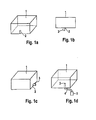
- Fig. 1 shows various ways to attach a liquid discharge device 3 according to the invention to a housing 1 of an energy storage device.
- Fig. 1 a is an attachment shown below the housing.
- Fig. 1b shows a side view.
- Fig. 1c shows a lateral attachment. This takes place in the lower area, so that water can flow into it.
- Fig. 1d shows a spatially separate attachment with a hose or pipe connection 4. It is ensured in each case by an inlet opening 2 in the outer wall of the liquid discharge device that liquid from the energy storage device 1 can penetrate into the liquid discharge device.
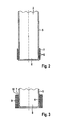
- FIG Fig. 2 An exemplary schematic liquid discharge device 3 is shown in FIG Fig. 2
- the liquid discharge device has lateral outer walls 5, which have outlet openings 6 at least in partial regions. Through this liquid can pass from an energy storage device, which has entered the interior of the liquid discharge device, to the liquid-absorbing device 7, which is arranged laterally on the bottom 8 of the liquid discharge device.
- the liquid-absorbing device 7 is shown schematically as a layer, which consists for example of a nonwoven fabric.
- Fig. 3 shows a remplisstechniksabbowvorrichfung with the features of Fig. 2 , wherein in addition a porous protective layer 9 is applied to the liquid-absorbing device 7, which is spatially separated by spacers 10 from this.
- the liquid-absorbing device 7 is formed as a layer.
- the liquid-absorbing layer conducts the liquid from the inside to the outside, while the porous protective layer 9 allows the escape of water vapor, but prevents the ingress of liquids and also develops a mechanical protective effect.
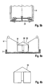
- a liquid discharge device 3 As in Fig. 4 is shown by way of example, a liquid discharge device 3 according to Fig. 2 or Fig. 3 stabilized by an additional outer protection 11, 12 and against the effects of mechanical forces and against contamination and splashing with liquids, etc, are protected.
- Fig. 4a is the external protection schematically as tube 11 and in Fig. 4b as a cylindrical cap (12) containing holes (13) in the outer protection shown.
- FIG. 5 shows a liquid discharge device with outer walls 5, on the underside of a pressure relief valve 20, 21 is mounted.
- Fig. 5a shows an embodiment as a lid 20 and Fig. 5b as a magnetic valve 21.
- FIG. 6 shows a liquid discharge device according to the invention with liquid-absorbing device 7, here formed as a layer, and outer walls 5.
- the check valve comprises according to Fig. 6a a sealing element, which is designed as a float 36, and a passage for liquid 33, such as condensed water.
- Fig. 6b shows a side view of the cylindrical float 36 and Fig. 6c a view with coaxial channels 32, which allow the outflow of the liquid, such as the condensate, in the open state and are closed when closed.
- the float 36 may consist of a thermoplastic, an elastomer or thermoplastic elastomer or have local seals made of these materials. It may preferably also be spherical. Alternatively or in addition to this, the point of contact of the projections 31 with the float 36 may also have a circumferential seal. Under certain circumstances, it may be sufficient to design the projections 31 from a flexible structure, for example a thermoplastic film, which acts on the pressure of the Floating seal. It is also conceivable that the float 36 with a spring or due to its low specific weight in the normal state is already slightly pressed against the counter surface and only by additional weight of action of pending liquid is moved downwards and thus opens. Such an arrangement is advantageous, for example, when there is a high risk of externally pending water. The float is then "closed" in the normal state.
- FIG. 7 shows a liquid discharge device according to the invention with liquid-absorbing device 7, porous layer 9, outer walls 6 and outlet openings 6.
- the liquid is discharged as a vapor through the porous layer 9 in the environment.
- a check valve comprises a membrane 40 which can be latched and fastened with sealing nipples 41 in openings for receiving the sealing nipples 42 of the housing.
- On the membrane 40 a sealing element 30 is attached.
- the membrane 40 has cavities for liquid transfer 43, for example in the form of pores, and is thereby liquid-permeable.
- the membrane Upon penetration of liquid from the outside and accumulation in the cavity 35, the membrane acts as a float with the sealing element and closes by movement up the passage for liquid 33.
- discharging the liquid is the lowering of the membrane 40 and the re-opening of the passage 33, so that again liquid, such as condensation, from the energy storage device can get into the liquid discharge device.
- FIG. 8a shows a check valve with a membrane 40, a sealing element 30 and a passage for liquid 33, such as condensation.
- FIG. 8b shows an alternative arrangement with a sealing ring 34 on a membrane 40th
- FIG. 9a shows an alternative arrangement with membrane 40 without additional sealing element.
- the membrane itself seals the passage 33 from.
- FIG. 9b shows an alternative arrangement with diaphragm 40, sealing member 30 and a spring 45 for bias. Such a spring may cause the membrane 40 to move more easily back to the starting position.
- FIG. 10 shows a check valve with sealing element 30 and an additional float 36 which is connected via a connecting element 37 with the sealing element 30.
- Fig. 11 schematically shows a inertia-controlled valve 46, which is closed when the motor vehicle is stationary and which briefly opens during a movement of the energy storage device by Verzögem the motor vehicle to admit liquid, such as condensation, in the liquid discharge device. It shows Fig. 11 the open state.
- the passage for liquid 33 is opened by the movement of the movable mass elements 47 with attached walls 48, while at rest, the closing takes place via the spring 45.
- Fig. 12a schematically shows a laminate of a membrane 40, which is part of a check valve, with a liquid-absorbing device 7, which is formed as a layer, in particular of nonwoven fabric.
- Fig. 12b shows a corresponding laminate, which additionally has a porous protective layer 9.
- the check valve is designed to close a passage for liquid positioned in front of the liquid-absorbing device.
- the non-return valve can also close a passage for liquid 33, which is connected downstream of the liquid-absorbing device 7 and optionally also the porous protective layer 9. With such a downstream check valve, the evaporation of the liquid from the liquid discharge device can be prevented.
- Such an arrangement has the advantage that the penetration of the liquid from the outside into the liquid-absorbing device 7 can be prevented.
- the liquid discharge device may contain sensors which emit signals about the state of the liquid discharge device.
- Fig. 14 is a liquid discharge device having the features of Fig. 7 shown, which additionally comprises three sensors 50, 51 and 52.
- an overcharge sensor 50 indicates the accumulation of liquid within the check valve.
- a liquid sensor 51 indicates the accumulation of liquid after the check valve.
- the liquid sensor 51 can simultaneously detect liquid that has entered from the environment.
- a temperature sensor 52 may be used to detect icing.
- the signals can be detected and optionally measures are initiated, such as turning on a heater falls below a critical temperature or too high an amount of liquid water.
- Fig. 15 shows a liquid discharge device with a check valve, which has a sealing element 30.
- a rotary member 70 is positioned below the liquid-absorbing device 7, which is formed as a layer, which directs the exiting water vapor from the sosstechniksabbowvorraum.
- Fig. 16 shows a liquid discharge device with check valve of a sealing element and a membrane 40, wherein the sealing element closes a passage for liquid 33.
- the liquid-absorbing device 7, here formed as a layer, and the porous protective layer 9 are arranged vertically. Such an arrangement allows a different kinetics in the discharge of the liquid and an efficient absorption of small amounts of liquid due to the accumulation in the soil area.
- FIG. 17 1 shows an energy storage device 1 with a liquid discharge device 3 attached thereto.
- the energy storage device 1 may be a battery that is positioned in a motor vehicle that generates traveling wind in the direction of the arrow 60.
- the discharge of the liquid can be improved when the liquid discharge device 3 is mounted at a position where the running wind is strong ( Fig. 17a ), or is specifically deflected, for example according to Fig. 17b with a backward vortex 61, or according to Fig. 17c with a nozzle 62, which is for example a Laval nozzle.
- a nozzle 62 which is for example a Laval nozzle.
- the devices and uses of the invention solve the problems underlying the invention.
- the liquid discharge devices allow the simple and efficient removal of condensation and other liquids from the inside of a battery or other energy storage device.
- the removal can be purely mechanical and continuous.
- nonwovens are particularly suitable, which deliver within 15 minutes the highest possible amount of water (as in Example 7).
- Such nonwoven fabrics are particularly efficient in transporting relatively large quantities of water from a liquid discharge device into the environment.
- Table 1 ⁇ / u>: Nonwovens and Results Example fleece Dry weight [g] Wet weight [g] Water tax [g] Water tax [%] 1 ST 170 FC BA 650325/04 0.45 1.09 0.52 0.81 2 ST 170 FC BA 493538/01 0.54 1.28 0.57 0.77 3 ST 171 FC blue BA650519 / 02 0.60 1.50 0.61 0.68 4 ST 3270 BP 650338/01 3.00 4.55 0.48 0.31 5 EVO 60 FC 0.40 0.82 0,3E 0.86 6 EVO 130 0.84 3.08 0.56 0.25 7 FS 2190 0.31 1.07 0.67 0.88 8th cooltexx 1.07 6.00 0.20 0.04 9 FFA2037 1.17 2.94 0.26 0.15
Landscapes
- Engineering & Computer Science (AREA)
- Power Engineering (AREA)
- Mechanical Engineering (AREA)
- Chemical Kinetics & Catalysis (AREA)
- Electrochemistry (AREA)
- General Chemical & Material Sciences (AREA)
- Chemical & Material Sciences (AREA)
- Transportation (AREA)
- Physics & Mathematics (AREA)
- Life Sciences & Earth Sciences (AREA)
- Sustainable Development (AREA)
- Sustainable Energy (AREA)
- Manufacturing & Machinery (AREA)
- Electromagnetism (AREA)
- Thermal Sciences (AREA)
- Fluid Mechanics (AREA)
- General Physics & Mathematics (AREA)
- Separation Using Semi-Permeable Membranes (AREA)
Abstract
Description
Die vorliegende Erfindung betrifft Vorrichtungen zur Entfernung von Flüssigkeit aus einer Energiespeichervorrichtung, sowie Energiespeichervorrichtungen, die solche Vorrichtungen umfassen und Verwendungen der Vorrichtungen.The present invention relates to apparatus for removing liquid from an energy storage device, and to energy storage devices comprising such apparatus and uses of the apparatus.
Speicher für elektrische und elektrochemische Energie, wie Batterien und Kondensatoren, enthalten abgeschlossene Zellen, die in einem Gehäuse platziert sind. Das äußere Gehäuse dient unter anderem zum Schutz der Zellen vor mechanischen Beeinträchtigungen, vor Verunreinigungen und vor dem Eindringen von Flüssigkeiten aus der Umgebung. Die Zellen füllen in der Regel das Gehäuse nicht vollständig aus, so dass ein nicht genutztes Totvolumen verbleibt. Dieses entsteht beispielsweise durch Einsatz runder Zellen in ein eckiges Gehäuse oder bei der Integration elektronischer Komponenten. Üblicherweise weisen Batterien mit einem Volumen von 5 bis über 200 l ein Totvolumen von etwa 5 bis 50% auf.Electric and electrochemical energy storage, such as batteries and capacitors, contain sealed cells that are placed in a housing. Among other things, the outer casing serves to protect the cells from mechanical damage, from contamination and from the ingress of liquids from the environment. As a rule, the cells do not completely fill the housing so that an unused dead volume remains. This arises, for example, by using round cells in a square housing or in the integration of electronic components. Typically, batteries having a volume of 5 to over 200 l have a dead volume of about 5 to 50%.
Bei solchen Energiespeichern tritt das Problem auf, dass sich bei Betrieb über längere Zeiträume Flüssigkeit in dem Gehäuse ansammelt. Die Flüssigkeit ist häufig Kondensat von Feuchtigkeit aus der Umgebung, es kann sich jedoch, zumindest anteilig, auch um eingedrungene Flüssigkeit beispielsweise bei Beschädigung des Gehäuses, bei Beschädigung des Kühlkreislaufes oder um ausgetretene Flüssigkeit aus den Zellen handeln. Die Bildung von Kondensat wird durch Schwankungen von Druck und Temperatur begünstigt, da dann die Batterie, um einen Druckausgleich gewährleisten zu können, "atmen" muss. Neben atmosphärischen Temperatur- und Druckschwankungen können solche Schwankungen durch Höhenunterschiede, beispielsweise bei Berg- und Talfahrten oder beim Fliegen, oder bei Ein- und Ausfahrten im Tunnel verursacht sein. Pro Jahr sammeln sich in einer Energiespeichervorrichtung je nach Größe typischerweise 100 bis 300 ml Kondensat an. Bei einer 100-l-Energiespeichervorrichtung, die täglich signifikanten Unterschieden der Temperatur und der Luftfeuchtigkeit ausgesetzt ist, kann das jährlich akkumulierte Kondensat auch deutlich über 1000 ml umfassen.In such energy storage, the problem arises that liquid accumulates in the housing during operation for longer periods of time. The liquid is often condensate of moisture from the environment, but it may act at least proportionally, even to penetrate liquid, for example, in case of damage to the housing, in case of damage to the cooling circuit or leaking liquid from the cells. The formation of condensate is favored by variations in pressure and temperature, because then the battery to be able to ensure pressure equalization, must "breathe". In addition to atmospheric temperature and pressure fluctuations, such fluctuations may be caused by differences in altitude, for example when driving up and down or when flying, or when entering and leaving the tunnel. Depending on the size, typically 100 to 300 ml of condensate accumulates in an energy storage device per year. For a 100-liter energy storage device that is exposed daily to significant differences in temperature and humidity, the annual accumulated condensate may well exceed 1000 ml.
Die Ansammlung von Flüssigkeiten In Energiespelchervorrichtungen kann zu Beeinträchtigungen der Leistung und im Extremfall zum Ausfall führen. Beispielsweise können Kriechströme oder Kurzschlüsse entstehen, wenn Kondensat in Kontakt mit stromführenden Teilen gelangt. Die Flüssigkeit kann auch die Korrosion von metallischen Komponenten bewirken, insbesondere wenn saure Gase, wie HCl oder Schwefeloxide, aus der Umgebungsluft durch das Kondensat ins Batterie-Innere gelangen.The accumulation of liquids In energy poller devices can lead to impairments of performance and in extreme cases to failure. For example, creepage currents or short circuits can occur when condensate comes in contact with live parts. The liquid can also cause the corrosion of metallic components, especially when sour gases, such as HCl or sulfur oxides, from the ambient air through the condensate into the battery interior.
Im Stand der Technik werden verschiedene Maßnahmen vorgeschlagen, um solche Flüssigkeiten aus dem Gehäuse von Energiespeichervorrichtungen zu entfernen. So wird durch den Einsatz von "atmungsaktiven Komponenten", wie beispielsweise dampfdurchlässige Werkstoffe der Markenbezeichnung Goretex, der Gasaustausch mit der Umgebung und damit die Abgabe von Wasserdampf unterstützt. Alternativ wird versucht, das Kondensat in dem Gehäuse durch Trockenmittel oder Superabsorber dauerhaft zu binden. Durch diese Maßnahmen werden die oben beschriebenen Probleme jedoch nicht vollständig gelöst. Es besteht jeweils die Gefahr, dass sich vor allem nach längerer Anwendung und in Gegenwart größerer Flüssigkeitsmengen das Trockenmittel oder die atmungsaktive Komponente mit Wasser füllt und überschüssiges Wasser nicht mehr abgeführt werden kann. Außerdem quellen Trockenmittel und Superabsorber bei der Benutzung, was wiederum zu Kurzschlüssen oder Kriechströmen führen kann und eine aufwändige Entfernung in regelmäßigen Abständen erfordert. Aufgequollene Superabsorber können innerhalb der Energiespeichervorrichtung leitfähige Brücken bilden oder mechanische Kräfte auf Kabel oder andere Bauteile in der Energiespeichervorrichtung ausüben. Bei Trockenmitteln besteht auch die Gefahr, dass korrosive oder elektrisch leitfähige Komponenten, wie Calciumchlorid oder Phosphorsäure, freigesetzt werden.Various measures are proposed in the prior art to remove such liquids from the housing of energy storage devices. Thus, the use of "breathable components", such as vapor-permeable materials of the brand name Goretex, supports the gas exchange with the environment and thus the emission of water vapor. Alternatively, it is attempted to permanently bind the condensate in the housing by desiccant or superabsorber. However, these measures do not completely solve the problems described above. There is always the danger that, especially after prolonged use and in the presence of larger amounts of liquid, the desiccant or the breathable component fills with water and excess water does not more can be dissipated. In addition, desiccants and superabsorbents swell during use, which in turn can lead to short circuits or creepage currents and requires time-consuming removal at regular intervals. Swollen superabsorbents may form conductive bridges within the energy storage device or exert mechanical forces on cables or other components in the energy storage device. With desiccants there is also the danger that corrosive or electrically conductive components, such as calcium chloride or phosphoric acid, are released.
Im Stand der Technik wird auch versucht, Kondenswasser mit Hilfe zusätzlicher elektrischer Komponenten gezielt abzuleiten. Beispielsweise kann ein Sensor in einem Gehäuse signalisieren, dass ein Magnetventil gezielt zu öffnen ist oder dass eine Pumpe aktiviert wird, die das Kondenswasser abführt. Problematisch ist dabei, dass solche Lösungen technisch relativ aufwändig und störanfällig sind. Außerdem verbrauchen sie Energie, was bei vielen Anwendungen, beispielsweise Batterien oder Brennstoffzellen von Elektrofahrzeugen mit geringer Reichweite, grundsätzlich nicht wünschenswert Ist. Nachteilig ist auch, dass bei solchen Lösungsansätzen das Kondenswasser nicht kontinuierlich abgeführt wird, sondem erst nach Überschreiten eines definierten Schwellenwertes. Dies führt dazu, dass ein gewisser Wassergehalt in dem Gehäuse toleriert wird, was jedoch bereits zu den oben beschriebenen Problemen wie Korrosion führen kann.The prior art also attempts to selectively divert condensation with the help of additional electrical components. For example, a sensor in a housing signal that a solenoid valve is to open targeted or that a pump is activated, which dissipates the condensation. The problem is that such solutions are technically relatively complex and prone to failure. In addition, they consume energy, which is not desirable in many applications, such as batteries or fuel cells of low-range electric vehicles. Another disadvantage is that the condensate is not removed continuously in such solutions, but only after exceeding a defined threshold. As a result, some water content in the housing is tolerated, but this can already lead to the problems described above, such as corrosion.
Der Erfindung liegt die Aufgabe zugrunde, Vorrichtungen und Verwendungen bereitzustellen, welche die oben beschriebenen Nachteile überwinden. Es soll eine möglichst einfache und effiziente Vorrichtung bereitgestellt werden, um Kondensat und sonstige Flüssigkeiten aus dem Inneren von Energiespeichervorrichtungen und ähnlichen Vorrichtungen zum Speichern von Energie zu entfernen. Die Vorrichtung selbst soll in ihrer Grundfunktion rein mechanisch ohne Nutzung elektrischer Energie arbeiten. Sie soll auf einfache Weise anwendbar und einsetzbar sein und möglichst wenig Wartungsaufwand erfordern. Die Entfernung von Kondensat und sonstigen Flüssigkeiten soll bevorzugt kontinuierlich erfolgen und nicht lediglich zu definierten Zeit- oder Kontrollpunkten. Die Vorrichtung soll unter verschiedenen Bedingungen einsetzbar sein und beispielsweise in der Lage sein, sowohl geringe als auch große Flüssigkeitsmengen zu entfemen.The invention has for its object to provide devices and uses which overcome the disadvantages described above. It is a simple and efficient device should be provided to remove condensate and other liquids from the inside of energy storage devices and similar devices for storing energy. The device itself should work in its basic function purely mechanically without the use of electrical energy. It should be applicable and usable in a simple manner and require as little maintenance as possible. The distance condensate and other liquids should preferably be continuous and not only at defined time or control points. The device should be usable under various conditions and, for example, be able to remove both small and large quantities of liquid.
Die vorliegende Erfindung löst die zuvor genannte Aufgabe durch Vorrichtungen und Verwendungen gemäß den Patentansprüchen. Weitere bevorzugte Ausführungsformen werden in der Beschreibung offenbart.The present invention achieves the above object by means of devices and uses according to the claims. Further preferred embodiments are disclosed in the description.
Gegenstand der Erfindung ist eine Flüssigkeitsabfuhrvorrichtung, insbesondere zur Entfernung von Flüssigkeit aus einer Energiespeichervorrichtung, wobei die Flüssigkeitsabfuhrvorrichtung mit der Energiespeichervorrichtung verbindbar ist, wobei die Flüssigkeitsabfuhrvorrichtung mindestens eine Einlassöffnung aufweist, durch die Flüssigkeit aus der Energiespeichervorrichtung in die Flüssigkeitsabfuhrvorrichtung gelangen kann, wobei die Flüssigkeitsabfuhrvorrichtung eine flüssigkeitsabsorbierende Einrichtung enthält, die Flüssigkeit an die Umgebung abgeben kann.The invention relates to a liquid discharge device, in particular for removing liquid from an energy storage device, wherein the liquid discharge device is connectable to the energy storage device, wherein the liquid discharge device has at least one inlet opening, can pass through the liquid from the energy storage device in the liquid discharge device, wherein the liquid discharge device is a liquid-absorbing Contains device that can deliver liquid to the environment.
Die Flüssigkeitsabfuhrvorrichtung dient bevorzugt zur Entfernung von Flüssigkeit aus einer Energiespeichervorrichtung. Erfindungsgemäß dient die Energiespeichervorrichtung insbesondere zur Speicherung von elektrischer oder elektrochemischer Energie. Erfindungsgemäße Energiespeichervorrichtungen schließen Vorrichtungen zur Erzeugung und Umwandlung von elektrischer oder elektrochemischer Energie ein, wie zum Beispiel Brennstoffzellen. Geeignete Energiespeichervorrichtungen sind insbesondere solche, die Zellen zur Speicherung, Umwandlung und/oder Erzeugung von elektrischer und/oder elektrochemischer Energie in einem Gehäuse enthalten. Bevorzugt ist die Energiespeichervorrichtung ausgewählt aus Batterien, Kondensatoren, Superkondensatoren, Akkumulatoren und Brennstoffzellen.The liquid discharge device preferably serves to remove liquid from an energy storage device. According to the invention, the energy storage device is used in particular for the storage of electrical or electrochemical energy. Energy storage devices according to the invention include devices for generating and converting electrical or electrochemical energy, such as fuel cells. Suitable energy storage devices are, in particular, those which contain cells for storing, converting and / or generating electrical and / or electrochemical energy in a housing. Preferably, the energy storage device is selected from batteries, capacitors, supercapacitors, accumulators and fuel cells.
Dabei dient die erfindungsgemäße Flüssigkeitsabfuhrvorrichtung zur Entfernung von Flüssigkeit aus dem Gehäuse der Energiespeichervorrichtung. Die zu entfernende Flüssigkeit ist insbesondere Kondenswasser (Kondensat), kann jedoch auch von außen eingedrungene Flüssigkeit oder Leckage-Flüssigkeit aus einem Kühlkreislauf oder einer Energiespeicherzelle sein, oder ein Gemisch solcher Flüssigkeiten. Die Flüssigkeit ist bevorzugt Wasser oder eine wässrige Lösung. Sie kann jedoch, beispielsweise im Falle von Elektrolyten oder Kühlflüssigkeiten, auch ein organisches Lösungsmittel sein oder zumindest enthalten. Die Flüssigkeit kann gelöste Bestandteile, wie Salze oder Gase, enthalten.In this case, the liquid discharge device according to the invention serves to remove liquid from the housing of the energy storage device. The liquid to be removed is, in particular, condensation water (condensate), but may also be liquid or leakage fluid which has penetrated from the outside from a cooling circuit or an energy storage cell, or a mixture of such liquids. The liquid is preferably water or an aqueous solution. However, it may, for example in the case of electrolytes or coolants, also be or at least contain an organic solvent. The liquid may contain dissolved components, such as salts or gases.
Die Flüssigkeit sammelt sich zunächst im Inneren der Energiespeichervorrichtung an. Bevorzugt wird die erfindungsgemäße Flüssigkeitsabfuhrvorrichtung mit der Energiespeichervorrichtung so verbunden, dass die Flüssigkeit mechanisch durch die Einlassöffnung in die Flüssigkeitsabfuhrvorrichtung gelangt. Dies kann auf einfache Weise unter Ausnützung der Schwerkraft gewährleistet werden, wenn die Flüssigkeitsabfuhrvorrichtung auf der Unterseite der Energiespeichervorrichtung angebracht wird, bevorzugt am tiefsten Punkt der Energiespeichervorrichtung. Die Flüssigkeitsabfuhrvorrichtung kann jedoch auch seitlich oder an beliebigen anderen Positionen des Gehäuses der Energiespeichervorrichtung angebracht werden. Bei Verwendung in Fahrzeugen können auch Positionen gewählt werden, bei denen die sich sammelnde Flüssigkeit durch typische Fahrbewegungen hintransportiert wird. So kann die Flüssigkeitsabfuhrvorrichtung hinter oder vor der Energiespeichervorrichtung positioniert werden. Die Flüssigkeit wird dann beispielsweise durch Beschleunigung oder Verzögerung der Flüssigkeitsabfuhrvorrichtung zugeführt.The liquid initially accumulates in the interior of the energy storage device. Preferably, the liquid discharge device according to the invention is connected to the energy storage device so that the liquid passes mechanically through the inlet opening into the liquid discharge device. This can be easily ensured by utilizing gravity when the liquid discharge device is mounted on the underside of the energy storage device, preferably at the lowest point of the energy storage device. However, the liquid discharge device may also be mounted laterally or at any other position of the housing of the energy storage device. When used in vehicles, positions can also be selected in which the collecting liquid is transported by typical driving movements. Thus, the liquid discharge device can be positioned behind or in front of the energy storage device. The liquid is then supplied, for example, by acceleration or deceleration of the liquid discharge device.
Die Verbindung der Energiespeichervorrichtung mit der Flüssigkeitsabfuhrvorrichtung weist eine Einlassöffnung auf, durch welche die Flüssigkeit aus der Energiespeichervorrichtung in die Flüssigkeitsabfuhrvorrichtung gelangt. In der erfindungsgemäßen Flüssigkeitsabfuhrvorrichtung wird die Flüssigkeit bei Kontakt mit einer flüssigkeitsabsorbierenden Einrichtung von dieser aufgenommen. Die flüssigkeitsabsorbierende Einrichtung gibt die Flüssigkeit an die Umgebung ("nach außen") ab. Bevorzugt erfolgt die Flüssigkeitsabgabe durch Verdunstung. Dann wird die Flüssigkeit nicht in flüssiger Form, sondern als Dampf an die Umgebung abgegeben.The connection of the energy storage device to the liquid discharge device has an inlet opening through which the liquid passes from the energy storage device into the liquid discharge device. In the liquid discharge device according to the invention, the liquid is taken up on contact with a liquid-absorbing device thereof. The liquid-absorbing device indicates the liquid the environment ("outwards"). Preferably, the liquid is dispensed by evaporation. Then the liquid is not released in liquid form, but as a vapor to the environment.
Die erfindungsgemäße Flüssigkeitsabfuhrvorrichtung weist ein äußeres Gehäuse mit Außenwänden auf. Geeignet ist beispielsweise ein rohrförmiges oder zylinderförmiges Gehäuse. Das Gehäuse kann direkt formschlüssig mit der Energiespeichervorrichtung verbunden werden oder auch indirekt, beispielsweise über eine Schlauch- oder Rohrverbindung. Durch mindestens eine Auslassöffnung wird gewährleistet, dass Flüssigkeit durch die flüssigkeitsabsorbierende Einrichtung in die Umgebung, das heißt aus der Vorrichtung hinaus, transferiert werden kann.The liquid discharge device according to the invention has an outer housing with outer walls. For example, a tubular or cylindrical housing is suitable. The housing can be directly positively connected to the energy storage device or indirectly, for example via a hose or pipe connection. By means of at least one outlet opening it is ensured that liquid can be transferred through the liquid-absorbing device into the environment, that is to say out of the device.
In einer bevorzugten Ausführungsform der Erfindung ist die flüssigkeitsabsorbierende Einrichtung ein Vliesstoff, ein Gewebe, eine Netz, ein Faserbündel, wie eine Schnur, ein Hohlfaserbündel oder ein Seil, ein Papier, eine flüssigkeitsdurchlässige Membran und/oder eine Partikelschüttung. Die Membran ist bevorzugt löchrig oder offenporig, insbesondere mikroporös. Die flüssigkeitsabsorbierende Einrichtung dient gleichzeitig zur Aufnahme der Flüssigkeit aus der Energiespeichervorrichtung und zur Abgabe der Flüssigkeit an die Umgebung, insbesondere durch Verdunsten.In a preferred embodiment of the invention, the liquid-absorbing device is a nonwoven fabric, a woven fabric, a net, a fiber bundle, such as a string, a hollow fiber bundle or a rope, a paper, a liquid-permeable membrane and / or a particle bed. The membrane is preferably holy or porous, in particular microporous. The liquid-absorbing device serves at the same time for receiving the liquid from the energy storage device and for delivering the liquid to the environment, in particular by evaporation.
Besonders bevorzugt ist die flüssigkeitsabsorbierende Einrichtung eine Schicht. Durch eine Schichtstruktur kann wegen der großen Oberfläche auf beiden Seiten eine effiziente Aufnahme sowie Abgabe der Flüssigkeit an die Umgebung erreicht werden. Die flüssigkeitsabsorbierende Einrichtung und/oder Schicht ist bevorzugt hydrophil, so dass eine effiziente Wasseraufnahme und Wasserabgabe erreicht wird. Dabei ist es bevorzugt, dass die Geschwindigkeit der Wasseraufnahme und -abgabe hoch ist. Dagegen ist eine hohe Wasseraufnahmekapazität weniger bedeutsam, da die Einrichtung im Wesentlichen nicht als Flüssigkeitsspeicher, sondern zur Weiterleitung bzw. Verdunstung der Flüssigkeit dienen soll. Auf diese Weise kann eine Ansammlung großer Flüssigkeitsmengen mit den damit verbundenen Problemen, wie Quellung und Gewichtszunahme, vermieden werden.Particularly preferably, the liquid-absorbing device is a layer. Due to the layered structure, due to the large surface area on both sides, an efficient uptake and discharge of the liquid to the environment can be achieved. The liquid-absorbing device and / or layer is preferably hydrophilic, so that an efficient water absorption and discharge is achieved. It is preferable that the rate of water absorption and discharge is high. In contrast, a high water absorption capacity is less significant, since the device is essentially not intended to serve as a liquid storage, but to forward or evaporate the liquid. In this way, an accumulation of large amounts of fluid with the associated problems, such as swelling and weight gain, can be avoided.
In einer bevorzugten Ausführungsform der Erfindung weist die wasserableitende Schicht eine Dicke von 0,05 bis 10 mm, bevorzugt zwischen 0,1 bis 5 mm oder zwischen 0,2 bis 2 mm auf.In a preferred embodiment of the invention, the water-draining layer has a thickness of 0.05 to 10 mm, preferably between 0.1 to 5 mm or between 0.2 to 2 mm.
Die flüssigkeitsabsorbierende Schicht wird bevorzugt parallel zu einer Außenwand der Flüssigkeitsabfuhrvorrichtung angeordnet. Bevorzugt enthält die Außenwand mindestens eine Auslassöffnung zur Abgabe der Flüssigkeit an die Umgebung. Durch diese Maßnahmen wird eine effiziente Flüssigkeitsabfuhr erreicht.The liquid-absorbing layer is preferably arranged parallel to an outer wall of the liquid discharge device. Preferably, the outer wall includes at least one outlet opening for discharging the liquid to the environment. By these measures, an efficient liquid removal is achieved.
In einer bevorzugten Ausführungsform ist die flüssigkeitsabsorbierende Schicht ein Vliesstoff. Es wurde festgestellt, dass Vliesstoffe in besonderem Maße eine effiziente Flüssigkeitsaufnahme und -abgabe bewirken können. In einer bevorzugten Ausführungsform besteht das Vlies aus anorganischen Fasem. Dabei ist vorteilhaft, dass anorganische Fasem weitgehend inert gegen Verrottung oder Zersetzung sind, insbesondere bei erhöhten Temperaturen und in Gegenwart von Feuchtigkeit. Anorganische Fasem können z.B. aus Graphit, Metallen oder auch mineralischen Komponenten bestehen.In a preferred embodiment, the liquid-absorbing layer is a nonwoven fabric. It has been found that nonwovens can, in particular, bring about efficient liquid absorption and release. In a preferred embodiment, the nonwoven fabric consists of inorganic fibers. It is advantageous that inorganic fibers are largely inert to rotting or decomposition, especially at elevated temperatures and in the presence of moisture. Inorganic fibers may e.g. consist of graphite, metals or mineral components.
In einer weiteren bevorzugten Ausführungsform besteht das Vlies aus Fasem oder Filamenten aus organischen Polymeren. Bevorzugt sind Faserstärken von weniger als 15 µm, da die dadurch entstehende große Oberfläche des Vliesstoffes zu einer effizienten Flüssigkeitsaufnahme führt. Die organischen Polymere können aus üblichen Werkstoffen bestehen, beispielsweise Polyamid, Polyester (PES) oder auch aus Mischungen, z.B. aus Polyamid und Polyester. Geeignet sind auch hydrophilierte Polyolefine, beispielsweise solche mit einer UV-induzierten Pfropfung mit ungesättigten organischen Substanzen, wie Acrylsäure oder Maleinsäureanhydrid. Geeignet sind auch Vliese mit einer dauerhaften Beschichtung von hydrophilen organischen oder anorganischen Partikeln, wie SiO2, Al2O3 oder TiO2.In a further preferred embodiment, the fleece consists of fibers or filaments of organic polymers. Preferably, fiber thicknesses of less than 15 microns, since the resulting large surface of the nonwoven fabric leads to an efficient fluid absorption. The organic polymers may consist of conventional materials, for example polyamide, polyester (PES) or else mixtures, for example of polyamide and polyester. Also suitable are hydrophilicized polyolefins, for example those with a UV-induced grafting with unsaturated organic substances, such as acrylic acid or maleic anhydride. Also suitable are nonwovens with a permanent coating of hydrophilic organic or inorganic particles, such as SiO 2 , Al 2 O 3 or TiO 2 .
Die flüssigkeitsabsorbierende Einrichtung kann auch aus Bündeln aus Hohlfasem oder Fasersträngen, wie Schnüren oder Seilen, bestehen.The liquid-absorbing device can also consist of bundles of hollow fibers or fiber strands, such as cords or ropes.
Die flüssigkeitsabsorbierende Einrichtung kann auch eine Schüttung hydrophiler Partikel sein. Bevorzugt sind anorganische Partikel, beispielsweise SiO2, Al2O3, TiO2 oder Kohlepartikel, oder organische Partikel, wie Superabsorber (SAP)-Partikel. Auch Partikel biologischen Ursprungs, wie Holzstreu, können eingesetzt werden, wobei in diesem Falle deren geringe Verrottungs-Stabilität zu berücksichtigen ist. Die Schüttung kann zwischen zwei porösen Membranen oder Vliesstoffen oder sonstigen Trennschichten angeordnet sein.The liquid-absorbing device may also be a bed of hydrophilic particles. Preference is given to inorganic particles, for example SiO 2 , Al 2 O 3 , TiO 2 or carbon particles, or organic particles, such as superabsorbent (SAP) particles. Also particles of biological origin, such as wood litter, can be used, in which case their low rot-resistance is taken into account. The bed can be arranged between two porous membranes or nonwovens or other separating layers.
Erfindungsgemäß können auch beliebige Kombinationen der genannten flüssigkeitsabsorbierenden Einrichtungen eingesetzt werden. Beispielsweise können Laminate aus verschiedenen Schichten, wie Vliesen und Partikelschüttungen, eingesetzt werden, oder Materialien können innerhalb einer Schicht vermischt werden.According to the invention, it is also possible to use any desired combinations of said liquid-absorbing devices. For example, laminates of various layers, such as nonwovens and particle beds, can be used, or materials can be mixed within a layer.
In einer bevorzugten Ausführungsform der Erfindung weist die Flüssigkeitsabfuhrvorrichtung zusätzlich eine poröse Schutzschicht auf, die zwischen der flüssigkeitsabsorbierenden Einrichtung und der Umgebung angeordnet ist, wobei die poröse Schutzschicht wasserdampfdurchlässig und flüssigkeitsundurchlässig ist. Die poröse Schutzschicht ist also so angeordnet, dass durch sie Wasserdampf, der aus der flüssigkeitsabsorbierenden Einrichtung abgegeben wird, in die Umgebung gelangt.In a preferred embodiment of the invention, the liquid discharge device additionally comprises a porous protective layer disposed between the liquid-absorbing device and the environment, wherein the porous protective layer is permeable to water vapor and liquid-impermeable. The porous protective layer is thus arranged so that through it water vapor, which is discharged from the liquid-absorbing device, enters the environment.
In einer bevorzugten Ausführungsform der Erfindung ist die poröse Schutzschicht ein Vlies, ein Netz, ein Gewebe oder eine Membran. Dabei ist die Schutzschicht bevorzugt hydrophobiert und/oder oleophobiert. Diese poröse Schutzschicht schützt die flüssigkeitsabsorbierende Einrichtung und somit das Innere der Flüssigkeitsabfuhrvorrichtung davor, dass Flüssigkeit aus der Umgebung eindringt. Die poröse Schutzschicht soll insbesondere das Eindringen von Wasser, beispielsweise Spritzwasser beim Betrieb von Fahrzeugen, oder Ölen verhindern. Zusätzlich dient die Schutzschicht als Schutz vor Partikeln, Staub und gegebenenfalls mechanischen Beeinträchtigungen. Gegebenenfalls kann die Schutzschicht auch so ausgebildet sein, dass sie das Eindringen von korrosiven Gasen, wie Schwefeloxide oder Stickoxiden, verhindert.In a preferred embodiment of the invention, the porous protective layer is a fleece, a net, a woven fabric or a membrane. The protective layer is preferably hydrophobicized and / or oleophobed. This porous protective layer protects the liquid-absorbing device and thus the inside of the liquid discharge device from the penetration of liquid from the environment. The porous protective layer should in particular prevent the ingress of water, for example spray water during operation of vehicles, or oils. In addition, the protective layer serves as protection against particles, dust and possibly mechanical damage. Optionally, the protective layer may also be formed so as to prevent the penetration of corrosive gases, such as sulfur oxides or nitrogen oxides.
Materialien, die dampfdurchlässig und flüssigkeitsundurchlässig sind, sind grundsätzlich bekannt. Sie werden z.B. in Kleidungsapplikationen als "atmungsaktiv" bezeichnet. Solche Materiallen basieren im Allgemeinen auf Membranen ("Gore-Tex") oder aus Fasermaterialien, wie Vliesen, deren Oberflächen hydrophobiert sind, beispielsweise durch eine Überschichtung mit Fluorkohlenwasserstoffen, Silikonen oder Polyurethanen. In einer bevorzugten Ausführungsform ist die Beschichtung zugleich hydrophob und oleophob. In einer weiteren bevorzugten Ausführungsform werden atmungsaktive, hydrophobe Membranen, beispielsweise auf der Basis von PTFE (Polytetrafluorethylen) oder Polyolefinen eingesetzt. Je nach Platzierung der Flüssigkeitsabfuhrvorrichtung können an die Schutzschicht unterschiedliche Anforderungen gestellt werden. Kommt die Vorrichtung beispielsweise lediglich in Kontakt mit Spritzwasser, so können relativ offenporige Materialien eingesetzt werden. Wenn das Element darüber hinaus aber auch eine Watfähigkeit von z.B. von mehr als 500 mm Wassersäule aufweisen soll, so sollten die maximalen Poren der Vliesstoffe bzw. Membranen bei Werten von unterhalb 30 µm (bevorzugt unterhalb von 20 µm) liegen. Die Vliesstoffe oder Membranen können in einer weiteren Ausführungsform zusätzlich mit Heizelementen versehen werden.Materials which are vapor permeable and liquid impermeable are generally known. They are e.g. in clothing applications referred to as "breathable". Such materials are generally based on membranes ("Gore-Tex") or of fiber materials, such as nonwovens, the surfaces of which are rendered hydrophobic, for example by coating with fluorohydrocarbons, silicones or polyurethanes. In a preferred embodiment, the coating is at the same time hydrophobic and oleophobic. In a further preferred embodiment, breathable, hydrophobic membranes, for example based on PTFE (polytetrafluoroethylene) or polyolefins, are used. Depending on the placement of the liquid discharge device, different requirements can be placed on the protective layer. For example, if the device only comes into contact with spray water, then relatively open-pored materials can be used. In addition, if the element also has a wetting capability of e.g. should have more than 500 mm of water, the maximum pores of the nonwoven fabrics or membranes should be at values of below 30 microns (preferably below 20 microns). The nonwovens or membranes can be additionally provided with heating elements in a further embodiment.
Erfindungsgemäß kann eine flüssigkeitsabsorbierende Schicht flächig mit einer äußeren porösen Schutzschicht verbunden werden, so dass ein Laminat erhalten wird. Alternativ ist es bevorzugt, zwischen einer flüssigkeitsabsorbierenden Schicht und einer porösen Schutzschicht Abstandshalter ("Spacer") anzubringen. Dadurch entstehen definierte Hohlräume zwischen beiden Schichten. Durch solche Abstandshalter zwischen der hydrophilen inneren Schicht und der hydrophoben äußeren Schicht kann die Gefahr reduziert werden, dass Wasser aus der Umgebung von außen in die Flüssigkeitsabfuhrvorrichtung eindringt, da sich keine Filme bilden können, die das Wasser durch das hydrophile Vlies drücken. Bevorzugte Abstandshalter sind beispielsweise Netze, Gewebe oder Vliesstoffe, wobei als Vliesstoffe insbesondere solche mit größeren Poren bzw. dickeren Fasem geeignet sind.According to the invention, a liquid-absorbing layer can be bonded flat to an outer porous protective layer so that a laminate is obtained. Alternatively, it is preferred to attach spacers between a liquid-absorbing layer and a porous protective layer. This creates defined cavities between the two layers. Such spacers between the hydrophilic inner layer and the hydrophobic outer layer can reduce the risk that water from the outside penetrates into the liquid discharge device, since no films can form, which push the water through the hydrophilic nonwoven. Preferred spacers are, for example, nets, woven fabrics or nonwovens, nonwovens in particular those with larger pores or thicker fibers being suitable.
In einer bevorzugten Ausführungsform der Erfindung weist die Fiüssigkeitsabfuhrvorrichtung eine äußere Schutzhülle auf. Die äußere Schutzhülle dient zum Schutz der Flüssigkeitsabfuhrvorrichtung vor mechanischen Schäden, beispielsweise gegen Steinschlag am Unterboden eines Kraftfahrzeugs. Sie soll den Abtransport von Flüssigkeit aus der Flüssigkeitsabfuhrvorrichtung nicht beeinträchtigen und muss daher Löcher oder größere Poren aufweisen. Die äußere Schutzhülle kann beispielsweise die Form eines Rohres aufweisen. Im Übrigen kann sie jede beliebige Form aufweisen, die an das Gehäuse der Flüssigkeitsabfuhrvorrichtung angepasst ist. Die Schutzhülle kann beispielsweise aus gelöchertem Metall oder Kunststoff, wie Polyamid, TPE oder aus geeigneten Elastomeren bestehen. Es kann auch ein mit Stahlwolle gefülltes Lochblech eingesetzt werden. Dadurch kann eine Tiefenfilterung erfolgen und eine direkte Einwirkung von Wasser aus der Umgebung oder von Partikeln und Schäden durch Steinschlag verhindert werden. Eine solche äußere Schutzschicht verhindert auch die Verschmutzung der Flüssigkeitsabfuhrvorrichtung und der funktionalen hydrophilen oder hydrophoben wasserableitenden Schichten.In a preferred embodiment of the invention, the liquid discharge device has an outer protective cover. The outer protective cover serves to protect the liquid discharge device against mechanical damage, for example against stone chipping on the underbody of a motor vehicle. It should not affect the removal of liquid from the liquid discharge device and must therefore have holes or larger pores. The outer protective cover may for example have the shape of a tube. Incidentally, it may have any shape which is adapted to the housing of the liquid discharge device. The protective cover may for example consist of perforated metal or plastic, such as polyamide, TPE or suitable elastomers. It can also be used with a steel wool filled perforated plate. This can be used for depth filtration and to prevent the direct impact of water from the environment or of particles and damage caused by falling rocks. Such an outer protective layer also prevents contamination of the liquid discharge device and the functional hydrophilic or hydrophobic water-draining layers.
Die erfindungsgemäße Flüssigkeitsabfuhrvorrichtung bewirkt einen effektiven Flüssigkeitstransport aus der Energiespeichervorrichtung durch die flüssigkeitsabsorbierende Schicht der Flüssigkeitsabfuhrvorrichtung in die äußere Umgebung der Flüssigkeitsabfuhrvorrichtung. In einer bevorzugten Ausführungsform der Erfindung weist die Flüssigkeitsabfuhrvorrichtung ein Rückschlagventil auf, das den Flüssigkeitstransport aus der Energiespeichervorrichtung in die Umgebung unterbricht, wenn Flüssigkeit aus der Umgebung in die Flüssigkeitsabfuhrvorrichtung einzudringen droht Grundsätzlich Ist Jedes bekannte Rückschlagventil einsetzbar, das in Gegenwart von Flüssigkeit einen Durchlass für Flüssigkeit verschließt. Bevorzugt weist das Rückschlagventil ein Dichtelement auf, das das Eindringen von außen anstehender Flüssigkeit in die Energiespeichervorrichtung verhindert und die Vorrichtung so nachhaltig abdichtet.The liquid discharge device according to the invention effects an effective liquid transport from the energy storage device through the liquid-absorbing layer of the liquid discharge device into the outer environment of the liquid discharge device. In a preferred embodiment of the invention, the liquid discharge device has a check valve which interrupts the liquid transport from the energy storage device into the environment when liquid from the environment threatens to penetrate into the liquid discharge device. Basically, any known check valve can be used, which in the presence of liquid is a passage for liquid closes. Preferably, the check valve has a sealing element which prevents the penetration of externally applied liquid into the energy storage device and thus seals the device so effectively.
In einer bevorzugten Ausführungsform weist das Rückschlagventil einen Schwimmer auf. Bevorzugt ist das Dichtelement selbst als Schwimmer ausgebildet. Ein Schwimmer weist eine geringere Dichte als die Flüssigkeit, insbesondere als Wasser, auf und ist in Richtung des Durchlasses beweglich. Dabei wird der Schwimmer in einer ausreichenden Flüssigkeitsmenge wegen der geringeren Dichte angehoben. Da der Schwimmer oder das Dichtelement in den darüber liegenden Durchlass passen oder mit diesem formschlüssig abschließen, wird dieser durch den erhöhten Flüssigkeitsspiegel in die Öffnung gedrückt und schließt diese effektiv ab. Die Flüssigkeitsabfuhrvorrichtung kann dann so lange keine Flüssigkeit, wie Kondenswasser, mehr aufnehmen, bis die Flüssigkeit wieder über die flüssigkeitsabsorbierende Schicht aus der Flüssigkeitsabfuhrvorrichtung transportiert wurde. Der Schwimmer sollte eine Gesamtdichte von deutlich unterhalb 1 kg/l aufweisen. Er kann dafür z.B. aus spezifisch leichteren Vollmaterialien bestehen, z.B. polyolefinischen Kunststoffen oder Holz. Er kann aus hohl ausgestaltet sein, z.B. als Hohlkugel, oder auch Schaum- bzw. Wabenstrukturen beinhalten. Denkbar ist auch ein innerer Hohlraum, welcher ein Gas enthält, welches spezifisch leichter ist als Luft (z.B. Helium) oder ein Vakuum.In a preferred embodiment, the check valve on a float. Preferably, the sealing element itself is designed as a float. A float has a lower density than the liquid, especially as water, and is movable in the direction of the passage. The float is raised in a sufficient amount of liquid because of the lower density. Since the float or the sealing element in the overlying passage fit or close with this form-fitting, this is pressed by the increased liquid level in the opening and closes this effectively. The liquid discharge device can then no longer absorb any liquid, such as condensed water, until the liquid has been transported again via the liquid-absorbing layer out of the liquid discharge device. The float should have a total density of well below 1 kg / l. For example, it can consist of specifically lighter solid materials, eg polyolefinic plastics or wood. It may be made of hollow, for example as a hollow sphere, or also include foam or honeycomb structures. Also conceivable is an inner cavity which contains a gas which is specifically lighter than air (eg helium) or a vacuum.
In einer bevorzugten Ausführungsform der Erfindung sind das Dichtelement und/oder der Schwimmer zylindrisch, kugelförmig, kegelförmig oder ringförmig ausgebildet und/oder auf einer porösen bzw. definierte Löcher enthaltenden Membran angebracht. Ein zylindrisches oder kugelförmiges Dichtelement kann eine kreisförmige Öffnung effizient verschließen. Ein ringförmiges Dichtelement kann beispielsweise als Dichtring ausgebildet sein und eine Öffnung mit beliebiger Geometrie verschließen. Die Anbringung des Dichtelements auf einer flüssigkeitsdurchlässigen, insbesondere porösen bzw. Löcher enthaltende Membran erlaubt die gleichmäßige Anhebung des Dichtelements in Gegenwart von Flüssigkeit. Die Membran kann bei geringer Dichte und guter Beweglichkeit selbst als Schwimmer wirken oder zusammen mit einem Dichtelement einen Schwimmer bilden. Generell kann die Dichtfunktion durch Elastomere oder auch thermoplastische Elastomere, welche am beweglichen Teil angebracht sind, oder durch Elastomere oder auch thermoplastische Elastomere, welche am starren Teil angebracht sind, sichergestellt werden. Darüber hinaus ist auch denkbar, Elastomere oder auch thermoplastische Elastomere an beiden Teilen anzubringen.In a preferred embodiment of the invention, the sealing element and / or the float are cylindrical, spherical, conical or annular and / or mounted on a porous or defined holes containing membrane. A cylindrical or spherical sealing element can efficiently close a circular opening. An annular sealing element may for example be formed as a sealing ring and close an opening with any geometry. The attachment of the sealing element on a liquid-permeable, in particular porous or containing holes membrane allows the uniform lifting of the sealing element in the presence of liquid. The membrane can act as a float at low density and good mobility or form a float together with a sealing element. In general, the sealing function can be ensured by elastomers or thermoplastic elastomers, which are attached to the moving part, or by elastomers or thermoplastic elastomers, which are attached to the rigid part. In addition, it is also conceivable to attach elastomers or else thermoplastic elastomers to both parts.
Das Dichtelement kann auch als Schalter ausgebildet sein oder aus einem quellenden Elastomer bestehen. Bevorzugt ist die Abdichtung der Flüssigkeitsabfuhrvorrichtung durch das Rückschlagventil und insbesondere durch den Schwimmer reversibel, so dass nach Entfernung der Flüssigkeit wieder die Freigabe des Durchlasses erfolgt.The sealing element may also be designed as a switch or consist of a swelling elastomer. Preferably, the sealing of the liquid discharge device by the check valve and in particular by the float is reversible, so that after removal of the liquid again the release of the passage.
Die poröse Membran, an der das Dichtelement befestigt ist, kann mit weiteren Schichten der Flüssigkeitsabfuhrvorrichtung laminiert sein. In einer bevorzugten Ausführungsform der Erfindung umfasst die Flüssigkeitsabfuhrvorrichtung ein Laminat aus einer porösen Membran, einer flüssigkeitsabsorbierenden Einrichtung und gegebenenfalls einer porösen Schutzschicht. Die Verbindung der Schichten in der Flüssigkeitsabfuhrvorrichtung zu einem Laminat gewährleistet einen einfachen und platzsparenden Aufbau und einen einfachen Austausch bei Wartung oder Beschädigung.The porous membrane to which the sealing member is attached may be laminated with other layers of the liquid discharge device. In a preferred embodiment of the invention, the liquid discharge device comprises a laminate of a porous membrane, a liquid-absorbing device and optionally a porous protective layer. The connection of the layers in the liquid discharge device to a laminate ensures a simple and space-saving construction and a simple replacement during maintenance or damage.
In einer bevorzugten Ausführungsform der Erfindung weist die Flüssigkeitsabfuhrvorrichtung ein Sicherheitsventil auf, das sich bei Überschreitung des maximal zulässigen Überdrucks öffnet. Mit einem solchen Sicherheitsventil kann bei unzulässigem Überdruck gewährleistet werden, dass die Energiespeichervorrichtung und die Flüssigkeitsabfuhrvorrichtung nicht beschädigt werden. Auf diese Weise kann eine Fehlfunktion der Energiespeichervorrichtung ausgeglichen werden. Das Sicherheitsventil kann beispielsweise ein einfaches Überdruckelement sein, das bei erhöhtem Druck aus einer Halterung springt oder an einer Sollbruchstelle bricht. Ein erfindungsgemäßer Überdruckdeckel kann auch durch einen Permanentmagneten fixiert werden. Der Zeitpunkt der Ablösung kann über die Größe des Magneten und dessen Füllgrad eingestellt werden. Die metallische Gegenfläche ist dabei in die Dichtung integriert, so dass das Ventil auch in nicht magnetischen Energiespeichervorrichtungen einsetzbar ist. Das Überdruckventil kann auch aus einem Elastomer bestehen, das durch äußere Nippel gehalten wird und sich bei einem definierten Überdruck aus der Halterung löst.In a preferred embodiment of the invention, the liquid discharge device has a safety valve which opens when the maximum permissible overpressure is exceeded. With such a safety valve can be ensured at unacceptable pressure that the energy storage device and the liquid discharge device are not damaged. In this way, a malfunction of the energy storage device can be compensated. The safety valve may for example be a simple overpressure element that jumps from a holder at elevated pressure or breaks at a predetermined breaking point. An inventive overpressure cover can also be fixed by a permanent magnet. The time of detachment can be adjusted by the size of the magnet and its degree of filling. The metallic mating surface is integrated into the seal, so that the valve can also be used in non-magnetic energy storage devices. The pressure relief valve may also consist of an elastomer, which is held by outer nipples and dissolves at a defined pressure from the holder.
In einer bevorzugten Ausführungsform der Erfindung weist die Flüssigkeitsabfuhrvorrichtung mindestens einen Sensor auf. Bevorzugt werden Flüssigkeitssensoren und/oder Temperatursensoren eingesetzt. Beispielsweise kann ein Sensor die Akkumulation von Flüssigkeit in der Flüssigkeitsabfuhrvorrichtung oder die Aufnahme von Flüssigkeit durch die flüssigkeitsabsorbierende Schicht anzeigen. Auf diese Weise kann unerwünschtes Eindringen von Flüssigkeit in die Flüssigkeitsabfuhrvorrichtung oder unerwünschte Akkumulation von Flüssigkeit in der Flüssigkeitsabfuhrvorrichtung angezeigt werden. Mit einem Temperatursensor kann beispielsweise unerwünschtes Einfrieren der Flüssigkeitsabfuhrvorrichtung gemessen werden. Über eine Detektionseinrichtung können die Signale von den Sensoren ausgewertet werden und gegebenenfalls Maßnahmen eingeleitet werden, welche die erkannten Missstände beheben. Beispielsweise kann der Temperatursensor das Einschalten eines Heizelements induzieren. Der Flüssigkeitssensor kann ebenfalls das Einschalten eines Heizelementes oder eines Lüfters induzieren.In a preferred embodiment of the invention, the liquid discharge device has at least one sensor. Preferably, liquid sensors and / or temperature sensors are used. For example, a sensor may indicate the accumulation of liquid in the liquid discharge device or the uptake of liquid by the liquid-absorbing layer. In this way, unwanted ingress of liquid into the liquid discharge device or unwanted accumulation of liquid in the liquid discharge device may be indicated. With a temperature sensor, for example, unwanted freezing of the liquid discharge device can be measured. By means of a detection device, the signals can be evaluated by the sensors and, if necessary, measures can be taken which remediate the detected abuses. For example, the temperature sensor can induce the switching on of a heating element. The liquid sensor may also induce the turning on of a heating element or a fan.
Die Flüssigkeitssensoren können beispielsweise als kapazitive Sensoren ausgestaltet sein, bei denen die adsorbierende Einrichtung zwischen zwei Kondensatorplatten angeordnet ist. Bei Adsorption von Flüssigkeit durch die Vliesstoffschicht ändert sich die Kapazität des Sensors, was durch die Detektionseinrichtung erkannt wird. Bevorzugt erfolgt eine kabellose Übermittlung der Signale über RFID oder Funk. Bevorzugt sind mehrere Sensoren vorhanden, um eine höhere Genauigkeit der Signale zu gewährleisten und/oder Flüssigkeitsstände zu detektieren. Mit solchen Sensoren ist es auch möglich, Flüssigkeiten zu unterscheiden. Da Kondensat, also in der Regel mineralienfreies Wasser, z.B. einen anderen Signalausschlag bewirkt als Kühlmittel oder Elektrolyt, kann der Sensor auch als selektiver Leckagesensor benutzt werden.The liquid sensors can be designed, for example, as capacitive sensors, in which the adsorbing device is arranged between two capacitor plates. Upon adsorption of liquid through the nonwoven fabric layer, the capacitance of the sensor changes, which is detected by the detection device. Preferably, a wireless transmission of the signals via RFID or radio. Preferably, a plurality of sensors are provided to ensure a higher accuracy of the signals and / or to detect liquid levels. With such sensors it is also possible to differentiate liquids. As condensate, so usually mineral-free water, e.g. causes a different signal excursion than coolant or electrolyte, the sensor can also be used as a selective leakage sensor.
Das Gehäuse der Flüssigkeitsabfuhrvorrichtung besteht beispielsweise aus Metall, Kunststoff, TPE oder aus Elastomeren. Die Anbringung der Flüssigkeitsabfuhrvorrichtung an das Energiespeichervorrichtungsgehäuse kann nach bekannten Methoden erfolgen, beispielsweise durch Verschrauben, Einrasten, Verspannen, Verkleben oder Verschweißen. Bei der Anbringung der Flüssigkeitsabfuhrvorrichtung an die Energiespeichervorrichtung sollte keine Schwelle entstehen, welche die Flüssigkeitsabfuhr aus der Energiespeichervorrichtung behindern könnte. Bevorzugt erfolgt die Anbringung der Fiüssigkeitsabfuhrvorrichtung durch eine Verklipsung, insbesondere eine Segment-Verklipsung oder Mehrpunkt-Verklipsung. Diese weisen Kanäle auf, um eine Flüssigkeitsabfuhr in die Flüssigkeitsabfuhrvorrichtung zu ermöglichen.The housing of the liquid discharge device consists for example of metal, plastic, TPE or elastomers. The attachment of the liquid discharge device to the energy storage device housing can be done by known methods, for example by screwing, snapping, bracing, gluing or welding. When attaching the Liquid discharge device to the energy storage device, no threshold should arise, which could hinder the liquid discharge from the energy storage device. Preferably, the attachment of the liquid discharge device takes place by means of a clipping, in particular a segment clipping or multipoint clipping. These have channels to allow liquid discharge into the liquid discharge device.
In einer bevorzugten Ausführungsform der Erfindung erfolgen der Betrieb der Flüssigkeitabfuhrvorrichtung selbst und die Entfernung der Flüssigkeit ohne Zuführung elektrischer Energie. Dies bedeutet, dass bevorzugt keine elektrischen Komponenten vorhanden sind, welche die Ableitung der Flüssigkeit bewirken oder unterstützen, wie Pumpen oder Heizelemente. Erfindungsgemäß kann die Ableitung der Flüssigkeit mechanisch erfolgen, beispielsweise unter Ausnützung der Schwerkraft, von Kapillarkräften, von Wind oder vom Fahrtwind eines Fahrzeuges. In einer bevorzugten Ausführungsform der Erfindung sind Mittel vorhanden, welche die Ableitung der Flüssigkeit mechanisch, d.h. ohne direkte Zuführung elektrischer Energie, unterstützen.In a preferred embodiment of the invention, the operation of the liquid discharge device itself and the removal of the liquid without supplying electrical energy carried out. This means that preferably there are no electrical components which cause or assist the discharge of the liquid, such as pumps or heating elements. According to the invention, the discharge of the liquid can be effected mechanically, for example by utilizing gravity, by capillary forces, by wind or by the wind of a vehicle. In a preferred embodiment of the invention, means are provided which allow the discharge of the liquid mechanically, i. without direct supply of electrical energy.
In einer weiteren bevorzugten Ausführungsform der Erfindung ist die Flüssigkeitsabfuhrvorrichtung so ausgestaltet und/oder angebracht, dass bei Bewegung der Energiespeichervorrichtung mit der Flüssigkeitsabfuhrvorrichtung durch den Fahrtwind die Verdunstung der Flüssigkeit an der Außenseite der Vorrichtung unterstützt wird. Diese Ausführungsform ist besonders geeignet, wenn die Energiespeichervorrichtung Bestandteil eines Kraftfahrzeugs, eines Flugzeugs oder einer sonstigen beweglichen Maschine ist. In einer bevorzugten Ausführungsform ist die Flüssigkeitsabfuhrvorrichtung so positioniert bzw. ausgestaltet, dass der Luftstrom entlang der Flüssigkeitsabfuhrvorrichtung einen effizienten Abtransport der Flüssigkeit bewirkt. Dabei können unterstützend geeignete Mittel zum Abtransport der Flüssigkeit vorhanden sein, wie Kanäle zur Luftzufuhr und Luftabfuhr, Laval-Düsen und Einrichtungen, welche die Bildung von rückseitigen Wirbeln unterstützen. Im Hinblick auf die Entstehung eines Fahrtwinds wird auch die Positionierung der Flüssigkeitsabfuhrvorrichtung unter oder neben dem Gehäuse der Energiespeichervorrichtung vorgenommen.In a further preferred embodiment of the invention, the liquid discharge device is designed and / or mounted so that the movement of the energy storage device with the liquid discharge device by the airstream, the evaporation of the liquid is supported on the outside of the device. This embodiment is particularly suitable when the energy storage device is part of a motor vehicle, an aircraft or any other mobile machine. In a preferred embodiment, the liquid discharge device is positioned or configured so that the air flow along the liquid discharge device causes an efficient removal of the liquid. In this case, supportive means for removing the liquid may be present, such as channels for air supply and air removal, Laval nozzles and devices which support the formation of back vortexes. With regard to the formation of a wind, the positioning of the liquid discharge device is also made under or next to the housing of the energy storage device.
In einer bevorzugten Ausführungsform der Erfindung weist die Flüssigkeitsabfuhrvorrichtung außen, insbesondere an der Auslassöffnung, ein Drehelement auf. Ein solches Drehelement ist beispielsweise ein Rotor oder ein Windrad, das durch Wind, insbesondere Fahrtwind, in Bewegung gesetzt wird und die Verdunstung der Flüssigkeit unterstützt.In a preferred embodiment of the invention, the liquid discharge device on the outside, in particular at the outlet opening, a rotary member. Such a rotary element is, for example, a rotor or a wind turbine, which is set in motion by wind, in particular wind, and which promotes the evaporation of the liquid.
In einer besonders bevorzugten Ausführungsform ist das Drehelement als "Schleuderrad" ausgebildet, das sich im Fahrtwind dreht und aus der Flüssigkeitsabfuhrvorrichtung austretende Flüssigkeitströpfchen mechanisch weg von der Flüssigkeitsabfuhrvorrichtung schleudert. Ein solches Schleuderrad kann eine beschichtete Oberfläche aufweisen, die zu einer möglichst geringen Benetzbarkeit führt und das Risiko der Verschmutzung vermindert (beispielsweise über den Lotus-Effekt).In a particularly preferred embodiment, the rotating element is designed as a "blast wheel", which rotates in the airstream and ejects liquid droplets emerging from the liquid discharge device mechanically away from the liquid removal device. Such a blast wheel can have a coated surface which leads to the lowest possible wettability and reduces the risk of contamination (for example via the lotus effect).
Die Zufuhr der Flüssigkeit zu der Flüssigkeitsabfuhrvorrichtung kann durch zusätzliche Maßnahmen unterstützt werden. So kann in und an der Energiespeichervorrichtung über die Kühlung gewährleistet werden, dass in der Nähe der Flüssigkeitsableitungsvorrichtung eine besonders niedrige Temperatur herrscht. Dadurch wird gewährleistet, dass in unmittelbarer Nähe der Flüssigkeitsableitungsvorrichtung eine besonders intensive Kondensation stattfindet. Bevorzugt ist im Boden der Energiespeichervorrichtung eine Sicke vorgesehen und/oder der Boden weist ein Gefälle hin zur Einlassöffnung der Flüssigkeitsabfuhrvorrichtung auf. Bei der Ausgestaltung des Bodens der Energiespeichervorrichtung und der Einlassöffnung, welche die Energiespeichervorrichtung mit der Flüssigkeitsabfuhrvorrichtung verbindet, kann ausgenutzt werden, dass sich bei der Bewegung von Kraftfahrzeugen oder sonstigen beweglichen Maschinen auch die Flüssigkeit, insbesondere das Kondenswasser, im Inneren der Energiespeichervorrichtung bewegt. Bevorzugt wird die Einlassöffnung zur Ableitung der Flüssigkeit relativ weit vorne im Gehäuse der Energiespeichervorrichtung positioniert, da bei Bremsbewegungen und Beschleunigungsbewegungen relativ häufig eine Bewegung der Flüssigkeit in den vorderen Teil der Flüssigkeitsabfuhrvorrichtung erfolgt. Die Flüssigkeitszufuhr im Boden der Energiespeichervorrichtung kann beispielsweise durch eine hydrophobe Beschichtung unterstützt werden, welche die Ausbildung und Bewegung von Tropfen unterstützt.The supply of the liquid to the liquid discharge device can be assisted by additional measures. Thus, it can be ensured in and on the energy storage device via the cooling that there is a particularly low temperature in the vicinity of the liquid discharge device. This ensures that a particularly intensive condensation takes place in the immediate vicinity of the liquid discharge device. Preferably, a bead is provided in the bottom of the energy storage device and / or the bottom has a slope towards the inlet opening of the liquid discharge device. In the embodiment of the bottom of the energy storage device and the inlet opening, which connects the energy storage device with the liquid discharge device, can be exploited that moves in the movement of motor vehicles or other mobile machines, the liquid, in particular the condensation, inside the energy storage device. Preferably, the inlet opening for the discharge of the liquid is positioned relatively far in front of the housing of the energy storage device, since in braking movements and acceleration movements relatively often a movement of the liquid takes place in the front part of the liquid discharge device. The hydration in the Bottom of the energy storage device may be assisted by, for example, a hydrophobic coating that assists in the formation and movement of drops.
In einer Ausführungsform der Erfindung wird die Verdunstung der Flüssigkeit in der Flüssigkeitsabfuhrvorrichtung durch ein Heizelement unterstützt. Dieses kann beispielsweise oberhalb oder innerhalb der flüssigkeitsabsorbierenden Schicht angebracht werden. Bevorzugt wird das Heizelement zwischen dem Gehäuse und der wasserableitenden Schicht angebracht, da dadurch der Wasserdampf nach außen aus der Flüssigkeitsabfuhrvorrichtung gedrückt wird. Bevorzugt ist eine Anbringung abwindig vom Fahrtwind.In one embodiment of the invention, the evaporation of the liquid in the liquid discharge device is assisted by a heating element. This may be applied, for example, above or inside the liquid-absorbing layer. Preferably, the heating element is mounted between the housing and the water-draining layer, since thereby the water vapor is forced outward from the liquid discharge device. Preferably, an attachment is downwind from the wind.
Das Heizelement kann beispielsweise als Folienheizung ausgestaltet sein, beispielsweise auf Basis einer porösen Folie auf der Basis von Polyester oder Polyimid. Solche Folienheizelemente weisen bevorzugt eine poröse und ggf. dehnbare Struktur auf, was die Einarbeitung in die erfindungsgemäße Flüssigkeitsabfuhrvorrichtung passgenau ermöglicht. Bevorzugt wird das Heizelement erst bei Unterschreiten einer definierten Temperatur, beispielsweise ab 0°C, eingeschaltet. Auf diese Weise können Frostschäden oder Inaktivierung der Flüssigkeitsabfuhrvorrichtung durch Eis verhindert werden. Das Heizelement kann beispielsweise durch eine Photovoltaikzelle oder eine sonstige autarke Energieeinheit, wie ein Windrad, betrieben werden. Gegebenenfalls wird ein angemessen dimensionierter Energie-Zwischenspeicher verwendet.The heating element can be configured, for example, as a film heater, for example based on a porous film based on polyester or polyimide. Such film heating elements preferably have a porous and optionally expandable structure, which enables incorporation into the liquid discharge device according to the invention in an exact fit. Preferably, the heating element is turned on only when falling below a defined temperature, for example from 0 ° C, on. In this way frost damage or inactivation of the fluid removal device by ice can be prevented. The heating element can be operated, for example, by a photovoltaic cell or another self-sufficient energy unit, such as a wind turbine. Optionally, an appropriately sized energy cache is used.
In einer weiteren bevorzugten Ausführungsform nutzt das Heizelement Abwärme eines Motors, eines elektrischen Wandlers oder der Energiespeichervorrichtung. Auf diese Weise ist keine zusätzliche elektronische Komponente erforderlich. Als Heizelement oder in Kombination mit einem Heizelement kann ein Föhn eingesetzt werden, beispielsweise in Form eines kleinen Gebläses oder Ventilators zur Beschleunigung der Verdunstung.In a further preferred embodiment, the heating element uses waste heat of a motor, an electrical converter or the energy storage device. In this way, no additional electronic component is required. As a heating element or in combination with a heating element, a hair dryer can be used, for example in the form of a small blower or fan to accelerate evaporation.
Gegenstand der Erfindung ist auch eine Energiespeichervorrichtung zur Speicherung von elektrischer oder elektrochemischer Energie, insbesondere eine Batterie oder ein Kondensator, umfassend eine erfindungsgemäße Flüssigkeitsabfuhrvorrichtung zur Entfernung von Flüssigkeiten aus der Energiespeichervorrichtung.The invention also provides an energy storage device for storing electrical or electrochemical energy, in particular a A battery or a capacitor comprising a liquid discharge device according to the invention for removing liquids from the energy storage device.
Gegenstand der Erfindung ist auch die Verwendung einer erfindungsgemäßen Flüssigkeitsabfuhrvorrichtung zur Entfernung von Flüssigkeit aus einer Energiespeichervorrichtung zur Speicherung von elektrischer oder elektrochemischer Energie, insbesondere einer Batterie oder eines Kondensators. Darüber hinaus lässt sich die Erfindung auch auf weitere Applikationen übertragen, in deren Inneren sich Kondensat oder sonstige Flüssigkeit bilden kann, deren maximale Arbeitstemperaturen allerdings so gering sind, dass dieses Kondensat nicht effektiv aus dem Inneren wieder verdunstet.The invention also provides the use of a liquid removal device according to the invention for removing liquid from an energy storage device for storing electrical or electrochemical energy, in particular a battery or a capacitor. In addition, the invention can also be applied to other applications, in the interior of which condensate or other liquid can form, the maximum working temperatures, however, are so low that this condensate does not effectively evaporate from the interior again.
Die folgenden Figuren zeigen beispielhaft und schematisch bevorzugte Ausführungsformen der Erfindung.
- Figur 1:
- zeigt verschiedene Anordnungen a) bis d) von erfindungsgemäßen Flüssigkeitsabfuhrvorrichtungen am Gehäuse einer Energiespeichervorrichtung.
- Figur 2:
- zeigt einen Querschnitt durch einen Teilbereich einer erfindungsgemäßen Flüssigkeitsabfuhrvorrichtung.
- Figur 3:
- zeigt den unteren Teil eines Querschnitts durch eine erfindungsgemäße Flüssigkeitsabfuhrvorrichtung mit einer flüssigkeitsabsorbierenden Einrichtung und einer porösen Schutzschicht.
- Figur 4:
- zeigt den unteren Abschnitt eines Querschnitts der erfindungsgemäßen Flüssigkeitsabfuhrvorrichtung mit einem Außenschutz in Form eines Rohrs (4a) und einer Kappe (4b).
- Figur 5:_
- zeigt im Querschnitt den unteren Abschnitt einer erfindungsgemäßen Flüssigkeitsabfuhrvorrichtung mit Überdruckventil in Form eines Deckels (5a) und eines magnetischen Ventils (5b).
- Figur 6:
- zeigt den Aufbau eines Rückschlagventils in einer erfindungsgemäßen Flüssigkeitsabfuhrvorrichtung mit einem Schwimmer (6a), den zylindrischen Schwimmer in der Seitenansicht (6b) und in der Aufsicht (6c).
- Figur 7:
- zeigt einen detaillierten Querschnitt durch eine erfindungsgemäße Flüssigkeitsabfuhrvorrichtung mit einem Dichtelement, das auf einer Membran aufgebracht ist, und wasserableitende Schichten im Bodenbereich.
- Figur 8:
- zeigt Ausgestaltungen eines Rückschlagventils in einer erfindungsgemäßen Flüssigkeitsabfuhrvorrichtung mit einem nippelförmigen Dichtelement auf einer Membran (8a) und einem Dichtring auf einer Membran (8b).
- Figur 9:
- zeigt ein Dichtelement in Form einer Membran (9a) und in Form eines Nippels auf Membran mit Feder (9b).
- Figur 10:
- zeigt ein Dichtelement mit Schwimmer und Verbindungselement.
- Figur 11:
- zeigt ein trägheitsgesteuertes Ventil, das beim Bremsen öffnet und über eine Feder schließt.
- Figur 12:
- zeigt eine Membran mit stoffschlüssig verbundener, flüssigkeitsabsorbierender Schicht (12a) und mit zusätzlicher poröser Schutzschicht (12b).
- Figur 13:
- zeigt eine erfindungsgemäße Anordnung mit Rückschlagventil, mit der das Ventil außerhalb der flüssigkeitsabsorbierenden Schicht vorgesehen ist.
- Figur 14:
- zeigt eine erfindungsgemäße Flüssigkeitsabfuhrvorrichtung gemäß
Figur 7 mit Sensoren. - Figur 15:
- zeigt eine erfindungsgemäße Flüssigkeitsabfuhrvorrichtung mit zusätzlichem Drehelement
- Figur 16:
- zeigt eine erfindungsgemäße Flüssigkeitsabfuhrvorrichtung mit senkrechter flüssigkeitsabsorbierender Schicht.
- Figur 17:
- zeigt verschiedene Anordnungen der erfindungsgemäßen Flüssigkeitsabfuhrvorrichtung an einer Energiespeichervorrichtung, bei denen die Fortbewegung der Energiespeichervorrichtung die Flüssigkeitsableitung unterstützt.
- FIG. 1:
- shows various arrangements a) to d) of liquid discharge devices according to the invention on the housing of an energy storage device.
- FIG. 2 :
- shows a cross section through a portion of a liquid discharge device according to the invention.
- FIG. 3 :
- shows the lower part of a cross section through a liquid discharge device according to the invention with a liquid-absorbing device and a porous protective layer.
- FIG. 4 :
- shows the lower portion of a cross section of the liquid discharge device according to the invention with an external protection in the form of a tube (4a) and a cap (4b).
- Figure 5:
- shows in cross section the lower portion of a liquid discharge device according to the invention with pressure relief valve in the form of a lid (5a) and a magnetic valve (5b).
- FIG. 6:
- shows the construction of a check valve in a liquid discharge device according to the invention with a float (6a), the cylindrical float in the side view (6b) and in the top view (6c).
- FIG. 7:
- shows a detailed cross section through a liquid discharge device according to the invention with a sealing element, which is applied to a membrane, and water-draining layers in the bottom area.
- FIG. 8:
- shows embodiments of a check valve in a liquid discharge device according to the invention with a nipple-shaped sealing element on a membrane (8a) and a sealing ring on a membrane (8b).
- FIG. 9:
- shows a sealing element in the form of a membrane (9a) and in the form of a nipple on diaphragm with spring (9b).
- FIG. 10 :
- shows a sealing element with float and connecting element.
- FIG. 11 :
- shows an inertia-controlled valve that opens when braking and closes by a spring.
- FIG. 12 :
- shows a membrane with cohesively connected, liquid-absorbing layer (12a) and with additional porous protective layer (12b).
- FIG. 13 :
- shows an inventive arrangement with a check valve, with which the valve is provided outside of the liquid-absorbing layer.
- FIG. 14 :
- shows a liquid discharge device according to the invention according to
FIG. 7 with sensors. - FIG. 15 :
- shows a liquid discharge device according to the invention with additional rotary element
- FIG. 16 :
- shows a liquid removal device according to the invention with vertical liquid-absorbing layer.
- FIG. 17 :
- shows various arrangements of the liquid discharge device according to the invention to an energy storage device in which the movement of the energy storage device supports the liquid discharge.
Nachfolgend werden bevorzugte Ausführungsformen der Erfindung anhand der Figuren beispielhaft erläutert.Hereinafter, preferred embodiments of the invention with reference to the figures are exemplified.
Eine beispielhafte schematische Flüssigkeitsabfuhrvorrichtung 3 ist in
Wie in
Die erfindungsgemäße Flüssigkeitsabfuhrvorrichtung kann Sensoren enthalten, die Signale über den Zustand der Flüssigkeitsabfuhrvorrichtung aussenden. In
Die erfindungsgemäßen Vorrichtungen und Verwendungen lösen die Aufgaben, denen die Erfindung zugrunde legt. Die Flüssigkeitsabfuhrvorrichtungen erlauben die einfache und effiziente Abfuhr von Kondenswasser und sonstigen Flüssigkeiten aus dem Inneren einer Batterie oder sonstigen Energiespeichervorrichtung. Die Abfuhr kann rein mechanisch und kontinuierlich erfolgen.The devices and uses of the invention solve the problems underlying the invention. The liquid discharge devices allow the simple and efficient removal of condensation and other liquids from the inside of a battery or other energy storage device. The removal can be purely mechanical and continuous.
Maßgeblich für die Auswahl des Vlieses ist die Fähigkeit, innerhalb von kurzer Zeit eine möglichst große Wassermenge abzugeben. Zur Ermittlung geeigneter Vliesstoffe wurden verschiedene Vliesstoffe in destilliertes Wasser gelegt, bis sie vollständig durchnässt waren. Anschließend wurden die Proben mit einer Klammer vertikal aufgehängt und in vorgegebenen Zeitabständen gewogen. es wurden verschiedene kommerziell erhältliche Vliese der Freudenberg Vliesstoffe KG aus organischen Polymeren eingesetzt. Die Probestücke wiesen eine Ausdehnung von 140 x 50 mm (70 cm2) auf bei Dicken von etwa 0,2 bis 1 mm und die Versuche erfolgten bei 23°C und 50% Luftfeuchtigkeit. Gemessen wurde die Wasserabgabe nach 15 min in Gramm und in Prozent. Die Ergebnisse und die Bedingungen sind in Tabelle 1 zusammengefasst. Dabei sind Vliese besonders geeignet, die innerhalb von 15 Minuten eine möglichst hohe Wassermenge abgeben (wie gemäß Beispiel 7). Solche Vliesstoffe können besonders effizient relativ große Wassermengen aus einer Flüssigkeitsabfuhrvorrichtung in die Umgebung transportieren.
- (1)(1)
- EnergiespeichervorrichtungEnergy storage device
- (2)(2)
- Einlassöffnunginlet port
- (3)(3)
- FlüssigkeitsabfuhrvorrichtungLiquid discharge device
- (4)(4)
- Schlauchtube
- (5)(5)
- Außenwandouter wall
- (6)(6)
- Auslassöffnungoutlet
- (7)(7)
- flüssigkeitsabsorbierende Einrichtungliquid-absorbing device
- (8)(8th)
- Bodenbereichfloor area
- (9)(9)
- poröse Schutzschichtporous protective layer
- (10)(10)
- Abstandshalterspacer
- (11)(11)
- Außenschutz RohrExternal protection pipe
- (12)(12)
- Außenschutz KappeOuter protection cap
- (13)(13)
- Löcher AußenschutzHoles outside protection
- (20)(20)
- Überdruckventil DeckelOverpressure valve cover
- (21)(21)
- Überdruckventil magnetischPressure relief valve magnetic
- (30)(30)
- Dichtelementsealing element
- (31)(31)
- Überstand GegenflächeSupernatant counter surface
- (32)(32)
- koaxiale Kanälecoaxial channels
- (33)(33)
- Durchlass FlüssigkeitPassage of liquid
- (34)(34)
- Dichtringseal
- (35)(35)
- Hohlräumecavities
- (36)(36)
- Schwimmerswimmer
- (40)(40)
- Membranmembrane
- (41)(41)
- Dichtnippelsealing nipple
- (42)(42)
- Öffnung zur Aufnahme DichtnippelOpening for receiving sealing nipple
- (43)(43)
- Hohlräume Membran zum FlüssigkeitstransferCavities Membrane for fluid transfer
- (44)(44)
- Dichtringseal
- (45)(45)
- Federfeather
- (46)(46)
- Trägheitsgesteuertes VentilInertia controlled valve
- (47)(47)
- bewegliche Massenelementemovable mass elements
- (48)(48)
- Wandungwall
- (50)(50)
- ÜberladungssensorOverload sensor
- (51)(51)
- Flüssigkeitssensorliquid sensor
- (52)(52)
- Temperatursensortemperature sensor
- (60)(60)
- Richtung FahrtwindDirection of wind
- (61)(61)
- Rückwärtiger WirbelBackward vortex
- (62)(62)
- Düsejet
- (70)(70)
- Drehelementrotating member
Claims (15)
Priority Applications (1)
| Application Number | Priority Date | Filing Date | Title |
|---|---|---|---|
| EP11004698A EP2533346A1 (en) | 2011-06-09 | 2011-06-09 | Device for removing liquids from an energy storage device |
Applications Claiming Priority (1)
| Application Number | Priority Date | Filing Date | Title |
|---|---|---|---|
| EP11004698A EP2533346A1 (en) | 2011-06-09 | 2011-06-09 | Device for removing liquids from an energy storage device |
Publications (1)
| Publication Number | Publication Date |
|---|---|
| EP2533346A1 true EP2533346A1 (en) | 2012-12-12 |
Family
ID=44504424
Family Applications (1)
| Application Number | Title | Priority Date | Filing Date |
|---|---|---|---|
| EP11004698A Withdrawn EP2533346A1 (en) | 2011-06-09 | 2011-06-09 | Device for removing liquids from an energy storage device |
Country Status (1)
| Country | Link |
|---|---|
| EP (1) | EP2533346A1 (en) |
Cited By (10)
| Publication number | Priority date | Publication date | Assignee | Title |
|---|---|---|---|---|
| EP2760075A1 (en) * | 2013-01-25 | 2014-07-30 | MAGNA STEYR Battery Systems GmbH & Co OG | Battery system with housing |
| CN103972428A (en) * | 2013-02-06 | 2014-08-06 | 麦格纳斯太尔电池系统两合公司 | Battery system with an absorption device |
| DE102014016551A1 (en) * | 2014-11-08 | 2016-05-12 | Audi Ag | Battery for motor vehicle |
| EP3385584A1 (en) * | 2017-04-06 | 2018-10-10 | Carl Freudenberg KG | Pressure compensation device for a housing |
| DE102018209925A1 (en) * | 2018-06-19 | 2019-12-19 | Bayerische Motoren Werke Aktiengesellschaft | Vehicle with a high-voltage battery |
| DE102019103415A1 (en) * | 2019-02-12 | 2020-08-13 | Bayerische Motoren Werke Aktiengesellschaft | Device with a housing which has an outlet for liquid |
| US11047508B2 (en) | 2017-03-30 | 2021-06-29 | Donaldson Company, Inc. | Vent with relief valve |
| CN114024080A (en) * | 2021-10-14 | 2022-02-08 | 风帆(扬州)有限责任公司 | Waterproof high efficiency of heat dissipation opens stops battery |
| US11731067B2 (en) | 2018-08-07 | 2023-08-22 | Mann+Hummel Gmbh | Filter element for filtration and dehumidification of a gas |
| CN117977132A (en) * | 2024-04-02 | 2024-05-03 | 深圳市泰科动力系统有限公司 | Ternary lithium battery pack capable of preventing electrolyte leakage |
Citations (5)
| Publication number | Priority date | Publication date | Assignee | Title |
|---|---|---|---|---|
| JP2005339946A (en) * | 2004-05-26 | 2005-12-08 | Denso Corp | Nonaqueous secondary battery and manufacturing method therefor |
| JP2008060000A (en) * | 2006-09-01 | 2008-03-13 | Sony Corp | Battery pack and electronic equipment |
| DE102008034698A1 (en) * | 2008-07-26 | 2009-06-18 | Daimler Ag | Battery for use with battery housing, has humidity sorbing element fastened by detachable force-fit or form-fit connection to project inside battery housing, where humidity sorbing element is carried out as drying cartridge |
| EP2290729A1 (en) * | 2009-08-24 | 2011-03-02 | Carl Freudenberg KG | Electric storage device with a volume compensation unit |
| DE102009050878A1 (en) * | 2009-10-27 | 2011-04-28 | Carl Freudenberg Kg | Battery for electric vehicle, has battery housing, and dehumidified filter element that is arranged outside battery housing, where filter element separates interior of battery housing against environment air-conduction |
-
2011
- 2011-06-09 EP EP11004698A patent/EP2533346A1/en not_active Withdrawn
Patent Citations (5)
| Publication number | Priority date | Publication date | Assignee | Title |
|---|---|---|---|---|
| JP2005339946A (en) * | 2004-05-26 | 2005-12-08 | Denso Corp | Nonaqueous secondary battery and manufacturing method therefor |
| JP2008060000A (en) * | 2006-09-01 | 2008-03-13 | Sony Corp | Battery pack and electronic equipment |
| DE102008034698A1 (en) * | 2008-07-26 | 2009-06-18 | Daimler Ag | Battery for use with battery housing, has humidity sorbing element fastened by detachable force-fit or form-fit connection to project inside battery housing, where humidity sorbing element is carried out as drying cartridge |
| EP2290729A1 (en) * | 2009-08-24 | 2011-03-02 | Carl Freudenberg KG | Electric storage device with a volume compensation unit |
| DE102009050878A1 (en) * | 2009-10-27 | 2011-04-28 | Carl Freudenberg Kg | Battery for electric vehicle, has battery housing, and dehumidified filter element that is arranged outside battery housing, where filter element separates interior of battery housing against environment air-conduction |
Cited By (20)
| Publication number | Priority date | Publication date | Assignee | Title |
|---|---|---|---|---|
| EP2760075A1 (en) * | 2013-01-25 | 2014-07-30 | MAGNA STEYR Battery Systems GmbH & Co OG | Battery system with housing |
| CN103972428A (en) * | 2013-02-06 | 2014-08-06 | 麦格纳斯太尔电池系统两合公司 | Battery system with an absorption device |
| EP2770554A1 (en) * | 2013-02-06 | 2014-08-27 | MAGNA STEYR Battery Systems GmbH & Co OG | Battery system with an absorber device |
| US9356329B2 (en) | 2013-02-06 | 2016-05-31 | Samsung Sdi Co., Ltd. | Battery system with absorption device |
| CN103972428B (en) * | 2013-02-06 | 2017-03-01 | 三星Sdi株式会社 | There is the battery system of absorption equipment |
| DE102014016551A1 (en) * | 2014-11-08 | 2016-05-12 | Audi Ag | Battery for motor vehicle |
| DE102014016551A8 (en) * | 2014-11-08 | 2016-10-06 | Audi Ag | Battery for a motor vehicle |
| DE102014016551B4 (en) | 2014-11-08 | 2023-10-26 | Audi Ag | Battery for a motor vehicle |
| US11692644B2 (en) | 2017-03-30 | 2023-07-04 | Donaldson Company, Inc. | Vent with relief valve |
| US11047508B2 (en) | 2017-03-30 | 2021-06-29 | Donaldson Company, Inc. | Vent with relief valve |
| US10557561B2 (en) | 2017-04-06 | 2020-02-11 | Carl Freudenberg Kg | Pressure-compensation device for a housing |
| EP3385584A1 (en) * | 2017-04-06 | 2018-10-10 | Carl Freudenberg KG | Pressure compensation device for a housing |
| CN112005403A (en) * | 2018-06-19 | 2020-11-27 | 宝马股份公司 | Vehicle with high-voltage memory |
| US11600888B2 (en) | 2018-06-19 | 2023-03-07 | Bayerische Motoren Werke Aktiengesellschaft | Vehicle with a high-voltage accumulator |
| DE102018209925A1 (en) * | 2018-06-19 | 2019-12-19 | Bayerische Motoren Werke Aktiengesellschaft | Vehicle with a high-voltage battery |
| US11731067B2 (en) | 2018-08-07 | 2023-08-22 | Mann+Hummel Gmbh | Filter element for filtration and dehumidification of a gas |
| DE102019103415A1 (en) * | 2019-02-12 | 2020-08-13 | Bayerische Motoren Werke Aktiengesellschaft | Device with a housing which has an outlet for liquid |
| CN114024080A (en) * | 2021-10-14 | 2022-02-08 | 风帆(扬州)有限责任公司 | Waterproof high efficiency of heat dissipation opens stops battery |
| CN114024080B (en) * | 2021-10-14 | 2023-09-26 | 风帆(扬州)有限责任公司 | Waterproof high-efficient power failure pond that opens of heat dissipation |
| CN117977132A (en) * | 2024-04-02 | 2024-05-03 | 深圳市泰科动力系统有限公司 | Ternary lithium battery pack capable of preventing electrolyte leakage |
Similar Documents
| Publication | Publication Date | Title |
|---|---|---|
| EP2533346A1 (en) | Device for removing liquids from an energy storage device | |
| DE102012022346B4 (en) | Battery Housing | |
| EP2586080B1 (en) | Battery comprising a moulded body made of a porous, moisture-absorbing material for transporting moisture out of the battery housing | |
| DE60209781T2 (en) | MULTICHICHT ASSEMBLY PARK FOR LEAD CELLULATORS | |
| DE102009050878A1 (en) | Battery for electric vehicle, has battery housing, and dehumidified filter element that is arranged outside battery housing, where filter element separates interior of battery housing against environment air-conduction | |
| DE60305587T2 (en) | Polymer electrolyte membrane fuel cell based on oppositely flowing reaction gases | |
| DE102009032463A1 (en) | Battery system for use in electrochemical energy generating, storing or consuming apparatus, has drying unit and housing with opening for exchange of gas between housing inner space, housing outer space and drying unit | |
| DE112013001600T5 (en) | Air intake device for a fuel cell vehicle | |
| DE102014018232B3 (en) | Accumulator arrangement for a vehicle | |
| EP2583341B1 (en) | Device for humidification of anode gas | |
| DE102011015925A1 (en) | Battery system for e.g. hybrid car, has air interchange device that allows exchange of air between interior of battery housing and exterior environment to prevent or minimize ingress of water from exterior environment into interior | |
| DE102015213641A1 (en) | Fuel cell water collector | |
| WO2013083223A1 (en) | Liquid separator for a fuel cell system | |
| DE19703444C1 (en) | Plug for accumulators | |
| DE102014016551B4 (en) | Battery for a motor vehicle | |
| WO2013037786A1 (en) | Electrical energy accumulator | |
| EP4256639A1 (en) | Degassing unit assembly, degassing unit, use of a degassing unit in a degassing assembly, and battery housing | |
| DE102012213943A1 (en) | Galvanic element for an electrochemical battery | |
| DE102020106866A1 (en) | Battery system with receiving coating and motor vehicle | |
| DE202020107169U1 (en) | Cooling device and cooling unit with at least one cooling device | |
| DE102020001393A1 (en) | Device for monitoring a battery housing | |
| DE102017127317B4 (en) | Vehicle with cooling textile for electric motor or battery | |
| DE102020215713B3 (en) | Cooling device and cooling unit with at least one cooling device | |
| DE2345473C3 (en) | Oxygen electrode made of hydrophobic activated carbon for alkaline galvanic elements | |
| DE102012218968A1 (en) | Battery housing for a battery cell with discharge opening and battery with battery housing and motor vehicle with battery |
Legal Events
| Date | Code | Title | Description |
|---|---|---|---|
| PUAI | Public reference made under article 153(3) epc to a published international application that has entered the european phase |
Free format text: ORIGINAL CODE: 0009012 |
|
| AK | Designated contracting states |
Kind code of ref document: A1 Designated state(s): AL AT BE BG CH CY CZ DE DK EE ES FI FR GB GR HR HU IE IS IT LI LT LU LV MC MK MT NL NO PL PT RO RS SE SI SK SM TR |
|
| AX | Request for extension of the european patent |
Extension state: BA ME |
|
| STAA | Information on the status of an ep patent application or granted ep patent |
Free format text: STATUS: THE APPLICATION IS DEEMED TO BE WITHDRAWN |
|
| 18D | Application deemed to be withdrawn |
Effective date: 20130613 |