EP2530642A1 - Method of cropping a 3D content - Google Patents
Method of cropping a 3D content Download PDFInfo
- Publication number
- EP2530642A1 EP2530642A1 EP11305661A EP11305661A EP2530642A1 EP 2530642 A1 EP2530642 A1 EP 2530642A1 EP 11305661 A EP11305661 A EP 11305661A EP 11305661 A EP11305661 A EP 11305661A EP 2530642 A1 EP2530642 A1 EP 2530642A1
- Authority
- EP
- European Patent Office
- Prior art keywords
- saliency
- cropping window
- map
- view
- window
- Prior art date
- Legal status (The legal status is an assumption and is not a legal conclusion. Google has not performed a legal analysis and makes no representation as to the accuracy of the status listed.)
- Withdrawn
Links
- 238000000034 method Methods 0.000 title claims abstract description 34
- 230000011218 segmentation Effects 0.000 claims description 11
- 238000001914 filtration Methods 0.000 claims description 10
- 102220047090 rs6152 Human genes 0.000 description 9
- 238000006243 chemical reaction Methods 0.000 description 8
- 230000000007 visual effect Effects 0.000 description 7
- 239000011159 matrix material Substances 0.000 description 4
- 238000005259 measurement Methods 0.000 description 4
- 238000013519 translation Methods 0.000 description 4
- 238000009826 distribution Methods 0.000 description 3
- 230000000694 effects Effects 0.000 description 3
- 238000002360 preparation method Methods 0.000 description 3
- 230000002123 temporal effect Effects 0.000 description 3
- 238000012545 processing Methods 0.000 description 2
- 230000003044 adaptive effect Effects 0.000 description 1
- 238000013459 approach Methods 0.000 description 1
- 210000004556 brain Anatomy 0.000 description 1
- 238000005520 cutting process Methods 0.000 description 1
- 230000007774 longterm Effects 0.000 description 1
- 238000004519 manufacturing process Methods 0.000 description 1
- 239000000463 material Substances 0.000 description 1
- 230000008450 motivation Effects 0.000 description 1
- 230000035755 proliferation Effects 0.000 description 1
- 238000000926 separation method Methods 0.000 description 1
- 230000006641 stabilisation Effects 0.000 description 1
- 238000011105 stabilization Methods 0.000 description 1
- 238000012546 transfer Methods 0.000 description 1
- 230000007704 transition Effects 0.000 description 1
Images


Classifications
-
- G06T3/04—
-
- H—ELECTRICITY
- H04—ELECTRIC COMMUNICATION TECHNIQUE
- H04N—PICTORIAL COMMUNICATION, e.g. TELEVISION
- H04N13/00—Stereoscopic video systems; Multi-view video systems; Details thereof
- H04N13/10—Processing, recording or transmission of stereoscopic or multi-view image signals
- H04N13/106—Processing image signals
- H04N13/122—Improving the 3D impression of stereoscopic images by modifying image signal contents, e.g. by filtering or adding monoscopic depth cues
-
- H—ELECTRICITY
- H04—ELECTRIC COMMUNICATION TECHNIQUE
- H04N—PICTORIAL COMMUNICATION, e.g. TELEVISION
- H04N13/00—Stereoscopic video systems; Multi-view video systems; Details thereof
-
- G—PHYSICS
- G06—COMPUTING; CALCULATING OR COUNTING
- G06T—IMAGE DATA PROCESSING OR GENERATION, IN GENERAL
- G06T3/00—Geometric image transformation in the plane of the image
-
- H—ELECTRICITY
- H04—ELECTRIC COMMUNICATION TECHNIQUE
- H04N—PICTORIAL COMMUNICATION, e.g. TELEVISION
- H04N13/00—Stereoscopic video systems; Multi-view video systems; Details thereof
- H04N13/10—Processing, recording or transmission of stereoscopic or multi-view image signals
- H04N13/106—Processing image signals
- H04N13/139—Format conversion, e.g. of frame-rate or size
-
- G—PHYSICS
- G06—COMPUTING; CALCULATING OR COUNTING
- G06T—IMAGE DATA PROCESSING OR GENERATION, IN GENERAL
- G06T2207/00—Indexing scheme for image analysis or image enhancement
- G06T2207/20—Special algorithmic details
- G06T2207/20112—Image segmentation details
- G06T2207/20132—Image cropping
Definitions
- the invention relates to 3D content retargeting. More particularly, it concerns a method of cropping a 3D content comprising at least a first view and a second view.
- the invention is aimed at alleviating at least one of the drawbacks of the prior art.
- the invention relates to a method of cropping a 3D content comprising at least a first view and a second view comprising the steps of:
- the step of determining the final cropping window from the first and second saliency maps comprises the steps of:
- the method further comprises the steps of:
- the method further comprises the steps of:
- the step of determining the forbidden area map comprises the steps of:
- the step of determining a final cropping window from the first and second saliency maps comprises the steps of:
- the invention relates to a method for retargeting 3D content.
- Three embodiments are disclosed herein.
- the two first embodiments are an extension of a 2D retargeting method. New steps are added to ensure acceptable 3D quality.
- the third embodiment is a retargeting method dedicated to 3D content.
- the 3D content is made of a left view and a right view. But the invention can be extended to more than two views.
- a cropping window is identified by its parameters which are either the coordinates of its top left and bottom right pixels or the coordinates of its center and its height and width.
- All embodiments are cropping-based, i.e. a sub-area of pixels of the original views with the most important content are extracted. Moreover, the final cropping window is identical for the left and right views even if the determination of this final cropping window is based on content of each view.
- All embodiments refer to a visual attention model.
- This visual attention model provides a saliency map (grey level map) which indicates which area/pixels are the most visually attractive in the view.
- An example of such a visual attention model is disclosed in EP patent application 04804828.4 published on 30/06/2005 under number 1695288 .
- Other visual attention models that provide a saliency map can be used. The invention is not at all limited to the model disclosed in EP patent application 04804828.4 .
- Figure 1 represents a method of retargeting a 3D content comprising left and right views according to the first embodiment. It comprises applying regular 2D reframing on each view independently in order to get one cropping window in each view and then in combining all the cropping window by taking into account some constraints related to 3D content in order to get a final cropping window that is to be applied on each view.
- a left saliency map is determined for the left view and at step 12 a right saliency map is determined for the right view. Both saliency maps are for example determined using the model of EP patent application 04804828.4 .
- a left cropping window is determined based on the left saliency map and at step 16 a right cropping window is determined based on the right saliency map.
- the position of each cropping window is identified in the corresponding view by its CropWind coordinates.
- the cropping windows are determined for example using one of the reframing method disclosed in EP application 05291938.8 published on 21/03/2007 under number 1764736 .
- the most salient pixel is identified in the saliency map, i.e. whose saliency value within saliency map is the highest.
- a first window of predefined size is positioned in the view so that its center is located on this most salient pixel.
- T e.g. if ⁇ 0 ⁇ 0.8
- the cropping window for the view is the smaller window that comprises the first and the second windows. If the ratio ⁇ 1 is not close to 1 then a third window is positioned in the view so that its center is located on the third most salient pixel of the view that is located outside the first two windows. The ratio between the sum of the three saliency values associated to the three windows and the saliency value SM view is compared to 1. If it is close to 1 , then the cropping window for the view is the smaller window that comprises the three windows.
- the process of positioning new windows is repeated until the ratio between the sum of saliency values associated to each positioned window and SM view is close to 1.
- a new window is positioned in the view so that its center is located on the most salient pixel (k) located outside the already positioned windows.
- the cropping window for the view is thus the smaller window that comprises all the positioned windows.
- Other methods may be used and the invention is not at all limited to this method for determining the position of cropping windows based on a saliency map.
- the left and right cropping windows are combined in a smoothed cropping window. During this step, the following constraint linked to 3D content is taken into account: no vertical disparity is allowed between left and right cropped views; the cropping windows of each view have the same height and the same vertical coordinates.
- the CombineCroppingWindow step 18 takes the results for the 2D reframing applied on each view separately at steps 14 and 16 and combines mathematically the two cropping windows into a smoothed cropping window whose center coordinates are (x smooth , y smooth ) and size (height and width) is (h smooth , w smooth ).
- (x left , y left ) are the center coordinates of the left cropping window and (x right ,y right ) are the center coordinates of the right cropping window.
- (h left , w left ) are the height and width of the left cropping window and (h right , w right ) are the height and width of the right cropping window.
- the min and max value is taken as in equation 8.
- the same cropping window is applied on both views. Therefore, no vertical disparity exists between left and right crop views.
- Another way for determining the smoothed cropping window is to determine which cropping window maximizes the saliency quantity available inside it.
- (x1,y1) are the coordinates of the top left pixel of the smooth cropping window and (x2, y2) are the coordinates of the bottom right pixel of the smooth cropping window.
- ( x1 left ,y 1 left ) are the coordinates of the top left pixel of the left cropping window and ( x2 left ,y2 left ) are the coordinates of the bottom right pixel of the left cropping window.
- (x1 right , y1 right ) are the coordinates of the top left pixel of the right cropping window and ( x2 right , y2 left ) are the coordinates of the bottom right pixel of the left cropping window.
- both left and right views are cropped into a left crop view and a right crop view by extracting in each view the part delimited by the smoothed cropping window.
- the first embodiment is simple and fast to implement.
- Figure 2 represents the second embodiment.
- the steps identical to the steps of the first embodiment are identified on figure 2 with the same numerical references.
- a left saliency map is determined for the left view and at step 12 a right saliency map is determined for the right view.
- the two saliency maps coming from the visual attention model for each view are combined into a unique saliency map which describes a 3D saliency information but with a 2D representation of the saliency map.
- the CombineForVAM3D step 22 highlights the common areas present in the two saliency maps to create a unique 2D saliency map.
- both saliency maps are merged into a unique saliency map (SaliencyMap_3Dlike) which is a 2D map highlighting some areas which are commonly salient in the two views.
- a smoothed cropping window is determined based on the SaliencyMap_3Dlike.
- Step 24 is for example identical to step 14 or 16 but with the saliency map being the SaliencyMap_3Dlike.
- both left and right views are cropped into a left crop view and a right crop view by extracting in each view the part delimited by the smoothed cropping window.
- Figure 3 represents the third embodiment. This embodiment is dedicated to 3D content.
- the decision about the cropping window extension uses possibly the depth map. 3 dimensional data are used to determine the smoothed cropping window.
- a left saliency map is determined for the left view and at step 12 a right saliency map is determined for the right view.
- CreateForbiddenAreaMap step provides a map to a Reframing3D step 32 which ensure the respect of some 3D constraints: no object on the border of the cropping window is allowed if this object is in front of the screen. Indeed, human brain cannot deal with that.
- the forbidden area map is created from one of the views either the left or the right. On figures 3 and 4 the forbidden area map is created from the left view but the same can be made from the right view.
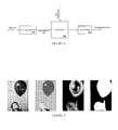
- the step 30 is detailed on figure 4 . It defines a forbidden area map where the cropping window cannot be located, such as on an object (white pixels of right image on figure 5 ).
- a color segmentation algorithm such as the one disclosed in J. van de Weijer et al "Learning Color Names for Real-World Applications” published in IEEE Transactions in Image Processing 2009 is used to get a segmentation map. Any other method providing a segmentation map can be used.
- the segmentation map is applied on one the views.
- a saliency value is computed for each color region identified in the segmentation map.
- the saliency values of the pixels belonging to a given region are averaged.
- the averaged value is considered as the saliency value of the region.
- the saliency values of the regions are thresholded. If the saliency quantity (or average of saliency) of a region is superior to a threshold T (Thresholding step) the final ForbiddenMap is set to 1 (or 255, white pixels) in this region. Such a black and white map with forbidden object is represented on figure 5 .
- T Thesholding step
- ⁇ R and ⁇ R are computed from the saliency map associated with the view used for the segmentation.
- step 32 the smoothed cropping window is determined. This step 32 is detailed on figure 6 .
- a first cropping window is determined for each view independently.
- the goal of step 322 is to define, for each view, a cropping window that encloses the most conspicuous parts of the considered view S(x,y) of width W and height H from its saliency map SM(x,y).
- Many 2D reframing methods may be applied.
- the saliency map is first binarized to identify the most salient areas. The pixels having a saliency value greater that a threshold are set to 255 in the binarized map. The smallest window that comprises all the identified salient areas, i.e. the white pixels, is the first cropping window.
- a Winner-Take-All algorithm is purposely employed to select K areas A k with 1 ⁇ k ⁇ K among the WxH candidates.
- the subset M with the K first pixels having the highest saliency value and the minimum distance to the center is computed, such as described by the equation 4.
- a k is the set of pixels in a circle having a radius equal to 1 degree of visual angle.
- a saliency map may have many pixels at the maximum value; therefore the pixels closer to the center of the picture are favored.
- the bias of scene center has an important role: observers tend to fixate near the center of scenes, even if the salience is null.
- the iteration number (or in other words the number K), it is important to underline the influence of this parameter on the size of the cropping window. If the iteration number is weak (or in other words, the number K of location is weak), it is likely that the size of the cropping window will be small. On the contrary, a high number of iteration will likely ensure a larger bounding box.
- this approach seems to be convenient, one aspect is clearly neglected: the distribution of salience in the saliency map. This aspect is illustrated with figure 7 which represents two different images. Indeed, the distribution of the salience (or the average observer variability) is likely to be sparse on a picture of a landscape. In other words, the separation between the salience of the peaks and the average background level is important.
- K is constrained by the saliency quantity SQ contained by the previous areas A 1 .. k . While the relation (3) is not verified, the iteration process continues.
- P is a maximal quantity applied to the total saliency quantity SQ total of the map, such as 0 ⁇ P ⁇ 1.
- SQ total of the map such as 0 ⁇ P ⁇ 1.
- the left and right cropping windows are combined into an intermediate cropping window of top left coordinates (x LR ,y LR ), of height h LR and of width W HR .
- the parameters (position, size) of the cropping window are filtered over time.
- This step is referred to as temporal consistency.
- the temporal consistency acts both on the position and the size of the cropping window and comprises stabilization of intermediate cropping window coordinates/size over time.
- the time is identified by an index i.
- Temporal consistency comprises for example two sequential steps a kalman filtering and a non linear filtering.
- the Kalman filter is first applied in order to better predict the trajectory of the current sample.
- the Kalman filter is featured by an appealing recursive nature. Rather than working on all of the previous data to provide an estimation (as a Wiener filter will do), the Kalman filter does not require the long-term previous data.
- the Kalman filter is a linear system in which the mean square error between the predicted output and the actual output is minimized.
- the Kalman filter takes into account the two inherent sources of inaccuracy within a system, process W i and measurement noise V i , in order to minimize the prediction error.
- X i is a general name standing for the vector of coordinates (x i LR , y i LR ) and for cropping window size (w i LR , h i LR ).
- A 1 0 0 1
- H 1 0 0 1
- Median filtering is an improvement that makes it possible to avoid unlikely samples.
- the only use of a Kalman filter is not sufficient to obtain a realistic effect.
- a non linear filtering is applied to remove short increase or decrease of the trajectory (horizontally or/and vertically) which may be disturbing. The long trajectory over frames is favoured to simulate natural camera motion.
- Each filtering is independently applied on the center coordinates and the size of the cropping window CW LR i (x LR ,y LR ,w LR ,h LR ).
- step 328 aspect ratio conversion is applied.
- the different variables and notations used are illustrated on figure 8 .
- the cropping window is extended in one direction or another one or even in each direction in different proportion.
- the retargeting is cubical because it is also based on the depth map.
- the motivation is to avoid border or strong disparity to be "cut" by the cropping window.
- An interesting solution is to include or reject totally some objects with the same disparity.
- the step 322 performs an accurate estimation of the most important regions following the borders of saliency peaks Ak (as represented on figure 7 ) which are fully uncorrelated from the aspect ratio of a retargeting application.
- the anisotropic extension refines the cropping window size by extending the cropping window CW SM i (x SM ,y SM ,w SM ,h SM ) in a direction depending on the current ratio R SM .
- the extension is either on width or height to reach the targeted aspect ratio R TG .
- d right and d left may be computed in different manner. Let us assume that the width w SM has to be extended to reach the final aspect ratio.
- the depth map and/or the forbidden area map are used to extend the cropping window in one direction or another one.
- the depth map may be available or not depending on the use case. Consequently, two variants of aspect ratio conversion step 328 are disclosed one used when depth map is not available and one when the depth map is available.
- step 30 When the depth map is not available, only the forbidden area map of step 30 is used.
- the sum of gradients (Global Gradient or GG) in the columns of pixels adjacent to the SmoothedLRCoord window are computed in order to characterize the quantity and representation of each extension side. The same may be applied horizontally.
- a window (at the target aspect ratio) is determined by doing a horizontal translation under x axis in the interval [x SM -dw-w SM /2; x SM -w SM /2] so that equation (14) is minimized.
- d w is the maximal extension width.
- x opt x SM +d x (d x defined in (13))
- d left x SM -x min -w sm /2
- d right d w - d left
- d right is first determined by doing a horizontal translation under x axis in the interval [x SM +w SM /2;x SM +dw+w SM /2] so that equation (14) is minimized.
- a window (at the target aspect ratio) is determined by doing a horizontal translation under x axis in the interval [x SM -dw-w SM /2; x SM -w SM /2] so that equation (15) is maximized.
- d w is the maximal extension width.
- d right is first determined by doing a horizontal translation under x axis in the interval [x SM +w SM /2;x SM +dw+w SM /2] so that equation (15) is maximized.
- both left and right views are cropped into a left crop view and a right crop view by extracting in each view the part delimited by the smoothed cropping window.
- Figure 9 represents on the top left-hand side a saliency map, on the top right-hand side the first saliency peaks and the corresponding first cropping window (step 322).
- the bottom left-hand side image is the forbidden area map and the sliding window which has to minimize several quantities to be the final cropping window.
- the bottom right-hand side presents the final left and right chosen quantities to avoid cutting of objects.
- the forbidden area map indicates regions (in white) where final cropping window borders is to be avoided
- the retargeting method according to the invention is fully automatic, ensures a good final quality without missing fundamental parts for the global understanding of the scene and improves the 3D effects and the immersive experience in comparison with the version with black stripes.
Abstract
The invention relates to a method of cropping a 3D content comprising at least a first view and a second view t comprising the steps of:
- determining (10, 12) a first saliency map from the first view and a second saliency map from the second view;
- determining (18, 24, 32) a final cropping window from the first and second saliency maps; and
- cropping (20) the first view and the second view according to the final cropping window.
- determining (10, 12) a first saliency map from the first view and a second saliency map from the second view;
- determining (18, 24, 32) a final cropping window from the first and second saliency maps; and
- cropping (20) the first view and the second view according to the final cropping window.
Description
- The invention relates to 3D content retargeting. More particularly, it concerns a method of cropping a 3D content comprising at least a first view and a second view.
- Due to the proliferation of 3D screen and materials, such as 3D movie at the theater, there is a need for aspect ratio conversion in order to allow the transfer of 3D streams from the cinema aspect ratio (2:35) to TV screen (16:9). Moreover, one can imagine the imminent emergence of new devices such as tablets, smartphones supporting 3D stereoscopic display. Such devices will bring their own aspect ratio. Aspect ratio conversion is thus mandatory to address any devices. An automatic solution is of high value maximizing the visual comfort.
Currently, the aspect ratio conversion is addressed either manually by an operator (e.g. centered cropping) or by processing all frames in the same way (e.g. anamorphism operator, black stripes filling). Both types of methods do not take into account the content itself for performing the conversion. Moreover, black stripes addition strongly reduces the original 3D effect compared to having the movie displayed in full screen. - The invention is aimed at alleviating at least one of the drawbacks of the prior art. The invention relates to a method of cropping a 3D content comprising at least a first view and a second view comprising the steps of:
- determining a first saliency map from the first view and a second saliency map from the second view;
- determining a final cropping window from the first and second saliency maps; and
- cropping the first view and the second view according to the final cropping window.
- According to a first embodiment, the step of determining the final cropping window from the first and second saliency maps comprises the steps of:
- determining a first cropping window from the first saliency map;
- determining a second cropping window from the second saliency map; and
- combining the first and second cropping windows into the final cropping window.
- According to a second embodiment, the final cropping window being identified by parameters, the method further comprises the steps of:
- filtering over time the parameters of the final cropping window ;
- determining a forbidden area map indicating regions where final cropping window borders is to be avoided;
and - converting the aspect ratio of the final cropping window into a target aspect ratio using the forbidden area map.
- According to a variant of the second embodiment, the final cropping window being identified by parameters, the method further comprises the steps of:
- filtering over time the parameters of the final cropping window ;
- determining a forbidden area map indicating regions where final cropping window borders is to be avoided;
and - converting the aspect ratio of the final cropping window into a target aspect ratio using the forbidden area map and a depth map.
- Advantageously, the step of determining the forbidden area map comprises the steps of:
- segmenting one of the at least two views into a segmentation map of regions;
- computing, for each region of the segmentation map, a saliency value from the saliency map of the one of the at least two views;
- thresholding the saliency values computed for each region to form a forbidden area map.
- According to a third embodiment, the step of determining a final cropping window from the first and second saliency maps comprises the steps of:
- combining the first and second saliency maps into a single saliency map; and
- determining the final cropping window based on the single saliency map.
- Other features and advantages of the invention will appear with the following description of some of its embodiments, this description being made in connection with the drawings in which:
-
Figure 1 depicts a flowchart of the method according to a first embodiment of the invention ; -
Figure 2 depicts a flowchart of the method according to a second embodiment of the invention ; -
Figure 3 depicts a flowchart of the method according to a third embodiment of the invention ; -
Figure 4 represents a first detail of the flowchart depicted onfigure 3 ; -
Figure 5 represents from left to right, a picture, a segmentation map, a saliency map and a forbidden area map; -
Figure 6 represents another detail of the flowchart depicted onfigure 3 ; -
Figure 7 illustrates the winner-take all algorithm; -
Figure 8 represents cropping windows with their parameters; and -
Figure 9 represents a saliency map of a picture, a first cropping window onto the picture; a forbidden area map and a final cropping window. - The invention relates to a method for retargeting 3D content. Three embodiments are disclosed herein. The two first embodiments are an extension of a 2D retargeting method. New steps are added to ensure acceptable 3D quality. The third embodiment is a retargeting method dedicated to 3D content. The 3D content is made of a left view and a right view. But the invention can be extended to more than two views. In the following a cropping window is identified by its parameters which are either the coordinates of its top left and bottom right pixels or the coordinates of its center and its height and width.
- All embodiments are cropping-based, i.e. a sub-area of pixels of the original views with the most important content are extracted. Moreover, the final cropping window is identical for the left and right views even if the determination of this final cropping window is based on content of each view. All embodiments refer to a visual attention model. This visual attention model provides a saliency map (grey level map) which indicates which area/pixels are the most visually attractive in the view. An example of such a visual attention model is disclosed in
EP patent application 04804828.4 published on 30/06/2005 1695288 . Other visual attention models that provide a saliency map can be used. The invention is not at all limited to the model disclosed inEP patent application 04804828.4 -
Figure 1 represents a method of retargeting a 3D content comprising left and right views according to the first embodiment. It comprises applying regular 2D reframing on each view independently in order to get one cropping window in each view and then in combining all the cropping window by taking into account some constraints related to 3D content in order to get a final cropping window that is to be applied on each view.
To this aim, atstep 10, a left saliency map is determined for the left view and at step 12 a right saliency map is determined for the right view. Both saliency maps are for example determined using the model ofEP patent application 04804828.4 - At
step 14, a left cropping window is determined based on the left saliency map and at step 16 a right cropping window is determined based on the right saliency map. The position of each cropping window is identified in the corresponding view by its CropWind coordinates. The cropping windows are determined for example using one of the reframing method disclosed inEP application 05291938.8 published on 21/03/2007 1764736 . As an example, the most salient pixel is identified in the saliency map, i.e. whose saliency value within saliency map is the highest. A first window of predefined size is positioned in the view so that its center is located on this most salient pixel. The saliency value SM1 associated to the first window and the saliency value SMview associated to the view are computed. If the ratio

Atstep 18, the left and right cropping windows are combined in a smoothed cropping window. During this step, the following constraint linked to 3D content is taken into account: no vertical disparity is allowed between left and right cropped views; the cropping windows of each view have the same height and the same vertical coordinates. - The
CombineCroppingWindow step 18 takes the results for the 2D reframing applied on each view separately atsteps 

Another way for determining the smoothed cropping window is to determine which cropping window maximizes the saliency quantity available inside it. The cropping window coordinates vary from the minimal x and y coordinates initially determined between the two views and the maximal x and y coordinates, such as described in the following equation:
SMleft(x,y) is the saliency value of pixel (x,y) in the left view and SMright(x,y) is the saliency value of pixel (x,y) in the left view. (x1,y1) are the coordinates of the top left pixel of the smooth cropping window and (x2, y2) are the coordinates of the bottom right pixel of the smooth cropping window. (x1 left,y1 left) are the coordinates of the top left pixel of the left cropping window and (x2left,y2left ) are the coordinates of the bottom right pixel of the left cropping window. (x1 right,y1 right ) are the coordinates of the top left pixel of the right cropping window and (x2right ,y2left ) are the coordinates of the bottom right pixel of the left cropping window. - At
step 20, both left and right views are cropped into a left crop view and a right crop view by extracting in each view the part delimited by the smoothed cropping window.
The first embodiment is simple and fast to implement. -
Figure 2 represents the second embodiment. The steps identical to the steps of the first embodiment are identified onfigure 2 with the same numerical references.
Atstep 10, a left saliency map is determined for the left view and at step 12 a right saliency map is determined for the right view.
Atstep 22, the two saliency maps coming from the visual attention model for each view are combined into a unique saliency map which describes a 3D saliency information but with a 2D representation of the saliency map. TheCombineForVAM3D step 22 highlights the common areas present in the two saliency maps to create a unique 2D saliency map. Duringstep 22, both saliency maps are merged into a unique saliency map (SaliencyMap_3Dlike) which is a 2D map highlighting some areas which are commonly salient in the two views. As an example, the saliency value SM3Dlike (x,y) for the pixel (x,y) in the SaliencyMap_3Dlike is defined as follows:
where SMleft(x,y) is the saliency value of the pixel (x,y) in the left saliency map, SMright(x,y) is the saliency value of the pixel (x,y) in the right saliency map and DM(x,y) is the depth value at location (x,y). - At
step 24, a smoothed cropping window is determined based on the SaliencyMap_3Dlike.Step 24 is for example identical to step 14 or 16 but with the saliency map being the SaliencyMap_3Dlike. - At
step 20, both left and right views are cropped into a left crop view and a right crop view by extracting in each view the part delimited by the smoothed cropping window. -
Figure 3 represents the third embodiment. This embodiment is dedicated to 3D content. The decision about the cropping window extension uses possibly the depth map. 3 dimensional data are used to determine the smoothed cropping window. - The steps identical to the steps of the first embodiment are identified on
figure 2 with the same numerical references. - At
step 10, a left saliency map is determined for the left view and at step 12 a right saliency map is determined for the right view. - At
step 30, referred to as CreateForbiddenAreaMap step provides a map to aReframing3D step 32 which ensure the respect of some 3D constraints: no object on the border of the cropping window is allowed if this object is in front of the screen. Indeed, human brain cannot deal with that. The forbidden area map is created from one of the views either the left or the right. Onfigures 3 and4 the forbidden area map is created from the left view but the same can be made from the right view. - The
step 30 is detailed onfigure 4 . It defines a forbidden area map where the cropping window cannot be located, such as on an object (white pixels of right image onfigure 5 ). - At
step 300, a color segmentation algorithm such as the one disclosed in J. van de Weijer et al "Learning Color Names for Real-World Applications" published in IEEE Transactions in Image Processing 2009 is used to get a segmentation map. Any other method providing a segmentation map can be used. The segmentation map is applied on one the views. - At
step 302, a saliency value is computed for each color region identified in the segmentation map. As an example, the saliency values of the pixels belonging to a given region are averaged. The averaged value is considered as the saliency value of the region. - At
step 304, the saliency values of the regions are thresholded. If the saliency quantity (or average of saliency) of a region is superior to a threshold T (Thresholding step) the final ForbiddenMap is set to 1 (or 255, white pixels) in this region. Such a black and white map with forbidden object is represented onfigure 5 . Following equation summarizes the computation of threshold T which is adaptive:
where µR and σ R are respectively the average and the standard deviation of the region R. µR and σ R are computed from the saliency map associated with the view used for the segmentation. - At
step 32, the smoothed cropping window is determined. Thisstep 32 is detailed onfigure 6 . - At
step 322, a first cropping window is determined for each view independently. The goal ofstep 322 is to define, for each view, a cropping window that encloses the most conspicuous parts of the considered view S(x,y) of width W and height H from its saliency map SM(x,y). Many 2D reframing methods may be applied. As an example, the saliency map is first binarized to identify the most salient areas. The pixels having a saliency value greater that a threshold are set to 255 in the binarized map. The smallest window that comprises all the identified salient areas, i.e. the white pixels, is the first cropping window. - According to a variant, a Winner-Take-All algorithm is purposely employed to select K areas Ak with 1 < k < K among the WxH candidates. This selection is composed of two steps. First, the view S(x,y) is scanned on a pixel-by-pixel basis and at each pixel position p(x,y) a feature vector


- A saliency map may have many pixels at the maximum value; therefore the pixels closer to the center of the picture are favored. The bias of scene center has an important role: observers tend to fixate near the center of scenes, even if the salience is null.
- Concerning the iteration number (or in other words the number K), it is important to underline the influence of this parameter on the size of the cropping window. If the iteration number is weak (or in other words, the number K of location is weak), it is likely that the size of the cropping window will be small. On the contrary, a high number of iteration will likely ensure a larger bounding box. Although this approach seems to be convenient, one aspect is clearly neglected: the distribution of salience in the saliency map. This aspect is illustrated with
figure 7 which represents two different images. Indeed, the distribution of the salience (or the average observer variability) is likely to be sparse on a picture of a landscape. In other words, the separation between the salience of the peaks and the average background level is important. Concerning an image of landscape, in which nothing clearly popsout, the distribution of salience is more uniform. In this case, selecting the K first locations can yield an erroneous result. To solve this problem, the iteration is monitored by the amount of salience enclosed by the bounding box. Therefore, K is constrained by the saliency quantity SQ contained by the previous areas A1..k. While the relation (3) is not verified, the iteration process continues. K is adjusted in order to have P percent of the saliency in the cropping window, such as:


- P is a maximal quantity applied to the total saliency quantity SQtotal of the map, such as 0 < P < 1. An example of such cropping windows is illustrated on
figure 7 . - At
step 324, the left and right cropping windows are combined into an intermediate cropping window of top left coordinates (xLR,yLR), of height hLR and of width WHR. The combination of the left and right cropping windows is done by applying a max and min operators on each x and y component:
- Another solution is to apply the solution of equation (1) of the CombineCroppingWindow module.
- At
step 326, the parameters (position, size) of the cropping window are filtered over time. This step is referred to as temporal consistency. The temporal consistency acts both on the position and the size of the cropping window and comprises stabilization of intermediate cropping window coordinates/size over time. The time is identified by an index i. Temporal consistency comprises for example two sequential steps a kalman filtering and a non linear filtering. - The Kalman filter is first applied in order to better predict the trajectory of the current sample. The Kalman filter is featured by an appealing recursive nature. Rather than working on all of the previous data to provide an estimation (as a Wiener filter will do), the Kalman filter does not require the long-term previous data. The Kalman filter is a linear system in which the mean square error between the predicted output and the actual output is minimized. The Kalman filter takes into account the two inherent sources of inaccuracy within a system, process Wi and measurement noise Vi, in order to minimize the prediction error. In the following equation, Xi is a general name standing for the vector of coordinates (xi LR, yi LR) and for cropping window size (wi LR, hi LR). The Kalman filter is defined by the state (eq. 9) and the measurement equation (eq. 10):


- Where A is a constant transition matrix and H is also a constant measurement matrix.

- W and V (matrix 1x2) represent the process and the measurement noise, respectively. They are assumed to be independent, white and with normal probability. They are empirically set and the associated noise covariance matrix is given by R and Q. Kalman filtering is detailed in document from G. Welch and G. Bishop entitled "An introduction to the kalman filter," published in Course 8, SIGGRAPH 2001, 2001.

- The determination of the process noise is quite difficult. In this study, the process noise covariance is constant. The higher the uncertainty is, the faster the filter converges. The cropping window will have the tendency to fast adapt to the new saliency changes. The filter has to converge moderately fast because it should consider to be close to camera motion.
- Median filtering is an improvement that makes it possible to avoid unlikely samples. The only use of a Kalman filter is not sufficient to obtain a realistic effect. A non linear filtering is applied to remove short increase or decrease of the trajectory (horizontally or/and vertically) which may be disturbing. The long trajectory over frames is favoured to simulate natural camera motion. Each filtering is independently applied on the center coordinates and the size of the cropping window CWLR i(xLR,yLR,wLR,hLR). The result of this step is a cropping window CWTC i (xTC,yTC,wTC,hTC) = (xsmooth,ysmooth,wsmooth,hsmooth) with a smooth spatial trajectory and size.
- At
step 328, aspect ratio conversion is applied. The different variables and notations used are illustrated onfigure 8 . The cropping window is extended in one direction or another one or even in each direction in different proportion. The retargeting is cubical because it is also based on the depth map. The motivation is to avoid border or strong disparity to be "cut" by the cropping window. An interesting solution is to include or reject totally some objects with the same disparity. - There is no relation (no conjoint analysis) between the size of the intermediate window extracted from the saliency maps and the final aspect ratio defined by the user settings or application. Indeed, the
step 322 performs an accurate estimation of the most important regions following the borders of saliency peaks Ak (as represented onfigure 7 ) which are fully uncorrelated from the aspect ratio of a retargeting application. The anisotropic extension refines the cropping window size by extending the cropping window CWSM i (xSM,ySM,wSM,hSM) in a direction depending on the current ratio RSM. The extension is either on width or height to reach the targeted aspect ratio RTG. Let us assume that: -

-

- If RTG > RSM, horizontal extension is performed (on the width of the current rectangle) else vertical extension is done (on the height of the current rectangle). Assuming a horizontal extension (respectively a vertical extension), one can define:

- Once the side of extension is defined, there are still several ways to extend the window. In other words, dright and dleft may be computed in different manner. Let us assume that the width wSM has to be extended to reach the final aspect ratio.
- The depth map and/or the forbidden area map are used to extend the cropping window in one direction or another one.
- The depth map may be available or not depending on the use case. Consequently, two variants of aspect
ratio conversion step 328 are disclosed one used when depth map is not available and one when the depth map is available. - When the depth map is not available, only the forbidden area map of
step 30 is used. The sum of gradients (Global Gradient or GG) in the columns of pixels adjacent to the SmoothedLRCoord window are computed in order to characterize the quantity and representation of each extension side. The same may be applied horizontally. The optimal cropping window CW(xopt,yopt) is found when the following problem of minimization has a solution (assuming yopt = ySM):
- Indeed, a window (at the target aspect ratio) is determined by doing a horizontal translation under x axis in the interval [xSM-dw-wSM/2; xSM-wSM/2] so that equation (14) is minimized. dw is the maximal extension width.
- The corresponding xmin is the left side of the optimal cropping window. Then, xopt = xSM+dx (dx defined in (13))
dleft = xSM-xmin-wsm/2
dright = dw - dleft - According to a variant, dright is first determined by doing a horizontal translation under x axis in the interval [xSM+wSM/2;xSM+dw+wSM/2] so that equation (14) is minimized.
- When there is no solution to the minimization problem, the extension is done equally to each side, that means: dleft = dright = dw /2
- When the depth map is available, a confidence Confx on both maps is computed. This confidence is then maximized in order to find the best cropping window.

- Indeed, a window (at the target aspect ratio) is determined by doing a horizontal translation under x axis in the interval [xSM-dw-wSM/2; xSM-wSM/2] so that equation (15) is maximized. dw is the maximal extension width.
- The corresponding Xmin is the left side of the optimal cropping window. Then, xopt = xSM+dx (dx defined in (13))
dleft = xSM-xmin-wsm/2
dright = dw - dleft - According to a variant, dright is first determined by doing a horizontal translation under x axis in the interval [xSM+wSM/2;xSM+dw+wSM/2] so that equation (15) is maximized.
- At
step 20, both left and right views are cropped into a left crop view and a right crop view by extracting in each view the part delimited by the smoothed cropping window. -
Figure 9 represents on the top left-hand side a saliency map, on the top right-hand side the first saliency peaks and the corresponding first cropping window (step 322). The bottom left-hand side image is the forbidden area map and the sliding window which has to minimize several quantities to be the final cropping window. The bottom right-hand side presents the final left and right chosen quantities to avoid cutting of objects. Indeed, the forbidden area map indicates regions (in white) where final cropping window borders is to be avoided - The retargeting method according to the invention is fully automatic, ensures a good final quality without missing fundamental parts for the global understanding of the scene and improves the 3D effects and the immersive experience in comparison with the version with black stripes.
- The invention may be advantageously for many post-production tasks such as:
- Content preparation for aspect ratio conversion. A TV owner will appreciate to have its content reformatted for several supports such as internet, mobile TV, regular TV channels...in the case of catch-up TV and VOD.
- Content preparation for blu-ray disk. An aspect ratio conversion from theater to TV aspect ratio is required in the preparation of the blu-ray support.
Claims (6)
- Method of cropping a 3D content comprising at least a first view and a second view characterized in that it comprising the steps of:- determining (10, 12) a first saliency map from said first view and a second saliency map from said second view;- determining (18, 24, 32) a final cropping window from said first and second saliency maps; and- cropping (20) said first view and said second view according to said final cropping window.
- Method according to claim 1, wherein the step of determining the final cropping window from said first and second saliency maps comprises the steps of:- determining (14, 322) a first cropping window from said first saliency map;- determining (16, 322) a second cropping window from said second saliency map; and- combining (18, 324) said first and second cropping windows into the final cropping window.
- Method according to claim 2, wherein the final cropping window being identified by parameters, the method further comprising the steps of:- filtering (326) over time the parameters of the final cropping window;- determining (30) a forbidden area map indicating regions where final cropping window borders is to be avoided;
and- converting (328) the aspect ratio of the final cropping window into a target aspect ratio using the forbidden area map. - Method according to claim 2, wherein the final cropping window being identified by parameters, the method further comprises the steps of:- filtering (326) over time the parameters of the final cropping window;- determining (30) a forbidden area map indicating regions where final cropping window borders is to be avoided;
and- converting (328) the aspect ratio of the final cropping window into a target aspect ratio using the forbidden area map and a depth map. - Method according to claim 3 or 4, wherein the step (30) of determining the forbidden area map comprises the steps of:- segmenting (300) one of said at least two views into a segmentation map of regions;- computing (302), for each region of the segmentation map, a saliency value from the saliency map of said one of said at least two views;- thresholding (304) said saliency values computed for each region to form a forbidden area map.
- Method according to claim 1, wherein the step of determining (24) a final cropping window from said first and second saliency maps comprises the steps of:- combining (22) said first and second saliency maps into a single saliency map; and- determining (24) the final cropping window based on the single saliency map.
Priority Applications (8)
| Application Number | Priority Date | Filing Date | Title |
|---|---|---|---|
| EP11305661A EP2530642A1 (en) | 2011-05-31 | 2011-05-31 | Method of cropping a 3D content |
| TW101115871A TWI553590B (en) | 2011-05-31 | 2012-05-04 | Method and device for retargeting a 3d content |
| US14/123,213 US9743062B2 (en) | 2011-05-31 | 2012-05-23 | Method and device for retargeting a 3D content |
| CN201280026599.5A CN103582900A (en) | 2011-05-31 | 2012-05-23 | Method and device for retargeting 3D content |
| KR1020137031641A KR20140038436A (en) | 2011-05-31 | 2012-05-23 | Method and device for retargeting a 3d content |
| EP12723455.7A EP2715660A1 (en) | 2011-05-31 | 2012-05-23 | Method and device for retargeting a 3d content |
| PCT/EP2012/059535 WO2012163743A1 (en) | 2011-05-31 | 2012-05-23 | Method and device for retargeting a 3d content |
| JP2014513121A JP6039657B2 (en) | 2011-05-31 | 2012-05-23 | Method and device for retargeting 3D content |
Applications Claiming Priority (1)
| Application Number | Priority Date | Filing Date | Title |
|---|---|---|---|
| EP11305661A EP2530642A1 (en) | 2011-05-31 | 2011-05-31 | Method of cropping a 3D content |
Publications (1)
| Publication Number | Publication Date |
|---|---|
| EP2530642A1 true EP2530642A1 (en) | 2012-12-05 |
Family
ID=44558272
Family Applications (2)
| Application Number | Title | Priority Date | Filing Date |
|---|---|---|---|
| EP11305661A Withdrawn EP2530642A1 (en) | 2011-05-31 | 2011-05-31 | Method of cropping a 3D content |
| EP12723455.7A Withdrawn EP2715660A1 (en) | 2011-05-31 | 2012-05-23 | Method and device for retargeting a 3d content |
Family Applications After (1)
| Application Number | Title | Priority Date | Filing Date |
|---|---|---|---|
| EP12723455.7A Withdrawn EP2715660A1 (en) | 2011-05-31 | 2012-05-23 | Method and device for retargeting a 3d content |
Country Status (7)
| Country | Link |
|---|---|
| US (1) | US9743062B2 (en) |
| EP (2) | EP2530642A1 (en) |
| JP (1) | JP6039657B2 (en) |
| KR (1) | KR20140038436A (en) |
| CN (1) | CN103582900A (en) |
| TW (1) | TWI553590B (en) |
| WO (1) | WO2012163743A1 (en) |
Families Citing this family (8)
| Publication number | Priority date | Publication date | Assignee | Title |
|---|---|---|---|---|
| EP2894852A1 (en) * | 2014-01-14 | 2015-07-15 | Alcatel Lucent | Process for increasing the quality of experience for users that watch on their terminals a high definition video stream |
| US9626584B2 (en) * | 2014-10-09 | 2017-04-18 | Adobe Systems Incorporated | Image cropping suggestion using multiple saliency maps |
| US9805445B2 (en) * | 2014-10-27 | 2017-10-31 | Adobe Systems Incorporated | Image zooming |
| WO2016204481A1 (en) * | 2015-06-16 | 2016-12-22 | 엘지전자 주식회사 | Media data transmission device, media data reception device, media data transmission method, and media data rececption method |
| EP3223524A1 (en) | 2016-03-22 | 2017-09-27 | Thomson Licensing | Method, apparatus and stream of formatting an immersive video for legacy and immersive rendering devices |
| EP3306928A1 (en) * | 2016-10-07 | 2018-04-11 | Thomson Licensing | Method and apparatus for encoding a video |
| KR20180070297A (en) | 2016-12-16 | 2018-06-26 | 삼성전자주식회사 | Display apparatus and control method thereof |
| US20210398333A1 (en) * | 2020-06-19 | 2021-12-23 | Apple Inc. | Smart Cropping of Images |
Citations (3)
| Publication number | Priority date | Publication date | Assignee | Title |
|---|---|---|---|---|
| EP1695288A1 (en) | 2003-12-18 | 2006-08-30 | Thomson Licensing | Device and method for creating a saliency map of an image |
| EP1764736A1 (en) | 2005-09-19 | 2007-03-21 | Thomson Licensing | Method and device for image cropping |
| US20110038529A1 (en) * | 2009-08-12 | 2011-02-17 | Hitachi, Ltd. | Image processing apparatus and image processing method |
Family Cites Families (22)
| Publication number | Priority date | Publication date | Assignee | Title |
|---|---|---|---|---|
| DE3632529A1 (en) | 1986-09-25 | 1988-04-07 | Basf Ag | METHOD FOR PRODUCING ALDEHYDES AND / OR KETONES BY REALIZING EPOXIES |
| JPH0563978A (en) | 1991-08-30 | 1993-03-12 | Toshiba Corp | Picture reader |
| GB2372659A (en) | 2001-02-23 | 2002-08-28 | Sharp Kk | A method of rectifying a stereoscopic image |
| JP2005072674A (en) | 2003-08-27 | 2005-03-17 | Sharp Corp | Three-dimensional image generating apparatus and three-dimensional image generating system |
| KR101093572B1 (en) | 2004-10-06 | 2011-12-14 | 톰슨 라이센싱 | Method and apparatus for providing a picture cropping function |
| WO2006106522A2 (en) * | 2005-04-07 | 2006-10-12 | Visionsense Ltd. | Method for reconstructing a three- dimensional surface of an object |
| TW200719281A (en) | 2005-07-28 | 2007-05-16 | Thomson Licensing | Method and device for generating a sequence of images of reduced size |
| JP4249187B2 (en) | 2006-01-13 | 2009-04-02 | エヌ・ティ・ティ・コムウェア株式会社 | 3D image processing apparatus and program thereof |
| TW200733741A (en) * | 2006-02-20 | 2007-09-01 | Inventec Appliances Corp | Method for converting image screen specification for handheld multimedia playing device |
| WO2008028334A1 (en) | 2006-09-01 | 2008-03-13 | Thomson Licensing | Method and device for adaptive video presentation |
| FR2912237A1 (en) | 2007-02-07 | 2008-08-08 | Thomson Licensing Sas | IMAGE PROCESSING METHOD |
| US8824833B2 (en) * | 2008-02-01 | 2014-09-02 | Omnivision Technologies, Inc. | Image data fusion systems and methods |
| TW200937344A (en) | 2008-02-20 | 2009-09-01 | Ind Tech Res Inst | Parallel processing method for synthesizing an image with multi-view images |
| JP2009212929A (en) | 2008-03-05 | 2009-09-17 | Fujifilm Corp | Method, apparatus and program for evaluating image trimming range |
| US9240056B2 (en) | 2008-04-02 | 2016-01-19 | Microsoft Technology Licensing, Llc | Video retargeting |
| FR2929797A1 (en) | 2008-04-03 | 2009-10-09 | Thomson Licensing Sas | METHOD AND DEVICE FOR ENCODING AN IMAGE SEQUENCE |
| US20100259595A1 (en) * | 2009-04-10 | 2010-10-14 | Nokia Corporation | Methods and Apparatuses for Efficient Streaming of Free View Point Video |
| US8711204B2 (en) | 2009-11-11 | 2014-04-29 | Disney Enterprises, Inc. | Stereoscopic editing for video production, post-production and display adaptation |
| US9142026B2 (en) * | 2010-02-26 | 2015-09-22 | Thomson Licensing | Confidence map, method for generating the same and method for refining a disparity map |
| EP2656613A1 (en) * | 2010-12-22 | 2013-10-30 | Thomson Licensing | Apparatus and method for determining a disparity estimate |
| FR2968108A1 (en) | 2011-06-20 | 2012-06-01 | Thomson Licensing | Method for processing video image to display stereoscopic image on target screen of e.g. TV, involves calculating target disparity information associated to part of image according to disparity budget and original disparity information |
| KR102111181B1 (en) * | 2012-08-21 | 2020-05-15 | 포토내이션 리미티드 | Systems and methods for parallax detection and correction in images captured using array cameras |
-
2011
- 2011-05-31 EP EP11305661A patent/EP2530642A1/en not_active Withdrawn
-
2012
- 2012-05-04 TW TW101115871A patent/TWI553590B/en not_active IP Right Cessation
- 2012-05-23 US US14/123,213 patent/US9743062B2/en not_active Expired - Fee Related
- 2012-05-23 JP JP2014513121A patent/JP6039657B2/en not_active Expired - Fee Related
- 2012-05-23 CN CN201280026599.5A patent/CN103582900A/en active Pending
- 2012-05-23 KR KR1020137031641A patent/KR20140038436A/en not_active Application Discontinuation
- 2012-05-23 EP EP12723455.7A patent/EP2715660A1/en not_active Withdrawn
- 2012-05-23 WO PCT/EP2012/059535 patent/WO2012163743A1/en active Application Filing
Patent Citations (3)
| Publication number | Priority date | Publication date | Assignee | Title |
|---|---|---|---|---|
| EP1695288A1 (en) | 2003-12-18 | 2006-08-30 | Thomson Licensing | Device and method for creating a saliency map of an image |
| EP1764736A1 (en) | 2005-09-19 | 2007-03-21 | Thomson Licensing | Method and device for image cropping |
| US20110038529A1 (en) * | 2009-08-12 | 2011-02-17 | Hitachi, Ltd. | Image processing apparatus and image processing method |
Non-Patent Citations (5)
| Title |
|---|
| CHAMARET C ET AL: "Attention-based video reframing: Validation using eye-tracking", 19TH INTERNATIONAL CONFERENCE ON PATTERN RECOGNITION, 2008: ICPR 2008; 8 - 11 DEC. 2008, TAMPA, FLORIDA, USA, IEEE, PISCATAWAY, NJ, 8 December 2008 (2008-12-08), pages 1 - 4, XP031412162, ISBN: 978-1-4244-2174-9 * |
| G. WELCH, G. BISHOP: "An introduction to the kalman filter", COURSE 8, SIGGRAPH 2001, 2001 |
| J. VAN DE WEIJER ET AL.: "Learning Color Names for Real-World Applications", IEEE TRANSACTIONS IN IMAGE PROCESSING, 2009 |
| KEI UTSUGI ET AL: "Seam carving for stereo images", 3DTV-CONFERENCE: THE TRUE VISION - CAPTURE, TRANSMISSION AND DISPLAY OF 3D VIDEO (3DTV-CON), 2010, IEEE, PISCATAWAY, NJ, USA, 7 June 2010 (2010-06-07), pages 1 - 4, XP031706344, ISBN: 978-1-4244-6377-0 * |
| VAQUERO D ET AL: "A survey of image retargeting techniques", PROCEEDINGS OF SPIE, THE INTERNATIONAL SOCIETY FOR OPTICAL ENGINEERING SPIE, USA, vol. 7798, 2 August 2010 (2010-08-02), pages 779814 - 1, XP002646537, ISSN: 0277-786X, DOI: 10.1117/12.862419 * |
Also Published As
| Publication number | Publication date |
|---|---|
| TWI553590B (en) | 2016-10-11 |
| US20140232821A1 (en) | 2014-08-21 |
| CN103582900A (en) | 2014-02-12 |
| JP2014522596A (en) | 2014-09-04 |
| WO2012163743A1 (en) | 2012-12-06 |
| US9743062B2 (en) | 2017-08-22 |
| EP2715660A1 (en) | 2014-04-09 |
| KR20140038436A (en) | 2014-03-28 |
| TW201248545A (en) | 2012-12-01 |
| JP6039657B2 (en) | 2016-12-07 |
Similar Documents
| Publication | Publication Date | Title |
|---|---|---|
| EP2530642A1 (en) | Method of cropping a 3D content | |
| US11017586B2 (en) | 3D motion effect from a 2D image | |
| US9117295B2 (en) | Refinement of depth maps by fusion of multiple estimates | |
| US8340422B2 (en) | Generation of depth map for an image | |
| US8780172B2 (en) | Depth and video co-processing | |
| CN102741879B (en) | Method for generating depth maps from monocular images and systems using the same | |
| US8861836B2 (en) | Methods and systems for 2D to 3D conversion from a portrait image | |
| EP2074586B1 (en) | Image enhancement | |
| EP2481023B1 (en) | 2d to 3d video conversion | |
| JP4966431B2 (en) | Image processing device | |
| US9076234B2 (en) | Super-resolution method and apparatus for video image | |
| KR101584115B1 (en) | Device for generating visual attention map and method thereof | |
| KR101690297B1 (en) | Image converting device and three dimensional image display device including the same | |
| US20160063316A1 (en) | Methods and systems for increasing facial recognition working rang through adaptive super-resolution | |
| CN103440664B (en) | Method, system and computing device for generating high-resolution depth map | |
| EP2466901B1 (en) | Depth data upsampling | |
| JP2014522596A5 (en) | ||
| EP3298578B1 (en) | Method and apparatus for determining a depth map for an image | |
| JPWO2015156149A1 (en) | Image processing apparatus and image processing method | |
| US20070008342A1 (en) | Segmentation refinement | |
| US8902359B1 (en) | Processor implemented systems and methods for handling of occlusion for frame rate upconversion | |
| CN110602479A (en) | Video conversion method and system | |
| Sethi et al. | Multi-Operator based Saliency Detection | |
| CN115965531A (en) | Model training method, image generation method, device, equipment and storage medium |
Legal Events
| Date | Code | Title | Description |
|---|---|---|---|
| PUAI | Public reference made under article 153(3) epc to a published international application that has entered the european phase |
Free format text: ORIGINAL CODE: 0009012 |
|
| AK | Designated contracting states |
Kind code of ref document: A1 Designated state(s): AL AT BE BG CH CY CZ DE DK EE ES FI FR GB GR HR HU IE IS IT LI LT LU LV MC MK MT NL NO PL PT RO RS SE SI SK SM TR |
|
| AX | Request for extension of the european patent |
Extension state: BA ME |
|
| STAA | Information on the status of an ep patent application or granted ep patent |
Free format text: STATUS: THE APPLICATION IS DEEMED TO BE WITHDRAWN |
|
| 18D | Application deemed to be withdrawn |
Effective date: 20130606 |