EP2526748B1 - Adjustable blanking panel - Google Patents
Adjustable blanking panel Download PDFInfo
- Publication number
- EP2526748B1 EP2526748B1 EP11735010.8A EP11735010A EP2526748B1 EP 2526748 B1 EP2526748 B1 EP 2526748B1 EP 11735010 A EP11735010 A EP 11735010A EP 2526748 B1 EP2526748 B1 EP 2526748B1
- Authority
- EP
- European Patent Office
- Prior art keywords
- base member
- pair
- mounting
- mounting holes
- sliding member
- Prior art date
- Legal status (The legal status is an assumption and is not a legal conclusion. Google has not performed a legal analysis and makes no representation as to the accuracy of the status listed.)
- Active
Links
- 238000000034 method Methods 0.000 claims description 8
- 230000008878 coupling Effects 0.000 claims description 4
- 238000010168 coupling process Methods 0.000 claims description 4
- 238000005859 coupling reaction Methods 0.000 claims description 4
- 239000000463 material Substances 0.000 description 3
- 238000010276 construction Methods 0.000 description 2
- 239000000945 filler Substances 0.000 description 2
- 238000007726 management method Methods 0.000 description 2
- RZVHIXYEVGDQDX-UHFFFAOYSA-N 9,10-anthraquinone Chemical compound C1=CC=C2C(=O)C3=CC=CC=C3C(=O)C2=C1 RZVHIXYEVGDQDX-UHFFFAOYSA-N 0.000 description 1
- 230000004888 barrier function Effects 0.000 description 1
- 238000013500 data storage Methods 0.000 description 1
- 230000001419 dependent effect Effects 0.000 description 1
- 230000006870 function Effects 0.000 description 1
- 238000009434 installation Methods 0.000 description 1
- 239000002184 metal Substances 0.000 description 1
- 230000004048 modification Effects 0.000 description 1
- 238000012986 modification Methods 0.000 description 1
- 238000004886 process control Methods 0.000 description 1
- 230000003134 recirculating effect Effects 0.000 description 1
- 230000004044 response Effects 0.000 description 1
- 230000002441 reversible effect Effects 0.000 description 1
Images


Classifications
-
- H—ELECTRICITY
- H05—ELECTRIC TECHNIQUES NOT OTHERWISE PROVIDED FOR
- H05K—PRINTED CIRCUITS; CASINGS OR CONSTRUCTIONAL DETAILS OF ELECTRIC APPARATUS; MANUFACTURE OF ASSEMBLAGES OF ELECTRICAL COMPONENTS
- H05K7/00—Constructional details common to different types of electric apparatus
- H05K7/20—Modifications to facilitate cooling, ventilating, or heating
- H05K7/20709—Modifications to facilitate cooling, ventilating, or heating for server racks or cabinets; for data centers, e.g. 19-inch computer racks
- H05K7/20718—Forced ventilation of a gaseous coolant
- H05K7/20736—Forced ventilation of a gaseous coolant within cabinets for removing heat from server blades
-
- Y—GENERAL TAGGING OF NEW TECHNOLOGICAL DEVELOPMENTS; GENERAL TAGGING OF CROSS-SECTIONAL TECHNOLOGIES SPANNING OVER SEVERAL SECTIONS OF THE IPC; TECHNICAL SUBJECTS COVERED BY FORMER USPC CROSS-REFERENCE ART COLLECTIONS [XRACs] AND DIGESTS
- Y10—TECHNICAL SUBJECTS COVERED BY FORMER USPC
- Y10T—TECHNICAL SUBJECTS COVERED BY FORMER US CLASSIFICATION
- Y10T29/00—Metal working
- Y10T29/49—Method of mechanical manufacture
- Y10T29/49826—Assembling or joining
- Y10T29/49947—Assembling or joining by applying separate fastener
Definitions
- the invention relates to panels for use with cabinets and enclosures that house rack-mounted electrical and computer equipment. Specifically, the invention relates to height-adjustable panels for preventing the reentry of heated exhaust air into the air intake of the electrical or computer equipment.
- Electrical and computer equipment such as computer servers, data storage devices, and power supplies, are often mounted on a rack or frame using mounting members such as shelves, rails and/or brackets.
- these electronic components generate substantial heat that must be dissipated in order to maintain the devices in proper working order and prevent damage and possible failure.
- Most electronic device manufacturers require air of a specific temperature range to be drawn into the front of the device, passed over the internal components where the heat is exchanged, and exhausted out of the back of the device.
- Cabinets and enclosures, as well as the data centers or rooms that house the cabinets, are typically set up to accommodate this "front to back" air flow requirement.
- the racks or frames are not fully populated with components, resulting in vacant sections. This empty space may result in warm air from the back being drawn into the air intake at the front, which does not permit cooler air to be drawn into the electronic equipment, and may cause the equipment to overheat.
- WO 2008 144 678 A1 relates to an electronic equipment enclosure having a frame structure, enclosure panels mounted on the frame structure and at least one adjustable filler panel assembly. Each adjustable filler panel assembly selectively blocks a portion of an air inlet opening to prohibit air exhausted into the duct from flowing back into the enclosure.
- a height-adjustable blanking panel may also reduce the amount of labor hours expended when a cabinet or enclosure is reconfigured.
- the invention disclosed herein provides height-adjustable panels and systems for preventing the circular flow and reentry of high temperature air into the air intake of the electrical or computer equipment.
- an assembly as set forth in claim 1 and a method as set forth in claim 9 are provided. Further embodiments are inter alia disclosed in the dependent claims.
- the assembly is for use with an enclosure, where the enclosure comprises a pair of mounting rails, and each mounting rail defining a plurality of mounting holes.
- the assembly inter alia comprises a generally rectangular base member defining a top, a bottom, opposing left and right side channels, and a pair of mounting holes; and a generally rectangular sliding member defining a top, a bottom, opposing left and right sides, and a pair of mounting holes; where the base member mounting holes are sized and shaped to accommodate a first pair of fasteners inserted through the base member mounting holes and through a first pair of mounting rail mounting holes, to removably couple the base member to the pair of mounting rails; where the sliding member mounting holes are sized and shaped to accommodate a second pair of fasteners inserted through the sliding member mounting holes and through a second pair of mounting rail mounting holes, to removably couple the sliding member to the pair of mounting rails; and where the left and rights sides of the sliding member are located within the left and right side channels of the base member, respectively, such that the sliding member is adapted to slide relative to the base member.
- the top of the sliding member defines an upper lip, adapted to allow a user to raise or lower the sliding member relative to the base member.
- the bottom of the base member defines a lower lip, such that the bottom of the sliding member contacts and rests upon the lower lip when the sliding member is fully retracted.
- the top of the sliding member defines at least one upper tab, such that the upper tab contacts and rests upon the top of the base member when the sliding member is fully retracted.
- the left and right side channels are each defined by a first wall that is generally parallel to a front face of the base member, and a second wall that is generally perpendicular to the front face of the base member.
- the left and right side channels extend along the majority of the left and right sides, respectively, of the base member.
- the assembly comprises a base frame defining a generally rectangular rear section, and opposing left and right side retaining members; where the rear section of the base frame defines opposing front and rear sides, opposing top and bottom edges, and opposing left and right side edges; where the left and right side retaining members are coupled to the left and right side edges, respectively, of the rear section; a shield defining a generally rectangular panel section; where the panel section of the shield defines opposing front and rear sides, opposing top and bottom edges, and opposing left and right side edges; and where the left and right side edges of the panel section of the shield are located within the left and right side retaining members of the base frame, respectively, such that the shield is adapted to slide relative to the base frame.
- the base frame further defines a lower lip coupled to the bottom edge of the rear section of the base frame, such that the bottom edge of the panel section of the shield contacts and rests upon the lower lip when the shield is fully retracted.
- the bottom edge of the panel section of the shield contacts and rests upon the lower lip of the base frame when the shield is in a fully retracted position.
- the shield further defines an upper lip coupled to the top edge of the panel section of the shield.
- the shield further defines at least one upper tab coupled to the top edge of the panel section of the shield, such that the upper tab contacts and rests upon the top edge of the rear panel of the base frame when the shield is in a fully retracted position.
- the base frame further defines one or more mounting holes proximate the top edge of the rear panel of the base frame, for attaching the base frame to the pair of mounting rails.
- the shield further defines one or mounting holes proximate the top edge of the panel section of the shield, for attaching the shield to the pair of mounting rails.
- the left and right side retaining members are each defined by a first wall that is generally parallel to and spaced from the front side of the rear panel of the base frame and a second wall that is generally perpendicular to the front side of the rear panel of the base frame.
- the second walls of each of the retaining members are coupled to their corresponding front wall and to the rear section of the base frame.
- the left and right side retaining members extend along the majority of the left and right side edges, respectively, of the rear panel of the base frame.
- an enclosure for mounting electronic equipment comprises a plurality of vertical structural members defining an inner volume between the structural members; a pair of mounting rails, each mounting rail coupled to one of the vertical structural members; and an assembly coupled to the pair of mounting rails, where the assembly comprises a generally rectangular base member defining a top, a bottom, and opposing left and right side channels and a generally rectangular sliding member defining a top, a bottom, and opposing left and right sides; and where the left and rights sides of the sliding member are located within the left and right side channels, respectively, such that the sliding member is adapted to slide relative to the base member to adjustably allow access to the inner volume.
- the base member further defines a pair of mounting holes; the sliding member further defines a pair of mounting holes; each mounting rail defines a plurality of mounting holes; the base member mounting holes are sized and shaped to accommodate a first pair of fasteners inserted through the base member mounting holes and through a first pair of mounting rail mounting holes, to removably couple the base member to the pair of mounting rails; and the sliding member mounting holes are sized and shaped to accommodate a second pair of fasteners inserted through the sliding member mounting holes and through a second pair of mounting rail mounting holes, to removably couple the sliding member to the pair of mounting rails.
- the method is for adjustably allowing access to an inner volume of an enclosure for mounting electronic equipment and inter alia comprises providing an enclosure comprises a plurality of vertical structural members defining an inner volume between the structural members, and a pair of mounting rails, where each of the mounting rails defines a plurality of mounting holes and is coupled to at least one of the vertical structural members; providing an assembly comprising a generally rectangular base member defining a top, a bottom, opposing left and right side channels, and a pair of mounting holes, and a generally rectangular sliding member defining a top, a bottom, and opposing left and right sides; coupling the base member to the pair of mounting rails by inserting a first pair of fasteners through the base member mounting holes and through a first pair of mounting rail mounting holes; inserting the left and rights sides of the sliding member into the left and right side channels of the base member; and sliding the sliding member relative to the base member to adjust access to the inner volume of the enclosure.
- the sliding member further defines a pair of mounting holes
- the method further comprises the step of coupling the sliding member to the pair of mounting rails by inserting a second pair of fasteners through the sliding member mounting holes and through a second pair of mounting rail mounting holes.
- Embodiments of the invention may provide one or more advantages, including:
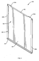
- adjustable blanking panel 100 comprises a base frame or base member 200, shown in detail in Fig. 2 , and a shield or sliding member 300, shown in detail in Fig. 3 .
- base frame 200 is generally rectangular in shape, and defines lower lip or shelf 210, rear section 220, opposing left and right side retaining members 230a and 230b, respectively, and a pair of mounting openings or holes 250a and 250b.
- Rear section 220 is generally rectangular in shape and defines opposing front and rear sides 220a and 220b, respectively, opposing top and bottom edges 220c and 220d, respectively, and opposing left and right side edges 220e and 220f, respectively.
- Lower lip or shelf 210 is preferably integrally coupled to the bottom edge 220d of rear section 220.
- Lower lip or shelf 210 is generally perpendicular to rear section 220, and extends away from the front side 220a of rear section 220.
- lower lip or shelf 210 extends along substantially the entire length of bottom edge 220d.
- lower lip or shelf 210 may extend along only a portion of the length of bottom edge 220d.
- lower lip or shelf 210 may be comprised of a plurality of non-contiguous segments.
- Opposing left and right side retaining members 230a and 230b, respectively, are substantially identical, mirror-image structures that are preferably integrally coupled to the left and right side edges 220e and 220f, respectively, of rear section 220.
- Side retaining members 230a and 230b each define a first wall, 231a and 231b, respectively, that is generally parallel to and spaced from rear section 220 and a second wall, 232a and 232b, respectively, that is generally perpendicular to rear section 220.
- Second walls 232a and 232b are preferably integrally coupled to both rear section 220 and first walls 231a and 231b, respectively.
- side retaining members 230a and 230b extend along substantially the entire height of side edges 220e and 220f, respectively. In alternate embodiments, side retaining members 230a and 230b may extend along only a portion of the height of side edges 220e and 220f. In additional embodiments, one or both of side retaining members 230a and 230b may be comprised of a plurality of non-contiguous segments.
- first and second channels 240a and 240b are configured to accommodate the left and right side edges 310e and 310f, respectively, of shield 300, as described below.
- rear section 220 further defines a pair of cut-outs or notches 260a and 260b, located proximate the top edge 220c, that are configured to facilitate the installation of base frame 200, as described below.
- Cut-out or notch 260a is located proximate left side edge 220e and cut-out or notch 260b is located proximate right side edge 260b.
- Cut-outs or notches 260a and 260b are preferably located above mounting openings or holes 250a and 250b, respectively.
- shield 300 is generally rectangular in shape, and defines panel section 310, upper lip or shelf 330, upper tabs 320a and 320b, and mounting openings or holes 340a and 340b.
- Panel section 310 is generally rectangular in shape and defines opposing front and rear sides 310a and 310b, respectively, opposing top and bottom edges 310c and 310d, respectively, and opposing left and right side edges 310e and 310f, respectively.
- Upper lip or shelf 330 is preferably integrally coupled to the top edge 314c of panel section 310. Upper lip or shelf 330 is generally perpendicular to panel section 310, and extends away from the front side 310a of panel section 310. In preferred embodiments, upper lip or shelf 330 extends along the majority of the center portion of top edge 310c.
- Upper tabs 320a and 320b are preferably integrally coupled to the top edge 300c of panel section 310 and are located on either side of upper lip or shelf 330. Upper tabs 320a and 320 b are generally perpendicular to panel section 310, but extend in the opposite direction from upper lip 330, away from the rear side 310b of panel section 310.
- the side edges 310e and 310f of panel section 310 of shield 300 are inserted into channels 240a and 240b, respectively, of base frame 200, such that base frame 200 and shield 300 are in sliding engagement with each other.
- Upper lip or shelf 330 may be grasped to allow a user to raise or lower shield 300 relative to base frame 200.
- adjustable blanking panel 100 is shown with shield 300 down or fully retracted / stowed, such that: (i) the bottom edge 310d of panel section 310 contacts and rests upon lower lip or shelf 210 of base frame 200; and (ii) upper tabs 320a and 320b of shield 300 contact and rest upon the top edge 220c of rear section 220 of base frame 200.
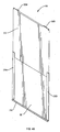
- adjustable blanking panel 100 is shown with shield 300 partially extended, such that a portion of rear section 220 is visible from the front.
- Fig. 4B adjustable blanking panel 100 is shown with shield 300 fully extended.
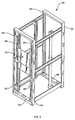
- adjustable blanking panel 100 may be mounted in enclosure 500.
- Enclosure 500 comprises front enclosure structural members 590 and 591, rear enclosure structural members 592 and 593, and horizontal enclosure structural members 594 and 595. The structural members together define an inner volume for the mounting of electrical equipment.
- Enclosure 500 further comprises rails 582 and 584, located proximate the front of enclosure 500. Rails 582 and 584 comprise a plurality of mounting openings or holes 598 along their length.
- base frame 200 at mounting holes 250a and 250b, may be removably coupled or mounted to rails 582 and 584, at a pair of mounting holes 598 via screws or other fasteners inserted through the two sets mounting holes.
- Shield 300 at mounting holes 340a and 340b, may be adjusted and similarly removably coupled or mounted to mounting rails 582 and 584, at a pair of mounting holes 598 via screws or other fasteners inserted through the two sets of mounting holes.
- adjustable blanking panel 100 may be mounted upside down.
- base frame 200 and shield 300 are constructed of bent and formed sheet metal, although this is not a limitation of the invention.
- adjustable blanking panel 100 The dimensions of a preferred embodiment of adjustable blanking panel 100 are listed below: Reference Description Preferred Dimension H1 Height of base frame 200 (Total RU) / 2 + 2/3RU H2 Height of shield 300 (Total RU) /2 + 1RU L 1 Length of base frame 200 / Length of lower lip or shelf 210 19 inches L2 Length of shield 300 18.8 inches
Description
- The invention relates to panels for use with cabinets and enclosures that house rack-mounted electrical and computer equipment. Specifically, the invention relates to height-adjustable panels for preventing the reentry of heated exhaust air into the air intake of the electrical or computer equipment.
- Electrical and computer equipment, such as computer servers, data storage devices, and power supplies, are often mounted on a rack or frame using mounting members such as shelves, rails and/or brackets. As is well known, these electronic components generate substantial heat that must be dissipated in order to maintain the devices in proper working order and prevent damage and possible failure. Most electronic device manufacturers require air of a specific temperature range to be drawn into the front of the device, passed over the internal components where the heat is exchanged, and exhausted out of the back of the device. Cabinets and enclosures, as well as the data centers or rooms that house the cabinets, are typically set up to accommodate this "front to back" air flow requirement.
- However, properly exhausting the heated air generated within the cabinets becomes increasing more difficult as more powerful equipment is installed in cabinets, and as the cabinets become more densely packed with electronic equipment. As a result, the inlet temperature of the air drawn into the devices is more likely to exceed the recommended operating range of the device. The result is an upward trend in the failure of these electronic devices. Such equipment failures are more than an inconvenience, as some failures may result in interruptions to mission critical systems and communications, such as those used for example in emergency response management, aviation and flight control, process control, and finance.
- In many cases, however, the racks or frames are not fully populated with components, resulting in vacant sections. This empty space may result in warm air from the back being drawn into the air intake at the front, which does not permit cooler air to be drawn into the electronic equipment, and may cause the equipment to overheat.
- One of the most common solutions to this problem is to attach blanking panels to the rails or brackets of the enclosure to function as a barrier and to block or fill in these vacant sections. Prior art blanking panels are typically manufactured and sold with fixed heights, ranging from one Rack Unit (RU) to four or more RUs. When the configuration of equipment inside a rack or enclosure changes, however, these fixed-sized blanking panels may need to be removed and replaced with panels of a different size. In many cases, there is no immediate further use for the panel that has been removed.
WO 2008 144 678 A1 relates to an electronic equipment enclosure having a frame structure, enclosure panels mounted on the frame structure and at least one adjustable filler panel assembly. Each adjustable filler panel assembly selectively blocks a portion of an air inlet opening to prohibit air exhausted into the duct from flowing back into the enclosure. - There is a need in the art, then, for a blanking panel that can be adjusted to different heights to allow enclosures and racks to be reconfigured without having to remove and replace a fixed-height blanking panel. In addition to the cost savings that may be realized by minimizing the number and different sizes of blanking panels that must be installed in any one cabinet or that need to be kept on hand for future use, a height-adjustable blanking panel may also reduce the amount of labor hours expended when a cabinet or enclosure is reconfigured.
- The invention disclosed herein provides height-adjustable panels and systems for preventing the circular flow and reentry of high temperature air into the air intake of the electrical or computer equipment.
- In accordance with the invention, an assembly as set forth in claim 1 and a method as set forth in claim 9 are provided. Further embodiments are inter alia disclosed in the dependent claims. In a preferred embodiment, the assembly is for use with an enclosure, where the enclosure comprises a pair of mounting rails, and each mounting rail defining a plurality of mounting holes. The assembly inter alia comprises a generally rectangular base member defining a top, a bottom, opposing left and right side channels, and a pair of mounting holes; and a generally rectangular sliding member defining a top, a bottom, opposing left and right sides, and a pair of mounting holes; where the base member mounting holes are sized and shaped to accommodate a first pair of fasteners inserted through the base member mounting holes and through a first pair of mounting rail mounting holes, to removably couple the base member to the pair of mounting rails; where the sliding member mounting holes are sized and shaped to accommodate a second pair of fasteners inserted through the sliding member mounting holes and through a second pair of mounting rail mounting holes, to removably couple the sliding member to the pair of mounting rails; and where the left and rights sides of the sliding member are located within the left and right side channels of the base member, respectively, such that the sliding member is adapted to slide relative to the base member.
- In an aspect, the top of the sliding member defines an upper lip, adapted to allow a user to raise or lower the sliding member relative to the base member. In another aspect, the bottom of the base member defines a lower lip, such that the bottom of the sliding member contacts and rests upon the lower lip when the sliding member is fully retracted. In yet another aspect, the top of the sliding member defines at least one upper tab, such that the upper tab contacts and rests upon the top of the base member when the sliding member is fully retracted.
- In an aspect, the left and right side channels are each defined by a first wall that is generally parallel to a front face of the base member, and a second wall that is generally perpendicular to the front face of the base member. In another aspect, the left and right side channels extend along the majority of the left and right sides, respectively, of the base member.
- In an aspect, the assembly comprises a base frame defining a generally rectangular rear section, and opposing left and right side retaining members; where the rear section of the base frame defines opposing front and rear sides, opposing top and bottom edges, and opposing left and right side edges; where the left and right side retaining members are coupled to the left and right side edges, respectively, of the rear section; a shield defining a generally rectangular panel section; where the panel section of the shield defines opposing front and rear sides, opposing top and bottom edges, and opposing left and right side edges; and where the left and right side edges of the panel section of the shield are located within the left and right side retaining members of the base frame, respectively, such that the shield is adapted to slide relative to the base frame.
- In an aspect, the base frame further defines a lower lip coupled to the bottom edge of the rear section of the base frame, such that the bottom edge of the panel section of the shield contacts and rests upon the lower lip when the shield is fully retracted. In another aspect, the bottom edge of the panel section of the shield contacts and rests upon the lower lip of the base frame when the shield is in a fully retracted position. In still another aspect, the shield further defines an upper lip coupled to the top edge of the panel section of the shield.
- In an aspect, the shield further defines at least one upper tab coupled to the top edge of the panel section of the shield, such that the upper tab contacts and rests upon the top edge of the rear panel of the base frame when the shield is in a fully retracted position. In another aspect, the base frame further defines one or more mounting holes proximate the top edge of the rear panel of the base frame, for attaching the base frame to the pair of mounting rails. In still another aspect, the shield further defines one or mounting holes proximate the top edge of the panel section of the shield, for attaching the shield to the pair of mounting rails.
- In an aspect, the left and right side retaining members are each defined by a first wall that is generally parallel to and spaced from the front side of the rear panel of the base frame and a second wall that is generally perpendicular to the front side of the rear panel of the base frame. In another aspect, the second walls of each of the retaining members are coupled to their corresponding front wall and to the rear section of the base frame. In still another aspect, the left and right side retaining members extend along the majority of the left and right side edges, respectively, of the rear panel of the base frame.
- In an additional preferred embodiment, an enclosure for mounting electronic equipment comprises a plurality of vertical structural members defining an inner volume between the structural members; a pair of mounting rails, each mounting rail coupled to one of the vertical structural members; and an assembly coupled to the pair of mounting rails, where the assembly comprises a generally rectangular base member defining a top, a bottom, and opposing left and right side channels and a generally rectangular sliding member defining a top, a bottom, and opposing left and right sides; and where the left and rights sides of the sliding member are located within the left and right side channels, respectively, such that the sliding member is adapted to slide relative to the base member to adjustably allow access to the inner volume.
- In an aspect, the base member further defines a pair of mounting holes; the sliding member further defines a pair of mounting holes; each mounting rail defines a plurality of mounting holes; the base member mounting holes are sized and shaped to accommodate a first pair of fasteners inserted through the base member mounting holes and through a first pair of mounting rail mounting holes, to removably couple the base member to the pair of mounting rails; and the sliding member mounting holes are sized and shaped to accommodate a second pair of fasteners inserted through the sliding member mounting holes and through a second pair of mounting rail mounting holes, to removably couple the sliding member to the pair of mounting rails.
- The method is for adjustably allowing access to an inner volume of an enclosure for mounting electronic equipment and inter alia comprises providing an enclosure comprises a plurality of vertical structural members defining an inner volume between the structural members, and a pair of mounting rails, where each of the mounting rails defines a plurality of mounting holes and is coupled to at least one of the vertical structural members; providing an assembly comprising a generally rectangular base member defining a top, a bottom, opposing left and right side channels, and a pair of mounting holes, and a generally rectangular sliding member defining a top, a bottom, and opposing left and right sides; coupling the base member to the pair of mounting rails by inserting a first pair of fasteners through the base member mounting holes and through a first pair of mounting rail mounting holes; inserting the left and rights sides of the sliding member into the left and right side channels of the base member; and sliding the sliding member relative to the base member to adjust access to the inner volume of the enclosure.
- In an aspect, the sliding member further defines a pair of mounting holes, and the method further comprises the step of coupling the sliding member to the pair of mounting rails by inserting a second pair of fasteners through the sliding member mounting holes and through a second pair of mounting rail mounting holes.
- Embodiments of the invention may provide one or more advantages, including:
- Airflow Management - allows cooled air to be utilized where needed, and prevents heated air from recirculating and damaging equipment.
- Reversible Application - can be installed either top-up or bottom-up.
- Adjustable Application - can be installed within multiple mounting settings and rail positions.
- Modular Application - can be installed with or without various features and settings as well as in multiple arrangements and configurations.
- Space/Size Adaptability - can be adapted for use with electronic equipment in a range of sizes and heights.
- Material Selection - can be constructed in multiple materials to meet different cost and environment requirements.
- The foregoing and other objects, features and advantages of the invention will be apparent from the following more particular description of preferred embodiments of the invention, as illustrated in the accompanying drawings in which like reference characters refer to the same parts throughout the different views. The drawings are not necessarily to scale, emphasis instead being placed upon illustrating the principles of the invention.
-
Fig. 1 is a perspective view of an adjustable blanking panel, according to a preferred embodiment of the invention; -
Fig. 2 is a perspective view of a base frame of the adjustable blanking panel ofFig. 1 ; -
Fig. 3 is a perspective view of a shield of the adjustable blanking panel ofFig. 1 ; -
Figs. 4A and4B illustrate a preferred manner in which the shield of the adjustable blanking panel ofFig. 1 may be adjusted relative to the base frame ofFig. 1 ; and -
Fig. 5 illustrates a preferred manner in which the adjustable blanking panel ofFig. 1 may be mounted in an enclosure. - In a preferred embodiment, and as shown in
Fig. 1 ,adjustable blanking panel 100 comprises a base frame orbase member 200, shown in detail inFig. 2 , and a shield or slidingmember 300, shown in detail inFig. 3 . - With further reference to
Fig. 2 , in a preferredembodiment base frame 200 is generally rectangular in shape, and defines lower lip orshelf 210,rear section 220, opposing left and rightside retaining members holes -
Rear section 220 is generally rectangular in shape and defines opposing front andrear sides bottom edges 220c and 220d, respectively, and opposing left and right side edges 220e and 220f, respectively. - Lower lip or
shelf 210 is preferably integrally coupled to thebottom edge 220d ofrear section 220. Lower lip orshelf 210 is generally perpendicular torear section 220, and extends away from thefront side 220a ofrear section 220. In preferred embodiments, lower lip orshelf 210 extends along substantially the entire length ofbottom edge 220d. In alternate embodiments, lower lip orshelf 210 may extend along only a portion of the length ofbottom edge 220d. In additional embodiments, lower lip orshelf 210 may be comprised of a plurality of non-contiguous segments. - Opposing left and right
side retaining members rear section 220.Side retaining members rear section 220 and a second wall, 232a and 232b, respectively, that is generally perpendicular torear section 220.Second walls rear section 220 andfirst walls - In preferred embodiments,
side retaining members side edges side retaining members side edges side retaining members - As is shown in
Fig. 2 , the arrangement offirst wall 231a,second wall 232a andfront side 220a ofrear section 220 forms afirst channel 240a, and the arrangement offirst wall 231 b,second wall 232b andfront side 220a ofrear section 220 forms asecond channel 240b. In preferred embodiments, first andsecond channels shield 300, as described below. - In preferred embodiments,
rear section 220 further defines a pair of cut-outs ornotches base frame 200, as described below. Cut-out or notch 260a is located proximateleft side edge 220e and cut-out ornotch 260b is located proximateright side edge 260b. Cut-outs ornotches holes - With further reference to
Fig. 3 , in a preferred embodiment,shield 300 is generally rectangular in shape, and definespanel section 310, upper lip orshelf 330,upper tabs holes -
Panel section 310 is generally rectangular in shape and defines opposing front andrear sides bottom edges 310c and 310d, respectively, and opposing left and right side edges 310e and 310f, respectively. - Upper lip or
shelf 330 is preferably integrally coupled to the top edge 314c ofpanel section 310. Upper lip orshelf 330 is generally perpendicular topanel section 310, and extends away from thefront side 310a ofpanel section 310. In preferred embodiments, upper lip orshelf 330 extends along the majority of the center portion of top edge 310c. -
Upper tabs panel section 310 and are located on either side of upper lip orshelf 330.Upper tabs panel section 310, but extend in the opposite direction fromupper lip 330, away from therear side 310b ofpanel section 310. - In a preferred method of use, as shown in
Figs. 1 ,4A and4B , the side edges 310e and 310f ofpanel section 310 ofshield 300 are inserted intochannels base frame 200, such thatbase frame 200 and shield 300 are in sliding engagement with each other. Upper lip orshelf 330 may be grasped to allow a user to raise orlower shield 300 relative tobase frame 200. - In
Fig. 1 , in one preferred method of use,adjustable blanking panel 100 is shown withshield 300 down or fully retracted / stowed, such that: (i) thebottom edge 310d ofpanel section 310 contacts and rests upon lower lip orshelf 210 ofbase frame 200; and (ii)upper tabs shield 300 contact and rest upon the top edge 220c ofrear section 220 ofbase frame 200. InFig. 4A ,adjustable blanking panel 100 is shown withshield 300 partially extended, such that a portion ofrear section 220 is visible from the front. InFig. 4B ,adjustable blanking panel 100 is shown withshield 300 fully extended. - As shown in
Fig. 5 ,adjustable blanking panel 100 may be mounted inenclosure 500.Enclosure 500 comprises front enclosurestructural members structural members structural members Enclosure 500 further comprisesrails enclosure 500.Rails holes 598 along their length. - In a preferred embodiment,
base frame 200, at mountingholes rails holes 598 via screws or other fasteners inserted through the two sets mounting holes.Shield 300, at mountingholes rails holes 598 via screws or other fasteners inserted through the two sets of mounting holes. Note that, in alternate preferred embodiments,adjustable blanking panel 100 may be mounted upside down. - In a preferred embodiment,
base frame 200 and shield 300 are constructed of bent and formed sheet metal, although this is not a limitation of the invention. - The dimensions of a preferred embodiment of
adjustable blanking panel 100 are listed below:Reference Description Preferred Dimension H1 Height of base frame 200 (Total RU) / 2 + 2/3RU H2 Height of shield 300 (Total RU) /2 + 1RU L 1 Length of base frame 200 / Length of lower lip orshelf 21019 inches L2 Length of shield 30018.8 inches - The particular construction, materials and dimensions described herein are not limitations of the invention, as other constructions can accomplish the invention described herein.
- Although specific features of the invention are shown in some figures and not others, this is for convenience only, as some features may be combined with any or all of the other features in accordance with the invention.
- Recitation ranges of values herein are merely intended to serve as a shorthand method of referring individually to each separate value falling within the range, unless otherwise indicated herein, and each separate value is incorporated into the specification as if it were individually recited herein.
- The use of any and all examples, or exemplary language (e.g., "such as") provided herein, is intended merely to better illustrate the invention and does not pose a limitation on the scope of the invention.
- A variety of modifications to the embodiments described herein will be apparent to those skilled in the art from the disclosure provided herein. Thus the invention may be embodied in other specific forms without departing from the scope of the appended claims.
Claims (11)
- An assembly (100) for use with an enclosure, the enclosure comprising a pair of mounting rails (582, 584), each mounting rail defining a plurality of mounting holes (598), the assembly (100) comprising:a generally rectangular base member (200) defining a rear section (220) having a top (220c) and a bottom (220d), and opposing left and right side channels (240a, 240b);where the rear section (220) of the generally rectangular base member (200) includes at least two mounting holes (250a, 250b);a generally rectangular sliding member (300) defining a panel section (310) having a top (310c), a bottom (310d), and opposing left and right sides (310e, 310f);where the panel section (310) of the generally rectangular sliding member (300) includes at least two mounting holes (340a, 340b);where the base member mounting holes (250a, 250b) are sized and shaped to accommodate a first pair of fasteners inserted through the base member mounting holes (250a, 250b) and through a first pair of mounting rail mounting holes (598), to removably couple the base member to the pair of mounting rails (582, 584);where the sliding member mounting holes (340a, 340b) are sized and shaped to accommodate a second pair of fasteners inserted through the sliding member mounting holes (340a, 340b) and through a second pair of mounting rail mounting holes (598), to removably couple the sliding member to the pair of mounting rails (582, 584); andwhere the left and right sides (310e, 310f) of the panel section (310) are located within the left and right side channels (240a, 240b) of the base member (200), respectively, such that the sliding member (300) is adapted to slide relative to the base member (200).
- The assembly (100) of claim 1, where the sliding member (300) defines an upper lip (330) at the top of the panel section (310), adapted to allow a user to raise or lower the sliding member (300) relative to the base member (200).
- The assembly (100) of claim 1, where the base member (200) defines a lower lip (210), such that the bottom (310d) of the panel section (310) of the sliding member (300) contacts and rests upon the lower lip (210) when the sliding member (300) is fully retracted.
- The assembly (100) of claim 1, where the sliding member defines at least one upper tab at the top (310d) of the panel section (310), such that the upper tab (320a, 320b) contacts and rests upon the top (220c) of the rear section (220) of base member (200) when the sliding member (300) is fully retracted.
- The assembly (100) of claim 1, where the left and right side channels (240a, 240b) are each defined by a first wall (231a, 231b) that is generally parallel to a front face of the rear section (220) of the base member (200), and a second wall (232a, 232b) that is generally perpendicular to the front face of the rear section (220) of the base member (200).
- The assembly (100) of claim 1, where the left and right side channels (240a, 240b) extend along the majority of the left and right sides(220e, 220f), respectively, of the rear section (220) of the base member (200).
- The assembly (100) of claim 1, comprising an enclosure (500) having:a plurality of vertical structural members (590, 591, 593, 594) defining an inner volume between the structural members; anda pair of mounting rails (582, 584), each mounting rail coupled to one of the vertical structural members (590, 591).
- The assembly (100) of claim 7, where each mounting rail (582, 584) defines a plurality of mounting holes (598).
- A method of adjustably allowing access to an inner volume of an enclosure (500) for mounting electronic equipment, comprising:providing an enclosure (500) comprisinga plurality of vertical structural members (590, 591, 593, 594) defining an inner volume between the structural members(590, 591, 593, 594), anda pair of mounting rails (582, 584), where each of the mounting rails (582, 584) defines a plurality of mounting holes (598) and is coupled to at least one of the vertical structural members(590, 591);providing an assembly (100) comprisinga generally rectangular base member (200) defining a rear section (220) having a top (220c) and a bottom (220d), and opposing left and right side channels (240a, 240b); where the rear section (220) of the generally rectangular base member (200) includes at least two mounting holes (250a, 250b);a generally rectangular sliding member (300) defining a panel section (310) having a top (310c) and a bottom (310d), and opposing left and right sides (310e, 310f);where the panel section (310) of the generally rectangular sliding member (300) includes at least two mounting holes (340a, 340b);coupling the base member (200) to the pair of mounting rails (582, 584) by inserting a first pair of fasteners through the base member mounting holes (250a, 250b) and through a first pair of mounting rail mounting holes (598);inserting the left and rights sides (310e, 310f) of panel section (310) of the sliding member (300) into the left and right side channels (240a, 240b) of the base member (200); andsliding the sliding member (300) relative to the base member (200) to adjust access to the inner volume of the enclosure (500).
- The method of claim 9, further comprising the step of coupling the sliding member (300) to the pair of mounting rails (582, 584) by inserting a second pair of fasteners through the sliding member mounting holes (340a, 340b) and through a second pair of mounting rail mounting holes (598).
- The assembly of claim 1, wherein the sliding member (300), when adapted to slide relative to the base member (200), is adapted to be vertically positioned, substantially parallel to the pair of mounting rails (582, 584), between a first height relative to the base member (200) and a second height relative to the base member (300) to adjust a flow of air into the enclosure (500).
Applications Claiming Priority (2)
| Application Number | Priority Date | Filing Date | Title |
|---|---|---|---|
| US29630910P | 2010-01-19 | 2010-01-19 | |
| PCT/US2011/021084 WO2011090874A1 (en) | 2010-01-19 | 2011-01-13 | Adjustable blanking panel |
Publications (3)
| Publication Number | Publication Date |
|---|---|
| EP2526748A1 EP2526748A1 (en) | 2012-11-28 |
| EP2526748A4 EP2526748A4 (en) | 2014-12-10 |
| EP2526748B1 true EP2526748B1 (en) | 2016-08-17 |
Family
ID=44277116
Family Applications (1)
| Application Number | Title | Priority Date | Filing Date |
|---|---|---|---|
| EP11735010.8A Active EP2526748B1 (en) | 2010-01-19 | 2011-01-13 | Adjustable blanking panel |
Country Status (5)
| Country | Link |
|---|---|
| US (1) | US8459756B2 (en) |
| EP (1) | EP2526748B1 (en) |
| CN (1) | CN102934534A (en) |
| AU (1) | AU2011207741B2 (en) |
| WO (1) | WO2011090874A1 (en) |
Families Citing this family (37)
| Publication number | Priority date | Publication date | Assignee | Title |
|---|---|---|---|---|
| US8622227B2 (en) * | 2007-01-16 | 2014-01-07 | Fasteners For Retail, Inc. | Merchandise security system |
| US8152006B2 (en) | 2007-01-16 | 2012-04-10 | Fasteners For Retail, Inc. | Merchandise security system |
| US8628158B2 (en) | 2010-05-13 | 2014-01-14 | Panduit Corp. | Aisle containment system |
| US8787023B2 (en) * | 2010-09-10 | 2014-07-22 | Chatsworth Products, Inc. | Rail mounting clamp for electronic equipment enclosure |
| US8901438B2 (en) | 2010-09-10 | 2014-12-02 | Chatsworth Products, Inc. | Electronic equipment cabinet structure |
| EP2429272A2 (en) | 2010-09-10 | 2012-03-14 | Chatsworth Products, Inc. | Cable pass-through panel for electronic equipment enclosure |
| US9560777B2 (en) | 2010-11-08 | 2017-01-31 | Chatsworth Products, Inc. | Door closer mechanism for hot/cold aisle air containment room |
| US9313927B2 (en) | 2010-11-08 | 2016-04-12 | Chatsworth Products, Inc. | Header panel assembly for preventing air circulation above electronic equipment enclosure |
| US9955616B2 (en) | 2010-11-08 | 2018-04-24 | Chatsworth Products, Inc. | Header panel assembly for preventing air circulation above electronic equipment enclosure |
| US9585266B2 (en) | 2010-11-08 | 2017-02-28 | Chatsworth Products, Inc. | Header panel assembly for preventing air circulation above electronic equipment enclosure |
| EP2453538B1 (en) * | 2010-11-10 | 2016-06-15 | Abb Ag | Electrical switch and/or distribution cabinet |
| US8915286B2 (en) | 2010-12-17 | 2014-12-23 | Panduit Corp. | Roller shade filler panel |
| WO2012135136A2 (en) * | 2011-03-25 | 2012-10-04 | Compuspace, Lc | Filler panels and systems |
| US20120326584A1 (en) * | 2011-06-21 | 2012-12-27 | Johnson Michael E | Water cooler cover having adjustable and relocatable openings |
| US11246231B2 (en) | 2012-02-10 | 2022-02-08 | Chatsworth Products, Inc. | Door closer mechanism for hot/cold aisle air containment room |
| US8857120B2 (en) | 2012-04-19 | 2014-10-14 | Panduit Corp. | Ceiling supported cold aisle containment system |
| US8925739B2 (en) * | 2012-07-26 | 2015-01-06 | Lenovo Enterprise Solutions (Singapore) Pte. Ltd. | High-capacity computer rack with rear-accessible side bays |
| US10076064B2 (en) * | 2012-11-28 | 2018-09-11 | Eaton Intelligent Power Limited | Housing having configurable airflow exhaust |
| US20140196394A1 (en) | 2013-01-11 | 2014-07-17 | Chatsworth Products, Inc. | Modular thermal isolation barrier for data processing equipment structure |
| CN104105367A (en) * | 2013-04-09 | 2014-10-15 | 鸿富锦精密工业(深圳)有限公司 | Cabinet-type server and wind shielding devices thereof |
| US20140317902A1 (en) * | 2013-04-30 | 2014-10-30 | Calvary Applied Technologies, LLC | Rack door transition kit with universal bracket |
| EP2830170A1 (en) * | 2013-07-23 | 2015-01-28 | ABB S.p.A. | A mounting bracket for a cabinet of an electrical switchboard |
| GB2517946A (en) * | 2013-09-05 | 2015-03-11 | Ibm | Adjustable blanking panel for datacentre racks |
| US9351427B2 (en) | 2013-12-17 | 2016-05-24 | Chatsworth Products, Inc. | Electronic equipment enclosure |
| US9255417B2 (en) | 2014-03-12 | 2016-02-09 | Panduit Corp. | Independent aisle containment system |
| US10104798B2 (en) | 2014-03-25 | 2018-10-16 | Hubbell Incorporated | Telescoping security enclosure |
| DE102014107168B4 (en) * | 2014-05-21 | 2016-01-07 | Knürr GmbH | Frame for electronics or network cabinets |
| CN104456847B (en) * | 2014-11-21 | 2017-12-29 | 北京百度网讯科技有限公司 | A kind of method for closing cold passage |
| US9992557B2 (en) | 2015-11-19 | 2018-06-05 | Hubbell Incorporated | Rack mountable security enclosures |
| US9949408B2 (en) | 2016-05-27 | 2018-04-17 | Cisco Technology, Inc. | Blank card with scalable airflow impedance for electronic enclosures |
| US10455744B2 (en) * | 2016-07-31 | 2019-10-22 | Ilone Grinberg | Extendible barrier |
| US10271451B2 (en) * | 2017-06-30 | 2019-04-23 | Mastercard International Incorporated | Mounting assemblies for supporting card readers in electronic equipment racks, and related methods |
| CN109843017B (en) * | 2017-11-29 | 2020-10-02 | 联想企业解决方案(新加坡)有限公司 | Server rack door access |
| USD904327S1 (en) * | 2018-04-10 | 2020-12-08 | Fmr Llc | Freestanding blanking panel |
| CN108770275B (en) * | 2018-05-31 | 2020-10-27 | 合肥开关厂有限公司 | Mining explosion-proof and intrinsically safe industrial computer rack |
| US11432429B2 (en) | 2020-05-05 | 2022-08-30 | Hoffman Enclosures Inc. | Adjustable barrier for enclosures |
| US20230097307A1 (en) * | 2021-09-17 | 2023-03-30 | Microsoft Technology Licensing, Llc | Airflow blocking device for use in server racks |
Family Cites Families (24)
| Publication number | Priority date | Publication date | Assignee | Title |
|---|---|---|---|---|
| US3773399A (en) * | 1972-03-27 | 1973-11-20 | Whirlpool Co | Front panel construction for refuse compactor drawer |
| US3765344A (en) * | 1972-05-15 | 1973-10-16 | Hirsh Co | Telescoping shelf assembly |
| US3757934A (en) * | 1972-05-15 | 1973-09-11 | Taub R | Telescoping display assembly |
| US3851938A (en) * | 1973-09-24 | 1974-12-03 | T Mccowan | Storage device |
| US4500146A (en) * | 1983-08-01 | 1985-02-19 | Sioux Technology, Inc. | Locker shelf assembly |
| US4713949A (en) * | 1985-10-03 | 1987-12-22 | Top Shelf Company, Inc. | Shelf system for appliance |
| IT230672Y1 (en) * | 1993-10-26 | 1999-06-09 | Cms Costr Meccan Sestesi Srl | CABINET STRUCTURE, FOR ELECTRIC OR ELECTRONIC EQUIPMENT, WITH VARIABLE DIMENSIONS |
| US5889648A (en) * | 1997-07-25 | 1999-03-30 | Storage Technology Corporation | Seismic cabinet |
| US6278606B1 (en) * | 1999-01-06 | 2001-08-21 | Dell Usa, L.P. | Computer and method for EMI containment in a computer |
| US6496364B1 (en) * | 2001-01-12 | 2002-12-17 | Crystal Group Inc. | Upgradeable system and method for connecting a 1U personal computer |
| US6758353B2 (en) * | 2001-04-19 | 2004-07-06 | David Orr | Blank panel for rack units |
| US6629614B2 (en) * | 2001-05-01 | 2003-10-07 | Nortel Networks Limited | Mounting for telecommunications equipment |
| US7506768B2 (en) * | 2004-10-15 | 2009-03-24 | American Power Conversion Corporation | Blanking panel for equipment rack or enclosure |
| US7645001B2 (en) * | 2005-02-24 | 2010-01-12 | Industrial Wire Products, Inc. | Locker shelf |
| US7438638B2 (en) * | 2005-10-10 | 2008-10-21 | Chatsworth Products, Inc. | Ratio of open area to closed area in panels for electronic equipment enclosures |
| US7862410B2 (en) * | 2006-01-20 | 2011-01-04 | American Power Conversion Corporation | Air removal unit |
| US20080203863A1 (en) * | 2007-02-28 | 2008-08-28 | Beirne John J | Gaming Apparatus Support Base |
| US7764495B2 (en) * | 2007-04-30 | 2010-07-27 | Adc Telecommunications, Inc. | Telecommunication cabinet with airflow ducting |
| US7746637B2 (en) * | 2007-05-17 | 2010-06-29 | Chatsworth Products, Inc. | Electronic equipment enclosure with exhaust air duct and adjustable filler panel assemblies |
| US7987799B2 (en) * | 2007-06-12 | 2011-08-02 | Hoffman Enclosures, Inc. | Adjustable shelf |
| DK2193248T3 (en) * | 2007-08-21 | 2018-05-07 | Compuspace Lc | SERVERRACK DINNER PANEL AND SYSTEM |
| SE535066C2 (en) * | 2008-01-07 | 2012-04-03 | Chatsworth Prod Inc | Vertical cable management device |
| US7988244B2 (en) * | 2008-01-17 | 2011-08-02 | Haws Jr Joe D | Modular merchandise pod |
| EP2205054A1 (en) * | 2009-01-05 | 2010-07-07 | Chatsworth Product, INC. | Electronic equipment enclosure with side-to-side airflow control system |
-
2011
- 2011-01-13 WO PCT/US2011/021084 patent/WO2011090874A1/en active Application Filing
- 2011-01-13 CN CN2011800144765A patent/CN102934534A/en active Pending
- 2011-01-13 EP EP11735010.8A patent/EP2526748B1/en active Active
- 2011-01-13 US US13/005,811 patent/US8459756B2/en active Active
- 2011-01-13 AU AU2011207741A patent/AU2011207741B2/en not_active Ceased
Also Published As
| Publication number | Publication date |
|---|---|
| AU2011207741B2 (en) | 2014-01-09 |
| EP2526748A1 (en) | 2012-11-28 |
| EP2526748A4 (en) | 2014-12-10 |
| AU2011207741A1 (en) | 2012-08-16 |
| CN102934534A (en) | 2013-02-13 |
| US20110175505A1 (en) | 2011-07-21 |
| WO2011090874A1 (en) | 2011-07-28 |
| US8459756B2 (en) | 2013-06-11 |
Similar Documents
| Publication | Publication Date | Title |
|---|---|---|
| EP2526748B1 (en) | Adjustable blanking panel | |
| EP2298051B1 (en) | Rack mounted cooling unit | |
| US20120049706A1 (en) | Air Flow Management Enclosure | |
| US8355246B2 (en) | Modular air management devices | |
| US6516954B2 (en) | Equipment rack with integral HVAC and power distribution features | |
| US8405984B2 (en) | Exhaust air duct with adjustable filler panel assemblies | |
| US9615488B1 (en) | Datacenter aisle containment structure | |
| US8310832B2 (en) | Side-exhaust cooling system for rack mounted equipment | |
| EP2342962B1 (en) | Rear door heat exchanger transition frame | |
| US6927976B1 (en) | Air baffle for managing cooling air re-circulation in an electronic system | |
| US20080217962A1 (en) | Apparatus and method for configuring a dual rack-mountable chassis | |
| EP2449866A2 (en) | Adjustable vertical exhaust duct | |
| EP2410828B1 (en) | Systems and methods for managing heat generated by electronic equipment in an electronic equipment enclosure | |
| WO2009103090A2 (en) | Air directing device | |
| US10349553B2 (en) | Adjustable rack for electronics cabinet | |
| US20050157472A1 (en) | Slot filler with capability to control electronic cooling air recirculation | |
| EP2638607B1 (en) | Equipment-rack power distribution system with cooling | |
| EP3005851B1 (en) | Housing having configurable airflow exhaust | |
| CN213755396U (en) | Cabinet for installing data security terminal | |
| WO2001011446A2 (en) | Computer casing |
Legal Events
| Date | Code | Title | Description |
|---|---|---|---|
| PUAI | Public reference made under article 153(3) epc to a published international application that has entered the european phase |
Free format text: ORIGINAL CODE: 0009012 |
|
| 17P | Request for examination filed |
Effective date: 20120719 |
|
| AK | Designated contracting states |
Kind code of ref document: A1 Designated state(s): AL AT BE BG CH CY CZ DE DK EE ES FI FR GB GR HR HU IE IS IT LI LT LU LV MC MK MT NL NO PL PT RO RS SE SI SK SM TR |
|
| DAX | Request for extension of the european patent (deleted) | ||
| A4 | Supplementary search report drawn up and despatched |
Effective date: 20141110 |
|
| RIC1 | Information provided on ipc code assigned before grant |
Ipc: H05K 7/20 20060101AFI20141104BHEP |
|
| GRAP | Despatch of communication of intention to grant a patent |
Free format text: ORIGINAL CODE: EPIDOSNIGR1 |
|
| INTG | Intention to grant announced |
Effective date: 20160217 |
|
| GRAS | Grant fee paid |
Free format text: ORIGINAL CODE: EPIDOSNIGR3 |
|
| GRAA | (expected) grant |
Free format text: ORIGINAL CODE: 0009210 |
|
| AK | Designated contracting states |
Kind code of ref document: B1 Designated state(s): AL AT BE BG CH CY CZ DE DK EE ES FI FR GB GR HR HU IE IS IT LI LT LU LV MC MK MT NL NO PL PT RO RS SE SI SK SM TR |
|
| REG | Reference to a national code |
Ref country code: GB Ref legal event code: FG4D |
|
| REG | Reference to a national code |
Ref country code: CH Ref legal event code: EP |
|
| REG | Reference to a national code |
Ref country code: IE Ref legal event code: FG4D |
|
| REG | Reference to a national code |
Ref country code: AT Ref legal event code: REF Ref document number: 822176 Country of ref document: AT Kind code of ref document: T Effective date: 20160915 |
|
| REG | Reference to a national code |
Ref country code: DE Ref legal event code: R096 Ref document number: 602011029327 Country of ref document: DE |
|
| REG | Reference to a national code |
Ref country code: NL Ref legal event code: FP |
|
| REG | Reference to a national code |
Ref country code: LT Ref legal event code: MG4D |
|
| REG | Reference to a national code |
Ref country code: FR Ref legal event code: PLFP Year of fee payment: 7 |
|
| REG | Reference to a national code |
Ref country code: AT Ref legal event code: MK05 Ref document number: 822176 Country of ref document: AT Kind code of ref document: T Effective date: 20160817 |
|
| PG25 | Lapsed in a contracting state [announced via postgrant information from national office to epo] |
Ref country code: HR Free format text: LAPSE BECAUSE OF FAILURE TO SUBMIT A TRANSLATION OF THE DESCRIPTION OR TO PAY THE FEE WITHIN THE PRESCRIBED TIME-LIMIT Effective date: 20160817 Ref country code: LT Free format text: LAPSE BECAUSE OF FAILURE TO SUBMIT A TRANSLATION OF THE DESCRIPTION OR TO PAY THE FEE WITHIN THE PRESCRIBED TIME-LIMIT Effective date: 20160817 Ref country code: FI Free format text: LAPSE BECAUSE OF FAILURE TO SUBMIT A TRANSLATION OF THE DESCRIPTION OR TO PAY THE FEE WITHIN THE PRESCRIBED TIME-LIMIT Effective date: 20160817 Ref country code: IT Free format text: LAPSE BECAUSE OF FAILURE TO SUBMIT A TRANSLATION OF THE DESCRIPTION OR TO PAY THE FEE WITHIN THE PRESCRIBED TIME-LIMIT Effective date: 20160817 Ref country code: NO Free format text: LAPSE BECAUSE OF FAILURE TO SUBMIT A TRANSLATION OF THE DESCRIPTION OR TO PAY THE FEE WITHIN THE PRESCRIBED TIME-LIMIT Effective date: 20161117 Ref country code: RS Free format text: LAPSE BECAUSE OF FAILURE TO SUBMIT A TRANSLATION OF THE DESCRIPTION OR TO PAY THE FEE WITHIN THE PRESCRIBED TIME-LIMIT Effective date: 20160817 |
|
| PG25 | Lapsed in a contracting state [announced via postgrant information from national office to epo] |
Ref country code: AT Free format text: LAPSE BECAUSE OF FAILURE TO SUBMIT A TRANSLATION OF THE DESCRIPTION OR TO PAY THE FEE WITHIN THE PRESCRIBED TIME-LIMIT Effective date: 20160817 Ref country code: LV Free format text: LAPSE BECAUSE OF FAILURE TO SUBMIT A TRANSLATION OF THE DESCRIPTION OR TO PAY THE FEE WITHIN THE PRESCRIBED TIME-LIMIT Effective date: 20160817 Ref country code: PT Free format text: LAPSE BECAUSE OF FAILURE TO SUBMIT A TRANSLATION OF THE DESCRIPTION OR TO PAY THE FEE WITHIN THE PRESCRIBED TIME-LIMIT Effective date: 20161219 Ref country code: PL Free format text: LAPSE BECAUSE OF FAILURE TO SUBMIT A TRANSLATION OF THE DESCRIPTION OR TO PAY THE FEE WITHIN THE PRESCRIBED TIME-LIMIT Effective date: 20160817 Ref country code: GR Free format text: LAPSE BECAUSE OF FAILURE TO SUBMIT A TRANSLATION OF THE DESCRIPTION OR TO PAY THE FEE WITHIN THE PRESCRIBED TIME-LIMIT Effective date: 20161118 Ref country code: ES Free format text: LAPSE BECAUSE OF FAILURE TO SUBMIT A TRANSLATION OF THE DESCRIPTION OR TO PAY THE FEE WITHIN THE PRESCRIBED TIME-LIMIT Effective date: 20160817 Ref country code: SE Free format text: LAPSE BECAUSE OF FAILURE TO SUBMIT A TRANSLATION OF THE DESCRIPTION OR TO PAY THE FEE WITHIN THE PRESCRIBED TIME-LIMIT Effective date: 20160817 |
|
| PG25 | Lapsed in a contracting state [announced via postgrant information from national office to epo] |
Ref country code: EE Free format text: LAPSE BECAUSE OF FAILURE TO SUBMIT A TRANSLATION OF THE DESCRIPTION OR TO PAY THE FEE WITHIN THE PRESCRIBED TIME-LIMIT Effective date: 20160817 Ref country code: RO Free format text: LAPSE BECAUSE OF FAILURE TO SUBMIT A TRANSLATION OF THE DESCRIPTION OR TO PAY THE FEE WITHIN THE PRESCRIBED TIME-LIMIT Effective date: 20160817 |
|
| REG | Reference to a national code |
Ref country code: DE Ref legal event code: R097 Ref document number: 602011029327 Country of ref document: DE |
|
| PG25 | Lapsed in a contracting state [announced via postgrant information from national office to epo] |
Ref country code: BG Free format text: LAPSE BECAUSE OF FAILURE TO SUBMIT A TRANSLATION OF THE DESCRIPTION OR TO PAY THE FEE WITHIN THE PRESCRIBED TIME-LIMIT Effective date: 20161117 Ref country code: SK Free format text: LAPSE BECAUSE OF FAILURE TO SUBMIT A TRANSLATION OF THE DESCRIPTION OR TO PAY THE FEE WITHIN THE PRESCRIBED TIME-LIMIT Effective date: 20160817 Ref country code: BE Free format text: LAPSE BECAUSE OF FAILURE TO SUBMIT A TRANSLATION OF THE DESCRIPTION OR TO PAY THE FEE WITHIN THE PRESCRIBED TIME-LIMIT Effective date: 20160817 Ref country code: DK Free format text: LAPSE BECAUSE OF FAILURE TO SUBMIT A TRANSLATION OF THE DESCRIPTION OR TO PAY THE FEE WITHIN THE PRESCRIBED TIME-LIMIT Effective date: 20160817 Ref country code: CZ Free format text: LAPSE BECAUSE OF FAILURE TO SUBMIT A TRANSLATION OF THE DESCRIPTION OR TO PAY THE FEE WITHIN THE PRESCRIBED TIME-LIMIT Effective date: 20160817 Ref country code: SM Free format text: LAPSE BECAUSE OF FAILURE TO SUBMIT A TRANSLATION OF THE DESCRIPTION OR TO PAY THE FEE WITHIN THE PRESCRIBED TIME-LIMIT Effective date: 20160817 |
|
| PLBE | No opposition filed within time limit |
Free format text: ORIGINAL CODE: 0009261 |
|
| STAA | Information on the status of an ep patent application or granted ep patent |
Free format text: STATUS: NO OPPOSITION FILED WITHIN TIME LIMIT |
|
| 26N | No opposition filed |
Effective date: 20170518 |
|
| REG | Reference to a national code |
Ref country code: DE Ref legal event code: R119 Ref document number: 602011029327 Country of ref document: DE |
|
| PG25 | Lapsed in a contracting state [announced via postgrant information from national office to epo] |
Ref country code: SI Free format text: LAPSE BECAUSE OF FAILURE TO SUBMIT A TRANSLATION OF THE DESCRIPTION OR TO PAY THE FEE WITHIN THE PRESCRIBED TIME-LIMIT Effective date: 20160817 |
|
| REG | Reference to a national code |
Ref country code: CH Ref legal event code: PL |
|
| GBPC | Gb: european patent ceased through non-payment of renewal fee |
Effective date: 20170113 |
|
| PG25 | Lapsed in a contracting state [announced via postgrant information from national office to epo] |
Ref country code: MC Free format text: LAPSE BECAUSE OF FAILURE TO SUBMIT A TRANSLATION OF THE DESCRIPTION OR TO PAY THE FEE WITHIN THE PRESCRIBED TIME-LIMIT Effective date: 20160817 |
|
| PG25 | Lapsed in a contracting state [announced via postgrant information from national office to epo] |
Ref country code: LI Free format text: LAPSE BECAUSE OF NON-PAYMENT OF DUE FEES Effective date: 20170131 Ref country code: CH Free format text: LAPSE BECAUSE OF NON-PAYMENT OF DUE FEES Effective date: 20170131 |
|
| PG25 | Lapsed in a contracting state [announced via postgrant information from national office to epo] |
Ref country code: DE Free format text: LAPSE BECAUSE OF NON-PAYMENT OF DUE FEES Effective date: 20170801 Ref country code: LU Free format text: LAPSE BECAUSE OF NON-PAYMENT OF DUE FEES Effective date: 20170113 Ref country code: GB Free format text: LAPSE BECAUSE OF NON-PAYMENT OF DUE FEES Effective date: 20170113 |
|
| REG | Reference to a national code |
Ref country code: FR Ref legal event code: PLFP Year of fee payment: 8 |
|
| PG25 | Lapsed in a contracting state [announced via postgrant information from national office to epo] |
Ref country code: MT Free format text: LAPSE BECAUSE OF NON-PAYMENT OF DUE FEES Effective date: 20170113 |
|
| PG25 | Lapsed in a contracting state [announced via postgrant information from national office to epo] |
Ref country code: AL Free format text: LAPSE BECAUSE OF FAILURE TO SUBMIT A TRANSLATION OF THE DESCRIPTION OR TO PAY THE FEE WITHIN THE PRESCRIBED TIME-LIMIT Effective date: 20160817 |
|
| PG25 | Lapsed in a contracting state [announced via postgrant information from national office to epo] |
Ref country code: HU Free format text: LAPSE BECAUSE OF FAILURE TO SUBMIT A TRANSLATION OF THE DESCRIPTION OR TO PAY THE FEE WITHIN THE PRESCRIBED TIME-LIMIT; INVALID AB INITIO Effective date: 20110113 |
|
| PG25 | Lapsed in a contracting state [announced via postgrant information from national office to epo] |
Ref country code: CY Free format text: LAPSE BECAUSE OF NON-PAYMENT OF DUE FEES Effective date: 20160817 |
|
| PG25 | Lapsed in a contracting state [announced via postgrant information from national office to epo] |
Ref country code: MK Free format text: LAPSE BECAUSE OF FAILURE TO SUBMIT A TRANSLATION OF THE DESCRIPTION OR TO PAY THE FEE WITHIN THE PRESCRIBED TIME-LIMIT Effective date: 20160817 |
|
| PG25 | Lapsed in a contracting state [announced via postgrant information from national office to epo] |
Ref country code: TR Free format text: LAPSE BECAUSE OF FAILURE TO SUBMIT A TRANSLATION OF THE DESCRIPTION OR TO PAY THE FEE WITHIN THE PRESCRIBED TIME-LIMIT Effective date: 20160817 |
|
| PG25 | Lapsed in a contracting state [announced via postgrant information from national office to epo] |
Ref country code: IS Free format text: LAPSE BECAUSE OF FAILURE TO SUBMIT A TRANSLATION OF THE DESCRIPTION OR TO PAY THE FEE WITHIN THE PRESCRIBED TIME-LIMIT Effective date: 20161217 |
|
| P01 | Opt-out of the competence of the unified patent court (upc) registered |
Effective date: 20230521 |
|
| PGFP | Annual fee paid to national office [announced via postgrant information from national office to epo] |
Ref country code: NL Payment date: 20231219 Year of fee payment: 14 Ref country code: IE Payment date: 20231221 Year of fee payment: 14 Ref country code: FR Payment date: 20231219 Year of fee payment: 14 |