EP2525328B1 - Method and apparatus for determining optimal projection images - Google Patents
Method and apparatus for determining optimal projection images Download PDFInfo
- Publication number
- EP2525328B1 EP2525328B1 EP11166739.0A EP11166739A EP2525328B1 EP 2525328 B1 EP2525328 B1 EP 2525328B1 EP 11166739 A EP11166739 A EP 11166739A EP 2525328 B1 EP2525328 B1 EP 2525328B1
- Authority
- EP
- European Patent Office
- Prior art keywords
- point
- dimensional
- interest
- image
- images
- Prior art date
- Legal status (The legal status is an assumption and is not a legal conclusion. Google has not performed a legal analysis and makes no representation as to the accuracy of the status listed.)
- Active
Links
Images


Classifications
-
- G—PHYSICS
- G06—COMPUTING; CALCULATING OR COUNTING
- G06T—IMAGE DATA PROCESSING OR GENERATION, IN GENERAL
- G06T19/00—Manipulating 3D models or images for computer graphics
Description
- The present invention relates to a method and apparatus for determining optimal projection images of an object of interest, particularly angiographic images.
- During clinical interventions it is important to obtain as much object information as possible to be able to accurately perform a procedure. For this reason the imaging methods usually adopted are those based on the use of apparatus acquiring high resolution volumetric images in order to have a better and more detailed picture of the object under examination.
- Such apparatus, like CT and MR machines, besides having a large size and thus being cumbersome and expensive, provide a great amount of image data, whose processing is time-consuming and makes it impossible to perform imaging sessions in real-time. This drawback largely prevents the use of these machines during interventions.
- For example in the field of Transcatheter Aortic Valve Implantation (TAVI), an intervention aiming at planning and placing an aortic valve implant, the gold standard imaging technique for selecting the type of valve and its relative positioning is a Multislice CT due to its high spatial resolution. However, such technique can be used only when planning the operation, for example in order to define the size of the valve, since it can be performed neither in real-time nor in a hemodynamic and/or heart surgery room (so called cathlab) during the intervention.
- For this reason such type of interventions are generally performed under guidance of 2D images acquired, for example, with angiographic X-ray systems of the so-called C-arm or L-arm type. These systems allow to obtain 2D images, also called 2D projections, of the object under examination. Several perspectives can be obtained by rotating the arm holding the X-ray source and the image intensifier with reference to the patient.
- However, bi-dimensional projection images, as those obtained with angiographic systems, suffer from the problem of foreshortening. Foreshortening is the event when an object seems compressed when viewed from a certain perspective, causing distortion of the information. This is particularly critical when, based upon such information, a clinical intervention is planned and/or performed, such as, for example, the placing of a stent in an artery or vessel in general or a valve implant. When using a 2D imaging modality it is therefore important to acquire images from the right perspective.
- The views in which an object of interest are visualized with minimum foreshortening are called optimal views as taught by the paper "Determination of optimal angiographic viewing angles: basic principles and evaluation study", Adrie C. M. Dumay, Johan H. C. Reiber, Jan J. Gerbrands, IEEE Trans. Med. Imaging, vol. 13, N. 1, March 1994.
- In case of angiographic systems, the correct perspective is defined as the angulations of an X-ray system (both the system rotation and angulation) that contains as much information as possible needed for that procedure. This normally happens when the imaging system is positioned in a plane parallel to the main axis of the object i.e. when the projection is perpendicular to the object.
- The most present developments in the field focus on one or multiple optimal projections that can be used during clinical interventions. These optimal projections are determined based solely on foreshortening. See for example Joel A. Garcia et al "Determination of optimal viewing regions for X-ray coronary angiography based on a quantitative analysis of 3D reconstructed models" International Journal of Cardiovascular Imaging, 2009, Volume 25, Number 5, Pages 455-462.
- A large drawback of this approach is that it assumes that every optimal projection contains the same amount of information of the imaged object (that is that the imaged object is symmetrical). This leads to a variety of possible optimal projections that do not necessarily contain all the object information present in the images. This results in the potential usage of optimal projections that are only suitable for symmetrical objects. "A Viewpoint Determination System for Stenosis Diagnosis and Quantification in Coronary Angiographic Image Acquisition" by Yoshinobu Sato et al describes a method for finding optimal viewpoints to visualise stenotic lesions. However, as in clinical practice the objects that are dealt with are asymmetrical (see
Fig. 1 ), a recording that is perpendicular to the object does not necessarily contain all the needed information. It would thus be desirable to determine the optimal viewing angle or optimal projection that not only minimizes foreshortening, but also contains all relevant information of the asymmetrical object or device for that clinical intervention. - As the existing developments in the field only focus on the foreshortening aspect, it is presently necessary for a clinician to obtain such an optimal viewing angle by trial and error during an intervention. This procedure is time consuming and is a burden for the patient because several acquisitions, whether or not supported by administration of a contrast agent, have to be made before the desired optimal view has been found. How many acquisitions are needed depends on the experience of the clinician and the patient anatomy.
- There's thus a need for a method that would help the clinician to choose the correct perspective from which a three-dimensional object is to be optimally viewed not only in terms of reduction of foreshortening, but also in terms of completeness of shown information. Such information varies from case to case and thus cannot be fixed in advance in each imaging procedure. It is something related to the specific scope an image is taken for.
- It is assumed clear that it is the objective of every imaging session to obtain and use as much image information as possible and to restrict the amount of information loss especially with asymmetrical objects. Not every procedure however classifies the same image information as important for the current procedure.
- For this reason the prior art is mainly aimed at finding optimal projections reducing the foreshortening problem leaving to the expertise of the clinician the job of finding optimal projections for specific applications with trial and error procedures.
- It is thus an object of the present invention to provide a method for determining bi-dimensional images having an optimal informative content, particularly for clinical interventions, without using complex apparatus capable of acquiring accurate 3D volumes of the object under investigation and at the same time reducing the number of acquisitions necessary and thus patient exposure to radiation and contrast agent.
- Such an object is realized in accordance with a first aspect of the invention by a method for determining optimal projection images of an object, particularly an asymmetrical object, the method comprising the following steps:
- a) generating a three-dimensional surface reconstruction of the object from two or more bi-dimensional images of the object which have been obtained from different perspectives;
- b) receiving from a user indications for locating a segment of interest on the 3D reconstruction;
- c) determining a plane containing optimal view directions in terms of foreshortening for this segment of interest, such as a plane perpendicular to the main orientation of the section of interest,
wherein
step b) comprises receiving from the user the position of a point or area of interest in at least one of the bi-dimensional images used for the three-dimensional reconstruction of the object as in step a), the method further comprising the steps of - d) determining, on the three-dimensional surface, a 3D equivalent point of the point or area of interest; characterised in that the method further comprises the step of
- e) selecting among the optimal view directions as determined in step c) those going through the 3D equivalent point as defined in step d).
- According to the invention not only optimal projections containing the least foreshortening are determined, but, among those, only those having the most image information possible are chosen. Such information is not known a priori, but varies as a function of the type of application considered. In the present invention the information required from the imaging device is adjustable for many purposes because a point of interest is used to determine which object information is classified important for the current procedure and therefore usable for asymmetrical objects. This is the core of the invention. The prior art does not contemplate the problem of providing the best projections for each application as this would amount to a heavy generalization of possible solutions. On the contrary the invention poses this problem and solves it smartly thus facilitating the procedure of determining an optimal projection for an object, maintaining the greatest amount of object information present. Because one optimal projection is supplied for the user, no error guessing is necessary and experience is no longer determinant, which decreases the amount X-ray radiation and of contrast agent needed for obtaining the correct image for the procedure (for those applications requiring usage of contrast agents) and leads to a quicker working time.
- According to an embodiment, the plane containing the optimal view directions intersects the three-dimensional surface to obtain a geometric figure having a centre of symmetry. In this case the method advantageously determines the optimal direction as the direction of the line passing through the centre of symmetry and the 3D equivalent point.
- The point or area of interest is preferably chosen on at least two of the bi-dimensional images used for the three-dimensional reconstruction of the object. In this case, the 3D equivalent point is determined as a point on the 3D surface the closest to such 3D point.
- The choice of the point of area of interest can be completely left to the skill of the user or may be, at least partially, assisted, for example by showing a zone on the second bi-dimensional image where the corresponding point of interest within such second bi-dimensional image is to be expected.
- Alternatively the point or area of interest can be selected on only one of the bi-dimensional images used for the three-dimensional reconstruction of the object. In this case the 3D equivalent point can be determined by back-projecting the 3D model onto such bi-dimensional image where the selected point or area of interest lies, finding a point on the bi-dimensional back-projected image the closest to such point or area of interest and determining the point on the 3D model corresponding to such point on the bi-dimensional back-projected image.
- Preferably the object or a part thereof is segmented in at least two of the bi-dimensional images used for the three-dimensional reconstruction. The section of interest can manually or automatically be identified on the bi-dimensional images used for the three-dimensional reconstruction of the object or directly located on the 3D model.
- According to an embodiment, the at least two bi-dimensional images are angiographic images showing part or the whole aortic root, the point or area of interest being a coronary leaflet, particularly the right coronary leaflet. In this case the optimal projection image is preferably a bi-dimensional image showing the right coronary leaflet in a central position with the posterior and left leaflets respectively located at opposite sides of such right coronary leaflet.
- In general all the steps of the method according to the invention are not to be considered strictly in the order presented, but can be equally performed in any other meaningful sequence. For example the point of interest can be defined after the 3D reconstruction. Also the optional segment definition within the 3D reconstruction can be determined before 3D reconstruction and/or the point of interest determination.
- The method of the invention is typically performed by a data processing system with access to bi-dimensional images of an object of interest obtained from different perspectives.
- The invention also relates to a computer product directly loadable into the memory of a computer and comprising software code portions for performing the method as disclosed above when the product is run on a computer.
- According to another aspect, the invention also relates to an apparatus for acquiring bi-dimensional projection images of a tri-dimensional object. The apparatus comprises means for receiving from a user indications on the position of a point or area of interest in at least two bi-dimensional images of the object obtained from different perspectives and processing means programmed for performing the method according to the invention to determine a perspective for obtaining an optimal projection image of the object.
- Advantageously, such an apparatus could be the same machine used for acquiring and/or reconstructing the image data, such as CT, MRI, Ultrasound or X-ray machines. Particularly it is an angiographic apparatus of the C-arm or L-arm type with X-ray source and image intensifier respectively located at opposite sides of the arm, such arm being movable at least according to a rotation angle and an angulation angle with reference to a patient to obtain bi-dimensional images from different perspectives, the processing means being programmed to calculate rotation and angulation angles of the arm for obtaining optimal projection images.
- According to an embodiment, the angiographic apparatus comprises actuating means to automatically or semi-automatically rotate the arm, and/or display means for providing to a user indications for manually rotating the arm, according to rotation and angulation angles calculated for obtaining an optimal projection image. Advantageously, among two perspectives having the same direction, the processing means is programmed to select the one corresponding to a rotation and angulation angle within the range of possible rotation and angulation angles of the apparatus.
- The processing means could be a processor or processors dedicated to perform the method according to the invention or, in a particularly advantageous configuration, the same, or part of the same, processing means that subtends the main image acquisition functionalities of the machine thus obtaining a very compact and powerful apparatus.
- Further improvements of the invention will form the subject of the dependent claims.
- The characteristics of the invention and the advantages derived therefrom will be more apparent from the following description of non-limiting embodiments, illustrated in the annexed drawings, in which:
-
Fig. 1 is a schematic illustration of all possible optimal projection view directions for an asymmetrical object; -
Fig. 2 is a schematic illustration of potential errors in the evaluation of the coronary root from orthogonal views; -
Fig. 3 is a flowchart of the invention main steps in a preferred embodiment; -
Fig. 4 is a schematic illustration of a 3D reconstruction of an object; -
Fig. 5 is the same schematic illustration ofFIG 4 with a section of interest indicated; -
Fig. 6 shows the beginning and the end of a bi-dimensional section that is used to calculate all possible views perpendicular to the corresponding 3D section; -
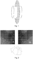
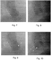
Fig. 7 is a first angiographic image which shows the aortic root from behind; -
Fig. 8 is a second angiographic image which shows the aortic root from below; -
Fig. 9 is the image ofFig. 7 segmented and with a coronary leaflet indicated as point of interest; -
Fig. 10 is the image ofFig. 8 segmented and with the corresponding coronary leaflet indicated as point of interest; -
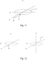
Fig. 11 is a simplified sketch showing the optimal direction vector for a point of interest; -
Fig. 12 shows two optimal views having the same optimal direction; -
Fig. 13 is the angiographic image of the same aortic root as in the previous figures obtained from a perspective as determined with the method according to the invention; -
FIG 14 is a schematic drawing of the optimal projection image to be used for replacing the aortic leaflet or placing a stent. -
Fig. 1 shows a tubular organ, like an artery, having an elliptical cross section. All possible optimal projection view directions for this asymmetrical object lie on the indicated grey circle which is perpendicular to the axis of the object. However an optimal projection view direction chosen at point B will contain different object information than an optimal projection view direction chosen from point A.Fig. 2 helps explaining that. This figure shows the difference in coronary artery visibility in the coronary root when looking from different orthogonal views. In this figure the aortic root (shown in lowerfigure 2 in plant view) is seen from two perspectives. When looking through perspective A the coronary arteries that arise from the aortic root can be seen clearly (see the upper leftfigure 2 ), however when looking via perspective B at the same aortic root both coronary arteries are absent in the image information (see the upper rightfigure 2 ). The absence of the coronary arteries in the image information can lead to serious complications during an intervention. If, for instance, a stent is placed in front of the coronary arteries the blood flow to the coronary arteries is blocked leading to irreversible damage for the patient. - With reference to the block diagram of
Fig. 3 , an embodiment of the invention is now described. - In this example it is assumed to have at disposal at least two projection images of an object of interest. Any image device capable of providing 2D images can be used for the purpose. For example a bi-plane or single plane angiographic system can be used such as those manufactured, for example, by Siemens (Artis zee Biplane) or Philips (Allura Xper FD).
- In the step indicated with
reference number 10 the object of interest is segmented in each projection image or in at least two of them coming from different perspectives. This can be done according to any known method such as the one disclosed in Y. Jiang et.al. "X-ray image segmentation using active contour model with global constraints" IEEE Symposium on Computational Intelligence in Image and Signal Processing, 2007, CIISP 2007 pages 240-245. The results are projection images with the border 101 of the object of interest overlaid, as for example shown inFig. 9 and Fig. 10 . - In the following step 20 a point of interest is identified by the user in at least two projections. For example in case the object is a coronary root such point can be the right coronary leaflet 201 as indicated in
Fig. 9 and Fig. 10 . - According to an advantageous embodiment, once the position of the point of interest in the first projection is identified by the user, the system can automatically indicate a region in the second projection to provide a guidance to assist the user in selecting the correct point of interest within such second projection. This is achieved by taking into accounts the properties of the epipolar geometry as taught, for example, by Joon Hee Han et al. "Contour matching using epipolar geometry" Pattern Analysis and Machine Intelligence, Volume 22, Issue 4, April 2000, Pages 358-370.
- The next step is the generation of a 3D model (also called three-dimensional reconstruction or three-dimensional surface reconstruction within the present disclosure) starting from the at least two projections identified as
step 30. This is known and can be done, for example, according to the paper "A novel dedicated 3-dimensional quantitative coronary analysis methodology for bifurcation lesions", Yoshinobu Onuma, Chrysafios Girasis, Jean-Paul Aben, Giovanna Sarno, Nicolo Piazza, Coen Lokkerbol, Marie-Angel Morel, Patrick W. Serruys, EuroIntervention 2011; 6:1-00. - The result of this step is a three-dimensional surface reconstruction of the object of interest as shown in
Fig. 4 for the case of a tubular organ. - Because the user is usually interested in a smaller section of the generated 3D model, the user can indicate a
sub segment 502', 502" within the 3D model that will be used for further calculations (seeFig. 5 ). This can be done, for instance, by indicating two lines 401, 402 in one of the 2D images, one representing the beginning and the other representing the end of the wanted segment. This is preferably done in the 2D images because the segment of interest is best seen there. However, this can also be done directly on the 3D model. - Using the feature indicated by the points of interest in
step 20 an optimal projection is then determined according to the following steps. - First, all view directions that are perpendicular to the section of
interest 502', 502", or to the whole 3D object, are determined. This is done, for example, according to the method described in the paper "Determination of optimal angiographic viewing angles: basic principles and evaluation study", Adrie C. M. Dumay, Johan H. C. Reiber, Jan J. Gerbrands, IEEE Trans. Med. Imaging, vol. 13, N. 1, March 1994. - Using the 3D model (step 30) generated earlier the orientation of the indicated section or the whole 3D object (step 40) can be derived. An optimal view direction is defined as a view direction that is perpendicular to the orientation of the 3D model or a section thereof. Because the model can be looked at from different angles that are all perpendicular to it, this step gives us a various amount of optimal view directions that all lie on planes perpendicular to the object (see
figure 1 ). - Then the points of interest 201 that were indicated in the 2D angiographic images in
step 20 are matched. That is a 3D equivalent point for the feature is calculated. This is done using techniques similar to the ones used for the 3D reconstruction as described instep 30. - The 3D equivalent point is then translated to the 3D model that was generated in
step 30, being the closest point on the 3D surface of the 3D model. That is the best representation of the 3D point on the 3D surface is found. - In the situation where the user has indicated a point of interest in only one projection, the 3D model is back projected to the projection in which the point was indicated. The point of interest is then matched to the model to find its 3D equivalent. This is preferably achieved when the point of interest is situated in the section of the 3D model facing the user, i.e. the point of interest as indicated by the user does not lie on the backside of the 3D model.
- The next step is to select the optimal view direction (from all possible optimal view directions) that also contains the 3D
equivalent point 501. This is done by determining adirection vector 503 starting from the centre of theoptimal projection outline 502 of the model at the height of the 3Dequivalent point 501 and heading outward through such point as shown inFig. 11 . - Because the
direction vector 503 is constructed using the plane of possible optimal projection view directions, it is ensured that thedirection vector 503 is perpendicular to the indicated section. Also because the direction runs through the 3Dequivalent point 501, it is ensured that an optimal projection view derived from this direction vector contains information about the indicated point of interest 201. - From the
direction vector 503 twoviewing vectors 503', 503" can be determined, one looking along the direction vector and one looking against the direction vector. Eachviewing vector 503', 503" represents an image perspective indicated by the angulations of an x-ray system (both the systems rotation and angulation). - One of the two image perspectives will probably lie outside of the range of the used imaging modality, therefore this image perspective cannot be recorded. This can be due, for instance, to the fact that a C-arm can only rotate and/or angulate a certain amount of degrees and is therefore not able to achieve one of the given perspectives.
- This will result in the other image perspective being the suitable one. This is dependent on the imaging modality being used.
- Using this outcome the clinician can then acquire the image that belongs to this optimal projection and continue the procedure with the maximum amount of object information and the least amount of time and burden to the patient spent on finding that information.
Fig. 13 shows the optimal projection image obtained processing the two images ofFig. 7 and 8 with a method according to the invention.Fig. 14 is a sketch of the image so obtained which represents a view of the aortic root with the right leaflet R shown between the non-coronary (posterior) P and the left leaflet L of the aortic valve, a perspective considered particularly useful for TAVI procedures.
Claims (17)
- Method for determining optimal projection images of an object, particularly an asymmetrical object, the method comprising the following steps:a) generating a three-dimensional surface reconstruction of the object from two or more bi-dimensional images of the object which have been obtained from different perspectives;b) receiving from a user indications for locating a segment of interest on the 3D reconstruction;c) determining a plane containing optimal view directions in terms of foreshortening for this segment of interest, wherein
step b) comprises receiving from the user the position of a point or area of interest (201) in at least one of the bi-dimensional images used for the three-dimensional reconstruction of the object as in step a), the method further comprising the steps ofd) determining, on the three-dimensional surface, a 3D equivalent point (501) of the point or area of interest (201); characterised in that the method further comprises the step ofe) selecting among the optimal view directions as determined in step c) those going through the 3D equivalent point (501) as defined in step d). - Method according to claim 1, wherein the plane as determined in step c) is perpendicular to the main orientation of the section of interest.
- Method according to claim 1 or 2, wherein the plane as determined in step c) intersects the three-dimensional surface to obtain a geometric figure having a centre of symmetry.
- Method according to claim 3, wherein step e) comprises determining the direction (503) of the line passing through the centre of symmetry and the 3D equivalent point (501).
- Method according to any preceding claim, wherein step d) comprises determining a 3D equivalent point (501) from the point or area of interest (201) on at least one of the bi-dimensional images used for the three-dimensional reconstruction of the object, the 3D equivalent point (501) being determined by back-projecting the 3D model onto such bi-dimensional image where the selected point or area of interest lies, finding a point on the bi-dimensional back-projected image the closest to such point or area of interest, determining the point on the 3D model corresponding to such point on the bi-dimensional back-projected image.
- Method according to any preceding claim, wherein step d) comprises determining a 3D equivalent point (501) from the point or area of interest on at least two of the bi-dimensional images used for the three-dimensional reconstruction of the object, the 3D equivalent point being a point on the 3D surface the closest to such 3D point.
- Method according to claim 6, characterized in comprising the following steps:- receiving from the user the position of a point or area of interest in a first bi-dimensional image;- automatically indicating a region in a second bi-dimensional image to provide a guidance to assist the user in selecting the corresponding point of interest within such second bi-dimensional image;- receiving from the user the position of such point or area of interest within such region of the second bi-dimensional image.
- Method according to any preceding claim, wherein the object or a part thereof is segmented in at least two of the bi-dimensional images used for the three-dimensional reconstruction.
- Method according to any preceding claim, wherein the section of interest (502', 502") is manually or automatically identified on the bi-dimensional images (401, 402) used for the three-dimensional reconstruction of the object.
- Method according to any preceding claim, wherein a suitable optimal view is determined among those two (503', 503") having the same direction as a function of the modality used for acquiring the bi-dimensional images.
- Method according to any preceding claim, wherein the at least two bi-dimensional images are angiographic images showing part or the whole aortic root, the point or area of interest being a coronary leaflet, particularly the right coronary leaflet.
- Method according to claim 11, wherein the optimal projection image is a bi-dimensional image showing the right coronary leaflet in a central position with the posterior and left leaflets respectively located at opposite sides of such right coronary leaflet.
- A computer product directly loadable into the memory of a digital computer and comprising software code portions for performing the method according to any of the preceding claims when the product is run on a computer.
- Apparatus for acquiring bi-dimensional projection images of a tri-dimensional object, the apparatus comprising means for receiving from a user indications on the position of a point or area of interest in at least two bi-dimensional images of the object obtained from different perspectives and processing means programmed for performing the method according to any preceding claim to determine a perspective for obtaining an optimal projection image of the object.
- Apparatus according to claim 14, characterized in that it is an angiographic apparatus of the C-arm or L-arm type with X-ray source and image intensifier respectively located at opposite sides of the arm, such arm being movable at least according to a rotation angle and an angulation angle with reference to a patient to obtain bi-dimensional images from different perspectives, the processing means being programmed to calculate rotation and angulation angles of the arm for obtaining optimal projection images.
- Apparatus according to claim 15, further comprising actuating means to automatically or semi-automatically rotate the arm, and/or display means for providing to a user indications for manually rotating the arm, according to rotation and angulation angles calculated for obtaining an optimal projection image.
- Apparatus according to claim 15 or 16, wherein among two perspectives having the same direction, the processing means is programmed to select the one corresponding to a rotation and angulation angle within the range of possible rotation and angulation angles of the apparatus.
Priority Applications (3)
| Application Number | Priority Date | Filing Date | Title |
|---|---|---|---|
| EP11166739.0A EP2525328B1 (en) | 2011-05-19 | 2011-05-19 | Method and apparatus for determining optimal projection images |
| US13/455,696 US9129418B2 (en) | 2011-05-19 | 2012-04-25 | Method and apparatus for determining optimal image viewing direction |
| JP2012114270A JP6030340B2 (en) | 2011-05-19 | 2012-05-18 | Method and apparatus for determining optimal projection images by computer implementation |
Applications Claiming Priority (1)
| Application Number | Priority Date | Filing Date | Title |
|---|---|---|---|
| EP11166739.0A EP2525328B1 (en) | 2011-05-19 | 2011-05-19 | Method and apparatus for determining optimal projection images |
Publications (2)
| Publication Number | Publication Date |
|---|---|
| EP2525328A1 EP2525328A1 (en) | 2012-11-21 |
| EP2525328B1 true EP2525328B1 (en) | 2017-10-18 |
Family
ID=44660473
Family Applications (1)
| Application Number | Title | Priority Date | Filing Date |
|---|---|---|---|
| EP11166739.0A Active EP2525328B1 (en) | 2011-05-19 | 2011-05-19 | Method and apparatus for determining optimal projection images |
Country Status (3)
| Country | Link |
|---|---|
| US (1) | US9129418B2 (en) |
| EP (1) | EP2525328B1 (en) |
| JP (1) | JP6030340B2 (en) |
Families Citing this family (13)
| Publication number | Priority date | Publication date | Assignee | Title |
|---|---|---|---|---|
| US10210956B2 (en) | 2012-10-24 | 2019-02-19 | Cathworks Ltd. | Diagnostically useful results in real time |
| WO2014064702A2 (en) | 2012-10-24 | 2014-05-01 | Cathworks Ltd. | Automated measurement system and method for coronary artery disease scoring |
| EP3954298A3 (en) | 2013-10-24 | 2022-03-16 | Cathworks Ltd. | Vascular characteristic determination with correspondence modeling of a vascular tree |
| EP3145434A4 (en) * | 2014-05-21 | 2018-03-07 | The Royal Institution for the Advancement of Learning / McGill University | Methods and systems for anatomical structure and transcatheter device visualization |
| JP6499328B2 (en) | 2015-06-17 | 2019-04-10 | コーニンクレッカ フィリップス エヌ ヴェKoninklijke Philips N.V. | Determination of C-arm angulation for valve positioning |
| EP3128481B1 (en) * | 2015-08-04 | 2019-12-18 | Pie Medical Imaging BV | Method and apparatus to improve a 3d + time reconstruction |
| EP3206183A1 (en) | 2016-02-11 | 2017-08-16 | Pie Medical Imaging BV | Method and apparatus for user guidance for the choice of a two-dimensional angiographic projection |
| US10733792B2 (en) | 2016-02-11 | 2020-08-04 | Pie Medical Imaging B.V. | Method and apparatus for user guidance for the choice of a two-dimensional angiographic projection |
| EP4241694A3 (en) | 2016-05-16 | 2023-12-20 | Cathworks Ltd. | Selection of vascular paths from images |
| IL263065B1 (en) | 2016-05-16 | 2024-04-01 | Cathworks Ltd | System for vascular assessment |
| US20180330018A1 (en) * | 2017-05-12 | 2018-11-15 | The Boeing Company | Methods and systems for part geometry extraction |
| US10861157B2 (en) | 2019-04-04 | 2020-12-08 | Medtronic Vascular, Inc. | System and methods for determining modified fractional flow reserve values |
| US20230135088A1 (en) * | 2021-10-28 | 2023-05-04 | Nvidia Corporation | 3d surface reconstruction with point cloud densification using deep neural networks for autonomous systems and applications |
Family Cites Families (10)
| Publication number | Priority date | Publication date | Assignee | Title |
|---|---|---|---|---|
| US20030074011A1 (en) * | 1998-09-24 | 2003-04-17 | Super Dimension Ltd. | System and method of recording and displaying in context of an image a location of at least one point-of-interest in a body during an intra-body medical procedure |
| DE19936364A1 (en) * | 1999-08-03 | 2001-02-15 | Siemens Ag | Identification and localisation of marks in a 3D medical scanning process |
| WO2001085030A1 (en) * | 2000-05-09 | 2001-11-15 | Paieon Inc. | System and method for three-dimensional reconstruction of an artery |
| JP2002119502A (en) * | 2000-10-17 | 2002-04-23 | Toshiba Corp | Medical device |
| AU2003234576A1 (en) * | 2002-05-17 | 2003-12-02 | Case Western Reserve University | Chemical shift markers for improved wireless fiducial marker tracking |
| JP2005528157A (en) * | 2002-06-04 | 2005-09-22 | コーニンクレッカ フィリップス エレクトロニクス エヌ ヴィ | Hybrid 3D reconstruction of coronary artery structure based on rotational angiography |
| US20050015048A1 (en) * | 2003-03-12 | 2005-01-20 | Chiu Jessica G. | Infusion treatment agents, catheters, filter devices, and occlusion devices, and use thereof |
| US8155411B2 (en) * | 2008-07-22 | 2012-04-10 | Pie Medical Imaging B.V. | Method, apparatus and computer program for quantitative bifurcation analysis in 3D using multiple 2D angiographic images |
| EP2485646B1 (en) * | 2009-10-06 | 2013-11-06 | Koninklijke Philips N.V. | Automatic c-arm viewing angles for structural heart disease treatment |
| JP6169832B2 (en) * | 2011-11-29 | 2017-07-26 | 東芝メディカルシステムズ株式会社 | X-ray equipment |
-
2011
- 2011-05-19 EP EP11166739.0A patent/EP2525328B1/en active Active
-
2012
- 2012-04-25 US US13/455,696 patent/US9129418B2/en active Active
- 2012-05-18 JP JP2012114270A patent/JP6030340B2/en active Active
Non-Patent Citations (1)
| Title |
|---|
| None * |
Also Published As
| Publication number | Publication date |
|---|---|
| EP2525328A1 (en) | 2012-11-21 |
| US20120293498A1 (en) | 2012-11-22 |
| JP6030340B2 (en) | 2016-11-24 |
| US9129418B2 (en) | 2015-09-08 |
| JP2012245355A (en) | 2012-12-13 |
Similar Documents
| Publication | Publication Date | Title |
|---|---|---|
| EP2525328B1 (en) | Method and apparatus for determining optimal projection images | |
| EP2570079B1 (en) | Method and apparatus for determining optimal 3D reconstruction of an object | |
| JP6333979B2 (en) | Intervention X-ray system with automatic isocentering | |
| US9811939B2 (en) | Method and system for registering intravascular images | |
| CN101150986B (en) | Method and apparatus for the observation of a catheter in a vessel system | |
| US8463014B2 (en) | Optimal rotational trajectory determination for RA based on pre-determined optimal view map | |
| JP4559501B2 (en) | Cardiac function display device, cardiac function display method and program thereof | |
| EP1513449B1 (en) | Rotational angiography based hybrid 3-d reconstruction of coronary arterial structure | |
| EP2086415B1 (en) | Combining x-ray with intravascularly acquired data | |
| JP5491700B2 (en) | Data processing apparatus and X-ray apparatus | |
| EP3128481B1 (en) | Method and apparatus to improve a 3d + time reconstruction | |
| US20060036167A1 (en) | Vascular image processing | |
| JP2004243117A (en) | Method for obtaining physical parameters of physiological structure | |
| EP2049021B1 (en) | Automatic iso-centering for rotational angiography | |
| JP6936882B2 (en) | Medical viewing system with viewing surface determination | |
| JP2018535019A (en) | System for tracking an ultrasound probe in a body part | |
| JP2009022754A (en) | Method for correcting registration of radiography images | |
| JP2008035895A (en) | Image processing method and image processing program | |
| US9036880B2 (en) | High-resolution three-dimensional medical imaging with dynamic real-time information | |
| US20220000442A1 (en) | Image orientation setting apparatus, image orientation setting method, and image orientation setting program | |
| EP3454752B1 (en) | Anatomy adapted acquisition with fixed multi-source x-ray system |
Legal Events
| Date | Code | Title | Description |
|---|---|---|---|
| PUAI | Public reference made under article 153(3) epc to a published international application that has entered the european phase |
Free format text: ORIGINAL CODE: 0009012 |
|
| 17P | Request for examination filed |
Effective date: 20120316 |
|
| AK | Designated contracting states |
Kind code of ref document: A1 Designated state(s): AL AT BE BG CH CY CZ DE DK EE ES FI FR GB GR HR HU IE IS IT LI LT LU LV MC MK MT NL NO PL PT RO RS SE SI SK SM TR |
|
| AX | Request for extension of the european patent |
Extension state: BA ME |
|
| RAP1 | Party data changed (applicant data changed or rights of an application transferred) |
Owner name: PIE MEDICAL IMAGING BV |
|
| 17Q | First examination report despatched |
Effective date: 20130404 |
|
| GRAP | Despatch of communication of intention to grant a patent |
Free format text: ORIGINAL CODE: EPIDOSNIGR1 |
|
| INTG | Intention to grant announced |
Effective date: 20170623 |
|
| GRAS | Grant fee paid |
Free format text: ORIGINAL CODE: EPIDOSNIGR3 |
|
| GRAA | (expected) grant |
Free format text: ORIGINAL CODE: 0009210 |
|
| AK | Designated contracting states |
Kind code of ref document: B1 Designated state(s): AL AT BE BG CH CY CZ DE DK EE ES FI FR GB GR HR HU IE IS IT LI LT LU LV MC MK MT NL NO PL PT RO RS SE SI SK SM TR |
|
| REG | Reference to a national code |
Ref country code: GB Ref legal event code: FG4D |
|
| REG | Reference to a national code |
Ref country code: CH Ref legal event code: EP |
|
| REG | Reference to a national code |
Ref country code: AT Ref legal event code: REF Ref document number: 938554 Country of ref document: AT Kind code of ref document: T Effective date: 20171115 Ref country code: IE Ref legal event code: FG4D |
|
| REG | Reference to a national code |
Ref country code: DE Ref legal event code: R096 Ref document number: 602011042451 Country of ref document: DE |
|
| REG | Reference to a national code |
Ref country code: NL Ref legal event code: FP |
|
| REG | Reference to a national code |
Ref country code: LT Ref legal event code: MG4D |
|
| REG | Reference to a national code |
Ref country code: AT Ref legal event code: MK05 Ref document number: 938554 Country of ref document: AT Kind code of ref document: T Effective date: 20171018 |
|
| PG25 | Lapsed in a contracting state [announced via postgrant information from national office to epo] |
Ref country code: SE Free format text: LAPSE BECAUSE OF FAILURE TO SUBMIT A TRANSLATION OF THE DESCRIPTION OR TO PAY THE FEE WITHIN THE PRESCRIBED TIME-LIMIT Effective date: 20171018 Ref country code: LT Free format text: LAPSE BECAUSE OF FAILURE TO SUBMIT A TRANSLATION OF THE DESCRIPTION OR TO PAY THE FEE WITHIN THE PRESCRIBED TIME-LIMIT Effective date: 20171018 Ref country code: FI Free format text: LAPSE BECAUSE OF FAILURE TO SUBMIT A TRANSLATION OF THE DESCRIPTION OR TO PAY THE FEE WITHIN THE PRESCRIBED TIME-LIMIT Effective date: 20171018 Ref country code: ES Free format text: LAPSE BECAUSE OF FAILURE TO SUBMIT A TRANSLATION OF THE DESCRIPTION OR TO PAY THE FEE WITHIN THE PRESCRIBED TIME-LIMIT Effective date: 20171018 Ref country code: NO Free format text: LAPSE BECAUSE OF FAILURE TO SUBMIT A TRANSLATION OF THE DESCRIPTION OR TO PAY THE FEE WITHIN THE PRESCRIBED TIME-LIMIT Effective date: 20180118 |
|
| REG | Reference to a national code |
Ref country code: FR Ref legal event code: PLFP Year of fee payment: 8 |
|
| PG25 | Lapsed in a contracting state [announced via postgrant information from national office to epo] |
Ref country code: AT Free format text: LAPSE BECAUSE OF FAILURE TO SUBMIT A TRANSLATION OF THE DESCRIPTION OR TO PAY THE FEE WITHIN THE PRESCRIBED TIME-LIMIT Effective date: 20171018 Ref country code: GR Free format text: LAPSE BECAUSE OF FAILURE TO SUBMIT A TRANSLATION OF THE DESCRIPTION OR TO PAY THE FEE WITHIN THE PRESCRIBED TIME-LIMIT Effective date: 20180119 Ref country code: IS Free format text: LAPSE BECAUSE OF FAILURE TO SUBMIT A TRANSLATION OF THE DESCRIPTION OR TO PAY THE FEE WITHIN THE PRESCRIBED TIME-LIMIT Effective date: 20180218 Ref country code: LV Free format text: LAPSE BECAUSE OF FAILURE TO SUBMIT A TRANSLATION OF THE DESCRIPTION OR TO PAY THE FEE WITHIN THE PRESCRIBED TIME-LIMIT Effective date: 20171018 Ref country code: BG Free format text: LAPSE BECAUSE OF FAILURE TO SUBMIT A TRANSLATION OF THE DESCRIPTION OR TO PAY THE FEE WITHIN THE PRESCRIBED TIME-LIMIT Effective date: 20180118 Ref country code: RS Free format text: LAPSE BECAUSE OF FAILURE TO SUBMIT A TRANSLATION OF THE DESCRIPTION OR TO PAY THE FEE WITHIN THE PRESCRIBED TIME-LIMIT Effective date: 20171018 Ref country code: HR Free format text: LAPSE BECAUSE OF FAILURE TO SUBMIT A TRANSLATION OF THE DESCRIPTION OR TO PAY THE FEE WITHIN THE PRESCRIBED TIME-LIMIT Effective date: 20171018 |
|
| REG | Reference to a national code |
Ref country code: DE Ref legal event code: R097 Ref document number: 602011042451 Country of ref document: DE |
|
| PG25 | Lapsed in a contracting state [announced via postgrant information from national office to epo] |
Ref country code: CZ Free format text: LAPSE BECAUSE OF FAILURE TO SUBMIT A TRANSLATION OF THE DESCRIPTION OR TO PAY THE FEE WITHIN THE PRESCRIBED TIME-LIMIT Effective date: 20171018 Ref country code: DK Free format text: LAPSE BECAUSE OF FAILURE TO SUBMIT A TRANSLATION OF THE DESCRIPTION OR TO PAY THE FEE WITHIN THE PRESCRIBED TIME-LIMIT Effective date: 20171018 Ref country code: EE Free format text: LAPSE BECAUSE OF FAILURE TO SUBMIT A TRANSLATION OF THE DESCRIPTION OR TO PAY THE FEE WITHIN THE PRESCRIBED TIME-LIMIT Effective date: 20171018 Ref country code: SK Free format text: LAPSE BECAUSE OF FAILURE TO SUBMIT A TRANSLATION OF THE DESCRIPTION OR TO PAY THE FEE WITHIN THE PRESCRIBED TIME-LIMIT Effective date: 20171018 |
|
| PLBE | No opposition filed within time limit |
Free format text: ORIGINAL CODE: 0009261 |
|
| STAA | Information on the status of an ep patent application or granted ep patent |
Free format text: STATUS: NO OPPOSITION FILED WITHIN TIME LIMIT |
|
| PG25 | Lapsed in a contracting state [announced via postgrant information from national office to epo] |
Ref country code: RO Free format text: LAPSE BECAUSE OF FAILURE TO SUBMIT A TRANSLATION OF THE DESCRIPTION OR TO PAY THE FEE WITHIN THE PRESCRIBED TIME-LIMIT Effective date: 20171018 Ref country code: IT Free format text: LAPSE BECAUSE OF FAILURE TO SUBMIT A TRANSLATION OF THE DESCRIPTION OR TO PAY THE FEE WITHIN THE PRESCRIBED TIME-LIMIT Effective date: 20171018 Ref country code: SM Free format text: LAPSE BECAUSE OF FAILURE TO SUBMIT A TRANSLATION OF THE DESCRIPTION OR TO PAY THE FEE WITHIN THE PRESCRIBED TIME-LIMIT Effective date: 20171018 Ref country code: PL Free format text: LAPSE BECAUSE OF FAILURE TO SUBMIT A TRANSLATION OF THE DESCRIPTION OR TO PAY THE FEE WITHIN THE PRESCRIBED TIME-LIMIT Effective date: 20171018 |
|
| 26N | No opposition filed |
Effective date: 20180719 |
|
| PG25 | Lapsed in a contracting state [announced via postgrant information from national office to epo] |
Ref country code: SI Free format text: LAPSE BECAUSE OF FAILURE TO SUBMIT A TRANSLATION OF THE DESCRIPTION OR TO PAY THE FEE WITHIN THE PRESCRIBED TIME-LIMIT Effective date: 20171018 |
|
| REG | Reference to a national code |
Ref country code: CH Ref legal event code: PL |
|
| REG | Reference to a national code |
Ref country code: BE Ref legal event code: MM Effective date: 20180531 |
|
| PG25 | Lapsed in a contracting state [announced via postgrant information from national office to epo] |
Ref country code: MC Free format text: LAPSE BECAUSE OF FAILURE TO SUBMIT A TRANSLATION OF THE DESCRIPTION OR TO PAY THE FEE WITHIN THE PRESCRIBED TIME-LIMIT Effective date: 20171018 |
|
| REG | Reference to a national code |
Ref country code: IE Ref legal event code: MM4A |
|
| PG25 | Lapsed in a contracting state [announced via postgrant information from national office to epo] |
Ref country code: CH Free format text: LAPSE BECAUSE OF NON-PAYMENT OF DUE FEES Effective date: 20180531 Ref country code: LI Free format text: LAPSE BECAUSE OF NON-PAYMENT OF DUE FEES Effective date: 20180531 |
|
| PG25 | Lapsed in a contracting state [announced via postgrant information from national office to epo] |
Ref country code: LU Free format text: LAPSE BECAUSE OF NON-PAYMENT OF DUE FEES Effective date: 20180519 |
|
| PG25 | Lapsed in a contracting state [announced via postgrant information from national office to epo] |
Ref country code: IE Free format text: LAPSE BECAUSE OF NON-PAYMENT OF DUE FEES Effective date: 20180519 |
|
| PG25 | Lapsed in a contracting state [announced via postgrant information from national office to epo] |
Ref country code: BE Free format text: LAPSE BECAUSE OF NON-PAYMENT OF DUE FEES Effective date: 20180531 |
|
| PG25 | Lapsed in a contracting state [announced via postgrant information from national office to epo] |
Ref country code: MT Free format text: LAPSE BECAUSE OF NON-PAYMENT OF DUE FEES Effective date: 20180519 |
|
| PG25 | Lapsed in a contracting state [announced via postgrant information from national office to epo] |
Ref country code: TR Free format text: LAPSE BECAUSE OF FAILURE TO SUBMIT A TRANSLATION OF THE DESCRIPTION OR TO PAY THE FEE WITHIN THE PRESCRIBED TIME-LIMIT Effective date: 20171018 |
|
| PG25 | Lapsed in a contracting state [announced via postgrant information from national office to epo] |
Ref country code: PT Free format text: LAPSE BECAUSE OF FAILURE TO SUBMIT A TRANSLATION OF THE DESCRIPTION OR TO PAY THE FEE WITHIN THE PRESCRIBED TIME-LIMIT Effective date: 20171018 Ref country code: HU Free format text: LAPSE BECAUSE OF FAILURE TO SUBMIT A TRANSLATION OF THE DESCRIPTION OR TO PAY THE FEE WITHIN THE PRESCRIBED TIME-LIMIT; INVALID AB INITIO Effective date: 20110519 |
|
| PG25 | Lapsed in a contracting state [announced via postgrant information from national office to epo] |
Ref country code: MK Free format text: LAPSE BECAUSE OF NON-PAYMENT OF DUE FEES Effective date: 20171018 Ref country code: CY Free format text: LAPSE BECAUSE OF FAILURE TO SUBMIT A TRANSLATION OF THE DESCRIPTION OR TO PAY THE FEE WITHIN THE PRESCRIBED TIME-LIMIT Effective date: 20171018 |
|
| PG25 | Lapsed in a contracting state [announced via postgrant information from national office to epo] |
Ref country code: AL Free format text: LAPSE BECAUSE OF FAILURE TO SUBMIT A TRANSLATION OF THE DESCRIPTION OR TO PAY THE FEE WITHIN THE PRESCRIBED TIME-LIMIT Effective date: 20171018 |
|
| P01 | Opt-out of the competence of the unified patent court (upc) registered |
Effective date: 20230309 |
|
| PGFP | Annual fee paid to national office [announced via postgrant information from national office to epo] |
Ref country code: NL Payment date: 20230418 Year of fee payment: 13 |
|
| PGFP | Annual fee paid to national office [announced via postgrant information from national office to epo] |
Ref country code: FR Payment date: 20230407 Year of fee payment: 13 Ref country code: DE Payment date: 20230418 Year of fee payment: 13 |
|
| PGFP | Annual fee paid to national office [announced via postgrant information from national office to epo] |
Ref country code: GB Payment date: 20230407 Year of fee payment: 13 |