EP2520892A1 - Measuring apparatus - Google Patents
Measuring apparatus Download PDFInfo
- Publication number
- EP2520892A1 EP2520892A1 EP12163268A EP12163268A EP2520892A1 EP 2520892 A1 EP2520892 A1 EP 2520892A1 EP 12163268 A EP12163268 A EP 12163268A EP 12163268 A EP12163268 A EP 12163268A EP 2520892 A1 EP2520892 A1 EP 2520892A1
- Authority
- EP
- European Patent Office
- Prior art keywords
- section
- housing
- wall
- longitudinal axis
- electronic components
- Prior art date
- Legal status (The legal status is an assumption and is not a legal conclusion. Google has not performed a legal analysis and makes no representation as to the accuracy of the status listed.)
- Granted
Links
Images


Classifications
-
- G—PHYSICS
- G01—MEASURING; TESTING
- G01F—MEASURING VOLUME, VOLUME FLOW, MASS FLOW OR LIQUID LEVEL; METERING BY VOLUME
- G01F23/00—Indicating or measuring liquid level or level of fluent solid material, e.g. indicating in terms of volume or indicating by means of an alarm
- G01F23/22—Indicating or measuring liquid level or level of fluent solid material, e.g. indicating in terms of volume or indicating by means of an alarm by measuring physical variables, other than linear dimensions, pressure or weight, dependent on the level to be measured, e.g. by difference of heat transfer of steam or water
- G01F23/28—Indicating or measuring liquid level or level of fluent solid material, e.g. indicating in terms of volume or indicating by means of an alarm by measuring physical variables, other than linear dimensions, pressure or weight, dependent on the level to be measured, e.g. by difference of heat transfer of steam or water by measuring the variations of parameters of electromagnetic or acoustic waves applied directly to the liquid or fluent solid material
- G01F23/296—Acoustic waves
-
- G—PHYSICS
- G01—MEASURING; TESTING
- G01D—MEASURING NOT SPECIALLY ADAPTED FOR A SPECIFIC VARIABLE; ARRANGEMENTS FOR MEASURING TWO OR MORE VARIABLES NOT COVERED IN A SINGLE OTHER SUBCLASS; TARIFF METERING APPARATUS; MEASURING OR TESTING NOT OTHERWISE PROVIDED FOR
- G01D11/00—Component parts of measuring arrangements not specially adapted for a specific variable
- G01D11/24—Housings ; Casings for instruments
- G01D11/245—Housings for sensors
Definitions
- the invention relates to a measuring device with a housing in which electronic components are arranged.
- Gauges are used in almost all industries to acquire physical quantities, e.g. of levels or pressures.
- Measuring devices usually have a device for detecting the physical quantity, which converts the physical quantity into an electrical quantity and makes it available for evaluation, processing and / or display. For this purpose, depending on the meter more or less complex electronic circuits are provided in the meter, which have electronic components.
- An example of a meter is level limit switches that detect the reaching of a predetermined level and, e.g. be used as overfill protection or as pump idle protection.
- level limit switches are on the market, which have a cup-shaped housing whose bottom forms a membrane.
- the membrane is set in operation by at least one arranged inside the housing piezoelectric element in vibration.
- On the membrane for example, in the container projecting oscillating rods are formed, which perform vibrations parallel to the longitudinal axis during operation.
- the constructed of membrane and vibrating rods vibration structure is preferably excited to resonant vibrations.
- the resonant frequency of the vibration structure depends on whether the oscillating rods are covered by the contents or not. On the basis of the resonant frequency can be determined whether the oscillating rods are covered by the contents or not. Are the oscillating rods covered by the contents, so a predetermined level is reached.
- the predetermined level is predetermined by an installation height of the level limit switch in the container.
- Measuring instruments are placed at a measuring location, e.g. on a container, mounted. In some cases, relatively high temperatures may occur at the measuring location. Temperatures in closed containers reach many industries, e.g. Temperatures of up to 150 ° C. In addition, relatively high temperatures, e.g. 50 ° C, occur. Electronic components are very sensitive to temperature. As a rule, commercially available electronic components can only be used at temperatures of up to 85 ° C.
- the housing must be made very robust. In many applications, it is required that the housing withstand a load of at most 1000 N across a longitudinal axis of the housing without causing the housing to break.
- Metallic housings are very robust and are also easy to clean. Accordingly, metallic housings for measuring devices are preferably used in industrial metrology.
- a wall of the second section has at least one area with reduced wall thickness.
- At least one circumferential groove is provided in the wall of the second section.
- a plurality of regions with reduced wall thickness are arranged side by side in the wall of the second section, which are separated from one another by webs.
- a plurality of layers of juxtaposed regions with reduced wall thickness are arranged one above the other in the wall of the second section, wherein adjacent regions of a layer are separated from one another by webs and webs of adjacent layers are offset from one another.
- a support body made of an insulator is arranged in the interior of the housing in the region of the second portion for increasing a mechanical strength of the housing relative to loads perpendicular to the longitudinal axis of the housing.
- the wall of the second section has honeycomb-shaped bulges.
- a plurality of circumferential grooves are provided in the wall of the second portion, wherein the grooves are arranged alternately on an inner side of the wall and an outer side of the wall.
- Fig. 1 shows a section through a measuring device according to the invention.
- it is a level limit switch for the detection and / or monitoring of a predetermined level in a container, as used in the measurement and control technology.
- the measuring device comprises a housing 1 made of a metal, e.g. a stainless steel, comprising a first, a second and a third section 3, 5, 7.
- a housing 1 made of a metal, e.g. a stainless steel, comprising a first, a second and a third section 3, 5, 7.
- the first section 3 has the shape of a cylinder 9 terminated by a membrane 9 at its end.
- a device 11 is provided for fastening the housing 1 at a measuring location.
- the device 11 is an external thread, which is integrally formed on the first portion 3.
- the housing 1 is screwed by means of the external thread into a mating thread at the measuring location.
- the housing 1 is screwed into an opening 13 of a container.
- Other fixtures e.g. Mounting flanges are also usable.
- a piezoelectric element 17 is attached thereto, e.g. glued, through which the membrane 9 is displaceable in bending oscillations.
- the second section 5 of the housing 1 adjoins.
- the second section 5 is also substantially cylindrical.
- the second portion 5 is formed so that when there is a temperature difference between an environment of the first portion 3 and an environment of the third portion 7, a small heat flow parallel to a longitudinal axis L of the housing 1 flows through the second portion 5. As a result, a heat transfer from the first to the third section 3, 7 is reduced.
- the third section 7 is likewise cylindrical and adjoins a side of the second section 5 facing away from the first section 3.
- electronic components 19 are arranged on a printed circuit board 21, which by means of a in Fig. 1 only shown schematically holder 23 is mounted in the third section 7.
- the second section 5 causes a protection of the third section 7, or the components 19 located therein before heating.
- the second section 5 is formed so that at a temperature difference between the environment of the first portion 3 and the vicinity of the third portion 7 only a small heat flow parallel to a longitudinal axis L of the housing 1 flows through the second section, a heating of the at the measuring location If exposed to very high temperatures first section 3 a significantly lower heating of the third section 7, or the electronic components 19 therein, as in conventional measuring devices.
- a smaller heat flow parallel to the longitudinal axis L can be achieved physically in two different ways.
- a heat flow due to a temperature gradient between the first section 3 and the surroundings of the third section 7 can be reduced by reducing a cross-sectional area available for this heat flow.
- a convection by the second section 5 radially outward amount of heat are increased by increasing a surface available for this purpose is increased. Both options and a combination of both options are explained in more detail below with reference to the embodiments.
- the available for the flow of heat flow cross-sectional area is significantly reduced by a wall of the second portion 5 has at least one region with reduced wall thickness.
- the cross-sectional area is proportional to the wall thickness.
- annular circumferential groove 25 is provided in the wall of the second portion 5 on the inside thereof.
- a reduced wall thickness and a wide groove 25 cause the housing 1 loses mechanical stability. Particularly critical here are loads that act perpendicular to the longitudinal axis L on the housing 1.
- a support body 27 is arranged from an insulator.
- the support body 27 is a hollow tube whose outer geometry is adapted to an internal geometry of the second section 5. In the case of a cylindrical second section 5, this means that an outer diameter of the support body 27 is preferably equal to an inner diameter of the second section 5.
- the first portion 3 has a smaller inner diameter than the second portion 5. Between the first and the second section 3, 5 thus there is a shoulder surface on which the support body 27 rests.
- FIG. 2 a view of a further embodiment for a second portion 29 is shown.
- This second section 29 has in the wall on the inside of several areas 31 with reduced wall thickness.
- the regions 31 are arranged next to one another and separated from one another by webs 33. They are evenly distributed on section 29.
- the regions 31 cause a reduction of the heat flow parallel to the longitudinal axis L of the housing 1.
- the separation of the areas by the webs 33 gives the second section 29 a greater mechanical stability, esp. against loads perpendicular to the longitudinal axis L of the housing first
- Fig. 3 a view of another embodiment of a second portion 35 is shown. It is different from the one in Fig. 2 illustrated embodiment only in that the recesses, which leads to the reduced wall thickness of the regions 37 are not in the interior of the housing 1 but on an outer side of the wall. They are also separated from each other by webs 39 and evenly distributed over the section 35.
- Fig. 4 shows a view of a further embodiment of a second portion 41.
- this second portion 41 a plurality of layers 43 of juxtaposed regions 37 with reduced wall thickness are arranged one above the other in the wall.
- adjacent areas 37 of a layer 43 are separated from one another by webs 39.
- webs 39 of adjacent layers 43 are offset from one another.
- Fig. 5 shows a cross section of another embodiment of a second portion 45.
- This second portion 45 has four internal areas 47 with reduced wall thickness.
- the regions 47 are arranged side by side and separated by ring segment-shaped webs 49.
- the regions 47 themselves are formed by cross-sectionally circular recesses.
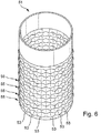
- the wall of the second section 51 instead has honeycomb-shaped bulges 53. Several layers 55 of juxtaposed bulges 53 are provided.
- only one layer may be provided, or it may have only portions of the wall, but not the entire wall surface bulges 53.
- the bulges 53 may be e.g. produced by explosion forming techniques.
- the bulges 53 cause an enlarged surface and thus increased heat dissipation away from the housing 1 by convection.
- this embodiment has the advantage that the honeycomb-shaped arrangement of the bulges 53 cause a higher rigidity of the housing 1 with respect to mechanical loads perpendicular to the longitudinal axis of the housing 1.
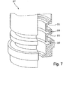
- Fig. 7 shows a further embodiment of a second portion 57.
- a plurality of circumferential grooves 59, 61 are provided in the wall of the second portion 57 of this embodiment.
- the grooves 59, 61 are arranged one above the other parallel to one another, wherein the grooves 59, 61 are arranged alternately on an inner side of the wall and an outer side of the wall, ie next to a groove 59 located on the inner side of the wall there is a groove arranged on the outer side 61, in turn, on the inside of the wall disposed groove 59 follows.
- a surface of the housing 1 is dissipated via the heat by convection radially outwards.
- the second sections 5, 29, 35, 41, 45, 51, 57 may be independent components which, for example, as in Fig. 1 represented by welds with the first and third sections 3, 7 are connected.
- the second sections 5, 29, 35, 41, 45, 51, 57 may be formed together with the first and / or the second section 3, 7 as a single component.
- the areas with reduced wall thickness or the grooves can e.g. be made by turning.
- the second sections 5, 29, 35, 41, 45, 51, 57 that even if the first section 1 at the measuring location is exposed to very high temperatures, e.g. 150 ° C, is exposed, the electronic components 19 are protected in the third section 7 from overheating. If the first section 1 is exposed to a temperature of 150.degree. C., a groove with a width of slightly more than one centimeter is already sufficient to ensure that the electronic components 19 reach a maximum temperature of 85.degree. 85 ° C is specified by most component manufacturers as the upper limit for the use of electronic components.
- a great advantage of the measuring devices according to the invention is that it can be used at high temperatures and at the same time high mechanical loads perpendicular to the longitudinal axis L of the housing 1, e.g. Loads of 1000 N, can withstand. This makes the measuring devices very versatile
Abstract
Description
Die Erfindung betrifft ein Messgerät mit einem Gehäuse, in dem elektronische Bauteile angeordnet sind.The invention relates to a measuring device with a housing in which electronic components are arranged.
Messgeräte werden in nahezu allen Industriezweigen zur Erfassung physikalischer Größen, z.B. von Füllständen oder Drücken, eingesetzt.Gauges are used in almost all industries to acquire physical quantities, e.g. of levels or pressures.
Messgeräte weisen üblicherweise eine Vorrichtung zur Erfassung der physikalischen Größe auf, die die physikalische Größe in eine elektrische Größe umwandelt und diese für eine Auswertung, Verarbeitung und/oder Anzeige zur Verfügung stellt. Hierzu sind je nach Messgerät mehr oder minder aufwendige elektronische Schaltungen im Messgerät vorgesehen, die elektronische Bauteile aufweisen.Measuring devices usually have a device for detecting the physical quantity, which converts the physical quantity into an electrical quantity and makes it available for evaluation, processing and / or display. For this purpose, depending on the meter more or less complex electronic circuits are provided in the meter, which have electronic components.
Ein Beispiel für ein Messgerät sind Füllstandsgrenzschalter, die das Erreichen eines vorbestimmten Füllstandes detektieren und z.B. als Überfüllsicherung oder als Pumpenleerlaufschutz eingesetzt werden.An example of a meter is level limit switches that detect the reaching of a predetermined level and, e.g. be used as overfill protection or as pump idle protection.
Heute sind z.B. Füllstandsgrenzschalter auf dem Markt, die ein topförmiges Gehäuse aufweisen, dessen Boden eine Membran bildet. Die Membran wird im Betrieb durch mindestens ein im Inneren des Gehäuses angeordnetes piezoelektrisches Element in Schwingungen versetzt. Auf der Membran sind z.B. in den Behälter hineinragende Schwingstäbe angeformt, die im Betrieb Schwingungen parallel zu deren Längsachse ausführen. Das aus Membran und Schwingstäben aufgebaute Schwingungsgebilde wird vorzugsweise zu Resonanzschwingungen angeregt. Die Resonanzfrequenz des Schwingungsgebildes hängt davon ab, ob die Schwingstäbe vom Füllgut bedeckt sind oder nicht. Anhand der Resonanzfrequenz lässt sich feststellen ob die Schwingstäbe vom Füllgut bedeckt sind oder nicht. Sind die Schwingstäbe vom Füllgut bedeckt, so ist ein vorbestimmter Füllstand erreicht. Der vorbestimmte Füllstand ist durch eine Einbauhöhe des Füllstandsgrenzschalters im Behälter vorgegeben.Today, for example, level limit switches are on the market, which have a cup-shaped housing whose bottom forms a membrane. The membrane is set in operation by at least one arranged inside the housing piezoelectric element in vibration. On the membrane, for example, in the container projecting oscillating rods are formed, which perform vibrations parallel to the longitudinal axis during operation. The constructed of membrane and vibrating rods vibration structure is preferably excited to resonant vibrations. The resonant frequency of the vibration structure depends on whether the oscillating rods are covered by the contents or not. On the basis of the resonant frequency can be determined whether the oscillating rods are covered by the contents or not. Are the oscillating rods covered by the contents, so a predetermined level is reached. The predetermined level is predetermined by an installation height of the level limit switch in the container.
Messgeräte werden an einem Messort, z.B. auf einem Behälter, montiert. Dabei können am Messort unter Umständen relativ hohe Temperaturen auftreten. Temperaturen in geschlossenen Behältern erreichen in vielen Industriezweigen z.B. Temperaturen von bis zu 150°C. Außerdem können in der Umgebung des Messort verhältnismäßig hohe Temperaturen, z.B. 50°C, auftreten. Elektronische Bauteile sind jedoch sehr temperaturempfindlich. In der Regel können handelsübliche elektronische Bauteile nur bei Temperaturen bis maximal 85°C eingesetzt werden.Measuring instruments are placed at a measuring location, e.g. on a container, mounted. In some cases, relatively high temperatures may occur at the measuring location. Temperatures in closed containers reach many industries, e.g. Temperatures of up to 150 ° C. In addition, relatively high temperatures, e.g. 50 ° C, occur. Electronic components are very sensitive to temperature. As a rule, commercially available electronic components can only be used at temperatures of up to 85 ° C.
Je nach Art der Anwendung und der Einbausituation am Behälter müssen die Gehäuse sehr robust ausgebildet sein. In vielen Anwendungen wird gefordert, dass das Gehäuse einer Last von maximal 1000 N quer zu einer Längsachse des Gehäuses standhalten muss, ohne dass es zu einem Bruch des Gehäuses kommt.Depending on the type of application and the installation situation on the container, the housing must be made very robust. In many applications, it is required that the housing withstand a load of at most 1000 N across a longitudinal axis of the housing without causing the housing to break.
Metallische Gehäuse sind sehr robust und lassen sich außerdem gut reinigen. Entsprechend werden in der industriellen Messtechnik bevorzugt metallische Gehäuse für Messgeräte eingesetzt.Metallic housings are very robust and are also easy to clean. Accordingly, metallic housings for measuring devices are preferably used in industrial metrology.
Metalle sind jedoch gute Wärmeleiter. Eine gute Wärmeleitung durch das Gehäuse bringt den Nachteil mit sich, dass in dem Gehäuse befindliche elektronische Bauteile eine sehr starke Erwärmung erfahren, wenn am Messort hohe Temperaturen vorherrschen.However, metals are good conductors of heat. A good heat conduction through the housing has the disadvantage that in the housing located electronic components undergo a very strong heating, if prevail at the site high temperatures.
Es ist eine Aufgabe der Erfindung ein Messgerät anzugeben, das auch bei hohen Temperaturen eingesetzt werden kann.It is an object of the invention to provide a measuring device that can be used even at high temperatures.
Hierzu besteht die Erfindung in einem Messgerät mit
- - einem Gehäuse,
- -- das einen ersten Abschnitt aufweist,
- --- an dem eine Vorrichtung zur Befestigung des Gehäuses an einem Messort vorgesehen ist,
- -- das einen zweiten Abschnitt aufweist,
- --- der an den ersten Abschnitt angrenzt, und
- -- das einen dritten Abschnitt aufweist,
- --- der an den zweiten Abschnitt angrenzt und
- --- in dem sich elektronische Bauteile befinden,
- - bei dem der zweite Abschnitt so ausgebildet ist, dass bei vorliegen eines Temperaturunterschiedes zwischen einer Umgebung des ersten Abschnitt und einer
Wärmestrom parallel zu einer Längsachse des Gehäuses
durch den zweiten Abschnitt fließt.For this purpose, the invention consists in a measuring device
- a housing,
- which has a first section,
- at which a device is provided for fastening the housing to a measuring location,
- having a second section,
- --- which is adjacent to the first section, and
- having a third section,
- --- which is adjacent to the second section and
- --- where electronic components are located,
- - Wherein the second portion is formed so that when there is a temperature difference between an environment of the first portion and a
Heat flow parallel to a longitudinal axis of the housing
flows through the second section.
Gemäß einer Weiterbildung weist eine Wand des zweiten Abschnitts mindestens einen Bereich mit reduzierter Wanddicke auf.According to a development, a wall of the second section has at least one area with reduced wall thickness.
Gemäß einer Weiterbildung ist in der Wand des zweiten Abschnitts mindestens eine umlaufende Nut vorgesehen.According to a development, at least one circumferential groove is provided in the wall of the second section.
Gemäß einer weiteren Weiterbildung sind in der Wand des zweiten Abschnitts mehrere Bereiche mit reduzierter Wanddicke nebeneinander angeordnet, die voneinander durch Stege abgetrennt sind.According to a further development, a plurality of regions with reduced wall thickness are arranged side by side in the wall of the second section, which are separated from one another by webs.
Gemäß einer weiteren Weiterbildung sind in der Wand des zweiten Abschnitts mehrere Lagen von nebeneinander angeordneten Bereichen mit reduzierter Wanddicke übereinander angeordnet, wobei benachbarte Bereiche einer Lage durch Stege voneinander getrennt sind und Stege benachbarter Lagen gegeneinander versetzt angeordnet sind.According to a further development, a plurality of layers of juxtaposed regions with reduced wall thickness are arranged one above the other in the wall of the second section, wherein adjacent regions of a layer are separated from one another by webs and webs of adjacent layers are offset from one another.
Gemäß einer weiteren Weiterbildung ist im Inneren des Gehäuses im Bereich des zweiten Abschnitts zur Erhöhung einer mechanischen Festigkeit des Gehäuses gegenüber Belastungen senkrecht zur Längsachse des Gehäuses ein Stützkörper aus einem Isolator angeordnet.According to a further development, a support body made of an insulator is arranged in the interior of the housing in the region of the second portion for increasing a mechanical strength of the housing relative to loads perpendicular to the longitudinal axis of the housing.
Gemäß einer Weiterbildung weist die Wand des zweiten Abschnitts wabenförmig angeordnete Auswölbungen auf.According to a development, the wall of the second section has honeycomb-shaped bulges.
Gemäß einer Weiterbildung sind in der Wand des zweiten Abschnitts mehrere umlaufende Nuten vorgesehen, wobei die Nuten abwechselnd auf einer Innenseite der Wand und einer Außenseite der Wand angeordnet sind.According to a development, a plurality of circumferential grooves are provided in the wall of the second portion, wherein the grooves are arranged alternately on an inner side of the wall and an outer side of the wall.
Die Erfindung und weitere Vorteile werden nun anhand der Figuren der Zeichnung, in denen sieben Ausführungsbeispiele dargestellt sind, näher erläutert; gleiche Elemente sind in den Figuren mit gleichen Bezugszeichen versehen.
- Fig. 1
- zeigt einen Schnitt durch ein Messgerät mit einer umlaufenden Nut;
- Fig. 2
- zeigt eine Ansicht eines zweiten Abschnitts mit nebeneinander auf einer Innenseite der Wand angeordneten Bereichen mit reduzierter Wandstärke;
- Fig. 3
- zeigt eine Ansicht eines zweiten Abschnitts mit nebeneinander auf einer Außenseite der Wand angeordneten Bereichen mit reduzierter Wandstärke;
- Fig. 4
- zeigt eine Ansicht eines zweiten Abschnitts mit mehreren übereinander angeordneten Lagen von nebeneinander auf einer Außenseite der Wand angeordneten Bereichen mit reduzierter Wandstärke;
- Fig. 5
- zeigt einen Schnitt durch einen zweiten Abschnitt mit durch im Schnitt kreissegmentförmige Ausnehmungen gebildeten Bereichen mit geringerer Wandstärke;
- Fig. 6
- zeigt eine Ansicht eines zweiten Abschnitts mit wabenförmig angeordneten Auswölbungen; und
- Fig. 7
- zeigt eine teilweise geschnittene Ansicht eines zweiten Abschnitts mit alternierend übereinander angeordneten innenliegenden und außenliegende Nuten.
- Fig. 1
- shows a section through a measuring device with a circumferential groove;
- Fig. 2
- shows a view of a second portion with juxtaposed on an inner side of the wall regions with reduced wall thickness;
- Fig. 3
- shows a view of a second portion with juxtaposed on an outer side of the wall regions with reduced wall thickness;
- Fig. 4
- shows a view of a second portion having a plurality of superimposed layers of juxtaposed on an outer side of the wall regions with reduced wall thickness;
- Fig. 5
- shows a section through a second portion formed by in section circular segment-shaped recesses with lower wall thickness;
- Fig. 6
- shows a view of a second portion with honeycomb arrays; and
- Fig. 7
- shows a partially sectioned view of a second portion with alternately stacked inside and outside grooves.
Bei dem dargestellten Ausführungsbeispiel handelt es sich um einen Füllstandsgrenzschalter für die Feststellung und/oder Überwachung eines vorbestimmten Füllstands in einem Behälter, wie er in der Mess- und Regeltechnik eingesetzt wird.In the illustrated embodiment, it is a level limit switch for the detection and / or monitoring of a predetermined level in a container, as used in the measurement and control technology.
Das Messgerät weist ein Gehäuse 1 aus einem Metall, z.B. einem Edelstahl, auf, das einen ersten, einen zweiten und einen dritten Abschnitt 3, 5, 7 umfasst.The measuring device comprises a housing 1 made of a metal, e.g. a stainless steel, comprising a first, a second and a
Der erste Abschnitt 3 hat die Form eines von einer Membran 9 endseitig abgeschlossenen Zylinders.The
An dem Zylinder ist eine Vorrichtung 11 zur Befestigung des Gehäuses 1 an einem Messort vorgesehen. In dem dargestellten Ausführungsbeispiel ist die Vorrichtung 11 ein Außengewinde, das an den ersten Abschnitt 3 angeformt ist. Das Gehäuse 1 ist mittels des Außengewindes in ein Gegengewinde am Messort eingeschraubt. In dem dargestellten Ausführungsbeispiel ist das Gehäuse 1 in eine Öffnung 13 eines Behälters eingeschraubt. Andere Vorrichtungen zur Befestigung, z.B. Befestigungsflansche, sind ebenfalls einsetzbar.On the cylinder, a
An der Membran 9 sind zwei voneinander beabstandete in den Behälter hineinragende Schwingstäbe 15 angeformt, die im Betrieb gegenphasige Schwingungen senkrecht zu deren Längsachse ausführen. Auf einer ins Innere des Gehäuses 1 weisenden Oberfläche der Membran 9 ist hierzu ein piezoelektrisches Element 17 angebracht, z.B. aufgeklebt, durch das die Membran 9 in Biegeschwingungen versetzbar ist.On the
Im Betrieb wird das aus Membran 9 und Schwingstäben 15 bestehende Schwingungsgebilde in Resonanzschwingungen versetzt und es wird dessen Resonanzfrequenz erfasst. Liegt die Resonanzfrequenz unterhalb eines vorgegebenen Schwellwertes, so sind die Schwingstäbe von einem Füllgut im Behälter bedeckt, liegt sie oberhalb dieses Schwellwerts, liegen die Schwingstäbe frei.In operation, consisting of
An einer membran-abgewandten Seite des ersten Abschnitts 3 grenzt der zweite Abschnitt 5 des Gehäuses 1 an. Der zweite Abschnitt 5 ist ebenfalls im wesentlichen zylindrisch.On a side of the
Der zweite Abschnitt 5 ist so ausgebildet, dass bei vorliegen eines Temperaturunterschiedes zwischen einer Umgebung des ersten Abschnitt 3 und einer Umgebung des dritten Abschnitts 7 ein geringer Wärmestrom parallel zu einer Längsachse L des Gehäuses 1 durch den zweiten Abschnitt 5 fließt. Hierdurch wird eine Wärmeübertragung vom ersten in den dritten Abschnitt 3, 7 reduziert.The
Der dritte Abschnitt 7 ist ebenfalls zylindrisch und grenzt an eine vom ersten Abschnitt 3 abgewandte Seite des zweiten Abschnitts 5 an. In dem dritten Abschnitt 7 befinden sich elektronische Bauteile 19. In dem dargestellten Ausführungsbeispiel sind die Bauteile 19 auf einer Leiterplatte 21 angeordnet, die mittels einer in
Der zweite Abschnitt 5 bewirkt einen Schutz des dritten Abschnitts 7, bzw. der darin befindlichen Bauteile 19 vor Erwärmung. Indem der zweite Abschnitt 5 so ausgebildet ist, dass bei einem Temperaturunterschied zwischen der Umgebung des ersten Abschnitt 3 und der Umgebung des dritten Abschnitts 7 nur ein geringer Wärmestrom parallel zu einer Längsachse L des Gehäuses 1 durch den zweiten Abschnitt fließt eine Erwärmung des am Messort unter Umständen sehr hohen Temperaturen ausgesetzten ersten Abschnitts 3 eine deutlich niedrigere Erwärmung des dritten Abschnitts 7, bzw. der darin befindlichen elektronischen Bauteile 19, als bei herkömmlichen Messgeräten.The
Ein geringerer Wärmestrom parallel zur Längsachse L ist physikalisch auf zwei verschiedenen Wegen erzielbar. Zum einen kann ein durch ein Temperaturgefälle zwischen dem ersten Abschnitt 3 und der Umgebung des dritten Abschnitts 7 bedingter Wärmemengenfluss reduziert werden, indem eine für diesen Wärmemengenfluss zur Verfügung stehende Querschnittsfläche reduziert wird. Zum anderen kann eine durch Konvektion vom zweiten Abschnitt 5 radial nach außen abgegebene Wärmemenge erhöht werden, indem eine hierfür zur Verfügung stehende Oberfläche erhöht wird. Beide Möglichkeiten sowie eine Kombination beider Möglichkeiten sind nachfolgend anhand der Ausführungsbeispiele näher erläutert.A smaller heat flow parallel to the longitudinal axis L can be achieved physically in two different ways. On the one hand, a heat flow due to a temperature gradient between the
Die für den Wärmemengenfluss zur Verfügung stehende Querschnittsfläche wird maßgeblich reduziert, indem eine Wand des zweiten Abschnitts 5 mindestens einen Bereich mit reduzierter Wanddicke aufweist. Die Querschnittsfläche ist proportional zur Wanddicke.The available for the flow of heat flow cross-sectional area is significantly reduced by a wall of the
Bei dem in
Eine reduzierte Wandstärke und eine breite Nut 25 führen dazu, dass das Gehäuse 1 an mechanischer Stabilität verliert. Besonders kritisch sind hierbei Belastungen, die senkrecht zur Längsachse L auf das Gehäuse 1 einwirken.A reduced wall thickness and a
Vorzugsweise ist daher, wie in
Er besteht aus einem Isolator, weil Isolatoren eine im Vergleich zu Metallen geringe Wärmeleitfähigkeit aufweisen. Der erste Abschnitt 3 weist einen geringeren Innendurchmesser auf als der zweite Abschnitt 5. Zwischen dem ersten und dem zweiten Abschnitt 3, 5 besteht somit eine Absatzfläche, auf der der Stützkörper 27 aufliegt.It consists of an insulator because insulators have a low thermal conductivity compared to metals. The
In
Die Bereiche 31 bewirken eine Reduktion des Wärmestroms parallel zur Längsachse L des Gehäuses 1. Die Abtrennung der Bereiche durch die Stege 33 verleiht dem zweiten Abschnitt 29 eine größere mechanische Stabilität, insb. auch gegenüber Belastungen senkrecht zur Längsachse L des Gehäuses 1.The
In
Während bei allen zuvor beschriebenen Ausführungsbeispielen der Wärmestrom parallel zur Längsachse L des Gehäuses 1 des zweiten Bereichs 5, 29, 35, 41, 45 durch eine geringe in dieser Richtung zur Verfügung stehende Querschnittsfläche erreicht wird, ist bei dem in
Die Wand des zweiten Abschnitts 51 weist stattdessen wabenförmig angeordnete Auswölbungen 53 auf. Dabei sind mehrere Lagen 55 von nebeneinander angeordneten Auswölbungen 53 vorgesehen.The wall of the
Alternativ kann auch nur eine Lage vorgesehen sein, oder es können nur Bereiche der Wand, nicht aber die gesamte Wandfläche Auswölbungen 53 aufweisen. Die Auswölbungen 53 können z.B. durch Explosionsumformtechniken hergestellt werden.Alternatively, only one layer may be provided, or it may have only portions of the wall, but not the entire wall surface bulges 53. The
Die Auswölbungen 53 bewirken eine vergrößerte Oberfläche und damit einen erhöhten Wärmeabtransport vom Gehäuse 1 weg durch Konvektion. Je größer die durch Konvektion abgeführte Wärmemenge ist, umso geringer ist entsprechend der Wärmemengenfluss in Richtung des dritten Abschnitts 7.The
Zusätzlich bietet diese Ausführungsform den Vorteil, dass die wabenförmige Anordnung der Auswölbungen 53 eine höhere Steifigkeit des Gehäuses 1 gegenüber mechanischen Belastungen senkrecht zur Längsachse des Gehäuses 1 bewirken.In addition, this embodiment has the advantage that the honeycomb-shaped arrangement of the
Durch die Nuten 59, 61 wird, genau wie bei dem in
Zusätzlich wird durch die alternierende Anordnung von innen und außen liegenden Nuten 59, 61 eine Oberfläche des Gehäuses 1 über die Wärme durch Konvektion radial nach außen abgeleitet wird erhöht.In addition, by the alternating arrangement of inside and
Bei den erfindungsgemäßen Messgeräten können die zweiten Abschnitte 5, 29, 35, 41, 45, 51, 57 eigenständige Bauteile sein, die z.B. wie in
Die Bereiche mit reduzierte Wandstärke bzw. die Nuten können z.B. durch Drehen hergestellt werden.The areas with reduced wall thickness or the grooves can e.g. be made by turning.
Durch die zweiten Abschnitte 5, 29, 35, 41, 45, 51, 57 wird erreicht, dass selbst dann, wenn der erste Abschnitt 1 am Messort sehr hohen Temperaturen, z.B. 150 °C, ausgesetzt ist, die elektronischen Bauteile 19 im dritten Abschnitt 7 vor einer Überhitzung geschützt sind. Ist der erste Abschnitt 1 einer Temperatur von 150 °C ausgesetzt, so genügt bereits eine Nut mit einer Breite von etwas mehr als einem Zentimeter, um zu gewährleisten, dass die elektronischen Bauteile 19 eine Temperatur von maximal 85°C erreichen. 85 °C wird von den meisten Bauteilherstellern als Temperaturobergrenze für den Einsatz von elektronischen Bauteilen angegeben.It is achieved by the
Ein großer Vorteil der erfindungsgemäßen Messgeräte besteht darin, dass sie bei hohen Temperaturen einsetzbar ist und gleichzeitig hohen mechanischen Belastungen senkrecht zur Längsachse L des Gehäuses 1, z.B. Belastungen von 1000 N, standhalten können. Damit sind die Messgeräte sehr vielseitig einsetzbarA great advantage of the measuring devices according to the invention is that it can be used at high temperatures and at the same time high mechanical loads perpendicular to the longitudinal axis L of the housing 1, e.g. Loads of 1000 N, can withstand. This makes the measuring devices very versatile
Claims (1)
dass in der Wand des zweiten Abschnitts (57) mehrere umlaufende Nuten (59, 61) vorgesehen sind, wobei die Nuten (59, 61) abwechselnd auf einer Innenseite der Wand und einer Außenseite der Wand angeordnet sind.Measuring device with
that in the wall of the second portion (57) a plurality of circumferential grooves (59, 61) are provided, wherein the grooves (59, 61) are arranged alternately on an inner side of the wall and an outer side of the wall.
Applications Claiming Priority (2)
| Application Number | Priority Date | Filing Date | Title |
|---|---|---|---|
| DE10254720A DE10254720A1 (en) | 2002-11-23 | 2002-11-23 | gauge |
| EP03775375.3A EP1563260B1 (en) | 2002-11-23 | 2003-11-20 | Housing with reduced thermal conduction for a measuring instrument |
Related Parent Applications (3)
| Application Number | Title | Priority Date | Filing Date |
|---|---|---|---|
| EP03775375.3A Division-Into EP1563260B1 (en) | 2002-11-23 | 2003-11-20 | Housing with reduced thermal conduction for a measuring instrument |
| EP03775375.3A Division EP1563260B1 (en) | 2002-11-23 | 2003-11-20 | Housing with reduced thermal conduction for a measuring instrument |
| EP03775375.3 Division | 2003-11-20 |
Publications (2)
| Publication Number | Publication Date |
|---|---|
| EP2520892A1 true EP2520892A1 (en) | 2012-11-07 |
| EP2520892B1 EP2520892B1 (en) | 2015-03-18 |
Family
ID=32240331
Family Applications (2)
| Application Number | Title | Priority Date | Filing Date |
|---|---|---|---|
| EP03775375.3A Expired - Lifetime EP1563260B1 (en) | 2002-11-23 | 2003-11-20 | Housing with reduced thermal conduction for a measuring instrument |
| EP12163268.1A Expired - Lifetime EP2520892B1 (en) | 2002-11-23 | 2003-11-20 | Measuring apparatus |
Family Applications Before (1)
| Application Number | Title | Priority Date | Filing Date |
|---|---|---|---|
| EP03775375.3A Expired - Lifetime EP1563260B1 (en) | 2002-11-23 | 2003-11-20 | Housing with reduced thermal conduction for a measuring instrument |
Country Status (6)
| Country | Link |
|---|---|
| US (1) | US20060156835A1 (en) |
| EP (2) | EP1563260B1 (en) |
| CN (2) | CN100387935C (en) |
| AU (1) | AU2003283417A1 (en) |
| DE (1) | DE10254720A1 (en) |
| WO (1) | WO2004048900A1 (en) |
Cited By (2)
| Publication number | Priority date | Publication date | Assignee | Title |
|---|---|---|---|---|
| DE102015104536A1 (en) | 2015-03-25 | 2016-09-29 | Endress + Hauser Gmbh + Co. Kg | Device for determining and / or monitoring at least one process variable |
| DE102016112309A1 (en) | 2016-07-05 | 2018-01-11 | Endress + Hauser Gmbh + Co. Kg | Device for determining and / or monitoring at least one process variable |
Families Citing this family (7)
| Publication number | Priority date | Publication date | Assignee | Title |
|---|---|---|---|---|
| DE102005014163B4 (en) * | 2005-03-29 | 2015-09-17 | Continental Automotive Gmbh | Piezoelectric actuator unit with improved thermal conductivity and fuel injector |
| DE102006019555B3 (en) * | 2006-04-27 | 2007-11-22 | Abb Patent Gmbh | Measuring transducer for use in process plant, has two containers having respective threaded connections with transformer that is made of two parts, where one part is arranged in one of containers in elastic manner by pressure spring |
| DE102006031188A1 (en) * | 2006-07-04 | 2008-01-10 | Endress + Hauser Gmbh + Co. Kg | Device for determining and / or monitoring a process variable |
| EP2159580B1 (en) * | 2008-08-26 | 2015-10-07 | Lake Shore Cryotronics, Inc. | Probe tip |
| DE102015121462A1 (en) * | 2015-12-09 | 2017-06-14 | Endress + Hauser Flowtec Ag | Connecting device for mechanically connecting an electronics housing and a transducer housing, transducer with such a connection device or thus formed field device |
| DE102019110312A1 (en) | 2019-04-18 | 2020-10-22 | Endress+Hauser Flowtec Ag | A method of manufacturing a thermal flow meter probe, thermal flow meter probe and thermal flow meter |
| US11692909B2 (en) * | 2019-08-16 | 2023-07-04 | Rosemount Aerospace. Inc. | Sensor assemblies and methods of making sensor assemblies |
Citations (4)
| Publication number | Priority date | Publication date | Assignee | Title |
|---|---|---|---|---|
| DE8216323U1 (en) * | 1982-06-04 | 1982-10-07 | Endress U. Hauser Gmbh U. Co, 7867 Maulburg | PROBE FOR CAPACITIVE MEASUREMENT OF THE LEVEL IN A CONTAINER, ESPECIALLY OF HOT FUEL |
| EP0114640A2 (en) * | 1983-01-25 | 1984-08-01 | Wickes Products, Inc. | Finned heat exchanger tube having optimized heat transfer characteristics |
| EP0547363A1 (en) * | 1991-12-14 | 1993-06-23 | Wieland-Werke Ag | Metal heat-exchanger tube for cooling viscous fluids |
| US5709029A (en) * | 1992-09-22 | 1998-01-20 | Energy Saving Concepts Limited | Manufacture of helically corrugated conduit |
Family Cites Families (25)
| Publication number | Priority date | Publication date | Assignee | Title |
|---|---|---|---|---|
| DE2134709C3 (en) * | 1971-07-12 | 1980-07-03 | Vdo Adolf Schindling Ag, 6000 Frankfurt | Housing for an electrical transducer exposed to high temperatures |
| US4092697A (en) * | 1976-12-06 | 1978-05-30 | International Business Machines Corporation | Heat transfer mechanism for integrated circuit package |
| US4421704A (en) * | 1980-07-14 | 1983-12-20 | United States Gypsum Company | Method of treatment for plaster articles to improve wear and water resistance and article of manufacture |
| JPS5829437B2 (en) * | 1980-07-24 | 1983-06-22 | トヨタ自動車株式会社 | Pipe fitting with cooling fins |
| US4575705A (en) | 1984-02-17 | 1986-03-11 | Weed Instrument Co., Inc. | Temperature probe |
| JP2640281B2 (en) * | 1990-04-07 | 1997-08-13 | 日本石油株式会社 | Water repellent composition |
| US5224383A (en) * | 1991-06-14 | 1993-07-06 | Industrial Sensors, Inc. | Melt pressure measurement and the like |
| DE4390783C1 (en) * | 1992-02-28 | 1999-11-25 | Aavid Eng Inc | Device for connecting a heat sink to an electronic circuit |
| JP2809026B2 (en) * | 1992-09-30 | 1998-10-08 | 三菱電機株式会社 | INVERTER DEVICE AND METHOD OF USING INVERTER DEVICE |
| DE4341239C2 (en) * | 1992-12-18 | 2002-03-28 | Eckart Hiss | Sicherheitsmeßfühler |
| DE4301685A1 (en) * | 1993-01-22 | 1994-07-28 | Klaus Lemcke | Dowel screw with smooth semi-circular head |
| DE9421619U1 (en) * | 1993-03-04 | 1996-05-09 | Tata Peter D | Heatsink device for solid-state components |
| JPH0719981A (en) * | 1993-06-01 | 1995-01-20 | Nippondenso Co Ltd | High-temperature pressure sensor |
| JPH08179065A (en) * | 1994-12-22 | 1996-07-12 | Advantest Corp | Heating element cooling device in vacuum chamber |
| DE19540035B4 (en) * | 1995-10-27 | 2009-02-05 | Gestra Ag | Probe with heat-insulating neck piece |
| DE19646583C2 (en) * | 1995-11-30 | 2001-04-26 | Eckart Hiss | Flow monitor |
| US5851083A (en) * | 1996-10-04 | 1998-12-22 | Rosemount Inc. | Microwave level gauge having an adapter with a thermal barrier |
| DE29704182U1 (en) * | 1997-03-07 | 1997-07-03 | Ihne & Tesch Gmbh | Arrangement for heating and cooling the extrusion cylinder of plastic processing machines |
| US5982620A (en) * | 1998-06-01 | 1999-11-09 | Asia Vital Components Co., Ltd. | CPU casing structure with improved heat dissipator anchoring configuration |
| US6066201A (en) * | 1998-11-09 | 2000-05-23 | Ergon, Inc. | Thixotropic wax emulsion compositions |
| US6251979B1 (en) * | 1998-11-18 | 2001-06-26 | Advanced Construction Materials Corp. | Strengthened, light weight wallboard and method and apparatus for making the same |
| US6287495B1 (en) * | 1998-12-23 | 2001-09-11 | Bayer Corporation | Thixotropic wood binder compositions |
| US6231656B1 (en) * | 1999-02-18 | 2001-05-15 | Allied Signal Inc. | Release agents for use in lignocellulosic processes and process for preparing molded lignocellulosic composites |
| US6165261A (en) * | 1999-06-10 | 2000-12-26 | Ergon, Inc. | Water-resistant gypsum composition |
| US6325535B1 (en) * | 1999-08-23 | 2001-12-04 | Petro-Chem Development Co., Inc. | In-situ radiant heat flux probe cooled by suction of ambient air |
-
2002
- 2002-11-23 DE DE10254720A patent/DE10254720A1/en not_active Withdrawn
-
2003
- 2003-11-20 CN CNB2003801038646A patent/CN100387935C/en not_active Expired - Fee Related
- 2003-11-20 US US10/535,912 patent/US20060156835A1/en not_active Abandoned
- 2003-11-20 EP EP03775375.3A patent/EP1563260B1/en not_active Expired - Lifetime
- 2003-11-20 AU AU2003283417A patent/AU2003283417A1/en not_active Abandoned
- 2003-11-20 CN CNB200710162653XA patent/CN100565120C/en not_active Expired - Fee Related
- 2003-11-20 WO PCT/EP2003/012982 patent/WO2004048900A1/en not_active Application Discontinuation
- 2003-11-20 EP EP12163268.1A patent/EP2520892B1/en not_active Expired - Lifetime
Patent Citations (4)
| Publication number | Priority date | Publication date | Assignee | Title |
|---|---|---|---|---|
| DE8216323U1 (en) * | 1982-06-04 | 1982-10-07 | Endress U. Hauser Gmbh U. Co, 7867 Maulburg | PROBE FOR CAPACITIVE MEASUREMENT OF THE LEVEL IN A CONTAINER, ESPECIALLY OF HOT FUEL |
| EP0114640A2 (en) * | 1983-01-25 | 1984-08-01 | Wickes Products, Inc. | Finned heat exchanger tube having optimized heat transfer characteristics |
| EP0547363A1 (en) * | 1991-12-14 | 1993-06-23 | Wieland-Werke Ag | Metal heat-exchanger tube for cooling viscous fluids |
| US5709029A (en) * | 1992-09-22 | 1998-01-20 | Energy Saving Concepts Limited | Manufacture of helically corrugated conduit |
Cited By (3)
| Publication number | Priority date | Publication date | Assignee | Title |
|---|---|---|---|---|
| DE102015104536A1 (en) | 2015-03-25 | 2016-09-29 | Endress + Hauser Gmbh + Co. Kg | Device for determining and / or monitoring at least one process variable |
| DE102016112309A1 (en) | 2016-07-05 | 2018-01-11 | Endress + Hauser Gmbh + Co. Kg | Device for determining and / or monitoring at least one process variable |
| WO2018007178A1 (en) | 2016-07-05 | 2018-01-11 | Endress+Hauser Gmbh+Co. Kg | Device for determining and/or monitoring at least one process variable |
Also Published As
| Publication number | Publication date |
|---|---|
| EP1563260B1 (en) | 2014-03-19 |
| US20060156835A1 (en) | 2006-07-20 |
| CN1714276A (en) | 2005-12-28 |
| WO2004048900A1 (en) | 2004-06-10 |
| AU2003283417A1 (en) | 2004-06-18 |
| EP1563260A1 (en) | 2005-08-17 |
| EP2520892B1 (en) | 2015-03-18 |
| CN100565120C (en) | 2009-12-02 |
| CN100387935C (en) | 2008-05-14 |
| DE10254720A1 (en) | 2004-06-03 |
| CN101196412A (en) | 2008-06-11 |
Similar Documents
| Publication | Publication Date | Title |
|---|---|---|
| EP0543006B1 (en) | Device for detecting and/or monitoring a predetermined level in a container | |
| WO2011032793A1 (en) | Fill level gauge | |
| EP2520892A1 (en) | Measuring apparatus | |
| DE1929478B2 (en) | PIEZOELECTRIC MEASURING CELL | |
| DE102006048203B4 (en) | Wiring element for an angular velocity sensor | |
| DE4233315C2 (en) | Device for fastening a housing | |
| EP2049871A1 (en) | Rotation-rate sensor | |
| DE102004032965B4 (en) | Device for aligning and centering a rod-shaped or rope-shaped surface waveguide of a field device | |
| DE19904334A1 (en) | Vibrator support structure of oscillating gyroscope | |
| DE2840286A1 (en) | VIBRATING WIRE INSTRUMENT FOR MEASURING A DIFFERENTIAL PRESSURE | |
| DE10221219B4 (en) | pressure sensor | |
| EP0926474B1 (en) | Probe | |
| DE102007038022B4 (en) | Device for determining and / or monitoring a process variable | |
| DE102007057124A1 (en) | Device for determining and / or monitoring a process variable of a medium | |
| DE3808481C2 (en) | Device for determining a certain level in a container | |
| DE19831270B4 (en) | Arrangement and method for determining and monitoring the state of stress of a fastening element | |
| DE102008054942B4 (en) | Device for determining and / or monitoring a process variable | |
| DE19746075C2 (en) | Sensor for recording the electrical conductivity of a liquid medium | |
| DE102006013255A1 (en) | Device for determining and / or monitoring a process variable | |
| DE102011121583A1 (en) | Capacitive proximity sensor for providing signal at approach of medium or conductive object, comprises internal electrode, and outer electrode, which comprises cup-shaped configuration, in which inner electrode is arranged | |
| DE102016116181A1 (en) | Single or multi-axis force measuring device with short deformation zone | |
| DE102004010912C5 (en) | Measuring probe for the determination of physical parameters on or in a boiler | |
| EP0368802A1 (en) | Apparatus for measuring accelerations, especially components of the gravitation force when measuring angles | |
| DE102006030657B4 (en) | Fluid sensor for measuring characteristic properties of a fluid | |
| DE102016113447A1 (en) | Vibration sensor and method for optimizing a piezo drive |
Legal Events
| Date | Code | Title | Description |
|---|---|---|---|
| PUAI | Public reference made under article 153(3) epc to a published international application that has entered the european phase |
Free format text: ORIGINAL CODE: 0009012 |
|
| AC | Divisional application: reference to earlier application |
Ref document number: 1563260 Country of ref document: EP Kind code of ref document: P |
|
| AK | Designated contracting states |
Kind code of ref document: A1 Designated state(s): AT BE BG CH CY CZ DE DK EE ES FI FR GB GR HU IE IT LI LU MC NL PT RO SE SI SK TR |
|
| 17P | Request for examination filed |
Effective date: 20121201 |
|
| 17Q | First examination report despatched |
Effective date: 20140514 |
|
| GRAP | Despatch of communication of intention to grant a patent |
Free format text: ORIGINAL CODE: EPIDOSNIGR1 |
|
| INTG | Intention to grant announced |
Effective date: 20141103 |
|
| GRAS | Grant fee paid |
Free format text: ORIGINAL CODE: EPIDOSNIGR3 |
|
| GRAA | (expected) grant |
Free format text: ORIGINAL CODE: 0009210 |
|
| AC | Divisional application: reference to earlier application |
Ref document number: 1563260 Country of ref document: EP Kind code of ref document: P |
|
| AK | Designated contracting states |
Kind code of ref document: B1 Designated state(s): AT BE BG CH CY CZ DE DK EE ES FI FR GB GR HU IE IT LI LU MC NL PT RO SE SI SK TR |
|
| REG | Reference to a national code |
Ref country code: GB Ref legal event code: FG4D Free format text: NOT ENGLISH |
|
| REG | Reference to a national code |
Ref country code: CH Ref legal event code: EP |
|
| REG | Reference to a national code |
Ref country code: IE Ref legal event code: FG4D Free format text: LANGUAGE OF EP DOCUMENT: GERMAN |
|
| REG | Reference to a national code |
Ref country code: AT Ref legal event code: REF Ref document number: 716838 Country of ref document: AT Kind code of ref document: T Effective date: 20150415 |
|
| REG | Reference to a national code |
Ref country code: DE Ref legal event code: R096 Ref document number: 50315228 Country of ref document: DE Effective date: 20150507 |
|
| REG | Reference to a national code |
Ref country code: NL Ref legal event code: VDEP Effective date: 20150318 |
|
| REG | Reference to a national code |
Ref country code: NL Ref legal event code: VDEP Effective date: 20150318 |
|
| PG25 | Lapsed in a contracting state [announced via postgrant information from national office to epo] |
Ref country code: SE Free format text: LAPSE BECAUSE OF FAILURE TO SUBMIT A TRANSLATION OF THE DESCRIPTION OR TO PAY THE FEE WITHIN THE PRESCRIBED TIME-LIMIT Effective date: 20150318 Ref country code: FI Free format text: LAPSE BECAUSE OF FAILURE TO SUBMIT A TRANSLATION OF THE DESCRIPTION OR TO PAY THE FEE WITHIN THE PRESCRIBED TIME-LIMIT Effective date: 20150318 |
|
| PG25 | Lapsed in a contracting state [announced via postgrant information from national office to epo] |
Ref country code: GR Free format text: LAPSE BECAUSE OF FAILURE TO SUBMIT A TRANSLATION OF THE DESCRIPTION OR TO PAY THE FEE WITHIN THE PRESCRIBED TIME-LIMIT Effective date: 20150619 |
|
| PG25 | Lapsed in a contracting state [announced via postgrant information from national office to epo] |
Ref country code: NL Free format text: LAPSE BECAUSE OF FAILURE TO SUBMIT A TRANSLATION OF THE DESCRIPTION OR TO PAY THE FEE WITHIN THE PRESCRIBED TIME-LIMIT Effective date: 20150318 |
|
| PG25 | Lapsed in a contracting state [announced via postgrant information from national office to epo] |
Ref country code: EE Free format text: LAPSE BECAUSE OF FAILURE TO SUBMIT A TRANSLATION OF THE DESCRIPTION OR TO PAY THE FEE WITHIN THE PRESCRIBED TIME-LIMIT Effective date: 20150318 Ref country code: RO Free format text: LAPSE BECAUSE OF FAILURE TO SUBMIT A TRANSLATION OF THE DESCRIPTION OR TO PAY THE FEE WITHIN THE PRESCRIBED TIME-LIMIT Effective date: 20150318 Ref country code: ES Free format text: LAPSE BECAUSE OF FAILURE TO SUBMIT A TRANSLATION OF THE DESCRIPTION OR TO PAY THE FEE WITHIN THE PRESCRIBED TIME-LIMIT Effective date: 20150318 Ref country code: PT Free format text: LAPSE BECAUSE OF FAILURE TO SUBMIT A TRANSLATION OF THE DESCRIPTION OR TO PAY THE FEE WITHIN THE PRESCRIBED TIME-LIMIT Effective date: 20150720 Ref country code: SK Free format text: LAPSE BECAUSE OF FAILURE TO SUBMIT A TRANSLATION OF THE DESCRIPTION OR TO PAY THE FEE WITHIN THE PRESCRIBED TIME-LIMIT Effective date: 20150318 Ref country code: CZ Free format text: LAPSE BECAUSE OF FAILURE TO SUBMIT A TRANSLATION OF THE DESCRIPTION OR TO PAY THE FEE WITHIN THE PRESCRIBED TIME-LIMIT Effective date: 20150318 |
|
| REG | Reference to a national code |
Ref country code: FR Ref legal event code: PLFP Year of fee payment: 13 |
|
| REG | Reference to a national code |
Ref country code: DE Ref legal event code: R097 Ref document number: 50315228 Country of ref document: DE |
|
| PLBE | No opposition filed within time limit |
Free format text: ORIGINAL CODE: 0009261 |
|
| STAA | Information on the status of an ep patent application or granted ep patent |
Free format text: STATUS: NO OPPOSITION FILED WITHIN TIME LIMIT |
|
| PG25 | Lapsed in a contracting state [announced via postgrant information from national office to epo] |
Ref country code: DK Free format text: LAPSE BECAUSE OF FAILURE TO SUBMIT A TRANSLATION OF THE DESCRIPTION OR TO PAY THE FEE WITHIN THE PRESCRIBED TIME-LIMIT Effective date: 20150318 |
|
| 26N | No opposition filed |
Effective date: 20151221 |
|
| PG25 | Lapsed in a contracting state [announced via postgrant information from national office to epo] |
Ref country code: SI Free format text: LAPSE BECAUSE OF FAILURE TO SUBMIT A TRANSLATION OF THE DESCRIPTION OR TO PAY THE FEE WITHIN THE PRESCRIBED TIME-LIMIT Effective date: 20150318 |
|
| PG25 | Lapsed in a contracting state [announced via postgrant information from national office to epo] |
Ref country code: LU Free format text: LAPSE BECAUSE OF FAILURE TO SUBMIT A TRANSLATION OF THE DESCRIPTION OR TO PAY THE FEE WITHIN THE PRESCRIBED TIME-LIMIT Effective date: 20151120 Ref country code: MC Free format text: LAPSE BECAUSE OF FAILURE TO SUBMIT A TRANSLATION OF THE DESCRIPTION OR TO PAY THE FEE WITHIN THE PRESCRIBED TIME-LIMIT Effective date: 20150318 |
|
| REG | Reference to a national code |
Ref country code: CH Ref legal event code: PL |
|
| PG25 | Lapsed in a contracting state [announced via postgrant information from national office to epo] |
Ref country code: LI Free format text: LAPSE BECAUSE OF NON-PAYMENT OF DUE FEES Effective date: 20151130 Ref country code: CH Free format text: LAPSE BECAUSE OF NON-PAYMENT OF DUE FEES Effective date: 20151130 |
|
| REG | Reference to a national code |
Ref country code: IE Ref legal event code: MM4A |
|
| PG25 | Lapsed in a contracting state [announced via postgrant information from national office to epo] |
Ref country code: IE Free format text: LAPSE BECAUSE OF NON-PAYMENT OF DUE FEES Effective date: 20151120 |
|
| REG | Reference to a national code |
Ref country code: FR Ref legal event code: PLFP Year of fee payment: 14 |
|
| REG | Reference to a national code |
Ref country code: AT Ref legal event code: MM01 Ref document number: 716838 Country of ref document: AT Kind code of ref document: T Effective date: 20151120 |
|
| PG25 | Lapsed in a contracting state [announced via postgrant information from national office to epo] |
Ref country code: AT Free format text: LAPSE BECAUSE OF NON-PAYMENT OF DUE FEES Effective date: 20151120 |
|
| PG25 | Lapsed in a contracting state [announced via postgrant information from national office to epo] |
Ref country code: BG Free format text: LAPSE BECAUSE OF FAILURE TO SUBMIT A TRANSLATION OF THE DESCRIPTION OR TO PAY THE FEE WITHIN THE PRESCRIBED TIME-LIMIT Effective date: 20150318 Ref country code: HU Free format text: LAPSE BECAUSE OF FAILURE TO SUBMIT A TRANSLATION OF THE DESCRIPTION OR TO PAY THE FEE WITHIN THE PRESCRIBED TIME-LIMIT; INVALID AB INITIO Effective date: 20031120 |
|
| PG25 | Lapsed in a contracting state [announced via postgrant information from national office to epo] |
Ref country code: CY Free format text: LAPSE BECAUSE OF FAILURE TO SUBMIT A TRANSLATION OF THE DESCRIPTION OR TO PAY THE FEE WITHIN THE PRESCRIBED TIME-LIMIT Effective date: 20150318 |
|
| PG25 | Lapsed in a contracting state [announced via postgrant information from national office to epo] |
Ref country code: BE Free format text: LAPSE BECAUSE OF NON-PAYMENT OF DUE FEES Effective date: 20151130 |
|
| REG | Reference to a national code |
Ref country code: FR Ref legal event code: PLFP Year of fee payment: 15 |
|
| REG | Reference to a national code |
Ref country code: DE Ref legal event code: R081 Ref document number: 50315228 Country of ref document: DE Owner name: ENDRESS+HAUSER SE+CO. KG, DE Free format text: FORMER OWNER: ENDRESS + HAUSER GMBH + CO. KG, 79689 MAULBURG, DE |
|
| PG25 | Lapsed in a contracting state [announced via postgrant information from national office to epo] |
Ref country code: TR Free format text: LAPSE BECAUSE OF FAILURE TO SUBMIT A TRANSLATION OF THE DESCRIPTION OR TO PAY THE FEE WITHIN THE PRESCRIBED TIME-LIMIT Effective date: 20150318 |
|
| PGFP | Annual fee paid to national office [announced via postgrant information from national office to epo] |
Ref country code: GB Payment date: 20181120 Year of fee payment: 16 Ref country code: FR Payment date: 20181123 Year of fee payment: 16 Ref country code: IT Payment date: 20181126 Year of fee payment: 16 |
|
| GBPC | Gb: european patent ceased through non-payment of renewal fee |
Effective date: 20191120 |
|
| PG25 | Lapsed in a contracting state [announced via postgrant information from national office to epo] |
Ref country code: IT Free format text: LAPSE BECAUSE OF NON-PAYMENT OF DUE FEES Effective date: 20191120 Ref country code: GB Free format text: LAPSE BECAUSE OF NON-PAYMENT OF DUE FEES Effective date: 20191120 Ref country code: FR Free format text: LAPSE BECAUSE OF NON-PAYMENT OF DUE FEES Effective date: 20191130 |
|
| PGFP | Annual fee paid to national office [announced via postgrant information from national office to epo] |
Ref country code: DE Payment date: 20201119 Year of fee payment: 18 |
|
| REG | Reference to a national code |
Ref country code: DE Ref legal event code: R119 Ref document number: 50315228 Country of ref document: DE |
|
| PG25 | Lapsed in a contracting state [announced via postgrant information from national office to epo] |
Ref country code: DE Free format text: LAPSE BECAUSE OF NON-PAYMENT OF DUE FEES Effective date: 20220601 |