EP2513875B1 - Spectral sensor for inspecting value documents - Google Patents
Spectral sensor for inspecting value documents Download PDFInfo
- Publication number
- EP2513875B1 EP2513875B1 EP10795622.9A EP10795622A EP2513875B1 EP 2513875 B1 EP2513875 B1 EP 2513875B1 EP 10795622 A EP10795622 A EP 10795622A EP 2513875 B1 EP2513875 B1 EP 2513875B1
- Authority
- EP
- European Patent Office
- Prior art keywords
- spectral
- light
- light sources
- spectral range
- value
- Prior art date
- Legal status (The legal status is an assumption and is not a legal conclusion. Google has not performed a legal analysis and makes no representation as to the accuracy of the status listed.)
- Active
Links
- 230000003595 spectral effect Effects 0.000 title claims description 276
- 238000001514 detection method Methods 0.000 claims description 68
- 238000000295 emission spectrum Methods 0.000 claims description 59
- 238000005286 illumination Methods 0.000 claims description 58
- 239000003086 colorant Substances 0.000 claims description 39
- 238000003384 imaging method Methods 0.000 claims description 36
- 238000009826 distribution Methods 0.000 claims description 32
- 230000023077 detection of light stimulus Effects 0.000 claims description 7
- 238000000034 method Methods 0.000 claims description 5
- 229910000530 Gallium indium arsenide Inorganic materials 0.000 claims description 4
- 230000003287 optical effect Effects 0.000 description 9
- 238000011156 evaluation Methods 0.000 description 7
- 238000004519 manufacturing process Methods 0.000 description 4
- 238000005259 measurement Methods 0.000 description 4
- 238000000985 reflectance spectrum Methods 0.000 description 3
- XUIMIQQOPSSXEZ-UHFFFAOYSA-N Silicon Chemical compound [Si] XUIMIQQOPSSXEZ-UHFFFAOYSA-N 0.000 description 2
- 238000012545 processing Methods 0.000 description 2
- 230000035945 sensitivity Effects 0.000 description 2
- 229910052710 silicon Inorganic materials 0.000 description 2
- 239000010703 silicon Substances 0.000 description 2
- 238000001228 spectrum Methods 0.000 description 2
- 241000282412 Homo Species 0.000 description 1
- 230000005540 biological transmission Effects 0.000 description 1
- 230000001419 dependent effect Effects 0.000 description 1
- 238000011161 development Methods 0.000 description 1
- 230000018109 developmental process Effects 0.000 description 1
- 230000004069 differentiation Effects 0.000 description 1
- 238000009429 electrical wiring Methods 0.000 description 1
- 239000011521 glass Substances 0.000 description 1
- 239000003365 glass fiber Substances 0.000 description 1
- 238000009434 installation Methods 0.000 description 1
- 229920003023 plastic Polymers 0.000 description 1
- 238000007781 pre-processing Methods 0.000 description 1
- 239000004065 semiconductor Substances 0.000 description 1
- 230000002123 temporal effect Effects 0.000 description 1
Images

Classifications
-
- G—PHYSICS
- G06—COMPUTING; CALCULATING OR COUNTING
- G06V—IMAGE OR VIDEO RECOGNITION OR UNDERSTANDING
- G06V40/00—Recognition of biometric, human-related or animal-related patterns in image or video data
- G06V40/10—Human or animal bodies, e.g. vehicle occupants or pedestrians; Body parts, e.g. hands
- G06V40/12—Fingerprints or palmprints
- G06V40/13—Sensors therefor
- G06V40/1324—Sensors therefor by using geometrical optics, e.g. using prisms
-
- G—PHYSICS
- G07—CHECKING-DEVICES
- G07D—HANDLING OF COINS OR VALUABLE PAPERS, e.g. TESTING, SORTING BY DENOMINATIONS, COUNTING, DISPENSING, CHANGING OR DEPOSITING
- G07D7/00—Testing specially adapted to determine the identity or genuineness of valuable papers or for segregating those which are unacceptable, e.g. banknotes that are alien to a currency
- G07D7/06—Testing specially adapted to determine the identity or genuineness of valuable papers or for segregating those which are unacceptable, e.g. banknotes that are alien to a currency using wave or particle radiation
- G07D7/12—Visible light, infrared or ultraviolet radiation
- G07D7/1205—Testing spectral properties
Definitions
- the invention relates to a spectral sensor for checking documents of value and a method for checking documents of value with the aid of the spectral sensor.
- sensors are usually used with which the type of documents of value is determined and / or with which the documents of value are checked for authenticity and / or for their condition.
- Such sensors are used to check documents of value such as Bank notes, checks, identification cards, credit cards, check cards, tickets, vouchers and the like are used.
- the documents of value are checked in a device for processing documents of value, in which, depending on the properties of the document of value to be checked, one or more different sensors are contained.
- the documents of value are usually scanned by the sensor during the check, the sensor and the document of value being moved relative to one another.
- the documents of value are illuminated with light sources of specific colors in order to determine the visually visible color of the document of value from the remission of the documents of value in these colors.
- these sensors correspond to the three different color receptors of the human eye, these sensors only have three color channels that e.g. are realized by red, green and blue light-emitting diodes (RGB sensors). With such optical sensors, which have only three color channels, however, no spectral intensity distribution of the light emanating from the value document can be recorded.
- the GB2366371 A discloses a lighting device for banknotes, the LEDs having six different LED groups with different peak wavelengths: one LED group in the green, one LED group in the red and four LED groups in the infrared.
- spectral sensors For recording a spectral intensity distribution, spectral sensors are known which illuminate the value documents with white light and detect the light remitted by the value documents in a spectrally resolved manner. With such Spectral sensors, a diffraction grating is used for the spectral splitting of the light remitted by the value documents.
- the spectral splitting requires a relatively long beam path from the diffraction grating to the detector line, so that such spectral sensors require a large installation space.
- the spectral range that can be detected with such a spectral sensor is relatively narrow, so that it is not possible to record a spectral intensity distribution over a wide spectral range.
- the diffraction gratings are optimized for a specific wavelength so that the reflection factor of the grating is as large as possible for light of this wavelength.
- the reflection factor of the diffraction grating drops sharply, so that only very low light intensities of the light of these wavelengths are available for detection.
- the GB2122743 A discloses checking banknotes for metameric colors, but does not describe how these metameric colors can be distinguished from one another.
- An object of the present invention is therefore to provide an improved spectral sensor for checking documents of value, which can record a spectral intensity distribution in the visually visible spectral range and / or in the near-infrared spectral range from one or more areas of a document of value and can distinguish metameric colors from one another .
- the spectral sensor has an illumination device for illuminating the document of value to be checked by the spectral sensor, imaging optics and a detection device.
- the lighting device has a multiplicity of light sources, the emission spectra of which are different from one another. The emission spectra of these light sources are in visually visible spectral range and / or in the near-infrared spectral range.
- the imaging optics images the light emitted by the lighting device onto an area of the value document to be checked. The imaging optics ensure that a clearly defined and spatially limited area of the value document to be checked can be illuminated.
- the detection device is designed to detect light which, when the spectral sensor is operated and the value document is illuminated by the illumination device, emanates from the illuminated area.
- the lighting device of the spectral sensor has a large number of different light sources, the emission spectra of which are different from one another.
- the light sources can be arranged next to one another within the lighting device, for example in a two-dimensional grid, in particular on a light source receptacle common to the light sources.
- the light sources can also be arranged in a ring, for example around the detection device.
- the imaging optics are designed to image the emission light from each of the light sources onto a document of value to be checked. The light emitted by the lighting device is imaged onto the illuminated area of the document of value by the imaging optics via a defined beam path.
- the imaging optics have, for example, one or more refractive optical elements (for example lenses) and / or diffractive and / or reflective optical elements that image the light emitted by the light sources onto the value document.
- the imaging optics are preferably designed as an imaging lens. Because the illumination light is mapped onto the value document, the illuminated area of the value document is clearly defined and spatially limited. This represents an advantage over direct illumination of the document of value by the light sources (without any intermediate lying optics) and opposite a simple light guide optics (without imaging optics), through which the light is not imaged, but is brought from the light guide to the value document without a defined beam path.
- the imaging optics are preferably arranged such that the illuminated area of the value document lies exactly or approximately in the focal point of the imaging optics. It can thereby be achieved that despite the illumination of the value document with different light sources arranged next to one another, essentially the same area of the value document to be checked can be illuminated and detected by the detection device.
- the imaging optics can be designed to illuminate a spot-shaped area on the value document, in particular a round lighting spot. However, it can also be designed to illuminate a strip-shaped area on the value document. In the first case, e.g. a radially symmetrical imaging optics can be used and in the second case a cylinder optics can be used.
- the light emitted by the light sources can be collected with the aid of collecting optics, which direct the collected light in a suitable manner onto the imaging optics and which can be a component of the lighting device.
- the light sources, the collecting optics and the imaging optics are arranged with respect to one another in this case so that the emission light from each of the light sources can be imaged by the collecting optics and the imaging optics on a value document that is to be checked by the spectral sensor when the spectral sensor is operated.
- the collecting optics is arranged between the light sources and the imaging optics in order to collect the light emitted by the light sources.
- the collecting optics can be implemented by a large number of lenses arranged next to one another, for example refractive or diffractive, lenses, each of which collects the emission light from one of the light sources.
- the lenses of the collecting optics and the imaging optics are preferably arranged and designed in such a way that the light sources are imaged out of focus on the illuminated area of the value document. It is also preferred that each light source of the lighting device is less than the focal length of the lens from the lens assigned to it.
- the lenses of the collecting optics can be designed as individual lenses or as microlenses of a microlens array.
- the collecting optics is formed by one or more light guides which are arranged between the light sources and the imaging optics.
- a common light guide can be provided for all light sources or a separate light guide for each light source.
- the emission light from the light sources is coupled into the light guide or into the light guide and the light guide guides the emission light from the light sources to the imaging optics.
- the light emerging from the light guide is imaged onto the value document by the imaging optics.
- the light guide can e.g. a glass fiber or a light guide body with a round or strip-shaped light exit surface can be used.
- the lighting device has a large number of different light sources, the emission spectra of which are in the visually visible spectral range and / or in the near-infrared spectral range and are different from one another. That is, the multitude of light sources provides a multitude of different emission spectra, the intensity maxima of which are at different wavelengths.
- each light source is the lighting device designed to emit an emission line at a certain wavelength, the spectral position of which differs from the emission lines of all other light sources of the lighting device.
- the lighting device can also have a plurality of identical light sources, for example in order to obtain sufficient lighting intensity even in a spectral range with weak light sources.
- the plurality of light sources preferably covers a section of the near-infrared spectral range in such a way that the spectral sensor can record a spectral intensity distribution in the section of the near-infrared spectral range by detecting the measured values.
- the light sources of the lighting device are selected, for example, so that the spectral sensor can record a spectral intensity distribution in the near-infrared spectral range that extends from the visually visible spectral range to the near-infrared spectral range, for example from the visually visible spectral range up to at least a wavelength of 1000 nm , preferably up to at least a wavelength of 1200 nm.
- the multitude of light sources also covers a section of the visually visible spectral range in such a way that the spectral sensor can record a spectral intensity distribution of the detected light in the section of the visually visible spectral range.
- the multitude of light sources covers the red spectral range and / or the green spectral range and / or the blue spectral range in such a way that at least two different emission spectra of the light sources lie in the respective spectral range and / or it covers the near-infrared spectral range of 750 nm to 1000 nm in such a way that there are at least three different emission spectra of the light sources in the respective spectral range.
- the lighting device can also have one or more light sources whose emission spectrum is in the ultraviolet spectral range.
- Light-emitting diodes for example light-emitting diodes (LED), in particular semiconductor light-emitting diodes or organic light-emitting diodes (OLED), and / or laser diodes, in particular vertical cavity surface emitting laser (VCSEL), are preferably used as light sources.
- LED light-emitting diodes
- OLED organic light-emitting diodes
- laser diodes in particular vertical cavity surface emitting laser (VCSEL)
- the light sources are switched on and off one after the other, around an area of the value document with an illumination sequence to illuminate from light pulses with different emission spectra.
- the detection device is designed to detect light which, when the spectral sensor is operated, emanates from the area of the document of value illuminated with the illumination sequence.
- a measured value is detected for each of the light pulses of the lighting sequence in order to record a spectral intensity distribution of the detected light.
- the detected measured values each correspond to the light intensity that is detected during illumination with one of the light pulses of the illumination sequence.
- the spectral intensity distribution of the detected light is derived from the detected measured values.
- the lighting sequence is repeated periodically.
- the value document is illuminated by the same lighting sequence at least over a partial area of the value document to be checked. In other subregions, the value document can be illuminated by a different illumination sequence.
- the lighting sequences can be selected as a function of the value document to be checked.
- a spectral intensity distribution of the light emanating from the value document can already be determined from the measured values that are detected during a single lighting sequence.
- measured values of the various lighting sequences can also be combined, preferably measured values of at least two successive lighting sequences. For example, at least two measured values that are detected in successive lighting sequences when illuminating with the same light source are combined to form a resulting measured value.
- the value documents to be checked are transported past the spectral sensor at a transport speed.
- the lighting sequence preferably has a duration which is coordinated with the transport speed of the document of value to be checked such that all light pulses that are emitted by the light sources during the lighting sequence illuminate almost the same area of the document of value.
- the area of the value document illuminated by the first light pulse of the illumination sequence and the area of the value document illuminated by the last light pulse of the same illumination sequence have an overlap of at least 75%. That is, for all light pulses of the same lighting sequence, the areas of the illuminated areas that are successively illuminated by these light pulses, despite the movement of the document of value during the lighting sequence, are at least 75% identical.
- the spectral sensor is preferably not designed to check the entire surface of the document of value, but rather to check the document of value in one or more tracks on the document of value.
- areas of value document which are not checked by the spectral sensor are arranged between the tracks.
- the areas illuminated for checking the value document form traces which run parallel to one another and along the transport direction of the value document.
- the traces are discretely distributed on the value document.
- at least one lighting device, imaging optics and detection device are provided as described above. The lighting sequences preferably follow one another so quickly that the value document is checked quasi continuously along each of the tracks.
- the section of the near-infrared spectral range that the light sources cover includes at least the wavelengths from 750 nm to 1000 nm and can also include the wavelengths from 1000 nm to 1600 nm, optionally also wavelengths above 1600 nm.
- the spectral sensor is preferably equipped with light sources which cover the spectral range above 1000 nm. This is because the spectral sensor can then also advantageously record a spectral intensity distribution in this long-wave spectral range for which the previously customary spectral sensors that use silicon-based detectors are not suitable.
- the section of the visually visible spectral range which the light sources cover can be, for example, the spectral range belonging to a specific color, for example the spectral range perceived as red by the human eye.
- the light sources can, however, also cover two or more colors, so that the spectral intensity distribution extends over two or more colors, for example over the green and the red spectral range.
- the emission spectra of the light sources of the lighting device include, for example, at least 5 different emission spectra in the visually visible spectral range.
- the section of the visually visible spectral range which the light sources cover can, however, also be the entire visually visible spectral range.
- the spectral sensitivity of the eye is based on only three color channels. That is why there are colors that are different from one another, but trigger the same color impression in the human eye. Such colors, which have different spectral properties but look the same to humans under the same lighting conditions, are known as metameric colors. Previous sensors that - like the human eye - only have three color channels, such as RGB sensors, cannot distinguish between metameric colors.
- the spectral sensor according to the invention is, however, designed to distinguish metameric colors.
- the emission spectra of the light sources are selected in such a way that metameric colors are based on those recorded by the spectral sensor spectral intensity distributions, can be distinguished from one another.
- the spectral sensor can each record a spectral intensity distribution for two metameric colors that are contained on the same or on different documents of value, so that they can be compared with one another and their differences can be determined.
- the emission spectra of the light sources are preferably spectrally located in such a way that metameric colors, which may be contained in the illuminated area of the document of value, can be distinguished from one another on the basis of the respective spectral intensity distribution that the spectral sensor uses when detecting the metameric color emanating from Can absorb light.
- the multitude of light sources covers the red spectral range and / or the green spectral range and / or the blue spectral range and / or the near-infrared spectral range from 750 nm to 1000 nm in such a way that metameric colors that are contained in the illuminated area are generated by the spectral sensor can, can be distinguished from one another on the basis of the spectral intensity distribution that the spectral sensor picks up when detecting the light emanating from the metameric color.
- the light sources are selected so that at least two different emission spectra of the light sources lie within the spectral range of this color channel.
- the spectral sensor can distinguish many different metameric colors from one another, it is preferred to also cover further color channels (for example green, blue) by at least two different emission spectra in each case.
- further color channels for example green, blue
- the plurality of light sources be red Cover the spectral range and / or the green spectral range and / or the blue spectral range in such a way that at least two different emission spectra of the light sources lie in the respective spectral range.
- the multitude of light sources covers the near-infrared spectral range from 750 nm to 1000 nm and optionally also the near-infrared spectral range from 1000 nm to 1600 nm in such a way that at least three, preferably at least five, different ones in the respective spectral range Emission spectra of the light sources.
- the emission spectra of at least three, in particular of at least five, of the light sources that are spectrally adjacent to one another overlap spectrally and / or each have emission maxima which are different from one another and whose spectral distance is at most 60 nm.
- each of the emission spectra of the light sources of the lighting device spectrally overlaps with at least one of the emission spectra of one of the other spectrally adjacent light sources of the lighting device.
- the detection device preferably has a spectral sensitivity which is spectrally broad enough that the emission light from each of the light sources of the lighting device can be detected by the detection device.
- the detection device is designed at least for the detection of light in the visually visible spectral range and for the detection of light in the adjacent near-infrared spectral range up to at least 1000 nm.
- the silicon-based detection devices commonly used are suitable for the visually visible spectral range, but not for the spectral range above 1000 nm. It is therefore particularly advantageous to equip the spectral sensor with a detection device equip, which is designed both for the detection of light in the visually visible spectral range and the near-infrared spectral range up to over 1000 nm.
- the spectral sensor has an InGaAs photodetector as a detection device, which is designed both for the detection of light in the near-infrared spectral range, in particular for the detection of wavelengths above 1000 nm, and for the detection of light in the visually visible spectral range.
- the spectral sensor can also contain several identical detection devices, e.g. to capture the reflected light over a larger angular range.
- the spectral sensor can also have several different detection devices, e.g. to expand the spectral range that can be recorded with the spectral sensor.
- the various detection devices can be arranged next to one another or one behind the other, e.g. in the form of a sandwich structure.
- the measured values recorded by the detection device are evaluated by an evaluation device, which can be part of the spectral sensor or is also formed by an external evaluation device. At least one preprocessing of the measured values is preferably already carried out by the spectral sensor, in particular by an internal evaluation device of the spectral sensor. Further evaluation can also be carried out by the internal evaluation device or alternatively by a central evaluation device of the device in which the spectral sensor is installed.
- Detection optics can be arranged in front of the detection device, by means of which light emanating from the document of value is collected and directed onto a light-sensitive area of the detection device.
- the detection optics include e.g. one or more refractive or diffractive optical elements or mirrors.
- the detection optics and the detection device are designed and arranged such that, when the spectral sensor is operated, of the light emanating from the illuminated area, only light from a detection area of the value document is detected which is arranged completely within the illuminated area. Because the detection area is arranged completely within the illuminated area, it is achieved that the detected light intensity is insensitive to fluttering movements of the value document which can occur when the value document is being transported. As a result, the spectral sensor also becomes tolerant of possible position fluctuations of the lighting device, the imaging optics, the detection device or the detection optics, which can occur during the manufacture or assembly of the spectral sensor.
- the detection area is preferably arranged completely within a homogeneously illuminated section of the illuminated area. In the homogeneously illuminated section, the intensity of the illumination is preferably distributed homogeneously for all light pulses of the illumination sequence.
- a control device is provided for the spectral sensor which is set up to switch the light sources of the lighting device on and off one after the other in order to illuminate the value document one after the other with different emission spectra of the different light sources.
- the control device can be designed as a component of the spectral sensor, but it can also be designed as an external control device, for example as a component of a device for processing documents of value, in which the spectral sensor is installed.
- the control device is set up to include the lighting device of the spectral sensor, in particular the light sources, and the detection device of the spectral sensor. When the spectral sensor is operated, the control device switches the light sources on and off again one after the other, for example so that precisely one of the light sources is switched on at any point in time.
- control device causes the detection device to record a measured value during the switched-on phase of the light sources which corresponds to the light intensity emanating from the value document. Since the detection device records a measured value in each case synchronously with the illumination by the light sources, the light intensity emanating from the value document is detected for those wavelengths that are specified by the emission spectrum of the respective light source.
- the lighting sequences are defined which are used to check the value document, in particular which of the light sources are switched on and off for illuminating the value document.
- the control device provided for the spectral sensor can already be configured during the manufacture of the spectral sensor. However, it can be provided that the configuration of the control device is carried out only after the completion of the spectral sensor. Furthermore, it can be provided that the configuration of the control device can also be changed after the spectral sensor has been started up. Such a reconfiguration after commissioning can be carried out, for example, by the manufacturer of the spectral sensor or by an operator of the spectral sensor or of the device in which the spectral sensor is installed.
- the control of the detection device may also be necessary to adapt the control of the detection device to the control of the lighting device, for example if the number of measurement switched on and off light sources is changed.
- the evaluation device that is used to evaluate the detected measured values must also be adapted to the changed configuration of the control device, for example if other light sources are to be used to check the value document.
- the spectral sensor preferably also has a housing in which the lighting device, the imaging optics and the detection device, optionally also the control device and detection optics, are arranged.
- Another aspect of the invention is a method for checking documents of value that can be carried out with the aid of the above-described spectral sensor.
- the value document is transported past the spectral sensor at a transport speed.
- the value document is illuminated by an illumination device which has a multiplicity of light sources, the emission spectra of which are different from one another.
- the plurality of light sources are switched on and off one after the other when illuminating the document of value in order to illuminate an area of the document of value with an illumination sequence of light pulses with different emission spectra.
- the light emitted by the lighting device is imaged on the illuminated area of the value document with the aid of imaging optics.
- the light emitted by the light sources is preferably collected with the aid of collecting optics, which are arranged between the light sources and the imaging optics.
- the light emanating from the illuminated area of the value document is detected.
- a measured value is detected for each of the light pulses of the lighting sequence in order to obtain a spectral intensity distribution of the area emanating from the illuminated area Absorb light.
- the multitude of light sources cover at least a section of the visually visible spectral range and / or the near-infrared spectral range in such a way that a spectral intensity distribution in the section of the visually visible spectral range and / or the near-infrared spectral range is recorded by detecting the measured values.
- the multitude of light sources cover the red spectral range and / or the green spectral range and / or the blue spectral range in such a way that at least two different emission spectra of the light sources lie in the respective spectral range and / or they cover the near-infrared spectral range of 750 nm to 1000 nm in such a way that there are at least three different emission spectra of the light sources in the respective spectral range, the emission spectra of at least three of the light sources that are spectrally adjacent to one another spectrally overlap and / or each have different emission maxima, their spectral distance is at most 60 nm.
- the lighting device has a light source receptacle on which a plurality of light source positions are provided, each of which is designed to receive a light source.
- the light source positions are arranged next to one another on the light source holder and are defined by a large number of individual depressions, through which a chip-shaped light source can be accommodated.
- the light source positions can, however, also be defined by elevations and / or by electrical contact surfaces which the light source receptacle can have, which are designed to accommodate a chip-shaped light source.
- the lighting device of the spectral sensor can have collecting optics.
- the collecting optics are designed, for example, as a microlens array that contains a large number of microlenses.
- the microlens array and the light source receptacle are arranged with respect to one another in such a way that each of the light sources arranged on the light source receptacle is assigned precisely one of the microlenses.
- the emission light from each of the light sources is collected by precisely one microlens of the microlens array.
- the microlens assigned to the respective light source allows the emission light from the light sources to be collected with high efficiency.
- the microlenses are arranged in order to obtain a one-to-one assignment between the microlenses and the light sources in the microlens array and the arrangement of the light sources on the light source receptacle is the same.
- the microlenses and the light sources are arranged in the same two-dimensional grid.
- the microlens array is preferably designed as a one-piece body which has fastening means which are an integral part of the one-piece body.
- the light source receptacle has a counterpart that matches the fastening means of the microlens array.
- microlens array results in great advantages compared to an illumination device in which an individual lens is used for each light source. Because in this case an individual holder would have to be provided for each of the individual lenses and the exact positioning relative to the respective light source would have to be ensured when the individual lenses are attached. It may be necessary here for the exact position and / or orientation of the individual lenses to be adjusted subsequently. In contrast, when using a microlens array which has exactly one microlens for each light source, a single precise positioning is sufficient. This positioning can take place using the fastening means of the microlens array, which are connected to the corresponding counterparts of the light source receptacle. The production of the spectral sensor can therefore take place much more simply and without adjustment.
- microlens array In contrast to the implementation of corresponding lighting with individual lenses, which must be held individually and gaps always remain when they are arranged, in the microlens array there is also no or only a minimal gap between the individual microlenses. Since the microlens array is designed as a one-piece body, the microlenses can merge directly into one another. The microlens array can therefore quasi achieve a comprehensive collection of light will. The microlens array forms a lighting device that has a high light collection efficiency and is very compact.
- the spectral sensor for checking value documents is explained below using the example of a reflectance sensor.
- the spectral sensor according to the invention can, however, also be designed as a transmission sensor.
- the detection device will be arranged opposite to the illumination device, so that the illumination light transmitted through the value document is detected.
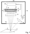
- FIG. 11 shows an example of a spectral sensor 100 which is designed to check documents of value 1 that are transported past the spectral sensor 100.
- the spectral sensor 100 has an illuminating device 50 which is equipped with a multitude of light sources 15 with a multitude of different emission spectra.
- the illuminating light emitted by the illuminating device 50 is imaged onto the value document 1 by means of a collecting optics and an imaging lens 25.
- the collecting optics 20 is designed as a microlens array 20.
- other optical components such as lens systems, one or more diffractive optical components, e.g.
- Fresnel lenses, or imaging mirrors can also be used as imaging optics, as an alternative to the imaging lens 25.
- portions of the illuminating light are remitted from the document of value 1.
- the light remitted by the document of value 1 is detected with the aid of a detection device 30 which has a light-sensitive area 31.
- the detection device 30 can be formed, for example, by an InGaAs photodiode or an InGaAs phototransistor.
- detection optics 35 Arranged in front of the detection device 30 are detection optics 35 by means of which the light reflected from the value document 1 is collected and directed onto the light-sensitive area 31.
- the illuminating light is imaged perpendicularly onto the document of value 1 and the detection device 30 detects the light remitted at an oblique angle.
- the illumination can also take place at an oblique angle and the detection device 30 can detect the light reflected in the vertical direction or the light reflected in the oblique direction.
- the lighting device 50 comprises a light source receptacle 10, on which a plurality of light source positions 11 are provided, each of which is designed to receive a light source 15.
- the light source receptacle 10 is designed, for example, as a printed circuit board and has an electrical wiring structure (not shown) which is required to operate the light sources 15 and which allows each individual light source 15 to be controlled selectively.
- the light source positions 11 are formed by depressions in the light source receptacle 10, in each of which a light source 15 is attached.
- some or all of the light source positions 11 are each provided with a light source 15. LEDs and / or OLEDs and / or VCSELs, for example, are used as light sources 15.
- the microlens array 20 of the lighting device has a multiplicity of microlenses 21.
- the light source receptacle 10 and the microlens array are matched to one another such that precisely one of the microlenses 21 is assigned to each of the light source positions 11.
- the microlenses 21 are arranged within the microlens array 20 in the same grid as the light source positions 11 are arranged on the light source receptacle 10.
- the light emitted by the individual light sources 15 is collected by the microlens 21 arranged above the respective light source 15.
- the microlens array 20 is designed as a one-piece body and is formed, for example, by a glass body or a transparent plastic body.
- the diameter of the individual microlenses is, for example, in the ⁇ m range or in the mm range.
- the body of the microlens array 20 is equipped with fastening pins 22 which are inserted into matching holes in the light source receptacle 10.
- the optimal position of the microlens array 20 relative to the light sources 15 is automatically achieved. During the production of the spectral sensor 100, therefore, no adjustment of the lighting device 50 is required.
- the spectral sensor 100 has a housing 90, on the underside of which a transparent window 101 is arranged.
- the light emitted by the lighting device 50 is directed through the window 101 onto a document of value 1 to be checked, which is transported past the spectral sensor 100 along a transport direction T.
- the lighting device 50, in particular the light sources 15, and the detection device 30 are controlled by a control device 60 which, in this example, is arranged within the housing 90.
- the control device 60 switches the light sources 15 on and off again one after the other, for example in such a way that exactly one light source 15 is switched on at each point in time.
- the detection device 30 in each case records a measured value which corresponds to the light intensity remitted by the value document 1.
- the value document 1 is illuminated one after the other with the different emission spectra of the different light sources 15. Since the detection device 30 detects a measured value in each case synchronously with the illumination by the light sources 15, the light intensity remitted by the value document 1 is detected for the different emission spectra of the light sources 15.
- the light sources 15 have a large number of different emission spectra.
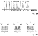
- Figure 2a shows the emission spectra E1-E12 of the light sources for an example in which the lighting device has twelve light sources 15, the emission spectra of which are partly in the visually visible spectral range and partly in the near-infrared spectral range.
- the emission maxima E1-E12 of all twelve light sources 15 are at different wavelengths ⁇ 1- ⁇ 12.
- the spectral distances between the individual emission maxima at ⁇ 4- ⁇ 8 are each less than 60 nm in this example.
- the emission spectra E10, E11 and E12 of the spectrally adjacent light sources at ⁇ 10, ⁇ 11 and ⁇ 12 spectrally overlap one another.
- the control device 60 controls the light sources 15 in such a way that the lighting sequence B1, with which the light sources 15 are switched on and off, is repeated periodically.
- Figure 2b shows an example of a lighting sequence B1, which consists of 12 light pulses P1-P12 and is repeated periodically (B2, B3, ).
- the control device 60 can be programmed such that each light source 15 of the lighting device 50 is switched on and off exactly once during each of the lighting sequences B1, B2, B3.
- the same light source 15 can also be activated several times per lighting sequence, for example in order to compensate for the low intensity of a light source 15 with a weak intensity by making multiple measurements.
- An illumination sequence can either contain the control of all light sources 15 present in the illumination device 50 or only a subset of the existing light sources 15.
- the next lighting sequence B2 starts, in which a measured value is recorded again under lighting with each emission spectrum E1-E12 provided for the measurement, etc.
- the measured values obtained during an illumination sequence supply the spectral dependence of the remission of the respective detection area on the value document.
- several measured values can be recorded in consecutive Lighting sequences that are detected when lighting with the same light source are combined to form a resulting measured value.
- the measured value that is detected during illumination with the first light pulse P1 of the first illumination sequence B1 and the measured value that is detected during illumination with the first light pulse P1 of the second illumination sequence B2 can be combined to form a resulting measured value.
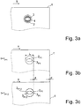
- Figure 3a shows a partial area of the document of value 1 on which the area 2 illuminated by the lighting device 50 is shown.
- the light pulses P1-P12 of the lighting sequence B1 illuminate a section 4 of the lighting area 2 with a homogeneous light intensity.
- the detection area 3 is shown, which is arranged completely within the homogeneously illuminated section 4 of the illumination area 2.
- the duration ⁇ t of the lighting sequences B1, B2, B3, ... is matched to the transport speed of the document of value 1 in such a way that at least approximately the reflected light from the same detection area 3 on the document of value 1 is detected by the various measured values of an illumination sequence.
- the Figures 3b and 3c a partial area of the value document 1 at two different times t P1 and t P12 .
- the homogeneously illuminated section 4 is in the Figures 3b, 3c not shown.
- the value document 1 is illuminated by the first light pulse P1 of the illumination sequence B1, the area illuminated in this case being denoted by 2 P1 and the associated detection area by 3 P1 , cf.
- Figure 3b the area illuminated in this case being denoted by 2 P1 and the associated detection area by 3 P1 , cf.
- the document of value 1 moves from time t P1 to time t P12 by a distance d along the transport direction T.
- the document of value 1 becomes the by the last light pulse P12 Illumination sequence B1 illuminated, the illuminated area being designated with 2 P12 and the associated detection area with 3 P12 , cf.
- Figure 3c the area 2 P1 of the document of value 1 illuminated by the first light pulse P1 is also sketched again, which is offset by the distance d from the illuminated area 2 P12 . In comparison to the length L of the illuminated area, however, the distance d is very short.
- the positions of the illuminated area 2 P12 and of the detection area 3 P12 on the value document are therefore only slightly offset compared to the positions of the illuminated area 2 P1 and of the detection area 3 P1 on the value document 1.
- the distance is opposite the length L of the illuminated area d, which the value document 1 covers from the beginning to the end of the same lighting sequence, so short that the two illuminated areas 2 P1 and 2 P12 overlap by at least 75% in terms of area.
- Figure 4a shows an example of a remission spectrum (dashed line) of a first color C1.
- the symbols x mark the measured values which a spectral sensor detects when recording the spectral intensity distribution of the first color C1.
- this spectral sensor uses light sources of ten different wavelengths ⁇ 1- ⁇ 10, five of which are in the red spectral range (RED) ( ⁇ 4- ⁇ 8).
- RED red spectral range
- Figure 4b In addition to the reflectance spectrum of the first color C1, the reflectance spectrum of a second color C2 is also shown (solid line) as well as the measured values labeled with the symbol o, which the spectral sensor detects when recording the spectral intensity distribution of the second color C2.
- the first color C1 and the second color C2 are metameric colors to one another, their reflectance spectra only differing from one another in the red spectral range and otherwise being identical.
- Previous RGB sensors can detect reflected light in the red spectral range, but they detect the entire red color channel RED integrally. This means that the total intensity of the reflected light lying in the red spectral range is detected, regardless of its spectral distribution within the red spectral range.
- An RGB sensor can only distinguish between two colors if the two colors differ in their overall intensity, which the RGB sensor detects from the respective color in one of its color channels. Since the two remission spectra of colors C1 and C2, viewed over the red spectral range, have the same area (cf. Figure 4b ), the RGB sensor, which integrally measures the red spectral range RED, would detect the same total intensity of the two colors in the red. As a result, the RGB sensor cannot distinguish the two metameric colors C1 and C2 from one another.
- the inventive spectral sensor can, however, distinguish metameric colors from one another on the basis of the spectral intensity distribution that the spectral sensor records of these colors within a color channel.
- the spectral sensor can distinguish the two colors C1 and C2 by comparing the spectral intensity distribution within the red spectral range, in particular by comparing the five measured values (x and o), which it detects at the wavelengths ⁇ 4 to ⁇ 8.
Landscapes
- Physics & Mathematics (AREA)
- Engineering & Computer Science (AREA)
- Health & Medical Sciences (AREA)
- General Health & Medical Sciences (AREA)
- Toxicology (AREA)
- General Physics & Mathematics (AREA)
- Spectroscopy & Molecular Physics (AREA)
- Human Computer Interaction (AREA)
- Optics & Photonics (AREA)
- Multimedia (AREA)
- Theoretical Computer Science (AREA)
- Facsimile Scanning Arrangements (AREA)
- Inspection Of Paper Currency And Valuable Securities (AREA)
- Investigating Materials By The Use Of Optical Means Adapted For Particular Applications (AREA)
- Spectrometry And Color Measurement (AREA)
- Image Input (AREA)
- Investigating Or Analysing Materials By Optical Means (AREA)
- Photometry And Measurement Of Optical Pulse Characteristics (AREA)
Description
Die Erfindung betrifft einen Spektralsensor zur Prüfung von Wertdokumenten und ein Verfahren zur Prüfung von Wertdokumenten mit Hilfe des Spektralsensors.The invention relates to a spectral sensor for checking documents of value and a method for checking documents of value with the aid of the spectral sensor.
Zur Prüfung von Wertdokumenten werden üblicherweise Sensoren verwendet, mit denen die Art der Wertdokumente bestimmt wird und/oder mit denen die Wertdokumente auf Echtheit und/oder auf ihren Zustand geprüft werden. Derartige Sensoren werden zur Prüfung von Wertdokumenten wie z.B. Banknoten, Schecks, Ausweisen, Kreditkarten, Scheckkarten, Tickets, Gutscheinen und dergleichen verwendet. Die Prüfung der Wertdokumente erfolgt in einer Vorrichtung zur Wertdokumentbearbeitung, in der, je nach den zu prüfenden Wertdokumenteigenschaften, einer oder mehrere unterschiedliche Sensoren enthalten sind. Üblicherweise werden die Wertdokumente bei der Prüfung durch den Sensor abgetastet, wobei der Sensor und das Wertdokument relativ zueinander bewegt werden.To check documents of value, sensors are usually used with which the type of documents of value is determined and / or with which the documents of value are checked for authenticity and / or for their condition. Such sensors are used to check documents of value such as Bank notes, checks, identification cards, credit cards, check cards, tickets, vouchers and the like are used. The documents of value are checked in a device for processing documents of value, in which, depending on the properties of the document of value to be checked, one or more different sensors are contained. The documents of value are usually scanned by the sensor during the check, the sensor and the document of value being moved relative to one another.
Bei einer Vielzahl von Sensoren werden die Wertdokumente mit Lichtquellen bestimmter Farben beleuchtet, um aus der Remission der Wertdokumente bei diesen Farben die visuell sichtbare Farbe des Wertdokuments zu ermitteln. Entsprechend den drei verschiedenen Farbrezeptoren des menschlichen Auges haben diese Sensoren nur drei Farbkanäle, die z.B. durch rote, grüne und blaue Leuchtdioden realisiert sind (RGB-Sensoren). Mit derartigen optischen Sensoren, die nur drei Farbkanäle aufweisen, kann jedoch keine spektrale Intensitätsverteilung des von dem Wertdokument ausgehenden Lichts aufgenommen werden.In the case of a large number of sensors, the documents of value are illuminated with light sources of specific colors in order to determine the visually visible color of the document of value from the remission of the documents of value in these colors. Corresponding to the three different color receptors of the human eye, these sensors only have three color channels that e.g. are realized by red, green and blue light-emitting diodes (RGB sensors). With such optical sensors, which have only three color channels, however, no spectral intensity distribution of the light emanating from the value document can be recorded.
Die
Zur Aufnahme einer spektralen Intensitätsverteilung sind Spektralsensoren bekannt, die die Wertdokumente mit Weißlicht beleuchten und das von den Wertdokumenten remittierte Licht spektral aufgelöst detektieren. Bei derartigen Spektralsensoren wird ein Beugungsgitter für die spektrale Aufspaltung des von den Wertdokumenten remittierten Lichts verwendet. Die spektrale Aufspaltung erfordert jedoch einen relativ langen Strahlengang vom Beugungsgitter bis zur Detektorzeile, so dass derartige Spektralsensoren einen großen Bauraum benötigen. Außerdem ist der mit einem solchen Spektralsensor erfassbare Spektralbereich relativ schmal, so dass sich damit keine spektrale Intensitätsverteilung über einen breiten Spektralbereich aufnehmen lässt. Denn die Beugungsgitter sind auf eine bestimmte Wellenlänge optimiert, so dass der Reflexionsfaktor des Gitters für Licht dieser Wellenlänge möglichst groß ist. Für davon abweichende Wellenlängen fällt der Reflexionsfaktor des Beugungsgitters dagegen stark ab, so dass von dem Licht dieser Wellenlängen nur sehr geringe Lichtintensitäten zur Detektion zur Verfügung stehen.For recording a spectral intensity distribution, spectral sensors are known which illuminate the value documents with white light and detect the light remitted by the value documents in a spectrally resolved manner. With such Spectral sensors, a diffraction grating is used for the spectral splitting of the light remitted by the value documents. The spectral splitting, however, requires a relatively long beam path from the diffraction grating to the detector line, so that such spectral sensors require a large installation space. In addition, the spectral range that can be detected with such a spectral sensor is relatively narrow, so that it is not possible to record a spectral intensity distribution over a wide spectral range. This is because the diffraction gratings are optimized for a specific wavelength so that the reflection factor of the grating is as large as possible for light of this wavelength. For wavelengths that deviate therefrom, on the other hand, the reflection factor of the diffraction grating drops sharply, so that only very low light intensities of the light of these wavelengths are available for detection.
Die
Eine Aufgabe der vorliegenden Erfindung ist es daher, einen verbesserten Spektralsensor zur Prüfung von Wertdokumenten bereit zu stellen, der von einem oder mehreren Bereichen eines Wertdokuments eine spektrale Intensitätsverteilung im visuell sichtbaren Spektralbereich und/oder im Nahinfrarot-Spektralbereich aufnehmen kann und metamere Farben voneinander unterscheiden kann.An object of the present invention is therefore to provide an improved spectral sensor for checking documents of value, which can record a spectral intensity distribution in the visually visible spectral range and / or in the near-infrared spectral range from one or more areas of a document of value and can distinguish metameric colors from one another .
Diese Aufgabe wird durch die Gegenstände der unabhängigen Ansprüche gelöst. In davon abhängigen Ansprüchen sind vorteilhafte Weiterbildungen und Ausgestaltungen der Erfindung angegeben.This object is achieved by the subjects of the independent claims. In the dependent claims, advantageous developments and refinements of the invention are specified.
Der Spektralsensor weist eine Beleuchtungseinrichtung zum Beleuchten des durch den Spektralsensor zu prüfenden Wertdokuments, eine Abbildungsoptik und eine Detektionseinrichtung auf. Die Beleuchtungseinrichtung weist eine Vielzahl von Lichtquellen auf, deren Emissionsspektren voneinander verschieden sind. Die Emissionsspektren dieser Lichtquellen liegen im visuell sichtbaren Spektralbereich und/oder im Nahinfrarot-Spektralbereich. Die Abbildungsoptik bildet das von der Beleuchtungseinrichtung ausgesendete Licht auf einen Bereich des zu prüfenden Wertdokuments ab. Durch die Abbildungsoptik wird erreicht, dass ein klar definierter und räumlich begrenzter Bereich des zu prüfenden Wertdokuments beleuchtet werden kann. Die Detektionseinrichtung ist zum Detektieren von Licht ausgebildet, das, beim Betreiben des Spektralsensors, wenn das Wertdokument durch die Beleuchtungseinrichtung beleuchtet wird, von dem beleuchteten Bereich ausgeht.The spectral sensor has an illumination device for illuminating the document of value to be checked by the spectral sensor, imaging optics and a detection device. The lighting device has a multiplicity of light sources, the emission spectra of which are different from one another. The emission spectra of these light sources are in visually visible spectral range and / or in the near-infrared spectral range. The imaging optics images the light emitted by the lighting device onto an area of the value document to be checked. The imaging optics ensure that a clearly defined and spatially limited area of the value document to be checked can be illuminated. The detection device is designed to detect light which, when the spectral sensor is operated and the value document is illuminated by the illumination device, emanates from the illuminated area.
Die Beleuchtungseinrichtung des Spektralsensors weist eine Vielzahl verschiedener Lichtquellen auf, deren Emissionsspektren voneinander verschieden sind. Innerhalb der Beleuchtungseinrichtung können die Lichtquellen nebeneinander angeordnet sein, z.B. in einem zweidimensionalen Raster, insbesondere auf einer den Lichtquellen gemeinsamen Lichtquellen-Aufnahme. Die Lichtquellen können auch ringförmig, z.B. um die Detektionseinrichtung herum angeordnet sein. Die Abbildungsoptik ist dazu ausgebildet, das Emissionslicht jeder der Lichtquellen auf ein zu prüfendes Wertdokument abzubilden. Das von der Beleuchtungseinrichtung ausgesendete Licht wird durch die Abbildungsoptik über einen definierten Strahlengang auf den beleuchteten Bereich des Wertdokuments abgebildet. Die Abbildungsoptik weist dazu z.B. eines oder mehrere refraktive optische Elemente (z.B. Linsen) und/oder diffraktive und/oder spiegelnde optische Elemente auf, die das von den Lichtquellen emittierte Licht auf das Wertdokument abbilden. Vorzugsweise ist die Abbildungsoptik als Abbildungslinse ausgebildet. Dadurch dass eine Abbildung des Beleuchtungslichts auf das Wertdokument erfolgt, ist der beleuchtete Bereich des Wertdokuments klar definiert und räumlich begrenzt. Dies stellt einen Vorteil gegenüber einer direkten Beleuchtung des Wertdokuments durch die Lichtquellen (ohne dazwischen liegende Optik) dar und gegenüber einer einfachen Lichtleiteroptik (ohne Abbildungsoptik), durch die das Licht nicht abgebildet wird, sondern ohne definierten Strahlengang vom Lichtleiter auf das Wertdokument gebracht wird.The lighting device of the spectral sensor has a large number of different light sources, the emission spectra of which are different from one another. The light sources can be arranged next to one another within the lighting device, for example in a two-dimensional grid, in particular on a light source receptacle common to the light sources. The light sources can also be arranged in a ring, for example around the detection device. The imaging optics are designed to image the emission light from each of the light sources onto a document of value to be checked. The light emitted by the lighting device is imaged onto the illuminated area of the document of value by the imaging optics via a defined beam path. For this purpose, the imaging optics have, for example, one or more refractive optical elements (for example lenses) and / or diffractive and / or reflective optical elements that image the light emitted by the light sources onto the value document. The imaging optics are preferably designed as an imaging lens. Because the illumination light is mapped onto the value document, the illuminated area of the value document is clearly defined and spatially limited. This represents an advantage over direct illumination of the document of value by the light sources (without any intermediate lying optics) and opposite a simple light guide optics (without imaging optics), through which the light is not imaged, but is brought from the light guide to the value document without a defined beam path.
Um das von der Beleuchtungseinrichtung ausgesendete Licht der verschiedenen Lichtquellen weitgehend auf denselben beleuchteten Bereich des Wertdokuments abzubilden, wird die Abbildungsoptik vorzugsweise so angeordnet, dass der beleuchtete Bereich des Wertdokuments genau oder näherungsweise im Brennpunkt der Abbildungsoptik liegt. Dadurch kann erreicht werden, dass trotz der Beleuchtung des Wertdokuments mit verschiedenen nebeneinander angeordneten Lichtquellen, im Wesentlichen derselbe Bereich des zu prüfenden Wertdokuments beleuchtet und durch die Detektionseinrichtung detektiert werden kann. Die Abbildungsoptik kann dazu ausgebildet sein, einen fleckförmigen Bereich auf dem Wertdokument zu beleuchten, insbesondere einen runden Beleuchtungsfleck. Sie kann aber auch dazu ausgebildet sein, einen streifenförmigen Bereich auf dem Wertdokument zu beleuchten. Als Abbildungsoptik kann im ersten Fall z.B. eine radialsymmetrische Abbildungsoptik verwendet werden und im zweiten Fall eine Zylinderoptik verwendet werden.In order to map the light emitted by the illumination device from the various light sources largely onto the same illuminated area of the value document, the imaging optics are preferably arranged such that the illuminated area of the value document lies exactly or approximately in the focal point of the imaging optics. It can thereby be achieved that despite the illumination of the value document with different light sources arranged next to one another, essentially the same area of the value document to be checked can be illuminated and detected by the detection device. The imaging optics can be designed to illuminate a spot-shaped area on the value document, in particular a round lighting spot. However, it can also be designed to illuminate a strip-shaped area on the value document. In the first case, e.g. a radially symmetrical imaging optics can be used and in the second case a cylinder optics can be used.
Das von den Lichtquellen emittierte Licht kann mit Hilfe einer Sammeloptik gesammelt werden, die das gesammelte Licht in geeigneter Weise auf die Abbildungsoptik richtet und die ein Bestandteil der Beleuchtungseinrichtung sein kann. Die Lichtquellen, die Sammeloptik und die Abbildungsoptik sind in diesem Fall so zueinander angeordnet, dass das Emissionslicht jeder der Lichtquellen durch die Sammeloptik und die Abbildungsoptik auf ein Wertdokument abgebildet werden kann, das, beim Betreiben des Spektralsensors, durch den Spektralsensor geprüft werden soll. Die Sammeloptik ist zwischen den Lichtquellen und der Abbildungsoptik angeordnet, um das von den Lichtquellen ausgesendete Licht zu sammeln. Die Sammeloptik kann durch eine Vielzahl nebeneinander angeordneter, z.B. refraktiver oder diffraktiver, Linsen realisiert sein, von denen jede das Emissionslicht einer der Lichtquellen sammelt. Die Linsen der Sammeloptik und die Abbildungsoptik sind dabei vorzugsweise derart angeordnet und ausgebildet, dass die Lichtquellen unscharf auf den beleuchteten Bereich des Wertdokuments abgebildet werden. Außerdem ist bevorzugt, dass jede Lichtquelle der Beleuchtungseinrichtung von der ihr zugeordneten Linse weniger als die Brennweite der Linse entfernt ist. Die Linsen der Sammeloptik können als Einzellinsen ausgebildet sein oder als Mikrolinsen eines Mikrolinsenarrays.The light emitted by the light sources can be collected with the aid of collecting optics, which direct the collected light in a suitable manner onto the imaging optics and which can be a component of the lighting device. The light sources, the collecting optics and the imaging optics are arranged with respect to one another in this case so that the emission light from each of the light sources can be imaged by the collecting optics and the imaging optics on a value document that is to be checked by the spectral sensor when the spectral sensor is operated. The collecting optics is arranged between the light sources and the imaging optics in order to collect the light emitted by the light sources. The collecting optics can be implemented by a large number of lenses arranged next to one another, for example refractive or diffractive, lenses, each of which collects the emission light from one of the light sources. The lenses of the collecting optics and the imaging optics are preferably arranged and designed in such a way that the light sources are imaged out of focus on the illuminated area of the value document. It is also preferred that each light source of the lighting device is less than the focal length of the lens from the lens assigned to it. The lenses of the collecting optics can be designed as individual lenses or as microlenses of a microlens array.
In anderen Ausführungsformen wird die Sammeloptik durch einen oder mehrere Lichtleiter gebildet, der bzw. die zwischen den Lichtquellen und der Abbildungsoptik angeordnet sind. Dabei kann ein gemeinsamer Lichtleiter für alle Lichtquellen vorgesehen sein oder für jede Lichtquelle ein eigener Lichtleiter. Das Emissionslicht der Lichtquellen wird in den bzw. in die Lichtleiter eingekoppelt und der Lichtleiter leitet das Emissionslicht der Lichtquellen zu der Abbildungsoptik. Das aus dem Lichtleiter austretende Licht wird durch die Abbildungsoptik auf das Wertdokument abgebildet. Als Lichtleiter kann z.B. eine Glasfaser oder ein Lichtleiterkörper mit einer runden oder streifenförmigen Lichtaustrittsfläche verwendet werden.In other embodiments, the collecting optics is formed by one or more light guides which are arranged between the light sources and the imaging optics. A common light guide can be provided for all light sources or a separate light guide for each light source. The emission light from the light sources is coupled into the light guide or into the light guide and the light guide guides the emission light from the light sources to the imaging optics. The light emerging from the light guide is imaged onto the value document by the imaging optics. The light guide can e.g. a glass fiber or a light guide body with a round or strip-shaped light exit surface can be used.
Die Beleuchtungseinrichtung weist eine Vielzahl verschiedener Lichtquellen auf, deren Emissionsspektren im visuell sichtbaren Spektralbereich und/oder im Nahinfrarot-Spektralbereich liegen und voneinander verschieden sind. Das heißt, die Vielzahl der Lichtquellen stellt eine Vielzahl verschiedener Emissionsspektren bereit, deren Intensitätsmaxima bei verschiedenen Wellenlängen liegen. Beispielsweise ist jede Lichtquelle der Beleuchtungseinrichtung zur Emission einer Emissionslinie bei einer bestimmten Wellenlänge ausgebildet, deren spektrale Lage sich von den Emissionslinien aller anderen Lichtquellen der Beleuchtungseinrichtung unterscheidet. Alternativ kann die Beleuchtungseinrichtung aber auch mehrere gleiche Lichtquellen aufweisen, z.B. um auch in einem Spektralbereich mit lichtschwachen Lichtquellen eine ausreichende Beleuchtungsintensität zu erhalten. Vorzugsweise deckt die Vielzahl der Lichtquellen einen Abschnitt des Nahinfrarot-Spektralbereichs derart ab, dass der Spektralsensor, durch das Detektieren der Messwerte, eine spektrale Intensitätsverteilung in dem Abschnitt des Nahinfrarot-Spektralbereichs aufnehmen kann. Die Lichtquellen der Beleuchtungseinrichtung sind z.B. so gewählt, dass der Spektralsensor eine spektrale Intensitätsverteilung in dem Nahinfrarot-Spektralbereich aufnehmen kann, die sich vom visuell sichtbaren Spektralbereich bis in den Nahinfrarot-Spektralbereich erstreckt, beispielsweise vom visuell sichtbaren Spektralbereich bis mindestens zu einer Wellenlänge von 1000 nm, vorzugweise bis mindestens zu einem Wellenlänge von 1200 nm. Alternativ oder zusätzlich deckt die Vielzahl der Lichtquellen auch einen Abschnitt des visuell sichtbaren Spektralbereichs derart ab, dass der Spektralsensor eine spektrale Intensitätsverteilung des detektieren Lichts in dem Abschnitt des visuell sichtbaren Spektralbereichs aufnehmen kann. Zur Unterscheidung von metameren Farben deckt die Vielzahl der Lichtquellen den roten Spektralbereich und/oder den grünen Spektralbereich und/oder den blauen Spektralbereich derart ab, dass in dem jeweiligen Spektralbereich mindestens zwei verschiedene Emissionsspektren der Lichtquellen liegen und/oder sie deckt den Nahinfrarot-Spektralbereich von 750 nm bis 1000 nm derart ab, dass in dem jeweiligen Spektralbereich mindestens drei verschiedene Emissionsspektren der Lichtquellen liegen.The lighting device has a large number of different light sources, the emission spectra of which are in the visually visible spectral range and / or in the near-infrared spectral range and are different from one another. That is, the multitude of light sources provides a multitude of different emission spectra, the intensity maxima of which are at different wavelengths. For example, each light source is the lighting device designed to emit an emission line at a certain wavelength, the spectral position of which differs from the emission lines of all other light sources of the lighting device. Alternatively, however, the lighting device can also have a plurality of identical light sources, for example in order to obtain sufficient lighting intensity even in a spectral range with weak light sources. The plurality of light sources preferably covers a section of the near-infrared spectral range in such a way that the spectral sensor can record a spectral intensity distribution in the section of the near-infrared spectral range by detecting the measured values. The light sources of the lighting device are selected, for example, so that the spectral sensor can record a spectral intensity distribution in the near-infrared spectral range that extends from the visually visible spectral range to the near-infrared spectral range, for example from the visually visible spectral range up to at least a wavelength of 1000 nm , preferably up to at least a wavelength of 1200 nm. Alternatively or additionally, the multitude of light sources also covers a section of the visually visible spectral range in such a way that the spectral sensor can record a spectral intensity distribution of the detected light in the section of the visually visible spectral range. To distinguish between metameric colors, the multitude of light sources covers the red spectral range and / or the green spectral range and / or the blue spectral range in such a way that at least two different emission spectra of the light sources lie in the respective spectral range and / or it covers the near-infrared spectral range of 750 nm to 1000 nm in such a way that there are at least three different emission spectra of the light sources in the respective spectral range.
Die Beleuchtungseinrichtung kann auch eine oder mehrere Lichtquellen aufweisen, deren Emissionsspektrum im ultravioletten Spektralbereich liegt. Als Lichtquellen werden bevorzugt lichtemittierende Dioden eingesetzt, beispielsweise Leuchtdioden (LED), insbesondere Halbleiter-Leuchtdioden oder organische Leuchtdioden (OLED), und/oder Laserdioden, insbesondere vertikal-cavity surface emitting laser (VCSEL).The lighting device can also have one or more light sources whose emission spectrum is in the ultraviolet spectral range. Light-emitting diodes, for example light-emitting diodes (LED), in particular semiconductor light-emitting diodes or organic light-emitting diodes (OLED), and / or laser diodes, in particular vertical cavity surface emitting laser (VCSEL), are preferably used as light sources.
Beim Betreiben des Spektralsensors werden die Lichtquellen nacheinander ein- und ausgeschaltet, um einen Bereich des Wertdokuments mit einer Be-leuchtungssequenz aus Lichtpulsen mit verschiedenen Emissionsspektren zu beleuchten. Die Detektionseinrichtung ist zum Detektieren von Licht ausgebildet, das, beim Betreiben des Spektralsensors, von dem mit der Beleuchtungssequenz beleuchteten Bereich des Wertdokuments ausgeht. Für jeden der Lichtpulse der Beleuchtungssequenz wird dabei ein Messwert detektiert, um eine spektrale Intensitätsverteilung des detektierten Lichts aufzunehmen. Die detektierten Messwerte entsprechen jeweils der Lichtintensität, die bei der Beleuchtung mit einem der Lichtpulse der Beleuchtungssequenz detektiert wird. Die spektrale Intensitätsverteilung des detektierten Lichts wird aus den detektieren Messwerten abgeleitet.When the spectral sensor is operated, the light sources are switched on and off one after the other, around an area of the value document with an illumination sequence to illuminate from light pulses with different emission spectra. The detection device is designed to detect light which, when the spectral sensor is operated, emanates from the area of the document of value illuminated with the illumination sequence. A measured value is detected for each of the light pulses of the lighting sequence in order to record a spectral intensity distribution of the detected light. The detected measured values each correspond to the light intensity that is detected during illumination with one of the light pulses of the illumination sequence. The spectral intensity distribution of the detected light is derived from the detected measured values.
Zur Prüfung des Wertdokuments wird die Beleuchtungssequenz periodisch wiederholt. Zumindest über einem Teilbereich des zu prüfenden Wertdokuments wird das Wertdokument durch dieselbe Beleuchtungssequenz beleuchtet. In anderen Teilbereichen kann das Wertdokument durch eine andere Beleuchtungssequenz beleuchtet werden. Die Beleuchtungssequenzen können dabei in Abhängigkeit des zu prüfenden Wertdokuments gewählt werden. Bereits aus den Messwerten, die während einer einzigen Beleuchtungssequenz detektiert werden, kann eine spektrale Intensitätsverteilung des von dem Wertdokument ausgehenden Lichts ermittelt werden. Alternativ können aber auch Messwerte der verschiedenen Beleuchtungssequenzen zusammengefasst werden, vorzugsweise Messwerte mindestens zweier aufeinanderfolgender Beleuchtungssequenzen. Beispielsweise werden mindestens zwei Messwerte, die beim Beleuchten mit derselben Lichtquelle in aufeinanderfolgenden Beleuchtungssequenzen detektiert werden, zu einem resultierenden Messwert zusammengefasst.To check the document of value, the lighting sequence is repeated periodically. The value document is illuminated by the same lighting sequence at least over a partial area of the value document to be checked. In other subregions, the value document can be illuminated by a different illumination sequence. The lighting sequences can be selected as a function of the value document to be checked. A spectral intensity distribution of the light emanating from the value document can already be determined from the measured values that are detected during a single lighting sequence. Alternatively, however, measured values of the various lighting sequences can also be combined, preferably measured values of at least two successive lighting sequences. For example, at least two measured values that are detected in successive lighting sequences when illuminating with the same light source are combined to form a resulting measured value.
Beim Betreiben des Spektralsensors werden die zu prüfenden Wertdokumente mit einer Transportgeschwindigkeit an dem Spektralsensor vorbeitransportiert. Bevorzugt weist die Beleuchtungssequenz eine Dauer auf, die so auf die Transportgeschwindigkeit des zu prüfenden Wertdokuments abgestimmt ist, dass alle Lichtpulse, die während der Beleuchtungssequenz von den Lichtquellen emittiert werden, nahezu denselben Bereich des Wertdokuments beleuchten. Insbesondere weisen der durch den ersten Lichtpuls der Beleuchtungssequenz beleuchtete Bereich des Wertdokuments und der durch den letzten Lichtpuls derselben Beleuchtungssequenz beleuchtete Bereich des Wertdokuments einen Überlapp von mindestens 75% auf. Das heißt für alle Lichtpulse derselben Beleuchtungssequenz sind die Flächen der beleuchteten Bereiche, die durch diese Lichtpulse nacheinander beleuchtet werden, trotz der Bewegung des Wertdokuments während der Beleuchtungssequenz, zu mindestens 75% identisch.When the spectral sensor is operated, the value documents to be checked are transported past the spectral sensor at a transport speed. The lighting sequence preferably has a duration which is coordinated with the transport speed of the document of value to be checked such that all light pulses that are emitted by the light sources during the lighting sequence illuminate almost the same area of the document of value. In particular, the area of the value document illuminated by the first light pulse of the illumination sequence and the area of the value document illuminated by the last light pulse of the same illumination sequence have an overlap of at least 75%. That is, for all light pulses of the same lighting sequence, the areas of the illuminated areas that are successively illuminated by these light pulses, despite the movement of the document of value during the lighting sequence, are at least 75% identical.
Bevorzugt ist der Spektralsensor nicht zur vollflächigen Prüfung des Wertdokuments, sondern zur Prüfung des Wertdokuments in einer oder in mehreren Spuren auf dem Wertdokument ausgebildet. Im Fall der Prüfung in mehreren Spuren sind zwischen den Spuren jeweils Wertdokumentbereiche angeordnet, die durch den Spektralsensor nicht geprüft werden. Die zur Prüfung des Wertdokuments beleuchteten Bereiche bilden Spuren, die parallel zueinander und entlang der Transportrichtung des Wertdokuments verlaufen. Die Spuren sind auf dem Wertdokument diskret verteilt. Für jede der Spuren ist zumindest eine Beleuchtungseinrichtung, eine Abbildungsoptik und eine Detektionseinrichtung gemäß der obigen Beschreibung vorgesehen. Die Beleuchtungssequenzen folgen vorzugweise so schnell aufeinander, dass das Wertdokument entlang jeder der Spuren quasi kontinuierlich geprüft wird.The spectral sensor is preferably not designed to check the entire surface of the document of value, but rather to check the document of value in one or more tracks on the document of value. In the case of checking in a plurality of tracks, areas of value document which are not checked by the spectral sensor are arranged between the tracks. The areas illuminated for checking the value document form traces which run parallel to one another and along the transport direction of the value document. The traces are discretely distributed on the value document. For each of the tracks, at least one lighting device, imaging optics and detection device are provided as described above. The lighting sequences preferably follow one another so quickly that the value document is checked quasi continuously along each of the tracks.
Der Abschnitt des Nahinfrarot-Spektralbereichs, den die Lichtquellen abdecken, umfasst zumindest die Wellenlängen von 750 nm bis 1000 nm und kann auch die Wellenlängen von 1000 nm bis 1600 nm umfassen, optional auch Wellenlängen oberhalb von 1600 nm. Vorzugsweise ist der Spektralsensor mit Lichtquellen ausgestattet, die den Spektralbereich oberhalb von 1000 nm abdecken. Denn vorteilhaft kann der Spektralsensor dann auch eine spektrale Intensitätsverteilung in diesem langwelligen Spektralbereich aufnehmen, für den die bisher üblichen Spektralsensoren, die siliziumbasierte Detektoren verwenden, nicht geeignet sind. Der Abschnitt des visuell sichtbaren Spektralbereichs, den die Lichtquellen abdecken, kann z.B. der zu einer bestimmten Farbe gehörende Spektralbereich sein, z.B. der vom menschlichen Auge als rot wahrgenommene Spektralbereich. Die Lichtquellen können aber auch zwei oder mehrere Farben abdecken, so dass sich die spektrale Intensitätsverteilung über zwei oder mehrere Farben erstreckt, z.B. über den grünen und den roten Spektralbereich. Die Emissionsspektren der Lichtquellen der Beleuchtungseinrichtung umfassen z.B. mindestens 5 verschiedene Emissionsspektren im visuell sichtbaren Spektralbereich. Der Abschnitt des visuell sichtbaren Spektralbereichs, den die Lichtquellen abdecken, kann aber auch der gesamte visuell sichtbare Spektralbereich sein.The section of the near-infrared spectral range that the light sources cover includes at least the wavelengths from 750 nm to 1000 nm and can also include the wavelengths from 1000 nm to 1600 nm, optionally also wavelengths above 1600 nm. The spectral sensor is preferably equipped with light sources which cover the spectral range above 1000 nm. This is because the spectral sensor can then also advantageously record a spectral intensity distribution in this long-wave spectral range for which the previously customary spectral sensors that use silicon-based detectors are not suitable. The section of the visually visible spectral range which the light sources cover can be, for example, the spectral range belonging to a specific color, for example the spectral range perceived as red by the human eye. The light sources can, however, also cover two or more colors, so that the spectral intensity distribution extends over two or more colors, for example over the green and the red spectral range. The emission spectra of the light sources of the lighting device include, for example, at least 5 different emission spectra in the visually visible spectral range. The section of the visually visible spectral range which the light sources cover can, however, also be the entire visually visible spectral range.
Die spektrale Empfindlichkeit des Auges beruht auf nur drei Farbkanälen. Daher existieren Farben, die zwar voneinander verschieden sind, aber im menschlichen Auge denselben Farbeindruck auslösen. Solche Farben, die zwar verschiedene spektrale Eigenschaften haben, aber für den Menschen, unter den gleichen Beleuchtungsbedingungen, gleich aussehen, werden als metamere Farben bezeichnet. Bisherige Sensoren, die - wie das menschliche Auge - nur drei Farbkanäle aufweisen, z.B. RGB-Sensoren, können metamere Farben nicht voneinander unterscheiden. Der erfindungsgemäße Spektralsensor ist jedoch dazu ausgebildet, metamere Farben zu unterscheiden. Bei dem Spektralsensor sind die Emissionsspektren der Lichtquellen so gewählt, dass metamere Farben anhand der durch Spektralsensor aufgenommenen spektralen Intensitätsverteilungen, voneinander unterschieden werden können. Zum Beispiel kann der Spektralsensor für zwei metamere Farben, die auf demselben oder auf verschiedenen Wertdokumenten enthalten sind, jeweils eine spektrale Intensitätsverteilung aufnehmen, so dass diese miteinander verglichen und deren Unterschiede festgestellt werden können.The spectral sensitivity of the eye is based on only three color channels. That is why there are colors that are different from one another, but trigger the same color impression in the human eye. Such colors, which have different spectral properties but look the same to humans under the same lighting conditions, are known as metameric colors. Previous sensors that - like the human eye - only have three color channels, such as RGB sensors, cannot distinguish between metameric colors. The spectral sensor according to the invention is, however, designed to distinguish metameric colors. In the case of the spectral sensor, the emission spectra of the light sources are selected in such a way that metameric colors are based on those recorded by the spectral sensor spectral intensity distributions, can be distinguished from one another. For example, the spectral sensor can each record a spectral intensity distribution for two metameric colors that are contained on the same or on different documents of value, so that they can be compared with one another and their differences can be determined.
Bei dem Spektralsensor sind die Emissionsspektren der Lichtquellen vorzugsweise spektral so gelegen, dass metamere Farben, die in dem beleuchteten Bereich des Wertdokuments enthalten sein können, anhand der jeweiligen spektralen Intensitätsverteilung voneinander unterschieden werden können, die der Spektralsensor, beim Detektieren des von der metameren Farbe ausgehenden Lichts aufnehmen kann. Die Vielzahl der Lichtquellen deckt den roten Spektralbereich und/oder den grünen Spektralbereich und/oder den blauen Spektralbereich und/oder den Nahinfrarot-Spektralbereich von 750 nm bis 1000 nm derart ab, dass durch den Spektralsensor metamere Farben, die in dem beleuchteten Bereich enthalten sein können, anhand der spektralen Intensitätsverteilung voneinander unterschieden werden können, die der Spektralsensor beim Detektieren des von der metameren Farbe ausgehenden Lichts aufnimmt. Zur Unterscheidung von metameren Farben, deren optische Eigenschaften sich innerhalb eines bestimmten Farbkanals (z.B. rot) unterscheiden, werden die Lichtquellen so ausgewählt, dass innerhalb des Spektralbereichs dieses Farbkanals mindestens zwei verschiedene Emissionsspektren der Lichtquellen liegen. Damit der Spektralsensor viele verschiedene metamere Farben voneinander unterscheiden kann, ist es bevorzugt, auch weitere Farbkanäle (z.B. grün, blau) durch jeweils mindestens zwei verschiedene Emissionsspektren abzudecken. Analoges gilt für die Unterscheidung von Farben, deren optische Eigenschaften sich im Nahinfrarot-Spektralbereich unterscheiden. Es ist daher bevorzugt, dass die Vielzahl der Lichtquellen den roten Spektralbereich und/oder den grünen Spektralbereich und/oder den blauen Spektralbereich derart abdecken, dass in dem jeweiligen Spektralbereich mindestens zwei verschiedene Emissionsspektren der Lichtquellen liegen. Bezogen auf den Nahinfrarot-Spektralbereich deckt die Vielzahl der Lichtquellen den Nahinfrarot-Spektralbereich von 750 nm bis 1000 nm und optional auch den Nahinfrarot-Spektralbereich von 1000 nm bis 1600 nm derart ab, dass in dem jeweiligen Spektralbereich mindestens drei, vorzugsweise mindestens fünf, verschiedene Emissionsspektren der Lichtquellen liegen.In the case of the spectral sensor, the emission spectra of the light sources are preferably spectrally located in such a way that metameric colors, which may be contained in the illuminated area of the document of value, can be distinguished from one another on the basis of the respective spectral intensity distribution that the spectral sensor uses when detecting the metameric color emanating from Can absorb light. The multitude of light sources covers the red spectral range and / or the green spectral range and / or the blue spectral range and / or the near-infrared spectral range from 750 nm to 1000 nm in such a way that metameric colors that are contained in the illuminated area are generated by the spectral sensor can, can be distinguished from one another on the basis of the spectral intensity distribution that the spectral sensor picks up when detecting the light emanating from the metameric color. To distinguish between metameric colors whose optical properties differ within a certain color channel (eg red), the light sources are selected so that at least two different emission spectra of the light sources lie within the spectral range of this color channel. So that the spectral sensor can distinguish many different metameric colors from one another, it is preferred to also cover further color channels (for example green, blue) by at least two different emission spectra in each case. The same applies to the differentiation of colors whose optical properties differ in the near-infrared spectral range. It is therefore preferred that the plurality of light sources be red Cover the spectral range and / or the green spectral range and / or the blue spectral range in such a way that at least two different emission spectra of the light sources lie in the respective spectral range. In relation to the near-infrared spectral range, the multitude of light sources covers the near-infrared spectral range from 750 nm to 1000 nm and optionally also the near-infrared spectral range from 1000 nm to 1600 nm in such a way that at least three, preferably at least five, different ones in the respective spectral range Emission spectra of the light sources.
Außerdem überlappen die Emissionsspektren von mindestens drei, insbesondere von mindestens fünf, der Lichtquellen, die spektral zueinander benachbart sind, spektral und/oder weisen jeweils voneinander verschiedene Emissionsmaxima auf, deren spektraler Abstand höchstens 60 nm beträgt. Beispielsweise überlappt jedes der Emissionsspektren der Lichtquellen der Beleuchtungseinrichtung spektral mit zumindest mit einem der Emissionsspektren einer der anderen spektral benachbarten Lichtquellen der Beleuchtungseinrichtung.In addition, the emission spectra of at least three, in particular of at least five, of the light sources that are spectrally adjacent to one another overlap spectrally and / or each have emission maxima which are different from one another and whose spectral distance is at most 60 nm. For example, each of the emission spectra of the light sources of the lighting device spectrally overlaps with at least one of the emission spectra of one of the other spectrally adjacent light sources of the lighting device.
Die Detektionseinrichtung weist vorzugsweise eine spektrale Empfindlichkeit auf, die spektral so breitbandig ist, dass durch die Detektionseinrichtung das Emissionslicht jeder der Lichtquellen der Beleuchtungseinrichtung detektierbar ist. Insbesondere ist die Detektionseinrichtung zumindest zur Detektion von Licht im visuell sichtbaren Spektralbereich ausgebildet und zur Detektion von Licht des daran angrenzenden Nahinfrarot-Spektralbereichs bis mindestens 1000 nm. Die üblicherweise verwendeten siliziumbasierten Detektionseinrichtungen sind zwar für den visuell sichtbaren Spektralbereich geeignet, aber nicht für den Spektralbereich über 1000 nm. Besonders vorteilhaft ist es daher, den Spektralsensor mit einer Detektionseinrichtung auszustatten, die sowohl zur Detektion von Licht im visuell sichtbaren Spektralbereich als auch des Nahinfrarot-Spektralbereichs bis über 1000 nm hinaus ausgebildet ist. Insbesondere weist der Spektralsensor zu diesem Zweck als Detektionseinrichtung einen InGaAs-Photodetektor auf, der sowohl zur Detektion von Licht im Nahinfrarot-Spektralbereich ausgebildet ist, insbesondere zur Detektion von Wellenlängen oberhalb von 1000 nm, als auch zur Detektion von Licht im visuell sichtbaren Spektralbereich.The detection device preferably has a spectral sensitivity which is spectrally broad enough that the emission light from each of the light sources of the lighting device can be detected by the detection device. In particular, the detection device is designed at least for the detection of light in the visually visible spectral range and for the detection of light in the adjacent near-infrared spectral range up to at least 1000 nm. The silicon-based detection devices commonly used are suitable for the visually visible spectral range, but not for the spectral range above 1000 nm. It is therefore particularly advantageous to equip the spectral sensor with a detection device equip, which is designed both for the detection of light in the visually visible spectral range and the near-infrared spectral range up to over 1000 nm. In particular, for this purpose the spectral sensor has an InGaAs photodetector as a detection device, which is designed both for the detection of light in the near-infrared spectral range, in particular for the detection of wavelengths above 1000 nm, and for the detection of light in the visually visible spectral range.
Zum Detektieren des Remissionslichts kann der Spektralsensor auch mehrere gleiche Detektionseinrichtungen enthalten, z.B. um das Remissionslicht über einen größeren Winkelbereich zu erfassen. Der Spektralsensor kann auch mehrere verschiedene Detektionseinrichtungen aufweisen, z.B. um den mit dem Spektralsensor erfassbaren Spektralbereich zu erweitern. Die verschiedenen Detektionseinrichtungen können dabei nebeneinander angeordnet sein oder hintereinander, z.B. in Form einer Sandwich-Struktur.To detect the reflected light, the spectral sensor can also contain several identical detection devices, e.g. to capture the reflected light over a larger angular range. The spectral sensor can also have several different detection devices, e.g. to expand the spectral range that can be recorded with the spectral sensor. The various detection devices can be arranged next to one another or one behind the other, e.g. in the form of a sandwich structure.
Die von der Detektionseinrichtung aufgenommenen Messwerte werden durch eine Auswerteeinrichtung ausgewertet, die Bestandteil des Spektralsensors sein kann oder auch durch eine externe Auswerteeinrichtung gebildet wird. Vorzugsweise erfolgt bereits durch den Spektralsensor, insbesondere durch eine interne Auswerteeinrichtung des Spektralsensors, zumindest eine Vorverarbeitung der Messwerte. Die weitere Auswertung kann ebenfalls durch die interne Auswerteeinrichtung oder alternativ durch eine zentrale Auswerteeinrichtung der Vorrichtung erfolgen, in die der Spektralsensor eingebaut ist.The measured values recorded by the detection device are evaluated by an evaluation device, which can be part of the spectral sensor or is also formed by an external evaluation device. At least one preprocessing of the measured values is preferably already carried out by the spectral sensor, in particular by an internal evaluation device of the spectral sensor. Further evaluation can also be carried out by the internal evaluation device or alternatively by a central evaluation device of the device in which the spectral sensor is installed.
Vor der Detektionseinrichtung kann eine Detektionsoptik angeordnet sein, durch die von dem Wertdokument ausgehendes Licht gesammelt und auf einen lichtempfindlichen Bereich der Detektionseinrichtung gerichtet wird.Detection optics can be arranged in front of the detection device, by means of which light emanating from the document of value is collected and directed onto a light-sensitive area of the detection device.
Die Detektionsoptik umfasst z.B. eines oder mehrere refraktive oder diffraktive optische Elemente oder Spiegel. Die Detektionsoptik und die Detektionseinrichtung sind derart ausgebildet und angeordnet, dass, beim Betreiben des Spektralsensors, von dem Licht, das von dem beleuchteten Bereich ausgeht, nur Licht aus einem Detektionsbereich des Wertdokuments detektiert wird, der vollständig innerhalb des beleuchteten Bereichs angeordnet ist. Dadurch dass der Detektionsbereich vollständig innerhalb des beleuchteten Bereichs angeordnet ist, wird erreicht, dass die detektierte Lichtintensität unempfindlich ist gegenüber Flatterbewegungen des Wertdokuments, die beim Transportieren des Wertdokuments auftreten können. Der Spektralsensor wird dadurch außerdem auch tolerant gegenüber eventuellen Positionsschwankungen der Beleuchtungseinrichtung, der Abbildungsoptik, der Detektionseinrichtung oder der Detetktionsoptik, die sich bei der Herstellung oder beim Zusammenbauen des Spektralsensors ergeben können. Vorzugsweise ist der Detektionsbereich vollständig innerhalb eines homogen beleuchteten Abschnitts des beleuchteten Bereichs angeordnet. In dem homogen beleuchteten Abschnitt ist die Intensität der Beleuchtung vorzugsweise für alle Lichtpulse der Beleuchtungssequenz homogen verteilt.The detection optics include e.g. one or more refractive or diffractive optical elements or mirrors. The detection optics and the detection device are designed and arranged such that, when the spectral sensor is operated, of the light emanating from the illuminated area, only light from a detection area of the value document is detected which is arranged completely within the illuminated area. Because the detection area is arranged completely within the illuminated area, it is achieved that the detected light intensity is insensitive to fluttering movements of the value document which can occur when the value document is being transported. As a result, the spectral sensor also becomes tolerant of possible position fluctuations of the lighting device, the imaging optics, the detection device or the detection optics, which can occur during the manufacture or assembly of the spectral sensor. The detection area is preferably arranged completely within a homogeneously illuminated section of the illuminated area. In the homogeneously illuminated section, the intensity of the illumination is preferably distributed homogeneously for all light pulses of the illumination sequence.
Es ist für den Spektralsensor eine Steuerungseinrichtung vorgesehen, die dazu eingerichtet ist, die Lichtquellen der Beleuchtungseinrichtung nacheinander ein- und wieder auszuschalten, um das Wertdokument nacheinander mit verschiedenen Emissionsspektren der verschiedenen Lichtquellen zu beleuchten. Die Steuerungseinrichtung kann als Bestandteil des Spektralsensors ausgebildet sein, sie kann aber auch als externe Steuerungseinrichtung, z.B. als Bestandteil einer Vorrichtung zur Wertdokumentbearbeitung, ausgebildet sein, in die der Spektralsensor eingebaut wird. Die Steuereinrichtung ist dazu eingerichtet, die Beleuchtungseinrichtung des Spektralsensors, insbesondere die Lichtquellen, und die Detektionseinrichtung des Spektralsensors anzusteuern. Beim Betreiben des Spektralsensors schaltet die Steuerungseinrichtung die Lichtquellen nacheinander ein und wieder aus, beispielsweise so, dass zu jedem Zeitpunkt genau eine der Lichtquellen eingeschaltet ist. Zu einem oder mehreren der Zeitpunkte können aber auch gleichzeitig mehrere der Lichtquellen eingeschaltet sein, z.B. mehrere Lichtquellen mit gleichem Emissionsspektrum. Außerdem veranlasst die Steuereinrichtung, dass die Detektionseinrichtung während der eingeschalteten Phase der Lichtquellen jeweils einen Messwert erfasst, der der von dem Wertdokument ausgehenden Lichtintensität entspricht. Da die Detektionseinrichtung synchron zur Beleuchtung durch die Lichtquellen jeweils einen Messwert aufnimmt, wird so für diejenigen Wellenlängen, die durch das Emissionsspektrum der jeweiligen Lichtquelle vorgeben sind, die von dem Wertdokument ausgehende Lichtintensität detektiert.A control device is provided for the spectral sensor which is set up to switch the light sources of the lighting device on and off one after the other in order to illuminate the value document one after the other with different emission spectra of the different light sources. The control device can be designed as a component of the spectral sensor, but it can also be designed as an external control device, for example as a component of a device for processing documents of value, in which the spectral sensor is installed. The control device is set up to include the lighting device of the spectral sensor, in particular the light sources, and the detection device of the spectral sensor. When the spectral sensor is operated, the control device switches the light sources on and off again one after the other, for example so that precisely one of the light sources is switched on at any point in time. At one or more of the times, however, several of the light sources can also be switched on at the same time, for example several light sources with the same emission spectrum. In addition, the control device causes the detection device to record a measured value during the switched-on phase of the light sources which corresponds to the light intensity emanating from the value document. Since the detection device records a measured value in each case synchronously with the illumination by the light sources, the light intensity emanating from the value document is detected for those wavelengths that are specified by the emission spectrum of the respective light source.
Bei der Konfiguration des Spektralsensors werden die Beleuchtungssequenzen festgelegt, die zur Prüfung des Wertdokuments verwendet werden, insbesondere welche der Lichtquellen zur Beleuchtung des Wertdokuments ein- und ausgeschaltet werden. Die für den Spektralsensor vorgesehene Steuerungseinrichtung kann bereits bei der Herstellung des Spektralsensors konfiguriert werden. Es kann jedoch vorgesehen sein, dass die Konfiguration der Steuereinrichtung erst nach der Fertigstellung des Spektralsensors durchgeführt wird. Ferner kann vorgesehen sein, dass die Konfiguration der Steuereinrichtung auch nach Inbetriebnahme des Spektralsensors veränderbar ist. Ein derartiges Umkonfigurieren nach der Inbetriebnahme kann z.B. durch den Hersteller des Spektralsensors oder durch eine Bedienperson des Spektralsensors oder der Vorrichtung, in der der Spektralsensor eingebaut ist, durchgeführt werden. Beim Umkonfigurieren kann es auch notwendig sein, die Ansteuerung der Detektionseinrichtung an die Ansteuerung der Beleuchtungseinrichtung anzupassen, z.B. wenn die Anzahl der zur Messung ein- und ausgeschalteten Lichtquellen verändert wird. Beim Umkonfigurieren ist auch die Auswerteeinrichtung, die zur Auswertung der detektierten Messwerte verwendet wird, an die veränderte Konfiguration der Steuereinrichtung anzupassen, z.B. wenn zur Prüfung des Wertdokuments andere Lichtquellen verwendet werden sollen.During the configuration of the spectral sensor, the lighting sequences are defined which are used to check the value document, in particular which of the light sources are switched on and off for illuminating the value document. The control device provided for the spectral sensor can already be configured during the manufacture of the spectral sensor. However, it can be provided that the configuration of the control device is carried out only after the completion of the spectral sensor. Furthermore, it can be provided that the configuration of the control device can also be changed after the spectral sensor has been started up. Such a reconfiguration after commissioning can be carried out, for example, by the manufacturer of the spectral sensor or by an operator of the spectral sensor or of the device in which the spectral sensor is installed. When reconfiguring, it may also be necessary to adapt the control of the detection device to the control of the lighting device, for example if the number of measurement switched on and off light sources is changed. During reconfiguration, the evaluation device that is used to evaluate the detected measured values must also be adapted to the changed configuration of the control device, for example if other light sources are to be used to check the value document.
Vorzugsweise weist der Spektralsensor außerdem ein Gehäuse auf, in dem die Beleuchtungseinrichtung, die Abbildungsoptik und die Detektionseinrichtung, optional auch die Steuereinrichtung und Detektionsoptik, angeordnet sind.The spectral sensor preferably also has a housing in which the lighting device, the imaging optics and the detection device, optionally also the control device and detection optics, are arranged.
Ein weiterer Aspekt der Erfindung ist ein Verfahren zur Prüfung von Wertdokumenten, das mit Hilfe des oben beschriebenen Spektralsensors durchgeführt werden kann. Zur Prüfung eines Wertdokuments wird das Wertdokument mit einer Transportgeschwindigkeit an dem Spektralsensor vorbeitransportiert. Das Wertdokument wird durch eine Beleuchtungseinrichtung beleuchtet, die eine Vielzahl von Lichtquellen aufweist, deren Emissionsspektren voneinander verschieden sind. Die Vielzahl der Lichtquellen werden beim Beleuchten des Wertdokuments nacheinander ein- und ausgeschaltet, um einen Bereich des Wertdokuments mit einer Beleuchtungssequenz aus Lichtpulsen mit verschiedenen Emissionsspektren zu beleuchten. Das von der Beleuchtungseinrichtung ausgesendete Licht wird mit Hilfe einer Abbildungsoptik auf den beleuchteten Bereich des Wertdokuments abgebildet. Das von den Lichtquellen ausgesendete Licht wird vorzugsweise mit Hilfe einer Sammeloptik gesammelt, die zwischen den Lichtquellen und der Abbildungsoptik angeordnet ist. Das von dem beleuchteten Bereich des Wertdokuments ausgehende Licht wird detektiert. Dabei wird für jeden der Lichtpulse der Beleuchtungssequenz ein Messwert detektiert, um eine spektrale Intensitätsverteilung des von dem beleuchteten Bereich ausgehenden Lichts aufzunehmen. Die Vielzahl der Lichtquellen decken zumindest einen Abschnitt des visuell sichtbaren Spektralbereichs und/oder des Nahinfrarot-Spektralbereich derart ab, dass durch das Detektieren der Messwerte eine spektrale Intensitätsverteilung in dem Abschnitt des visuell sichtbaren Spektralbereichs und/oder des Nahinfrarot-Spektralbereichs aufgenommen wird. Die Vielzahl der Lichtquellen decken zur Unterscheidung der metameren Farben den roten Spektralbereich und/oder den grünen Spektralbereich und/oder den blauen Spektralbereich derart ab, dass in dem jeweiligen Spektralbereich mindestens zwei verschiedene Emissionsspektren der Lichtquellen liegen und/oder sie decken den Nahinfrarot-Spektralbereich von 750 nm bis 1000 nm derart ab, dass in dem jeweiligen Spektralbereich mindestens drei verschiedene Emissionsspektren der Lichtquellen liegen, wobei die Emissionsspektren von mindestens drei der Lichtquellen, die spektral zueinander benachbart sind, spektral überlappen und/oder jeweils voneinander verschiedene Emissionsmaxima aufweisen, deren spektraler Abstand höchstens 60 nm beträgt.Another aspect of the invention is a method for checking documents of value that can be carried out with the aid of the above-described spectral sensor. To check a value document, the value document is transported past the spectral sensor at a transport speed. The value document is illuminated by an illumination device which has a multiplicity of light sources, the emission spectra of which are different from one another. The plurality of light sources are switched on and off one after the other when illuminating the document of value in order to illuminate an area of the document of value with an illumination sequence of light pulses with different emission spectra. The light emitted by the lighting device is imaged on the illuminated area of the value document with the aid of imaging optics. The light emitted by the light sources is preferably collected with the aid of collecting optics, which are arranged between the light sources and the imaging optics. The light emanating from the illuminated area of the value document is detected. A measured value is detected for each of the light pulses of the lighting sequence in order to obtain a spectral intensity distribution of the area emanating from the illuminated area Absorb light. The multitude of light sources cover at least a section of the visually visible spectral range and / or the near-infrared spectral range in such a way that a spectral intensity distribution in the section of the visually visible spectral range and / or the near-infrared spectral range is recorded by detecting the measured values. To differentiate between the metameric colors, the multitude of light sources cover the red spectral range and / or the green spectral range and / or the blue spectral range in such a way that at least two different emission spectra of the light sources lie in the respective spectral range and / or they cover the near-infrared spectral range of 750 nm to 1000 nm in such a way that there are at least three different emission spectra of the light sources in the respective spectral range, the emission spectra of at least three of the light sources that are spectrally adjacent to one another spectrally overlap and / or each have different emission maxima, their spectral distance is at most 60 nm.
In einem Ausführungsbeispiel weist die Beleuchtungseinrichtung eine Lichtquellen-Aufnahme auf, auf der eine Vielzahl von Lichtquellen-Positionen vorgesehen sind, von denen jede zur Aufnahme einer Lichtquelle ausgebildet ist. Die Lichtquellen-Positionen sind auf der Lichtquellen-Aufnahme nebeneinander angeordnet und werden durch eine Vielzahl individueller Vertiefungen definiert, durch welche jeweils eine chipförmige Lichtquelle aufgenommen werden kann. Die Lichtquellen-Positionen können aber auch durch Erhebungen und/oder durch elektrische Kontaktflächen, die die Lichtquellen-Aufnahme aufweisen kann, definiert werden, die zur Aufnahme einer chipförmigen Lichtquelle ausgebildet sind.In one exemplary embodiment, the lighting device has a light source receptacle on which a plurality of light source positions are provided, each of which is designed to receive a light source. The light source positions are arranged next to one another on the light source holder and are defined by a large number of individual depressions, through which a chip-shaped light source can be accommodated. The light source positions can, however, also be defined by elevations and / or by electrical contact surfaces which the light source receptacle can have, which are designed to accommodate a chip-shaped light source.
Die Beleuchtungseinrichtung des Spektralsensors kann eine Sammeloptik aufweisen. Die Sammeloptik ist z.B. als Mikrolinsenarray ausgebildet, das eine Vielzahl von Mikrolinsen enthält. Dabei werden das Mikrolinsenarray und die Lichtquellen-Aufnahme derart zueinander angeordnet, dass jeder der auf der Lichtquellen-Aufnahme angeordneten Lichtquellen genau eine der Mikrolinsen zugeordnet ist. Beim Betreiben des Spektralsensors wird so das Emissionslicht jeder der Lichtquellen durch genau eine Mikrolinse des Mikrolinsenarrays gesammelt. Durch die der jeweiligen Lichtquelle zugeordnete Mikrolinse kann das Emissionslicht der Lichtquellen mit hoher Effizienz gesammelt werden. Um eine eineindeutige Zuordnung zwischen den Mikrolinsen und den Lichtquellen zu erhalten, sind die Anordnung der Mikrolinsen in dem Mikrolinsenarray und die Anordnung der Lichtquellen auf der Lichtquellenaufnahme gleich. Beispielsweise sind die Mikrolinsen und die Lichtquellen in dem gleichen zweidimensionalen Raster angeordnet. Bevorzugt ist das Mikrolinsenarray als einstückiger Körper ausgebildet, der Befestigungsmittel aufweist, die integraler Bestandteil des einstückigen Körpers sind. Die Lichtquellen-Aufnahme weist ein zu den Befestigungsmitteln des Mikrolinsenarrays passendes Gegenstück auf.The lighting device of the spectral sensor can have collecting optics. The collecting optics are designed, for example, as a microlens array that contains a large number of microlenses. The microlens array and the light source receptacle are arranged with respect to one another in such a way that each of the light sources arranged on the light source receptacle is assigned precisely one of the microlenses. When the spectral sensor is operated, the emission light from each of the light sources is collected by precisely one microlens of the microlens array. The microlens assigned to the respective light source allows the emission light from the light sources to be collected with high efficiency. The microlenses are arranged in order to obtain a one-to-one assignment between the microlenses and the light sources in the microlens array and the arrangement of the light sources on the light source receptacle is the same. For example, the microlenses and the light sources are arranged in the same two-dimensional grid. The microlens array is preferably designed as a one-piece body which has fastening means which are an integral part of the one-piece body. The light source receptacle has a counterpart that matches the fastening means of the microlens array.
Durch Verwendung des Mikrolinsenarrays ergeben sich große Vorteile im Vergleich zu einer Beleuchtungseinrichtung, bei der für jede Lichtquelle eine Einzellinse verwendet wird. Denn in diesem Fall müsste für jede der Einzellinsen eine individuelle Halterung vorgesehen werden und bei der Befestigung der Einzellinsen die genaue Positionierung relativ zu der jeweiligen Lichtquelle sicher gestellt werden. Dabei kann es erforderlich sein, dass die genaue Position und/oder Orientierung der Einzellinsen nachträglich justiert werden muss. Demgegenüber reicht bei Verwendung eines Mikrolinsenarrays, das für jede Lichtquelle genau eine Mikrolinse aufweist, eine einzige genaue Positionierung aus. Diese Positionierung kann durch die Befestigungsmittel des Mikrolinsenarrays erfolgen, die mit den entsprechenden Gegenstücken der Lichtquellen-Aufnahme verbunden werden. Die Herstellung des Spektralsensors kann daher viel einfacher und ohne Justage erfolgen. Im Gegensatz zur Realisierung einer entsprechenden Beleuchtung mit Einzellinsen, die einzeln gehaltert werden müssen und bei deren Anordnung immer Zwischenräume verbleiben, besteht bei dem Mikrolinsenarray außerdem zwischen den einzelnen Mikrolinsen kein oder nur ein minimaler Zwischenraum. Da das Mikrolinsenarray als einstückiger Körper ausgebildet ist, können die Mikrolinsen direkt ineinander übergehen. Durch das Mikrolinsenarray kann daher quasi eine flächendeckende Lichtsammlung erreicht werden. Durch das Mikrolinsenarray wird eine Beleuchtungseinrichtung gebildet, die eine hohe Lichtsammeleffizienz aufweist und sehr kompakt ist.The use of the microlens array results in great advantages compared to an illumination device in which an individual lens is used for each light source. Because in this case an individual holder would have to be provided for each of the individual lenses and the exact positioning relative to the respective light source would have to be ensured when the individual lenses are attached. It may be necessary here for the exact position and / or orientation of the individual lenses to be adjusted subsequently. In contrast, when using a microlens array which has exactly one microlens for each light source, a single precise positioning is sufficient. This positioning can take place using the fastening means of the microlens array, which are connected to the corresponding counterparts of the light source receptacle. The production of the spectral sensor can therefore take place much more simply and without adjustment. In contrast to the implementation of corresponding lighting with individual lenses, which must be held individually and gaps always remain when they are arranged, in the microlens array there is also no or only a minimal gap between the individual microlenses. Since the microlens array is designed as a one-piece body, the microlenses can merge directly into one another. The microlens array can therefore quasi achieve a comprehensive collection of light will. The microlens array forms a lighting device that has a high light collection efficiency and is very compact.
Nachfolgend wird die Erfindung beispielhaft anhand der folgenden Figuren erläutert. Es zeigen:
- Fig. 1
- Einen Spektralsensor, der ein an dem Spektralsensor vorbeitransportiertes Wertdokument prüft,
- Fig. 2a
- ein Beispiel für die Emissionsspektren der Lichtquellen der Beleuchtungseinrichtung (mit normierter Intensität).,
- Fig. 2b
- einen zeitlicher Ablauf der Beleuchtung durch mehrere Beleuchtungssequenzen aus jeweils einer Vielzahl von Lichtpulsen,
- Fig. 3a
- einen Ausschnitt eines Wertdokuments, auf dem der beleuchtete Bereich und der Detektionsbereich dargestellt sind,
- Fig. 3b-c
- Ausschnitte eines Wertdokuments zum Zeitpunkt des ersten (
Fig. 3b ) und des letzten Lichtpulses (Fig. 3c ) einer Beleuchtungssequenz, wobei die Verschiebung des beleuchteten Bereichs während einer Beleuchtungssequenz gezeigt ist, - Fig. 4a-b
- ein Beispiel für die spektralen Intensitätsverteilungen zweier metamerer Farben, die sich im roten Spektralbereich voneinander unterscheiden, und die Messwerte eines Spektralsensors.
- Fig. 1
- A spectral sensor that checks a document of value transported past the spectral sensor,
- Fig. 2a
- an example of the emission spectra of the light sources of the lighting device (with normalized intensity).,
- Figure 2b
- a temporal sequence of the lighting through several lighting sequences each consisting of a large number of light pulses,
- Fig. 3a
- a section of a value document on which the illuminated area and the detection area are shown,
- Figures 3b-c
- Excerpts from a document of value at the time of the first (
Figure 3b ) and the last light pulse (Figure 3c ) an illumination sequence, the shifting of the illuminated area being shown during an illumination sequence, - Figures 4a-b
- an example of the spectral intensity distributions of two metameric colors, which differ from one another in the red spectral range, and the measured values of a spectral sensor.
Der Spektralsensor zur Prüfung von Wertdokumenten wird im Folgenden am Beispiel eines Remissionssensors erläutert. Der erfindungsgemäße Spektralsensor kann jedoch auch als Transmissionssensor ausgebildet sein. Dazu wird die Detektionseinrichtung gegenüber liegend zur Beleuchtungseinrichtung angeordnet werden, so dass das durch das Wertdokument transmittierte Beleuchtungslicht detektiert wird.The spectral sensor for checking value documents is explained below using the example of a reflectance sensor. The spectral sensor according to the invention can, however, also be designed as a transmission sensor. For this purpose, the detection device will be arranged opposite to the illumination device, so that the illumination light transmitted through the value document is detected.
Bei dem Beispiel der
Das Mikrolinsenarray 20 der Beleuchtungseinrichtung weist eine Vielzahl von Mikrolinsen 21 auf. Die Lichtquellen-Aufnahme 10 und das Mikrolinsenarray sind so aufeinander abgestimmt, dass jeder der Lichtquellen-Positionen 11 genau eine der Mikrolinsen 21 zugeordnet ist. Zu diesem Zweck sind die Mikrolinsen 21 innerhalb des Mikrolinsenarrays 20 in demselben Raster angeordnet wie die Lichtquellen-Positionen 11 auf der Lichtquellen-Aufnahme 10 angeordnet sind. Das von den einzelnen Lichtquellen 15 emittierte Licht wird durch die über der jeweiligen Lichtquelle 15 angeordnete Mikrolinse 21 gesammelt. Das Mikrolinsenarray 20 ist als einstückiger Körper ausgebildet und wird beispielsweise durch einen Glaskörper oder durch einen transparenten Kunststoffkörper gebildet. Der Durchmesser der einzelnen Mikrolinsen liegt z.B. im µm-Bereich oder im mm-Bereich. Zur Befestigung des Mikrolinsenarrays 20 ist der Körper des Mikrolinsenarrays 20 mit Befestigungsstiften 22 ausgestattet, die in dazu passende Löcher in der Lichtquellen-Aufnahme 10 eingesteckt werden. Durch die Befestigung des Mikrolinsenarrays 20 mittels der Befestigungsstifte 22 wird automatisch die optimale Position des Mikrolinsenarray 20 relativ zu den Lichtquellen 15 erreicht. Bei der Herstellung des Spektralsensors 100 ist daher keine Justage der Beleuchtungseinrichtung 50 erforderlich.The
Der Spektralsensor 100 weist ein Gehäuse 90 auf, an dessen Unterseite ein transparentes Fenster 101 angeordnet ist. Das von der Beleuchtungseinrichtung 50 emittierte Licht wird durch das Fenster 101 auf ein zu prüfendes Wertdokument 1 gerichtet, welches an dem Spektralsensor 100 entlang einer Transportrichtung T vorbeitransportiert wird. Die Beleuchtungseinrichtung 50, insbesondere die Lichtquellen 15, und die Detektionseinrichtung 30 werden von einer Steuereinrichtung 60 angesteuert, die in diesem Beispiel innerhalb des Gehäuses 90 angeordnet ist. Die Steuerungseinrichtung 60 schaltet die Lichtquellen 15 nacheinander ein und wieder aus, zum Beispiel so, dass zu jedem Zeitpunkt jeweils genau eine Lichtquelle 15 eingeschaltet ist. Während der eingeschalteten Phase der Lichtquellen erfasst die Detektionseinrichtung 30 jeweils einen Messwert, der der von dem Wertdokument 1 remittierten Lichtintensität entspricht. Das Wertdokument 1 wird nacheinander mit den verschiedenen Emissionsspektren der verschiedenen Lichtquellen 15 beleuchtet. Da die Detektionseinrichtung 30 synchron zur Beleuchtung durch die Lichtquellen 15 jeweils einen Messwert detektiert, wird für die verschiedenen Emissionsspektren der Lichtquellen 15 die von dem Wertdokument 1 remittierte Lichtintensität detektiert.The
Die Lichtquellen 15 weisen eine Vielzahl verschiedener Emissionsspektren auf.
Die Steuereinrichtung 60 steuert die Lichtquellen 15 so an, so dass sich die Beleuchtungssequenz B1, mit der die Lichtquellen 15 ein- und ausgeschaltet werden, periodisch wiederholt.
Die Dauer Δt der Beleuchtungssequenzen B1, B2, B3, ... ist derart auf die Transportgeschwindigkeit des Wertdokuments 1 abgestimmt, dass durch die verschiedenen Messwerte einer Beleuchtungssequenz zumindest näherungsweise das remittierte Licht desselben Detektionsbereichs 3 auf dem Wertdokument 1 detektiert wird. Zur Illustration zeigen die
Bisherige RGB-Sensoren können Remissionslicht im roten Spektralbereich zwar detektieren, sie detektieren jedoch den gesamten roten Farbkanal RED integral. Das bedeutet, es wird die Gesamtintensität des im roten Spektralbereich liegenden Remissionslichts detektiert, unabhängig von dessen spektraler Verteilung innerhalb des roten Spektralbereichs. Ein RGB-Sensor kann zwei Farben nur dann voneinander unterscheiden, wenn sich die beiden Farben in ihrer Gesamtintensität unterscheiden, die der RGB-Sensor von der jeweiligen Farbe in einem seiner Farbkanäle detektiert. Da die beiden Remissionsspektren der Farben C1 und C2, über den roten Spektralbereich betrachtet, dieselbe Fläche aufweisen (vgl.
Der erfindungsgemäße Spektralsensor kann metamere Farben jedoch anhand der spektralen Intensitätsverteilung voneinander unterscheiden, die der Spektralsensor von diesen Farben innerhalb eines Farbkanals aufnimmt. Bei dem Beispiel der
Claims (14)
- A spectral sensor (100) for checking a document of value (1) which, upon the operation of the spectral sensor (100), is transported with a transport speed past the spectral sensor (100), comprising:- an illumination device (50) with a multiplicity of light sources (15) whose emission spectra (E1-E12) are different from each other,- a control device which is adapted to successively switch the multiplicity of light sources (15) of the illumination device on and off upon the operation of the spectral sensor (100), in order to illuminate a region (2) of the document of value (1) with an illumination sequence (B1) of light pulses (P1-P12) with different emission spectra (E1-E12), and- an imaging optic (25) by which the light emitted by the illumination device (50), upon the operation of the spectral sensor (100), is imaged onto the illuminated region (2) of the document of value (1), by the imaging optic a clearly defined and spatially limited region of the document of value to be checked being illuminated, and- a detection device (30) for detecting light which, upon the operation of the spectral sensor (100), emanates from the region (2) illuminated with the light pulses (P1-P12) of the illumination sequence (B1), the detection device being configured to detect for each of the light pulses (P1-P12) of the illumination sequence (B1) a measured value which corresponds to an intensity of the detected light,wherein the multiplicity of light sources (15) cover a section of the near-infrared spectral range and/or a section of the visually visible spectral range in such a way that the spectral sensor (100), by the detection of the measured values, can record a spectral intensity distribution in the section of the near-infrared spectral range and/or in the section of the visually visible spectral range,
wherein the multiplicity of light sources (15) covers the red spectral range and/or the green spectral range and/or the blue spectral range and/or the near-infrared spectral range of 750 nm to 1000 nm in such a way that metameric colors (C1, C2), which can be contained in the illuminated region (2), can be distinguished from each other based on the spectral intensity distribution which the spectral sensor (100) records upon the detection of the light emanating from the metameric color (C1, C2), wherein the multiplicity of light sources, for distinguishing the metameric colors,- cover the red spectral range and/or the green spectral range and/or the blue spectral range in such a way that in the respective spectral range there lie at least two different emission spectra (E1-E12) of the light sources (15) and/or- cover the near-infrared spectral range of 750 nm to 1000 nm in such a way that in the respective spectral range there lie at least three different emission spectra of the light sources (15),and wherein the emission spectra of at least three of the light sources (15), which are spectrally adjacent to each other, spectrally overlap and/or have emission maxima respectively mutually different, whose spectral distance is no more than 60 nm, and
wherein the spectral sensor is configured to distinguish the metameric colors from each other based on the recorded spectral intensity distributions which the spectral sensor (100) records upon the detection of the light emanating from the metameric colors (C1, C2). - The spectral sensor (100) according to claim 1, characterized in that the light sources (15) are chosen such that the spectral sensor (100) can record a spectral intensity distribution which extends from the visually visible spectral range up into the near-infrared spectral range, preferably from the visually visible spectral range up to at least a wavelength of 1000 nm, in particular from the visually visible spectral range up to at least a wavelength of 1200 nm.
- The spectral sensor (100) according to any of the preceding claims, characterized in that the multiplicity of light sources (15) cover the near-infrared spectral range of 750 nm to 1000 nm in such a way that in the respective spectral range there lie at least five different emission spectra of the light sources (15).
- The spectral sensor (100) according to any of the preceding claims, characterized in that the multiplicity of light sources (15) additionally cover the near-infrared spectral range of 1000 nm to 1600 nm in such a way that in the respective spectral range there lie at least three, preferably at least five, different emission spectra of the light sources (15).
- The spectral sensor (100) according to any of the preceding claims, characterized in that the emission spectra (E1-E12) of the multiplicity of light sources (15) comprise at least five different emission spectra in the visually visible spectral range.
- The spectral sensor (100) according to any of the preceding claims, characterized in that the emission spectra of at least five of the light sources (15), which are spectrally adjacent to each other, spectrally overlap and/or have emission maxima respectively mutually different, whose spectral distance is no more than 60 nm.
- The spectral sensor (100) according to any of the preceding claims, characterized in that the illumination device (50) has a collection optic which is arranged between the light sources (15) and the imaging optic (25), in order to collect the light emitted by the light sources (15), whereby the collection optic has in particular a multiplicity of lenses arranged side by side, by which the light respectively emitted by one of the light sources (15) can be collected.
- The spectral sensor (100) according to any of the preceding claims, characterized in that the spectral sensor (100) has a detection optic (35), whereby the detection optic (35) and the detection device (30) are configured and arranged in such a way that, upon the operation of the spectral sensor (100), of the light which emanates from the illuminated region (2) there is detected only light of a detection region (3) of the document of value(1) which is arranged completely within the illuminated region (2), whereby the detection region (3) is arranged preferably completely within a homogeneously illuminated section (4) of the illuminated region (2).
- The spectral sensor (100) according to any of the preceding claims, characterized in that the duration (Δt) of the illumination sequence (B1) is adjusted to the transport speed of the document of value (1) such that all light pulses (P1-P12) which are emitted by the light sources (15) during the illumination sequence (B1) illuminate almost the same region (2) of the document of value (1).
- The spectral sensor (100) according to any of the preceding claims, characterized in that the region (2P1) on the document of value (1) illuminated by the first light pulse (P1) of the illumination sequence (B1) and the region (2P2) on the document of value (1) illuminated by the last light pulse (P12) of the same illumination sequence (B1) have an overlap of at least 75%.
- The spectral sensor (100) according to any of the preceding claims, characterized in that the detection device (30) is an InGaAs photodetector which is configured both for the detection of light in the visually visible spectral range and for the detection of light in the near-infrared spectral range.
- A method for checking value documents, having the steps of:- transporting a document of value (1) to be checked with a transport speed past a spectral sensor (100) which is configured for checking the document of value (1),- illuminating the document of value (1) by an illumination device (50) of the spectral sensor (100), which illumination device has a multiplicity of light sources (15) whose emission spectra (E1-E12) are different from each other, wherein the multiplicity of light sources (15) cover a section of the near-infrared spectral range and/or a section of the visually visible spectral range in such a way that the spectral sensor (100), by the detection of the measured values, can record a spectral intensity distribution in the section of the near-infrared spectral range and/or in the section of the visually visible spectral range, and wherein the multiplicity of light sources (15) covers the red spectral range and/or the green spectral range and/or the blue spectral range and/or the near-infrared spectral range of 750 nm to 1000 nm in such a way that metameric colors (C1, C2), which can be contained in the illuminated region (2), can be distinguished from each other based on the spectral intensity distribution which the spectral sensor (100) records upon the detection of the light emanating from the metameric color (C1, C2), wherein the multiplicity of light sources, for distinguishing the metameric colors,- cover the red spectral range and/or the green spectral range and/or the blue spectral range in such a way that in the respective spectral range there lie at least two different emission spectra (E1-E12) of the light sources (15) and/or- cover the near-infrared spectral range of 750 nm to 1000 nm in such a way that in the respective spectral range there lie at least three different emission spectra of the light sources (15),and wherein the emission spectra of at least three of the light sources (15), which are spectrally adjacent to each other, spectrally overlap and/or have emission maxima respectively mutually different, whose spectral distance is no more than 60 nm, and wherein the multiplicity of light sources (15) are successively switched on and off upon the illumination of the document of value (1), in order to illuminate a region (2) of the document of value (1) with an illumination sequence (B1) of light pulses (P1-P12) with different emission spectra,- imaging the light emitted by the illumination device (50) with the help of an imaging optic of the spectral sensor onto the illuminated region (2) of the document of value (1), by the imaging optic a clearly defined and spatially limited region of the document of value to be checked being illuminated,- detecting, by a detection device of the spectral sensor, light emanating from the illuminated region (2) of the document of value (1), wherein for each of the light pulses (P1-P12) of the illumination sequence (B1) there is detected a measured value corresponding to the intensity of the detected light,- distinguishing the metameric colors from each other based on the recorded spectral intensity distributions which the spectral sensor (100) records upon the detection of the light emanating from the metameric colors (C1, C2).
- The method according to claim 12, characterized in that the illumination sequence (B1) with which the region (2) is illuminated is periodically repeated.
- The method according to either of claims 12 or 13, characterized in that at least two measured values, which are detected upon the illumination by respectively one light pulse of the same light source (15) in different, in particular consecutive illumination sequences (B1, B2), are combined into one resulting measured value.
Applications Claiming Priority (2)
| Application Number | Priority Date | Filing Date | Title |
|---|---|---|---|
| DE102009058805A DE102009058805A1 (en) | 2009-12-18 | 2009-12-18 | Spectral sensor for checking value documents |
| PCT/EP2010/007704 WO2011072863A1 (en) | 2009-12-18 | 2010-12-16 | Spectral sensor for inspecting value documents |
Publications (2)
| Publication Number | Publication Date |
|---|---|
| EP2513875A1 EP2513875A1 (en) | 2012-10-24 |
| EP2513875B1 true EP2513875B1 (en) | 2020-11-04 |
Family
ID=43759741
Family Applications (1)
| Application Number | Title | Priority Date | Filing Date |
|---|---|---|---|
| EP10795622.9A Active EP2513875B1 (en) | 2009-12-18 | 2010-12-16 | Spectral sensor for inspecting value documents |
Country Status (15)
| Country | Link |
|---|---|
| US (1) | US8711339B2 (en) |
| EP (1) | EP2513875B1 (en) |
| JP (1) | JP5662469B2 (en) |
| KR (1) | KR101808354B1 (en) |
| CN (1) | CN102754130B (en) |
| BR (1) | BR112012014649B1 (en) |
| CA (1) | CA2781990C (en) |
| DE (1) | DE102009058805A1 (en) |
| ES (1) | ES2836216T3 (en) |
| HK (1) | HK1177809A1 (en) |
| MX (1) | MX2012006843A (en) |
| MY (1) | MY162113A (en) |
| RU (1) | RU2552188C2 (en) |
| WO (1) | WO2011072863A1 (en) |
| ZA (1) | ZA201204164B (en) |
Families Citing this family (9)
| Publication number | Priority date | Publication date | Assignee | Title |
|---|---|---|---|---|
| DE102011016509A1 (en) * | 2011-04-08 | 2012-10-11 | Giesecke & Devrient Gmbh | Method for checking value documents |
| US9560292B2 (en) | 2011-09-28 | 2017-01-31 | Bruker Biospin Corporation | Frame-sequential multiwavelength imaging system and method |
| JP2014123071A (en) * | 2012-12-21 | 2014-07-03 | Glory Ltd | Light uniformization coupler for spectrum sensor |
| JP2016035723A (en) * | 2014-08-05 | 2016-03-17 | 株式会社日本コンラックス | Paper sheet processor |
| GB201503178D0 (en) * | 2015-02-25 | 2015-04-08 | Inovink Ltd And Keeling & Walker Ltd | Improvements in relation to security printing |
| CN106652165A (en) * | 2015-11-02 | 2017-05-10 | 山东新北洋信息技术股份有限公司 | Image displaying method of bill identification device, and bill identification device |
| DE102016007066A1 (en) | 2016-06-08 | 2017-12-14 | Giesecke+Devrient Currency Technology Gmbh | Method for securing value documents with a memory-dependent feature system |
| DE102018004884A1 (en) * | 2018-06-20 | 2019-12-24 | Giesecke+Devrient Currency Technology Gmbh | Method and sensor for checking documents |
| DE102019005656A1 (en) * | 2019-08-12 | 2021-02-18 | Giesecke+Devrient Currency Technology Gmbh | Method and device for checking documents of value |
Citations (1)
| Publication number | Priority date | Publication date | Assignee | Title |
|---|---|---|---|---|
| GB2122743A (en) * | 1982-06-29 | 1984-01-18 | Bergstroem Arne | Apparatus for authenticating bank notes |
Family Cites Families (14)
| Publication number | Priority date | Publication date | Assignee | Title |
|---|---|---|---|---|
| CH573634A5 (en) * | 1974-07-04 | 1976-03-15 | Landis & Gyr Ag | |
| EP0537431B1 (en) * | 1991-10-14 | 1997-05-28 | Mars, Incorporated | Device for the optical recognition of documents |
| JPH0954850A (en) * | 1995-08-14 | 1997-02-25 | Shibaura Eng Works Co Ltd | Paper money discrimination device |
| US5757001A (en) * | 1996-05-01 | 1998-05-26 | The Regents Of The University Of Calif. | Detection of counterfeit currency |
| DE60040595D1 (en) * | 2000-05-16 | 2008-12-04 | Sicpa Holding Sa | Method, device and system for authenticating a marker |
| GB2366371A (en) * | 2000-09-04 | 2002-03-06 | Mars Inc | Sensing documents such as currency items |
| DE10105273A1 (en) * | 2001-02-02 | 2002-08-14 | Deutsche Post Ag | Method for checking a franking applied to a mail item and device for carrying out the method |
| DE10239225A1 (en) * | 2002-08-27 | 2004-03-04 | Giesecke & Devrient Gmbh | Optical checking of banknotes uses a number of spectrally different light sources that have outputs superimposed to provide homogeneous light |
| RU2271576C2 (en) * | 2003-08-01 | 2006-03-10 | Закрытое акционерное общество "ГИЗЕКЕ & ДЕВРИЕНТ-ЛОМО, ЗАО" | Method for determining authenticity of bank notes and device for realization of said method |
| US7569825B2 (en) | 2004-02-12 | 2009-08-04 | Nidec Copal Corporation | Inspection device |
| DE102005029119A1 (en) | 2005-06-23 | 2006-12-28 | Carl Zeiss Jena Gmbh | Illumination device, especially for microscopes, has individual light sources designed as discrete cells |
| EP1953709A1 (en) | 2007-01-24 | 2008-08-06 | International Currency Technologies Corporation | Valuable paper validator |
| JP5298452B2 (en) * | 2007-04-04 | 2013-09-25 | 株式会社豊田自動織機 | Motor inverter control device and motor control method |
| DE202007013090U1 (en) * | 2007-09-19 | 2007-12-13 | International Currency Technologies Corporation | Anti-EMI lens module |
-
2009
- 2009-12-18 DE DE102009058805A patent/DE102009058805A1/en not_active Ceased
-
2010
- 2010-12-16 RU RU2012130154/08A patent/RU2552188C2/en active
- 2010-12-16 JP JP2012543527A patent/JP5662469B2/en active Active
- 2010-12-16 MY MYPI2012002677A patent/MY162113A/en unknown
- 2010-12-16 CN CN201080063190.1A patent/CN102754130B/en active Active
- 2010-12-16 EP EP10795622.9A patent/EP2513875B1/en active Active
- 2010-12-16 KR KR1020127018658A patent/KR101808354B1/en active IP Right Grant
- 2010-12-16 MX MX2012006843A patent/MX2012006843A/en active IP Right Grant
- 2010-12-16 CA CA2781990A patent/CA2781990C/en active Active
- 2010-12-16 US US13/516,101 patent/US8711339B2/en active Active
- 2010-12-16 BR BR112012014649-1A patent/BR112012014649B1/en active IP Right Grant
- 2010-12-16 ES ES10795622T patent/ES2836216T3/en active Active
- 2010-12-16 WO PCT/EP2010/007704 patent/WO2011072863A1/en active Application Filing
-
2012
- 2012-06-07 ZA ZA2012/04164A patent/ZA201204164B/en unknown
-
2013
- 2013-04-23 HK HK13104881.9A patent/HK1177809A1/en unknown
Patent Citations (1)
| Publication number | Priority date | Publication date | Assignee | Title |
|---|---|---|---|---|
| GB2122743A (en) * | 1982-06-29 | 1984-01-18 | Bergstroem Arne | Apparatus for authenticating bank notes |
Also Published As
| Publication number | Publication date |
|---|---|
| EP2513875A1 (en) | 2012-10-24 |
| BR112012014649A2 (en) | 2016-04-05 |
| RU2552188C2 (en) | 2015-06-10 |
| BR112012014649B1 (en) | 2020-02-18 |
| JP5662469B2 (en) | 2015-01-28 |
| US20120293790A1 (en) | 2012-11-22 |
| MY162113A (en) | 2017-05-31 |
| ZA201204164B (en) | 2013-02-27 |
| HK1177809A1 (en) | 2013-08-30 |
| CN102754130B (en) | 2015-08-19 |
| DE102009058805A1 (en) | 2011-06-22 |
| CN102754130A (en) | 2012-10-24 |
| CA2781990C (en) | 2017-02-14 |
| KR101808354B1 (en) | 2018-01-18 |
| MX2012006843A (en) | 2012-07-10 |
| JP2013514567A (en) | 2013-04-25 |
| WO2011072863A1 (en) | 2011-06-23 |
| BR112012014649A8 (en) | 2019-01-22 |
| KR20120106980A (en) | 2012-09-27 |
| RU2012130154A (en) | 2014-04-27 |
| ES2836216T3 (en) | 2021-06-24 |
| CA2781990A1 (en) | 2011-06-23 |
| US8711339B2 (en) | 2014-04-29 |
Similar Documents
| Publication | Publication Date | Title |
|---|---|---|
| EP2513875B1 (en) | Spectral sensor for inspecting value documents | |
| EP2513873B1 (en) | Sensor for checking value documents | |
| EP0466119B1 (en) | Apparatus and method for checking documents | |
| EP2944942B1 (en) | Automotive cleaner | |
| EP0537431B1 (en) | Device for the optical recognition of documents | |
| DE3815375C2 (en) | Device for recognizing a document | |
| EP1730500B1 (en) | Optical system for creating an illuminating strip | |
| DE19924750C2 (en) | Reading arrangement for information strips with optically coded information | |
| EP2490185B1 (en) | Device and method for optical examination of valuable documents | |
| WO2006045621A1 (en) | Measurement system and scanning device for the photoelectric measurement of a measurement object pixel by pixel | |
| DE102004014532B3 (en) | Optical system for generating illuminated shape on moving material has delay time, switch-on duration sum less than exposure duration; material speed-dependent off time follows exposure period until next exposure period | |
| EP2513874B1 (en) | Sensor for inspecting value documents | |
| DE19532877A1 (en) | Device for linear lighting of sheet material, such as. B. banknotes or securities | |
| WO2001050735A1 (en) | Camera system for editing documents | |
| EP2773928B1 (en) | Sensor for verifying value documents | |
| EP1262800A2 (en) | Optoelectronic sensor | |
| DE102005024271B4 (en) | Grating spectrometer system and method for measured value acquisition | |
| DE10137043A1 (en) | Valued document examining apparatus e.g. for bank note, includes light detector to detect white light emitted from document | |
| EP3267367A1 (en) | Counting disc device | |
| WO2011091963A2 (en) | Illumination device and sensor for checking valuable documents | |
| EP3220112B1 (en) | Device with at least one optical sensor module and operating method for same | |
| DE10327392A1 (en) | Opto-electronic contrast sensor | |
| DE102008028250A1 (en) | Camera system for use in banknote processing device, has two partial camera systems with light sources, respectively, where sources are arranged on side of object plane for transmission measurement in dark field or bright field | |
| DE202004020581U1 (en) | Optoelectronic contrast sensor for detecting color markings on a marking support has at least three light emitters for illuminating the marking, of which at least two are operated simultaneously |
Legal Events
| Date | Code | Title | Description |
|---|---|---|---|
| PUAI | Public reference made under article 153(3) epc to a published international application that has entered the european phase |
Free format text: ORIGINAL CODE: 0009012 |
|
| 17P | Request for examination filed |
Effective date: 20120718 |
|
| AK | Designated contracting states |
Kind code of ref document: A1 Designated state(s): AL AT BE BG CH CY CZ DE DK EE ES FI FR GB GR HR HU IE IS IT LI LT LU LV MC MK MT NL NO PL PT RO RS SE SI SK SM TR |
|
| DAX | Request for extension of the european patent (deleted) | ||
| STAA | Information on the status of an ep patent application or granted ep patent |
Free format text: STATUS: EXAMINATION IS IN PROGRESS |
|
| 17Q | First examination report despatched |
Effective date: 20161110 |
|
| RAP1 | Party data changed (applicant data changed or rights of an application transferred) |
Owner name: GIESECKE+DEVRIENT CURRENCY TECHNOLOGY GMBH |
|
| GRAP | Despatch of communication of intention to grant a patent |
Free format text: ORIGINAL CODE: EPIDOSNIGR1 |
|
| STAA | Information on the status of an ep patent application or granted ep patent |
Free format text: STATUS: GRANT OF PATENT IS INTENDED |
|
| INTG | Intention to grant announced |
Effective date: 20200626 |
|
| GRAS | Grant fee paid |
Free format text: ORIGINAL CODE: EPIDOSNIGR3 |
|
| GRAA | (expected) grant |
Free format text: ORIGINAL CODE: 0009210 |
|
| STAA | Information on the status of an ep patent application or granted ep patent |
Free format text: STATUS: THE PATENT HAS BEEN GRANTED |
|
| AK | Designated contracting states |
Kind code of ref document: B1 Designated state(s): AL AT BE BG CH CY CZ DE DK EE ES FI FR GB GR HR HU IE IS IT LI LT LU LV MC MK MT NL NO PL PT RO RS SE SI SK SM TR |
|
| REG | Reference to a national code |
Ref country code: GB Ref legal event code: FG4D Free format text: NOT ENGLISH |
|
| REG | Reference to a national code |
Ref country code: CH Ref legal event code: EP |
|
| REG | Reference to a national code |
Ref country code: AT Ref legal event code: REF Ref document number: 1331805 Country of ref document: AT Kind code of ref document: T Effective date: 20201115 |
|
| REG | Reference to a national code |
Ref country code: DE Ref legal event code: R096 Ref document number: 502010016789 Country of ref document: DE |
|
| REG | Reference to a national code |
Ref country code: IE Ref legal event code: FG4D Free format text: LANGUAGE OF EP DOCUMENT: GERMAN |
|
| REG | Reference to a national code |
Ref country code: NL Ref legal event code: MP Effective date: 20201104 |
|
| PG25 | Lapsed in a contracting state [announced via postgrant information from national office to epo] |
Ref country code: GR Free format text: LAPSE BECAUSE OF FAILURE TO SUBMIT A TRANSLATION OF THE DESCRIPTION OR TO PAY THE FEE WITHIN THE PRESCRIBED TIME-LIMIT Effective date: 20210205 Ref country code: FI Free format text: LAPSE BECAUSE OF FAILURE TO SUBMIT A TRANSLATION OF THE DESCRIPTION OR TO PAY THE FEE WITHIN THE PRESCRIBED TIME-LIMIT Effective date: 20201104 Ref country code: RS Free format text: LAPSE BECAUSE OF FAILURE TO SUBMIT A TRANSLATION OF THE DESCRIPTION OR TO PAY THE FEE WITHIN THE PRESCRIBED TIME-LIMIT Effective date: 20201104 Ref country code: PT Free format text: LAPSE BECAUSE OF FAILURE TO SUBMIT A TRANSLATION OF THE DESCRIPTION OR TO PAY THE FEE WITHIN THE PRESCRIBED TIME-LIMIT Effective date: 20210304 Ref country code: NO Free format text: LAPSE BECAUSE OF FAILURE TO SUBMIT A TRANSLATION OF THE DESCRIPTION OR TO PAY THE FEE WITHIN THE PRESCRIBED TIME-LIMIT Effective date: 20210204 |
|
| PG25 | Lapsed in a contracting state [announced via postgrant information from national office to epo] |
Ref country code: PL Free format text: LAPSE BECAUSE OF FAILURE TO SUBMIT A TRANSLATION OF THE DESCRIPTION OR TO PAY THE FEE WITHIN THE PRESCRIBED TIME-LIMIT Effective date: 20201104 Ref country code: LV Free format text: LAPSE BECAUSE OF FAILURE TO SUBMIT A TRANSLATION OF THE DESCRIPTION OR TO PAY THE FEE WITHIN THE PRESCRIBED TIME-LIMIT Effective date: 20201104 Ref country code: SE Free format text: LAPSE BECAUSE OF FAILURE TO SUBMIT A TRANSLATION OF THE DESCRIPTION OR TO PAY THE FEE WITHIN THE PRESCRIBED TIME-LIMIT Effective date: 20201104 Ref country code: IS Free format text: LAPSE BECAUSE OF FAILURE TO SUBMIT A TRANSLATION OF THE DESCRIPTION OR TO PAY THE FEE WITHIN THE PRESCRIBED TIME-LIMIT Effective date: 20210304 Ref country code: BG Free format text: LAPSE BECAUSE OF FAILURE TO SUBMIT A TRANSLATION OF THE DESCRIPTION OR TO PAY THE FEE WITHIN THE PRESCRIBED TIME-LIMIT Effective date: 20210204 |
|
| REG | Reference to a national code |
Ref country code: LT Ref legal event code: MG9D |
|
| REG | Reference to a national code |
Ref country code: ES Ref legal event code: FG2A Ref document number: 2836216 Country of ref document: ES Kind code of ref document: T3 Effective date: 20210624 |
|
| PG25 | Lapsed in a contracting state [announced via postgrant information from national office to epo] |
Ref country code: HR Free format text: LAPSE BECAUSE OF FAILURE TO SUBMIT A TRANSLATION OF THE DESCRIPTION OR TO PAY THE FEE WITHIN THE PRESCRIBED TIME-LIMIT Effective date: 20201104 |
|
| PG25 | Lapsed in a contracting state [announced via postgrant information from national office to epo] |
Ref country code: LT Free format text: LAPSE BECAUSE OF FAILURE TO SUBMIT A TRANSLATION OF THE DESCRIPTION OR TO PAY THE FEE WITHIN THE PRESCRIBED TIME-LIMIT Effective date: 20201104 Ref country code: CZ Free format text: LAPSE BECAUSE OF FAILURE TO SUBMIT A TRANSLATION OF THE DESCRIPTION OR TO PAY THE FEE WITHIN THE PRESCRIBED TIME-LIMIT Effective date: 20201104 Ref country code: EE Free format text: LAPSE BECAUSE OF FAILURE TO SUBMIT A TRANSLATION OF THE DESCRIPTION OR TO PAY THE FEE WITHIN THE PRESCRIBED TIME-LIMIT Effective date: 20201104 Ref country code: SM Free format text: LAPSE BECAUSE OF FAILURE TO SUBMIT A TRANSLATION OF THE DESCRIPTION OR TO PAY THE FEE WITHIN THE PRESCRIBED TIME-LIMIT Effective date: 20201104 Ref country code: SK Free format text: LAPSE BECAUSE OF FAILURE TO SUBMIT A TRANSLATION OF THE DESCRIPTION OR TO PAY THE FEE WITHIN THE PRESCRIBED TIME-LIMIT Effective date: 20201104 Ref country code: RO Free format text: LAPSE BECAUSE OF FAILURE TO SUBMIT A TRANSLATION OF THE DESCRIPTION OR TO PAY THE FEE WITHIN THE PRESCRIBED TIME-LIMIT Effective date: 20201104 |
|
| REG | Reference to a national code |
Ref country code: DE Ref legal event code: R097 Ref document number: 502010016789 Country of ref document: DE |
|
| PG25 | Lapsed in a contracting state [announced via postgrant information from national office to epo] |
Ref country code: MC Free format text: LAPSE BECAUSE OF FAILURE TO SUBMIT A TRANSLATION OF THE DESCRIPTION OR TO PAY THE FEE WITHIN THE PRESCRIBED TIME-LIMIT Effective date: 20201104 Ref country code: DK Free format text: LAPSE BECAUSE OF FAILURE TO SUBMIT A TRANSLATION OF THE DESCRIPTION OR TO PAY THE FEE WITHIN THE PRESCRIBED TIME-LIMIT Effective date: 20201104 |
|
| REG | Reference to a national code |
Ref country code: BE Ref legal event code: MM Effective date: 20201231 |
|
| PLBE | No opposition filed within time limit |
Free format text: ORIGINAL CODE: 0009261 |
|
| STAA | Information on the status of an ep patent application or granted ep patent |
Free format text: STATUS: NO OPPOSITION FILED WITHIN TIME LIMIT |
|
| 26N | No opposition filed |
Effective date: 20210805 |
|
| PG25 | Lapsed in a contracting state [announced via postgrant information from national office to epo] |
Ref country code: NL Free format text: LAPSE BECAUSE OF FAILURE TO SUBMIT A TRANSLATION OF THE DESCRIPTION OR TO PAY THE FEE WITHIN THE PRESCRIBED TIME-LIMIT Effective date: 20201104 Ref country code: LU Free format text: LAPSE BECAUSE OF NON-PAYMENT OF DUE FEES Effective date: 20201216 Ref country code: AL Free format text: LAPSE BECAUSE OF FAILURE TO SUBMIT A TRANSLATION OF THE DESCRIPTION OR TO PAY THE FEE WITHIN THE PRESCRIBED TIME-LIMIT Effective date: 20201104 Ref country code: IE Free format text: LAPSE BECAUSE OF NON-PAYMENT OF DUE FEES Effective date: 20201216 Ref country code: IT Free format text: LAPSE BECAUSE OF FAILURE TO SUBMIT A TRANSLATION OF THE DESCRIPTION OR TO PAY THE FEE WITHIN THE PRESCRIBED TIME-LIMIT Effective date: 20201104 |
|
| PG25 | Lapsed in a contracting state [announced via postgrant information from national office to epo] |
Ref country code: SI Free format text: LAPSE BECAUSE OF FAILURE TO SUBMIT A TRANSLATION OF THE DESCRIPTION OR TO PAY THE FEE WITHIN THE PRESCRIBED TIME-LIMIT Effective date: 20201104 |
|
| PG25 | Lapsed in a contracting state [announced via postgrant information from national office to epo] |
Ref country code: IS Free format text: LAPSE BECAUSE OF FAILURE TO SUBMIT A TRANSLATION OF THE DESCRIPTION OR TO PAY THE FEE WITHIN THE PRESCRIBED TIME-LIMIT Effective date: 20210304 Ref country code: TR Free format text: LAPSE BECAUSE OF FAILURE TO SUBMIT A TRANSLATION OF THE DESCRIPTION OR TO PAY THE FEE WITHIN THE PRESCRIBED TIME-LIMIT Effective date: 20201104 Ref country code: MT Free format text: LAPSE BECAUSE OF FAILURE TO SUBMIT A TRANSLATION OF THE DESCRIPTION OR TO PAY THE FEE WITHIN THE PRESCRIBED TIME-LIMIT Effective date: 20201104 Ref country code: CY Free format text: LAPSE BECAUSE OF FAILURE TO SUBMIT A TRANSLATION OF THE DESCRIPTION OR TO PAY THE FEE WITHIN THE PRESCRIBED TIME-LIMIT Effective date: 20201104 |
|
| PG25 | Lapsed in a contracting state [announced via postgrant information from national office to epo] |
Ref country code: MK Free format text: LAPSE BECAUSE OF FAILURE TO SUBMIT A TRANSLATION OF THE DESCRIPTION OR TO PAY THE FEE WITHIN THE PRESCRIBED TIME-LIMIT Effective date: 20201104 |
|
| PG25 | Lapsed in a contracting state [announced via postgrant information from national office to epo] |
Ref country code: BE Free format text: LAPSE BECAUSE OF NON-PAYMENT OF DUE FEES Effective date: 20201231 |
|
| P01 | Opt-out of the competence of the unified patent court (upc) registered |
Effective date: 20230520 |
|
| PGFP | Annual fee paid to national office [announced via postgrant information from national office to epo] |
Ref country code: GB Payment date: 20231220 Year of fee payment: 14 |
|
| PGFP | Annual fee paid to national office [announced via postgrant information from national office to epo] |
Ref country code: FR Payment date: 20231220 Year of fee payment: 14 Ref country code: DE Payment date: 20231231 Year of fee payment: 14 Ref country code: AT Payment date: 20231214 Year of fee payment: 14 |
|
| PGFP | Annual fee paid to national office [announced via postgrant information from national office to epo] |
Ref country code: ES Payment date: 20240118 Year of fee payment: 14 |
|
| PGFP | Annual fee paid to national office [announced via postgrant information from national office to epo] |
Ref country code: CH Payment date: 20240110 Year of fee payment: 14 |