EP2509521B1 - Ankle fusion device - Google Patents
Ankle fusion device Download PDFInfo
- Publication number
- EP2509521B1 EP2509521B1 EP10836771.5A EP10836771A EP2509521B1 EP 2509521 B1 EP2509521 B1 EP 2509521B1 EP 10836771 A EP10836771 A EP 10836771A EP 2509521 B1 EP2509521 B1 EP 2509521B1
- Authority
- EP
- European Patent Office
- Prior art keywords
- fastener
- guidewire
- axis
- intramedullary nail
- longitudinal axis
- Prior art date
- Legal status (The legal status is an assumption and is not a legal conclusion. Google has not performed a legal analysis and makes no representation as to the accuracy of the status listed.)
- Active
Links
- 210000003423 ankle Anatomy 0.000 title claims description 59
- 230000004927 fusion Effects 0.000 title claims description 43
- 210000002303 tibia Anatomy 0.000 claims description 67
- 210000000459 calcaneus Anatomy 0.000 claims description 57
- 210000004233 talus Anatomy 0.000 claims description 56
- 230000006835 compression Effects 0.000 claims description 27
- 238000007906 compression Methods 0.000 claims description 27
- 239000007787 solid Substances 0.000 claims description 4
- 230000008685 targeting Effects 0.000 description 50
- 238000003780 insertion Methods 0.000 description 23
- 230000037431 insertion Effects 0.000 description 23
- 210000002683 foot Anatomy 0.000 description 16
- 238000000034 method Methods 0.000 description 13
- 208000037873 arthrodesis Diseases 0.000 description 10
- 238000003384 imaging method Methods 0.000 description 10
- 210000000544 articulatio talocruralis Anatomy 0.000 description 6
- 210000000988 bone and bone Anatomy 0.000 description 6
- 210000002414 leg Anatomy 0.000 description 6
- 230000003068 static effect Effects 0.000 description 5
- 238000000605 extraction Methods 0.000 description 4
- 238000002513 implantation Methods 0.000 description 4
- 239000003550 marker Substances 0.000 description 4
- 210000003484 anatomy Anatomy 0.000 description 3
- 210000001203 second metatarsal bone Anatomy 0.000 description 3
- 241000112853 Arthrodes Species 0.000 description 2
- RTAQQCXQSZGOHL-UHFFFAOYSA-N Titanium Chemical compound [Ti] RTAQQCXQSZGOHL-UHFFFAOYSA-N 0.000 description 2
- 210000000549 articulatio subtalaris Anatomy 0.000 description 2
- 230000007423 decrease Effects 0.000 description 2
- 238000005553 drilling Methods 0.000 description 2
- 210000001872 metatarsal bone Anatomy 0.000 description 2
- 201000008482 osteoarthritis Diseases 0.000 description 2
- 238000002271 resection Methods 0.000 description 2
- 229910052719 titanium Inorganic materials 0.000 description 2
- 239000010936 titanium Substances 0.000 description 2
- 208000030016 Avascular necrosis Diseases 0.000 description 1
- 206010031264 Osteonecrosis Diseases 0.000 description 1
- 229910045601 alloy Inorganic materials 0.000 description 1
- 239000000956 alloy Substances 0.000 description 1
- 239000000560 biocompatible material Substances 0.000 description 1
- 239000000919 ceramic Substances 0.000 description 1
- 239000011248 coating agent Substances 0.000 description 1
- 238000000576 coating method Methods 0.000 description 1
- 230000035876 healing Effects 0.000 description 1
- 229910052588 hydroxylapatite Inorganic materials 0.000 description 1
- 238000007373 indentation Methods 0.000 description 1
- 238000009434 installation Methods 0.000 description 1
- 210000003141 lower extremity Anatomy 0.000 description 1
- 230000013011 mating Effects 0.000 description 1
- 230000007246 mechanism Effects 0.000 description 1
- 238000012986 modification Methods 0.000 description 1
- 230000004048 modification Effects 0.000 description 1
- 230000007935 neutral effect Effects 0.000 description 1
- 230000037361 pathway Effects 0.000 description 1
- XYJRXVWERLGGKC-UHFFFAOYSA-D pentacalcium;hydroxide;triphosphate Chemical compound [OH-].[Ca+2].[Ca+2].[Ca+2].[Ca+2].[Ca+2].[O-]P([O-])([O-])=O.[O-]P([O-])([O-])=O.[O-]P([O-])([O-])=O XYJRXVWERLGGKC-UHFFFAOYSA-D 0.000 description 1
- 230000000750 progressive effect Effects 0.000 description 1
- 230000000717 retained effect Effects 0.000 description 1
- 238000005507 spraying Methods 0.000 description 1
- 239000010935 stainless steel Substances 0.000 description 1
- 229910001220 stainless steel Inorganic materials 0.000 description 1
- 238000001356 surgical procedure Methods 0.000 description 1
- 210000001137 tarsal bone Anatomy 0.000 description 1
- 230000007704 transition Effects 0.000 description 1
Images


Classifications
-
- A—HUMAN NECESSITIES
- A61—MEDICAL OR VETERINARY SCIENCE; HYGIENE
- A61B—DIAGNOSIS; SURGERY; IDENTIFICATION
- A61B17/00—Surgical instruments, devices or methods, e.g. tourniquets
- A61B17/56—Surgical instruments or methods for treatment of bones or joints; Devices specially adapted therefor
- A61B17/58—Surgical instruments or methods for treatment of bones or joints; Devices specially adapted therefor for osteosynthesis, e.g. bone plates, screws, setting implements or the like
- A61B17/88—Osteosynthesis instruments; Methods or means for implanting or extracting internal or external fixation devices
- A61B17/8897—Guide wires or guide pins
-
- A—HUMAN NECESSITIES
- A61—MEDICAL OR VETERINARY SCIENCE; HYGIENE
- A61B—DIAGNOSIS; SURGERY; IDENTIFICATION
- A61B17/00—Surgical instruments, devices or methods, e.g. tourniquets
- A61B17/16—Bone cutting, breaking or removal means other than saws, e.g. Osteoclasts; Drills or chisels for bones; Trepans
- A61B17/1662—Bone cutting, breaking or removal means other than saws, e.g. Osteoclasts; Drills or chisels for bones; Trepans for particular parts of the body
- A61B17/1682—Bone cutting, breaking or removal means other than saws, e.g. Osteoclasts; Drills or chisels for bones; Trepans for particular parts of the body for the foot or ankle
-
- A—HUMAN NECESSITIES
- A61—MEDICAL OR VETERINARY SCIENCE; HYGIENE
- A61B—DIAGNOSIS; SURGERY; IDENTIFICATION
- A61B17/00—Surgical instruments, devices or methods, e.g. tourniquets
- A61B17/16—Bone cutting, breaking or removal means other than saws, e.g. Osteoclasts; Drills or chisels for bones; Trepans
- A61B17/17—Guides or aligning means for drills, mills, pins or wires
- A61B17/1717—Guides or aligning means for drills, mills, pins or wires for applying intramedullary nails or pins
-
- A—HUMAN NECESSITIES
- A61—MEDICAL OR VETERINARY SCIENCE; HYGIENE
- A61B—DIAGNOSIS; SURGERY; IDENTIFICATION
- A61B17/00—Surgical instruments, devices or methods, e.g. tourniquets
- A61B17/16—Bone cutting, breaking or removal means other than saws, e.g. Osteoclasts; Drills or chisels for bones; Trepans
- A61B17/17—Guides or aligning means for drills, mills, pins or wires
- A61B17/1725—Guides or aligning means for drills, mills, pins or wires for applying transverse screws or pins through intramedullary nails or pins
-
- A—HUMAN NECESSITIES
- A61—MEDICAL OR VETERINARY SCIENCE; HYGIENE
- A61B—DIAGNOSIS; SURGERY; IDENTIFICATION
- A61B17/00—Surgical instruments, devices or methods, e.g. tourniquets
- A61B17/16—Bone cutting, breaking or removal means other than saws, e.g. Osteoclasts; Drills or chisels for bones; Trepans
- A61B17/17—Guides or aligning means for drills, mills, pins or wires
- A61B17/1739—Guides or aligning means for drills, mills, pins or wires specially adapted for particular parts of the body
- A61B17/1775—Guides or aligning means for drills, mills, pins or wires specially adapted for particular parts of the body for the foot or ankle
-
- A—HUMAN NECESSITIES
- A61—MEDICAL OR VETERINARY SCIENCE; HYGIENE
- A61B—DIAGNOSIS; SURGERY; IDENTIFICATION
- A61B17/00—Surgical instruments, devices or methods, e.g. tourniquets
- A61B17/56—Surgical instruments or methods for treatment of bones or joints; Devices specially adapted therefor
- A61B17/58—Surgical instruments or methods for treatment of bones or joints; Devices specially adapted therefor for osteosynthesis, e.g. bone plates, screws, setting implements or the like
- A61B17/68—Internal fixation devices, including fasteners and spinal fixators, even if a part thereof projects from the skin
- A61B17/72—Intramedullary pins, nails or other devices
- A61B17/7216—Intramedullary pins, nails or other devices for bone lengthening or compression
- A61B17/7225—Intramedullary pins, nails or other devices for bone lengthening or compression for bone compression
-
- A—HUMAN NECESSITIES
- A61—MEDICAL OR VETERINARY SCIENCE; HYGIENE
- A61B—DIAGNOSIS; SURGERY; IDENTIFICATION
- A61B17/00—Surgical instruments, devices or methods, e.g. tourniquets
- A61B17/16—Bone cutting, breaking or removal means other than saws, e.g. Osteoclasts; Drills or chisels for bones; Trepans
- A61B17/1642—Bone cutting, breaking or removal means other than saws, e.g. Osteoclasts; Drills or chisels for bones; Trepans for producing a curved bore
-
- A—HUMAN NECESSITIES
- A61—MEDICAL OR VETERINARY SCIENCE; HYGIENE
- A61B—DIAGNOSIS; SURGERY; IDENTIFICATION
- A61B17/00—Surgical instruments, devices or methods, e.g. tourniquets
- A61B17/16—Bone cutting, breaking or removal means other than saws, e.g. Osteoclasts; Drills or chisels for bones; Trepans
- A61B17/1697—Bone cutting, breaking or removal means other than saws, e.g. Osteoclasts; Drills or chisels for bones; Trepans specially adapted for wire insertion
-
- A—HUMAN NECESSITIES
- A61—MEDICAL OR VETERINARY SCIENCE; HYGIENE
- A61B—DIAGNOSIS; SURGERY; IDENTIFICATION
- A61B17/00—Surgical instruments, devices or methods, e.g. tourniquets
- A61B17/16—Bone cutting, breaking or removal means other than saws, e.g. Osteoclasts; Drills or chisels for bones; Trepans
- A61B17/17—Guides or aligning means for drills, mills, pins or wires
- A61B17/1703—Guides or aligning means for drills, mills, pins or wires using imaging means, e.g. by X-rays
-
- A—HUMAN NECESSITIES
- A61—MEDICAL OR VETERINARY SCIENCE; HYGIENE
- A61B—DIAGNOSIS; SURGERY; IDENTIFICATION
- A61B17/00—Surgical instruments, devices or methods, e.g. tourniquets
- A61B17/56—Surgical instruments or methods for treatment of bones or joints; Devices specially adapted therefor
- A61B17/58—Surgical instruments or methods for treatment of bones or joints; Devices specially adapted therefor for osteosynthesis, e.g. bone plates, screws, setting implements or the like
- A61B17/68—Internal fixation devices, including fasteners and spinal fixators, even if a part thereof projects from the skin
- A61B17/72—Intramedullary pins, nails or other devices
- A61B17/7291—Intramedullary pins, nails or other devices for small bones, e.g. in the foot, ankle, hand or wrist
-
- A—HUMAN NECESSITIES
- A61—MEDICAL OR VETERINARY SCIENCE; HYGIENE
- A61B—DIAGNOSIS; SURGERY; IDENTIFICATION
- A61B17/00—Surgical instruments, devices or methods, e.g. tourniquets
- A61B17/56—Surgical instruments or methods for treatment of bones or joints; Devices specially adapted therefor
- A61B17/58—Surgical instruments or methods for treatment of bones or joints; Devices specially adapted therefor for osteosynthesis, e.g. bone plates, screws, setting implements or the like
- A61B17/68—Internal fixation devices, including fasteners and spinal fixators, even if a part thereof projects from the skin
- A61B17/84—Fasteners therefor or fasteners being internal fixation devices
- A61B17/86—Pins or screws or threaded wires; nuts therefor
-
- A—HUMAN NECESSITIES
- A61—MEDICAL OR VETERINARY SCIENCE; HYGIENE
- A61B—DIAGNOSIS; SURGERY; IDENTIFICATION
- A61B17/00—Surgical instruments, devices or methods, e.g. tourniquets
- A61B17/56—Surgical instruments or methods for treatment of bones or joints; Devices specially adapted therefor
- A61B17/58—Surgical instruments or methods for treatment of bones or joints; Devices specially adapted therefor for osteosynthesis, e.g. bone plates, screws, setting implements or the like
- A61B17/88—Osteosynthesis instruments; Methods or means for implanting or extracting internal or external fixation devices
- A61B17/8875—Screwdrivers, spanners or wrenches
-
- A—HUMAN NECESSITIES
- A61—MEDICAL OR VETERINARY SCIENCE; HYGIENE
- A61B—DIAGNOSIS; SURGERY; IDENTIFICATION
- A61B17/00—Surgical instruments, devices or methods, e.g. tourniquets
- A61B17/56—Surgical instruments or methods for treatment of bones or joints; Devices specially adapted therefor
- A61B17/58—Surgical instruments or methods for treatment of bones or joints; Devices specially adapted therefor for osteosynthesis, e.g. bone plates, screws, setting implements or the like
- A61B17/88—Osteosynthesis instruments; Methods or means for implanting or extracting internal or external fixation devices
- A61B17/92—Impactors or extractors, e.g. for removing intramedullary devices
- A61B17/921—Impactors or extractors, e.g. for removing intramedullary devices for intramedullary devices
-
- A—HUMAN NECESSITIES
- A61—MEDICAL OR VETERINARY SCIENCE; HYGIENE
- A61B—DIAGNOSIS; SURGERY; IDENTIFICATION
- A61B90/00—Instruments, implements or accessories specially adapted for surgery or diagnosis and not covered by any of the groups A61B1/00 - A61B50/00, e.g. for luxation treatment or for protecting wound edges
- A61B90/39—Markers, e.g. radio-opaque or breast lesions markers
- A61B2090/3983—Reference marker arrangements for use with image guided surgery
Definitions
- the present invention includes an implantable device, for fusing ankle bones of a mammalian patient. More particularly, the invention is directed to an arthrodesis nail.
- an intramedullary nail for ankle fusion that includes a proximal portion generally extending along a first longitudinal axis.
- the proximal portion includes a proximal end and a first fastener hole.
- the proximal portion has an arcuate curve such that the proximal end is spaced a distance from the first longitudinal axis in a first direction.
- the first fastener hole is configured to receive a first fastener along a first fastener axis.
- a distal portion of the intramedullary nail extends to a distal end from the proximal portion along a second longitudinal axis.
- the second longitudinal axis is angled in second and third directions relative to the first longitudinal axis.
- the second direction is perpendicular to the first direction and the third direction is opposite the first direction.
- the distal portion includes a second fastener hole configured to receive a second fastener along a second fastener axis.
- the second fastener hole is elongate and the distal portion further includes a bore extending proximally from the distal end along the second longitudinal axis. The bore is at least partially threaded.
- the distal portion further includes an elongate third fastener hole configured to receive a third fastener along a third fastener axis.
- the intramedullary nail comprises a compression screw configured to be received in the bore and translate therein along the second longitudinal axis.
- the compression screw includes an engagement portion having a concave surface configured to contact the third fastener when the third fastener is received in the third fastener hole and a threaded portion attachable to the engagement portion and having external threads configured comprising a proximal portion extending along a longitudinal axis and including a proximal end and a distal portion extending parallel to the proximal portion to a distal end and including a fastener hole, and two bends between the proximal and distal portion. to engage the threads of the bore.
- the bore does not extend through the entire distal portion.
- the intramedullary nail further comprises an end cap set screw having a closed distal end and external screws configured to engage the threads of the bore.
- the distal portion includes a third fastener hole configured to receive a third fastener along a third fastener axis.
- the second fastener axis is oriented at an oblique angle relative to the third fastener axis.
- the second fastener axis and the third fastener axis lie on planes that are parallel to one another.
- the third fastener axis is configured to be substantially aligned with a longest dimension of a talus once the ankle fusion device is implanted.
- the proximal portion further comprises a fourth fastener hole configured to receive a fourth fastener along a fourth fastener axis.
- the fourth fastener axis and the first fastener axis are substantially parallel.
- the fourth fastener hole is elongate.
- the distal end includes a truncated surface that is generally perpendicular to the first longitudinal axis and oriented at an oblique angle relative to the second longitudinal axis.
- the second fastener axis is configured to be substantially aligned with a longest dimension of a calcaneus bone once the ankle fusion device is implanted.
- the proximal portion extends into a tibia, the distal portion extends through a calcaneus, the first direction is in an anterior direction, the second direction is in a lateral direction and the third direction is in a posterior direction.
- the entire proximal portion is arcuate in the first direction.
- the proximal portion is least partially cannulated.
- the proximal portion is substantially solid.
- a device for positioning at least one guidewire in a calcaneus bone and talus bone comprises a frame configured and dimensioned to at least partially surround the calcaneus bone and the talus bone.
- the frame includes a guidewire target configured and dimensioned to be inserted between the talus bone and a tibia bone proximate a talar dome of the talus bone and a first guidewire sleeve radially disposed about a first guidewire axis.
- the first guidewire axis is aligned with the guidewire target.
- the device includes a second guidewire template attached to the frame and having a second guidewire sleeve radially disposed about a second guidewire axis.
- the second guidewire template includes an alignment guide extending therefrom.
- the second guidewire axis extends towards the guidewire target when the alignment guide is substantially aligned with a pre-selected anatomical feature.
- the pre-selected anatomical feature is a second metatarsal bone.
- the second guidewire axis is positioned at an oblique angle relative to the first guidewire axis when the alignment guide is substantially aligned with the pre-selected anatomical feature.
- the second guidewire template is configured to rotate about the first guidewire axis.
- the second guidewire template is slideable and rotatable relative to the first guidewire sleeve.
- the device includes a tibial alignment guide engaged with the frame and configured to extend proximally therefrom along a longitudinal axis substantially parallel to the first guidewire axis.
- the tibial alignment guide includes a transverse member being positionable at a location along a longitudinal axis of the tibial alignment guide.
- the transverse member has a curvature about the first guidewire axis.
- the frame further comprises a targeting arm that includes the guidewire target and the tibial member is attachable to the targeting arm.
- an extension of the tibial alignment guide includes at least one alignment member, the at least one alignment member configured and positioned to intersect with a plane aligned with the first guidewire axis.
- the tibial alignment guide is rotatably attachable with the frame.
- the frame further comprises a targeting arm that includes the guidewire target, the targeting arm and the first sleeve arm being substantially parallel to one another.
- the first sleeve is fixed in position relative to the targeting arm.
- the first guidewire axis is configured to substantially align with a center of the talar dome and to the guidewire target when the guidewire target is inserted between the talus and the tibia proximate the talar dome.
- the first sleeve arm is positioned distally from the calcaneus bone when the guidewire target is inserted between the talus bone and the tibia bone proximate the talar dome of the talus bone.
- a method for positioning a guidewire in a calcaneus bone, talus bone, and tibia bone includes: inserting a guidewire target on a guidewire targeting device into an ankle joint at a distal end of the tibia bone such that the guidewire target is proximate a talar dome of the talus bone; positioning a first guidewire sleeve on the guidewire targeting device proximate the calcaneus bone, the first guidewire sleeve pointing toward the guidewire target to provide a first guidewire axis; aligning the first guidewire axis of the first guidewire sleeve generally co-axially with a longitudinal axis of the tibia bone; and advancing a first guidewire along the first guidewire axis through the first guidewire sleeve and into the distal tibia bone through the calcaneus bone and talar dome of the talus bone.
- This method includes: positioning a second guidewire axis of a guidewire template coupled to the guidewire targeting device at an oblique angle relative to the first guidewire axis; aligning the second guidewire axis with the talar dome of the talus bone and; and advancing a second guidewire along the second guidewire axis through a second guidewire sleeve on the guidewire temple and into the calcaneus bone and the talar bone until an end of the second guidewire generally reaches the first guidewire.
- the second guidewire axis includes rotating the guidewire template relative to the guidewire targeting device until an alignment arm of the guidewire template is substantially aligned with an anatomical feature.
- the anatomical feature is a long axis of a second metatarsal bone.
- the guidewire template is rotatably coupled to the guidewire targeting device.
- the guidewire temple is slideably coupled over a portion of the first guidewire sleeve surrounding the first guidewire axis.
- the method includes: removing the first guidewire; advancing a cannulated resection device over the second guidewire and through the calcaneus and the talus; performing a dorsiflexion and inversion of the ankle joint to align the second guidewire with the longitudinal axis of the tibia bone; advancing the second guidewire into the tibia bone along the longitudinal axis of the tibia bone; and further advancing the cannulated resection device over the second guidewire and into the tibia.
- the second guidewire axis is angled laterally and posteriorly relative to the first guidewire axis.
- the method comprises: positioning an elongate member coupled with the guidewire targeting device substantially parallel to the longitudinal axis of the tibia bone.
- a proximal arm extends from the guidewire target and a distal arm extends from the first guidewire sleeve, the proximal arm being generally parallel to and spaced from the distal arm.
- aligning the first guidewire axis includes aligning the guidewire target with a center of the talar dome.
- the method includes bracing an alignment guide of the guidewire targeting device against an anterior surface of an outside of a leg.
- aligning the first guidewire axis of the first guidewire sleeve generally co-axially with the longitudinal axis of the tibia bone includes positioning an alignment member of the guidewire targeting device proximal the tibia bone on a plane aligned with the longitudinal axis of the tibia bone.
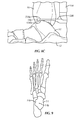
- FIGs. 1A-24 an ankle fusion device, generally designated 10, and various instrumentation for implanting the same.
- Severe arthrosis and deformity of the ankle and subtalar joints may be debilitating problems that can be difficult to treat.
- Tibotalocalcaneal fusion fusion of the calcaneus, talus and tibia
- Ankle arthrodesis may be a challenging procedure due to poor host conditions (e.g., bad skin, deformity, and avascular necrosis), inability to get adequate fixation for this slow healing process, and the inability to get adequate compression across the fusion.
- Performing an ankle arthrodesis can also be technically demanding because of the shape and small size of the talus and calcaneus.
- known methods of installing ankle arthrodeses may limit the optimal configuration of the nail and fixation screws.
- Embodiments of ankle fusion device 10 are configured and shaped to obtain more optimal bony purchase in the calcaneus 12 and talus 14 and/or increase comfort.
- ankle fusion device 10 obtains more optimal bony purchase and/or increase comfort by more accurately approximating the anatomy of the lower limb and using the instrumentation and methods described below to prepare the bones for implanting ankle fusion device 10.
- the embodiments disclosed below and shown in the drawings are for the left ankle. If not otherwise mentioned below, ankle fusion device 10, the instrumentation and methods are mirrored across the sagittal plane of the body for the right ankle.
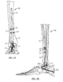
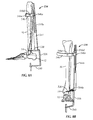
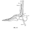
- an exemplary ankle fusion device 10 is shown implanted within the calcaneus 12, talus 14 and tibia 16 of a patient.
- Ankle fusion device 10 includes a nail 18 and a plurality of fasteners 20.
- Fasteners 20 may include any fastening device such as but not limited to pegs, nails, wires, screws, fixation screws, bone screws and locking screws.
- nail 18 is constructed from titanium, stainless steel, alloy, ceramic, and/or other solid biocompatible material.
- nail 18 is substantially rigid.
- at least a portion of an exterior surface of nail 18 is treated to improve biocompatibility and/or osteointegration (e.g., textured, titanium plasma spray coating, hydroxyapatite coating, etc.).
- Nail 18 includes a proximal portion 18a having an axis A 1 generally extending along, or in the direction of, a first longitudinal axis L 1 that corresponds to the general vertical center of tibia 16 (or in other words, proximal portion 18a is generally perpendicular to a transverse plane of the patient).
- Proximal portion 18a includes a proximal end 18b and at least one fastener hole (e.g., fastener hole 222c) for receiving a fastener 20.
- Nail 18 also includes a distal portion 18c extending to a distal end 18d from proximal portion 18a along a second longitudinal axis L 2 co-axially aligned with axis A 2 .
- Second longitudinal axis L 2 is oriented at an oblique angle relative to first longitudinal axis L 1 .
- nail 18 extends laterally and proximally downwardly or ventrally through the calcaneus once implanted.
- nail 18 also arcs anteriorly as it extends upwardly through the tibia 16 such that at least a portion of proximal portion 18a is arcuate. In one embodiment, the entire proximal portion 18a is arcuate. In one embodiment first longitudinal axis L 1 is tangent to the distal most end of axis A 1 of proximal portion 18a. Having an arcuate proximal portion 18a may help in positioning and/or fixing nail 18 within the canal of tibia 16. In one embodiment, proximal portion 18a has an arcuate curve such that proximal end 18b is spaced a distance dp from first longitudinal axis L 1 in a first direction d 1 .
- distance d p is about 36 mm for a 300 mm long nail 18.
- proximal portion 18a has a radius of curvature of about 1.5 m. In one embodiment, the radius of curvature of proximal portion 18a is generally equal to the radius of curvature of an anterior tibial canal surface.
- proximal end 18b is spaced a distance dp from first longitudinal axis L 1 in a first direction d 1 and second longitudinal axis L 2 is oriented at oblique angles in second and third directions d 2 , d 3 relative to first longitudinal axis L 1 .
- second direction d 2 is perpendicular to first direction d 1 and third direction d 3 is opposite first direction d 1 .
- first direction d 1 corresponds to a forward or anterior direction
- second direction d 2 corresponds to an outward or lateral direction
- third direction d 3 corresponds to a rear or posterior direction relative to the ankle.
- proximal portion 18a is substantially straight. In one such embodiment, proximal portion 18a is co-axial with first longitudinal axis L 1 .
- proximal portion 18a extends into tibia 16
- distal portion 18c extends through calcaneus 12
- first direction d 1 is in an anterior direction
- second direction d 2 is in a lateral direction
- third direction d 3 is in a posterior direction.
- proximal end 18b is tapered or pointed, in order to facilitate insertion into the canal of tibia 16.
- proximal end 18b is tapered and configured to prevent a stress concentration on the canal of tibia 16 once nail 18 is implanted that may otherwise be caused by a nail end having a sharp edge.
- proximal end 18b is a blunt or rounded tip.
- proximal end 18b is closed.
- nail 18 has a generally circular cross section throughout its length. In alternative embodiments, nail 18 may have any cross section shape including but not limited to square, star, rectangular and triangular. In one embodiment, nail 18 has a plurality of sections that decrease in diameter toward a proximal end 18b. In some embodiments, nail 18 tapers or decreases in cross sectional size between distal portion 18c and proximal portion 18a. In some embodiments, distal portion 18c has a larger diameter than the largest diameter of proximal portion 18a. In one embodiment, distal portion 18c has a substantially constant diameter. In one embodiment, distal portion 18c has a diameter of about 8 mm to about 18 mm. In one embodiment, distal portion 18c has a diameter of about 13 mm.
- proximal portion 18a includes a smaller diameter section and a larger diameter section.
- the smaller diameter section is about 7 mm to about 11 mm. In one embodiment, the smaller diameter section is about 9 mm. In one embodiment, the larger diameter section is about 10 mm. In one embodiment, the larger diameter section is about 11.5 mm. In one embodiment, the larger diameter section is about 13 mm. In some embodiments, at least a portion of the larger diameter section is hollow. In some embodiments, the smaller diameter section is not hollow. In some embodiments, the smaller diameter section is proximal to the larger diameter section and distal to proximal end 18b. In some embodiments, nail 18 is substantially solid. In some embodiments, nail 18 is hollow or cannulated.
- proximal portion 18a includes a frustoconical section 18h providing a transition between the larger diameter section and the smaller diameter section of the proximal portion 18a.
- frustoconical section 18h is located at or proximate the center of the proximal portion 18a (e.g., about midway along the length of proximal portion 18a).
- the smaller diameter section is shorter than the larger diameter section.
- the smaller diameter section is longer than the larger diameter section.
- the smaller diameter section and the larger diameter section have lengths that are substantially equal.
- nail 18 has a length of about 200 mm to about 300 mm.
- distal portion 18c is configured to be positioned, at least partially, in talus and calcaneus bones 14, 12 of an ankle of the patient. In some embodiments, distal portion 18c is oriented at an oblique angle relative to proximal portion 18a to maximize purchase of distal portion 18c in talus 14 and calcaneus 12 upon implantation of ankle fusion device 10. In some embodiments, distal portion 18c is configured to be positioned in talus 14 and calcaneus 12 so as to generally pass through the center of talus 14 and calcaneus 12. In some embodiments, upon implantation, distal portion 18c is angled posteriorly and/or laterally relative to proximal portion 18a. In some embodiments, upon implantation, distal portion 18c is angled posteriorly and/or laterally relative to a longitudinal axis of the tibia bone.
- second longitudinal axis L 2 is oriented at an oblique angle relative to first longitudinal axis L 1 in third direction d 3 at an angle ⁇ of about 15 degrees as projected on to a coronal or x-y plane as shown in Fig. 2A .
- second longitudinal axis L 2 is oriented at an oblique angle from first longitudinal axis L 1 in second direction d 2 at an angle ⁇ of about 10 degrees as projected on to a sagittal or y-z plane as shown in Fig. 2B .
- angle ⁇ may be about 5 degrees, about 6 degrees, about 7 degrees, about 8 degrees, about 9 degrees, about 10 degrees, about 11 degrees, about 12 degrees, about 13 degrees, about 14 degrees, exactly 15 degrees, about 16 degrees, about 17 degrees, about 18 degrees, about 19 degrees, about 20 degrees, about 21 degrees, about 22 degrees, about 23 degrees, about 24 degrees, about 25 degrees.
- angle ⁇ may be about 1 degree, about 2 degrees, about 3 degrees, about 4 degrees, about 5 degrees, about 6 degrees, about 7 degrees, about 8 degrees, about 9 degrees, exactly 10 degrees, about 11 degrees, about 12 degrees, about 13 degrees, about 14 degrees, about 16 degrees, about 17 degrees, about 18 degrees, about 19 degrees, about 20 degrees.
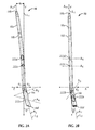
- fastener holes 22 e.g., 222a, 222b, 222c, 222d
- ankle fusion device 10 includes a plurality of through holes or fastener holes 22, at least two of which being positioned at different locations along the length of nail 18, such that one of the at least two fastener holes 22 is positioned on nail 18 proximally or distally relative to the other fastener hole 22.
- the ankle fusion device 10 includes a plurality of fastener holes 22, at least two of which are positioned at different radial locations about first and/or second longitudinal axes L 1 , L 2 of nail 18.
- one or more fastener holes 22 are positioned such that the central axes (see e.g., A 3 -A 6 ) of each fastener hole 22 are substantially perpendicular to first and/or second longitudinal axis L 1 , L 2 of nail 18.
- one or more fastener holes 22 are oriented such that the central axes (e.g., A 3 -A 6 ) through the one or more fastener holes 22 are not perpendicular to first and/or second longitudinal axis L 1 , L 2 of nail 18.
- ankle fusion device 10 includes a plurality of fastener holes 22, at least two of which are differently sized. In some embodiments, ankle fusion device 10 includes a plurality of fastener holes 22, at least two of which are substantially the same size.
- At least some fastener holes 22 may have elongate openings, for example, elongated in a distal-proximal direction such that a fastener 20 positioned in such a fastener hole 22 is capable of shifting proximally or distally within the fastener hole 22.
- at least some of fastener holes 22 e.g, fastener hole 222c may have substantially circular openings.
- a first fastener hole 222a is configured to receive a first fastener 20a for securing nail 18 to calcaneus 12 that is substantially co-axially aligned with a longest dimension of calcaneus 12 as shown.
- first fastener hole 222a is aligned with a central portion of calcaneus 12.
- first fastener hole 222a maybe configured and oriented to have a central axis A 4 substantially co-axially aligned with a central longitudinal axis of calcaneus 12.
- first fastener 222a Co-axial alignment of central axis A 4 with a central portion of the calcaneus bone allows first fastener 222a, in some embodiments, to find greater purchase in calcaneus 12 and to permit a stronger securement thereto.
- the central longitudinal axis of calcaneus 12 generally extends in an anterior direction.
- first fastener 20a has a length substantially matching the length of calcaneus 12 along a central longitudinal axis of calcaneus 12. In some embodiments, first fastener 20a is about 70 mm to about 100 mm.
- a second fastener hole 222b is configured to receive a second fastener 20b for securing nail 18 to talus 14 that is substantially co-axially aligned with a longest dimension of talus 14 as shown.
- second fastener hole 222b may be configured (e.g., angled) to have a central axis A 3 substantially co-axially aligned with a central longitudinal axis of talus 14.
- the central longitudinal axis of talus 14 generally extends in an anterior direction.
- the central longitudinal axis of talus 14 generally extends in an anterior-medial direction.
- second fastener 20b Co-axial alignment of the second fastener hole 222b with a central portion of the talus bone allows the second fastener 20b, in some embodiments, to find greater purchase in the talus 14 and to permit a stronger securement thereto.
- the central longitudinal axis of talus 14 generally extends in an anterior-lateral direction.
- second fastener 20b has a length substantially matching the length of talus 14 along a central longitudinal axis of the talus 14. In some embodiments, second fastener 20b is about 46 mm to about 80 mm.
- the central axes of the first and second elongate fastener holes 222a, 222b are divergent (e.g., as they extend anteriorly), such that the central axes are not parallel and/or not coplanar.
- the first elongate fastener hole 222a may have a different (e.g., larger) dimension than the second elongate fastener hole 222b, for example, so as to accept larger fasteners and/or permit greater shifting of the fastener.
- first fastener hole 222a is elongated such that first fastener 20a can be translated proximally with respect to second longitudinal axis L 2 while being parallel with axis A 4 .
- axis A 4 is about 25 degrees to about 35 degrees relative to second longitudinal axis L 2 .
- axis A 4 is about 30 degrees relative to second longitudinal axis L 2 .
- second fastener hole 222b is elongated such that second fastener 20b can be translated with respect to second longitudinal axis L 2 while being parallel with axis A 3 .
- axis A 3 is about 85 degrees to about 95 degrees relative to second longitudinal axis L 2 . In one embodiment, axis A 3 is generally perpendicular to second longitudinal axis L 2 . In alternative embodiments, first and second fastener holes 222a, 222b are not elongated such that the respective fastener 20a, 20b generally cannot translate relative to nail 18.
- Proximal portion 18a includes at least one fastener hole 22.
- proximal portion 18a of nail 18 includes a locking or static fastener hole 222c.
- the locking fastener hole 222c is configured to receive a third fastener 20c and sized to substantially prevent translational movement of third fastener 20c relative to nail 18.
- proximal portion 18a of nail 18 includes a dynamic fastener hole 222d.
- dynamic fastener hole 222d is elongated such that nail 18 can be translated proximally with respect to a fourth fastener 20d extending through dynamic fastener hole 222d.
- fourth fastener 20d is installed toward the proximal end of dynamic fastener hole 222d such that nail 18 is substantially prevented from moving distally with respect to tibia 16 but allows for a predetermined amount of proximal movement to allow for, for example, additional compression of the ankle joint.
- third fastener 20c and fourth fastener 20d may be used depending on whether it is desired to fix nail 18 relative to tibia 16.
- dynamic fastener hole 222d has an axis A 5 such that fourth fastener 20d can be translated distally with respect to first longitudinal axis L 1 while being parallel with axis A 5 .
- axis A 5 is substantially perpendicular to first longitudinal axis L 1 in the coronal or x-y plane as shown in Fig. 2B .
- locking fastener hole 222c has an axis A 6 that is substantially aligned with third fastener 20c.
- axis A 6 is substantially perpendicular to first longitudinal axis L 1 in the coronal or x-y plane as shown in Fig. 2B .
- axes A 5 and A 6 are substantially parallel to one another.
- axes A 5 and A 6 may be oriented at oblique angles with respect to first longitudinal axis L 1 and/or each other.
- nail 18 may include a compression mechanism to move two or more of calcaneus 12, talus 14 and tibia 16 closer together.
- nail 18 includes a bore 18e extending proximally from distal end 18d along second longitudinal axis L 2 .
- bore 18e is at least partially threaded.
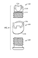
- Ankle fusion device 10 may include a compression screw 324.
- compression screw 324 is configured to be received in bore 18e and translate therein along second longitudinal axis L 2 .
- compression screw 324 includes an engagement portion 324a having a concave surface configured to contact first fastener 20a when first fastener 20a is received in first fastener hole 222a.
- engagement portion 324a includes a projection 324b extending into a groove 18f in the bore 18e to prevent the engagement portion 324a from rotating about the second longitudinal axis L 2 as the engagement portion 324a translates proximally up bore 18e.
- bore 18e includes a projection that is received in a corresponding groove in engagement portion 324a.
- the compression screw 324 includes a threaded portion 324c attachable to engagement portion 324a.
- Threaded portion 324c includes threads configured to engage the threads of bore 18e.
- threaded portion 324c is rotatably attached to engagement portion 324a.
- threaded portion 324c includes an engagement member 324d such as, for example a hexagon socket or slot, for mating with a screw driver tool 326. As threaded portion 324c is rotated, compression screw 324 advances proximally through bore 18e and translates first fastener 20c proximally (e.g., across first fastener hole 222a).
- first fastener 20a is fixed relative to calcaneus 12 and at least one of third and fourth fasteners 20c, 20d keep nail 18 from being pulled distally, advancing compression screw 324 moves calcaneus 12 proximally toward talus 14.
- second fastener hole 222b is elongate, advancing compression screw 324 proximally moves talus 14 toward tibia 16.
- both first and second fastener holes 222a, 222b are elongate, advancing compression screw 324 proximally moves both calcaneus and talus toward tibia 16 and compresses all three bones together.
- bore 18e extends entirely through distal portion 18c.
- bore 18e extends substantially through the entire nail 18 such that nail 18 is generally hollow. In some embodiments, bore 18e extends at least partially through distal portion 18c. In an alternative embodiment, bore 18e extends only through distal portion 18c that is distal to first fastener hole 222a.
- ankle fusion device 10 includes, in one embodiment, an end cap screw 428 for closing bore 18e after implantation and compression.
- end cap screw 428 is threaded for engagement of the threads in bore 18e.
- end cap screw 428 is not threaded and instead snap fits into bore 18e.
- distal end 18d of nail 18 includes a groove or step 18g for engaging and orienting tools about and relative to second longitudinal axis L 2 as described in further detail below.
- ankle fusion device 10 may include an end cap sleeve 430.
- End cap sleeve 430 includes one or more projections 430a on a proximal end that are configured to align with groove 18g and an end surface 430b on a distal end that forms the distal most end of ankle fusion device 10.
- end surface 430b is configured to be substantially flush with the surrounding calcaneus 12 and with the end cap screw 428, proximate the end of bore 18e.
- a path is created, e.g., by advancing (e.g., drilling) a hole proximally starting from the bottom of calcaneus 12.
- one or more guidewires are inserted through the calcaneus 12, talus 14 and tibia 16 to fix reference axes for forming a path for nail 18.
- a guidewire targeting device 534 is used in implanting ankle fusion device 10.
- the guidewire targeting device 534 may eliminate the need for less accurate freehand guidewire insertion techniques that are typically used to install an ankle arthrodesis.
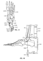
- Guidewire targeting device 534 may use the orientation of the patient's anatomy (e.g., tibia 16, talus 14 and/or foot) to position at least one cutting apparatus (e.g., guidewire 1060) up through calcaneus 12, talus 14 and tibia 16 (see Fig. 10 ).
- guidewire targeting device 534 is configured to account for the posterolateral bend of nail 18 as described above and sets the proper orientation for the drilling and placement of nail 18.
- guidewire targeting device 534 includes a frame 536 for at least partially surrounding the calcaneus 12 and talus 14.
- frame 536 includes a target arm 538 having a guidewire target 538a configured and dimensioned to be inserted between talus 12 and tibia 16 proximate a talar dome 14a (see Figs. 8c and 9 ) of talus 14.
- first sleeve arm 540 is positioned distally from calcaneus 12 when the guidewire target 538a is inserted between talus 14 and tibia 16 proximate talar dome 14a.
- guidewire target 538a is a semi-circular indentation in the distal end of target arm 538.
- guidewire target 538a includes a marker that is visible using an imaging device such as but not limited to a radio-marker that is visible using an imaging device and/or a guide such as a slot, a hole or a projection.
- target arm 538 includes one or more downwardly extending projections 538b used to aid in aligning guidewire target 538a with a center or apex 14b of talar dome 14a.
- projections 538b include a pair of projections 538b positioned on either side of guidewire target 538a.
- the distal end of target arm 538 is thinner than the remainder of the frame 536 such that target arm 538 fits more easily between talus 14 and tibia 16 while maintaining the strength of the remainder of frame 536.
- frame 536 includes a first sleeve arm 540.
- first sleeve arm 540 includes a proximal side facing towards target arm 538 and a distal side opposite the proximal side.
- frame 536 is substantially C-shaped.
- frame 536 is bent or at least arcuate such that target arm 538 extends above talar dome 14a while first sleeve arm 540 extends under calcaneus 12.
- target arm 538 and first sleeve arm 540 are substantially parallel.
- first sleeve arm 540 includes a first guidewire sleeve 542.
- first guidewire sleeve 542 is integral with first sleeve arm 540.
- first guidewire sleeve 542 is detachable from first sleeve arm 540.
- first guidewire sleeve 542 is positioned at or proximate a free end of first sleeve arm 540. In one example, at least a portion of first guidewire sleeve 542 extends from the proximal side of first sleeve arm 540.
- first guidewire sleeve 542 may extend from the distal side of first sleeve arm 540. In one example, first guidewire sleeve 542 extends from the proximal side and the distal side of first sleeve arm 540. In one embodiment, first guidewire sleeve 542 is fixed in position relative to guidewire target 538a. In one embodiment, a central longitudinal axis of first guidewire sleeve 542 is configured to co-axially align with first guidewire axis A 7 . In another example, first guidewire sleeve 542 is fixed in position relative to target arm 538. Also first guidewire sleeve 542 may be radially disposed about first guidewire axis A 7 or first guidewire axis A 7 is aligned with guidewire target 538a.
- guidewire targeting device 534 may be aligned with and/or attached to at least one anatomical feature of the patient.
- the at least one anatomical feature is tibia 16.
- guidewire targeting device 534 includes a tibial member or alignment guide 544.
- tibial alignment guide 544 is engaged with frame 536 and is configured to extend proximally therefrom along a longitudinal axis substantially parallel to the first guidewire axis A 7 .
- tibial alignment guide 544 is attached to target arm 538.
- tibial alignment guide 544 is moveably attached to frame 536 using a fastener 544b.
- tibial alignment guide 544 is moveably attached to frame 536 using a star grind fastener such that tibial alignment guide 544 may be positioned relative to tibia 16 and frame 536 may be independently rotated about first longitudinal axis L 1 and then locked in position relative to tibial alignment guide 544 once in the appropriate position.
- the position of frame 536 relative to tibial alignment guide 544 is adjustable but generally set by the surgeon prior to attaching to the patient.
- the position of frame 536 relative to tibial alignment guide 544 is adjustable once guidewire targeting device 534 has been attached to the patient, or the position of frame 536 relative to tibial alignment guide 544 is radially adjustable.
- transverse member 546 is fixed to frame 536.
- tibial alignment guide 544 may include a transverse member 546.
- Transverse member 546 may extend generally perpendicularly from tibial alignment guide 544.
- transverse member 546 is configured to have a curvature about first guidewire axis A 7 , such that the transverse member 546 wraps at least partially around the leg during use.
- the transverse member 546 is positionable at different locations along a length of tibial alignment guide 544 to aid in aligning first guide wire axis A 7 with first longitudinal axis L 1 during use as described further below.
- tibial alignment guide 544 includes a longitudinal slot 544a extending at least partially along a length of tibial alignment guide 544.
- transverse member 546 includes a fastener 546a such as a screw knob that extends through longitudinal slot 544a.
- transverse member 546 may be movable attached to or fixedly attached but moveable relative to tibial alignment guide 544 in any manner.
- tibial alignment guide 544 instead of a longitudinal slot 544a, tibial alignment guide 544 includes a plurality of holes.
- transverse member 546 is fixed relative to or integral with tibial alignment guide 544.
- transverse member 546 is bendable or conformable such that the surgeon can shape transverse member 546 to the shape of the patient's leg.
- transverse member 546 includes an attachment member (not shown) such as, for example, a Velcro strap and/or elastic band that is configured to attached to the patient's leg.
- frame 536 and/or transverse member 546 may be attached to tibial alignment guide 544 in the opposite facing direction for use with the right ankle.
- frame 536 and/or tibial alignment guide 544 includes indicia (not shown) to indicate the proper orientation of or connection between components of guidewire targeting device 534 for the left and right foot.
- frame 536 and/or transverse member 546 includes indicia (not shown) to indicate the general position frame 536 should be oriented to tibial alignment guide 544 depending on the position of the patient during surgery.
- transverse member 545 includes indicia 546b, 546c to indicate the proper orientation for the left and right foot.
- transverse member 546 is shaped for use when the patient is in the supine position. In some examples, a differently shaped transverse member 546 may be provided for patients in the prone position. In alternative examples, a single transverse member 546 is provided and frame 536 may be attached to tibial alignment guide 544 in a radial orientation relative to tibial alignment guide 544 depending on the position of the patient.
- Transverse member 546 may include a first alignment member 546d for aligning with the first longitudinal axis L 1 and/or first guidewire 1060 as described further below.
- Transverse member 546 may include a second alignment member 546e for aligning with first longitudinal axis L 1 and/or first guidewire 1060.
- first and/or second alignment members 546d, 546e are configured and positioned to intersect with a plane aligned with the first guidewire axis A 7 .
- first and second alignment members 546d, 546e include indents or bends in the transverse member 546, or first and second alignment members 546d, 546e include one or more projections and/or grooves in the transverse member 546, or first and second alignment members 546d, 546e include a marker that is visible using an imaging device such as but not limited to a radio-marker that is visible using an imaging device.
- the horizontal thickness of first and second alignment members 546d, 546e is generally equal to a thickness of first guidewire 1060.
- first alignment member 546d is positioned along the length of transverse member 546 such that first alignment member 546d aligns with first longitudinal axis L 1 from a lateral view of tibia 16 and second alignment member 546e is positioned along the length of transverse member 546e such that second alignment member 546e aligns with first longitudinal axis L 1 from an anterior view of tibia 16. Also aligning first and second alignment member 546e with first longitudinal axis L 1 from two directions helps to ensure that tibial alignment guide 534 is substantially parallel with first longitudinal axis L l .
- guidewire targeting device 534 may include a second guidewire template 648 for use with a second guidewire 1262.
- Second guidewire template 648 is configured to align a second guidewire axis A 8 with the guidewire target 538a.
- Second guidewire template 648 includes a second position sleeve 648a radially disposed about a second guidewire axis A 8 .
- first guidewire sleeve 542 is used to co-axially align first guidewire axis A 7 with first longitudinal axis L 1 and second position sleeve 648a is used to co-axially align second guidewire axis A 8 with the desired position of second longitudinal axis L 2 .
- guidewire targeting device 534 is configured to position second longitudinal axis L 1 .
- guidewire targeting device 534 is configured to align first longitudinal axis L 1 with the central longitudinal axis of tibia 16 and guidewire targeting device 534 is configured to position second longitudinal axis L 2 in a preselected orientation with respect to the position of first longitudinal axis L 1 .
- the preselected orientation is based on the shape of nail 18.
- Second guidewire template 648 may be integral, moveable and/or detachable with frame 536.
- second guidewire template 648 is removably attached to first sleeve arm 540
- second guidewire template 648 is positioned distally with respect to frame 536.
- second guidewire template 648 is configured to abut the distal side of first sleeve arm 540.
- second guidewire template 648 is positioned such that at least a portion of first sleeve arm 540 is located between second guidewire template 648 and target arm 538.
- second guidewire template 648 is positioned between target arm 538 and first sleeve arm 540.
- second guidewire template 648 includes an attachment sleeve 648c.
- attachment sleeve 648c is configured and dimensioned to engage with at least a portion of first guidewire sleeve 542.
- attachment sleeve 648c is configured to engage with a portion of first guidewire sleeve 542 that extends from the distal side of first sleeve arm 540.
- attachment sleeve 648c is compression fit over first guidewire sleeve 542 such that attachment sleeve 648c is moveable with respect to first guidewire sleeve 542 but remains in place relative to first guidewire sleeve 542 after first guidewire sleeve 542 is positioned and released by the surgeon.
- attachment sleeve 648c snap fits onto first guidewire sleeve 542 such that movement of attachment sleeve 648c is retained along first guidewire axis A 7 but is free to rotate about first guidewire axis A 7 .
- second position sleeve 648a is configured to rotate about first guidewire axis A 7 .
- second position sleeve 648a is translatable along an arc about first guidewire axis A 7 .
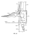
- Second position sleeve 648a is configured to be a retainer for receiving and aligning a second guidewire sleeve 1252 (see, e.g., Fig. 12 ) along second guidewire axis A 8 .
- second guidewire sleeve 1252 is integral with second position sleeve 648a.
- Second guidewire template 648 may include an alignment arm 648b for positioning second guidewire axis A 8 relative to first longitudinal axis L 1 by aligning alignment arm 648b relative to an anatomical feature of the patient.
- alignment arm 648b may be used to position second guidewire axis A 8 relative to first guidewire axis A 7 and relative to first longitudinal axis L 1 by aligning alignment arm 648b relative to an anatomical feature of the patient.
- second guidewire template 648 is configured such that second guidewire axis A 8 is substantially aligned with guidewire target 538a and/or center 14b of talar dome 14a when alignment arm 648b is aligned with a pre-selected anatomical feature of the patient.
- alignment arm 648b extends generally perpendicularly from first guidewire axis A 7 .
- the pre-selected anatomical feature aligned with the alignment arm 648b is generally perpendicular to the central axis of tibia 16 (i.e., first longitudinal axis L 1 ).
- the pre-selected anatomical feature is a second metatarsal bone 1150 (see Fig. 11 ).
- alignment arm 648b is aligned to be substantially parallel with second metatarsal 1150 to determine the position of second guidewire axis A 8 .
- the pre-selected anatomical feature is any one of the elongated bones in the foot.
- first and second guidewires 1060, 1262 may be used to properly align nail 18 with the patient's anatomy.
- first guidewire 1060 is generally aligned with first longitudinal axis L 1 (e.g., the central longitudinal axis of tibia 16) and second guidewire 1262 is generally aligned with the position of second longitudinal axis L 2 once nail 18 is implanted (e.g., at an oblique angle relative to first longitudinal axis L 1 ).
- first and second guidewires 1060, 1262 are used in order to form a cutting path corresponding to the bent shape of nail 18 using two generally straight lines.
- a single guidewire may be used if the guidewire bends during insertion or if the foot is positioned such that the paths for the first and second longitudinal axes L 1 , L 2 are co-axially aligned during insertion of the guidewire.
- first and second guidewires 1060, 1262 allows for more accurate alignment with first and second longitudinal axes L 1 , L 2 since first guidewire 1060 is used to co-axially align with first longitudinal axis L 1 using anatomical features such as the talar dome 14a and the tibia 16 and the second wire 1262 can be positioned relative to the first guidewire 1062 (or the path created by the first guidewire).
- the position of the patient may be determined based on the type of arthrodesis procedure performed and the discretion of the surgeon.
- the patient is placed in the prone position.
- the patient is placed in the supine position.
- guidewire targeting device 534 is placed in the posterior (not shown) or posterolateral position (the position shown in Figs. 8A-12 ). Where a patient is in the supine position, the guidewire targeting device 534 may be placed in the anterolateral position.
- the foot may be oriented relative to tibia 16 in the position that the ankle is to be fixed in place.
- the ankle is placed in a neutral position. Or, the ankle is placed in about 2 to about 3 degrees dorsi flexion.
- guidewire target 538a is inserted between talus 14 and tibia 16.
- Guidewire target 538a is placed proximate talar dome 14a (see Fig. 9 ).
- guidewire target 538a is placed proximate center 14b of talar dome 14a.
- guidewire target 538a is positioned generally directly above center 14b of talar dome 14a.
- center 14b of talar dome 14a is aligned with first longitudinal axis L 1 and the central axis of tibia 16. Also, projections 538b are positioned on either side of center 14b of talar dome 14a. The position of guidewire target 538a relative to talus 14 is viewed using imaging such as fluoroscopic imaging.
- first guidewire sleeve 542 is positioned under calcaneus such that first guidewire axis A 7 generally aligns with guidewire target 538a.
- First guidewire sleeve 542 is positioned so that first guidewire sleeve 542 aligns exactly with guidewire target 538a.
- first guidewire sleeve 542 is positioned so that first guidewire axis A 7 is aligned with center 14b of talar dome 14a.
- tibial alignment guide 544 is used to help align the first guidewire axis A 7 with first longitudinal axis L 1 by positioning tibial alignment guide 544 substantially parallel with tibia 16.
- first alignment member 546d and/or second alignment member 546e are aligned with first longitudinal axis L 1 in the lateral and anterior views, respectively, to position tibial alignment guide 544 substantially parallel with tibia 16.
- tibial alignment guide 544 is positioned relative to first longitudinal axis L 1 by sliding or otherwise positioning transverse member 546 along the length of tibial alignment guide 544 and in contact with the outer surface of the leg.
- transverse member 546 prevents guidewire targeting device 534 from moving with respect to the patient.
- guidewire targeting device 534 would pivot laterally and posteriorly relative to guidewire target 538a caused by the weight of guidewire targeting device 534.
- transverse member 546 counters any pivot of guidewire targeting device 534 with respect to the guidewire target 538a.
- moving transverse member 546 along the length of tibial alignment guide 544 alters the orientation of first guidewire axis A 7 in a first plane until first guidewire axis A 7 is aligned with first longitudinal axis L 1 Also, the curvature of transverse member 546 keeps first guidewire axis A 7 aligned with first longitudinal axis L 1 in a second plane, the second plane being generally perpendicular to the first plane.
- first guidewire 1060 is advanced proximally through first guidewire sleeve 542, along first guide wire axis A 7 , through calcaneus 12 and talus 14 and into the distal end of tibia 16.
- the placement and guidance of first guidewire 1060 is monitored using the imaging device.
- the guidance of first guidewire 1060 is monitored using the imaging device from lateral and mortise views.
- first guidewire 1060 is aligned with first alignment member 546d and/or second alignment member 546e in the lateral and anterior views, respectively.
- Advancement of the first guidewire 1060 along first guidewire axis A 7 creates a channel in the distal end of tibia 16 substantially aligned with first longitudinal axis L 1 .
- second guidewire template 648 is attached to guidewire targeting device 534.
- second guidewire template 648 include indicia 648d (see Fig. 6 ) such as the word "Left" and/or color coding to indicate the appropriate left or right foot.
- second guidewire template 648 may be positioned relative to frame 536 and/or first guidewire axis A 7 by aligning alignment arm 648b with an anatomical feature of the patient such as second metatarsal 1150.
- second guidewire axis A 8 generally aligns with guidewire target 538a and is co-axial with where second longitudinal axis L 2 will be.
- second guidewire axis Ag generally aligns with the anterior margin of the plantar aspect of the calcaneal tuberosity equidistant from the medial and lateral wall of calcaneus 12.
- second guidewire sleeve 1252 is inserted into second position sleeve 648a if second guidewire sleeve 1252 is not already attached. Also second guidewire 1262 is advanced proximally through second guidewire sleeve 1252, through calcaneus 12 and talus 14 proximate the guidewire target 538a. The position of second guidewire 1060 during insertion is monitored using the imaging device from lateral and mortise views.
- first guidewire 1062 and guidewire targeting device 534 are removed such that only second guidewire 1262 remains.
- a cannulated drill 1356 is inserted over the second guidewire 1262.
- the guidewire targeting device 534 is left in place, the second guidewire 1262 is removed and a drill is guided along second guidewire axis A 8 .
- the foot is positioned such that second guidewire 1262 aligns with first longitudinal axis L 1 .
- the foot is positioned such that second guidewire 1262 is substantially aligned with a longitudinal axis of tibia 16.
- Positioning the foot includes angling the foot relative to tibia 16 such that second guidewire 1262 is substantially aligned with the channel created in the distal end of tibia 16 by the first guidewire 1060.
- second guidewire 1262 is then advanced into the channel created in the distal end of tibia 16 by the first guidewire 1060.
- a protection sleeve 1458 is inserted over second guidewire 1262 to aid in positioning the foot and protects the cannulated drill 1356.
- the foot is dorsiflexed about 15 degrees and inverted 10 degrees. Once the foot has been repositioned, cannulated drill 1356 is advanced into tibia 16 over second guidewire 1262.
- reamers 1564 is inserted through the path created by the cannulated drill 1356.
- a narrow tibial canal may hinder insertion of nail 18.
- Progressive reaming of the tibial canal is performed using reamers having cross sectional widths of about 0.5 mm to about 1 mm larger than the diameter of nail 18.
- nail 18 may be inserted proximally through calcaneus 12 and talus 14 and into tibia 16.
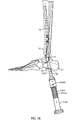
- An insertion handle 1666 is attached to distal end 18d of nail 18 to aid in insertion of nail 18.
- Insertion handle 1666 is configured to align with the at least one groove 18g in nail 18 so that the radial position of insertion handle 1666 is fixed relative to distal portion 18c of nail 18.
- insertion handle 1666 is coupled to distal portion 18c of nail 18 using a threaded connecting screw (not shown) that extends upwardly into bore 18e of nail 18.
- nail 18 is inserted as far as possible by gripping the insertion handle and pushing nail 18 upwardly across the ankle joint.
- a driving cap 1668 may be coupled to insertion handle 1666.
- driving cap 1668 includes a distal end surface to which a force may be applied to facilitate insertion of nail 18. Once nail 18 has been inserted, in one embodiment, nail 18 is rotated into its final position using the driving cap 1668 and insertion handle 1666. Also placement of nail 18 is guided and monitored using the imaging device.
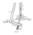
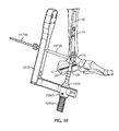
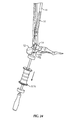
- an aiming arm 1870 is attached to insertion handle 1666.
- the aiming arm 1870 may be used to insert some or all of fasteners 22 relative to the position of nail 18.
- insertion handle 1666 includes one or more longitudinally extending alignment features 1666a such a groove or projection.
- Alignment feature 1666a includes a plurality of grooves spaced circumferentially around insertion handle 1666.
- insertion handle 1666 includes a plurality of indicia 1666b spaced radially around the insertion handle 1666. Indicia 666b are used to indicate the position of aiming arm 1870 relative to first and second longitudinal axes L 1 , L 2 .
- indicia 1666b includes markings such as letters that correspond to respective fasteners 20. For example, when aiming arm 1870 is aligned with first fastener hole 22a, indicia 1666b may show "C” through a viewing window in aiming arm 1870 to indicate that the hole marked "Calcaneus Screw” for calcaneus 12 should be used with the appropriate drill 1874a, drill sleeve 1872a and screw 20a.
- first fastener 20a is inserted into the most distal end of first fastener hole 22a.
- second fastener 20b is inserted into the most distal end of second fastener hole 22b.
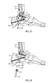
- third fastener 20c in one embodiment, there are three options 1) static locking, 2) dynamic locking and 3) originally static with the option to later make dynamic.
- third fastener 20c is inserted into third fastener hole 20c to prevent nail 18 from moving relative to tibia 16.
- fourth fastener 20d is inserted into the most proximal end of fourth fastener hole 22d.
- fourth fastener 20d is inserted into the most proximal end of fourth fastener hole 22d and third fastener 20c is inserted into third fastener hole 20c.
- Such an embodiment prevents nail 18 from moving relative to tibia 18 until third fastener 20c is removed at which point nail 18 may move proximally up tibia 16 if calcaneus 12 and/or talus 14 are compressed further toward tibia 16 (e.g., if bone graft compresses).
- compression screw 324 may be driven proximally through bore 18e using a screw driver 326.
- compression screw 324 engages first fastener 22a. Since calcaneus 12 is fixed relative to first fastener 22a and nail 18 is prevented from moving distal due third and/or fourth fasteners 22c, 22d, the calcaneus is shifted proximally toward tibia 16.
- calcaneus 12 engages talus 14 in embodiments with an elongated second fastener hole 22b, both calcaneus 12 and talus 14 are shifted proximally toward tibia 16.
- end cap sleeve 430 and end cap screw 428 may be inserted into distal end 18d of nail 18 to seal bore 183.
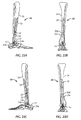
- Figs. 23A-23D illustrate an exemplary ankle fusion device 10 after installation.
- ankle fusion device 10 is left implanted in the patient until calcaneus 12, talus 14 and/or tibia 16 are sufficiently fused together.
- an extraction tool 2576 maybe used to assist in distracting nail 18 from the patient.
- extraction tool 2576 is threadably attached to distal end 18d of nail 18.
- extraction tool 2576 is pulled and/or hammered distally to remove nail 18.
- kits for performing the ankle arthrodeses described herein may include one or more of each of the instruments, fasteners and/or implantable devices described herein.
- a kit for performing ankle arthrodesis includes nail 18, one or more fasteners 20, guidewire targeting device 534, and at least one guidewire 1060.
- a kit for performing ankle arthrodesis includes nail 18, one or more fasteners 20, guidewire targeting device 534, first guidewire 1060 and second guidewire 1062.
- a kit for performing ankle arthrodesis includes guidewire targeting device 534, and at least one guidewire 1060.
- a kit for performing ankle arthrodesis includes guidewire targeting device 534, at least one guidewire 1060, and aiming arm 1870.
Landscapes
- Health & Medical Sciences (AREA)
- Life Sciences & Earth Sciences (AREA)
- Surgery (AREA)
- Orthopedic Medicine & Surgery (AREA)
- Medical Informatics (AREA)
- General Health & Medical Sciences (AREA)
- Biomedical Technology (AREA)
- Heart & Thoracic Surgery (AREA)
- Nuclear Medicine, Radiotherapy & Molecular Imaging (AREA)
- Molecular Biology (AREA)
- Animal Behavior & Ethology (AREA)
- Engineering & Computer Science (AREA)
- Public Health (AREA)
- Veterinary Medicine (AREA)
- Dentistry (AREA)
- Oral & Maxillofacial Surgery (AREA)
- Neurology (AREA)
- Surgical Instruments (AREA)
- Prostheses (AREA)
Description
- The present invention, includes an implantable device, for fusing ankle bones of a mammalian patient. More particularly, the invention is directed to an arthrodesis nail.
- International application
WO2007/120539 discloses an embodiment of an arthrodesis nail provided for ankle fusion. - According to the invention, is proposed an intramedullary nail for ankle fusion as described in the appended claims.
- In one embodiment there is an intramedullary nail for ankle fusion that includes a proximal portion generally extending along a first longitudinal axis. The proximal portion includes a proximal end and a first fastener hole. The proximal portion has an arcuate curve such that the proximal end is spaced a distance from the first longitudinal axis in a first direction. The first fastener hole is configured to receive a first fastener along a first fastener axis. A distal portion of the intramedullary nail extends to a distal end from the proximal portion along a second longitudinal axis. The second longitudinal axis is angled in second and third directions relative to the first longitudinal axis. The second direction is perpendicular to the first direction and the third direction is opposite the first direction. The distal portion includes a second fastener hole configured to receive a second fastener along a second fastener axis. In one embodiment, the second fastener hole is elongate and the distal portion further includes a bore extending proximally from the distal end along the second longitudinal axis. The bore is at least partially threaded. The distal portion further includes an elongate third fastener hole configured to receive a third fastener along a third fastener axis.
- In a further embodiment, the intramedullary nail comprises a compression screw configured to be received in the bore and translate therein along the second longitudinal axis. In one embodiment, the compression screw includes an engagement portion having a concave surface configured to contact the third fastener when the third fastener is received in the third fastener hole and a threaded portion attachable to the engagement portion and having external threads configured comprising a proximal portion extending along a longitudinal axis and including a proximal end and a distal portion extending parallel to the proximal portion to a distal end and including a fastener hole, and two bends between the proximal and distal portion. to engage the threads of the bore. In one embodiment, the bore does not extend through the entire distal portion.
- In a further embodiment, the intramedullary nail further comprises an end cap set screw having a closed distal end and external screws configured to engage the threads of the bore. In one embodiment, the distal portion includes a third fastener hole configured to receive a third fastener along a third fastener axis. In one embodiment, the second fastener axis is oriented at an oblique angle relative to the third fastener axis. In one embodiment, the second fastener axis and the third fastener axis lie on planes that are parallel to one another. In one embodiment, the third fastener axis is configured to be substantially aligned with a longest dimension of a talus once the ankle fusion device is implanted. In one embodiment, the proximal portion further comprises a fourth fastener hole configured to receive a fourth fastener along a fourth fastener axis. In one embodiment, the fourth fastener axis and the first fastener axis are substantially parallel. In one embodiment, the fourth fastener hole is elongate.
- In one embodiment, the distal end includes a truncated surface that is generally perpendicular to the first longitudinal axis and oriented at an oblique angle relative to the second longitudinal axis. In one embodiment, the second fastener axis is configured to be substantially aligned with a longest dimension of a calcaneus bone once the ankle fusion device is implanted. In one embodiment, once the intramedullary nail is implanted in a body the proximal portion extends into a tibia, the distal portion extends through a calcaneus, the first direction is in an anterior direction, the second direction is in a lateral direction and the third direction is in a posterior direction. In one embodiment, the entire proximal portion is arcuate in the first direction. In one embodiment, the proximal portion is least partially cannulated. In one embodiment, the proximal portion is substantially solid.
- In this document is also described a device for positioning at least one guidewire in a calcaneus bone and talus bone comprises a frame configured and dimensioned to at least partially surround the calcaneus bone and the talus bone. The frame includes a guidewire target configured and dimensioned to be inserted between the talus bone and a tibia bone proximate a talar dome of the talus bone and a first guidewire sleeve radially disposed about a first guidewire axis. The first guidewire axis is aligned with the guidewire target.
- In a further example the device includes a second guidewire template attached to the frame and having a second guidewire sleeve radially disposed about a second guidewire axis. In one embodiment, the second guidewire template includes an alignment guide extending therefrom. In one embodiment, the second guidewire axis extends towards the guidewire target when the alignment guide is substantially aligned with a pre-selected anatomical feature. In one embodiment, the pre-selected anatomical feature is a second metatarsal bone. In one embodiment, the second guidewire axis is positioned at an oblique angle relative to the first guidewire axis when the alignment guide is substantially aligned with the pre-selected anatomical feature. In on embodiment, the second guidewire template is configured to rotate about the first guidewire axis. In one embodiment, the second guidewire template is slideable and rotatable relative to the first guidewire sleeve.
- In a further example the device includes a tibial alignment guide engaged with the frame and configured to extend proximally therefrom along a longitudinal axis substantially parallel to the first guidewire axis. In one embodiment, the tibial alignment guide includes a transverse member being positionable at a location along a longitudinal axis of the tibial alignment guide. In one embodiment, the transverse member has a curvature about the first guidewire axis. In one embodiment, the frame further comprises a targeting arm that includes the guidewire target and the tibial member is attachable to the targeting arm. In one embodiment, an extension of the tibial alignment guide includes at least one alignment member, the at least one alignment member configured and positioned to intersect with a plane aligned with the first guidewire axis. In one embodiment, the tibial alignment guide is rotatably attachable with the frame.
- In one example the frame further comprises a targeting arm that includes the guidewire target, the targeting arm and the first sleeve arm being substantially parallel to one another. In one embodiment, the first sleeve is fixed in position relative to the targeting arm. In one embodiment, the first guidewire axis is configured to substantially align with a center of the talar dome and to the guidewire target when the guidewire target is inserted between the talus and the tibia proximate the talar dome. In one embodiment, the first sleeve arm is positioned distally from the calcaneus bone when the guidewire target is inserted between the talus bone and the tibia bone proximate the talar dome of the talus bone.
- In this document is also described a method for positioning a guidewire in a calcaneus bone, talus bone, and tibia bone, includes: inserting a guidewire target on a guidewire targeting device into an ankle joint at a distal end of the tibia bone such that the guidewire target is proximate a talar dome of the talus bone; positioning a first guidewire sleeve on the guidewire targeting device proximate the calcaneus bone, the first guidewire sleeve pointing toward the guidewire target to provide a first guidewire axis; aligning the first guidewire axis of the first guidewire sleeve generally co-axially with a longitudinal axis of the tibia bone; and advancing a first guidewire along the first guidewire axis through the first guidewire sleeve and into the distal tibia bone through the calcaneus bone and talar dome of the talus bone.
- This method includes: positioning a second guidewire axis of a guidewire template coupled to the guidewire targeting device at an oblique angle relative to the first guidewire axis; aligning the second guidewire axis with the talar dome of the talus bone and; and advancing a second guidewire along the second guidewire axis through a second guidewire sleeve on the guidewire temple and into the calcaneus bone and the talar bone until an end of the second guidewire generally reaches the first guidewire.
- In one example the second guidewire axis includes rotating the guidewire template relative to the guidewire targeting device until an alignment arm of the guidewire template is substantially aligned with an anatomical feature. In one embodiment, the anatomical feature is a long axis of a second metatarsal bone. In one embodiment, the guidewire template is rotatably coupled to the guidewire targeting device. In one embodiment, the guidewire temple is slideably coupled over a portion of the first guidewire sleeve surrounding the first guidewire axis.
- In a further example the method includes: removing the first guidewire; advancing a cannulated resection device over the second guidewire and through the calcaneus and the talus; performing a dorsiflexion and inversion of the ankle joint to align the second guidewire with the longitudinal axis of the tibia bone; advancing the second guidewire into the tibia bone along the longitudinal axis of the tibia bone; and further advancing the cannulated resection device over the second guidewire and into the tibia.
- In one example the second guidewire axis is angled laterally and posteriorly relative to the first guidewire axis. In a further embodiment, the method comprises: positioning an elongate member coupled with the guidewire targeting device substantially parallel to the longitudinal axis of the tibia bone. In one example a proximal arm extends from the guidewire target and a distal arm extends from the first guidewire sleeve, the proximal arm being generally parallel to and spaced from the distal arm. In one example aligning the first guidewire axis includes aligning the guidewire target with a center of the talar dome.
- In a further example the method includes bracing an alignment guide of the guidewire targeting device against an anterior surface of an outside of a leg. In one example aligning the first guidewire axis of the first guidewire sleeve generally co-axially with the longitudinal axis of the tibia bone includes positioning an alignment member of the guidewire targeting device proximal the tibia bone on a plane aligned with the longitudinal axis of the tibia bone.
- The foregoing summary, as well as the following detailed description of embodiments of the Ankle Fusion Device, will be better understood when read in conjunction with the appended drawings of an exemplary embodiment. It should be understood, however, that the invention is not limited to the precise arrangements and instrumentalities shown.
- In the drawings:
-
Fig. 1A is a posterior elevational view of an ankle fusion device including a nail in accordance with an exemplary embodiment of the present invention shown implanted in a semitransparent skeleton; -
Fig. 1B is a lateral elevational view of the nail shown inFig. 1A ; -
Fig. 2A is a lateral elevational view of the nail ofFig. 1A ; -
Fig. 2B is an anterior elevational view of the nail ofFig. 1A ; -
Fig. 3 is a partial perspective view of a distal portion of the nail ofFig. 1A illustrating the use of a compression screw in accordance with an exemplary embodiment of the present invention; -
Fig. 4 is an exploded perspective view of the compression screw ofFig. 3 and end caps for use with the ankle fusion device ofFig. 1A ; -
Fig. 5 is a posterior perspective view of a guidewire targeting device; -
Fig. 6 is a ventral or bottom plan view of a guidewire template; -
Fig. 7 is a perspective view of the guidewire targeting device ofFig. 5 in use with a guidewire template ofFig. 6 showing first and second guidewire axes; -
Fig. 8A is a lateral elevational view of the guidewire targeting device ofFig. 5 in use upon initial insertion; -
Fig. 8B is an anterior elevational view of the guidewire targeting device shown inFig. 8A ; -
Fig. 8C is an enlarged lateral elevational view of the guidewire targeting device shown inFig. 8A ; -
Fig. 9 is a dorsal or top plan view of a target on the talar dome of the talus; -
Fig. 10 is a lateral elevational view of the guidewire targeting device shown inFig. 8A in use with a first guidewire; -
Fig. 11 is a ventral or bottom plan view of the guidewire targeting device and guidewire template ofFig. 7 in use with the first and second guidewires; -
Fig. 12 is a lateral elevational view of the guidewire targeting device and guidewire template shown inFig. 11 ; -
Fig. 13 is a lateral elevational view of a cannulated drill being used with the second guidewire; -
Fig. 14 is a lateral elevational view of the second guidewire and cannulated drill ofFig. 13 and a protection sleeve -
Fig. 15 is a lateral elevational view of a reamer ; -
Fig. 16 is a lateral elevational view of a nail being inserted using an insertion handle ; -
Fig. 17 is a medial elevational view of a calcaneus screw being inserted using an aiming arm; -
Fig. 18 is a medial elevational view of a talar screw being inserted using an aiming arm; -
Fig. 19 is a posterior elevational view of a first tibial screw being inserted using an aiming arm; -
Fig. 20 is an anterior elevational view of a second tibial screw being inserted using an aiming arm; -
Fig. 21 is a medial elevational view of a compression system of the ankle fusion device ofFig. 1 ; -
Fig. 22 is a medial elevational view of end cap sleeve and end cap screw ofFig. 4 being inserted in the ankle fusion device ofFig. 1A ; -
Fig. 23A is a medial elevational view of the implanted ankle fusion device ofFig. 1A ; -
Fig. 23B is a lateral elevational view of the implanted ankle fusion device ofFig. 1A ; -
Fig. 23C is an anterior elevational view of the implanted ankle fusion device ofFig. 1A ; -
Fig. 23D is a posterior elevational view of the implanted ankle fusion device ofFig. 1A ; and -
Fig. 24 is a medial elevational view of the implanted nail ofFig. 1A attached to an extraction tool. - Referring to the drawings in detail, wherein like reference numerals indicate like elements throughout, there is shown in
Figs. 1A-24 an ankle fusion device, generally designated 10, and various instrumentation for implanting the same. - Severe arthrosis and deformity of the ankle and subtalar joints may be debilitating problems that can be difficult to treat. Tibotalocalcaneal fusion (fusion of the calcaneus, talus and tibia) with an intramedullary nail can be considered a salvage procedure for severe arthrosis and deformity of the ankle and subtalar joints. Ankle arthrodesis may be a challenging procedure due to poor host conditions (e.g., bad skin, deformity, and avascular necrosis), inability to get adequate fixation for this slow healing process, and the inability to get adequate compression across the fusion. Performing an ankle arthrodesis can also be technically demanding because of the shape and small size of the talus and calcaneus. Furthermore, known methods of installing ankle arthrodeses may limit the optimal configuration of the nail and fixation screws.
- Embodiments of
ankle fusion device 10 are configured and shaped to obtain more optimal bony purchase in thecalcaneus 12 andtalus 14 and/or increase comfort. In some embodiments,ankle fusion device 10 obtains more optimal bony purchase and/or increase comfort by more accurately approximating the anatomy of the lower limb and using the instrumentation and methods described below to prepare the bones for implantingankle fusion device 10. The embodiments disclosed below and shown in the drawings are for the left ankle. If not otherwise mentioned below,ankle fusion device 10, the instrumentation and methods are mirrored across the sagittal plane of the body for the right ankle. - Referring to
Figs. 1A and 1B , an exemplaryankle fusion device 10 is shown implanted within thecalcaneus 12,talus 14 andtibia 16 of a patient.Ankle fusion device 10 includes anail 18 and a plurality offasteners 20.Fasteners 20 may include any fastening device such as but not limited to pegs, nails, wires, screws, fixation screws, bone screws and locking screws. In some embodiments,nail 18 is constructed from titanium, stainless steel, alloy, ceramic, and/or other solid biocompatible material. In some embodiments,nail 18 is substantially rigid. In some embodiments, at least a portion of an exterior surface ofnail 18 is treated to improve biocompatibility and/or osteointegration (e.g., textured, titanium plasma spray coating, hydroxyapatite coating, etc.). - Referring to
Figs. 2A and 2B , an exemplary embodiment ofnail 18 for the left ankle is shown.Nail 18 includes aproximal portion 18a having an axis A1 generally extending along, or in the direction of, a first longitudinal axis L1 that corresponds to the general vertical center of tibia 16 (or in other words,proximal portion 18a is generally perpendicular to a transverse plane of the patient).Proximal portion 18a includes aproximal end 18b and at least one fastener hole (e.g.,fastener hole 222c) for receiving afastener 20.Nail 18 also includes adistal portion 18c extending to adistal end 18d fromproximal portion 18a along a second longitudinal axis L2 co-axially aligned with axis A2. Second longitudinal axis L2 is oriented at an oblique angle relative to first longitudinal axis L1. In one embodiment,nail 18 extends laterally and proximally downwardly or ventrally through the calcaneus once implanted. - In one embodiment, nail 18 also arcs anteriorly as it extends upwardly through the
tibia 16 such that at least a portion ofproximal portion 18a is arcuate. In one embodiment, the entireproximal portion 18a is arcuate. In one embodiment first longitudinal axis L1 is tangent to the distal most end of axis A1 ofproximal portion 18a. Having an arcuateproximal portion 18a may help in positioning and/or fixingnail 18 within the canal oftibia 16. In one embodiment,proximal portion 18a has an arcuate curve such thatproximal end 18b is spaced a distance dp from first longitudinal axis L1 in a first direction d1. In one embodiment, distance dp is about 36 mm for a 300 mmlong nail 18. In one embodiment,proximal portion 18a has a radius of curvature of about 1.5 m. In one embodiment, the radius of curvature ofproximal portion 18a is generally equal to the radius of curvature of an anterior tibial canal surface. - In one embodiment,
proximal end 18b is spaced a distance dp from first longitudinal axis L1 in a first direction d1 and second longitudinal axis L2 is oriented at oblique angles in second and third directions d2, d3 relative to first longitudinal axis L1. In one embodiment, second direction d2 is perpendicular to first direction d1 and third direction d3 is opposite first direction d1. In one embodiment, oncenail 18 is implanted, first direction d1 corresponds to a forward or anterior direction, second direction d2 corresponds to an outward or lateral direction and third direction d3 corresponds to a rear or posterior direction relative to the ankle. In an alternative embodiment,proximal portion 18a is substantially straight. In one such embodiment,proximal portion 18a is co-axial with first longitudinal axis L1. - In one embodiment, once
ankle fusion device 10 is implanted in a body,proximal portion 18a extends intotibia 16,distal portion 18c extends throughcalcaneus 12, first direction d1 is in an anterior direction, second direction d2 is in a lateral direction and third direction d3 is in a posterior direction. In some embodiments,proximal end 18b is tapered or pointed, in order to facilitate insertion into the canal oftibia 16. In some embodiment,proximal end 18b is tapered and configured to prevent a stress concentration on the canal oftibia 16 oncenail 18 is implanted that may otherwise be caused by a nail end having a sharp edge. In one embodiment,proximal end 18b is a blunt or rounded tip. In one embodiment,proximal end 18b is closed. - In one embodiment,
nail 18 has a generally circular cross section throughout its length. In alternative embodiments,nail 18 may have any cross section shape including but not limited to square, star, rectangular and triangular. In one embodiment,nail 18 has a plurality of sections that decrease in diameter toward aproximal end 18b. In some embodiments, nail 18 tapers or decreases in cross sectional size betweendistal portion 18c andproximal portion 18a. In some embodiments,distal portion 18c has a larger diameter than the largest diameter ofproximal portion 18a. In one embodiment,distal portion 18c has a substantially constant diameter. In one embodiment,distal portion 18c has a diameter of about 8 mm to about 18 mm. In one embodiment,distal portion 18c has a diameter of about 13 mm. - In some embodiments,
proximal portion 18a includes a smaller diameter section and a larger diameter section. In one embodiment, the smaller diameter section is about 7 mm to about 11 mm. In one embodiment, the smaller diameter section is about 9 mm. In one embodiment, the larger diameter section is about 10 mm. In one embodiment, the larger diameter section is about 11.5 mm. In one embodiment, the larger diameter section is about 13 mm. In some embodiments, at least a portion of the larger diameter section is hollow. In some embodiments, the smaller diameter section is not hollow. In some embodiments, the smaller diameter section is proximal to the larger diameter section and distal toproximal end 18b. In some embodiments,nail 18 is substantially solid. In some embodiments,nail 18 is hollow or cannulated. - In some embodiments,
proximal portion 18a includes afrustoconical section 18h providing a transition between the larger diameter section and the smaller diameter section of theproximal portion 18a. In some embodiments,frustoconical section 18h is located at or proximate the center of theproximal portion 18a (e.g., about midway along the length ofproximal portion 18a). In some embodiments, the smaller diameter section is shorter than the larger diameter section. In other embodiments, the smaller diameter section is longer than the larger diameter section. in some embodiments, the smaller diameter section and the larger diameter section have lengths that are substantially equal. In some embodiments,nail 18 has a length of about 200 mm to about 300 mm. - In some embodiments,
distal portion 18c is configured to be positioned, at least partially, in talus andcalcaneus bones distal portion 18c is oriented at an oblique angle relative toproximal portion 18a to maximize purchase ofdistal portion 18c intalus 14 andcalcaneus 12 upon implantation ofankle fusion device 10. In some embodiments,distal portion 18c is configured to be positioned intalus 14 andcalcaneus 12 so as to generally pass through the center oftalus 14 andcalcaneus 12. In some embodiments, upon implantation,distal portion 18c is angled posteriorly and/or laterally relative toproximal portion 18a. In some embodiments, upon implantation,distal portion 18c is angled posteriorly and/or laterally relative to a longitudinal axis of the tibia bone. - In the exemplary embodiment shown in
Figs. 2A and 2B , second longitudinal axis L2 is oriented at an oblique angle relative to first longitudinal axis L1 in third direction d3 at an angle α of about 15 degrees as projected on to a coronal or x-y plane as shown inFig. 2A . In the exemplary embodiment shown, second longitudinal axis L2 is oriented at an oblique angle from first longitudinal axis L1 in second direction d2 at an angle β of about 10 degrees as projected on to a sagittal or y-z plane as shown inFig. 2B . In an example for the embodiment shown, ifnail 18 were removed, inverting theleft foot 10 degrees and dorsiflexing the foot 15 degrees would co-axially align second longitudinal axis L2 and first longitudinal axis L1. In other embodiments, angle α may be about 5 degrees, about 6 degrees, about 7 degrees, about 8 degrees, about 9 degrees, about 10 degrees, about 11 degrees, about 12 degrees, about 13 degrees, about 14 degrees, exactly 15 degrees, about 16 degrees, about 17 degrees, about 18 degrees, about 19 degrees, about 20 degrees, about 21 degrees, about 22 degrees, about 23 degrees, about 24 degrees, about 25 degrees. In other embodiments, angle β may be about 1 degree, about 2 degrees, about 3 degrees, about 4 degrees, about 5 degrees, about 6 degrees, about 7 degrees, about 8 degrees, about 9 degrees, exactly 10 degrees, about 11 degrees, about 12 degrees, about 13 degrees, about 14 degrees, about 16 degrees, about 17 degrees, about 18 degrees, about 19 degrees, about 20 degrees. - Referring to
Figs. 1A and 1B , fastener holes 22 (e.g., 222a, 222b, 222c, 222d) extending throughnail 18 are spaced along the length ofnail 18 and are configured to receivefasteners 20. In some embodiments,ankle fusion device 10 includes a plurality of through holes or fastener holes 22, at least two of which being positioned at different locations along the length ofnail 18, such that one of the at least twofastener holes 22 is positioned onnail 18 proximally or distally relative to theother fastener hole 22. In some embodiments, theankle fusion device 10 includes a plurality of fastener holes 22, at least two of which are positioned at different radial locations about first and/or second longitudinal axes L1, L2 ofnail 18. In some embodiments, one or more fastener holes 22 are positioned such that the central axes (see e.g., A3-A6) of eachfastener hole 22 are substantially perpendicular to first and/or second longitudinal axis L1, L2 ofnail 18. In some embodiments, one or more fastener holes 22 are oriented such that the central axes (e.g., A3-A6) through the one or more fastener holes 22 are not perpendicular to first and/or second longitudinal axis L1, L2 ofnail 18. In some embodiments,ankle fusion device 10 includes a plurality of fastener holes 22, at least two of which are differently sized. In some embodiments,ankle fusion device 10 includes a plurality of fastener holes 22, at least two of which are substantially the same size. In some embodiments, at least some fastener holes 22 may have elongate openings, for example, elongated in a distal-proximal direction such that afastener 20 positioned in such afastener hole 22 is capable of shifting proximally or distally within thefastener hole 22. In some embodiments, at least some of fastener holes 22 (e.g,fastener hole 222c may have substantially circular openings. - In one embodiment, a
first fastener hole 222a is configured to receive afirst fastener 20a for securingnail 18 to calcaneus 12 that is substantially co-axially aligned with a longest dimension ofcalcaneus 12 as shown. In one embodiment,first fastener hole 222a is aligned with a central portion ofcalcaneus 12. For example,first fastener hole 222a maybe configured and oriented to have a central axis A4 substantially co-axially aligned with a central longitudinal axis ofcalcaneus 12. Co-axial alignment of central axis A4 with a central portion of the calcaneus bone allowsfirst fastener 222a, in some embodiments, to find greater purchase incalcaneus 12 and to permit a stronger securement thereto. In one embodiment, the central longitudinal axis ofcalcaneus 12 generally extends in an anterior direction. In some embodiments,first fastener 20a has a length substantially matching the length ofcalcaneus 12 along a central longitudinal axis ofcalcaneus 12. In some embodiments,first fastener 20a is about 70 mm to about 100 mm. - In one embodiment, a
second fastener hole 222b is configured to receive asecond fastener 20b for securingnail 18 totalus 14 that is substantially co-axially aligned with a longest dimension oftalus 14 as shown. For example,second fastener hole 222b may be configured (e.g., angled) to have a central axis A3 substantially co-axially aligned with a central longitudinal axis oftalus 14. In one embodiment, the central longitudinal axis oftalus 14 generally extends in an anterior direction. In one embodiment, the central longitudinal axis oftalus 14 generally extends in an anterior-medial direction. Co-axial alignment of thesecond fastener hole 222b with a central portion of the talus bone allows thesecond fastener 20b, in some embodiments, to find greater purchase in thetalus 14 and to permit a stronger securement thereto. In one embodiment, the central longitudinal axis oftalus 14 generally extends in an anterior-lateral direction. In some embodiments,second fastener 20b has a length substantially matching the length oftalus 14 along a central longitudinal axis of thetalus 14. In some embodiments,second fastener 20b is about 46 mm to about 80 mm. - Preferably, the central axes of the first and second
elongate fastener holes elongate fastener hole 222a may have a different (e.g., larger) dimension than the secondelongate fastener hole 222b, for example, so as to accept larger fasteners and/or permit greater shifting of the fastener. - Referring to
Figs. 2A and 2B , in one embodiment,first fastener hole 222a is elongated such thatfirst fastener 20a can be translated proximally with respect to second longitudinal axis L2 while being parallel with axis A4. In one embodiment, axis A4 is about 25 degrees to about 35 degrees relative to second longitudinal axis L2. In one embodiment, axis A4 is about 30 degrees relative to second longitudinal axis L2. In one embodiment,second fastener hole 222b is elongated such thatsecond fastener 20b can be translated with respect to second longitudinal axis L2 while being parallel with axis A3. In one embodiment, axis A3 is about 85 degrees to about 95 degrees relative to second longitudinal axis L2. In one embodiment, axis A3 is generally perpendicular to second longitudinal axis L2. In alternative embodiments, first andsecond fastener holes respective fastener -
Proximal portion 18a includes at least onefastener hole 22. In one embodiment,proximal portion 18a ofnail 18 includes a locking orstatic fastener hole 222c. In such an embodiment, the lockingfastener hole 222c is configured to receive athird fastener 20c and sized to substantially prevent translational movement ofthird fastener 20c relative to nail 18. In one embodiment,proximal portion 18a ofnail 18 includes adynamic fastener hole 222d. In one embodiment,dynamic fastener hole 222d is elongated such thatnail 18 can be translated proximally with respect to afourth fastener 20d extending throughdynamic fastener hole 222d. In such an embodiment and as described in further detail below,fourth fastener 20d is installed toward the proximal end ofdynamic fastener hole 222d such thatnail 18 is substantially prevented from moving distally with respect totibia 16 but allows for a predetermined amount of proximal movement to allow for, for example, additional compression of the ankle joint. Either one of or boththird fastener 20c andfourth fastener 20d may be used depending on whether it is desired to fixnail 18 relative totibia 16. - In one embodiment,
dynamic fastener hole 222d has an axis A5 such thatfourth fastener 20d can be translated distally with respect to first longitudinal axis L1 while being parallel with axis A5. In one embodiment, axis A5 is substantially perpendicular to first longitudinal axis L1 in the coronal or x-y plane as shown inFig. 2B . In one embodiment, lockingfastener hole 222c has an axis A6 that is substantially aligned withthird fastener 20c. In one embodiment, axis A6 is substantially perpendicular to first longitudinal axis L1 in the coronal or x-y plane as shown inFig. 2B . In one embodiment, axes A5 and A6 are substantially parallel to one another. In alternative embodiments, axes A5 and A6 may be oriented at oblique angles with respect to first longitudinal axis L1 and/or each other. - Referring to
Figs. 3 and4 , in embodiments withelongated fasteners holes 222a and/or 222b,nail 18 may include a compression mechanism to move two or more ofcalcaneus 12,talus 14 andtibia 16 closer together. To facilitate compression, in one embodiment,nail 18 includes abore 18e extending proximally fromdistal end 18d along second longitudinal axis L2. In one embodiment, bore 18e is at least partially threaded.Ankle fusion device 10 may include acompression screw 324. In one embodiment,compression screw 324 is configured to be received inbore 18e and translate therein along second longitudinal axis L2. In one embodiment,compression screw 324 includes anengagement portion 324a having a concave surface configured to contactfirst fastener 20a whenfirst fastener 20a is received infirst fastener hole 222a. In one embodiment,engagement portion 324a includes aprojection 324b extending into agroove 18f in thebore 18e to prevent theengagement portion 324a from rotating about the second longitudinal axis L2 as theengagement portion 324a translates proximally upbore 18e. In an alternative embodiment, bore 18e includes a projection that is received in a corresponding groove inengagement portion 324a. - The
compression screw 324 includes a threadedportion 324c attachable toengagement portion 324a. Threadedportion 324c includes threads configured to engage the threads ofbore 18e. In one embodiment, threadedportion 324c is rotatably attached toengagement portion 324a. In one embodiment, threadedportion 324c includes anengagement member 324d such as, for example a hexagon socket or slot, for mating with ascrew driver tool 326. As threadedportion 324c is rotated,compression screw 324 advances proximally throughbore 18e and translatesfirst fastener 20c proximally (e.g., acrossfirst fastener hole 222a). Sincefirst fastener 20a is fixed relative to calcaneus 12 and at least one of third andfourth fasteners nail 18 from being pulled distally, advancingcompression screw 324 moves calcaneus 12 proximally towardtalus 14. Similarly, ifsecond fastener hole 222b is elongate, advancingcompression screw 324 proximally movestalus 14 towardtibia 16. If both first andsecond fastener holes compression screw 324 proximally moves both calcaneus and talus towardtibia 16 and compresses all three bones together. In one embodiment, bore 18e extends entirely throughdistal portion 18c. In one embodiment, bore 18e extends substantially through theentire nail 18 such thatnail 18 is generally hollow. In some embodiments, bore 18e extends at least partially throughdistal portion 18c. In an alternative embodiment, bore 18e extends only throughdistal portion 18c that is distal tofirst fastener hole 222a. - Referring to
Figs. 3 and4 ,ankle fusion device 10, includes, in one embodiment, anend cap screw 428 for closingbore 18e after implantation and compression. In one embodiment,end cap screw 428 is threaded for engagement of the threads inbore 18e. In an alternative embodiment,end cap screw 428 is not threaded and instead snap fits intobore 18e. - In some embodiments,
distal end 18d ofnail 18 includes a groove orstep 18g for engaging and orienting tools about and relative to second longitudinal axis L2 as described in further detail below. In such embodiments,ankle fusion device 10 may include anend cap sleeve 430.End cap sleeve 430 includes one ormore projections 430a on a proximal end that are configured to align withgroove 18g and anend surface 430b on a distal end that forms the distal most end ofankle fusion device 10. In one embodiment,end surface 430b is configured to be substantially flush with the surroundingcalcaneus 12 and with theend cap screw 428, proximate the end ofbore 18e. - In some embodiments, in order to insert
nail 18 into thecalcaneus 12,talus 14 andtibia 16, a path is created, e.g., by advancing (e.g., drilling) a hole proximally starting from the bottom ofcalcaneus 12. Referring toFigs. 5-12 , in some embodiments, one or more guidewires are inserted through thecalcaneus 12,talus 14 andtibia 16 to fix reference axes for forming a path fornail 18. - Referring to
Fig. 5 , in some embodiments, aguidewire targeting device 534 is used in implantingankle fusion device 10. Theguidewire targeting device 534 may eliminate the need for less accurate freehand guidewire insertion techniques that are typically used to install an ankle arthrodesis.Guidewire targeting device 534 may use the orientation of the patient's anatomy (e.g.,tibia 16,talus 14 and/or foot) to position at least one cutting apparatus (e.g., guidewire 1060) up throughcalcaneus 12,talus 14 and tibia 16 (seeFig. 10 ). In one embodiment,guidewire targeting device 534 is configured to account for the posterolateral bend ofnail 18 as described above and sets the proper orientation for the drilling and placement ofnail 18. - In one example
guidewire targeting device 534 includes aframe 536 for at least partially surrounding thecalcaneus 12 andtalus 14. In oneexample frame 536 includes atarget arm 538 having aguidewire target 538a configured and dimensioned to be inserted betweentalus 12 andtibia 16 proximate atalar dome 14a (seeFigs. 8c and 9 ) oftalus 14. In one examplefirst sleeve arm 540 is positioned distally fromcalcaneus 12 when theguidewire target 538a is inserted betweentalus 14 andtibia 16proximate talar dome 14a. In one embodiment,guidewire target 538a is a semi-circular indentation in the distal end oftarget arm 538. In other examples,guidewire target 538a includes a marker that is visible using an imaging device such as but not limited to a radio-marker that is visible using an imaging device and/or a guide such as a slot, a hole or a projection. In one example,target arm 538 includes one or more downwardly extendingprojections 538b used to aid in aligningguidewire target 538a with a center or apex 14b oftalar dome 14a. In one example,projections 538b include a pair ofprojections 538b positioned on either side ofguidewire target 538a. In one embodiment, the distal end oftarget arm 538 is thinner than the remainder of theframe 536 such thattarget arm 538 fits more easily betweentalus 14 andtibia 16 while maintaining the strength of the remainder offrame 536. - In order to align a first guidewire axis A7 with the
guidewire target 538a, in one embodiment,frame 536 includes afirst sleeve arm 540. In one example,first sleeve arm 540 includes a proximal side facing towardstarget arm 538 and a distal side opposite the proximal side. In one embodiment,frame 536 is substantially C-shaped. In one example,frame 536 is bent or at least arcuate such thattarget arm 538 extends abovetalar dome 14a whilefirst sleeve arm 540 extends undercalcaneus 12. In another example,target arm 538 andfirst sleeve arm 540 are substantially parallel. In one example,first sleeve arm 540 includes afirst guidewire sleeve 542. In one embodiment,first guidewire sleeve 542 is integral withfirst sleeve arm 540. In one embodiment,first guidewire sleeve 542 is detachable fromfirst sleeve arm 540. In one embodiment,first guidewire sleeve 542 is positioned at or proximate a free end offirst sleeve arm 540. In one example, at least a portion offirst guidewire sleeve 542 extends from the proximal side offirst sleeve arm 540. At least a portion offirst guidewire sleeve 542 may extend from the distal side offirst sleeve arm 540. In one example,first guidewire sleeve 542 extends from the proximal side and the distal side offirst sleeve arm 540. In one embodiment,first guidewire sleeve 542 is fixed in position relative toguidewire target 538a. In one embodiment, a central longitudinal axis offirst guidewire sleeve 542 is configured to co-axially align with first guidewire axis A7. In another example,first guidewire sleeve 542 is fixed in position relative to targetarm 538. Alsofirst guidewire sleeve 542 may be radially disposed about first guidewire axis A7 or first guidewire axis A7 is aligned withguidewire target 538a. - In order to co-axially align first guidewire axis A7 with first longitudinal axis L1, guidewire targeting
device 534 may be aligned with and/or attached to at least one anatomical feature of the patient. In one embodiment, the at least one anatomical feature istibia 16. In one example,guidewire targeting device 534 includes a tibial member oralignment guide 544. In one embodiment,tibial alignment guide 544 is engaged withframe 536 and is configured to extend proximally therefrom along a longitudinal axis substantially parallel to the first guidewire axis A7. In one embodiment,tibial alignment guide 544 is attached to targetarm 538. In another example,tibial alignment guide 544 is moveably attached to frame 536 using afastener 544b. In one example,tibial alignment guide 544 is moveably attached to frame 536 using a star grind fastener such thattibial alignment guide 544 may be positioned relative totibia 16 andframe 536 may be independently rotated about first longitudinal axis L1 and then locked in position relative totibial alignment guide 544 once in the appropriate position. Also the position offrame 536 relative totibial alignment guide 544 is adjustable but generally set by the surgeon prior to attaching to the patient. In one example, the position offrame 536 relative totibial alignment guide 544 is adjustable once guidewire targetingdevice 534 has been attached to the patient, or the position offrame 536 relative totibial alignment guide 544 is radially adjustable. In other examples,transverse member 546 is fixed to frame 536. - To further aid in positioning
guidewire targeting device 534,tibial alignment guide 544 may include atransverse member 546.Transverse member 546 may extend generally perpendicularly fromtibial alignment guide 544. Ortransverse member 546 is configured to have a curvature about first guidewire axis A7, such that thetransverse member 546 wraps at least partially around the leg during use. In one embodiment, thetransverse member 546 is positionable at different locations along a length oftibial alignment guide 544 to aid in aligning first guide wire axis A7 with first longitudinal axis L1 during use as described further below. In one embodiment,tibial alignment guide 544 includes alongitudinal slot 544a extending at least partially along a length oftibial alignment guide 544. Ortransverse member 546 includes afastener 546a such as a screw knob that extends throughlongitudinal slot 544a. In alternative embodiments,transverse member 546 may be movable attached to or fixedly attached but moveable relative totibial alignment guide 544 in any manner. Or, instead of alongitudinal slot 544a,tibial alignment guide 544 includes a plurality of holes. Ortransverse member 546 is fixed relative to or integral withtibial alignment guide 544. - Or
transverse member 546 is bendable or conformable such that the surgeon can shapetransverse member 546 to the shape of the patient's leg. In one example,transverse member 546 includes an attachment member (not shown) such as, for example, a Velcro strap and/or elastic band that is configured to attached to the patient's leg. In another example,frame 536 and/ortransverse member 546 may be attached totibial alignment guide 544 in the opposite facing direction for use with the right ankle. - In one example,
frame 536 and/ortibial alignment guide 544 includes indicia (not shown) to indicate the proper orientation of or connection between components ofguidewire targeting device 534 for the left and right foot. In one example,frame 536 and/ortransverse member 546 includes indicia (not shown) to indicate thegeneral position frame 536 should be oriented totibial alignment guide 544 depending on the position of the patient during surgery. In one example, transverse member 545 includesindicia transverse member 546 is shaped for use when the patient is in the supine position. In some examples, a differently shapedtransverse member 546 may be provided for patients in the prone position. In alternative examples, a singletransverse member 546 is provided andframe 536 may be attached totibial alignment guide 544 in a radial orientation relative totibial alignment guide 544 depending on the position of the patient. -
Transverse member 546 may include afirst alignment member 546d for aligning with the first longitudinal axis L1 and/orfirst guidewire 1060 as described further below.Transverse member 546 may include asecond alignment member 546e for aligning with first longitudinal axis L1 and/orfirst guidewire 1060. In one embodiment, first and/orsecond alignment members second alignment members transverse member 546, or first andsecond alignment members transverse member 546, or first andsecond alignment members second alignment members first guidewire 1060. In one example,first alignment member 546d is positioned along the length oftransverse member 546 such thatfirst alignment member 546d aligns with first longitudinal axis L1 from a lateral view oftibia 16 andsecond alignment member 546e is positioned along the length oftransverse member 546e such thatsecond alignment member 546e aligns with first longitudinal axis L1 from an anterior view oftibia 16. Also aligning first andsecond alignment member 546e with first longitudinal axis L1 from two directions helps to ensure thattibial alignment guide 534 is substantially parallel with first longitudinal axis Ll. - Referring to
Figs. 6 and 7 ,guidewire targeting device 534 may include asecond guidewire template 648 for use with asecond guidewire 1262.Second guidewire template 648 is configured to align a second guidewire axis A8 with theguidewire target 538a.Second guidewire template 648 includes asecond position sleeve 648a radially disposed about a second guidewire axis A8. In one example,first guidewire sleeve 542 is used to co-axially align first guidewire axis A7 with first longitudinal axis L1 andsecond position sleeve 648a is used to co-axially align second guidewire axis A8 with the desired position of second longitudinal axis L2. Also, guidewire targetingdevice 534 is configured to position second longitudinal axis L1. In one exampleguidewire targeting device 534 is configured to align first longitudinal axis L1 with the central longitudinal axis oftibia 16 andguidewire targeting device 534 is configured to position second longitudinal axis L2 in a preselected orientation with respect to the position of first longitudinal axis L1. The preselected orientation is based on the shape ofnail 18. - Second guidewire template 648 (see, e.g.,
Fig., 6 ) may be integral, moveable and/or detachable withframe 536. In one example,second guidewire template 648 is removably attached tofirst sleeve arm 540 Or,second guidewire template 648 is positioned distally with respect toframe 536. In one examplesecond guidewire template 648 is configured to abut the distal side offirst sleeve arm 540. Or,second guidewire template 648 is positioned such that at least a portion offirst sleeve arm 540 is located betweensecond guidewire template 648 andtarget arm 538. In other examples, at least a portion ofsecond guidewire template 648 is positioned betweentarget arm 538 andfirst sleeve arm 540. In one embodiment,second guidewire template 648 includes anattachment sleeve 648c. In one embodiment,attachment sleeve 648c is configured and dimensioned to engage with at least a portion offirst guidewire sleeve 542. In one example,attachment sleeve 648c is configured to engage with a portion offirst guidewire sleeve 542 that extends from the distal side offirst sleeve arm 540. Or,attachment sleeve 648c is compression fit overfirst guidewire sleeve 542 such thatattachment sleeve 648c is moveable with respect tofirst guidewire sleeve 542 but remains in place relative tofirst guidewire sleeve 542 afterfirst guidewire sleeve 542 is positioned and released by the surgeon. Or,attachment sleeve 648c snap fits ontofirst guidewire sleeve 542 such that movement ofattachment sleeve 648c is retained along first guidewire axis A7 but is free to rotate about first guidewire axis A7. In one example,second position sleeve 648a is configured to rotate about first guidewire axis A7. Or,second position sleeve 648a is translatable along an arc about first guidewire axis A7. -
Second position sleeve 648a is configured to be a retainer for receiving and aligning a second guidewire sleeve 1252 (see, e.g.,Fig. 12 ) along second guidewire axis A8. Or,second guidewire sleeve 1252 is integral withsecond position sleeve 648a. -
Second guidewire template 648 may include analignment arm 648b for positioning second guidewire axis A8 relative to first longitudinal axis L1 by aligningalignment arm 648b relative to an anatomical feature of the patient. In examples, wheresecond guidewire template 648 is moveable with respect to frame 536,alignment arm 648b may be used to position second guidewire axis A8 relative to first guidewire axis A7 and relative to first longitudinal axis L1 by aligningalignment arm 648b relative to an anatomical feature of the patient. In one example,second guidewire template 648 is configured such that second guidewire axis A8 is substantially aligned withguidewire target 538a and/or center 14b oftalar dome 14a whenalignment arm 648b is aligned with a pre-selected anatomical feature of the patient. Or,alignment arm 648b extends generally perpendicularly from first guidewire axis A7. In one embodiment, the pre-selected anatomical feature aligned with thealignment arm 648b is generally perpendicular to the central axis of tibia 16 (i.e., first longitudinal axis L1). Or, the pre-selected anatomical feature is a second metatarsal bone 1150 (seeFig. 11 ). In one example,alignment arm 648b is aligned to be substantially parallel withsecond metatarsal 1150 to determine the position of second guidewire axis A8. In alternative examples, the pre-selected anatomical feature is any one of the elongated bones in the foot. - Referring to
Figs. 8A-8B ,guidewire targeting device 534 is used to prepare the ankle for insertion ofankle fusion device 10. First andsecond guidewires nail 18 with the patient's anatomy. In one example,first guidewire 1060 is generally aligned with first longitudinal axis L1 (e.g., the central longitudinal axis of tibia 16) andsecond guidewire 1262 is generally aligned with the position of second longitudinal axis L2 oncenail 18 is implanted (e.g., at an oblique angle relative to first longitudinal axis L1). Alternatively, first andsecond guidewires nail 18 using two generally straight lines. Or, a single guidewire may be used if the guidewire bends during insertion or if the foot is positioned such that the paths for the first and second longitudinal axes L1, L2 are co-axially aligned during insertion of the guidewire. In one example, the use of first andsecond guidewires first guidewire 1060 is used to co-axially align with first longitudinal axis L1 using anatomical features such as thetalar dome 14a and thetibia 16 and thesecond wire 1262 can be positioned relative to the first guidewire 1062 (or the path created by the first guidewire). - Before beginning the procedure, the position of the patient may be determined based on the type of arthrodesis procedure performed and the discretion of the surgeon. In one example, the patient is placed in the prone position. In another example, the patient is placed in the supine position. With a patient in the prone position, guidewire targeting
device 534 is placed in the posterior (not shown) or posterolateral position (the position shown inFigs. 8A-12 ). Where a patient is in the supine position, theguidewire targeting device 534 may be placed in the anterolateral position. - Referring to
Figs. 8A-8C and9 , the foot may be oriented relative totibia 16 in the position that the ankle is to be fixed in place. The ankle is placed in a neutral position. Or, the ankle is placed in about 2 to about 3 degrees dorsi flexion. Once the ankle is in the desired position,guidewire target 538a is inserted betweentalus 14 andtibia 16.Guidewire target 538a is placedproximate talar dome 14a (seeFig. 9 ). Or,guidewire target 538a is placed proximate center 14b oftalar dome 14a. In one example,guidewire target 538a is positioned generally directly above center 14b oftalar dome 14a. In one example, center 14b oftalar dome 14a is aligned with first longitudinal axis L1 and the central axis oftibia 16. Also,projections 538b are positioned on either side of center 14b oftalar dome 14a. The position ofguidewire target 538a relative totalus 14 is viewed using imaging such as fluoroscopic imaging. - In addition to
positioning guidewire target 538a relative totalus 14,first guidewire sleeve 542 is positioned under calcaneus such that first guidewire axis A7 generally aligns withguidewire target 538a. Firstguidewire sleeve 542 is positioned so thatfirst guidewire sleeve 542 aligns exactly withguidewire target 538a. Or,first guidewire sleeve 542 is positioned so that first guidewire axis A7 is aligned with center 14b oftalar dome 14a. Also,tibial alignment guide 544 is used to help align the first guidewire axis A7 with first longitudinal axis L1 by positioningtibial alignment guide 544 substantially parallel withtibia 16. In one example,first alignment member 546d and/orsecond alignment member 546e are aligned with first longitudinal axis L1 in the lateral and anterior views, respectively, to positiontibial alignment guide 544 substantially parallel withtibia 16. - Also,
tibial alignment guide 544 is positioned relative to first longitudinal axis L1 by sliding or otherwise positioningtransverse member 546 along the length oftibial alignment guide 544 and in contact with the outer surface of the leg. In one example,transverse member 546 preventsguidewire targeting device 534 from moving with respect to the patient. In another example, withouttransverse member 546,guidewire targeting device 534 would pivot laterally and posteriorly relative toguidewire target 538a caused by the weight ofguidewire targeting device 534. Also,transverse member 546 counters any pivot ofguidewire targeting device 534 with respect to theguidewire target 538a. Due to the shape of the leg, in one example, movingtransverse member 546 along the length oftibial alignment guide 544 alters the orientation of first guidewire axis A7 in a first plane until first guidewire axis A7 is aligned with first longitudinal axis L1 Also, the curvature oftransverse member 546 keeps first guidewire axis A7 aligned with first longitudinal axis L1 in a second plane, the second plane being generally perpendicular to the first plane. - Referring to
Fig. 10 , once first guidewire axis A7 is in the desired position, afirst guidewire 1060 is advanced proximally throughfirst guidewire sleeve 542, along first guide wire axis A7, throughcalcaneus 12 andtalus 14 and into the distal end oftibia 16. The placement and guidance offirst guidewire 1060 is monitored using the imaging device. Also the guidance offirst guidewire 1060 is monitored using the imaging device from lateral and mortise views. In one example,first guidewire 1060 is aligned withfirst alignment member 546d and/orsecond alignment member 546e in the lateral and anterior views, respectively. Advancement of thefirst guidewire 1060 along first guidewire axis A7, in some examples, creates a channel in the distal end oftibia 16 substantially aligned with first longitudinal axis L1. - Referring to
Fig. 11 , ifsecond guidewire template 648 is not already coupled withframe 536,second guidewire template 648 is attached to guidewire targetingdevice 534. In one embodiment,second guidewire template 648 includeindicia 648d (seeFig. 6 ) such as the word "Left" and/or color coding to indicate the appropriate left or right foot. Once thesecond guidewire template 648 is attached to guidewire targetingdevice 534,second guidewire template 648 may be positioned relative to frame 536 and/or first guidewire axis A7 by aligningalignment arm 648b with an anatomical feature of the patient such assecond metatarsal 1150. Oncesecond guidewire template 648 is in place second guidewire axis A8 generally aligns withguidewire target 538a and is co-axial with where second longitudinal axis L2 will be. Oncesecond guidewire template 648 is in place, second guidewire axis Ag generally aligns with the anterior margin of the plantar aspect of the calcaneal tuberosity equidistant from the medial and lateral wall ofcalcaneus 12. - Referring to
Fig. 12 ,second guidewire sleeve 1252 is inserted intosecond position sleeve 648a ifsecond guidewire sleeve 1252 is not already attached. Alsosecond guidewire 1262 is advanced proximally throughsecond guidewire sleeve 1252, throughcalcaneus 12 andtalus 14 proximate theguidewire target 538a. The position ofsecond guidewire 1060 during insertion is monitored using the imaging device from lateral and mortise views. - Referring to
Fig. 13 oncesecond guidewire 1262 is in position, first guidewire 1062 and guidewire targetingdevice 534 are removed such that onlysecond guidewire 1262 remains. A cannulateddrill 1356 is inserted over thesecond guidewire 1262. Or theguidewire targeting device 534 is left in place, thesecond guidewire 1262 is removed and a drill is guided along second guidewire axis A8. - Referring to
Fig. 14 , once the cannulateddrill 1356 has been advanced proximate thetalar dome 14a, the foot is positioned such thatsecond guidewire 1262 aligns with first longitudinal axis L1. The foot is positioned such thatsecond guidewire 1262 is substantially aligned with a longitudinal axis oftibia 16. Positioning the foot includes angling the foot relative totibia 16 such thatsecond guidewire 1262 is substantially aligned with the channel created in the distal end oftibia 16 by thefirst guidewire 1060. In some examples,second guidewire 1262 is then advanced into the channel created in the distal end oftibia 16 by thefirst guidewire 1060. Aprotection sleeve 1458 is inserted oversecond guidewire 1262 to aid in positioning the foot and protects the cannulateddrill 1356. The foot is dorsiflexed about 15 degrees and inverted 10 degrees. Once the foot has been repositioned, cannulateddrill 1356 is advanced intotibia 16 oversecond guidewire 1262. - Referring to
Fig. 15 once the cannulateddrill 1356 andsecond guidewire 1262 are removed, it may be desirable to ream the canal oftibia 16. Areamer 1564 is inserted through the path created by the cannulateddrill 1356. A narrow tibial canal may hinder insertion ofnail 18. Progressive reaming of the tibial canal is performed using reamers having cross sectional widths of about 0.5 mm to about 1 mm larger than the diameter ofnail 18. - Referring to
Fig. 16 , once the pathway has been drilled,nail 18 may be inserted proximally throughcalcaneus 12 andtalus 14 and intotibia 16. Aninsertion handle 1666 is attached todistal end 18d ofnail 18 to aid in insertion ofnail 18.Insertion handle 1666 is configured to align with the at least onegroove 18g innail 18 so that the radial position ofinsertion handle 1666 is fixed relative todistal portion 18c ofnail 18. Also, insertion handle 1666 is coupled todistal portion 18c ofnail 18 using a threaded connecting screw (not shown) that extends upwardly intobore 18e ofnail 18. In oneexample nail 18 is inserted as far as possible by gripping the insertion handle and pushingnail 18 upwardly across the ankle joint. In one embodiment, adriving cap 1668 may be coupled toinsertion handle 1666. In some further examples, drivingcap 1668 includes a distal end surface to which a force may be applied to facilitate insertion ofnail 18. Oncenail 18 has been inserted, in one embodiment,nail 18 is rotated into its final position using thedriving cap 1668 andinsertion handle 1666. Also placement ofnail 18 is guided and monitored using the imaging device. - Referring to
Figs. 17-20 , oncenail 18 is in place, an aimingarm 1870 is attached toinsertion handle 1666. The aimingarm 1870 may be used to insert some or all offasteners 22 relative to the position ofnail 18. In one example, insertion handle 1666 includes one or more longitudinally extendingalignment features 1666a such a groove or projection.Alignment feature 1666a includes a plurality of grooves spaced circumferentially aroundinsertion handle 1666. In one example, insertion handle 1666 includes a plurality ofindicia 1666b spaced radially around theinsertion handle 1666. Indicia 666b are used to indicate the position of aimingarm 1870 relative to first and second longitudinal axes L1, L2. Or,indicia 1666b includes markings such as letters that correspond torespective fasteners 20. For example, when aimingarm 1870 is aligned withfirst fastener hole 22a,indicia 1666b may show "C" through a viewing window in aimingarm 1870 to indicate that the hole marked "Calcaneus Screw" forcalcaneus 12 should be used with theappropriate drill 1874a,drill sleeve 1872a andscrew 20a. - In embodiments using a compression screw,
first fastener 20a is inserted into the most distal end offirst fastener hole 22a. In such embodiments,second fastener 20b is inserted into the most distal end of second fastener hole 22b. For the third andfourth fasteners third fastener 20c is inserted intothird fastener hole 20c to preventnail 18 from moving relative totibia 16. In one embodiment, if dynamic locking only is desired,fourth fastener 20d is inserted into the most proximal end of fourth fastener hole 22d. In one embodiment, if it is desired to havenail 18 be static but keep the option to later make dynamic,fourth fastener 20d is inserted into the most proximal end of fourth fastener hole 22d andthird fastener 20c is inserted intothird fastener hole 20c. Such an embodiment preventsnail 18 from moving relative totibia 18 untilthird fastener 20c is removed at whichpoint nail 18 may move proximally uptibia 16 ifcalcaneus 12 and/ortalus 14 are compressed further toward tibia 16 (e.g., if bone graft compresses). - Referring to
Fig. 21 , onceankle fusion device 10 has been implanted, in embodiments having a compression configuration,compression screw 324 may be driven proximally throughbore 18e using ascrew driver 326. In one embodiment, ascompression screw 324 is driven proximally,compression screw 324 engagesfirst fastener 22a. Sincecalcaneus 12 is fixed relative tofirst fastener 22a andnail 18 is prevented from moving distal due third and/or fourth fasteners 22c, 22d, the calcaneus is shifted proximally towardtibia 16. In one embodiment, oncecalcaneus 12 engagestalus 14, in embodiments with an elongated second fastener hole 22b, bothcalcaneus 12 andtalus 14 are shifted proximally towardtibia 16. - Referring to
Fig. 22 , oncecompression screw 324 is adjusted, in one embodiment,end cap sleeve 430 andend cap screw 428 may be inserted intodistal end 18d ofnail 18 to seal bore 183. -
Figs. 23A-23D illustrate an exemplaryankle fusion device 10 after installation. In one embodiment,ankle fusion device 10 is left implanted in the patient untilcalcaneus 12,talus 14 and/ortibia 16 are sufficiently fused together. - Referring to
Fig. 24 , in one embodiment, once fusion is complete or it is otherwise desired to removeankle fusion device 10, anextraction tool 2576 maybe used to assist in distractingnail 18 from the patient. In one embodiment, after removingfasteners 20 andend cap sleeve 430 andend cap screw 428,extraction tool 2576 is threadably attached todistal end 18d ofnail 18. In one embodiment,extraction tool 2576 is pulled and/or hammered distally to removenail 18. - There is a kit for performing the ankle arthrodeses described herein. Such a kit may include one or more of each of the instruments, fasteners and/or implantable devices described herein. In one example a kit for performing ankle arthrodesis includes
nail 18, one ormore fasteners 20,guidewire targeting device 534, and at least oneguidewire 1060. Or a kit for performing ankle arthrodesis includesnail 18, one ormore fasteners 20,guidewire targeting device 534,first guidewire 1060 and second guidewire 1062. In one example, a kit for performing ankle arthrodesis includesguidewire targeting device 534, and at least oneguidewire 1060. Also a kit for performing ankle arthrodesis includesguidewire targeting device 534, at least oneguidewire 1060, and aimingarm 1870. - It will be appreciated by those skilled in the art that changes could be made to the exemplary embodiments shown and described above without departing from the broad inventive concept thereof. It is understood, therefore, that this invention is not limited to the exemplary embodiments shown and described, but it is intended to cover modifications within the scope of the present invention as defined by the claims. For example, specific features of the exemplary embodiments may or may not be part of the claimed invention and features of the disclosed embodiments may be combined. Unless specifically set forth herein, the terms "a", "an" and "the" are not limited to one element but instead should be read as meaning "at least one".
- It is to be understood that at least some of the figures and descriptions of the invention have been simplified to focus on elements that are relevant for a clear understanding of the invention, while eliminating, for purposes of clarity, other elements that those of ordinary skill in the art will appreciate may also comprise a portion of the invention. However, because such elements are well known in the art, and because they do not necessarily facilitate a better understanding of the invention, a description of such elements is not provided herein.
Claims (19)
- An intramedullary nail (10) for ankle fusion comprising:a proximal portion (18a) generally extending along a first longitudinal axis, the proximal portion (18a) including a proximal end (18b) and a first fastener hole (222a), the proximal portion (18a) having an arcuate curve such that the proximal end (18b) is spaced a distance from the first longitudinal axis in a first direction, the first fastener hole (222a) configured to receive a first fastener (20a) along a first fastener (20a) axis; anda distal portion (18c) extending to a distal end (18d) from the proximal portion (18a) along a second longitudinal axis, the second longitudinal axis being angled in second and third directions relative to the first longitudinal axis, the second direction being perpendicular to the first direction and the third direction being opposite the first direction, the distal portion (18c) including a second fastener hole (222b) configured to receive a second fastener (20b) along a second fastener (20b) axis.
- The intramedullary nail (10) of claim 1, wherein the second fastener hole (222b) is elongate and the distal portion (18c) further includes:a bore (18e) extending proximally from the distal end (18d) along the second longitudinal axis, the bore (18e) being at least partially threaded; andan elongate third fastener hole (222c) configured to receive a third fastener (20c) along a third fastener (20c) axis.
- The intramedullary nail (10) of claim 2, further comprising a compression screw (324) configured to be received in the bore (18e) and translate therein along the second longitudinal axis.
- The intramedullary nail (10) of claim 3, wherein the compression screw (324) includes an engagement portion (324a) having a concave surface configured to contact the third fastener (20c) when the third fastener (20c) is received in the third fastener hole (222c), and a threaded portion (324c) attachable to the engagement portion (324a) and having external threads configured to engage the threads of the bore (18e).
- The intramedullary nail (10) of claim 2, wherein the bore (18e) does not extend through the entire distal portion (18c).
- The intramedullary nail (10) of claim 2 further comprising:an end cap set screw (428) having a closed distal end (18d) and external screws configured to engage the threads of the bore (18e).
- The intramedullary nail (10) of claim 1, wherein the distal portion (18c) includes a third fastener hole (222c) configured to receive a third fastener (20c) along a third fastener (20c) axis.
- The intramedullary nail (10) of claim 7, wherein the second fastener (20b) axis is oriented at an oblique angle relative to the third fastener (20c) axis.
- The intramedullary nail (10) of claim 7, wherein the second fastener (20b) axis and the third fastener (20c) axis lie on planes that are parallel to one another.
- The intramedullary nail (10) of claim 7, wherein the third fastener (20c) axis is configured to be substantially aligned with a longest dimension of a talus (14) once the intramedullary nail (10) is implanted.
- The intramedullary nail (10) of claim 1, wherein the proximal portion (18a) further comprises a fourth fastener hole (222d) configured to receive a fourth fastener (20d) along a fourth fastener (20d) axis.
- The intramedullary nail (10) of claim 11, wherein the fourth fastener (20d) axis and the first fastener (20a) axis are substantially parallel.
- The intramedullary nail (10) of claim 11, wherein the fourth fastener hole (222d) is elongate.
- The intramedullary nail (10) of claim 1, wherein the distal end (18d) includes a truncated surface that is generally perpendicular to the first longitudinal axis and oriented at an oblique angle relative to the second longitudinal axis.
- The intramedullary nail (10) of claim 1, wherein the second fastener (20b) axis is configured to be substantially aligned with a longest dimension of a calcaneus bone (12) once the intramedullary nail (10) is implanted.
- The intramedullary nail (10) of claim 1, wherein the intramedullary nail (10) is configured and dimensioned such that once the intramedullary nail (10) is implanted in a body the proximal portion (18a) extends into a tibia (16), the distal portion (18c) extends through a calcaneus (12), the first direction is in an anterior direction, the second direction is in a lateral direction and the third direction is in a posterior direction.
- The intramedullary nail (10) of claim 1, wherein the entire proximal portion (18a) is arcuate in the first direction.
- The intramedullary nail (10) of claim 1, wherein the proximal portion (18a) is least partially cannulated.
- The intramedullary nail (10) of claim 1, wherein the proximal portion (18a) is substantially solid.
Applications Claiming Priority (2)
| Application Number | Priority Date | Filing Date | Title |
|---|---|---|---|
| US28414109P | 2009-12-11 | 2009-12-11 | |
| PCT/US2010/059937 WO2011072249A1 (en) | 2009-12-11 | 2010-12-10 | Ankle fusion device, instrumentation and methods |
Publications (3)
| Publication Number | Publication Date |
|---|---|
| EP2509521A1 EP2509521A1 (en) | 2012-10-17 |
| EP2509521A4 EP2509521A4 (en) | 2014-07-30 |
| EP2509521B1 true EP2509521B1 (en) | 2015-11-04 |
Family
ID=44145942
Family Applications (1)
| Application Number | Title | Priority Date | Filing Date |
|---|---|---|---|
| EP10836771.5A Active EP2509521B1 (en) | 2009-12-11 | 2010-12-10 | Ankle fusion device |
Country Status (6)
| Country | Link |
|---|---|
| US (2) | US8562606B2 (en) |
| EP (1) | EP2509521B1 (en) |
| JP (1) | JP5497194B2 (en) |
| AU (1) | AU2010328001B2 (en) |
| CA (1) | CA2783553C (en) |
| WO (1) | WO2011072249A1 (en) |
Families Citing this family (75)
| Publication number | Priority date | Publication date | Assignee | Title |
|---|---|---|---|---|
| US9848930B2 (en) | 2013-07-03 | 2017-12-26 | Acumed Llc | Steerable fastener for bone |
| US8475463B2 (en) * | 2009-04-13 | 2013-07-02 | George J. Lian | Systems and instrumentalities for use in total ankle replacement surgery |
| FR2980357A1 (en) * | 2011-09-23 | 2013-03-29 | Tornier Sa | SURGICAL INSTRUMENTATION FOR CARRYING AN ARTHRODESE OF THE ANKLE AND A CORRESPONDING ANKLE ARTHRODESIS KIT |
| CH701107B1 (en) * | 2009-05-18 | 2013-11-29 | Biedermann Technologies Gmbh | Apparatus for drilling an arcuate bore. |
| US9066757B2 (en) * | 2009-08-10 | 2015-06-30 | Virak Orthopedic Research Llc | Orthopedic external fixator and method of use |
| US20120109217A1 (en) * | 2010-05-06 | 2012-05-03 | Christophe Perineau | Anterior-to-posterior talus-calcaneus screw insertion for ankle arthrodesis nail |
| CN103202725B (en) * | 2012-01-11 | 2015-09-16 | 上海市第六人民医院 | Pollex dissects locking steel plate with outside joint fusion |
| EP2732777B1 (en) * | 2012-11-14 | 2015-09-16 | Biedermann Technologies GmbH & Co. KG | Targeting device for guiding a drill arrangement |
| ES2578295T3 (en) | 2012-11-14 | 2016-07-22 | Biedermann Technologies Gmbh & Co. Kg | Heel bone nail |
| US10105151B2 (en) | 2012-12-12 | 2018-10-23 | Wright Medical Technology, Inc. | Instrument for intra-operative implant templating using fluoroscopy |
| US9974588B2 (en) | 2012-12-27 | 2018-05-22 | Wright Medical Technology, Inc. | Ankle replacement system and method |
| AU2013270628B2 (en) | 2012-12-27 | 2015-02-05 | Wright Medical Technology, Inc. | Ankle replacement system and method |
| US9918724B2 (en) | 2012-12-27 | 2018-03-20 | Wright Medical Technology, Inc. | Ankle replacement system and method |
| EP2938279B1 (en) | 2012-12-28 | 2018-11-14 | Paragon 28, Inc. | Alignment guide system |
| CA3125595A1 (en) | 2013-03-14 | 2014-09-25 | Wright Medical Technology, Inc. | Ankle replacement system and method |
| EP2967686B1 (en) * | 2013-03-15 | 2023-09-06 | Paragon 28, Inc. | Intramedullary nail |
| DE102013005414A1 (en) * | 2013-03-28 | 2014-10-02 | Dietmar Wolter | Osteosynthesis system for the multidirectional, angularly stable treatment of fractures of long bones including an intramedullary nail and bone screws |
| US9782205B2 (en) | 2013-07-02 | 2017-10-10 | Cmarr Enterprises, Llc | Curved tibiotalar fusion nail and method of use |
| US9132018B1 (en) * | 2013-08-27 | 2015-09-15 | Mohammed A. Hajianpour | Total ankle replacement |
| US10610368B2 (en) | 2018-05-26 | 2020-04-07 | Acumed Llc | Ankle fusion system with expandable spacer |
| CN103876814A (en) * | 2014-02-19 | 2014-06-25 | 徐煜 | Internal fixation device for fractured calcaneus |
| USD904616S1 (en) | 2014-03-14 | 2020-12-08 | Paragon 28, Inc. | Intramedullary fastener |
| US9554916B2 (en) * | 2014-06-04 | 2017-01-31 | Sarah Miller | Apparatus and method for replacement of a metatarsophalangeal joint with interphalangeal fusion |
| US20160015426A1 (en) | 2014-07-15 | 2016-01-21 | Treace Medical Concepts, Inc. | Bone positioning and cutting system and method |
| JP6271363B2 (en) * | 2014-07-23 | 2018-01-31 | 帝人メディカルテクノロジー株式会社 | Medical screwdriver |
| US9687250B2 (en) | 2015-01-07 | 2017-06-27 | Treace Medical Concepts, Inc. | Bone cutting guide systems and methods |
| US9480506B2 (en) * | 2015-01-11 | 2016-11-01 | Mohammad Javad Zehtab | Compression device for interlocking compression nailing systems and method of use |
| US10849631B2 (en) | 2015-02-18 | 2020-12-01 | Treace Medical Concepts, Inc. | Pivotable bone cutting guide useful for bone realignment and compression techniques |
| US10653467B2 (en) | 2015-05-06 | 2020-05-19 | Treace Medical Concepts, Inc. | Intra-osseous plate system and method |
| JP6985248B2 (en) | 2015-07-14 | 2021-12-22 | トリース メディカル コンセプツ,インコーポレイティド | Bone positioning guide |
| US9622805B2 (en) | 2015-08-14 | 2017-04-18 | Treace Medical Concepts, Inc. | Bone positioning and preparing guide systems and methods |
| US10849663B2 (en) | 2015-07-14 | 2020-12-01 | Treace Medical Concepts, Inc. | Bone cutting guide systems and methods |
| AU2016308483B2 (en) | 2015-08-14 | 2021-05-13 | Treace Medical Concepts, Inc. | Tarsal-metatarsal joint procedure utilizing fulcrum |
| US11278337B2 (en) | 2015-08-14 | 2022-03-22 | Treace Medical Concepts, Inc. | Tarsal-metatarsal joint procedure utilizing fulcrum |
| EP3349674A4 (en) | 2015-09-18 | 2019-05-22 | Treace Medical Concepts, Inc. | Joint spacer systems and methods |
| CN109788960B (en) * | 2016-08-15 | 2022-03-08 | 因奎创新有限责任公司 | Bone fusion devices, systems and methods |
| US10512470B1 (en) | 2016-08-26 | 2019-12-24 | Treace Medical Concepts, Inc. | Osteotomy procedure for correcting bone misalignment |
| US10492803B2 (en) | 2016-09-22 | 2019-12-03 | Globus Medical, Inc. | Systems and methods for intramedullary nail implantation |
| US11083503B2 (en) | 2016-09-22 | 2021-08-10 | Globus Medical, Inc. | Systems and methods for intramedullary nail implantation |
| US10610241B2 (en) | 2016-10-24 | 2020-04-07 | Paragon 28, Inc. | Osteotomy systems, devices and methods |
| US10582936B1 (en) | 2016-11-11 | 2020-03-10 | Treace Medical Concepts, Inc. | Devices and techniques for performing an osteotomy procedure on a first metatarsal to correct a bone misalignment |
| US11547456B2 (en) * | 2017-01-12 | 2023-01-10 | Dt Medtech, Llc | Internal ankle fixation systems, foot securement and jig devices, and related methods |
| US10939939B1 (en) | 2017-02-26 | 2021-03-09 | Treace Medical Concepts, Inc. | Fulcrum for tarsal-metatarsal joint procedure |
| WO2018157168A1 (en) * | 2017-02-27 | 2018-08-30 | Paragon 28, Inc. | Intramedullary nail alignment guides, fixation guides, devices, systems, and methods of use |
| EP3585278A4 (en) | 2017-02-27 | 2021-04-07 | Paragon 28, Inc. | Targeting instruments, systems and methods of use |
| WO2018183875A1 (en) | 2017-03-30 | 2018-10-04 | Paragon 28, Inc. | Bone fixation system, assembly, implants, devices, alignment guides, and methods of use |
| IT201700048446A1 (en) * | 2017-05-04 | 2018-11-04 | Orthofix Srl | Improved bone screw for the treatment of sagging or bone deformation, such as in the case of the Charcot foot, and insertion instruments in the bone screw of anti-migration elements |
| CN106955146B (en) * | 2017-05-09 | 2023-05-26 | 上海市奉贤区中心医院 | Miniature fixer for calcaneus fracture |
| EP3651699A4 (en) | 2017-07-11 | 2021-05-19 | Paragon 28, Inc. | Bone fixation system, assembly, implants, devices, insertion guides, and methods of use |
| FR3077476B1 (en) * | 2018-02-07 | 2022-10-21 | In2Bones | IMPROVED ARTHRODESIS DEVICE |
| CA3098898A1 (en) | 2018-04-30 | 2019-11-07 | Paragon 28, Inc. | Laser-based implant alignment and resection guide systems and related methods |
| CA3105779A1 (en) | 2018-07-11 | 2020-01-16 | Paragon 28, Inc. | Implants, alignment guides, systems and methods of use |
| US11596443B2 (en) | 2018-07-11 | 2023-03-07 | Treace Medical Concepts, Inc. | Compressor-distractor for angularly realigning bone portions |
| WO2020014660A1 (en) | 2018-07-12 | 2020-01-16 | Treace Medical Concepts, Inc. | Multi-diameter bone pin for installing and aligning bone fixation plate while minimizing bone damage |
| CN109394329B (en) * | 2018-12-07 | 2024-03-19 | 昆明医科大学第二附属医院 | Ankle joint fuses puts nail director |
| EP3893769A4 (en) | 2018-12-13 | 2022-12-14 | Paragon 28, Inc. | Alignment instruments and methods for use in total ankle replacement |
| WO2020124007A1 (en) | 2018-12-13 | 2020-06-18 | Paragon 28, Inc. | Patient specific instruments and methods of use |
| US11607250B2 (en) | 2019-02-13 | 2023-03-21 | Treace Medical Concepts, Inc. | Tarsal-metatarsal joint procedure utilizing compressor-distractor and instrument providing sliding surface |
| AU2020221263A1 (en) | 2019-02-13 | 2021-10-07 | Paragon 28, Inc. | Implant, alignment guides, system and methods of use |
| US11633219B2 (en) | 2019-06-26 | 2023-04-25 | Globus Medical, Inc. | Fenestrated pedicle nail |
| AU2020325303A1 (en) | 2019-08-07 | 2022-02-24 | Treace Medical Concepts, Inc. | Bi-planar instrument for bone cutting and joint realignment procedure |
| US11889998B1 (en) | 2019-09-12 | 2024-02-06 | Treace Medical Concepts, Inc. | Surgical pin positioning lock |
| US11986251B2 (en) | 2019-09-13 | 2024-05-21 | Treace Medical Concepts, Inc. | Patient-specific osteotomy instrumentation |
| EP4027922A4 (en) | 2019-09-13 | 2023-10-04 | MIOS Marketing LLC, DBA RedPoint Medical 3D | Patient-specific surgical methods and instrumentation |
| US11890039B1 (en) | 2019-09-13 | 2024-02-06 | Treace Medical Concepts, Inc. | Multi-diameter K-wire for orthopedic applications |
| WO2021155269A1 (en) | 2020-01-31 | 2021-08-05 | Treace Medical Concepts, Inc. | Metatarsophalangeal joint preparation and metatarsal realignment for fusion |
| WO2021257807A1 (en) * | 2020-06-17 | 2021-12-23 | University Of Kentucky Research Foundation | Subtalar arthrodesis nail implant system |
| US20230270452A1 (en) * | 2020-06-29 | 2023-08-31 | University Of Kentucky Research Foundation | Method of Fusing a Tibiotalar Joint and Fused Tibiotalar Joint |
| CN111991071B (en) * | 2020-08-26 | 2021-07-13 | 中国科学院大学宁波华美医院 | Hollow nail guider of thighbone neck |
| TR202017292A1 (en) * | 2020-10-30 | 2022-05-23 | Tst Rakor Ve Tibbi Aletler Sanayi Ve Ticaret Ltd Sirketi | ARTRODESIA NAIL |
| US20220304730A1 (en) * | 2021-03-26 | 2022-09-29 | Nuvasive Specialized Orthopedics, Inc. | Intramedullary device for ankle fusion |
| WO2022213085A1 (en) * | 2021-03-30 | 2022-10-06 | Paragon 28, Inc, | Orthopedic implants and methods |
| US20230031466A1 (en) * | 2021-07-29 | 2023-02-02 | Trimed, Incorporated | Bone implant and method of controlling the bone implant |
| WO2023091366A1 (en) * | 2021-11-16 | 2023-05-25 | Smith & Nephew, Inc. | Anatomic specific orthopedic intramedullary tibial nails |
| USD1011524S1 (en) | 2022-02-23 | 2024-01-16 | Treace Medical Concepts, Inc. | Compressor-distractor for the foot |
Family Cites Families (159)
| Publication number | Priority date | Publication date | Assignee | Title |
|---|---|---|---|---|
| US1863188A (en) | 1929-08-28 | 1932-06-14 | Harwood G Clash | Surgical appliance |
| US2079567A (en) | 1932-08-22 | 1937-05-04 | Tower Company | Fracture reducing table |
| US2020252A (en) | 1934-06-30 | 1935-11-05 | Allied Lab | Device for improving the use of vacuum in the bleeding of animals |
| US2101889A (en) | 1934-12-15 | 1937-12-14 | Tower Company | Fracture splint |
| US2185322A (en) | 1935-03-04 | 1940-01-02 | Anderson Roger | Bone setting splint |
| US2035952A (en) | 1935-05-20 | 1936-03-31 | Joe J Ettinger | Fracture reduction apparatus |
| US2204266A (en) | 1937-02-20 | 1940-06-11 | Robert W Wilcox | Fracture reduction apparatus |
| US2393831A (en) | 1942-12-29 | 1946-01-29 | Stader Otto | Bone splint |
| US2406987A (en) | 1943-01-04 | 1946-09-03 | Anderson Roger | Fracture splint |
| US3433220A (en) * | 1966-12-30 | 1969-03-18 | Robert E Zickel | Intramedullary rod and cross-nail assembly for treating femur fractures |
| NL173019C (en) | 1977-04-01 | 1983-12-01 | Atlantis Sa | COMPOSITION FOR INTERNAL SPLASHING OF A BROKEN PIPE. |
| US4135507A (en) * | 1977-05-20 | 1979-01-23 | Harris Leslie J | Condylocephalic nail for fixation of pertrochanteric fractures |
| US4159716A (en) | 1977-10-17 | 1979-07-03 | Borchers Clinton H | Method of compressing and realigning bone structures to correct splay foot |
| CH630798A5 (en) | 1979-01-16 | 1982-07-15 | Jaquet Orthopedie | EXTERNAL FIXER FOR OSTEOSYNTHESIS. |
| US4308863A (en) | 1979-10-18 | 1982-01-05 | Ace Orthopedic Manufacturing, Inc. | External fixation device |
| US4338927A (en) | 1981-03-16 | 1982-07-13 | Volkov Mstislav V | Device for restoring the function of the lower extremities |
| US4889111A (en) | 1984-02-08 | 1989-12-26 | Ben Dov Meir | Bone growth stimulator |
| CH666176A5 (en) | 1984-11-30 | 1988-07-15 | Straumann Inst Ag | DEVICE FOR TREATING A BONE AND NAIL FOR SUCH A DEVICE. |
| US4622959A (en) | 1985-03-05 | 1986-11-18 | Marcus Randall E | Multi-use femoral intramedullary nail |
| DE8534358U1 (en) | 1985-12-06 | 1986-01-23 | Howmedica GmbH Werk Schönkirchen, 2314 Schönkirchen | Bone nail for treating upper arm fractures |
| US4733654A (en) | 1986-05-29 | 1988-03-29 | Marino James F | Intramedullar nailing assembly |
| US4776330A (en) | 1986-06-23 | 1988-10-11 | Pfizer Hospital Products Group, Inc. | Modular femoral fixation system |
| IT1214567B (en) | 1986-12-02 | 1990-01-18 | Cremascoli G S P A | ENDOMIDOLLAR NAIL STRUCTURE, AND EQUIPMENT FOR ITS INSERTION INTO THE BONE. |
| US4827917A (en) | 1986-12-30 | 1989-05-09 | Richards Medical Company | Fermoral fracture device |
| US5312406A (en) | 1986-12-30 | 1994-05-17 | Smith & Nephew Richards Inc. | Method of treating an intertrochanteric fracture |
| US5167663A (en) * | 1986-12-30 | 1992-12-01 | Smith & Nephew Richards Inc. | Femoral fracture device |
| US4805607A (en) | 1987-12-03 | 1989-02-21 | Boehringer Mannheim Corporation | Modular intramedullary nail system |
| US5176681A (en) | 1987-12-14 | 1993-01-05 | Howmedica International Inc. | Intramedullary intertrochanteric fracture fixation appliance and fitting device |
| US4875474A (en) | 1988-01-29 | 1989-10-24 | Biomet, Inc. | Variable wall thickness interlocking intramedullary nail |
| US4913137A (en) | 1988-02-09 | 1990-04-03 | Orthopedic Designs, Inc. | Intramedullary rod system |
| CH674613A5 (en) | 1988-03-14 | 1990-06-29 | Synthes Ag | |
| US4881535A (en) | 1988-09-06 | 1989-11-21 | Sohngen Gary W | Intramedullary rod targeting device |
| DE3840798A1 (en) | 1988-12-01 | 1990-06-21 | Mecron Med Prod Gmbh | MARKING NAIL |
| US5066296A (en) | 1989-02-02 | 1991-11-19 | Pfizer Hopsital Products Group, Inc. | Apparatus for treating a fracture |
| US5034013A (en) | 1989-04-24 | 1991-07-23 | Zimmer Inc. | Intramedullary nail |
| DE3921972C2 (en) | 1989-07-04 | 1994-06-09 | Rainer Dr Med Baumgart | Intramedullary nail |
| US4946459A (en) | 1989-12-04 | 1990-08-07 | Georgia Tech Research Corporation | Intramedullary device |
| US5078719A (en) | 1990-01-08 | 1992-01-07 | Schreiber Saul N | Osteotomy device and method therefor |
| US5032125A (en) | 1990-02-06 | 1991-07-16 | Smith & Nephew Richards Inc. | Intramedullary hip screw |
| CH683065A5 (en) * | 1990-03-20 | 1994-01-14 | Synthes Ag | Tibial intramedullary nail with adapted cross-section. |
| US5063918A (en) | 1990-05-14 | 1991-11-12 | Guhl James F | Multi-mode distraction system for ankle arthroscopy |
| US5053035A (en) | 1990-05-24 | 1991-10-01 | Mclaren Alexander C | Flexible intramedullary fixation rod |
| US5047034A (en) | 1990-05-29 | 1991-09-10 | Ace Orthopedic Manufacturing | Intramedullary rod screw guide |
| US5122141A (en) | 1990-08-30 | 1992-06-16 | Zimmer, Inc. | Modular intramedullary nail |
| US5100404A (en) | 1990-09-04 | 1992-03-31 | Beth Israel Hospital | Intramedullary nailing method and apparatus |
| DE9101037U1 (en) | 1991-01-30 | 1991-04-18 | Howmedica Gmbh, 2314 Schoenkirchen, De | |
| GB9113578D0 (en) | 1991-06-24 | 1991-08-14 | Howmedica | Intramedullary intertrochanteric fracture fixation appliance |
| DE9109883U1 (en) | 1991-08-09 | 1991-09-26 | Howmedica Gmbh, 2314 Schoenkirchen, De | |
| DE9115200U1 (en) | 1991-12-07 | 1992-02-13 | Howmedica Gmbh, 2314 Schoenkirchen, De | |
| US5178621A (en) | 1991-12-10 | 1993-01-12 | Zimmer, Inc. | Two-piece radio-transparent proximal targeting device for a locking intramedullary nail |
| US5179915A (en) | 1992-01-06 | 1993-01-19 | Osteonics Corporation | Anatomically matching intramedullary alignment rod |
| DE4209122A1 (en) | 1992-03-20 | 1993-09-23 | Kessler Sigurd | MARKING NAIL |
| DK0565216T3 (en) | 1992-04-10 | 1999-08-30 | Aap Implantate Ag | Intramedullary nail |
| DE4318150C2 (en) * | 1993-06-01 | 1996-08-01 | Endocare Ag | Osteosynthesis tools for the treatment of subtrochanteric and pertrochanteric fractures as well as fractures of the femoral neck |
| US5268000A (en) | 1992-09-15 | 1993-12-07 | Ottieri Marco T | Intramedullary nail |
| FR2698261B1 (en) | 1992-11-24 | 1995-03-17 | Lacaffiniere Jean Yves De | Device for guiding a double screw of the neck of the femur for locked trochantero-diaphyseal nail. |
| US5429640A (en) | 1992-11-27 | 1995-07-04 | Clemson University | Intramedullary rod for fracture fixation of femoral shaft independent of ipsilateral femoral neck fracture fixation |
| AU2940092A (en) | 1992-12-04 | 1994-07-04 | Synthes Ag, Chur | Modular marrow nail |
| US5352227A (en) | 1993-02-03 | 1994-10-04 | Howmedica Inc. | Intercalary device |
| US5516335A (en) | 1993-03-24 | 1996-05-14 | Hospital For Joint Diseases Orthopaedic Institute | Intramedullary nail for femoral lengthening |
| US5352228A (en) | 1993-05-10 | 1994-10-04 | Kummer Frederick J | Apparatus and method to provide compression for a locked intramedullary nail |
| US5480402A (en) | 1993-08-05 | 1996-01-02 | Kim; Andrew C. | Shoulder compression interlocking system |
| US5509919A (en) | 1993-09-24 | 1996-04-23 | Young; Merry A. | Apparatus for guiding a reaming instrument |
| IT1271508B (en) | 1993-10-06 | 1997-05-30 | Gruppo Ind Biompianti Srl | BLOCKED ENDOMIDOLLAR NAIL SUITABLE FOR HUMERUS PARTICULAR |
| US5505733A (en) | 1993-10-22 | 1996-04-09 | Justin; Daniel F. | Intramedullary skeletal distractor and method |
| JP2711802B2 (en) * | 1994-02-10 | 1998-02-10 | ナカシマプロペラ株式会社 | Intramedullary nail |
| ITVR940019A1 (en) | 1994-03-07 | 1995-09-07 | Ortofix Srl | ORTHOPEDIC TOOL, ESPECIALLY FOR THE EXTERNAL GRADUAL CORRECTION OF FRACTURES. |
| US5472444A (en) | 1994-05-13 | 1995-12-05 | Acumed, Inc. | Humeral nail for fixation of proximal humeral fractures |
| US5626580A (en) | 1994-07-15 | 1997-05-06 | Brosnahan; Robert | Multi-section intramedullary nail |
| US5489284A (en) | 1994-07-15 | 1996-02-06 | Smith & Nephew Richards Inc. | Cannulated modular intramedullary nail |
| US5620445A (en) | 1994-07-15 | 1997-04-15 | Brosnahan; Robert | Modular intramedullary nail |
| US5855579A (en) | 1994-07-15 | 1999-01-05 | Smith & Nephew, Inc. | Cannulated modular intramedullary nail |
| US6053918A (en) | 1994-10-25 | 2000-04-25 | General Orthopedics | Apparatus and method for fastening an intramedullary nail to a bone |
| US5549610A (en) | 1994-10-31 | 1996-08-27 | Smith & Nephew Richards Inc. | Femoral intramedullary nail |
| JP3345235B2 (en) * | 1995-01-30 | 2002-11-18 | 旭光学工業株式会社 | Intramedullary nail for humerus |
| IT1275300B (en) | 1995-06-05 | 1997-08-05 | Gruppo Ind Bioimpianti Srl | BLOCKED ENDOMIDOLLAR NAIL SUITABLE FOR FEMORE FRACTURES IN PARTICULAR |
| US5628750A (en) | 1995-06-30 | 1997-05-13 | U.S. Medical Products, Inc. | Tibial resection guide alignment apparatus and method |
| US5766174A (en) | 1995-09-26 | 1998-06-16 | Orthologic Corporation | Intramedullary bone fixation device |
| US5658288A (en) | 1996-03-19 | 1997-08-19 | Kim; Andrew C. | Universal dynamic compression device for intramedullary system |
| US5779704A (en) | 1996-03-19 | 1998-07-14 | Kim; Andrew C. | Bi-directional universal dynamic compression device |
| DE19619093B4 (en) | 1996-05-06 | 2004-02-26 | Aap Implantate Ag | Intramedullary nail system for fracture healing or bone extension |
| DE29615482U1 (en) | 1996-09-05 | 1998-01-08 | Howmedica Gmbh | Supracondylar bone nail |
| IT1293934B1 (en) | 1997-01-21 | 1999-03-11 | Orthofix Srl | ENDOMIDOLLAR NAIL FOR THE TREATMENT OF HIP FRACTURES |
| US6106528A (en) | 1997-02-11 | 2000-08-22 | Orthomatrix, Inc. | Modular intramedullary fixation system and insertion instrumentation |
| EP1342453B1 (en) | 1997-03-19 | 2005-08-24 | Stryker Trauma GmbH | Modular intramedullary nail |
| GB2324038A (en) | 1997-04-11 | 1998-10-14 | Univ Keele | Fracture reduction device |
| EP1024762B1 (en) * | 1997-10-20 | 2003-07-30 | SYNTHES AG Chur | Bone fixation device |
| US5931837A (en) | 1997-12-09 | 1999-08-03 | University Of Iowa Research Foundation | Method and apparatus for external fixation of an ankle |
| US5935127A (en) | 1997-12-17 | 1999-08-10 | Biomet, Inc. | Apparatus and method for treatment of a fracture in a long bone |
| US6010506A (en) | 1998-09-14 | 2000-01-04 | Smith & Nephew, Inc. | Intramedullary nail hybrid bow |
| US6120504A (en) | 1998-12-10 | 2000-09-19 | Biomet Inc. | Intramedullary nail having dual distal bore formation |
| DK1139891T3 (en) | 1998-12-31 | 2003-12-22 | Orthofix Int Bv | Device for external fixation of bone fractures, especially ankle fractures |
| US6123708A (en) | 1999-02-03 | 2000-09-26 | Pioneer Laboratories, Inc. | Intramedullary bone fixation rod |
| DE19908851A1 (en) | 1999-03-01 | 2000-09-07 | Rainer Baumgart | Intramedullary nail for bone distraction |
| ATE400228T1 (en) * | 1999-05-12 | 2008-07-15 | Zimmer Gmbh | LOCKING NAIL FOR THE TREATMENT OF FEMUR SHAFT FRACTURES |
| US6221074B1 (en) | 1999-06-10 | 2001-04-24 | Orthodyne, Inc. | Femoral intramedullary rod system |
| US7018380B2 (en) | 1999-06-10 | 2006-03-28 | Cole J Dean | Femoral intramedullary rod system |
| US6524313B1 (en) | 1999-10-14 | 2003-02-25 | Pega Medical | Intramedullary nail system |
| US6926719B2 (en) | 1999-10-21 | 2005-08-09 | Gary W. Sohngen | Modular intramedullary nail |
| US6387098B1 (en) | 1999-10-21 | 2002-05-14 | Peter Alexander Cole | Intramedullary catheter nail apparatus and method |
| EP1267733A4 (en) | 2000-02-03 | 2005-06-01 | Alphatec Mfg Inc | Intramedullary interlock screw |
| US6235031B1 (en) | 2000-02-04 | 2001-05-22 | Encore Medical Corporation | Intramedullary fracture fixation device |
| US6808527B2 (en) | 2000-04-10 | 2004-10-26 | Depuy Orthopaedics, Inc. | Intramedullary nail with snap-in window insert |
| DE20012877U1 (en) | 2000-07-26 | 2001-12-06 | Stryker Trauma Gmbh | Locking nail |
| JP4278289B2 (en) | 2000-07-27 | 2009-06-10 | 有限会社ケイオーアイ | Intramedullary nail |
| US6579293B1 (en) | 2000-08-02 | 2003-06-17 | Rama E. Chandran | Intramedullary rod with interlocking oblique screw for tibio-calcaneal arthrodesis |
| US6652528B2 (en) | 2001-07-17 | 2003-11-25 | Biomet, Inc. | Intramedullary nail with modular sleeve |
| US6652529B2 (en) | 2001-09-12 | 2003-11-25 | Todd V. Swanson | Method and apparatus for treating supracondylar fractures of the femur |
| US7175633B2 (en) | 2001-10-17 | 2007-02-13 | Synthes (Usa) | Orthopedic implant insertion instruments |
| US6835197B2 (en) | 2001-10-17 | 2004-12-28 | Christoph Andreas Roth | Bone fixation system |
| US6572620B1 (en) | 2001-11-16 | 2003-06-03 | Lew C. Schon | Modular, blade-rod, intramedullary fixation device |
| DE20204655U1 (en) | 2002-03-21 | 2002-06-13 | Stryker Trauma Gmbh | Locking nail and target device |
| US6652524B1 (en) | 2002-05-30 | 2003-11-25 | Millennium Medical Technologies, Inc. | Fixator with outrigger |
| US6746448B2 (en) | 2002-05-30 | 2004-06-08 | Millennium Medical Technologies, Inc. | Outrigger for bone fixator |
| US7001386B2 (en) | 2002-07-23 | 2006-02-21 | Advanced Orthopaedic Solutions, Inc. | Intramedullary nail for long bone fractures |
| EP1528895A1 (en) | 2002-08-10 | 2005-05-11 | H. Simon William | Method and apparatus for repairing the mid-food region via an intermedullary nail |
| US20040039394A1 (en) | 2002-08-26 | 2004-02-26 | Conti Stephen F. | Ankle fusion guide and method |
| US8083742B2 (en) | 2002-09-27 | 2011-12-27 | Synthes Usa, Llc | Intramedullary nail |
| US7144399B2 (en) | 2002-10-25 | 2006-12-05 | Zimmer Technology, Inc. | Instrumentation guide for orthopedic surgery |
| EP1560532A4 (en) | 2002-11-15 | 2010-02-17 | Amei Technologies Inc | Apparatus and method for maintaining bones in a healing position |
| US7608074B2 (en) | 2003-01-10 | 2009-10-27 | Smith & Nephew, Inc. | External fixation apparatus and method |
| US6964663B2 (en) | 2003-09-16 | 2005-11-15 | Ez Concepts Surgical Device Corporation | Combination bone fixation/immobilization apparatus |
| ATE543464T1 (en) | 2003-10-14 | 2012-02-15 | Univ Iowa Res Found | ANKLE PROSTHESIS |
| US20050107791A1 (en) | 2003-11-14 | 2005-05-19 | Manderson Easton L. | Intramedullary locked compression screw for stabiliziation and union of complex ankle and subtalar deformities |
| US7141052B2 (en) | 2003-11-14 | 2006-11-28 | Easton L. Manderson | Surgical intramedullary implant with improved locking for fixation of fractured bone segments |
| US7947043B2 (en) | 2004-01-20 | 2011-05-24 | Depuy Products, Inc. | Intramedullary nail and associated method |
| AU2004316050C1 (en) | 2004-02-23 | 2008-10-23 | Synthes Gmbh | Intramedullary nail |
| US8092454B2 (en) * | 2004-03-11 | 2012-01-10 | Sohngen Gary W | Fixation instrument for treating a bone fracture |
| US7465303B2 (en) | 2004-04-22 | 2008-12-16 | Wright Medical Technology, Inc. | External fixation assembly |
| US7588577B2 (en) | 2004-07-15 | 2009-09-15 | Wright Medical Technology, Inc. | Guide assembly for intramedullary fixation and method of using the same |
| US20060155276A1 (en) | 2005-01-11 | 2006-07-13 | Walulik Stephen B | Bone fixation assembly and related method |
| US7410488B2 (en) * | 2005-02-18 | 2008-08-12 | Smith & Nephew, Inc. | Hindfoot nail |
| US7232442B2 (en) | 2005-02-22 | 2007-06-19 | Advanced Orthopaedic Solutions | Humeral nail |
| WO2006098864A2 (en) | 2005-03-09 | 2006-09-21 | Ez Concepts Surgical Device Corporation | Adjustable restraint for the lower leg and/or foot |
| US7534246B2 (en) * | 2005-03-14 | 2009-05-19 | Inbone Technologies, Inc. | Ankle replacement system |
| FR2885513B1 (en) | 2005-05-13 | 2007-08-10 | Newdeal S A S Soc Par Actions | ARTHRODESIS APPARATUS FOR ARTICULATION, OF THE GENUS ARTICULATION OF THE ANKLE, AND NAIL OF ATHRODESE FOR USE IN SUCH AN APPARATUS |
| US20070123856A1 (en) | 2005-10-27 | 2007-05-31 | Deffenbaugh Daren L | Trauma joint, external fixator and associated method |
| US20070100338A1 (en) | 2005-10-27 | 2007-05-03 | Deffenbaugh Daren L | Orthopaedic instrument joint, instrument and associated method |
| US20070123857A1 (en) | 2005-10-27 | 2007-05-31 | Deffenbaugh Daren L | Orthopaedic joint, device and associated method |
| US7422593B2 (en) | 2005-12-08 | 2008-09-09 | Ebi, L.P. | External fixation system |
| US7749224B2 (en) | 2005-12-08 | 2010-07-06 | Ebi, Llc | Foot plate fixation |
| US20070233100A1 (en) * | 2006-03-31 | 2007-10-04 | Metzinger Anthony J | Variable angle intramedullary nail |
| US8075634B2 (en) * | 2006-04-11 | 2011-12-13 | Eli Hurowitz | Orthopedic device |
| AU2007250537A1 (en) * | 2006-05-17 | 2007-11-22 | Gordon Slater | Ankle fusion plate |
| PL1859750T3 (en) | 2006-05-24 | 2010-01-29 | Lopez Oliva Munoz Felipe | Locking nail system for arthrodesis reconstruction in calcaneus fractures |
| US9320551B2 (en) | 2007-01-26 | 2016-04-26 | Biomet Manufacturing, Llc | Lockable intramedullary fixation device |
| US7806843B2 (en) | 2007-09-25 | 2010-10-05 | Marin Luis E | External fixator assembly |
| US8187281B2 (en) | 2007-10-10 | 2012-05-29 | Ebi, Llc | Variable angle targeting device |
| US7887495B2 (en) | 2007-10-18 | 2011-02-15 | Boyd Lawrence M | Protective and cosmetic covering for external fixators |
| US7955333B2 (en) | 2007-11-15 | 2011-06-07 | Yeager David A | Method of preparing a patient's leg in need of treatment, for ambulation |
| US20090248084A1 (en) * | 2008-03-27 | 2009-10-01 | Beat Hintermann | Systems and methods for performing ankle arthrodesis in a human patient |
| US8192434B2 (en) | 2008-05-02 | 2012-06-05 | Huebner Randall J | External fixation and foot-supporting device |
| US8343199B2 (en) * | 2008-06-24 | 2013-01-01 | Extremity Medical, Llc | Intramedullary fixation screw, a fixation system, and method of fixation of the subtalar joint |
| US8475463B2 (en) * | 2009-04-13 | 2013-07-02 | George J. Lian | Systems and instrumentalities for use in total ankle replacement surgery |
| US20120277745A1 (en) * | 2009-04-21 | 2012-11-01 | Emmanuel Lizee | Systems and methods for positioning a foot in ankle arthrodesis |
| WO2010122034A1 (en) | 2009-04-21 | 2010-10-28 | Tornier | Foot positioning system and method |
| US8808336B2 (en) | 2009-07-14 | 2014-08-19 | Neil Duggal | Joint arthrodesis and arthroplasty |
| US8858555B2 (en) | 2009-10-05 | 2014-10-14 | Stryker Trauma Sa | Dynamic external fixator and methods for use |
| US9161796B2 (en) * | 2010-12-18 | 2015-10-20 | The Brigham And Women's Hospital, Inc. | Medical devices for use during ankle fusion surgery |
-
2010
- 2010-12-10 EP EP10836771.5A patent/EP2509521B1/en active Active
- 2010-12-10 WO PCT/US2010/059937 patent/WO2011072249A1/en active Application Filing
- 2010-12-10 AU AU2010328001A patent/AU2010328001B2/en active Active
- 2010-12-10 CA CA2783553A patent/CA2783553C/en active Active
- 2010-12-10 US US12/965,691 patent/US8562606B2/en active Active
- 2010-12-10 JP JP2012543315A patent/JP5497194B2/en not_active Expired - Fee Related
-
2013
- 2013-09-19 US US14/031,526 patent/US9308037B2/en active Active
Also Published As
| Publication number | Publication date |
|---|---|
| US20140025127A1 (en) | 2014-01-23 |
| JP2013513444A (en) | 2013-04-22 |
| WO2011072249A1 (en) | 2011-06-16 |
| JP5497194B2 (en) | 2014-05-21 |
| US8562606B2 (en) | 2013-10-22 |
| EP2509521A1 (en) | 2012-10-17 |
| AU2010328001B2 (en) | 2015-09-24 |
| CA2783553A1 (en) | 2011-06-16 |
| US9308037B2 (en) | 2016-04-12 |
| US20110282397A1 (en) | 2011-11-17 |
| AU2010328001A1 (en) | 2012-05-31 |
| EP2509521A4 (en) | 2014-07-30 |
| CA2783553C (en) | 2017-10-17 |
Similar Documents
| Publication | Publication Date | Title |
|---|---|---|
| EP2509521B1 (en) | Ankle fusion device | |
| US11779381B2 (en) | Bone fixation system, assembly, implants, devices, alignment guides, and methods of use | |
| US11779358B2 (en) | Targeting instruments, systems and methods of use | |
| US11666345B2 (en) | Intramedullary nail alignment guides, fixation guides, devices, systems, and methods of use | |
| AU2020201062B2 (en) | Bone defect repair apparatus and method | |
| US11883038B2 (en) | Implants, devices, systems, kits and methods of implanting | |
| US20220031340A1 (en) | Threaded targeting instruments, systems and methods of use | |
| US11925364B2 (en) | Implant, alignment guides, system and methods of use | |
| US20220192687A1 (en) | Implant guides, devices, systems, and methods of use |
Legal Events
| Date | Code | Title | Description |
|---|---|---|---|
| PUAI | Public reference made under article 153(3) epc to a published international application that has entered the european phase |
Free format text: ORIGINAL CODE: 0009012 |
|
| 17P | Request for examination filed |
Effective date: 20120627 |
|
| AK | Designated contracting states |
Kind code of ref document: A1 Designated state(s): AL AT BE BG CH CY CZ DE DK EE ES FI FR GB GR HR HU IE IS IT LI LT LU LV MC MK MT NL NO PL PT RO RS SE SI SK SM TR |
|
| DAX | Request for extension of the european patent (deleted) | ||
| A4 | Supplementary search report drawn up and despatched |
Effective date: 20140702 |
|
| RIC1 | Information provided on ipc code assigned before grant |
Ipc: A61B 17/88 20060101ALI20140626BHEP Ipc: A61B 17/58 20060101AFI20140626BHEP Ipc: A61B 17/72 20060101ALI20140626BHEP |
|
| RAP1 | Party data changed (applicant data changed or rights of an application transferred) |
Owner name: HOWMEDICA OSTEONICS CORP. Owner name: RICHTER, MARTINUS |
|
| REG | Reference to a national code |
Ref country code: DE Ref legal event code: R079 Ref document number: 602010028871 Country of ref document: DE Free format text: PREVIOUS MAIN CLASS: A61B0017580000 Ipc: A61B0017160000 |
|
| GRAP | Despatch of communication of intention to grant a patent |
Free format text: ORIGINAL CODE: EPIDOSNIGR1 |
|
| RIC1 | Information provided on ipc code assigned before grant |
Ipc: A61B 17/17 20060101ALI20150505BHEP Ipc: A61B 17/72 20060101ALI20150505BHEP Ipc: A61B 17/92 20060101ALI20150505BHEP Ipc: A61B 17/16 20060101AFI20150505BHEP Ipc: A61B 17/88 20060101ALI20150505BHEP Ipc: A61B 19/00 20060101ALI20150505BHEP Ipc: A61B 17/86 20060101ALI20150505BHEP |
|
| INTG | Intention to grant announced |
Effective date: 20150521 |
|
| GRAS | Grant fee paid |
Free format text: ORIGINAL CODE: EPIDOSNIGR3 |
|
| GRAA | (expected) grant |
Free format text: ORIGINAL CODE: 0009210 |
|
| AK | Designated contracting states |
Kind code of ref document: B1 Designated state(s): AL AT BE BG CH CY CZ DE DK EE ES FI FR GB GR HR HU IE IS IT LI LT LU LV MC MK MT NL NO PL PT RO RS SE SI SK SM TR |
|
| REG | Reference to a national code |
Ref country code: GB Ref legal event code: FG4D |
|
| REG | Reference to a national code |
Ref country code: CH Ref legal event code: EP |
|
| REG | Reference to a national code |
Ref country code: AT Ref legal event code: REF Ref document number: 758632 Country of ref document: AT Kind code of ref document: T Effective date: 20151115 |
|
| REG | Reference to a national code |
Ref country code: IE Ref legal event code: FG4D |
|
| REG | Reference to a national code |
Ref country code: DE Ref legal event code: R096 Ref document number: 602010028871 Country of ref document: DE |
|
| RAP2 | Party data changed (patent owner data changed or rights of a patent transferred) |
Owner name: STRYKER EUROPEAN HOLDINGS I, LLC Owner name: RICHTER, MARTINUS |
|
| REG | Reference to a national code |
Ref country code: NL Ref legal event code: MP Effective date: 20151104 |
|
| REG | Reference to a national code |
Ref country code: LT Ref legal event code: MG4D |
|
| REG | Reference to a national code |
Ref country code: AT Ref legal event code: MK05 Ref document number: 758632 Country of ref document: AT Kind code of ref document: T Effective date: 20151104 Ref country code: CH Ref legal event code: NV Representative=s name: MICHELI AND CIE SA, CH Ref country code: CH Ref legal event code: PCOW Free format text: NEW ADDRESS: 325 CORPORATE DRIVE, MAHWAH, NJ 07430 (US) $ MARTINUS RICHTER, WEINBERGSTRASSE 12, 90607 RUECKERSDORF (DE) |
|
| RAP2 | Party data changed (patent owner data changed or rights of a patent transferred) |
Owner name: RICHTER, MARTINUS Owner name: STRYKER EUROPEAN HOLDINGS I, LLC |
|
| REG | Reference to a national code |
Ref country code: DE Ref legal event code: R081 Ref document number: 602010028871 Country of ref document: DE Owner name: STRYKER EUROPEAN OPERATIONS HOLDINGS LLC, KALA, US Free format text: FORMER OWNERS: HOWMEDICA OSTEONICS CORP., MAHWAH, N.J., US; RICHTER, MARTINUS, 96450 COBURG, DE Ref country code: DE Ref legal event code: R082 Ref document number: 602010028871 Country of ref document: DE Representative=s name: HOEGER, STELLRECHT & PARTNER PATENTANWAELTE MB, DE Ref country code: DE Ref legal event code: R081 Ref document number: 602010028871 Country of ref document: DE Owner name: STRYKER EUROPEAN HOLDINGS I, LLC (N.D.GES.D. S, US Free format text: FORMER OWNERS: HOWMEDICA OSTEONICS CORP., MAHWAH, N.J., US; RICHTER, MARTINUS, 96450 COBURG, DE Ref country code: DE Ref legal event code: R081 Ref document number: 602010028871 Country of ref document: DE Owner name: RICHTER, MARTINUS, DE Free format text: FORMER OWNERS: HOWMEDICA OSTEONICS CORP., MAHWAH, N.J., US; RICHTER, MARTINUS, 96450 COBURG, DE |
|
| REG | Reference to a national code |
Ref country code: FR Ref legal event code: PLFP Year of fee payment: 6 |
|
| PG25 | Lapsed in a contracting state [announced via postgrant information from national office to epo] |
Ref country code: NL Free format text: LAPSE BECAUSE OF FAILURE TO SUBMIT A TRANSLATION OF THE DESCRIPTION OR TO PAY THE FEE WITHIN THE PRESCRIBED TIME-LIMIT Effective date: 20151104 Ref country code: LT Free format text: LAPSE BECAUSE OF FAILURE TO SUBMIT A TRANSLATION OF THE DESCRIPTION OR TO PAY THE FEE WITHIN THE PRESCRIBED TIME-LIMIT Effective date: 20151104 Ref country code: IT Free format text: LAPSE BECAUSE OF FAILURE TO SUBMIT A TRANSLATION OF THE DESCRIPTION OR TO PAY THE FEE WITHIN THE PRESCRIBED TIME-LIMIT Effective date: 20151104 Ref country code: IS Free format text: LAPSE BECAUSE OF FAILURE TO SUBMIT A TRANSLATION OF THE DESCRIPTION OR TO PAY THE FEE WITHIN THE PRESCRIBED TIME-LIMIT Effective date: 20160304 Ref country code: ES Free format text: LAPSE BECAUSE OF FAILURE TO SUBMIT A TRANSLATION OF THE DESCRIPTION OR TO PAY THE FEE WITHIN THE PRESCRIBED TIME-LIMIT Effective date: 20151104 Ref country code: HR Free format text: LAPSE BECAUSE OF FAILURE TO SUBMIT A TRANSLATION OF THE DESCRIPTION OR TO PAY THE FEE WITHIN THE PRESCRIBED TIME-LIMIT Effective date: 20151104 Ref country code: NO Free format text: LAPSE BECAUSE OF FAILURE TO SUBMIT A TRANSLATION OF THE DESCRIPTION OR TO PAY THE FEE WITHIN THE PRESCRIBED TIME-LIMIT Effective date: 20160204 |
|
| PG25 | Lapsed in a contracting state [announced via postgrant information from national office to epo] |
Ref country code: RS Free format text: LAPSE BECAUSE OF FAILURE TO SUBMIT A TRANSLATION OF THE DESCRIPTION OR TO PAY THE FEE WITHIN THE PRESCRIBED TIME-LIMIT Effective date: 20151104 Ref country code: SE Free format text: LAPSE BECAUSE OF FAILURE TO SUBMIT A TRANSLATION OF THE DESCRIPTION OR TO PAY THE FEE WITHIN THE PRESCRIBED TIME-LIMIT Effective date: 20151104 Ref country code: GR Free format text: LAPSE BECAUSE OF FAILURE TO SUBMIT A TRANSLATION OF THE DESCRIPTION OR TO PAY THE FEE WITHIN THE PRESCRIBED TIME-LIMIT Effective date: 20160205 Ref country code: PL Free format text: LAPSE BECAUSE OF FAILURE TO SUBMIT A TRANSLATION OF THE DESCRIPTION OR TO PAY THE FEE WITHIN THE PRESCRIBED TIME-LIMIT Effective date: 20151104 Ref country code: LV Free format text: LAPSE BECAUSE OF FAILURE TO SUBMIT A TRANSLATION OF THE DESCRIPTION OR TO PAY THE FEE WITHIN THE PRESCRIBED TIME-LIMIT Effective date: 20151104 Ref country code: FI Free format text: LAPSE BECAUSE OF FAILURE TO SUBMIT A TRANSLATION OF THE DESCRIPTION OR TO PAY THE FEE WITHIN THE PRESCRIBED TIME-LIMIT Effective date: 20151104 Ref country code: PT Free format text: LAPSE BECAUSE OF FAILURE TO SUBMIT A TRANSLATION OF THE DESCRIPTION OR TO PAY THE FEE WITHIN THE PRESCRIBED TIME-LIMIT Effective date: 20160304 Ref country code: AT Free format text: LAPSE BECAUSE OF FAILURE TO SUBMIT A TRANSLATION OF THE DESCRIPTION OR TO PAY THE FEE WITHIN THE PRESCRIBED TIME-LIMIT Effective date: 20151104 Ref country code: BE Free format text: LAPSE BECAUSE OF NON-PAYMENT OF DUE FEES Effective date: 20151231 |
|
| REG | Reference to a national code |
Ref country code: DE Ref legal event code: R081 Ref document number: 602010028871 Country of ref document: DE Owner name: STRYKER EUROPEAN OPERATIONS HOLDINGS LLC, KALA, US Free format text: FORMER OWNERS: RICHTER, MARTINUS, 96450 COBURG, DE; STRYKER EUROPEAN HOLDINGS I, LLC (N.D.GES.D. STAATES DELAWARE), KALAMAZOO, MICH., US Ref country code: DE Ref legal event code: R082 Ref document number: 602010028871 Country of ref document: DE Representative=s name: HOEGER, STELLRECHT & PARTNER PATENTANWAELTE MB, DE Ref country code: DE Ref legal event code: R081 Ref document number: 602010028871 Country of ref document: DE Owner name: STRYKER EUROPEAN HOLDINGS I, LLC (N.D.GES.D. S, US Free format text: FORMER OWNERS: RICHTER, MARTINUS, 96450 COBURG, DE; STRYKER EUROPEAN HOLDINGS I, LLC (N.D.GES.D. STAATES DELAWARE), KALAMAZOO, MICH., US Ref country code: DE Ref legal event code: R081 Ref document number: 602010028871 Country of ref document: DE Owner name: RICHTER, MARTINUS, DE Free format text: FORMER OWNERS: RICHTER, MARTINUS, 96450 COBURG, DE; STRYKER EUROPEAN HOLDINGS I, LLC (N.D.GES.D. STAATES DELAWARE), KALAMAZOO, MICH., US |
|
| PG25 | Lapsed in a contracting state [announced via postgrant information from national office to epo] |
Ref country code: CZ Free format text: LAPSE BECAUSE OF FAILURE TO SUBMIT A TRANSLATION OF THE DESCRIPTION OR TO PAY THE FEE WITHIN THE PRESCRIBED TIME-LIMIT Effective date: 20151104 |
|
| REG | Reference to a national code |
Ref country code: DE Ref legal event code: R097 Ref document number: 602010028871 Country of ref document: DE |
|
| PG25 | Lapsed in a contracting state [announced via postgrant information from national office to epo] |
Ref country code: DK Free format text: LAPSE BECAUSE OF FAILURE TO SUBMIT A TRANSLATION OF THE DESCRIPTION OR TO PAY THE FEE WITHIN THE PRESCRIBED TIME-LIMIT Effective date: 20151104 Ref country code: RO Free format text: LAPSE BECAUSE OF FAILURE TO SUBMIT A TRANSLATION OF THE DESCRIPTION OR TO PAY THE FEE WITHIN THE PRESCRIBED TIME-LIMIT Effective date: 20151104 Ref country code: SK Free format text: LAPSE BECAUSE OF FAILURE TO SUBMIT A TRANSLATION OF THE DESCRIPTION OR TO PAY THE FEE WITHIN THE PRESCRIBED TIME-LIMIT Effective date: 20151104 Ref country code: SM Free format text: LAPSE BECAUSE OF FAILURE TO SUBMIT A TRANSLATION OF THE DESCRIPTION OR TO PAY THE FEE WITHIN THE PRESCRIBED TIME-LIMIT Effective date: 20151104 Ref country code: EE Free format text: LAPSE BECAUSE OF FAILURE TO SUBMIT A TRANSLATION OF THE DESCRIPTION OR TO PAY THE FEE WITHIN THE PRESCRIBED TIME-LIMIT Effective date: 20151104 |
|
| PLBE | No opposition filed within time limit |
Free format text: ORIGINAL CODE: 0009261 |
|
| STAA | Information on the status of an ep patent application or granted ep patent |
Free format text: STATUS: NO OPPOSITION FILED WITHIN TIME LIMIT |
|
| REG | Reference to a national code |
Ref country code: IE Ref legal event code: MM4A |
|
| PG25 | Lapsed in a contracting state [announced via postgrant information from national office to epo] |
Ref country code: MC Free format text: LAPSE BECAUSE OF FAILURE TO SUBMIT A TRANSLATION OF THE DESCRIPTION OR TO PAY THE FEE WITHIN THE PRESCRIBED TIME-LIMIT Effective date: 20151104 |
|
| 26N | No opposition filed |
Effective date: 20160805 |
|
| PG25 | Lapsed in a contracting state [announced via postgrant information from national office to epo] |
Ref country code: IE Free format text: LAPSE BECAUSE OF NON-PAYMENT OF DUE FEES Effective date: 20151210 |
|
| REG | Reference to a national code |
Ref country code: FR Ref legal event code: PLFP Year of fee payment: 7 |
|
| PG25 | Lapsed in a contracting state [announced via postgrant information from national office to epo] |
Ref country code: SI Free format text: LAPSE BECAUSE OF FAILURE TO SUBMIT A TRANSLATION OF THE DESCRIPTION OR TO PAY THE FEE WITHIN THE PRESCRIBED TIME-LIMIT Effective date: 20151104 |
|
| PG25 | Lapsed in a contracting state [announced via postgrant information from national office to epo] |
Ref country code: BE Free format text: LAPSE BECAUSE OF FAILURE TO SUBMIT A TRANSLATION OF THE DESCRIPTION OR TO PAY THE FEE WITHIN THE PRESCRIBED TIME-LIMIT Effective date: 20151104 |
|
| PG25 | Lapsed in a contracting state [announced via postgrant information from national office to epo] |
Ref country code: BG Free format text: LAPSE BECAUSE OF FAILURE TO SUBMIT A TRANSLATION OF THE DESCRIPTION OR TO PAY THE FEE WITHIN THE PRESCRIBED TIME-LIMIT Effective date: 20151104 Ref country code: HU Free format text: LAPSE BECAUSE OF FAILURE TO SUBMIT A TRANSLATION OF THE DESCRIPTION OR TO PAY THE FEE WITHIN THE PRESCRIBED TIME-LIMIT; INVALID AB INITIO Effective date: 20101210 |
|
| PG25 | Lapsed in a contracting state [announced via postgrant information from national office to epo] |
Ref country code: CY Free format text: LAPSE BECAUSE OF FAILURE TO SUBMIT A TRANSLATION OF THE DESCRIPTION OR TO PAY THE FEE WITHIN THE PRESCRIBED TIME-LIMIT Effective date: 20151104 |
|
| PG25 | Lapsed in a contracting state [announced via postgrant information from national office to epo] |
Ref country code: MT Free format text: LAPSE BECAUSE OF FAILURE TO SUBMIT A TRANSLATION OF THE DESCRIPTION OR TO PAY THE FEE WITHIN THE PRESCRIBED TIME-LIMIT Effective date: 20151104 |
|
| REG | Reference to a national code |
Ref country code: FR Ref legal event code: PLFP Year of fee payment: 8 |
|
| PG25 | Lapsed in a contracting state [announced via postgrant information from national office to epo] |
Ref country code: LU Free format text: LAPSE BECAUSE OF NON-PAYMENT OF DUE FEES Effective date: 20151210 |
|
| PG25 | Lapsed in a contracting state [announced via postgrant information from national office to epo] |
Ref country code: MK Free format text: LAPSE BECAUSE OF FAILURE TO SUBMIT A TRANSLATION OF THE DESCRIPTION OR TO PAY THE FEE WITHIN THE PRESCRIBED TIME-LIMIT Effective date: 20151104 Ref country code: TR Free format text: LAPSE BECAUSE OF FAILURE TO SUBMIT A TRANSLATION OF THE DESCRIPTION OR TO PAY THE FEE WITHIN THE PRESCRIBED TIME-LIMIT Effective date: 20151104 |
|
| PG25 | Lapsed in a contracting state [announced via postgrant information from national office to epo] |
Ref country code: AL Free format text: LAPSE BECAUSE OF FAILURE TO SUBMIT A TRANSLATION OF THE DESCRIPTION OR TO PAY THE FEE WITHIN THE PRESCRIBED TIME-LIMIT Effective date: 20151104 |
|
| REG | Reference to a national code |
Ref country code: DE Ref legal event code: R082 Ref document number: 602010028871 Country of ref document: DE Representative=s name: HOEGER, STELLRECHT & PARTNER PATENTANWAELTE MB, DE Ref country code: DE Ref legal event code: R081 Ref document number: 602010028871 Country of ref document: DE Owner name: RICHTER, MARTINUS, DE Free format text: FORMER OWNERS: RICHTER, MARTINUS, 90607 RUECKERSDORF, DE; STRYKER EUROPEAN HOLDINGS I, LLC (N.D.GES.D. STAATES DELAWARE), KALAMAZOO, MICH., US Ref country code: DE Ref legal event code: R081 Ref document number: 602010028871 Country of ref document: DE Owner name: STRYKER EUROPEAN OPERATIONS HOLDINGS LLC, KALA, US Free format text: FORMER OWNERS: RICHTER, MARTINUS, 90607 RUECKERSDORF, DE; STRYKER EUROPEAN HOLDINGS I, LLC (N.D.GES.D. STAATES DELAWARE), KALAMAZOO, MICH., US |
|
| PGFP | Annual fee paid to national office [announced via postgrant information from national office to epo] |
Ref country code: FR Payment date: 20230929 Year of fee payment: 14 |
|
| PGFP | Annual fee paid to national office [announced via postgrant information from national office to epo] |
Ref country code: GB Payment date: 20231019 Year of fee payment: 14 |
|
| PGFP | Annual fee paid to national office [announced via postgrant information from national office to epo] |
Ref country code: DE Payment date: 20231017 Year of fee payment: 14 |
|
| PGFP | Annual fee paid to national office [announced via postgrant information from national office to epo] |
Ref country code: CH Payment date: 20240101 Year of fee payment: 14 |