EP2509269B1 - Signal transmission on mutiple component carriers in a telecommunication system - Google Patents
Signal transmission on mutiple component carriers in a telecommunication system Download PDFInfo
- Publication number
- EP2509269B1 EP2509269B1 EP12005037.2A EP12005037A EP2509269B1 EP 2509269 B1 EP2509269 B1 EP 2509269B1 EP 12005037 A EP12005037 A EP 12005037A EP 2509269 B1 EP2509269 B1 EP 2509269B1
- Authority
- EP
- European Patent Office
- Prior art keywords
- frequency resources
- component carriers
- ofdm
- modulation symbols
- power amplifier
- Prior art date
- Legal status (The legal status is an assumption and is not a legal conclusion. Google has not performed a legal analysis and makes no representation as to the accuracy of the status listed.)
- Not-in-force
Links
- 239000000969 carrier Substances 0.000 title claims description 15
- 230000008054 signal transmission Effects 0.000 title 1
- 230000005540 biological transmission Effects 0.000 claims description 36
- 238000001228 spectrum Methods 0.000 claims description 34
- 238000000034 method Methods 0.000 claims description 27
- 238000004590 computer program Methods 0.000 claims description 8
- 230000003321 amplification Effects 0.000 claims description 7
- 238000003199 nucleic acid amplification method Methods 0.000 claims description 7
- 230000002776 aggregation Effects 0.000 description 12
- 238000004220 aggregation Methods 0.000 description 12
- 230000008901 benefit Effects 0.000 description 6
- 125000004122 cyclic group Chemical group 0.000 description 5
- 238000003780 insertion Methods 0.000 description 5
- 230000037431 insertion Effects 0.000 description 5
- 238000010586 diagram Methods 0.000 description 4
- 230000001965 increasing effect Effects 0.000 description 4
- 238000013459 approach Methods 0.000 description 2
- 239000012634 fragment Substances 0.000 description 2
- 230000006870 function Effects 0.000 description 2
- 238000013507 mapping Methods 0.000 description 2
- 238000010276 construction Methods 0.000 description 1
- 230000001419 dependent effect Effects 0.000 description 1
- 238000013461 design Methods 0.000 description 1
- 239000006185 dispersion Substances 0.000 description 1
- 230000002708 enhancing effect Effects 0.000 description 1
- 230000001747 exhibiting effect Effects 0.000 description 1
- 230000007774 longterm Effects 0.000 description 1
- 230000011664 signaling Effects 0.000 description 1
Images


Classifications
-
- H—ELECTRICITY
- H04—ELECTRIC COMMUNICATION TECHNIQUE
- H04L—TRANSMISSION OF DIGITAL INFORMATION, e.g. TELEGRAPHIC COMMUNICATION
- H04L27/00—Modulated-carrier systems
- H04L27/26—Systems using multi-frequency codes
- H04L27/2601—Multicarrier modulation systems
- H04L27/2626—Arrangements specific to the transmitter only
- H04L27/2627—Modulators
- H04L27/2634—Inverse fast Fourier transform [IFFT] or inverse discrete Fourier transform [IDFT] modulators in combination with other circuits for modulation
- H04L27/2636—Inverse fast Fourier transform [IFFT] or inverse discrete Fourier transform [IDFT] modulators in combination with other circuits for modulation with FFT or DFT modulators, e.g. standard single-carrier frequency-division multiple access [SC-FDMA] transmitter or DFT spread orthogonal frequency division multiplexing [DFT-SOFDM]
Definitions
- the present invention relates to a method and arrangement in a telecommunication system, in particular to a technique for handling the aggregation of multiple frequency resources in an evolved Universal Terrestrial Radio Access Network or similar telecommunication network.
- LTE Long-Term Evolution
- UTRAN Universal Terrestrial Radio Access Network
- 3GPP 3rd Generation Partnership Project
- OFDM Orthogonal Frequency Division Multiplexing
- Power amplifiers have to be designed to meet peak transmission power requirements while still meeting network requirements regarding the average output power (for example, determining the achievable data rate and coverage).
- the difference between the peak power and the average power determines the so-called amplifier back-off and is thus a measure on how much the power amplifier needs to be "over dimensioned" (or, equivalently, how much is lost in coverage when using the same amplifier but a lower-performance transmission scheme).
- a high PAR implies a larger power back-off in the power amplifier, that is, the power amplifier cannot be used to its full extent.
- the Cubic Metric (CM) is another, generally more accurate metric, that can be used to represent the amount of back-off required in the power amplifier.
- power amplifier metric (denoting, e.g., PAR, CM, or any other appropriate measure) is used which shall be generally understood as a measure representing the impact of the difference or ratio between the peak power and the average power on the power amplifier design.
- LTE has adopted a single-carrier transmission scheme with low power amplifier metric known as DFT (Discrete Fourier Transform)-spread OFDM (DFTS-OFDM) or DFT-precoded OFDM (sometimes also referred to as Single-Carrier Frequency Division Multiple Access, or SC-FDMA).
- DFT Discrete Fourier Transform
- SC-FDMA Single-Carrier Frequency Division Multiple Access
- Fig. 1 is a schematic illustration of an example of an SC-FDMA transmitter stage 100 operable to transmit on a single carrier according to the LTE transmission scheme.
- DFT coder 105 is coupled to OFDM modulator 110 which in turn is coupled to power amplifier 120 through a cyclic-prefix insertion stage 115 operable to insert a cyclic prefix in the output from OFDM modulator 110 before the output is amplified by power amplifier 120 for transmission over carrier 125.
- carrier 125 has a bandwidth of 20 MHz.
- Carrier 125 may be referred to as a frequency resource for the transmission of a set of data blocks. While in Fig. 1 , carrier 125 is shown as having a 20 MHz bandwidth, other bandwidths are possible in the LTE transmission scheme, and the bandwidth may vary (e.g., depending on the number of symbols to be transmitted via carrier 125).
- Modulation symbols 101 are input to DFT coder 105 and the output of DFT coder 105 is mapped to selective inputs of OFDM modulator 110.
- OFDM modulators comprise an Inverse Fast Fourier Transform (IFFT).
- IFFT Inverse Fast Fourier Transform
- the output of OFDM modulator 110 contains the data of modulation symbols 101 ("OFDM symbols") and is amplified by power amplifier 120 for transmission over carrier 125.
- the DFT size determines the instantaneous bandwidth of the transmitted signal while the exact mapping of the DFT coder output to the input of the OFDM modulator 110 determines the position of the transmitted signal within the overall uplink transmission bandwidth.
- a cyclic prefix is inserted subsequent to OFDM modulation. The use of a cyclic prefix allows for straightforward application of low-complexity frequency-domain equalization at the receiver side.
- LTE-Advanced In order to meet requirements for International Mobile Telecommunications-Advanced (IMT-Advanced), 3GPP has initiated work on LTE-Advanced.
- One aspect of LTE-Advanced is to develop support for bandwidths larger than 20 MHz.
- Another aspect is to assure backward compatibility with LTE Rel-8.
- Backward compatibility also includes spectrum compatibility.
- an LTE-Advanced spectrum or carrier that is wider than 20 MHz may appear as a number of separate LTE carriers to an LTE Rel-8 terminal.
- Separate LTE carriers may be referred to as different frequency resources.
- each Rel-8 LTE carrier can be referred to as a single frequency resource.
- Frequency resource aggregation implies that an LTE-Advanced terminal can receive and transmit on multiple frequency resources, where each frequency resource may have, or may be modified to have, the same structure as a Rel-8 LTE carrier.
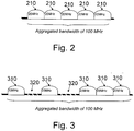
- Frequency resources 210 in Fig. 2 are all located next to each other so as to be contiguous.
- each frequency resource has a bandwidth of 20 MHz.
- the five frequency resources 210 shown in Fig. 2 aggregate to an aggregated bandwidth of 100 MHz.
- the frequency resource aggregation shown in Fig. 2 requires that the operator has access to a contiguous spectrum allocation which can be divided to achieve the number of aggregated frequency resources. While in the drawings frequency resources are shown having a bandwidth of 20 MHz, this is for purpose of illustrating a backwards compatible spectrum allocation. Generally, individual frequency resources may have any bandwidth depending upon the number of included subcarriers.
- LTE-Advanced may also support aggregation of non-contiguous spectrum fragments, which may be referred to as spectrum aggregation, an example of which is illustrated in Fig. 3 .
- spectrum aggregation an example of which is illustrated in Fig. 3 .
- five frequency resources 210 are spectrum aggregated to provide an aggregated bandwidth of 100 MHz.
- One or more frequency resources 210 are separated by spectrum gaps 320 which separate the one or more frequency resources 210 such that those frequency resources 210 separated by spectrum gaps 320 are not contiguous.
- Spectrum aggregation allows for the flexible addition of spectra for transmission. For example, an operator may bring into use different spectrum fragments over time depending upon availability for use by the operator.
- the DFTS-OFDM property of a relatively low power amplification metric should be maintained as much as possible when extending the transmission bandwidth across multiple frequency resources, as for example, part of achieving or adding spectra to an LTE-Advanced system (e.g., having a spectrum allocation such as that shown in Fig. 3 ).
- LTE-Advanced system e.g., having a spectrum allocation such as that shown in Fig. 3
- the structure of transmitter stage 100 of Fig. 1 may be generalized to transmit on one or more distinct frequency resources as shown in Fig. 4 .
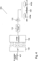
- Fig. 4 is a schematic illustration of an example of such a generalized transmitter stage 400 operable to be compliant with LTE-Advanced by transmitting on multiple frequency resources.
- DFT coder 105 is coupled to OFDM modulator 110 which in turn is coupled to power amplifier 120 through a cyclic-prefix insertion stage 115 operable to insert a cyclic prefix in the output from OFDM modulator 110 before the output is amplified by power amplifier 120 for transmission over different frequency resources 410a, 410b.
- transmitter stage 400 may be operable to receive modulation symbols 401 for transmission on frequency resources 410a, 410b substantially simultaneously.
- frequency resources 410a and 410b are separated by spectrum gap 420 and are hence non-contiguous.
- each frequency resource 410 has a bandwidth of 20 MHz, thus the spectrum aggregation of the two frequency resources yields a total bandwidth of 40 MHz.
- DFT coder 105 and OFDM modulator 110 are scaled to match the larger bandwidth.
- the output of DFT coder 105 is connected to the input of OFDM modulator 110. Because the two frequency resources 410 are not contiguous in frequency, zeros will be input to OFDM modulator 110 to allow for gap 420.
- the control signaling on the Physical Uplink Control Channel may be located at each of the band edges of the LTE uplink, that is, for example, at the band edges of each frequency resource.
- Fig. 4 The structure shown in Fig. 4 is sometimes referred to as Clustered DFTS-OFDM (CL-DFTS-OFDM), where the term clustered refers to the fact that the frequency resources are not necessarily contiguous in frequency but located close to each other.
- the power amplifier metric of the generated signal is higher than that of conventional DFTS-OFDM, as shown, for example, in Fig. 1 , but still low compared to OFDM and increases with the number of clusters.
- a technique for transmitting data over a channel having a predetermined channel quality estimate is known.
- an input data stream to be transmitted is split-up into a plurality of data sub-streams.
- Each of the plurality of data sub-streams is processed into a plurality of symbol subsets by selecting a certain scheme of coded-modulation and each of the plurality of symbol subsets is processed via a plurality of separate Discrete Fourier Transforms (DFTs), in order to obtain a plurality of DFT-precoded data sub-streams.
- DFTs Discrete Fourier Transforms
- Each of the DFT-precoded data sub-stream is then allocated in a frequency resource block via a sub-carrier mapping module, so that for each data sub-stream the selected scheme of coded-modulation is chosen in dependence of the values of the channel quality estimate.
- LTE-Advanced systems are designed to transmit across bandwidths and spectra exceeding 20 MHz.
- the bandwidth or spectrum transmitted upon by an LTE-Advanced system is separated into frequency resources (sometimes called "component carriers") which are themselves backwards compatible.
- a frequency resource may be a component carrier as utilized by an LTE legacy system.
- a component carrier, and thus a frequency resource may have a bandwidth up to 20 MHz and may be composed of resource blocks (comprising sub-carriers) which may be transmitted over.
- a frequency resource may be thought of as a series of resource blocks having a bandwidth spanning a portion of a spectrum and existing for a span of N consecutive symbols in the time domain.
- Such time domain symbols may be OFDM (e.g., SC-FDMA) symbols, and the bandwidth of the resource block may span or include M consecutive subcarriers.
- a resource block is a block of NxM resource elements. Accordingly, LTE-Advanced systems have the potential to transmit upon multiple frequency resources, the individual frequency resources having the potential for different bandwidths. Examples of resource blocks are further discussed in the 3GPP Technical Specification 36.211 V8.7.0 (2009-05 ).
- transmitter stage 100 depicted in Fig. 1 may be generalized to allow for transmission on multiple frequency resources substantially simultaneously, as, for example, shown in Fig. 4 .
- a generalized transmitter stage such as that shown in Fig. 4 , exhibits an increasing power amplifier metric as the number of frequency resources scheduled for or handled by the transmitter increases.
- the increasing power amplifier metric requires that a correspondingly larger power back-off has to be built into the power amplifier of the generalized transmitter stage shown in Fig. 4 . Building such a larger power back-off into a transmitter stage increases the overall size of the transmitter stage, thus undesirably bulking up the transmitter and causing increased power consumption.
- the following embodiments apply a DFT coding per set of frequency resources as will be discussed below with reference to Figs. 5 to 7 . Because numerous frequency resources are divided into sets of frequency resources, each set of frequency resources has a limited number of frequency resources. Thus, DFT coding applied to a set of frequency resources is applied to a limited number of frequency resources.
- the transmitter stage may also include multiple power amplifiers. Output for transmission over each set of frequency resources may be amplified at different power amplifiers such that each set of frequency resources is associated with an individual power amplifier and output transmitted over the set of frequency resources amplified by that amplifier. By amplifying output to be transmitted on sets of frequency resources per associated power amplifier, the power amplifier metric per power amplifier may be kept relatively low. Thus, the power back-off built into the power amplifier(s) may be reduced. In one aspect, reducing the number of non-contiguous frequency resources that are encoded by a single DFT reduces the power amplifier metric for the associated power amplifier.
- a terminal operable to transmit on multiple frequency resources such as, for example, in the uplink.
- the frequency resources are divided into sets such that a limited number of frequency resources form a set: output to be transmitted on each set will later be amplified for transmission using different power amplifiers, one power amplifier per set, as discussed above.
- Frequency resources in each set are transmitted on utilizing clustered DFTS-OFDM (CL-DFTS-OFDM) with different CL-DFTS-OFDM modulators used for the different sets.
- CL-DFTS-OFDM clustered DFTS-OFDM
- Such a structure can be referred to as Multi-Carrier CL-DFTS-OFDM (MC-CL-DFTS-OFDM).
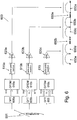
- Fig. 6 schematically illustrates an example of such an MC-CL-DFTS-OFDM system that may be implemented in a terminal such as a mobile telephone, a data card or a portable computer.
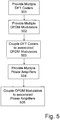
- Fig. 5 is a flow diagram of a method embodiment for operating a transmitter stage 600 as shown in Fig. 6 .
- multiple DFT coders 605 are provided.
- multiple OFDM modulators 610 are likewise provided.
- the DFT coders 605 are coupled to their respective associated OFDM modulators 610.
- multiple power amplifiers are provided and at step 505, the OFDM modulators 610 are coupled to their respective associated power amplifiers 620.
- each DFT coder 605 is coupled to an associated OFDM modulator 610 which in turn is coupled to an associated power amplifier 620 through a cyclic-prefix insertion stage 615.
- Each cyclic-prefix insertion stage 615 is operable to insert a cyclic prefix in the output from the respective OFDM modulator 610 before the output is amplified by the power amplifier 620 associated with the respective OFDM modulator 610.
- each individual power amplifier 620 amplifies OFDM modulator output for transmission over a set of frequency resources.
- the DFT coding of DFT coders 605 is applied per set of frequency resources such that modulation symbols coded by a DFT coder 605 are transmitted on a set of frequency resources located closely to each other in frequency (e.g., in the same frequency band).
- a DFT coding is applied per set of frequency resources and data output on a set of frequency resources is individually amplified by an associated power amplifier.
- Each set of frequency resources can have a limited number of frequency resources such that a DFT coding and corresponding OFDM modulation is applied per a limited set of frequency resources.
- the power amplification metric is reduced. More particularly, in one aspect, reducing the number of non-contiguous frequency resources coded with a DFT reduces the power amplification metric. This reduces the amount of back-off required in individual power amplifiers 620 receiving output from OFDM modulators 610.
- the frequency resources forming a set of frequency resources are contiguous frequency resources in the same frequency band. This may also reduce the power amplification metric.
- demultiplexing stage 601 can supply modulation symbols to each of DFT coders 605 such that each DFT coder 605 may be operable to output coded modulation symbols to its associated OFDM modulator 610 to allow the OFDM modulators 610 to output OFDM symbols for transmission on frequency resources substantially simultaneously.
- demultiplexing stage 601 may supply modulation symbols to DFT coder 605b.
- DFT coder 605b may apply a DFT coding to the modulation symbols and pass the DFT-coded modulation symbols on to associated OFDM modulator 610b. OFDM modulator 610b may then output OFDM symbols for transmission on frequency resources 650b and 650c.
- Fig. 7 is a flow diagram of a method embodiment for transmitting modulation symbols, which may be performed utilizing a transmitter stage such as transmitter stage 600 shown in Fig. 6 .
- a DFT coding is applied by DFT coders 605 per set of symbols to be transmitted on the associated set of frequency resources.
- OFDM modulation is applied by the respective OFDM modulators 610 per set of DFT coded symbols to output sets of OFDM symbols for transmission on sets of frequency resources.
- a cyclic-prefix is inserted at cyclic-prefix insertion stage 615.
- power amplifiers 620 amplify modulator output for transmission over sets of frequency resources such that each power amplifier 620 amplifies output for transmission over an associated set of frequency resources.
- power amplifier 620a amplifies output from OFDM modulator 610a for transmission over frequency resource 650a.
- Power amplifier 620b amplifies output from OFDM modulator 610b for transmission over the set of frequency resources comprising frequency resource 650b and frequency resource 650c.
- Power amplifier 620c amplifies output from OFDM modulator 610c for transmission over the set of frequency resources comprising frequency resource 650d and frequency resource 650e. Because the sets of frequency resources include a limited number of frequency resources, each DFT coding, OFDM modulation and power amplification is applied per a limited number of frequency resources, reducing the power amplification metric per power amplifier.
- Frequency resource 650a is separated from the frequency resources associated with power amplifier 650b by gap 660a.
- the frequency resources associated with power amplifier 650b are separated from the frequency resources associated with power amplifier 650c by gap 660b.
- frequency resources 650 may be spectrum aggregated to achieve an aggregated bandwidth for the transmission of modulation signals or other data utilizing transmission stage 600 of Fig. 6 .
- a transmitter stage can be selected or configured which approximates one of the transmitter stages shown in Fig. 4 or Fig. 6 .
- the selection of which structure to use for an uplink transmission may depend on the number of frequency resources that a terminal is scheduled to transmit upon. For example, in the event that a terminal has sufficient individual power amplifiers to amplify modulation output for transmission on each scheduled frequency resource individually, output to be transmitted on the frequency resources may be individually amplified, one frequency resource per power amplifier, as opposed to being amplified per sets of more than one frequency resources.
- the structure to be used is determined based on the number of power amplifiers allocated per user.
- the terminal and the network may negotiate which structure to use for different scenarios. For example, in a scenario where the number of frequency resources a terminal is scheduled to transmit on is less than or equal to the available power amplifiers, the power amplifiers may each amplify modulator output for transmission over a single frequency resource, even if the spectrum is contiguous.
- the techniques disclosed herein provide an approach for transmitting and a transmitter stage yielding a power amplifier metric that is low when transmitting utilizing multiple frequency resources in an LTE-Advanced system. Further advantages of the disclosed techniques include maintaining a low power amplifier metric when transmitting over either frequency resource or spectrum aggregation aggregated spectra.
Landscapes
- Physics & Mathematics (AREA)
- Discrete Mathematics (AREA)
- General Physics & Mathematics (AREA)
- Mathematical Physics (AREA)
- Engineering & Computer Science (AREA)
- Computer Networks & Wireless Communication (AREA)
- Signal Processing (AREA)
- Transmitters (AREA)
- Amplifiers (AREA)
Description
- The present invention relates to a method and arrangement in a telecommunication system, in particular to a technique for handling the aggregation of multiple frequency resources in an evolved Universal Terrestrial Radio Access Network or similar telecommunication network.
- The Long-Term Evolution (LTE) of the Universal Terrestrial Radio Access Network (UTRAN), also denoted E-UTRAN, as standardized in Rel-8 of the 3rd Generation Partnership Project (3GPP) specifications supports transmission bandwidths up to 20 MHz. In the downlink, LTE uses conventional Orthogonal Frequency Division Multiplexing (OFDM) as the transmission scheme. OFDM provides benefits, e.g. it is robust to time dispersion, but has also some drawbacks, most notably a relatively high peak-to-average power ratio (PAR) of the transmitted signal.
- Power amplifiers have to be designed to meet peak transmission power requirements while still meeting network requirements regarding the average output power (for example, determining the achievable data rate and coverage). The difference between the peak power and the average power determines the so-called amplifier back-off and is thus a measure on how much the power amplifier needs to be "over dimensioned" (or, equivalently, how much is lost in coverage when using the same amplifier but a lower-performance transmission scheme).
- A high PAR implies a larger power back-off in the power amplifier, that is, the power amplifier cannot be used to its full extent. The Cubic Metric (CM) is another, generally more accurate metric, that can be used to represent the amount of back-off required in the power amplifier. In the following, the term "power amplifier metric" (denoting, e.g., PAR, CM, or any other appropriate measure) is used which shall be generally understood as a measure representing the impact of the difference or ratio between the peak power and the average power on the power amplifier design.
- In the uplink, a high power amplifier metric can lead to reduced coverage, higher battery consumption, and/or more expensive implementation. Therefore, for the uplink, LTE has adopted a single-carrier transmission scheme with low power amplifier metric known as DFT (Discrete Fourier Transform)-spread OFDM (DFTS-OFDM) or DFT-precoded OFDM (sometimes also referred to as Single-Carrier Frequency Division Multiple Access, or SC-FDMA). SC-FDMA exhibits a significantly lower PAR than OFDM.
-
Fig. 1 is a schematic illustration of an example of an SC-FDMA transmitter stage 100 operable to transmit on a single carrier according to the LTE transmission scheme. Intransmitter stage 100,DFT coder 105 is coupled toOFDM modulator 110 which in turn is coupled topower amplifier 120 through a cyclic-prefix insertion stage 115 operable to insert a cyclic prefix in the output fromOFDM modulator 110 before the output is amplified bypower amplifier 120 for transmission overcarrier 125. As shown inFig. 1 ,carrier 125 has a bandwidth of 20 MHz. Carrier 125 may be referred to as a frequency resource for the transmission of a set of data blocks. While inFig. 1 ,carrier 125 is shown as having a 20 MHz bandwidth, other bandwidths are possible in the LTE transmission scheme, and the bandwidth may vary (e.g., depending on the number of symbols to be transmitted via carrier 125). -
Modulation symbols 101, shown inFig. 1 as M modulation symbols, are input toDFT coder 105 and the output ofDFT coder 105 is mapped to selective inputs ofOFDM modulator 110. Examples of OFDM modulators comprise an Inverse Fast Fourier Transform (IFFT). The output ofOFDM modulator 110 contains the data of modulation symbols 101 ("OFDM symbols") and is amplified bypower amplifier 120 for transmission overcarrier 125. - The DFT size, for example the size of the DFT performed by
DFT coder 105, determines the instantaneous bandwidth of the transmitted signal while the exact mapping of the DFT coder output to the input of theOFDM modulator 110 determines the position of the transmitted signal within the overall uplink transmission bandwidth. Similar to conventional OFDM, a cyclic prefix is inserted subsequent to OFDM modulation. The use of a cyclic prefix allows for straightforward application of low-complexity frequency-domain equalization at the receiver side. - In order to meet requirements for International Mobile Telecommunications-Advanced (IMT-Advanced), 3GPP has initiated work on LTE-Advanced. One aspect of LTE-Advanced is to develop support for bandwidths larger than 20 MHz. Another aspect is to assure backward compatibility with LTE Rel-8. Backward compatibility also includes spectrum compatibility. Thus, in one exemplary implementation, to allow for backwards compatibility with LTE Rel-8, an LTE-Advanced spectrum or carrier that is wider than 20 MHz may appear as a number of separate LTE carriers to an LTE Rel-8 terminal. Separate LTE carriers may be referred to as different frequency resources. Thus, each Rel-8 LTE carrier can be referred to as a single frequency resource.
- For early LTE-Advanced deployments, it can be expected that there will be a smaller number of LTE-Advanced-capable terminals compared to many LTE legacy terminals. Therefore, it is desirable to enable the use of frequency resources such that legacy terminals can be scheduled in all parts of the available wideband LTE-Advanced bandwidth. The straightforward way to allow for such optimal backwards compatibility would be by means of frequency resource aggregation. Frequency resource aggregation implies that an LTE-Advanced terminal can receive and transmit on multiple frequency resources, where each frequency resource may have, or may be modified to have, the same structure as a Rel-8 LTE carrier.
- An example of the aggregation of multiple frequency resources is illustrated in
Fig. 2 .Frequency resources 210 inFig. 2 are all located next to each other so as to be contiguous. In the specific example ofFig. 2 , each frequency resource has a bandwidth of 20 MHz. Together, the fivefrequency resources 210 shown inFig. 2 aggregate to an aggregated bandwidth of 100 MHz. The frequency resource aggregation shown inFig. 2 requires that the operator has access to a contiguous spectrum allocation which can be divided to achieve the number of aggregated frequency resources. While in the drawings frequency resources are shown having a bandwidth of 20 MHz, this is for purpose of illustrating a backwards compatible spectrum allocation. Generally, individual frequency resources may have any bandwidth depending upon the number of included subcarriers. - To provide additional spectrum flexibility, LTE-Advanced may also support aggregation of non-contiguous spectrum fragments, which may be referred to as spectrum aggregation, an example of which is illustrated in
Fig. 3 . In the particular example ofFig. 3 , fivefrequency resources 210 are spectrum aggregated to provide an aggregated bandwidth of 100 MHz. One ormore frequency resources 210 are separated byspectrum gaps 320 which separate the one ormore frequency resources 210 such that thosefrequency resources 210 separated byspectrum gaps 320 are not contiguous. Spectrum aggregation allows for the flexible addition of spectra for transmission. For example, an operator may bring into use different spectrum fragments over time depending upon availability for use by the operator. - The DFTS-OFDM property of a relatively low power amplification metric should be maintained as much as possible when extending the transmission bandwidth across multiple frequency resources, as for example, part of achieving or adding spectra to an LTE-Advanced system (e.g., having a spectrum allocation such as that shown in
Fig. 3 ). To achieve a system operable to implement LTE-Advanced by extending the transmission bandwidth across multiple frequency resources, the structure oftransmitter stage 100 ofFig. 1 may be generalized to transmit on one or more distinct frequency resources as shown inFig. 4 . -
Fig. 4 is a schematic illustration of an example of such ageneralized transmitter stage 400 operable to be compliant with LTE-Advanced by transmitting on multiple frequency resources. Intransmitter stage 400,DFT coder 105 is coupled toOFDM modulator 110 which in turn is coupled topower amplifier 120 through a cyclic-prefix insertion stage 115 operable to insert a cyclic prefix in the output fromOFDM modulator 110 before the output is amplified bypower amplifier 120 for transmission overdifferent frequency resources - As shown in
Fig. 4 ,transmitter stage 400 may be operable to receivemodulation symbols 401 for transmission onfrequency resources Fig. 4 ,frequency resources spectrum gap 420 and are hence non-contiguous. As also shown inFig. 4 , each frequency resource 410 has a bandwidth of 20 MHz, thus the spectrum aggregation of the two frequency resources yields a total bandwidth of 40 MHz. - In the system of
Fig. 4 ,DFT coder 105 andOFDM modulator 110 are scaled to match the larger bandwidth. The output ofDFT coder 105 is connected to the input ofOFDM modulator 110. Because the two frequency resources 410 are not contiguous in frequency, zeros will be input toOFDM modulator 110 to allow forgap 420. In one embodiment of a possible future extension, the control signaling on the Physical Uplink Control Channel (PUCCH) may be located at each of the band edges of the LTE uplink, that is, for example, at the band edges of each frequency resource. - The structure shown in
Fig. 4 is sometimes referred to as Clustered DFTS-OFDM (CL-DFTS-OFDM), where the term clustered refers to the fact that the frequency resources are not necessarily contiguous in frequency but located close to each other. The power amplifier metric of the generated signal is higher than that of conventional DFTS-OFDM, as shown, for example, inFig. 1 , but still low compared to OFDM and increases with the number of clusters. - From
EP 1 928 115 A1 a technique for transmitting data over a channel having a predetermined channel quality estimate is known. For this purpose, an input data stream to be transmitted is split-up into a plurality of data sub-streams. Each of the plurality of data sub-streams is processed into a plurality of symbol subsets by selecting a certain scheme of coded-modulation and each of the plurality of symbol subsets is processed via a plurality of separate Discrete Fourier Transforms (DFTs), in order to obtain a plurality of DFT-precoded data sub-streams. Each of the DFT-precoded data sub-stream is then allocated in a frequency resource block via a sub-carrier mapping module, so that for each data sub-stream the selected scheme of coded-modulation is chosen in dependence of the values of the channel quality estimate. - In the publication "Performance and implementation of clustered-OFDM for wireless communications", Mobile Networks and Applications 2, (1997), p. 305-314, a wireless transmission technique over adjacent sub-channels is taught. In this context, a clustered-OFDM system is presented, in which OFDM clusters are FFTed and power amplified on a per cluster basis such that there is a one-to-one correspondence between cluster and power amplifier.
- Accordingly, it is an object to provide a technique to reduce the power amplifier metric in an LTE-Advanced or similar system relying at least in part on non-contiguous frequency resources.
- There is provided a method according to the independent claim 1 and further detailed in dependent claims 2-8. A corresponding apparatus is provided in independent claim 9. Additionally, a corresponding computer program product is provided in independent claim 10.
The present invention is defined and limited only by the scope of the appended claims. In the following, any embodiment(s) referred to and not falling within the scope of said claims is (are) to be interpreted as example(s) useful for understanding the invention. The techniques presented herein may be realized in the form of software, in the form of hardware, or using a combined software/hardware approach. As regards a software aspect, a computer program product comprising program code portions for performing the steps presented herein when the computer program product is run on one or more computing devices may be provided. The computer program product may be stored on a computer-readable recording medium such as a memory chip, a CD-ROM, a hard disk, and so on. Moreover, the computer program product may be provided for download onto such a recording medium. - Further aspects and advantages of the techniques presented herein will become apparent from the following description of embodiments and the accompanying drawings, wherein:
-
Fig. 1 schematically illustrates an example transmitter implementation for transmitting on a frequency resource. -
Fig. 2 illustrates an example of carrier aggregation over a contiguous spectrum. -
Fig. 3 illustrates an example of carrier aggregation over a non-contiguous spectrum. -
Fig. 4 schematically illustrates an example transmitter implementation for transmitting on multiple frequency resources. -
Fig. 5 shows a flow diagram of a method embodiment for implementing a transmitter operable to transmit on multiple frequency resources. -
Fig. 6 schematically illustrates an embodiment of a transmitter implementation for transmitting on multiple frequency resources. -
Fig. 7 shows a flow diagram of a method embodiment for transmitting on multiple frequency resources. - In the following description of preferred embodiments, for purposes of explanation and not limitation, specific details are set forth (such as particular transmitter stage components and sequences of steps) in order to provide a thorough understanding of the present invention. It will be apparent to one skilled in the art that the present invention is defined and limited only by the scope of the appended claims. It is evident that the techniques presented herein are not restricted to be implemented in LTE-Advanced systems exemplarily described hereinafter but may also be used in conjunction with other telecommunication systems.
- Moreover, those skilled in the art will appreciate that the functions and steps explained herein below may be implemented using software functioning in conjunction with a programmed microprocessor, an Application Specific Integrated Circuit (ASIC), a Digital Signal Processor (DSP) or a general purpose computer. It will also be appreciated that while the following embodiments will primarily be described in context with methods and devices, the invention may also be embodied in a computer program product as well as in a system comprising a computer processor and a memory coupled to the processor, wherein the memory is encoded with one or more programs that may perform the functions and steps disclosed herein.
- LTE-Advanced systems are designed to transmit across bandwidths and spectra exceeding 20 MHz. In order to allow for backwards compatibility, the bandwidth or spectrum transmitted upon by an LTE-Advanced system is separated into frequency resources (sometimes called "component carriers") which are themselves backwards compatible. In one scenario, a frequency resource may be a component carrier as utilized by an LTE legacy system. In an implementation example, a component carrier, and thus a frequency resource, may have a bandwidth up to 20 MHz and may be composed of resource blocks (comprising sub-carriers) which may be transmitted over.
- More generally, a frequency resource may be thought of as a series of resource blocks having a bandwidth spanning a portion of a spectrum and existing for a span of N consecutive symbols in the time domain. Such time domain symbols may be OFDM (e.g., SC-FDMA) symbols, and the bandwidth of the resource block may span or include M consecutive subcarriers. Thus a resource block is a block of NxM resource elements. Accordingly, LTE-Advanced systems have the potential to transmit upon multiple frequency resources, the individual frequency resources having the potential for different bandwidths. Examples of resource blocks are further discussed in the 3GPP Technical Specification 36.211 V8.7.0 (2009-05).
- As described previously in the Background Section, to achieve an LTE-Advanced system,
transmitter stage 100 depicted inFig. 1 may be generalized to allow for transmission on multiple frequency resources substantially simultaneously, as, for example, shown inFig. 4 . As further previously discussed, a generalized transmitter stage, such as that shown inFig. 4 , exhibits an increasing power amplifier metric as the number of frequency resources scheduled for or handled by the transmitter increases. The increasing power amplifier metric requires that a correspondingly larger power back-off has to be built into the power amplifier of the generalized transmitter stage shown inFig. 4 . Building such a larger power back-off into a transmitter stage increases the overall size of the transmitter stage, thus undesirably bulking up the transmitter and causing increased power consumption. - To overcome the problem of an LTE-Advanced system transmitter exhibiting an increasing power amplifier metric as the number of frequency resources which are scheduled for the transmitter stage increases, the following embodiments apply a DFT coding per set of frequency resources as will be discussed below with reference to
Figs. 5 to 7 . Because numerous frequency resources are divided into sets of frequency resources, each set of frequency resources has a limited number of frequency resources. Thus, DFT coding applied to a set of frequency resources is applied to a limited number of frequency resources. - The transmitter stage may also include multiple power amplifiers. Output for transmission over each set of frequency resources may be amplified at different power amplifiers such that each set of frequency resources is associated with an individual power amplifier and output transmitted over the set of frequency resources amplified by that amplifier. By amplifying output to be transmitted on sets of frequency resources per associated power amplifier, the power amplifier metric per power amplifier may be kept relatively low. Thus, the power back-off built into the power amplifier(s) may be reduced. In one aspect, reducing the number of non-contiguous frequency resources that are encoded by a single DFT reduces the power amplifier metric for the associated power amplifier.
- A terminal operable to transmit on multiple frequency resources, such as, for example, in the uplink, is provided. The frequency resources are divided into sets such that a limited number of frequency resources form a set: output to be transmitted on each set will later be amplified for transmission using different power amplifiers, one power amplifier per set, as discussed above. Frequency resources in each set are transmitted on utilizing clustered DFTS-OFDM (CL-DFTS-OFDM) with different CL-DFTS-OFDM modulators used for the different sets. Such a structure can be referred to as Multi-Carrier CL-DFTS-OFDM (MC-CL-DFTS-OFDM).
Fig. 6 schematically illustrates an example of such an MC-CL-DFTS-OFDM system that may be implemented in a terminal such as a mobile telephone, a data card or a portable computer. -
Fig. 5 is a flow diagram of a method embodiment for operating atransmitter stage 600 as shown inFig. 6 . Atstep 501,multiple DFT coders 605 are provided. Atstep 502, multiple OFDM modulators 610 are likewise provided. Atstep 503, theDFT coders 605 are coupled to their respective associated OFDM modulators 610. Atstep 504, multiple power amplifiers are provided and atstep 505, the OFDM modulators 610 are coupled to their respective associated power amplifiers 620. Thus yielding thetransmitter stage 600 shown inFig. 6 . - Referring to
Fig. 6 , intransmitter stage 600, eachDFT coder 605 is coupled to an associated OFDM modulator 610 which in turn is coupled to an associated power amplifier 620 through a cyclic-prefix insertion stage 615. Each cyclic-prefix insertion stage 615 is operable to insert a cyclic prefix in the output from the respective OFDM modulator 610 before the output is amplified by the power amplifier 620 associated with the respective OFDM modulator 610. - As can be seen from
Fig. 6 , each individual power amplifier 620 amplifies OFDM modulator output for transmission over a set of frequency resources. As can further be seen fromFig. 6 , the DFT coding ofDFT coders 605 is applied per set of frequency resources such that modulation symbols coded by aDFT coder 605 are transmitted on a set of frequency resources located closely to each other in frequency (e.g., in the same frequency band). Thus, a DFT coding is applied per set of frequency resources and data output on a set of frequency resources is individually amplified by an associated power amplifier. Each set of frequency resources can have a limited number of frequency resources such that a DFT coding and corresponding OFDM modulation is applied per a limited set of frequency resources. By applying DFT coding and OFDM modulation per a limited number of frequency resources, the power amplification metric is reduced. More particularly, in one aspect, reducing the number of non-contiguous frequency resources coded with a DFT reduces the power amplification metric. This reduces the amount of back-off required in individual power amplifiers 620 receiving output from OFDM modulators 610. - In one optional aspect, the frequency resources forming a set of frequency resources are contiguous frequency resources in the same frequency band. This may also reduce the power amplification metric.
- As shown in
Fig. 6 , a stream of modulation symbols is provided toDFT coders 605 by ademultiplexing stage 601. In an optional aspect,demultiplexing stage 601 can supply modulation symbols to each ofDFT coders 605 such that eachDFT coder 605 may be operable to output coded modulation symbols to its associated OFDM modulator 610 to allow the OFDM modulators 610 to output OFDM symbols for transmission on frequency resources substantially simultaneously. For example,demultiplexing stage 601 may supply modulation symbols toDFT coder 605b.DFT coder 605b may apply a DFT coding to the modulation symbols and pass the DFT-coded modulation symbols on to associatedOFDM modulator 610b.OFDM modulator 610b may then output OFDM symbols for transmission onfrequency resources -
Fig. 7 is a flow diagram of a method embodiment for transmitting modulation symbols, which may be performed utilizing a transmitter stage such astransmitter stage 600 shown inFig. 6 . - At
step 701, a DFT coding is applied byDFT coders 605 per set of symbols to be transmitted on the associated set of frequency resources. Atstep 702, OFDM modulation is applied by the respective OFDM modulators 610 per set of DFT coded symbols to output sets of OFDM symbols for transmission on sets of frequency resources. Atstep 703, a cyclic-prefix is inserted at cyclic-prefix insertion stage 615. Atstep 704, power amplifiers 620 amplify modulator output for transmission over sets of frequency resources such that each power amplifier 620 amplifies output for transmission over an associated set of frequency resources. - Referring to
Fig. 6 ,power amplifier 620a amplifies output fromOFDM modulator 610a for transmission over frequency resource650a. Power amplifier 620b amplifies output fromOFDM modulator 610b for transmission over the set of frequency resources comprisingfrequency resource 650b and frequency resource650c. Power amplifier 620c amplifies output fromOFDM modulator 610c for transmission over the set of frequency resources comprisingfrequency resource 650d andfrequency resource 650e. Because the sets of frequency resources include a limited number of frequency resources, each DFT coding, OFDM modulation and power amplification is applied per a limited number of frequency resources, reducing the power amplification metric per power amplifier. -
Frequency resource 650a is separated from the frequency resources associated withpower amplifier 650b bygap 660a. Similarly, the frequency resources associated withpower amplifier 650b are separated from the frequency resources associated withpower amplifier 650c bygap 660b. Thus, frequency resources 650 may be spectrum aggregated to achieve an aggregated bandwidth for the transmission of modulation signals or other data utilizingtransmission stage 600 ofFig. 6 . - According to a further aspect, a transmitter stage can be selected or configured which approximates one of the transmitter stages shown in
Fig. 4 orFig. 6 . The selection of which structure to use for an uplink transmission may depend on the number of frequency resources that a terminal is scheduled to transmit upon. For example, in the event that a terminal has sufficient individual power amplifiers to amplify modulation output for transmission on each scheduled frequency resource individually, output to be transmitted on the frequency resources may be individually amplified, one frequency resource per power amplifier, as opposed to being amplified per sets of more than one frequency resources. In an alternative embodiment, the structure to be used is determined based on the number of power amplifiers allocated per user. - In addition to or as yet another aspect, the terminal and the network may negotiate which structure to use for different scenarios. For example, in a scenario where the number of frequency resources a terminal is scheduled to transmit on is less than or equal to the available power amplifiers, the power amplifiers may each amplify modulator output for transmission over a single frequency resource, even if the spectrum is contiguous.
- By applying DFT coding per set of limited number of frequency resources, for example to a limited number of non-contiguous frequency resources, or amplifying sets of frequency resources per power amplifier, the advantage of a minimized power amplifier metric is achieved, thus allowing for smaller power amplifiers and allowing for a reduction in power consumption and power amplifier size. Thus the techniques disclosed herein provide an approach for transmitting and a transmitter stage yielding a power amplifier metric that is low when transmitting utilizing multiple frequency resources in an LTE-Advanced system. Further advantages of the disclosed techniques include maintaining a low power amplifier metric when transmitting over either frequency resource or spectrum aggregation aggregated spectra.
- The achievement of a low power amplifier metric over the addition of multiple frequency resources allows for an inherently scalable system. Furthermore, because individual frequency resources are themselves backwards compatible in that they allow for use with legacy devices which may utilize a single frequency resource, a backwards compatible and scalable system which minimizes the power amplifier metric is achieved. In addition, this allows for the utilization of non-contiguous spectrum segments, thus enabling for the flexible addition of spectra or changing spectrum use, enhancing system flexibility.
- It is believed that many advantages of the present invention will be fully understood from the forgoing description, and it will be apparent that various changes may be made in the form, construction and arrangement of the exemplary aspects thereof without departing from the scope of the invention or without sacrificing all of its advantages. Because the invention can be varied in many ways, it will be recognized that the invention should be limited only by the scope of the following claims.
Claims (11)
- A method of transmitting modulation symbols on multiple component carriers (650), comprising:applying (701), to two or more sets of modulation symbols, a Discrete Fourier Transform, DFT, coding (605; 605b; 605a) per said set of modulation symbols, wherein a first set of said two or more sets of modulation symbols is to be transmitted on a set of component carriers (410a, 410b; 650b, 650c; 650d, 650e) scheduled for a same power amplifier (620b; 620c), wherein said component carriers of said set of component carriers are non-contiguous relative to each other;applying (702) Orthogonal Frequency Division Multiplexing, OFDM, modulation per said first and second sets of DFT coded modulation symbols to output a first set of OFDM symbols for transmission on said set of component carriers, and output a second set of OFDM symbols for transmission on at least one additional component carrier (650a) distinct from said set of component carriers; andapplying (704) power amplification per said set of component carriers and per said at least one additional component carrier.
- The method of claim 1, wherein each of the component carriers has a spectrum bandwidth spanning a frequency range compatible in bandwidth to a telecommunication system spectrum bandwidth.
- The method of claim 2, wherein the spectrum bandwidth is defined by the spectrum bandwidth of a legacy telecommunication system.
- The method of any of claims 1 to 3, further comprising demultiplexing a stream of modulation symbols to form said two or more sets of modulation symbols.
- The method of any of claims 1 to 4, wherein the component carriers of said set of component carriers are non-contiguous with said at least one additional component carrier.
- The method of any of claims 1 to 5, wherein the method is implemented in a terminal, and comprises negotiating, with a network, usage of said method so as to transmit said network over said terminal utilizing said method.
- The method of any of claims 1 to 6, further comprising inserting (703) cyclic-prefixes in OFDM modulated output.
- The method of any of claims 1 to 7, wherein each component carrier comprises a series of resource blocks having a bandwidth spanning a portion of a spectrum and existing for a span of N consecutive symbols in the time domain.
- An apparatus (600) being configured to perform the steps of any of claims 1 to 8.
- A computer program product comprising program code portions comprising instructions to perform, when run on a computer, the steps of any of claims 1 to 8.
- The computer program product of claim 10, stored on a computer-readable recording medium.
Applications Claiming Priority (2)
| Application Number | Priority Date | Filing Date | Title |
|---|---|---|---|
| US9836208P | 2008-09-19 | 2008-09-19 | |
| EP09778193A EP2327192B1 (en) | 2008-09-19 | 2009-08-28 | A transmitter stage and a corresponding method for transmitting signals on multiple frequency resources in a telecommunication system |
Related Parent Applications (1)
| Application Number | Title | Priority Date | Filing Date |
|---|---|---|---|
| EP09778193A Division EP2327192B1 (en) | 2008-09-19 | 2009-08-28 | A transmitter stage and a corresponding method for transmitting signals on multiple frequency resources in a telecommunication system |
Publications (2)
| Publication Number | Publication Date |
|---|---|
| EP2509269A1 EP2509269A1 (en) | 2012-10-10 |
| EP2509269B1 true EP2509269B1 (en) | 2017-10-04 |
Family
ID=41258315
Family Applications (2)
| Application Number | Title | Priority Date | Filing Date |
|---|---|---|---|
| EP09778193A Active EP2327192B1 (en) | 2008-09-19 | 2009-08-28 | A transmitter stage and a corresponding method for transmitting signals on multiple frequency resources in a telecommunication system |
| EP12005037.2A Not-in-force EP2509269B1 (en) | 2008-09-19 | 2009-08-28 | Signal transmission on mutiple component carriers in a telecommunication system |
Family Applications Before (1)
| Application Number | Title | Priority Date | Filing Date |
|---|---|---|---|
| EP09778193A Active EP2327192B1 (en) | 2008-09-19 | 2009-08-28 | A transmitter stage and a corresponding method for transmitting signals on multiple frequency resources in a telecommunication system |
Country Status (10)
| Country | Link |
|---|---|
| US (2) | US8542645B2 (en) |
| EP (2) | EP2327192B1 (en) |
| JP (1) | JP5507565B2 (en) |
| CN (1) | CN102160349B (en) |
| AR (1) | AR073621A1 (en) |
| DK (1) | DK2509269T3 (en) |
| ES (1) | ES2390409T3 (en) |
| MX (1) | MX2011001993A (en) |
| PL (1) | PL2327192T3 (en) |
| WO (1) | WO2010031493A1 (en) |
Families Citing this family (11)
| Publication number | Priority date | Publication date | Assignee | Title |
|---|---|---|---|---|
| US8542645B2 (en) * | 2008-09-19 | 2013-09-24 | Telefonaktiebolaget Lm Ericsson (Publ) | Technique for transmitting on multiple frequency resources in a telecommunication system |
| JP5219708B2 (en) | 2008-09-22 | 2013-06-26 | 株式会社エヌ・ティ・ティ・ドコモ | Mobile terminal apparatus, radio base station apparatus, radio communication system, and radio communication method |
| AU2009315179B2 (en) | 2008-11-14 | 2013-11-14 | Sun Patent Trust | Wireless communication terminal apparatus, wireless communication base station apparatus, and cluster constellation setting method |
| JP5528123B2 (en) * | 2010-01-05 | 2014-06-25 | シャープ株式会社 | COMMUNICATION DEVICE, COMMUNICATION DEVICE CONTROL PROGRAM, AND INTEGRATED CIRCUIT |
| US8582551B2 (en) * | 2010-05-26 | 2013-11-12 | Intel Corporation | Device, system and method of wireless communication over non-contiguous channels |
| US9991847B2 (en) * | 2010-12-23 | 2018-06-05 | Maxlinear, Inc. | Method and apparatus for broadband data conversion |
| CN102136899B (en) * | 2011-01-20 | 2014-03-26 | 华为技术有限公司 | Usage of discrete spectrum in orthogonal frequency division multiplexing system, and receiving method and device using discrete spectrum |
| EP2587753B1 (en) * | 2011-10-25 | 2013-12-18 | Alcatel Lucent | Component transmitter, transmission stage, transceiver, method for a transmission stage and computer program |
| JP2015095688A (en) * | 2013-11-08 | 2015-05-18 | 日本電信電話株式会社 | Multi-carrier transmitter, multi-carrier transmission circuit, and multi-carrier transmission method |
| US10454739B2 (en) * | 2015-01-23 | 2019-10-22 | Texas Instruments Incorporated | Transmission scheme for SC-FDMA with two DFT-precoding stages |
| KR20190018762A (en) | 2015-03-19 | 2019-02-25 | 스워치 악티엔게젤샤프트 (스워치 쏘시에떼아노님)(스워치 리미 티드) | Spectacles with customisable frame |
Family Cites Families (14)
| Publication number | Priority date | Publication date | Assignee | Title |
|---|---|---|---|---|
| US6334219B1 (en) | 1994-09-26 | 2001-12-25 | Adc Telecommunications Inc. | Channel selection for a hybrid fiber coax network |
| KR100884407B1 (en) * | 2002-10-02 | 2009-02-17 | 삼성전자주식회사 | TDS-OFDM transmission system having 3780-????? ????/??? procseeor and structure of 3780- ?? procseeor |
| US8145251B2 (en) * | 2006-01-23 | 2012-03-27 | Motorola Mobility, Inc. | Power control in schedulable wireless communication terminal |
| US20070173260A1 (en) * | 2006-01-23 | 2007-07-26 | Love Robert T | Wireless communication network scheduling |
| US8102802B2 (en) * | 2006-05-08 | 2012-01-24 | Motorola Mobility, Inc. | Method and apparatus for providing downlink acknowledgments and transmit indicators in an orthogonal frequency division multiplexing communication system |
| US20080025254A1 (en) * | 2006-07-25 | 2008-01-31 | Motorola Inc | Spectrum emission level variation in schedulable wireless communication terminal |
| KR100957311B1 (en) * | 2006-08-11 | 2010-05-13 | 삼성전자주식회사 | Uplink Scheduling Method and Apparatus for Mobile Communication System |
| US8509323B2 (en) * | 2006-08-22 | 2013-08-13 | Motorola Mobility Llc | Resource allocation including a DC sub-carrier in a wireless communication system |
| EP1928115A1 (en) * | 2006-11-30 | 2008-06-04 | Nokia Siemens Networks Gmbh & Co. Kg | Adaptive modulation and coding in a SC-FDMA system |
| US8010070B2 (en) * | 2007-10-09 | 2011-08-30 | Maxlinear, Inc. | Low-complexity diversity using coarse FFT and subband-wise combining |
| KR101597573B1 (en) * | 2008-08-11 | 2016-02-25 | 엘지전자 주식회사 | Method for uplink transmitting a control information |
| KR101549021B1 (en) * | 2008-08-20 | 2015-09-01 | 엘지전자 주식회사 | Precoding method for reduced uplink papr and appratus therefor |
| US8542645B2 (en) * | 2008-09-19 | 2013-09-24 | Telefonaktiebolaget Lm Ericsson (Publ) | Technique for transmitting on multiple frequency resources in a telecommunication system |
| US9172513B2 (en) * | 2010-10-11 | 2015-10-27 | Qualcomm Incorporated | Resource assignments for uplink control channel |
-
2009
- 2009-08-28 US US13/119,512 patent/US8542645B2/en active Active
- 2009-08-28 JP JP2011527230A patent/JP5507565B2/en active Active
- 2009-08-28 EP EP09778193A patent/EP2327192B1/en active Active
- 2009-08-28 ES ES09778193T patent/ES2390409T3/en active Active
- 2009-08-28 EP EP12005037.2A patent/EP2509269B1/en not_active Not-in-force
- 2009-08-28 DK DK12005037.2T patent/DK2509269T3/en active
- 2009-08-28 WO PCT/EP2009/006264 patent/WO2010031493A1/en active Application Filing
- 2009-08-28 MX MX2011001993A patent/MX2011001993A/en active IP Right Grant
- 2009-08-28 PL PL09778193T patent/PL2327192T3/en unknown
- 2009-08-28 CN CN200980137377.9A patent/CN102160349B/en not_active Expired - Fee Related
- 2009-09-18 AR ARP090103607A patent/AR073621A1/en active IP Right Grant
-
2013
- 2013-08-21 US US13/972,293 patent/US8848650B2/en active Active
Non-Patent Citations (1)
| Title |
|---|
| None * |
Also Published As
| Publication number | Publication date |
|---|---|
| DK2509269T3 (en) | 2018-01-08 |
| PL2327192T3 (en) | 2012-12-31 |
| EP2509269A1 (en) | 2012-10-10 |
| EP2327192A1 (en) | 2011-06-01 |
| CN102160349A (en) | 2011-08-17 |
| AR073621A1 (en) | 2010-11-17 |
| EP2327192B1 (en) | 2012-07-11 |
| ES2390409T3 (en) | 2012-11-12 |
| US20130336421A1 (en) | 2013-12-19 |
| JP5507565B2 (en) | 2014-05-28 |
| US20110171966A1 (en) | 2011-07-14 |
| CN102160349B (en) | 2014-04-02 |
| US8848650B2 (en) | 2014-09-30 |
| MX2011001993A (en) | 2011-04-04 |
| WO2010031493A1 (en) | 2010-03-25 |
| US8542645B2 (en) | 2013-09-24 |
| JP2012503384A (en) | 2012-02-02 |
Similar Documents
| Publication | Publication Date | Title |
|---|---|---|
| EP2509269B1 (en) | Signal transmission on mutiple component carriers in a telecommunication system | |
| US7715492B2 (en) | Transmitter and transmission method | |
| Michailow et al. | Low peak-to-average power ratio for next generation cellular systems with generalized frequency division multiplexing | |
| US8406113B2 (en) | Peak-to-average reduction of SC-FDMA signals with frequency mask | |
| EP3529957B1 (en) | Synthesis of near-constant modulus waveform for high frequency transmission | |
| JP5468606B2 (en) | Resource block mapping of symbols with repeated overlap | |
| US11637733B2 (en) | Transmission apparatus, reception apparatus, and communication method | |
| WO2017219788A1 (en) | Signal processing method and device | |
| US8570910B2 (en) | Wireless transmission apparatus and wireless transmission method | |
| US20210328848A1 (en) | Transmissions using discrete spectra | |
| Suarez et al. | LTE transceiver performance analysis in Uplink under various environmental conditions | |
| CN111262805B (en) | Data transmission method, device and system | |
| WO2023284752A1 (en) | Data transmission method and apparatus, data modulation method and apparatus, electronic device, and storage medium | |
| Yadav et al. | PAPR analysis of single carrier FDMA system for uplink wireless transmission | |
| KR102191506B1 (en) | Method and apparatus for processing a transmit signal in communication system | |
| Joshi et al. | Dynamic spectral shaping in LTE-Advanced cognitive radio systems | |
| Montalvo et al. | Comparison and analysis of PAPR reduction techniques in OFDMA and SC-FDMA systems | |
| Singh et al. | Novel companding technique for PAPR reduction in OFDM system | |
| An et al. | PAPR reduction for carrier aggregated uplink in LTE-A system | |
| EP3089416A1 (en) | Wireless communications device providing peak-to-average power ratio (papr) reduction based upon walsh transformation matrix permutations and related methods | |
| KR101565386B1 (en) | PAPR Reduction Method Using Specific PAPR Reduction Signals | |
| Michailow et al. | Generalized Frequency Division Multiplexing: An Alternative Multi-Carrier Technique for Next Generation Cellular Systems | |
| Ergen | SC-FDMA | |
| Mansor et al. | PAPR reduction for single carrier FDMA LTE systems using frequency domain spectral shaping |
Legal Events
| Date | Code | Title | Description |
|---|---|---|---|
| PUAI | Public reference made under article 153(3) epc to a published international application that has entered the european phase |
Free format text: ORIGINAL CODE: 0009012 |
|
| 17P | Request for examination filed |
Effective date: 20120706 |
|
| AC | Divisional application: reference to earlier application |
Ref document number: 2327192 Country of ref document: EP Kind code of ref document: P |
|
| AK | Designated contracting states |
Kind code of ref document: A1 Designated state(s): AT BE BG CH CY CZ DE DK EE ES FI FR GB GR HR HU IE IS IT LI LT LU LV MC MK MT NL NO PL PT RO SE SI SK SM TR |
|
| 17Q | First examination report despatched |
Effective date: 20130410 |
|
| GRAP | Despatch of communication of intention to grant a patent |
Free format text: ORIGINAL CODE: EPIDOSNIGR1 |
|
| STAA | Information on the status of an ep patent application or granted ep patent |
Free format text: STATUS: GRANT OF PATENT IS INTENDED |
|
| INTG | Intention to grant announced |
Effective date: 20170421 |
|
| GRAA | (expected) grant |
Free format text: ORIGINAL CODE: 0009210 |
|
| GRAS | Grant fee paid |
Free format text: ORIGINAL CODE: EPIDOSNIGR3 |
|
| STAA | Information on the status of an ep patent application or granted ep patent |
Free format text: STATUS: THE PATENT HAS BEEN GRANTED |
|
| AC | Divisional application: reference to earlier application |
Ref document number: 2327192 Country of ref document: EP Kind code of ref document: P |
|
| AK | Designated contracting states |
Kind code of ref document: B1 Designated state(s): AT BE BG CH CY CZ DE DK EE ES FI FR GB GR HR HU IE IS IT LI LT LU LV MC MK MT NL NO PL PT RO SE SI SK SM TR |
|
| REG | Reference to a national code |
Ref country code: GB Ref legal event code: FG4D |
|
| REG | Reference to a national code |
Ref country code: CH Ref legal event code: EP |
|
| REG | Reference to a national code |
Ref country code: AT Ref legal event code: REF Ref document number: 935018 Country of ref document: AT Kind code of ref document: T Effective date: 20171015 |
|
| REG | Reference to a national code |
Ref country code: IE Ref legal event code: FG4D |
|
| REG | Reference to a national code |
Ref country code: DE Ref legal event code: R096 Ref document number: 602009048743 Country of ref document: DE |
|
| REG | Reference to a national code |
Ref country code: DK Ref legal event code: T3 Effective date: 20180105 |
|
| REG | Reference to a national code |
Ref country code: NL Ref legal event code: FP |
|
| REG | Reference to a national code |
Ref country code: LT Ref legal event code: MG4D |
|
| REG | Reference to a national code |
Ref country code: AT Ref legal event code: MK05 Ref document number: 935018 Country of ref document: AT Kind code of ref document: T Effective date: 20171004 |
|
| PG25 | Lapsed in a contracting state [announced via postgrant information from national office to epo] |
Ref country code: NO Free format text: LAPSE BECAUSE OF FAILURE TO SUBMIT A TRANSLATION OF THE DESCRIPTION OR TO PAY THE FEE WITHIN THE PRESCRIBED TIME-LIMIT Effective date: 20180104 Ref country code: FI Free format text: LAPSE BECAUSE OF FAILURE TO SUBMIT A TRANSLATION OF THE DESCRIPTION OR TO PAY THE FEE WITHIN THE PRESCRIBED TIME-LIMIT Effective date: 20171004 Ref country code: LT Free format text: LAPSE BECAUSE OF FAILURE TO SUBMIT A TRANSLATION OF THE DESCRIPTION OR TO PAY THE FEE WITHIN THE PRESCRIBED TIME-LIMIT Effective date: 20171004 Ref country code: SE Free format text: LAPSE BECAUSE OF FAILURE TO SUBMIT A TRANSLATION OF THE DESCRIPTION OR TO PAY THE FEE WITHIN THE PRESCRIBED TIME-LIMIT Effective date: 20171004 Ref country code: ES Free format text: LAPSE BECAUSE OF FAILURE TO SUBMIT A TRANSLATION OF THE DESCRIPTION OR TO PAY THE FEE WITHIN THE PRESCRIBED TIME-LIMIT Effective date: 20171004 |
|
| PG25 | Lapsed in a contracting state [announced via postgrant information from national office to epo] |
Ref country code: GR Free format text: LAPSE BECAUSE OF FAILURE TO SUBMIT A TRANSLATION OF THE DESCRIPTION OR TO PAY THE FEE WITHIN THE PRESCRIBED TIME-LIMIT Effective date: 20180105 Ref country code: LV Free format text: LAPSE BECAUSE OF FAILURE TO SUBMIT A TRANSLATION OF THE DESCRIPTION OR TO PAY THE FEE WITHIN THE PRESCRIBED TIME-LIMIT Effective date: 20171004 Ref country code: IS Free format text: LAPSE BECAUSE OF FAILURE TO SUBMIT A TRANSLATION OF THE DESCRIPTION OR TO PAY THE FEE WITHIN THE PRESCRIBED TIME-LIMIT Effective date: 20180204 Ref country code: BG Free format text: LAPSE BECAUSE OF FAILURE TO SUBMIT A TRANSLATION OF THE DESCRIPTION OR TO PAY THE FEE WITHIN THE PRESCRIBED TIME-LIMIT Effective date: 20180104 Ref country code: HR Free format text: LAPSE BECAUSE OF FAILURE TO SUBMIT A TRANSLATION OF THE DESCRIPTION OR TO PAY THE FEE WITHIN THE PRESCRIBED TIME-LIMIT Effective date: 20171004 Ref country code: AT Free format text: LAPSE BECAUSE OF FAILURE TO SUBMIT A TRANSLATION OF THE DESCRIPTION OR TO PAY THE FEE WITHIN THE PRESCRIBED TIME-LIMIT Effective date: 20171004 |
|
| REG | Reference to a national code |
Ref country code: DE Ref legal event code: R097 Ref document number: 602009048743 Country of ref document: DE |
|
| PG25 | Lapsed in a contracting state [announced via postgrant information from national office to epo] |
Ref country code: SK Free format text: LAPSE BECAUSE OF FAILURE TO SUBMIT A TRANSLATION OF THE DESCRIPTION OR TO PAY THE FEE WITHIN THE PRESCRIBED TIME-LIMIT Effective date: 20171004 Ref country code: EE Free format text: LAPSE BECAUSE OF FAILURE TO SUBMIT A TRANSLATION OF THE DESCRIPTION OR TO PAY THE FEE WITHIN THE PRESCRIBED TIME-LIMIT Effective date: 20171004 |
|
| PLBE | No opposition filed within time limit |
Free format text: ORIGINAL CODE: 0009261 |
|
| STAA | Information on the status of an ep patent application or granted ep patent |
Free format text: STATUS: NO OPPOSITION FILED WITHIN TIME LIMIT |
|
| REG | Reference to a national code |
Ref country code: FR Ref legal event code: PLFP Year of fee payment: 10 |
|
| PG25 | Lapsed in a contracting state [announced via postgrant information from national office to epo] |
Ref country code: SM Free format text: LAPSE BECAUSE OF FAILURE TO SUBMIT A TRANSLATION OF THE DESCRIPTION OR TO PAY THE FEE WITHIN THE PRESCRIBED TIME-LIMIT Effective date: 20171004 Ref country code: PL Free format text: LAPSE BECAUSE OF FAILURE TO SUBMIT A TRANSLATION OF THE DESCRIPTION OR TO PAY THE FEE WITHIN THE PRESCRIBED TIME-LIMIT Effective date: 20171004 Ref country code: RO Free format text: LAPSE BECAUSE OF FAILURE TO SUBMIT A TRANSLATION OF THE DESCRIPTION OR TO PAY THE FEE WITHIN THE PRESCRIBED TIME-LIMIT Effective date: 20171004 Ref country code: IT Free format text: LAPSE BECAUSE OF FAILURE TO SUBMIT A TRANSLATION OF THE DESCRIPTION OR TO PAY THE FEE WITHIN THE PRESCRIBED TIME-LIMIT Effective date: 20171004 |
|
| 26N | No opposition filed |
Effective date: 20180705 |
|
| PG25 | Lapsed in a contracting state [announced via postgrant information from national office to epo] |
Ref country code: SI Free format text: LAPSE BECAUSE OF FAILURE TO SUBMIT A TRANSLATION OF THE DESCRIPTION OR TO PAY THE FEE WITHIN THE PRESCRIBED TIME-LIMIT Effective date: 20171004 |
|
| PG25 | Lapsed in a contracting state [announced via postgrant information from national office to epo] |
Ref country code: MC Free format text: LAPSE BECAUSE OF FAILURE TO SUBMIT A TRANSLATION OF THE DESCRIPTION OR TO PAY THE FEE WITHIN THE PRESCRIBED TIME-LIMIT Effective date: 20171004 |
|
| REG | Reference to a national code |
Ref country code: CH Ref legal event code: PL |
|
| PG25 | Lapsed in a contracting state [announced via postgrant information from national office to epo] |
Ref country code: CH Free format text: LAPSE BECAUSE OF NON-PAYMENT OF DUE FEES Effective date: 20180831 Ref country code: LI Free format text: LAPSE BECAUSE OF NON-PAYMENT OF DUE FEES Effective date: 20180831 Ref country code: LU Free format text: LAPSE BECAUSE OF NON-PAYMENT OF DUE FEES Effective date: 20180828 |
|
| REG | Reference to a national code |
Ref country code: BE Ref legal event code: MM Effective date: 20180831 |
|
| PG25 | Lapsed in a contracting state [announced via postgrant information from national office to epo] |
Ref country code: BE Free format text: LAPSE BECAUSE OF NON-PAYMENT OF DUE FEES Effective date: 20180831 |
|
| PG25 | Lapsed in a contracting state [announced via postgrant information from national office to epo] |
Ref country code: MT Free format text: LAPSE BECAUSE OF NON-PAYMENT OF DUE FEES Effective date: 20180828 |
|
| PG25 | Lapsed in a contracting state [announced via postgrant information from national office to epo] |
Ref country code: TR Free format text: LAPSE BECAUSE OF FAILURE TO SUBMIT A TRANSLATION OF THE DESCRIPTION OR TO PAY THE FEE WITHIN THE PRESCRIBED TIME-LIMIT Effective date: 20171004 |
|
| PG25 | Lapsed in a contracting state [announced via postgrant information from national office to epo] |
Ref country code: PT Free format text: LAPSE BECAUSE OF FAILURE TO SUBMIT A TRANSLATION OF THE DESCRIPTION OR TO PAY THE FEE WITHIN THE PRESCRIBED TIME-LIMIT Effective date: 20171004 Ref country code: HU Free format text: LAPSE BECAUSE OF FAILURE TO SUBMIT A TRANSLATION OF THE DESCRIPTION OR TO PAY THE FEE WITHIN THE PRESCRIBED TIME-LIMIT; INVALID AB INITIO Effective date: 20090828 |
|
| PG25 | Lapsed in a contracting state [announced via postgrant information from national office to epo] |
Ref country code: MK Free format text: LAPSE BECAUSE OF NON-PAYMENT OF DUE FEES Effective date: 20171004 Ref country code: IE Free format text: LAPSE BECAUSE OF NON-PAYMENT OF DUE FEES Effective date: 20180828 Ref country code: CY Free format text: LAPSE BECAUSE OF FAILURE TO SUBMIT A TRANSLATION OF THE DESCRIPTION OR TO PAY THE FEE WITHIN THE PRESCRIBED TIME-LIMIT Effective date: 20171004 |
|
| PGFP | Annual fee paid to national office [announced via postgrant information from national office to epo] |
Ref country code: NL Payment date: 20200826 Year of fee payment: 12 |
|
| PGFP | Annual fee paid to national office [announced via postgrant information from national office to epo] |
Ref country code: CZ Payment date: 20200812 Year of fee payment: 12 Ref country code: FR Payment date: 20200825 Year of fee payment: 12 Ref country code: GB Payment date: 20200827 Year of fee payment: 12 |
|
| REG | Reference to a national code |
Ref country code: NL Ref legal event code: MM Effective date: 20210901 |
|
| GBPC | Gb: european patent ceased through non-payment of renewal fee |
Effective date: 20210828 |
|
| PG25 | Lapsed in a contracting state [announced via postgrant information from national office to epo] |
Ref country code: CZ Free format text: LAPSE BECAUSE OF NON-PAYMENT OF DUE FEES Effective date: 20210828 |
|
| PG25 | Lapsed in a contracting state [announced via postgrant information from national office to epo] |
Ref country code: NL Free format text: LAPSE BECAUSE OF NON-PAYMENT OF DUE FEES Effective date: 20210901 |
|
| PG25 | Lapsed in a contracting state [announced via postgrant information from national office to epo] |
Ref country code: GB Free format text: LAPSE BECAUSE OF NON-PAYMENT OF DUE FEES Effective date: 20210828 Ref country code: FR Free format text: LAPSE BECAUSE OF NON-PAYMENT OF DUE FEES Effective date: 20210831 |
|
| PGFP | Annual fee paid to national office [announced via postgrant information from national office to epo] |
Ref country code: DK Payment date: 20220829 Year of fee payment: 14 Ref country code: DE Payment date: 20220629 Year of fee payment: 14 |
|
| P01 | Opt-out of the competence of the unified patent court (upc) registered |
Effective date: 20230517 |
|
| REG | Reference to a national code |
Ref country code: DE Ref legal event code: R119 Ref document number: 602009048743 Country of ref document: DE |
|
| REG | Reference to a national code |
Ref country code: DK Ref legal event code: EBP Effective date: 20230831 |