EP2506917B1 - Microwave monitoring of heart function - Google Patents
Microwave monitoring of heart function Download PDFInfo
- Publication number
- EP2506917B1 EP2506917B1 EP10834292.4A EP10834292A EP2506917B1 EP 2506917 B1 EP2506917 B1 EP 2506917B1 EP 10834292 A EP10834292 A EP 10834292A EP 2506917 B1 EP2506917 B1 EP 2506917B1
- Authority
- EP
- European Patent Office
- Prior art keywords
- antenna
- signals
- heart
- antennas
- lung
- Prior art date
- Legal status (The legal status is an assumption and is not a legal conclusion. Google has not performed a legal analysis and makes no representation as to the accuracy of the status listed.)
- Active
Links
- 238000012544 monitoring process Methods 0.000 title description 22
- 230000004217 heart function Effects 0.000 title description 5
- 210000004072 lung Anatomy 0.000 claims description 42
- 230000033001 locomotion Effects 0.000 claims description 38
- 238000005259 measurement Methods 0.000 claims description 32
- 238000000034 method Methods 0.000 claims description 27
- 210000000038 chest Anatomy 0.000 claims description 17
- 239000012530 fluid Substances 0.000 claims description 16
- 230000005284 excitation Effects 0.000 claims description 11
- 230000008569 process Effects 0.000 claims description 10
- 239000011159 matrix material Substances 0.000 claims description 9
- 230000000241 respiratory effect Effects 0.000 claims description 7
- 230000005540 biological transmission Effects 0.000 claims description 6
- 238000009825 accumulation Methods 0.000 claims description 5
- 238000004891 communication Methods 0.000 claims description 5
- 230000002123 temporal effect Effects 0.000 claims description 5
- 230000000737 periodic effect Effects 0.000 claims description 4
- 230000008859 change Effects 0.000 claims description 3
- 239000010410 layer Substances 0.000 claims description 3
- 239000012790 adhesive layer Substances 0.000 claims description 2
- 238000012545 processing Methods 0.000 description 26
- 230000000747 cardiac effect Effects 0.000 description 14
- 230000006870 function Effects 0.000 description 9
- 238000003745 diagnosis Methods 0.000 description 8
- 206010037423 Pulmonary oedema Diseases 0.000 description 5
- 238000013461 design Methods 0.000 description 5
- 238000010586 diagram Methods 0.000 description 5
- 239000000499 gel Substances 0.000 description 5
- 238000003384 imaging method Methods 0.000 description 5
- 208000005333 pulmonary edema Diseases 0.000 description 5
- 230000004044 response Effects 0.000 description 5
- 210000001519 tissue Anatomy 0.000 description 5
- 239000000853 adhesive Substances 0.000 description 4
- 230000001070 adhesive effect Effects 0.000 description 4
- 238000013459 approach Methods 0.000 description 4
- 230000002526 effect on cardiovascular system Effects 0.000 description 4
- 230000000694 effects Effects 0.000 description 4
- 230000001225 therapeutic effect Effects 0.000 description 4
- 238000001514 detection method Methods 0.000 description 3
- 230000002685 pulmonary effect Effects 0.000 description 3
- 229910052704 radon Inorganic materials 0.000 description 3
- SYUHGPGVQRZVTB-UHFFFAOYSA-N radon atom Chemical compound [Rn] SYUHGPGVQRZVTB-UHFFFAOYSA-N 0.000 description 3
- 238000002604 ultrasonography Methods 0.000 description 3
- 206010048962 Brain oedema Diseases 0.000 description 2
- 208000006752 brain edema Diseases 0.000 description 2
- 230000008878 coupling Effects 0.000 description 2
- 238000010168 coupling process Methods 0.000 description 2
- 238000005859 coupling reaction Methods 0.000 description 2
- 230000007423 decrease Effects 0.000 description 2
- 230000000004 hemodynamic effect Effects 0.000 description 2
- 238000004519 manufacturing process Methods 0.000 description 2
- 210000004165 myocardium Anatomy 0.000 description 2
- 238000005457 optimization Methods 0.000 description 2
- 230000029058 respiratory gaseous exchange Effects 0.000 description 2
- 238000009662 stress testing Methods 0.000 description 2
- 238000002560 therapeutic procedure Methods 0.000 description 2
- 210000000115 thoracic cavity Anatomy 0.000 description 2
- 206010014561 Emphysema Diseases 0.000 description 1
- 206010019280 Heart failures Diseases 0.000 description 1
- 208000019693 Lung disease Diseases 0.000 description 1
- 206010030113 Oedema Diseases 0.000 description 1
- 206010037368 Pulmonary congestion Diseases 0.000 description 1
- 230000001133 acceleration Effects 0.000 description 1
- 206010000891 acute myocardial infarction Diseases 0.000 description 1
- 230000003321 amplification Effects 0.000 description 1
- 238000004458 analytical method Methods 0.000 description 1
- 239000000560 biocompatible material Substances 0.000 description 1
- 230000036772 blood pressure Effects 0.000 description 1
- 210000005242 cardiac chamber Anatomy 0.000 description 1
- 238000009125 cardiac resynchronization therapy Methods 0.000 description 1
- 230000002612 cardiopulmonary effect Effects 0.000 description 1
- 230000000295 complement effect Effects 0.000 description 1
- 230000003750 conditioning effect Effects 0.000 description 1
- 239000004020 conductor Substances 0.000 description 1
- 230000008602 contraction Effects 0.000 description 1
- 208000029078 coronary artery disease Diseases 0.000 description 1
- 230000000593 degrading effect Effects 0.000 description 1
- 230000001419 dependent effect Effects 0.000 description 1
- 230000000994 depressogenic effect Effects 0.000 description 1
- 238000002059 diagnostic imaging Methods 0.000 description 1
- 239000003814 drug Substances 0.000 description 1
- 229940079593 drug Drugs 0.000 description 1
- 230000002497 edematous effect Effects 0.000 description 1
- 239000003792 electrolyte Substances 0.000 description 1
- 239000007943 implant Substances 0.000 description 1
- 238000001727 in vivo Methods 0.000 description 1
- 230000010354 integration Effects 0.000 description 1
- 208000028867 ischemia Diseases 0.000 description 1
- 208000023589 ischemic disease Diseases 0.000 description 1
- 230000000302 ischemic effect Effects 0.000 description 1
- 239000007788 liquid Substances 0.000 description 1
- 230000007774 longterm Effects 0.000 description 1
- 238000000691 measurement method Methods 0.000 description 1
- 238000011326 mechanical measurement Methods 0.000 description 1
- 230000005226 mechanical processes and functions Effects 0.000 description 1
- 239000002184 metal Substances 0.000 description 1
- 208000031225 myocardial ischemia Diseases 0.000 description 1
- 238000003012 network analysis Methods 0.000 description 1
- 238000003199 nucleic acid amplification method Methods 0.000 description 1
- 230000003287 optical effect Effects 0.000 description 1
- 230000000149 penetrating effect Effects 0.000 description 1
- 238000007781 pre-processing Methods 0.000 description 1
- 230000000644 propagated effect Effects 0.000 description 1
- 230000003252 repetitive effect Effects 0.000 description 1
- 208000037803 restenosis Diseases 0.000 description 1
- 210000005241 right ventricle Anatomy 0.000 description 1
- 230000004936 stimulating effect Effects 0.000 description 1
- 230000000638 stimulation Effects 0.000 description 1
- 230000002537 thrombolytic effect Effects 0.000 description 1
- 238000003325 tomography Methods 0.000 description 1
- 230000001960 triggered effect Effects 0.000 description 1
- 238000012285 ultrasound imaging Methods 0.000 description 1
- 230000000007 visual effect Effects 0.000 description 1
Images


Classifications
-
- A—HUMAN NECESSITIES
- A61—MEDICAL OR VETERINARY SCIENCE; HYGIENE
- A61B—DIAGNOSIS; SURGERY; IDENTIFICATION
- A61B8/00—Diagnosis using ultrasonic, sonic or infrasonic waves
- A61B8/42—Details of probe positioning or probe attachment to the patient
- A61B8/4245—Details of probe positioning or probe attachment to the patient involving determining the position of the probe, e.g. with respect to an external reference frame or to the patient
- A61B8/4254—Details of probe positioning or probe attachment to the patient involving determining the position of the probe, e.g. with respect to an external reference frame or to the patient using sensors mounted on the probe
-
- A—HUMAN NECESSITIES
- A61—MEDICAL OR VETERINARY SCIENCE; HYGIENE
- A61B—DIAGNOSIS; SURGERY; IDENTIFICATION
- A61B5/00—Measuring for diagnostic purposes; Identification of persons
- A61B5/05—Detecting, measuring or recording for diagnosis by means of electric currents or magnetic fields; Measuring using microwaves or radio waves
- A61B5/0507—Detecting, measuring or recording for diagnosis by means of electric currents or magnetic fields; Measuring using microwaves or radio waves using microwaves or terahertz waves
-
- A—HUMAN NECESSITIES
- A61—MEDICAL OR VETERINARY SCIENCE; HYGIENE
- A61B—DIAGNOSIS; SURGERY; IDENTIFICATION
- A61B5/00—Measuring for diagnostic purposes; Identification of persons
- A61B5/68—Arrangements of detecting, measuring or recording means, e.g. sensors, in relation to patient
- A61B5/6801—Arrangements of detecting, measuring or recording means, e.g. sensors, in relation to patient specially adapted to be attached to or worn on the body surface
- A61B5/6813—Specially adapted to be attached to a specific body part
- A61B5/6823—Trunk, e.g., chest, back, abdomen, hip
-
- A—HUMAN NECESSITIES
- A61—MEDICAL OR VETERINARY SCIENCE; HYGIENE
- A61N—ELECTROTHERAPY; MAGNETOTHERAPY; RADIATION THERAPY; ULTRASOUND THERAPY
- A61N1/00—Electrotherapy; Circuits therefor
- A61N1/18—Applying electric currents by contact electrodes
- A61N1/32—Applying electric currents by contact electrodes alternating or intermittent currents
- A61N1/36—Applying electric currents by contact electrodes alternating or intermittent currents for stimulation
- A61N1/362—Heart stimulators
- A61N1/365—Heart stimulators controlled by a physiological parameter, e.g. heart potential
- A61N1/36514—Heart stimulators controlled by a physiological parameter, e.g. heart potential controlled by a physiological quantity other than heart potential, e.g. blood pressure
- A61N1/36578—Heart stimulators controlled by a physiological parameter, e.g. heart potential controlled by a physiological quantity other than heart potential, e.g. blood pressure controlled by mechanical motion of the heart wall, e.g. measured by an accelerometer or microphone
-
- A—HUMAN NECESSITIES
- A61—MEDICAL OR VETERINARY SCIENCE; HYGIENE
- A61B—DIAGNOSIS; SURGERY; IDENTIFICATION
- A61B2560/00—Constructional details of operational features of apparatus; Accessories for medical measuring apparatus
- A61B2560/04—Constructional details of apparatus
- A61B2560/0406—Constructional details of apparatus specially shaped apparatus housings
- A61B2560/0412—Low-profile patch shaped housings
-
- A—HUMAN NECESSITIES
- A61—MEDICAL OR VETERINARY SCIENCE; HYGIENE
- A61B—DIAGNOSIS; SURGERY; IDENTIFICATION
- A61B2562/00—Details of sensors; Constructional details of sensor housings or probes; Accessories for sensors
- A61B2562/02—Details of sensors specially adapted for in-vivo measurements
- A61B2562/0209—Special features of electrodes classified in A61B5/24, A61B5/25, A61B5/283, A61B5/291, A61B5/296, A61B5/053
- A61B2562/0217—Electrolyte containing
-
- A—HUMAN NECESSITIES
- A61—MEDICAL OR VETERINARY SCIENCE; HYGIENE
- A61B—DIAGNOSIS; SURGERY; IDENTIFICATION
- A61B2562/00—Details of sensors; Constructional details of sensor housings or probes; Accessories for sensors
- A61B2562/14—Coupling media or elements to improve sensor contact with skin or tissue
-
- A—HUMAN NECESSITIES
- A61—MEDICAL OR VETERINARY SCIENCE; HYGIENE
- A61B—DIAGNOSIS; SURGERY; IDENTIFICATION
- A61B2562/00—Details of sensors; Constructional details of sensor housings or probes; Accessories for sensors
- A61B2562/16—Details of sensor housings or probes; Details of structural supports for sensors
- A61B2562/166—Details of sensor housings or probes; Details of structural supports for sensors the sensor is mounted on a specially adapted printed circuit board
-
- A—HUMAN NECESSITIES
- A61—MEDICAL OR VETERINARY SCIENCE; HYGIENE
- A61B—DIAGNOSIS; SURGERY; IDENTIFICATION
- A61B5/00—Measuring for diagnostic purposes; Identification of persons
- A61B5/06—Devices, other than using radiation, for detecting or locating foreign bodies ; determining position of probes within or on the body of the patient
- A61B5/061—Determining position of a probe within the body employing means separate from the probe, e.g. sensing internal probe position employing impedance electrodes on the surface of the body
-
- A—HUMAN NECESSITIES
- A61—MEDICAL OR VETERINARY SCIENCE; HYGIENE
- A61B—DIAGNOSIS; SURGERY; IDENTIFICATION
- A61B8/00—Diagnosis using ultrasonic, sonic or infrasonic waves
- A61B8/08—Detecting organic movements or changes, e.g. tumours, cysts, swellings
- A61B8/0833—Detecting organic movements or changes, e.g. tumours, cysts, swellings involving detecting or locating foreign bodies or organic structures
- A61B8/085—Detecting organic movements or changes, e.g. tumours, cysts, swellings involving detecting or locating foreign bodies or organic structures for locating body or organic structures, e.g. tumours, calculi, blood vessels, nodules
Definitions
- the present invention relates generally to systems for medical diagnostic measurement and monitoring, and specifically to radio frequency (RF)-based measurement and monitoring of the heart.
- RF radio frequency
- RF imaging is best known in the context of radar systems, but RF diagnostic imaging and measurement systems have also been developed for medical applications.
- U.S. Patent Application Publication 2008/0169961 describes computerized tomography using radar, which may be used for generating an image of living tissue.
- U.S. Patent Application Publication 2009/0299175 describes a method and apparatus for determining and tracking the location of a metallic object in a living body, using a radar detector adapted to operate on a living body.
- Applications described in this publication include determination of the extent of in-stent restenosis, performing therapeutic thrombolysis, and determining operational features of a metallic implant.
- U.S. Patent 5,766,208 which describes a non-acoustic pulse-echo radar monitor, which is employed in the repetitive mode, whereby a large number of reflected pulses are averaged to produce a voltage that modulates an audio oscillator to produce a tone that corresponds to the heart motion.
- the monitor output potential can be separated into a cardiac output indicative of the physical movement of the heart, and a pulmonary output indicative of the physical movement of the lung.
- U.S. Patent 4,926,868 describes a method and apparatus for cardiac hemodynamic monitoring based on the complex field amplitudes of microwaves propagated through and scattered by thoracic cardiovascular structures, particularly the heart chambers, as a function of time during the cardiac cycle.
- the apparatus uses conformal microstrip antennas that operate in the UHF band.
- the basic measurement technique is vector network analysis of the power wave scattering parameter.
- U.S. Patent Application Publication 2009/0240133 describes a radio apparatus and method for non-invasive, thoracic radio interrogation of a subject for the collection of hemodynamic, respiratory and/or other cardiopulmonary related data.
- a radio transmitter transmits an unmodulated radio interrogation signal from an antenna into a subject, and a radio receiver captures, through the antenna, reflections of the transmitted radio interrogation signal returned from the subject.
- a Doppler component of the reflections contains the data that can be extracted from the captured reflections.
- WO 2009/031149 discloses a wearable monitoring apparatus for monitoring at least one biological parameter of an internal tissue of an ambulatory user.
- the processing circuitry may be configured to measure a change in the path characteristic over one or more respiratory cycles of the lung, and to assess the fluid content responsively to the change.
- the path characteristic includes an effective RF path length of the RF electromagnetic waves through the body.
- the processing circuitry is configured to receive a measure of a physical distance traversed by the RF electromagnetic waves through the thorax, and to compare the effective RF path length to the physical distance in order to assess the amount of the fluid accumulation.
- the one or more antennas include a transmitting antenna at a first location on a first side of the thorax, which transmits the RF electromagnetic waves through the lung, and a receiving antenna, which receives the waves that have passed through the lung at a second location on a second side of the thorax, opposite the first side, and the physical distance is measured between the first and second locations.
- the one or more antennas include at least one antenna that is configured to direct the RF electromagnetic waves through the lung toward a heart in the body, and to output the RF signals responsively to the RF electromagnetic waves reflected from the heart.
- the apparatus may include an ultrasonic transducer, which is adjacent to the at least one antenna and is configured to direct ultrasonic waves toward the heart and receive the ultrasonic waves reflected from the heart so as to provide a measure of the physical distance.
- the path characteristic includes an amplitude of the RF signals.
- an array of antennas (also referred to as antenna elements) directs RF electromagnetic waves toward the heart and receives the waves that are scattered from within the body.
- Excitation circuitry applies a RF excitation waveform at multiple different frequencies to different transmitting antennas in the array.
- Processing circuitry receives and processes signals from different receiving antenna elements in order to locate a feature or features of interest, and possibly to track the movement of such features over the course of the heart cycle.
- the selection of transmitting and receiving antennas, as well as the selection of excitation frequency follows a predetermined temporal pattern, which may be implemented by a switching matrix connected to the antenna elements.
- the processing circuitry receives and processes signals from multiple spatial channels (corresponding to different pairs of antennas) at multiple different frequencies for each channel. Taken together in the time domain, these multi-frequency signals are equivalent to short pulses of RF energy.
- the processing circuitry applies a spatial transform to the set of received signals.
- the transform may, for example, comprise an inverse spherical Radon transform or an algebraic approximation of such a transform.
- Embodiments of the present invention that are described hereinbelow apply techniques similar to those described in PCT/IB2009/055438 for purposes of cardiovascular diagnosis and therapy.
- multiple antennas are disposed at different, respective locations on the thorax of a patient, typically surrounding all or at least a part of the thorax.
- the antennas direct RF waves from different, respective directions toward the heart and output RF signals in response to the scattered waves that they receive.
- the RF signals received over time are processed so as to provide a multi-dimensional (two- or even three-dimensional) measurement of movement of the heart.
- This approach can give a picture of heart wall movement that resembles the sort of information provided by cardiac ultrasound imaging, but does not require the active involvement of an expert operator and can even be carried out over a long period while the patient is ambulatory.
- Heart wall motion measured by embodiments of the present invention provides detailed diagnostic information regarding functioning of the heart muscle.
- the heart motion information is useful in diagnosis and monitoring of cardiac ischemia and heart failures, and can also give an indication of cardiac performance, such as chamber volume or ejection fraction.
- the information provided by embodiments of the present invention can be used in diagnosis, as well as prediction, of ischemic disease and/or ischemic events, such as acute myocardial infarction.
- the heart wall motion may be compared before, during and after heart stress caused by physical exercise or by medication, in a manner similar to ECG-based stress testing. However, no method is falling under the scope of the appended claims.
- the heart wall motion information provided by embodiments of the present invention may be used in place of ultrasonic imaging data in analyzing and diagnosing cardiac mechanical function.
- radar-based measurements may be used instead of the Doppler imaging techniques described by Larsson et al., in "State Diagrams of the Heart - a New Approach to Describing Cardiac Mechanics," Cardiovascular Ultrasound 7:22 (2009 ).
- embodiments of the present invention can be used in long-term monitoring of heart conditions, and particularly as an ambulatory monitor for the detection of "silent ischemias" in coronary artery disease.
- Heart wall motion monitoring of this sort can thus be used as a diagnostic tool in addition to or instead of conventional stress testing or Holter monitoring.
- the heart motion information provided by embodiments of the present invention may also be used for therapeutic purposes.
- a pacemaker is driven to pace the heart based on this sort of measurement, as an addition to other parameters, so that the amplitude and timing of the pacing signal give an optimal result in terms of the actual profile of contraction of the heart muscle.
- This sort of approach can be particularly useful in cardiac resynchronization therapy.
- these RF-based techniques are used to assess fluid accumulation in the lungs, typically for diagnosis and follow-up of pulmonary edema or lung congestion.
- one or more antennas on the thorax direct RF waves through one (or both) of the lungs and output RF signals in response to the waves that have passed through the lung.
- the RF signals are processed over time in order to measure a path characteristic of the RF waves passing through the body, such as the effective RF path length of the RF waves.
- the RF path length as opposed to the actual, physical distance, is defined by the length of time required for the waves to pass through the chest (either directly, from one side to the other, or by reflection from the heart and return to an antenna).
- This path length depends on the dielectric constant of the tissue along the path. When there is fluid in the lungs, the dielectric constant is greater (relative to normal, air-filled lungs), and the RF path length increases accordingly. This RF path length may thus be used to assess the fluid content of the lung.
- monitoring information is sent from a local controller attached to the antennas on the patient's body to a center where is the information can be accessed by a referring physician, experts, technicians, and/or the patient himself.
- the data may flow via a local gateway device, such as a cell-phone or personal computer, via a network, such as the Internet or telephone network, to the center, where it is stored.
- antennas may be used in implementing examples not falling under the scope of the claims, including the sort of cavity-backed antenna that is described in PCT/IB2009/055438.
- some embodiments of the present invention use a planar antenna comprising a conductive spiral, which is formed on the front surface of the antenna.
- the antenna is backed by an in-phase reflective structure based on an electromagnetic band gap (EBG) structure between the antenna ground plane and the front surface.
- ESG electromagnetic band gap
- the antenna may also comprise a conductive element, which receives electrocardiogram (ECG) signals from the body surface along with the RF signals output by the antenna itself.
- ECG electrocardiogram
- the antenna is part of a self-contained patch that also includes radar processing circuits and a power source.
- the patch may also include a transmitter, such as a wireless unit, for transmission of data to a monitor or gateway.
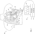
- Fig. 1 is a schematic, pictorial illustration of a system 20 for monitoring the function of a heart 22, in accordance with an embodiment of the present invention.
- Multiple antennas 24, 26, 28, 30, 32 are disposed at different, respective locations around a thorax 34 of the patient.
- the thorax is transparent in the figure so as to make visible heart 22 and lungs 36, as well as antennas 28 and 30 on the patient's side and back.
- the antennas in this embodiment partially surround the thorax.
- a larger number of antennas may surround the thorax completely.
- a smaller number of antennas possibly only one or two antennas, may be used.
- the use of three or more antennas is advantageous in providing multi-dimensional heart motion data, as explained further hereinbelow.
- antennas 24, 26, 28, 30, 32 are fixed to the skin of the torso.
- the antennas may have the form of adhesive patches, as described in greater detail with reference to Fig. 4 , for example.
- a dielectric gel may be spread between the front surfaces of the antennas and the skin, as described, for example, in the above-mentioned PCT/IB2009/055438. This gel may have a high dielectric constant at microwave frequencies, to give good RF impedance matching, and high conductivity at low frequencies to enhance electrocardiogram signal acquisition.
- the antennas may be attached to and held in place by a suitable garment, such as a vest (not shown), which the patient wears during the monitoring procedure.
- a suitable garment such as a vest (not shown)
- the procedure takes a short time, on the order of a few hours or less, although it is possible to monitor patients in this manner over the course of a day or even several days.
- Antennas 24, 26, 28, 30, 32 are connected by cables 38 to a control console 40.
- the console comprises a front end 42, which drives the antennas to direct RF electromagnetic waves from different, respective directions toward heart 22. In response to the waves that are scattered from the heart (and from other features in the body), the antennas output RF signals.
- Front end 42 receives these signals via cables 38, filters and digitizes the signals, and passes the resulting digital samples to processing circuitry 44.
- This processing circuitry 44 processes the RF signals over time so as to provide a multi-dimensional measurement of movement of the heart, as shown and described below.
- processing circuitry 44 comprises a general-purpose computer processor, which is programmed in software to carry out the functions described herein. Additionally or alternatively, processing circuitry 44 may comprise dedicated or programmable hardware logic circuits.
- processing circuitry 44 drives a display 46 to show a measurement of the movement of the heart, either graphically or numerically, or both. Additionally or alternatively, the processing circuitry may make other measurements based on the RF signals, such as measuring the amount of fluid accumulated in lungs 36, as described in greater detail hereinbelow. Further additionally or alternatively, front end 42 may receive ECG signals from the antennas on the body surface, and processor 44 may process and output ECG information in addition to measurement of heart motion. The combination of ECG and motion measurement in a single unit is efficient and useful in providing a complete picture of heart function, both electrical and mechanical.
- antennas 24 and 30 are shown in the figure as comprising position sensors 48. (The other antennas may also comprise position sensors, but these sensors are omitted from the figures for the sake of simplicity.)
- position sensors 48 may also comprise position sensors, but these sensors are omitted from the figures for the sake of simplicity.
- Various types of position sensors that are known in the art, such as magnetic, ultrasonic, optical or even mechanical position sensors, may be used for this purpose.
- PCT/IB2009/055438 includes further details of such position sensors and their integration in a radar-based measurement system.
- Fig. 2 is a schematic representation of the screen of display 46 in system 20, in accordance with an embodiment of the present invention.
- the display is configurable by the user to show different measurements in various different formats.
- display 46 shows traces 50 that are indicative of the motion of selected points on the heart wall over time, as measured by system 20.
- An ECG trace 52 is displayed alongside the wall motion traces for comparison. (Although only two motion traces and one ECG trace are shown in Fig. 2 for the sake of simplicity, a larger number of traces may alternatively be displayed.)
- a graphical window 54 gives a two-dimensional (2D) view of the measured heart motion and also enables the user to choose the points whose motion is to be shown by traces 50. Alternatively, given a sufficient number of measurement points around the heart, window 54 may show a real-time three-dimensional (3D) representation of heart wall motion.
- Display 46 may optionally include other information and user interface features.
- a parameter window 56 may show parameters derived from the measurements made by system 20, such as cardiovascular and/or respiratory parameters, in either graphical or numerical form (or both).
- a status window 58 shows the current status of each of the antennas. This window may indicate, for example, an antenna that is not properly attached to the body (based on measurement of impedance between the antenna and the skin or on characteristics of the RF signals from the antenna), so that the operator can correct the situation.
- a control window 60 displays status messages and operational buttons to turn system functions on and off.
- Fig. 3 is a block diagram that schematically shows functional elements of system 20, and specifically of front end 42, in accordance with an embodiment of the present invention.
- the elements of the front end exchange data and control instructions via a high-speed bus 62, which is connected to processing circuitry 44 via a bridge 64.
- antennas 24, 26, 28, 30, 32 are connected via cables 38 and a switching matrix 78 to a diplexer 66 at the input to front end 42.
- the diplexer separates out the low-frequency ECG signals from the RF signals, passing the ECG signals to an ECG preprocessing circuit 68. This circuit filters and digitizes the ECG signals and passes the ECG data via bus 62 to processing circuitry 44.
- Front end 42 comprises a RF generator 70, which serves as a driver circuit to generate signals at multiple different frequencies for exciting the transmitting antennas.
- a RF digitizer 72 demodulates and digitizes the signals received by the receiving antennas. Typically, the signals are in the range of about 400 MHz to about 4 GHz, although higher and lower frequencies outside this range may also be used.
- An I/Q cancellation unit 74 performs signal conditioning functions, including amplification of the outgoing and the incoming signals and cancellation of background components in the received signals. The background cancellation functions of unit 74 are controlled by an I/Q controller 76, as is described in greater detail hereinbelow.
- Switching matrix 78 selects different sets of the antennas to transmit and receive signals at different, respective times and frequencies, in a predetermined temporal pattern.
- the sets comprise pairs of antennas - one transmitting and one receiving.
- the switching matrix may select a set consisting of a single monostatic antenna, which both transmits and receives. Further alternatively, other antenna groupings may also be used.
- the structure and operation of a switching matrix of this sort are described in detail in PCT/IB2009/055438.
- Switching matrix 78 and RF generator 70 together serve as excitation circuitry and generate a temporal excitation pattern comprising a sequence of measurement frames, wherein each frame typically defines a sweep of the excitation signal both in frequency and over spatial channels (antennas or antenna pairs). The beginning of each frame is triggered by a trigger controller 80, which also provides a clock input to the other components of front end 42.
- the sweep over multiple different frequencies creates, in effect, an ultra-wideband signal, which is equivalent, in the signal processing domain, to a very short radar pulse.
- the use of this sort of ultra-wideband signal enables system 20 to measure path length and heart wall range more accurately and robustly than can generally be achieved using narrowband methods that are known in the art.
- system 20 is shown and described as comprising multiple antennas at different locations on the patient's thorax, the ultra-wideband approach described here may alternatively be used advantageously in measurements of heart wall movement using only a single antenna.
- I/Q cancellation unit 74 modifies the phase and amplitude of the sampled signals from RF digitizer 72, under the control of I/Q controller 76, so as to generate an anti-phased signal matching a background component that is to be canceled.
- This background component may, for example, be a constant and/or slowly-varying part of the incoming signals, which is canceled in order to enhance the time-varying signal component that is due to heart motion.
- the I/Q cancellation unit generates a signal that is equal in amplitude to the background component but 180 O out of phase and adds this anti-phased signal to the received signal from switching matrix 78 and digitizer 72. The I/Q cancellation unit thus cancels the background component without degrading the actual radar signal from the body.
- Processing circuitry 44 collects samples of the received signals, following background cancellation, and processes the samples to identify and locate reflecting volumes within the thorax that correspond to points on the heart surface.
- One method that may be used for this purpose is the inverse spherical Radon transform. More specifically, PCT/IB2009/055438 describes a first-order approximation of the inverse spherical Radon transform, which can be applied efficiently and effectively to the sampled RF signals.
- processing circuitry 44 may apply other transform techniques. For example, the processing circuitry may compute a frequency response vector for each pair of antennas, and may then apply a window function, such as a Kaiser window, to each vector and transform the windowed frequency data to the time domain using an inverse Fast Fourier Transform (FFT). A time-domain filter, such as a Kalman filter, may be applied to the transformed data in order to model the location and motion of the heart wall. The processing circuitry may correlate location and motion data between different antenna pairs, as well as correlating the motion with ECG measurements. Additionally or alternatively, circuitry 44 may perform ECG-gated or ECG-phased background subtraction, wherein the subtracted background signal is computed as a combination of the different phases in the heartbeat.
- a window function such as a Kaiser window
- FFT inverse Fast Fourier Transform
- a time-domain filter such as a Kalman filter
- circuitry 44 may perform ECG-gated or ECG-phased background subtraction, wherein the subtracted background signal is computed as
- circuitry 44 may treat the returned signal as a superposition of a number of point reflectors, each moving and scintillating at a predefined rate and in a predefined manner.
- the locations of the point reflectors are estimated using optimization techniques, such as a modified simplex technique.
- the estimated locations are then used to calculate path length and amplitude and thereby to calculate heart wall movement and/or liquid content of the lungs.
- processing circuitry 44 may receive and process other physiological parameters in conjunction with the RF signals.
- the processing circuitry may receive breathing information, as well as data concerning patient posture, patient weight, and blood pressure.
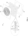
- Fig. 4 is a schematic exploded view of a patch antenna unit 82, in accordance with an embodiment of the present invention.
- the pictured antenna design may be used, for example, for any or all of the antennas shown in Fig. 1 , as well as the antennas in the figures that follow.
- This design is suitable for production as a flexible patch, similar to a large ECG electrode, which can be glued onto the body surface with a suitable adhesive.
- Antenna unit 82 is shown solely by way of example, however, and other types of antennas may similarly be used in system 20, as well as in the embodiments that are described below.
- Antenna unit 82 comprises a front surface 84 in the form of a planar printed circuit board (PCB), on which a conductive spiral 86 is printed to serve as the radiating element of the antenna, using methods of printed circuit fabrication that are known in the art.
- the front surface is made of suitable biocompatible materials in order to be brought into contact with the body surface. (A layer of gel may be applied between front surface 84 and the body surface, as explained above.)
- Element 88 comprises a ground plane 90 and a periodic structure that create an electromagnetic band gap (EBG) between the ground plane and the front surface.
- ESG electromagnetic band gap
- the EBG structure in antenna unit 82 is made up of a periodic mesh of conductive patches 92, which are connected to ground plane 90 by vias 94 through a thin dielectric layer (omitted from the figure for visual clarity).
- the periodic mesh of rear element 88 can have Cartesian or cylindrical symmetry. Since different frequencies exhibit different power densities at different locations on the rear element surface, the components of the EBG structure can have variable dimension to reflect the different frequencies accordingly.
- the PCB making up front surface 84 may be 1.6 mm thick, for example, while patches 92 are spaced 1.6 mm from ground plane 90 and contact the rear side of the front surface PCB when assembled.
- the thickness of front surface 84 and the height of the EBG can be optimized for the target VSWR performance, front lobe pattern and gain.
- the mesh of patches 92 creates an array of cavities having a parallel resonant response that mimics a perfect magnetic conductor in the specified frequency range.
- the EBG structure thus reflects the backward wave from spiral 86 in phase with the forward beam, thereby constructively adding to the main forward beam from the antenna.
- a flexible backing 96 covers the rear side of rear element 88.
- Backing 96 extends over the edges of the front surface and rear element in order to facilitate secure attachment of antenna unit 82 to the body surface.
- backing 96 may comprise an adhesive margin 98.
- Backing 96 may comprise a conductive element for receiving ECG signals from the body surface.
- front surface 84 may contain such a conductive element (not shown) alongside spiral 86, or the conductive spiral itself may serve to pick up the ECG signals.
- the antenna can be coated with metal and electrolytes to enable ECG measurement without affecting RF performance.
- a RF connector 100 connects antenna unit 82 to cable 38. This connector conveys the RF excitation signal to spiral 86 and returns both RF and ECG signals from the antenna unit to the cable.
- antennas 24, 26, 28, 30 and 32 are positioned in such a way that the RF waves they emit and/or receive pass through one of lungs 36.
- antenna 26 when antenna 26 operates in monostatic mode, it directs RF waves through the left lung toward heart 24 and then receives reflected waves from the heart back through the left lung.
- antenna 30 receives RF waves emitted by antenna 24 after transmission through the lung.
- the RF path length in either case will vary over the respiration cycle, as the lung fills with air and then empties, and it will vary depending on the amount of fluid accumulated in the lung.
- Processing circuitry 44 may analyze these path length variations in order to assess the amount of fluid accumulation in the lung.
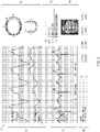
- Figs. 5A and 5B are schematic plots of propagation delay and amplitude, respectively, of RF waves reflected from the heart, in accordance with an embodiment of the present invention. These plots represent measurements made on a healthy subject using an antenna configured and positioned similarly to antenna 26. The scales are arbitrary. The delay and, to a lesser extent, the amplitude vary periodically with the heart cycle, as shown particularly by the sharp peaks in Fig. 5A .
- processing circuitry 44 may, for example, compare the delay and possibly the amplitude of the reflected waves to benchmarks provided by healthy and edematous lungs, or to previous measurements made on the same patient. Additionally or alternatively, the processing circuitry may assess the amount of fluid in the lungs by analyzing the changes in delay and/or amplitude of the reflected waves over the course of one or more respiratory cycles.
- the actual physical distance traversed by the RF waves passing through the lung may be measured, and a relation (such as a ratio) may be computed between the effective RF path length and the physical distance.
- a relation such as a ratio
- the physical distance between these antennas may also be measured.
- One way to measure the physical distance is by mechanical measurement, using a large caliper, for example.
- position sensors 48 attached to the antennas may be used to compute the spatial coordinates of each antenna, and the physical distance may then be computed simply as the Cartesian distance between the coordinate points.
- Fig. 6 is a schematic, pictorial illustration showing elements of a system 110 for diagnosis of pulmonary edema, in accordance with an embodiment of the present invention.
- antenna 26 is operated monostatically to measure the effective path length of RF waves that are reflected from heart 22 via lung 36.
- An ultrasound transducer 112 alongside antenna 26 is used to measure the physical distance to the heart and back. (Although antenna 26 and transducer 112 are shown, for the sake of clarity, as separate units, they may alternatively be integrated in a single package.)
- the heart wall is identified in both the RF and ultrasound data as the nearest significantly moving reflective surface.
- Processing circuitry 44 computes the relation between the physical distance traversed by the ultrasonic waves and the effective path length traversed by the RF waves. Variations in this relation among different patients and among measurements at different points in time for a given patient are indicative of the amount of fluid in the lung.
- Fig. 7 is a schematic, pictorial illustration showing elements of a system 120 for pacing heart 22 based on measurements of heart wall motion, in accordance with an embodiment of the present invention.
- this figure shows a single antenna 26 used to measure motion of heart 22, but alternatively, multiple antennas may be used (as shown in Fig. 1 , for example) to provide multi-dimensional wall motion data.
- a pacing circuit 122 receives and processes the RF signals from the antennas in order to measure the heart wall movement. Based on this measurement, the pacing circuit generates pacing signals to drive pacing electrodes 124 in the heart.
- the pacing circuit may adjust the timing and/or amplitude of the pacing signals adaptively, while measuring the wall movement, in order to reach an optimal therapeutic result.
- antenna 26 may also be used in assessing the fluid content of the lungs. The level of fluid content may then be used in adjusting the pacing regime of electrodes 124, as described, for example, in U.S. Patent 7,191000 .
- Fig. 8 is a block diagram that schematically illustrates a patch antenna unit 130, in accordance with the present invention.
- Patch 130 in effect, performs most of the functions of system 20, using components that are contained inside an integrated package 142 having the form of a patch, which is typically no more than 20 x 50 mm across (and may be smaller).
- package 142 may include an adhesive layer (as shown in Fig. 4 , for example), by means of which unit 130 can be affixed to the patient's skin.
- Patch unit 130 comprises a flat antenna 132, which may be of one of the types described above.
- a transceiver 136 generates driving signals for transmission by antenna 132 and filters and digitizes the reflected signals that the antenna receives from the patient's body.
- An active background cancellation circuit 134 cancels background components from the reflected signals, in a manner similar to that of I/Q cancellation unit 74, shown in Fig. 3 .
- a processor 138 controls the operation of the other components of patch 130 and processes the digitized signals output by transceiver 136 in order to extract heart wall motion data, in a similar manner to processing circuitry 44.
- a power module 144 such as a low-profile battery, provides power to the components of the patch unit.
- Patch unit 130 also comprises an ECG electrode 140, in electrical contact with the patient's skin, and an ECG acquisition circuit 150, which filters and digitizes the ECG signals for input to processor 138.
- Patch unit 130 may comprise a user interface, such as one or more indicator LEDs 146, which signal the operational state of the patch (on/off, and possibly parameters such as battery level, quality of skin contact or signal strength).
- the user interface may comprise a more informative display, such as a LCD, as well as user controls, such as on/off and adjustment buttons.
- a communication interface 148 communicates with a remote console (not shown), in order to transmit radar and ECG measurement data and possibly to receive operational commands.
- the communication interface typically comprises a wireless link, such as a Bluetooth TM or WiFi link.
- the console may be located in proximity to the patient's location and may thus receive data from interface 148 directly.
- interface 148 may communicate with a local gateway, such as a personal computer or smart phone, which communicates with the console over a network, such as the Internet or a telephone network.
- the console may comprise a server, which stores the data for subsequent viewing and analysis by a physician or other expert. This sort of system configuration is particularly useful for extended ambulatory monitoring.
Landscapes
- Health & Medical Sciences (AREA)
- Life Sciences & Earth Sciences (AREA)
- Heart & Thoracic Surgery (AREA)
- Engineering & Computer Science (AREA)
- General Health & Medical Sciences (AREA)
- Biophysics (AREA)
- Biomedical Technology (AREA)
- Veterinary Medicine (AREA)
- Public Health (AREA)
- Animal Behavior & Ethology (AREA)
- Cardiology (AREA)
- Physics & Mathematics (AREA)
- Pathology (AREA)
- Surgery (AREA)
- Molecular Biology (AREA)
- Medical Informatics (AREA)
- Radiology & Medical Imaging (AREA)
- Nuclear Medicine, Radiotherapy & Molecular Imaging (AREA)
- Physiology (AREA)
- Hematology (AREA)
- Measurement And Recording Of Electrical Phenomena And Electrical Characteristics Of The Living Body (AREA)
- Measuring Pulse, Heart Rate, Blood Pressure Or Blood Flow (AREA)
- Pulmonology (AREA)
- Oral & Maxillofacial Surgery (AREA)
- Dentistry (AREA)
- Measurement Of The Respiration, Hearing Ability, Form, And Blood Characteristics Of Living Organisms (AREA)
- Artificial Intelligence (AREA)
- Signal Processing (AREA)
- Psychiatry (AREA)
- Computer Vision & Pattern Recognition (AREA)
- Mathematical Physics (AREA)
- Measuring And Recording Apparatus For Diagnosis (AREA)
- Vascular Medicine (AREA)
Description
- The present invention relates generally to systems for medical diagnostic measurement and monitoring, and specifically to radio frequency (RF)-based measurement and monitoring of the heart.
- RF imaging is best known in the context of radar systems, but RF diagnostic imaging and measurement systems have also been developed for medical applications. For example,
U.S. Patent Application Publication 2008/0169961 , describes computerized tomography using radar, which may be used for generating an image of living tissue. - As another example,
U.S. Patent Application Publication 2009/0299175 , describes a method and apparatus for determining and tracking the location of a metallic object in a living body, using a radar detector adapted to operate on a living body. Applications described in this publication include determination of the extent of in-stent restenosis, performing therapeutic thrombolysis, and determining operational features of a metallic implant. - Yet another example is
U.S. Patent 5,766,208 , which describes a non-acoustic pulse-echo radar monitor, which is employed in the repetitive mode, whereby a large number of reflected pulses are averaged to produce a voltage that modulates an audio oscillator to produce a tone that corresponds to the heart motion. The monitor output potential can be separated into a cardiac output indicative of the physical movement of the heart, and a pulmonary output indicative of the physical movement of the lung. -
U.S. Patent 4,926,868 , describes a method and apparatus for cardiac hemodynamic monitoring based on the complex field amplitudes of microwaves propagated through and scattered by thoracic cardiovascular structures, particularly the heart chambers, as a function of time during the cardiac cycle. The apparatus uses conformal microstrip antennas that operate in the UHF band. The basic measurement technique is vector network analysis of the power wave scattering parameter. -
U.S. Patent Application Publication 2009/0240133 , describes a radio apparatus and method for non-invasive, thoracic radio interrogation of a subject for the collection of hemodynamic, respiratory and/or other cardiopulmonary related data. A radio transmitter transmits an unmodulated radio interrogation signal from an antenna into a subject, and a radio receiver captures, through the antenna, reflections of the transmitted radio interrogation signal returned from the subject. A Doppler component of the reflections contains the data that can be extracted from the captured reflections. -
WO 2009/031149 discloses a wearable monitoring apparatus for monitoring at least one biological parameter of an internal tissue of an ambulatory user. - In
US 2008/224,688 , a method of determining the condition of a bulk tissue sample, is described. - Lin J C at al, "Microwave Imaging of Cerebral EDEMA", Proceedings of the IEEE, vol. 70, no.5, 1 May 1982 (1982-05-01), page 523/524, discloses a microwave-transmission technique for detection and monitoring of cerebral edema.
- In Guido Biffi Gentili et al, "A Versatile Microwave Plethysmograph for the Monitoring of Physiological Parameters". IEEE Transactions on Biomedical Engineering, IEEE Service Center, Pistataway, vol. 49, no. 10, 1 October 2002 a simple microwave technique for in vivo monitoring of human pulmonary and cardiac activity is presented.
- In Pedersen P C et al, "Microwave Reflection and Transmission Measurements for Pulmonary Diagnosis and Monitoring", IEEE Tranasctions on Biomedical Engineering, IEEE Service Center, Piscataway, vol. BME-19, no. 1, 1 January 1978, pages 40-48, the potential of using low intensity penetrating microwave energy in diagnosis and monitoring of pulmonary diseases such as edema and emphysema is investigated.
- There is provided, in accordance with an embodiment of the present invention, a diagnostic apparatus as defined by
claim 1. Optional features are defined by the dependent claims. - The processing circuitry may be configured to measure a change in the path characteristic over one or more respiratory cycles of the lung, and to assess the fluid content responsively to the change.
- The path characteristic includes an effective RF path length of the RF electromagnetic waves through the body. In some embodiments, the processing circuitry is configured to receive a measure of a physical distance traversed by the RF electromagnetic waves through the thorax, and to compare the effective RF path length to the physical distance in order to assess the amount of the fluid accumulation. In one embodiment, the one or more antennas include a transmitting antenna at a first location on a first side of the thorax, which transmits the RF electromagnetic waves through the lung, and a receiving antenna, which receives the waves that have passed through the lung at a second location on a second side of the thorax, opposite the first side, and the physical distance is measured between the first and second locations.
- Alternatively, the one or more antennas include at least one antenna that is configured to direct the RF electromagnetic waves through the lung toward a heart in the body, and to output the RF signals responsively to the RF electromagnetic waves reflected from the heart. The apparatus may include an ultrasonic transducer, which is adjacent to the at least one antenna and is configured to direct ultrasonic waves toward the heart and receive the ultrasonic waves reflected from the heart so as to provide a measure of the physical distance.
- Additionally or alternatively, the path characteristic includes an amplitude of the RF signals.
- The present invention will be more fully understood from the following detailed description of the embodiments thereof, taken together with the drawings in which:
-
-
Fig. 1 is a schematic, pictorial illustration showing a system for monitoring of heart function, in accordance with an embodiment of the present invention; -
Fig. 2 is a schematic representation of a display screen in a system for monitoring of heart function, in accordance with an embodiment of the present invention; -
Fig. 3 is a block diagram that schematically shows functional elements of a system for monitoring of heart function, in accordance with an embodiment of the present invention; -
Fig. 4 is a schematic exploded view of a patch antenna, in accordance with an embodiment of the present invention; -
Figs. 5A and 5B are schematic plots of propagation delay and amplitude, respectively, of RF waves reflected from the heart, in accordance with an embodiment of the present invention; -
Fig. 6 is a schematic, pictorial illustration showing elements of a system for diagnosis of pulmonary edema, in accordance with an embodiment of the present invention; -
Fig. 7 is a schematic, pictorial illustration showing elements of a system for pacing the heart, in accordance with an embodiment of the present invention; and -
Fig. 8 is a block diagram that schematically illustrates a patch antenna unit, in accordance with another embodiment of the present invention. - PCT Patent Application
PCT/IB2009/055438 , describes the use of radar imaging techniques to identify and locate features in the body, based on the difference in their complex dielectric constant relative to the dielectric constant of the surrounding tissue. In the disclosed embodiments, an array of antennas (also referred to as antenna elements) directs RF electromagnetic waves toward the heart and receives the waves that are scattered from within the body. Excitation circuitry applies a RF excitation waveform at multiple different frequencies to different transmitting antennas in the array. Processing circuitry receives and processes signals from different receiving antenna elements in order to locate a feature or features of interest, and possibly to track the movement of such features over the course of the heart cycle. The selection of transmitting and receiving antennas, as well as the selection of excitation frequency, follows a predetermined temporal pattern, which may be implemented by a switching matrix connected to the antenna elements. - As a result of this scheme of excitation and reception, the processing circuitry receives and processes signals from multiple spatial channels (corresponding to different pairs of antennas) at multiple different frequencies for each channel. Taken together in the time domain, these multi-frequency signals are equivalent to short pulses of RF energy. To reconstruct a three-dimensional (3D) image of the interior of the body and find the location of a feature or features, the processing circuitry applies a spatial transform to the set of received signals. The transform may, for example, comprise an inverse spherical Radon transform or an algebraic approximation of such a transform.
- Embodiments of the present invention that are described hereinbelow apply techniques similar to those described in
PCT/IB2009/055438 for purposes of cardiovascular diagnosis and therapy. In one embodiment, multiple antennas are disposed at different, respective locations on the thorax of a patient, typically surrounding all or at least a part of the thorax. The antennas direct RF waves from different, respective directions toward the heart and output RF signals in response to the scattered waves that they receive. The RF signals received over time are processed so as to provide a multi-dimensional (two- or even three-dimensional) measurement of movement of the heart. This approach can give a picture of heart wall movement that resembles the sort of information provided by cardiac ultrasound imaging, but does not require the active involvement of an expert operator and can even be carried out over a long period while the patient is ambulatory. - Heart wall motion measured by embodiments of the present invention provides detailed diagnostic information regarding functioning of the heart muscle. For example, the heart motion information is useful in diagnosis and monitoring of cardiac ischemia and heart failures, and can also give an indication of cardiac performance, such as chamber volume or ejection fraction. The information provided by embodiments of the present invention can be used in diagnosis, as well as prediction, of ischemic disease and/or ischemic events, such as acute myocardial infarction. The heart wall motion may be compared before, during and after heart stress caused by physical exercise or by medication, in a manner similar to ECG-based stress testing. However, no method is falling under the scope of the appended claims.
- As yet another example, the heart wall motion information provided by embodiments of the present invention may be used in place of ultrasonic imaging data in analyzing and diagnosing cardiac mechanical function. For instance, radar-based measurements may be used instead of the Doppler imaging techniques described by Larsson et al., in "State Diagrams of the Heart - a New Approach to Describing Cardiac Mechanics," Cardiovascular Ultrasound 7:22 (2009).
- Additionally or alternatively, embodiments of the present invention can be used in long-term monitoring of heart conditions, and particularly as an ambulatory monitor for the detection of "silent ischemias" in coronary artery disease. Heart wall motion monitoring of this sort can thus be used as a diagnostic tool in addition to or instead of conventional stress testing or Holter monitoring.
- The heart motion information provided by embodiments of the present invention may also be used for therapeutic purposes. For example, in one embodiment, a pacemaker is driven to pace the heart based on this sort of measurement, as an addition to other parameters, so that the amplitude and timing of the pacing signal give an optimal result in terms of the actual profile of contraction of the heart muscle. This sort of approach can be particularly useful in cardiac resynchronization therapy.
- In some embodiments, these RF-based techniques are used to assess fluid accumulation in the lungs, typically for diagnosis and follow-up of pulmonary edema or lung congestion. In these embodiments, one or more antennas on the thorax direct RF waves through one (or both) of the lungs and output RF signals in response to the waves that have passed through the lung. The RF signals are processed over time in order to measure a path characteristic of the RF waves passing through the body, such as the effective RF path length of the RF waves. The RF path length, as opposed to the actual, physical distance, is defined by the length of time required for the waves to pass through the chest (either directly, from one side to the other, or by reflection from the heart and return to an antenna). This path length depends on the dielectric constant of the tissue along the path. When there is fluid in the lungs, the dielectric constant is greater (relative to normal, air-filled lungs), and the RF path length increases accordingly. This RF path length may thus be used to assess the fluid content of the lung.
- In some embodiments, monitoring information is sent from a local controller attached to the antennas on the patient's body to a center where is the information can be accessed by a referring physician, experts, technicians, and/or the patient himself. The data may flow via a local gateway device, such as a cell-phone or personal computer, via a network, such as the Internet or telephone network, to the center, where it is stored.
- Various types of antennas may be used in implementing examples not falling under the scope of the claims, including the sort of cavity-backed antenna that is described in PCT/IB2009/055438. Alternatively, some embodiments of the present invention use a planar antenna comprising a conductive spiral, which is formed on the front surface of the antenna. The antenna is backed by an in-phase reflective structure based on an electromagnetic band gap (EBG) structure between the antenna ground plane and the front surface. This design provides a flat, possibly flexible antenna, which can be fixed to the body surface by a gel or other adhesive. (Suitable types of gels for this purpose are described in PCT/IB2009/055438.) The antenna may also comprise a conductive element, which receives electrocardiogram (ECG) signals from the body surface along with the RF signals output by the antenna itself. The antenna thus performs two complementary measurements simultaneously and obviates the need for separate ECG electrodes.
- In one embodiment, the antenna is part of a self-contained patch that also includes radar processing circuits and a power source. The patch may also include a transmitter, such as a wireless unit, for transmission of data to a monitor or gateway.
-
Fig. 1 is a schematic, pictorial illustration of asystem 20 for monitoring the function of aheart 22, in accordance with an embodiment of the present invention.Multiple antennas thorax 34 of the patient. (The thorax is transparent in the figure so as to makevisible heart 22 andlungs 36, as well asantennas - Typically, for good RF coupling,
antennas Fig. 4 , for example. Additionally or alternatively, for improved coupling, a dielectric gel may be spread between the front surfaces of the antennas and the skin, as described, for example, in the above-mentioned PCT/IB2009/055438. This gel may have a high dielectric constant at microwave frequencies, to give good RF impedance matching, and high conductivity at low frequencies to enhance electrocardiogram signal acquisition. Further additionally or alternatively, the antennas may be attached to and held in place by a suitable garment, such as a vest (not shown), which the patient wears during the monitoring procedure. Typically, the procedure takes a short time, on the order of a few hours or less, although it is possible to monitor patients in this manner over the course of a day or even several days. -
Antennas cables 38 to acontrol console 40. The console comprises afront end 42, which drives the antennas to direct RF electromagnetic waves from different, respective directions towardheart 22. In response to the waves that are scattered from the heart (and from other features in the body), the antennas output RF signals.Front end 42 receives these signals viacables 38, filters and digitizes the signals, and passes the resulting digital samples to processingcircuitry 44. This processing circuitry processes the RF signals over time so as to provide a multi-dimensional measurement of movement of the heart, as shown and described below. Typically, processingcircuitry 44 comprises a general-purpose computer processor, which is programmed in software to carry out the functions described herein. Additionally or alternatively, processingcircuitry 44 may comprise dedicated or programmable hardware logic circuits. - In the pictured embodiment, processing
circuitry 44 drives adisplay 46 to show a measurement of the movement of the heart, either graphically or numerically, or both. Additionally or alternatively, the processing circuitry may make other measurements based on the RF signals, such as measuring the amount of fluid accumulated inlungs 36, as described in greater detail hereinbelow. Further additionally or alternatively,front end 42 may receive ECG signals from the antennas on the body surface, andprocessor 44 may process and output ECG information in addition to measurement of heart motion. The combination of ECG and motion measurement in a single unit is efficient and useful in providing a complete picture of heart function, both electrical and mechanical. - In some embodiments, it is useful to know the precise locations, and possibly also the orientations, of the antennas. For this purpose,
antennas position sensors 48. (The other antennas may also comprise position sensors, but these sensors are omitted from the figures for the sake of simplicity.) Various types of position sensors that are known in the art, such as magnetic, ultrasonic, optical or even mechanical position sensors, may be used for this purpose. PCT/IB2009/055438 includes further details of such position sensors and their integration in a radar-based measurement system. -
Fig. 2 is a schematic representation of the screen ofdisplay 46 insystem 20, in accordance with an embodiment of the present invention. Typically, the display is configurable by the user to show different measurements in various different formats. In the example shown inFig. 2 ,display 46 shows traces 50 that are indicative of the motion of selected points on the heart wall over time, as measured bysystem 20. AnECG trace 52 is displayed alongside the wall motion traces for comparison. (Although only two motion traces and one ECG trace are shown inFig. 2 for the sake of simplicity, a larger number of traces may alternatively be displayed.) - A
graphical window 54 gives a two-dimensional (2D) view of the measured heart motion and also enables the user to choose the points whose motion is to be shown by traces 50. Alternatively, given a sufficient number of measurement points around the heart,window 54 may show a real-time three-dimensional (3D) representation of heart wall motion. -
Display 46 may optionally include other information and user interface features. For example, aparameter window 56 may show parameters derived from the measurements made bysystem 20, such as cardiovascular and/or respiratory parameters, in either graphical or numerical form (or both). Astatus window 58 shows the current status of each of the antennas. This window may indicate, for example, an antenna that is not properly attached to the body (based on measurement of impedance between the antenna and the skin or on characteristics of the RF signals from the antenna), so that the operator can correct the situation. Acontrol window 60 displays status messages and operational buttons to turn system functions on and off. -
Fig. 3 is a block diagram that schematically shows functional elements ofsystem 20, and specifically offront end 42, in accordance with an embodiment of the present invention. The elements of the front end exchange data and control instructions via a high-speed bus 62, which is connected to processingcircuitry 44 via abridge 64. To enable ECG measurements,antennas cables 38 and a switchingmatrix 78 to adiplexer 66 at the input tofront end 42. The diplexer separates out the low-frequency ECG signals from the RF signals, passing the ECG signals to anECG preprocessing circuit 68. This circuit filters and digitizes the ECG signals and passes the ECG data viabus 62 to processingcircuitry 44. -
Front end 42 comprises aRF generator 70, which serves as a driver circuit to generate signals at multiple different frequencies for exciting the transmitting antennas. ARF digitizer 72 demodulates and digitizes the signals received by the receiving antennas. Typically, the signals are in the range of about 400 MHz to about 4 GHz, although higher and lower frequencies outside this range may also be used. An I/Q cancellation unit 74 performs signal conditioning functions, including amplification of the outgoing and the incoming signals and cancellation of background components in the received signals. The background cancellation functions ofunit 74 are controlled by an I/Q controller 76, as is described in greater detail hereinbelow. -
Switching matrix 78 selects different sets of the antennas to transmit and receive signals at different, respective times and frequencies, in a predetermined temporal pattern. Typically, the sets comprise pairs of antennas - one transmitting and one receiving. Alternatively, the switching matrix may select a set consisting of a single monostatic antenna, which both transmits and receives. Further alternatively, other antenna groupings may also be used. The structure and operation of a switching matrix of this sort are described in detail in PCT/IB2009/055438.Switching matrix 78 andRF generator 70 together serve as excitation circuitry and generate a temporal excitation pattern comprising a sequence of measurement frames, wherein each frame typically defines a sweep of the excitation signal both in frequency and over spatial channels (antennas or antenna pairs). The beginning of each frame is triggered by atrigger controller 80, which also provides a clock input to the other components offront end 42. - The sweep over multiple different frequencies creates, in effect, an ultra-wideband signal, which is equivalent, in the signal processing domain, to a very short radar pulse. The use of this sort of ultra-wideband signal enables
system 20 to measure path length and heart wall range more accurately and robustly than can generally be achieved using narrowband methods that are known in the art. Althoughsystem 20 is shown and described as comprising multiple antennas at different locations on the patient's thorax, the ultra-wideband approach described here may alternatively be used advantageously in measurements of heart wall movement using only a single antenna. - The functions of I/
Q cancellation unit 74 are also described in detail in PCT/IB2009/055438. Briefly,unit 74 modifies the phase and amplitude of the sampled signals fromRF digitizer 72, under the control of I/Q controller 76, so as to generate an anti-phased signal matching a background component that is to be canceled. This background component may, for example, be a constant and/or slowly-varying part of the incoming signals, which is canceled in order to enhance the time-varying signal component that is due to heart motion. The I/Q cancellation unit generates a signal that is equal in amplitude to the background component but 180O out of phase and adds this anti-phased signal to the received signal from switchingmatrix 78 anddigitizer 72. The I/Q cancellation unit thus cancels the background component without degrading the actual radar signal from the body. -
Processing circuitry 44 collects samples of the received signals, following background cancellation, and processes the samples to identify and locate reflecting volumes within the thorax that correspond to points on the heart surface. One method that may be used for this purpose is the inverse spherical Radon transform. More specifically, PCT/IB2009/055438 describes a first-order approximation of the inverse spherical Radon transform, which can be applied efficiently and effectively to the sampled RF signals. - Alternatively, processing
circuitry 44 may apply other transform techniques. For example, the processing circuitry may compute a frequency response vector for each pair of antennas, and may then apply a window function, such as a Kaiser window, to each vector and transform the windowed frequency data to the time domain using an inverse Fast Fourier Transform (FFT). A time-domain filter, such as a Kalman filter, may be applied to the transformed data in order to model the location and motion of the heart wall. The processing circuitry may correlate location and motion data between different antenna pairs, as well as correlating the motion with ECG measurements. Additionally or alternatively,circuitry 44 may perform ECG-gated or ECG-phased background subtraction, wherein the subtracted background signal is computed as a combination of the different phases in the heartbeat. - In estimating the heart wall location,
circuitry 44 may treat the returned signal as a superposition of a number of point reflectors, each moving and scintillating at a predefined rate and in a predefined manner. The locations of the point reflectors are estimated using optimization techniques, such as a modified simplex technique. The estimated locations are then used to calculate path length and amplitude and thereby to calculate heart wall movement and/or liquid content of the lungs. - Further additionally or alternatively, processing
circuitry 44 may receive and process other physiological parameters in conjunction with the RF signals. For example, the processing circuitry may receive breathing information, as well as data concerning patient posture, patient weight, and blood pressure. -
Fig. 4 is a schematic exploded view of apatch antenna unit 82, in accordance with an embodiment of the present invention. The pictured antenna design may be used, for example, for any or all of the antennas shown inFig. 1 , as well as the antennas in the figures that follow. This design is suitable for production as a flexible patch, similar to a large ECG electrode, which can be glued onto the body surface with a suitable adhesive.Antenna unit 82 is shown solely by way of example, however, and other types of antennas may similarly be used insystem 20, as well as in the embodiments that are described below. -
Antenna unit 82 comprises afront surface 84 in the form of a planar printed circuit board (PCB), on which aconductive spiral 86 is printed to serve as the radiating element of the antenna, using methods of printed circuit fabrication that are known in the art. The front surface is made of suitable biocompatible materials in order to be brought into contact with the body surface. (A layer of gel may be applied betweenfront surface 84 and the body surface, as explained above.) Arear element 88 of the antenna, behind the front surface, serves as a reflective structure.Element 88 comprises aground plane 90 and a periodic structure that create an electromagnetic band gap (EBG) between the ground plane and the front surface. Details of the theory and design of this sort of antenna are provided by Bell et al., in "A Low-Profile Archimedean Spiral Antenna Using an EBG Ground Plane," IEEE Antennas and ). - The EBG structure in
antenna unit 82 is made up of a periodic mesh ofconductive patches 92, which are connected to groundplane 90 byvias 94 through a thin dielectric layer (omitted from the figure for visual clarity). The periodic mesh ofrear element 88 can have Cartesian or cylindrical symmetry. Since different frequencies exhibit different power densities at different locations on the rear element surface, the components of the EBG structure can have variable dimension to reflect the different frequencies accordingly. For the frequency range mentioned above (400 MHz to 4 GHz), the PCB making upfront surface 84 may be 1.6 mm thick, for example, whilepatches 92 are spaced 1.6 mm fromground plane 90 and contact the rear side of the front surface PCB when assembled. The thickness offront surface 84 and the height of the EBG (as defined by vias 94) can be optimized for the target VSWR performance, front lobe pattern and gain. Under these conditions, the mesh ofpatches 92 creates an array of cavities having a parallel resonant response that mimics a perfect magnetic conductor in the specified frequency range. The EBG structure thus reflects the backward wave fromspiral 86 in phase with the forward beam, thereby constructively adding to the main forward beam from the antenna. - A
flexible backing 96 covers the rear side ofrear element 88.Backing 96 extends over the edges of the front surface and rear element in order to facilitate secure attachment ofantenna unit 82 to the body surface. For this purpose, backing 96 may comprise anadhesive margin 98.Backing 96 may comprise a conductive element for receiving ECG signals from the body surface. Alternatively,front surface 84 may contain such a conductive element (not shown) alongsidespiral 86, or the conductive spiral itself may serve to pick up the ECG signals. Additionally or alternatively, the antenna can be coated with metal and electrolytes to enable ECG measurement without affecting RF performance. ARF connector 100 connectsantenna unit 82 tocable 38. This connector conveys the RF excitation signal to spiral 86 and returns both RF and ECG signals from the antenna unit to the cable. - Referring back to
Fig. 1 , some ofantennas lungs 36. For example, whenantenna 26 operates in monostatic mode, it directs RF waves through the left lung towardheart 24 and then receives reflected waves from the heart back through the left lung. As another example, in bistatic mode,antenna 30 receives RF waves emitted byantenna 24 after transmission through the lung. The RF path length in either case will vary over the respiration cycle, as the lung fills with air and then empties, and it will vary depending on the amount of fluid accumulated in the lung.Processing circuitry 44 may analyze these path length variations in order to assess the amount of fluid accumulation in the lung. -
Figs. 5A and 5B are schematic plots of propagation delay and amplitude, respectively, of RF waves reflected from the heart, in accordance with an embodiment of the present invention. These plots represent measurements made on a healthy subject using an antenna configured and positioned similarly toantenna 26. The scales are arbitrary. The delay and, to a lesser extent, the amplitude vary periodically with the heart cycle, as shown particularly by the sharp peaks inFig. 5A . - The depressed portions of both plots between
marks 260 and 290 on the horizontal scale correspond to a period of inhalation during the respiratory cycle. This depression inFig. 5A shows that when the lungs are full of air, the effective RF path length through the lung decreases, since the physical distance betweenantenna 24 andheart 22 remains about the same, while the average dielectric constant along the path decreases. Exhalation empties the lungs of air and thus increases the effective RF path length. The amplitude of the reflected wave inFig. 5B also drops during inhalation, presumably because of increased variations of the dielectric constant, and hence more reflections, along the RF path through the lung when the lung is filled with air. - For a lung with a high fluid content, the average dielectric constant will typically be higher than a healthy lung, and the path delay of RF waves traversing the lung will therefore be greater. The overall amplitude may also be greater due to reduced reflections as the waves traverse the lungs. On the other hand, the difference between air-filled and empty lungs over the respiratory cycle is expected to be smaller in both delay and amplitude than the differences shown in
Figs. 5A and 5B . Thus, to diagnose and monitor pulmonary edema, processingcircuitry 44 may, for example, compare the delay and possibly the amplitude of the reflected waves to benchmarks provided by healthy and edematous lungs, or to previous measurements made on the same patient. Additionally or alternatively, the processing circuitry may assess the amount of fluid in the lungs by analyzing the changes in delay and/or amplitude of the reflected waves over the course of one or more respiratory cycles. - In order to quantify the assessment of fluid accumulation, the actual physical distance traversed by the RF waves passing through the lung may be measured, and a relation (such as a ratio) may be computed between the effective RF path length and the physical distance. For example, referring back to
Fig. 1 , ifantennas lung 36, the physical distance between these antennas may also be measured. One way to measure the physical distance is by mechanical measurement, using a large caliper, for example. Alternatively or additionally,position sensors 48 attached to the antennas may be used to compute the spatial coordinates of each antenna, and the physical distance may then be computed simply as the Cartesian distance between the coordinate points. -
Fig. 6 is a schematic, pictorial illustration showing elements of asystem 110 for diagnosis of pulmonary edema, in accordance with an embodiment of the present invention. In this embodiment,antenna 26 is operated monostatically to measure the effective path length of RF waves that are reflected fromheart 22 vialung 36. Anultrasound transducer 112 alongsideantenna 26 is used to measure the physical distance to the heart and back. (Althoughantenna 26 andtransducer 112 are shown, for the sake of clarity, as separate units, they may alternatively be integrated in a single package.) The heart wall is identified in both the RF and ultrasound data as the nearest significantly moving reflective surface. -
Processing circuitry 44 computes the relation between the physical distance traversed by the ultrasonic waves and the effective path length traversed by the RF waves. Variations in this relation among different patients and among measurements at different points in time for a given patient are indicative of the amount of fluid in the lung. - Mechanical sensing of cardiac activity has been proposed for use in cardiac stimulation therapy, such as optimizing timing intervals during cardiac pacing. Detection of peak endocardial wall motion in the apex of the right ventricle for optimizing AV intervals has been validated clinically. Systems and methods for using cardiac wall motion sensor signals to provide hemodynamically-optimal values for heart rate and AV interval have been described, for example, in
U.S. Patent 5,549,650 , A cardiac stimulating system designed to automatically optimize both the pacing mode and one or more pacing cycle parameters in a way that results in optimization of a cardiac performance parameter, such as heart accelerations, is generally described inU.S. Patent 5,540 727 . -
Fig. 7 is a schematic, pictorial illustration showing elements of asystem 120 for pacingheart 22 based on measurements of heart wall motion, in accordance with an embodiment of the present invention. For the sake of simplicity, this figure shows asingle antenna 26 used to measure motion ofheart 22, but alternatively, multiple antennas may be used (as shown inFig. 1 , for example) to provide multi-dimensional wall motion data. Apacing circuit 122 receives and processes the RF signals from the antennas in order to measure the heart wall movement. Based on this measurement, the pacing circuit generates pacing signals to drive pacing electrodes 124 in the heart. The pacing circuit may adjust the timing and/or amplitude of the pacing signals adaptively, while measuring the wall movement, in order to reach an optimal therapeutic result. - As noted above,
antenna 26 may also be used in assessing the fluid content of the lungs. The level of fluid content may then be used in adjusting the pacing regime of electrodes 124, as described, for example, inU.S. Patent 7,191000 . -
Fig. 8 is a block diagram that schematically illustrates apatch antenna unit 130, in accordance with the present invention.Patch 130, in effect, performs most of the functions ofsystem 20, using components that are contained inside anintegrated package 142 having the form of a patch, which is typically no more than 20 x 50 mm across (and may be smaller). As in the preceding embodiments,package 142 may include an adhesive layer (as shown inFig. 4 , for example), by means of whichunit 130 can be affixed to the patient's skin. -
Patch unit 130 comprises aflat antenna 132, which may be of one of the types described above. Atransceiver 136 generates driving signals for transmission byantenna 132 and filters and digitizes the reflected signals that the antenna receives from the patient's body. An activebackground cancellation circuit 134 cancels background components from the reflected signals, in a manner similar to that of I/Q cancellation unit 74, shown inFig. 3 . Aprocessor 138 controls the operation of the other components ofpatch 130 and processes the digitized signals output bytransceiver 136 in order to extract heart wall motion data, in a similar manner to processingcircuitry 44. Apower module 144, such as a low-profile battery, provides power to the components of the patch unit. -
Patch unit 130 also comprises anECG electrode 140, in electrical contact with the patient's skin, and anECG acquisition circuit 150, which filters and digitizes the ECG signals for input toprocessor 138. -
Patch unit 130 may comprise a user interface, such as one ormore indicator LEDs 146, which signal the operational state of the patch (on/off, and possibly parameters such as battery level, quality of skin contact or signal strength). Alternatively or additionally, the user interface may comprise a more informative display, such as a LCD, as well as user controls, such as on/off and adjustment buttons. - A
communication interface 148 communicates with a remote console (not shown), in order to transmit radar and ECG measurement data and possibly to receive operational commands. The communication interface typically comprises a wireless link, such as a Bluetooth™ or WiFi link. The console may be located in proximity to the patient's location and may thus receive data frominterface 148 directly. Alternatively,interface 148 may communicate with a local gateway, such as a personal computer or smart phone, which communicates with the console over a network, such as the Internet or a telephone network. In this sort of embodiment, for example, the console may comprise a server, which stores the data for subsequent viewing and analysis by a physician or other expert. This sort of system configuration is particularly useful for extended ambulatory monitoring. - The invention is only defined by the appended claims.
Claims (13)
- A diagnostic apparatus, comprising:
a patch unit (130) with integrated package (142) having the form of a patch, including:an adhesive layer by means of which the patch unit (130) can be affixed to a patient's skin;an antenna (132) configured to be disposed on a thorax (34) of a living body so as to direct radio frequency (RF) electromagnetic waves through a lung (36) in the body and to output RF signals responsively to the waves that have passed through the lung (36), wherein the antenna comprises a planar antenna element printed on a front surface (86) of a planar printed circuit board and a rear element (88) behind the front surface and which is configured to serve as a reflective structure to reflect a backward wave from the planar antenna element in phase with a forward beam from the planar antenna element, the rear element (88) comprising an electromagnetic bandgap (EBG) structure made up of a periodic mesh of conductive patches (92) connected to a ground plane (90) by vias (94) through a dielectric layer;a transceiver (136) configured to generate driving signals for transmission by the antenna (132) and filters and digitizes the reflected signals that the antenna receives from the patient's body;a processor (138) which is configured to process the RF signals over time so as to measure RF path characteristic of the RF electromagnetic waves;a power module (144) configured to provide power to the components of the patch unit (130);an ECG electrode and acquisition circuit (140, 150), which filters and digitizes ECG signals for input to processor (138);a user interface; anda communication interface (148) for communication with a remote console,wherein:the path characteristic comprises an effective RF path length of the RF electromagnetic waves through the body, andbased on the path characteristic, the processor is configured to assess a fluid content of the lung (36). - The apparatus according to claim 1, wherein the processor is configured to measure a change in the path characteristic over one or more respiratory cycles of the lung.
- The apparatus according to any preceding claim, wherein the processor is configured to receive a measure of a physical distance traversed by the RF electromagnetic waves through the thorax, and to compare the effective RF path length to the physical distance in order to assess the amount of the fluid accumulation.
- The apparatus according to any preceding claim, further comprising an active background cancellation circuit (134).
- The apparatus according to claim 4, wherein the active background cancellation circuit (134) cancels background components from the reflected signals.
- The apparatus according to any preceding claim, wherein the processor (138) is configured to control the operation of the other components of the patch unit (130).
- The apparatus according to any preceding claim, wherein the processor (138) is configured to process the digitized signals output by transceiver (136) to extract heart wall motion data.
- The apparatus according to any preceding claim, wherein the user interface comprises one or more indicator LEDs (146) configured to signal the operational state of the patch.
- The apparatus according to claim 8, wherein the operational state includes at least one of on/off, battery level, quality of skin contact, and signal strength.
- The apparatus according to any preceding claim, wherein the user interface comprises an informative display, and user controls.
- The apparatus according to any preceding claim, wherein the communication interface (148) is configured to communicate with a remote console in order to transmit radar and ECG measurement data and optionally, receive operational commands.
- The apparatus of claim 11, wherein the remote console is configured to be located in proximity to a patient's location.
- The apparatus according to any preceding claim, wherein the antenna (132) is one of multiple antennas for disposal at different, respective locations around a thorax of a patient and the transceiver further comprises a RF generator (70) for generating signals at multiple different frequencies for exciting the antenna (132) and a switching matrix (78) for selecting different sets of the multiple antennas to transmit and receive signals at different, respective times and frequencies, in a predetermined temporal excitation pattern comprising a sequence of measurement frames, each frame comprising an excitation frequency selected from within a range from about 400 MHz to about 4 GHz, whereby the transceiver (136) is configured by the switching matrix (78) and RF generator (70) together to produce the RF electromagnetic waves in the temporal excitation pattern, wherein the transceiver further comprises a trigger controller (80) configured to trigger the beginning of each frame.
Applications Claiming Priority (3)
| Application Number | Priority Date | Filing Date | Title |
|---|---|---|---|
| PCT/IB2009/055438 WO2011067623A1 (en) | 2009-12-01 | 2009-12-01 | Locating features in the heart using radio frequency imaging |
| US12/759,715 US8989837B2 (en) | 2009-12-01 | 2010-04-14 | Methods and systems for determining fluid content of tissue |
| PCT/IB2010/054861 WO2011067685A1 (en) | 2009-12-01 | 2010-10-27 | Microwave monitoring of heart function |
Publications (3)
| Publication Number | Publication Date |
|---|---|
| EP2506917A1 EP2506917A1 (en) | 2012-10-10 |
| EP2506917A4 EP2506917A4 (en) | 2015-01-07 |
| EP2506917B1 true EP2506917B1 (en) | 2022-09-07 |
Family
ID=82160279
Family Applications (1)
| Application Number | Title | Priority Date | Filing Date |
|---|---|---|---|
| EP10834292.4A Active EP2506917B1 (en) | 2009-12-01 | 2010-10-27 | Microwave monitoring of heart function |
Country Status (5)
| Country | Link |
|---|---|
| US (6) | US8989837B2 (en) |
| EP (1) | EP2506917B1 (en) |
| JP (3) | JP5859975B2 (en) |
| CA (1) | CA2782632A1 (en) |
| WO (1) | WO2011067685A1 (en) |
Families Citing this family (94)
| Publication number | Priority date | Publication date | Assignee | Title |
|---|---|---|---|---|
| US7047058B1 (en) | 2001-02-06 | 2006-05-16 | Medrad, Inc. | Apparatuses, systems and methods for extravasation detection |
| US8802183B2 (en) | 2005-04-28 | 2014-08-12 | Proteus Digital Health, Inc. | Communication system with enhanced partial power source and method of manufacturing same |
| PT1889198E (en) | 2005-04-28 | 2015-03-06 | Proteus Digital Health Inc | Pharma-informatics system |
| WO2007130491A2 (en) | 2006-05-02 | 2007-11-15 | Proteus Biomedical, Inc. | Patient customized therapeutic regimens |
| SG175681A1 (en) | 2006-10-25 | 2011-11-28 | Proteus Biomedical Inc | Controlled activation ingestible identifier |
| MY165368A (en) | 2007-02-01 | 2018-03-21 | Proteus Digital Health Inc | Ingestible event marker systems |
| CA2676280C (en) | 2007-02-14 | 2018-05-22 | Proteus Biomedical, Inc. | In-body power source having high surface area electrode |
| US8540632B2 (en) | 2007-05-24 | 2013-09-24 | Proteus Digital Health, Inc. | Low profile antenna for in body device |
| US8989837B2 (en) | 2009-12-01 | 2015-03-24 | Kyma Medical Technologies Ltd. | Methods and systems for determining fluid content of tissue |
| ES2696984T3 (en) | 2008-07-08 | 2019-01-21 | Proteus Digital Health Inc | Ingestion event marker data infrastructure |
| US9659423B2 (en) | 2008-12-15 | 2017-05-23 | Proteus Digital Health, Inc. | Personal authentication apparatus system and method |
| EP2385781A4 (en) | 2009-01-06 | 2014-11-05 | Proteus Digital Health Inc | Ingestion-related biofeedback and personalized medical therapy method and system |
| EP2424427B1 (en) | 2009-04-28 | 2021-06-16 | Otsuka Pharmaceutical Co., Ltd. | Highly reliable ingestible event markers |
| TWI517050B (en) | 2009-11-04 | 2016-01-11 | 普羅托斯數位健康公司 | System for supply chain management |
| JP5975879B2 (en) | 2009-12-01 | 2016-08-23 | キマ メディカル テクノロジーズ リミテッド | Diagnostic device and system for diagnosis |
| MX2012008922A (en) | 2010-02-01 | 2012-10-05 | Proteus Digital Health Inc | Data gathering system. |
| JP6463599B2 (en) | 2010-04-07 | 2019-02-06 | プロテウス デジタル ヘルス, インコーポレイテッド | Small ingestible device |
| TWI557672B (en) | 2010-05-19 | 2016-11-11 | 波提亞斯數位康健公司 | Computer system and computer-implemented method to track medication from manufacturer to a patient, apparatus and method for confirming delivery of medication to a patient, patient interface device |
| JP6081355B2 (en) | 2010-07-21 | 2017-02-15 | キマ メディカル テクノロジーズ リミテッド | Embedded radio frequency sensor |
| JP2014504902A (en) | 2010-11-22 | 2014-02-27 | プロテウス デジタル ヘルス, インコーポレイテッド | Ingestible device with medicinal product |
| WO2015112603A1 (en) | 2014-01-21 | 2015-07-30 | Proteus Digital Health, Inc. | Masticable ingestible product and communication system therefor |
| US9756874B2 (en) | 2011-07-11 | 2017-09-12 | Proteus Digital Health, Inc. | Masticable ingestible product and communication system therefor |
| RU2014106126A (en) | 2011-07-21 | 2015-08-27 | Протеус Диджитал Хелс, Инк. | DEVICE, SYSTEM AND METHOD OF MOBILE COMMUNICATION |
| US10722136B2 (en) | 2011-09-02 | 2020-07-28 | Battelle Memorial Institute | Wireless and power-source-free extravasation and infiltration detection sensor |
| US8787526B2 (en) | 2011-09-08 | 2014-07-22 | Elwha Llc | Systems, devices, and methods including implants for managing cumulative X-ray radiation dosage including X-ray radiation direction determination devices |
| US8692206B2 (en) * | 2011-09-08 | 2014-04-08 | Elwha Llc | Systems, devices, and methods including implants for managing cumulative X-ray radiation dosage |
| US20140336515A1 (en) * | 2011-11-03 | 2014-11-13 | Albatross Breast Cancer Diagnostic Ltd | Ultra-wideband and infra-red multisensing integration |
| US9622666B2 (en) | 2011-12-14 | 2017-04-18 | California Institute Of Technology | Noninvasive systems for blood pressure measurement in arteries |
| ES2705168T3 (en) * | 2011-12-20 | 2019-03-22 | Sensible Medical Innovations Ltd | Thoracic garment to place electromagnetic transducers (EM) and methods to use such a thoracic garment |
| US9026193B2 (en) | 2011-12-22 | 2015-05-05 | California Institute Of Technology | Intrinsic frequency hemodynamic waveform analysis |
| US9713434B2 (en) * | 2012-02-11 | 2017-07-25 | Sensifree Ltd. | Microwave contactless heart rate sensor |
| CN104254273A (en) | 2012-02-15 | 2014-12-31 | 基马医疗科技有限公司 | Monitoring and diagnostic systems and methods |
| US8948859B2 (en) | 2012-06-11 | 2015-02-03 | Zoll Medical Corporation | Resuscitation enhancements |
| WO2014022584A1 (en) * | 2012-08-01 | 2014-02-06 | Niema Pahlevan | Cardiac microwave signal determination of cardiovascular diseases |
| JP2016508529A (en) | 2013-01-29 | 2016-03-22 | プロテウス デジタル ヘルス, インコーポレイテッド | Highly expandable polymer film and composition containing the same |
| EP2968909A4 (en) | 2013-03-14 | 2016-12-07 | Zoll Medical Corp | Shock determination based on prior shocks |
| WO2014197402A1 (en) | 2013-06-04 | 2014-12-11 | Proteus Digital Health, Inc. | System, apparatus and methods for data collection and assessing outcomes |
| WO2014151929A1 (en) | 2013-03-15 | 2014-09-25 | Proteus Digital Health, Inc. | Personal authentication apparatus system and method |
| US10175376B2 (en) | 2013-03-15 | 2019-01-08 | Proteus Digital Health, Inc. | Metal detector apparatus, system, and method |
| US9526438B2 (en) * | 2013-04-26 | 2016-12-27 | University Of Hawaii | Microwave stethoscope for measuring cardio-pulmonary vital signs and lung water content |
| US9796576B2 (en) | 2013-08-30 | 2017-10-24 | Proteus Digital Health, Inc. | Container with electronically controlled interlock |
| MX356850B (en) | 2013-09-20 | 2018-06-15 | Proteus Digital Health Inc | Methods, devices and systems for receiving and decoding a signal in the presence of noise using slices and warping. |
| KR102193134B1 (en) | 2013-10-14 | 2020-12-21 | 삼성전자주식회사 | Wearable body sensing device and system including the same |
| MX368824B (en) | 2013-10-18 | 2019-10-17 | California Inst Of Techn | Intrinsic frequency analysis for left ventricle ejection fraction or stroke volume determination. |
| WO2015063766A1 (en) | 2013-10-29 | 2015-05-07 | Kyma Medical Technologies Ltd. | Antenna systems and devices and methods of manufacture thereof |
| US10084880B2 (en) * | 2013-11-04 | 2018-09-25 | Proteus Digital Health, Inc. | Social media networking based on physiologic information |
| CA2931274A1 (en) | 2014-01-21 | 2015-07-30 | California Institute Of Technology | Portable electronic hemodynamic sensor systems |
| US11013420B2 (en) | 2014-02-05 | 2021-05-25 | Zoll Medical Israel Ltd. | Systems, apparatuses and methods for determining blood pressure |
| US9782093B2 (en) | 2014-03-14 | 2017-10-10 | Zoll Medical Corporation | Vector-based shock indication |
| US20150265221A1 (en) * | 2014-03-19 | 2015-09-24 | Boston Scientific Scimed, Inc. | Methods and systems for diagnostic monitoring |
| WO2015191761A1 (en) | 2014-06-10 | 2015-12-17 | Zoll Medical Corporation | Determining initial treatments from spectral data |
| JP6665171B6 (en) * | 2014-06-11 | 2020-04-08 | カーディアック モーション, エルエルシー | Portable cardiac motion monitor |
| WO2016040337A1 (en) | 2014-09-08 | 2016-03-17 | KYMA Medical Technologies, Inc. | Monitoring and diagnostics systems and methods |
| US11241187B2 (en) * | 2014-11-03 | 2022-02-08 | Qian Xia | Electromagnetic wave sensing and modulating of neuronal activities |
| WO2016108178A1 (en) * | 2015-01-02 | 2016-07-07 | Esaote Spa | Method for quantifying the elasticity of a material by ultrasounds |
| KR20160086715A (en) * | 2015-01-12 | 2016-07-20 | 삼성전자주식회사 | Wearable apparatus for measuring biological information and method for measuring biological information using the same |
| US10548485B2 (en) | 2015-01-12 | 2020-02-04 | Zoll Medical Israel Ltd. | Systems, apparatuses and methods for radio frequency-based attachment sensing |
| US10856806B2 (en) * | 2015-02-12 | 2020-12-08 | University Of Hawaii | Lung water content measurement system and calibration method |
| US11324443B2 (en) | 2015-03-26 | 2022-05-10 | Zoll Medical Corporation | Amplitude spectrum area considerations for an external medical monitoring and treatment device |
| US20160317050A1 (en) | 2015-04-28 | 2016-11-03 | Federico Perego Costa | Hemodynamic parameter (Hdp) monitoring system for diagnosis of a health condition of a patient |
| US11051543B2 (en) | 2015-07-21 | 2021-07-06 | Otsuka Pharmaceutical Co. Ltd. | Alginate on adhesive bilayer laminate film |
| KR20180105202A (en) | 2016-01-27 | 2018-09-27 | 라이프 디텍션 테크놀로지스, 인크. | Systems and methods for detecting physical changes without physical contact |
| US10631752B2 (en) | 2016-01-27 | 2020-04-28 | Life Detection Technologies, Inc. | Systems and methods for detecting physical changes without physical contact |
| JP6552148B1 (en) | 2016-07-22 | 2019-07-31 | プロテウス デジタル ヘルス, インコーポレイテッド | Electromagnetic sensing and detection of ingestible event markers |
| US10820831B2 (en) | 2016-10-26 | 2020-11-03 | Proteus Digital Health, Inc. | Methods for manufacturing capsules with ingestible event markers |
| CN108078555A (en) * | 2016-11-23 | 2018-05-29 | 南京理工大学 | A kind of vital sign remote monitoring device based on Kalman filtering and target following |
| EP3398510A1 (en) * | 2017-05-04 | 2018-11-07 | Koninklijke Philips N.V. | System and method for dynamic focusing on the heart and/or lungs by frequency tuning and analysis of impedance phase and/or magnitude variations |
| US10862198B2 (en) | 2017-03-14 | 2020-12-08 | R.A. Miller Industries, Inc. | Wideband, low profile, small area, circular polarized uhf antenna |
| EP3632383B1 (en) * | 2017-05-30 | 2022-12-14 | Kao Corporation | Care schedule proposal device |
| US11020002B2 (en) | 2017-08-10 | 2021-06-01 | Zoll Medical Israel Ltd. | Systems, devices and methods for physiological monitoring of patients |
| JP6873022B2 (en) * | 2017-10-12 | 2021-05-19 | オムロン株式会社 | Biometric information measuring device, blood pressure measuring device, device, biometric information measuring method, and blood pressure measuring method |
| KR101903296B1 (en) * | 2017-12-26 | 2018-10-02 | 서울대학교병원 | Apparatus for monitoring pulmonary edema |
| JP2021516080A (en) | 2018-03-16 | 2021-07-01 | ゾール メディカル コーポレイションZOLL Medical Corporation | Physiological condition monitoring based on biovibration and radio frequency data analysis |
| US10716949B2 (en) | 2018-03-19 | 2020-07-21 | Zoll Medical Corporation | Changing cardiac shock delivery parameters based on a transform value |
| EP3773181A4 (en) | 2018-03-30 | 2022-01-12 | Zoll Medical Israel Ltd. | Systems, devices and methods for radio frequency-based physiological monitoring of patients |
| KR20200141095A (en) * | 2018-05-08 | 2020-12-17 | 노우 랩스, 인크. | Health-related diagnostic technique using radio/microwave frequency band spectroscopy |
| CN112154570A (en) * | 2018-05-23 | 2020-12-29 | 麦德菲尔德诊断有限公司 | Scheme for microwave absorption |
| DE102018210051A1 (en) * | 2018-06-20 | 2019-12-24 | Fraunhofer-Gesellschaft zur Förderung der angewandten Forschung e.V. | Measuring device and method for determining at least one respiratory parameter |
| EP3637430B1 (en) * | 2018-10-10 | 2023-11-15 | Tata Consultancy Services Limited | Real time unobtrusive monitoring of physiological signals |
| EP3952735A4 (en) | 2019-04-10 | 2023-01-11 | Autem Medical, LLC | System for prognosticating patient outcomes and methods of using the same |
| US11523797B2 (en) * | 2019-04-16 | 2022-12-13 | Welch Allyn, Inc. | Vital sign detection and measurement |
| JP2021023491A (en) * | 2019-08-02 | 2021-02-22 | 学校法人 東洋大学 | Radio wave type moisture meter and biological information measurement device |
| KR20210024874A (en) | 2019-08-26 | 2021-03-08 | 삼성전자주식회사 | Monitoring device inserted into human body and operating method thereof |
| TWI755866B (en) * | 2019-10-09 | 2022-02-21 | 明達醫學科技股份有限公司 | Device and method for detecting coupling between physiological signals |
| CN114901129A (en) | 2019-10-29 | 2022-08-12 | 以色列佐尔医疗有限公司 | Systems, devices, and methods for cardiac diagnosis and/or monitoring |
| IT201900025204A1 (en) * | 2019-12-23 | 2021-06-23 | Praxe Srl | Optimized wireless electrocardiograph |
| JP2021159310A (en) * | 2020-03-31 | 2021-10-11 | キヤノンメディカルシステムズ株式会社 | Biological information monitoring device and magnetic resonance imaging device |
| US11764488B2 (en) | 2020-09-09 | 2023-09-19 | Know Labs, Inc. | Methods for determining variability of a state of a medium |
| US11689274B2 (en) * | 2020-09-09 | 2023-06-27 | Know Labs, Inc. | Systems for determining variability in a state of a medium |
| TWI771103B (en) * | 2021-07-14 | 2022-07-11 | 立積電子股份有限公司 | Radar apparatus and signal receiving method thereof |
| EP4151148A1 (en) * | 2021-09-17 | 2023-03-22 | UMC Utrecht Holding B.V. | System for determining a physiological parameter of a subject |
| DE102022203457A1 (en) * | 2022-04-06 | 2023-10-12 | Fraunhofer-Gesellschaft zur Förderung der angewandten Forschung eingetragener Verein | METHOD AND DEVICE FOR MEASURING A PROCESS IN AN OBJECT |
| DE102022115034A1 (en) * | 2022-06-15 | 2023-12-21 | Altavo Gmbh | MULTI-MODAL SENSOR ARRANGEMENT FOR USE CLOSE TO THE BODY |
| PL442466A1 (en) * | 2022-10-07 | 2024-04-08 | Uniwersytet Łódzki | Cardiac sensory system |
Family Cites Families (210)
| Publication number | Priority date | Publication date | Assignee | Title |
|---|---|---|---|---|
| US4240445A (en) | 1978-10-23 | 1980-12-23 | University Of Utah | Electromagnetic energy coupler/receiver apparatus and method |
| FI58719C (en) | 1979-06-01 | 1981-04-10 | Instrumentarium Oy | DIAGNOSTISERINGSANORDNING FOER BROESTKANCER |
| US4557272A (en) | 1980-03-31 | 1985-12-10 | Microwave Associates, Inc. | Microwave endoscope detection and treatment system |
| US4344440A (en) | 1980-04-01 | 1982-08-17 | Trygve Aaby | Microprobe for monitoring biophysical phenomena associated with cardiac and neural activity |
| US4986870A (en) | 1984-03-09 | 1991-01-22 | R.W.Q., Inc. | Apparatus for laminating multilayered printed circuit boards having both rigid and flexible portions |
| US4632128A (en) | 1985-06-17 | 1986-12-30 | Rca Corporation | Antenna apparatus for scanning hyperthermia |
| DE3623711A1 (en) | 1985-07-12 | 1987-01-15 | Med & Tech Handels Gmbh | Device for the determination of properties, variations and changes of the human or animal body |
| US4640280A (en) | 1985-08-12 | 1987-02-03 | Rca Corporation | Microwave hyperthermia with dielectric lens focusing |
| US4774961A (en) | 1985-11-07 | 1988-10-04 | M/A Com, Inc. | Multiple antennae breast screening system |
| US4926868A (en) | 1987-04-15 | 1990-05-22 | Larsen Lawrence E | Method and apparatus for cardiac hemodynamic monitor |
| US4825880A (en) | 1987-06-19 | 1989-05-02 | The Regents Of The University Of California | Implantable helical coil microwave antenna |
| US4991579A (en) | 1987-11-10 | 1991-02-12 | Allen George S | Method and apparatus for providing related images over time of a portion of the anatomy using fiducial implants |
| US4958638A (en) | 1988-06-30 | 1990-09-25 | Georgia Tech Research Corporation | Non-contact vital signs monitor |
| US5003622A (en) | 1989-09-26 | 1991-03-26 | Astec International Limited | Printed circuit transformer |
| US5474574A (en) | 1992-06-24 | 1995-12-12 | Cardiac Science, Inc. | Automatic external cardioverter/defibrillator |
| US5404877A (en) | 1993-06-04 | 1995-04-11 | Telectronics Pacing Systems, Inc. | Leadless implantable sensor assembly and a cardiac emergency warning alarm |
| JPH07136146A (en) | 1993-06-24 | 1995-05-30 | Toshiba Corp | Mri apparatus |
| US5394882A (en) | 1993-07-21 | 1995-03-07 | Respironics, Inc. | Physiological monitoring system |
| US5549650A (en) | 1994-06-13 | 1996-08-27 | Pacesetter, Inc. | System and method for providing hemodynamically optimal pacing therapy |
| US5704355A (en) | 1994-07-01 | 1998-01-06 | Bridges; Jack E. | Non-invasive system for breast cancer detection |
| DE69532367T2 (en) | 1994-07-01 | 2004-10-21 | Interstitial Llc | Detection and representation of breast cancer by electromagnetic millimeter waves |
| US5829437A (en) | 1994-07-01 | 1998-11-03 | Interstitial, Inc. | Microwave method and system to detect and locate cancers in heterogenous tissues |
| US5573012A (en) | 1994-08-09 | 1996-11-12 | The Regents Of The University Of California | Body monitoring and imaging apparatus and method |
| US5540727A (en) | 1994-11-15 | 1996-07-30 | Cardiac Pacemakers, Inc. | Method and apparatus to automatically optimize the pacing mode and pacing cycle parameters of a dual chamber pacemaker |
| US6019724A (en) | 1995-02-22 | 2000-02-01 | Gronningsaeter; Aage | Method for ultrasound guidance during clinical procedures |
| US5668555A (en) | 1995-09-01 | 1997-09-16 | Starr; Jon E. | Imaging system and apparatus |
| US5841288A (en) | 1996-02-12 | 1998-11-24 | Microwave Imaging System Technologies, Inc. | Two-dimensional microwave imaging apparatus and methods |
| JPH10137193A (en) | 1996-11-07 | 1998-05-26 | Kao Corp | Swelling evaluation method |
| AU3467397A (en) | 1997-05-06 | 1998-11-27 | Viktor Rostislavovich Osipov | Method for discovering the location of a living object and microwave location device for realising the same |
| US6093141A (en) | 1997-07-17 | 2000-07-25 | Hadasit Medical Research And Development Company Ltd. | Stereotactic radiotreatment and prevention |
| US5967986A (en) | 1997-11-25 | 1999-10-19 | Vascusense, Inc. | Endoluminal implant with fluid flow sensing capability |
| US6080106A (en) | 1997-10-28 | 2000-06-27 | Alere Incorporated | Patient interface system with a scale |
| KR100285779B1 (en) | 1997-12-10 | 2001-04-16 | 윤종용 | Base station antennas for mobile communications |
| DE69838473T2 (en) | 1997-12-25 | 2008-01-17 | Nihon Kohden Corp. | Device for transmitting biological signals |
| US6064903A (en) | 1997-12-29 | 2000-05-16 | Spectra Research, Inc. | Electromagnetic detection of an embedded dielectric region within an ambient dielectric region |
| IL122839A0 (en) | 1997-12-31 | 1998-08-16 | Ultra Guide Ltd | Calibration method and apparatus for calibrating position sensors on scanning transducers |
| US6267723B1 (en) | 1998-03-02 | 2001-07-31 | Nihon Kohden Corporation | Medical telemetery system, and a sensor device and a receiver for the same |
| US6755856B2 (en) | 1998-09-05 | 2004-06-29 | Abbott Laboratories Vascular Enterprises Limited | Methods and apparatus for stenting comprising enhanced embolic protection, coupled with improved protection against restenosis and thrombus formation |
| US6233479B1 (en) | 1998-09-15 | 2001-05-15 | The Regents Of The University Of California | Microwave hematoma detector |
| US6330479B1 (en) | 1998-12-07 | 2001-12-11 | The Regents Of The University Of California | Microwave garment for heating and/or monitoring tissue |
| US6193669B1 (en) | 1998-12-11 | 2001-02-27 | Florence Medical Ltd. | System and method for detecting, localizing, and characterizing occlusions, stent positioning, dissections and aneurysms in a vessel |
| JP2000235006A (en) | 1999-02-15 | 2000-08-29 | Kawasaki Kiko Co Ltd | Method and device for measuring water content |
| US8419650B2 (en) | 1999-04-16 | 2013-04-16 | Cariocom, LLC | Downloadable datasets for a patient monitoring system |
| US6454711B1 (en) | 1999-04-23 | 2002-09-24 | The Regents Of The University Of California | Microwave hemorrhagic stroke detector |
| US6471655B1 (en) | 1999-06-29 | 2002-10-29 | Vitalwave Corporation | Method and apparatus for the noninvasive determination of arterial blood pressure |
| WO2001031984A1 (en) | 1999-10-26 | 2001-05-03 | Ibiden Co., Ltd. | Multilayer printed wiring board and method of producing multilayer printed wiring board |
| US6480733B1 (en) | 1999-11-10 | 2002-11-12 | Pacesetter, Inc. | Method for monitoring heart failure |
| US6328699B1 (en) * | 2000-01-11 | 2001-12-11 | Cedars-Sinai Medical Center | Permanently implantable system and method for detecting, diagnosing and treating congestive heart failure |
| DE10008886A1 (en) | 2000-02-25 | 2001-09-13 | Ulrich Kreutzer | Defibrillator; has heart rhythm analyser and Doppler ultrasound device to determine blood circulation state from speed of blood cells in heart, with evaluation device and defibrillation signal generator |
| IL152300A0 (en) | 2000-04-17 | 2003-05-29 | Vivometrics Inc | Systems and methods for ambulatory monitoring of physiological signs |
| DE60141555D1 (en) | 2000-06-15 | 2010-04-29 | Panasonic Corp | Resonator and high frequency filter |
| US6526318B1 (en) | 2000-06-16 | 2003-02-25 | Mehdi M. Ansarinia | Stimulation method for the sphenopalatine ganglia, sphenopalatine nerve, or vidian nerve for treatment of medical conditions |
| CA2424553C (en) | 2000-08-25 | 2008-01-29 | The Cleveland Clinic Foundation | Apparatus and method for assessing loads on adjacent bones |
| US20020045836A1 (en) | 2000-10-16 | 2002-04-18 | Dima Alkawwas | Operation of wireless biopotential monitoring system |
| JP2002198723A (en) | 2000-11-02 | 2002-07-12 | Ace Technol Co Ltd | Wideband directional antenna |
| US6824521B2 (en) | 2001-01-22 | 2004-11-30 | Integrated Sensing Systems, Inc. | Sensing catheter system and method of fabrication |
| WO2002067774A1 (en) | 2001-02-27 | 2002-09-06 | Fraunhofer-Gesellschaft zur Förderung der angewandten Forschung e.V. | Probe for dielectric and optical diagnosis |
| US7315767B2 (en) | 2001-03-06 | 2008-01-01 | Solianis Holding Ag | Impedance spectroscopy based systems and methods |
| US6592518B2 (en) | 2001-04-05 | 2003-07-15 | Kenergy, Inc. | Cardiac monitoring system and method with multiple implanted transponders |
| CA2451404C (en) | 2001-07-06 | 2011-04-19 | Wisconsin Alumni Research Foundation | Space-time microwave imaging for cancer detection |
| CA2470801C (en) | 2001-07-26 | 2014-01-28 | Medrad, Inc. | Detection of fluids in tissue |
| DE60215668T2 (en) | 2001-07-26 | 2007-08-30 | Medrad, Inc. | ELECTROMAGNETIC SENSORS FOR BIOLOGICAL TISSUE APPLICATIONS |
| US6893401B2 (en) | 2001-07-27 | 2005-05-17 | Vsm Medtech Ltd. | Continuous non-invasive blood pressure monitoring method and apparatus |
| US7191000B2 (en) | 2001-07-31 | 2007-03-13 | Cardiac Pacemakers, Inc. | Cardiac rhythm management system for edema |
| US7505811B2 (en) | 2001-11-19 | 2009-03-17 | Dune Medical Devices Ltd. | Method and apparatus for examining tissue for predefined target cells, particularly cancerous cells, and a probe useful in such method and apparatus |
| US6729336B2 (en) | 2001-11-27 | 2004-05-04 | Pearl Technology Holdings, Llc | In-stent restenosis detection device |
| US6813515B2 (en) | 2002-01-04 | 2004-11-02 | Dune Medical Devices Ltd. | Method and system for examining tissue according to the dielectric properties thereof |
| US8032211B2 (en) | 2002-01-04 | 2011-10-04 | Dune Medical Devices Ltd. | Probes, systems, and methods for examining tissue according to the dielectric properties thereof |
| US20040077943A1 (en) | 2002-04-05 | 2004-04-22 | Meaney Paul M. | Systems and methods for 3-D data acquisition for microwave imaging |
| US6730033B2 (en) | 2002-05-16 | 2004-05-04 | Siemens Medical Systems, Inc. | Two dimensional array and methods for imaging in three dimensions |
| JP2003347787A (en) | 2002-05-23 | 2003-12-05 | Shin Etsu Chem Co Ltd | Electromagnetic wave absorbing composition |
| US8892189B2 (en) | 2002-05-30 | 2014-11-18 | Alcatel Lucent | Apparatus and method for heart size measurement using microwave doppler radar |
| GB2391625A (en) * | 2002-08-09 | 2004-02-11 | Diagnostic Ultrasound Europ B | Instantaneous ultrasonic echo measurement of bladder urine volume with a limited number of ultrasound beams |
| WO2004013611A2 (en) | 2002-08-01 | 2004-02-12 | California Institute Of Technology | Remote-sensing method and device |
| US7020508B2 (en) | 2002-08-22 | 2006-03-28 | Bodymedia, Inc. | Apparatus for detecting human physiological and contextual information |
| US20040077952A1 (en) | 2002-10-21 | 2004-04-22 | Rafter Patrick G. | System and method for improved diagnostic image displays |
| US7493154B2 (en) | 2002-10-23 | 2009-02-17 | Medtronic, Inc. | Methods and apparatus for locating body vessels and occlusions in body vessels |
| US7697972B2 (en) | 2002-11-19 | 2010-04-13 | Medtronic Navigation, Inc. | Navigation system for cardiac therapies |
| WO2004096051A1 (en) | 2003-04-25 | 2004-11-11 | Board Of Control Of Michigan Technological University | Method and apparatus for blood flow measurement using millimeter wave band |
| US7130681B2 (en) | 2003-05-09 | 2006-10-31 | Medtronic, Inc. | Use of accelerometer signal to augment ventricular arrhythmia detection |
| EP1633276A2 (en) | 2003-05-29 | 2006-03-15 | Secor Medical, LLC | Filament based prosthesis |
| US6932776B2 (en) | 2003-06-02 | 2005-08-23 | Meridian Medicalssystems, Llc | Method and apparatus for detecting and treating vulnerable plaques |
| US7725151B2 (en) | 2003-06-02 | 2010-05-25 | Van Der Weide Daniel Warren | Apparatus and method for near-field imaging of tissue |
| US20040249257A1 (en) | 2003-06-04 | 2004-12-09 | Tupin Joe Paul | Article of manufacture for extracting physiological data using ultra-wideband radar and improved signal processing techniques |
| US7993460B2 (en) | 2003-06-30 | 2011-08-09 | Lam Research Corporation | Substrate support having dynamic temperature control |
| US8346482B2 (en) | 2003-08-22 | 2013-01-01 | Fernandez Dennis S | Integrated biosensor and simulation system for diagnosis and therapy |
| JP4378607B2 (en) * | 2003-08-29 | 2009-12-09 | ソニー株式会社 | measuring device |
| US6940457B2 (en) | 2003-09-09 | 2005-09-06 | Center For Remote Sensing, Inc. | Multifrequency antenna with reduced rear radiation and reception |
| US7454242B2 (en) | 2003-09-17 | 2008-11-18 | Elise Fear | Tissue sensing adaptive radar imaging for breast tumor detection |
| IL158379A0 (en) * | 2003-10-13 | 2004-05-12 | Volurine Israel Ltd | Non invasive bladder distension monitoring apparatus to prevent enuresis, and method of operation therefor |
| US7280863B2 (en) | 2003-10-20 | 2007-10-09 | Magnetecs, Inc. | System and method for radar-assisted catheter guidance and control |
| EP2526857B1 (en) | 2003-10-24 | 2015-10-14 | Bayer Medical Care Inc. | System and method for detecting fluid changes |
| US7266407B2 (en) | 2003-11-17 | 2007-09-04 | University Of Florida Research Foundation, Inc. | Multi-frequency microwave-induced thermoacoustic imaging of biological tissue |
| WO2005077260A1 (en) | 2004-02-12 | 2005-08-25 | Biopeak Corporation | Non-invasive method and apparatus for determining a physiological parameter |
| TW200534827A (en) | 2004-03-24 | 2005-11-01 | Noninvasive Medical Technologies Llc | Thoracic impedance monitor and electrode array and method of use |
| DE102004015859A1 (en) | 2004-03-31 | 2005-10-20 | Siemens Ag | Method for generating magnetic resonance recordings of an examination object, dielectric element and use of the dielectric element |
| US7210966B2 (en) | 2004-07-12 | 2007-05-01 | Medtronic, Inc. | Multi-polar feedthrough array for analog communication with implantable medical device circuitry |
| US7356366B2 (en) | 2004-08-02 | 2008-04-08 | Cardiac Pacemakers, Inc. | Device for monitoring fluid status |
| JP4727253B2 (en) | 2004-08-05 | 2011-07-20 | サッポロビール株式会社 | Continuous swallowing motion measuring device and continuous swallowing motion measuring method |
| WO2006022786A1 (en) | 2004-08-20 | 2006-03-02 | David Mullen | Tissue marking devices and systems |
| EP1799113A4 (en) | 2004-10-08 | 2010-07-07 | Proteus Biomedical Inc | Continuous field tomography |
| US20080058652A1 (en) | 2004-11-04 | 2008-03-06 | Payne Peter A | Medical Devices |
| US7040168B1 (en) | 2004-11-12 | 2006-05-09 | Frigoscandia Equipment Ab | Apparatus for determining physical parameters in an object using simultaneous microwave and ultrasound radiation and measurement |
| JPWO2006073088A1 (en) | 2005-01-04 | 2008-06-12 | 株式会社日立メディコ | Ultrasonic diagnostic apparatus, ultrasonic imaging program, and ultrasonic imaging method |
| JP4628116B2 (en) | 2005-01-26 | 2011-02-09 | 京セラ株式会社 | Conductivity measurement method |
| GB0502651D0 (en) | 2005-02-09 | 2005-03-16 | Univ Bristol | Methods and apparatus for measuring the internal structure of an object |
| US7775215B2 (en) | 2005-02-24 | 2010-08-17 | Ethicon Endo-Surgery, Inc. | System and method for determining implanted device positioning and obtaining pressure data |
| DE102005008403B4 (en) | 2005-02-24 | 2008-08-21 | Knorr-Bremse Systeme für Nutzfahrzeuge GmbH | Sensor device for measuring the compression travel and / or the compression speed of axles of vehicles |
| US7872605B2 (en) | 2005-03-15 | 2011-01-18 | Fractus, S.A. | Slotted ground-plane used as a slot antenna or used for a PIFA antenna |
| US20060265034A1 (en) | 2005-04-05 | 2006-11-23 | Ams Medical Sa | Microwave devices for treating biological samples and tissue and methods for using same |
| US20070016032A1 (en) | 2005-04-05 | 2007-01-18 | Gerard Aknine | Microwave devices for treating biological samples and tissue and methods for imaging |
| US20090048500A1 (en) | 2005-04-20 | 2009-02-19 | Respimetrix, Inc. | Method for using a non-invasive cardiac and respiratory monitoring system |
| JP2006319767A (en) | 2005-05-13 | 2006-11-24 | Sony Corp | Flat antenna |
| US8900154B2 (en) | 2005-05-24 | 2014-12-02 | Cardiac Pacemakers, Inc. | Prediction of thoracic fluid accumulation |
| US7671784B2 (en) | 2005-05-31 | 2010-03-02 | L-3 Communications Cyterra Corporation | Computerized tomography using radar |
| US7312742B2 (en) | 2005-05-31 | 2007-12-25 | L-3 Communications Security And Detection Systems, Inc. | Computerized tomography using radar |
| US7638341B2 (en) | 2005-06-09 | 2009-12-29 | The Regents Of The University Of California | Volumetric induction phase shift detection system for determining tissue water content properties |
| US8162837B2 (en) | 2005-06-13 | 2012-04-24 | Spentech, Inc. | Medical doppler ultrasound system for locating and tracking blood flow |
| JP2009501044A (en) | 2005-07-15 | 2009-01-15 | コーニンクレッカ フィリップス エレクトロニクス エヌ ヴィ | Device for detecting heart activity |
| WO2007028448A1 (en) | 2005-07-21 | 2007-03-15 | Fractus, S.A. | Handheld device with two antennas, and method of enhancing the isolation between the antennas |
| JP2009513184A (en) | 2005-08-09 | 2009-04-02 | ズワーン,ギル | High resolution radio frequency medical imaging and treatment system |
| JP4803529B2 (en) | 2005-08-31 | 2011-10-26 | 国立大学法人 長崎大学 | Mammography method using microwave and mammography apparatus |
| US7760082B2 (en) | 2005-09-21 | 2010-07-20 | Chon Meng Wong | System and method for active monitoring and diagnostics of life signs using heartbeat waveform and body temperature remotely giving the user freedom to move within its vicinity without wires attachment, gel, or adhesives |
| US7733224B2 (en) | 2006-06-30 | 2010-06-08 | Bao Tran | Mesh network personal emergency response appliance |
| EP2096711B1 (en) | 2005-10-21 | 2017-01-25 | Nitta Corporation | Sheet body for improving communication, antenna device provided with such sheet body and electronic information transmitting apparatus |
| US8369950B2 (en) | 2005-10-28 | 2013-02-05 | Cardiac Pacemakers, Inc. | Implantable medical device with fractal antenna |
| EP1954175B1 (en) | 2005-11-10 | 2016-07-13 | Biovotion AG | Device for determining the glucose level in body tissue |
| WO2007120290A2 (en) | 2005-11-22 | 2007-10-25 | Proteus Biomedical, Inc. | External continuous field tomography |
| US20070156057A1 (en) | 2005-12-30 | 2007-07-05 | Cho Yong K | Method and system for interpreting hemodynamic data incorporating patient posture information |
| US8078278B2 (en) | 2006-01-10 | 2011-12-13 | Remon Medical Technologies Ltd. | Body attachable unit in wireless communication with implantable devices |
| US7927288B2 (en) | 2006-01-20 | 2011-04-19 | The Regents Of The University Of Michigan | In situ tissue analysis device and method |
| WO2007101343A1 (en) | 2006-03-06 | 2007-09-13 | Wireless 2000 Rf & Uwb Technologies Ltd. | Ultra wideband monitoring systems and antennas |
| US8323189B2 (en) | 2006-05-12 | 2012-12-04 | Bao Tran | Health monitoring appliance |
| US7844081B2 (en) | 2006-05-15 | 2010-11-30 | Battelle Memorial Institute | Imaging systems and methods for obtaining and using biometric information |
| US7640056B2 (en) | 2006-05-18 | 2009-12-29 | Cardiac Pacemakers, Inc. | Monitoring fluid in a subject using an electrode configuration providing negative sensitivity regions |
| EP1860458A1 (en) | 2006-05-22 | 2007-11-28 | Interuniversitair Microelektronica Centrum | Detection of resonant tags by UWB radar |
| EP2020919B1 (en) | 2006-06-01 | 2019-07-31 | ResMed Sensor Technologies Limited | Apparatus, system, and method for monitoring physiological signs |
| WO2008076464A2 (en) | 2006-06-21 | 2008-06-26 | Surgisense Corporation | Wireless medical telemetry system and methods using radio-frequency energized biosensors |
| WO2008013790A2 (en) * | 2006-07-24 | 2008-01-31 | Clean Energy, L.L.C. | Conversion of carbonaceous materials to synthetic natural gas by reforming and methanation |
| JP4622954B2 (en) | 2006-08-01 | 2011-02-02 | 株式会社デンソー | Line waveguide converter and wireless communication device |
| US20080167566A1 (en) | 2006-08-08 | 2008-07-10 | Kamil Unver | Systems and methods for determining systolic time intervals |
| US7808434B2 (en) | 2006-08-09 | 2010-10-05 | Avx Corporation | Systems and methods for integrated antennae structures in multilayer organic-based printed circuit devices |
| JP2010504155A (en) | 2006-09-21 | 2010-02-12 | ノンインベイシブ メディカル テクノロジーズ,インコーポレイティド | Apparatus and method for non-invasive chest radiography |
| JP2010504697A (en) | 2006-09-21 | 2010-02-12 | ノンインベイシブ メディカル テクノロジーズ,インコーポレイティド | Antenna for wireless inquiry to the chest |
| RU2009115195A (en) | 2006-09-22 | 2010-10-27 | Конинклейке Филипс Электроникс Н.В. (Nl) | IMPLANTED DEVICE WITH MANY ELECTRODES |
| JP5551936B2 (en) | 2006-09-29 | 2014-07-16 | コーニンクレッカ フィリップス エヌ ヴェ | Hands-free ultrasonic diagnostic equipment |
| US7479790B2 (en) | 2006-11-09 | 2009-01-20 | The Boeing Company | Capacitive plate dielectrometer method and system for measuring dielectric properties |
| US7612676B2 (en) | 2006-12-05 | 2009-11-03 | The Hong Kong University Of Science And Technology | RFID tag and antenna |
| US20080200802A1 (en) | 2006-12-07 | 2008-08-21 | Philometron, Inc. | Platform for detection of tissue content and/or structural changes with closed-loop control in mammalian organisms |
| JP4378378B2 (en) | 2006-12-12 | 2009-12-02 | アルプス電気株式会社 | Antenna device |
| US7792588B2 (en) | 2007-01-26 | 2010-09-07 | Medtronic, Inc. | Radio frequency transponder based implantable medical system |
| RU2331894C1 (en) | 2007-02-14 | 2008-08-20 | Открытое акционерное общество Научно-производственная Компания "Высокие Технологии" | Method of dielectric properties measurement for material bodies and device for its implementation |
| ES2349446T3 (en) | 2007-03-02 | 2011-01-03 | Saab Ab | ANTENNA INTEGRATED IN THE HELMET. |
| WO2008131391A1 (en) | 2007-04-23 | 2008-10-30 | Device Evolutions, Llc | Surgical metal detection apparatus and methods |
| US8463361B2 (en) | 2007-05-24 | 2013-06-11 | Lifewave, Inc. | System and method for non-invasive instantaneous and continuous measurement of cardiac chamber volume |
| US8350767B2 (en) | 2007-05-30 | 2013-01-08 | Massachusetts Institute Of Technology | Notch antenna having a low profile stripline feed |
| US8228060B2 (en) | 2007-06-25 | 2012-07-24 | General Electric Company | Method and apparatus for generating a flip angle schedule for a spin echo train pulse sequence |
| US7747302B2 (en) | 2007-08-08 | 2010-06-29 | Lifescan, Inc. | Method for integrating facilitated blood flow and blood analyte monitoring |
| WO2009031149A2 (en) | 2007-09-05 | 2009-03-12 | Sensible Medical Innovations Ltd. | Method, system and apparatus for using electromagnetic radiation for monitoring a tissue of a user |
| WO2009036260A1 (en) | 2007-09-14 | 2009-03-19 | Corventis, Inc. | Data collection in a multi-sensor patient monitor |
| GB0721694D0 (en) | 2007-11-05 | 2007-12-12 | Univ Bristol | Methods and apparatus for measuring the contents of a search volume |
| US20090153412A1 (en) | 2007-12-18 | 2009-06-18 | Bing Chiang | Antenna slot windows for electronic device |
| US20090281412A1 (en) | 2007-12-18 | 2009-11-12 | Searete Llc, A Limited Liability Corporation Of The State Of Delaware | System, devices, and methods for detecting occlusions in a biological subject |
| US8428699B2 (en) | 2007-12-19 | 2013-04-23 | Koninklijke Philips Electronics N.V. | Apparatus, method and computer program for measuring properties of an object |
| WO2009082003A1 (en) | 2007-12-26 | 2009-07-02 | Nec Corporation | Electromagnetic band gap element, and antenna and filter using the same |
| CA2712893C (en) | 2008-02-01 | 2017-02-28 | Smith & Nephew, Inc. | System and method for communicating with an implant |
| EP2110076A1 (en) | 2008-02-19 | 2009-10-21 | Helmholtz Zentrum München Deutsches Forschungszentrum für Gesundheit und Umwelt (GmbH) | Method and device for near-field dual-wave modality imaging |
| US20100152600A1 (en) | 2008-04-03 | 2010-06-17 | Kai Sensors, Inc. | Non-contact physiologic motion sensors and methods for use |
| US8989837B2 (en) | 2009-12-01 | 2015-03-24 | Kyma Medical Technologies Ltd. | Methods and systems for determining fluid content of tissue |
| US8352015B2 (en) | 2008-05-27 | 2013-01-08 | Kyma Medical Technologies, Ltd. | Location tracking of a metallic object in a living body using a radar detector and guiding an ultrasound probe to direct ultrasound waves at the location |
| US20110144525A1 (en) | 2008-06-18 | 2011-06-16 | Alexander Megej | Method and device for characterizing the effect of a skin treatment agent on skin |
| US8938292B2 (en) | 2008-07-31 | 2015-01-20 | Medtronic, Inc. | Estimating cardiovascular pressure and volume using impedance measurements |
| US10667715B2 (en) | 2008-08-20 | 2020-06-02 | Sensible Medical Innovations Ltd. | Methods and devices of cardiac tissue monitoring and analysis |
| US8751001B2 (en) | 2008-10-23 | 2014-06-10 | Medtronic, Inc. | Universal recharging of an implantable medical device |
| EP2369982A1 (en) | 2008-12-30 | 2011-10-05 | Endothelix, Inc. | Cardiohealth methods and apparatus |
| US9002427B2 (en) | 2009-03-30 | 2015-04-07 | Lifewave Biomedical, Inc. | Apparatus and method for continuous noninvasive measurement of respiratory function and events |
| IL197906A (en) | 2009-04-05 | 2014-09-30 | Elta Systems Ltd | Phased array antennas and method for producing them |
| US8473054B2 (en) | 2009-05-28 | 2013-06-25 | Pacesetter, Inc. | System and method for detecting pulmonary edema based on impedance measured using an implantable medical device during a lead maturation interval |
| WO2010141675A1 (en) | 2009-06-03 | 2010-12-09 | Cardiac Pacemakers, Inc. | System and method for monitoring cardiovascular pressure |
| US8325094B2 (en) | 2009-06-17 | 2012-12-04 | Apple Inc. | Dielectric window antennas for electronic devices |
| US8290730B2 (en) | 2009-06-30 | 2012-10-16 | Nellcor Puritan Bennett Ireland | Systems and methods for assessing measurements in physiological monitoring devices |
| US20110009754A1 (en) | 2009-07-08 | 2011-01-13 | Brian Jeffrey Wenzel | Arterial blood pressure monitoring devices, systems and methods using cardiogenic impedance signal |
| US8784323B2 (en) | 2009-11-20 | 2014-07-22 | Pacesetter, Inc. | Methods and systems that use implanted posture sensor to monitor pulmonary edema |
| JP5975879B2 (en) | 2009-12-01 | 2016-08-23 | キマ メディカル テクノロジーズ リミテッド | Diagnostic device and system for diagnosis |
| US8682399B2 (en) | 2009-12-15 | 2014-03-25 | Apple Inc. | Detecting docking status of a portable device using motion sensor data |
| US8882759B2 (en) | 2009-12-18 | 2014-11-11 | Covidien Lp | Microwave ablation system with dielectric temperature probe |
| EP2552303B1 (en) | 2010-03-29 | 2015-06-17 | Csem Sa | Sensor device and method for measuring and determining a pulse arrival (pat) time |
| US8979765B2 (en) | 2010-04-19 | 2015-03-17 | Sotera Wireless, Inc. | Body-worn monitor for measuring respiratory rate |
| CN103068302B (en) | 2010-05-13 | 2016-09-07 | 合理医疗创新有限公司 | Use the method and system of distributed electromagnetic (EM) tissue monitoring |
| US20130090566A1 (en) | 2010-06-24 | 2013-04-11 | Koninklijke Philips Electronics N.V. | Method and device for detecting a critical hemodynamic event of a patient |
| JP6081355B2 (en) | 2010-07-21 | 2017-02-15 | キマ メディカル テクノロジーズ リミテッド | Embedded radio frequency sensor |
| US9610450B2 (en) | 2010-07-30 | 2017-04-04 | Medtronics, Inc. | Antenna for an implantable medical device |
| US8542151B2 (en) | 2010-10-21 | 2013-09-24 | Mediatek Inc. | Antenna module and antenna unit thereof |
| US20120104103A1 (en) | 2010-10-29 | 2012-05-03 | Nxp B.V. | Integrated pcb uhf rfid matching network/antenna |
| US9675251B2 (en) | 2010-11-03 | 2017-06-13 | Sensible Medical Innovations Ltd. | Electromagnetic probes, methods for fabricating thereof, and systems which use such electromagnetic probes |
| CA2825405A1 (en) | 2011-01-27 | 2012-08-02 | The Board Of Trustees Of The Leland Stanford Junior University | Systems and methods for monitoring the circulatory system |
| US9578159B2 (en) | 2011-06-20 | 2017-02-21 | Prasad Muthukumar | Fisheye lens based proactive user interface for mobile devices |
| US9026193B2 (en) | 2011-12-22 | 2015-05-05 | California Institute Of Technology | Intrinsic frequency hemodynamic waveform analysis |
| US9713434B2 (en) | 2012-02-11 | 2017-07-25 | Sensifree Ltd. | Microwave contactless heart rate sensor |
| CN104254273A (en) | 2012-02-15 | 2014-12-31 | 基马医疗科技有限公司 | Monitoring and diagnostic systems and methods |
| US9005129B2 (en) | 2012-06-22 | 2015-04-14 | Fitbit, Inc. | Wearable heart rate monitor |
| US20140046690A1 (en) | 2012-08-09 | 2014-02-13 | Medtronic, Inc. | Management and distribution of patient information |
| US20140081159A1 (en) | 2012-09-17 | 2014-03-20 | Holux Technology Inc. | Non-invasive continuous blood pressure monitoring system and method |
| WO2015063766A1 (en) | 2013-10-29 | 2015-05-07 | Kyma Medical Technologies Ltd. | Antenna systems and devices and methods of manufacture thereof |
| WO2015089484A1 (en) | 2013-12-12 | 2015-06-18 | Alivecor, Inc. | Methods and systems for arrhythmia tracking and scoring |
| US11013420B2 (en) | 2014-02-05 | 2021-05-25 | Zoll Medical Israel Ltd. | Systems, apparatuses and methods for determining blood pressure |
| WO2016040337A1 (en) | 2014-09-08 | 2016-03-17 | KYMA Medical Technologies, Inc. | Monitoring and diagnostics systems and methods |
| US10548485B2 (en) | 2015-01-12 | 2020-02-04 | Zoll Medical Israel Ltd. | Systems, apparatuses and methods for radio frequency-based attachment sensing |
| US9693711B2 (en) | 2015-08-07 | 2017-07-04 | Fitbit, Inc. | User identification via motion and heartbeat waveform data |
| US11020002B2 (en) | 2017-08-10 | 2021-06-01 | Zoll Medical Israel Ltd. | Systems, devices and methods for physiological monitoring of patients |
-
2010
- 2010-04-14 US US12/759,715 patent/US8989837B2/en active Active
- 2010-10-27 WO PCT/IB2010/054861 patent/WO2011067685A1/en active Application Filing
- 2010-10-27 CA CA2782632A patent/CA2782632A1/en not_active Abandoned
- 2010-10-27 JP JP2012541600A patent/JP5859975B2/en active Active
- 2010-10-27 EP EP10834292.4A patent/EP2506917B1/en active Active
-
2014
- 2014-12-25 JP JP2014261941A patent/JP6355551B2/en active Active
-
2015
- 2015-02-12 US US14/621,252 patent/US9572512B2/en active Active
-
2016
- 2016-07-08 US US15/206,021 patent/US10588599B2/en active Active
-
2017
- 2017-02-01 US US15/422,416 patent/US10660609B2/en active Active
- 2017-02-28 JP JP2017037120A patent/JP6511481B2/en active Active
-
2020
- 2020-04-24 US US16/858,374 patent/US11471127B2/en active Active
-
2022
- 2022-09-12 US US17/943,107 patent/US20230069932A1/en active Pending
Non-Patent Citations (5)
| Title |
|---|
| BELL ET AL: "A low-profile Archimedean spiral antenna using an EBG ground plane", IEEE ANTENNAS AND WIRELESS PROPAGATION LETTERS, IEEE, PISCATAWAY, NJ, US, vol. 3, no. 1, 1 December 2004 (2004-12-01), pages 223 - 226, XP011330596, ISSN: 1536-1225, DOI: 10.1109/LAWP.2004.835753 * |
| FAN YANG ET AL: "Reflection phase characterizations of the EBG ground plane for low profile wire antenna applications", IEEE TRANSACTIONS ON ANTENNAS AND PROPAGATION, IEEE SERVICE CENTER, PISCATAWAY, NJ, US, vol. 51, no. 10, 1 October 2003 (2003-10-01), pages 2691 - 2703, XP011102157, ISSN: 0018-926X, DOI: 10.1109/TAP.2003.817559 * |
| FISCHER C ET AL: "Planar artificial magnetic conductors and patch antennas", IEEE TRANSACTIONS ON ANTENNAS AND PROPAGATION, IEEE SERVICE CENTER, PISCATAWAY, NJ, US, vol. 51, no. 10, 1 October 2003 (2003-10-01), pages 2704 - 2712, XP011102158, ISSN: 0018-926X, DOI: 10.1109/TAP.2003.817550 * |
| MATSUGATANI K ET AL: "SURFACE WAVE DISTRIBUTION OVER ELECTROMAGNETIC BANDGAP (EBG) AND EBG REFLECTIVE SHIELD FOR PATCH ANTENNA", IEICE TRANSACTIONS ON ELECTRONICS, INSTITUTE OF ELECTRONICS, TOKYO, JP, vol. E88-C, no. 12, 1 December 2005 (2005-12-01), pages 2341 - 2349, XP001238224, ISSN: 0916-8524, DOI: 10.1093/IETELE/E88-C.12.2341 * |
| SHUN-YUN LIN ET AL: "Enhanced performances of a compact conical-pattern annular-ring patch antenna using a slotted ground plane", MICROWAVE CONFERENCE, 2001. APMC 2001. 2001 ASIA-PACIFIC DECEMBER 3-6, 201, PISCATAWAY, NJ, USA,IEEE, PISCATAWAY, NJ, USA, vol. 3, 3 December 2001 (2001-12-03), pages 1036 - 1039, XP010578790, ISBN: 978-0-7803-7138-5 * |
Also Published As
| Publication number | Publication date |
|---|---|
| US10660609B2 (en) | 2020-05-26 |
| US20170135598A1 (en) | 2017-05-18 |
| EP2506917A1 (en) | 2012-10-10 |
| JP2013512067A (en) | 2013-04-11 |
| JP6355551B2 (en) | 2018-07-11 |
| US8989837B2 (en) | 2015-03-24 |
| JP6511481B2 (en) | 2019-05-15 |
| JP2015091358A (en) | 2015-05-14 |
| CA2782632A1 (en) | 2011-06-09 |
| US20200297309A1 (en) | 2020-09-24 |
| US20110130800A1 (en) | 2011-06-02 |
| JP5859975B2 (en) | 2016-02-16 |
| US20150150477A1 (en) | 2015-06-04 |
| US20230069932A1 (en) | 2023-03-09 |
| US11471127B2 (en) | 2022-10-18 |
| US9572512B2 (en) | 2017-02-21 |
| EP2506917A4 (en) | 2015-01-07 |
| WO2011067685A1 (en) | 2011-06-09 |
| US20160317054A1 (en) | 2016-11-03 |
| JP2017121507A (en) | 2017-07-13 |
| US10588599B2 (en) | 2020-03-17 |
Similar Documents
| Publication | Publication Date | Title |
|---|---|---|
| US11471127B2 (en) | Methods and systems for determining fluid content of tissue | |
| US10136833B2 (en) | Implantable radio-frequency sensor | |
| US20230148891A1 (en) | System and method for non-invasive instantaneous and continuous measurement of heart rate, stroke volume and ejection fraction | |
| JP5975879B2 (en) | Diagnostic device and system for diagnosis | |
| US20080269589A1 (en) | Apparatus for the Detection of Heart Activity | |
| JP2013512067A5 (en) | ||
| JP2010502257A (en) | Device for monitoring pulsating objects in the body | |
| US20210137406A1 (en) | Scanning device for living objects | |
| CN112839567A (en) | Mobile ultra-wideband radar for monitoring thoracic fluid levels and cardiopulmonary function | |
| Marty et al. | Investigation of mmWave Radar Technology For Non-contact Vital Sign Monitoring | |
| EP4371475A1 (en) | Wireless measurement of intrabody dimensions for patient monitoring and diagnosis |
Legal Events
| Date | Code | Title | Description |
|---|---|---|---|
| PUAI | Public reference made under article 153(3) epc to a published international application that has entered the european phase |
Free format text: ORIGINAL CODE: 0009012 |
|
| 17P | Request for examination filed |
Effective date: 20120629 |
|
| AK | Designated contracting states |
Kind code of ref document: A1 Designated state(s): AL AT BE BG CH CY CZ DE DK EE ES FI FR GB GR HR HU IE IS IT LI LT LU LV MC MK MT NL NO PL PT RO RS SE SI SK SM TR |
|
| DAX | Request for extension of the european patent (deleted) | ||
| A4 | Supplementary search report drawn up and despatched |
Effective date: 20141204 |
|
| RIC1 | Information provided on ipc code assigned before grant |
Ipc: A61B 5/00 20060101ALN20141128BHEP Ipc: A61B 5/05 20060101ALI20141128BHEP Ipc: A61B 5/0402 20060101ALN20141128BHEP Ipc: A61N 1/365 20060101ALN20141128BHEP Ipc: A61B 5/11 20060101ALI20141128BHEP Ipc: A61N 1/00 20060101AFI20141128BHEP |
|
| STAA | Information on the status of an ep patent application or granted ep patent |
Free format text: STATUS: EXAMINATION IS IN PROGRESS |
|
| 17Q | First examination report despatched |
Effective date: 20190508 |
|
| RAP1 | Party data changed (applicant data changed or rights of an application transferred) |
Owner name: ZOLL MEDICAL ISRAEL LTD. |
|
| STAA | Information on the status of an ep patent application or granted ep patent |
Free format text: STATUS: EXAMINATION IS IN PROGRESS |
|
| STAA | Information on the status of an ep patent application or granted ep patent |
Free format text: STATUS: EXAMINATION IS IN PROGRESS |
|
| RIC1 | Information provided on ipc code assigned before grant |
Ipc: A61B 5/06 20060101ALN20220201BHEP Ipc: A61B 5/00 20060101ALN20220201BHEP Ipc: A61N 1/365 20060101ALN20220201BHEP Ipc: A61B 5/11 20060101ALI20220201BHEP Ipc: A61B 5/0507 20210101ALI20220201BHEP Ipc: A61N 1/00 20060101AFI20220201BHEP |
|
| RIC1 | Information provided on ipc code assigned before grant |
Ipc: A61B 5/06 20060101ALN20220209BHEP Ipc: A61B 5/00 20060101ALN20220209BHEP Ipc: A61N 1/365 20060101ALN20220209BHEP Ipc: A61B 5/11 20060101ALI20220209BHEP Ipc: A61B 5/0507 20210101ALI20220209BHEP Ipc: A61N 1/00 20060101AFI20220209BHEP |
|
| GRAP | Despatch of communication of intention to grant a patent |
Free format text: ORIGINAL CODE: EPIDOSNIGR1 |
|
| STAA | Information on the status of an ep patent application or granted ep patent |
Free format text: STATUS: GRANT OF PATENT IS INTENDED |
|
| INTG | Intention to grant announced |
Effective date: 20220329 |
|
| GRAS | Grant fee paid |
Free format text: ORIGINAL CODE: EPIDOSNIGR3 |
|
| GRAA | (expected) grant |
Free format text: ORIGINAL CODE: 0009210 |
|
| STAA | Information on the status of an ep patent application or granted ep patent |
Free format text: STATUS: THE PATENT HAS BEEN GRANTED |
|
| AK | Designated contracting states |
Kind code of ref document: B1 Designated state(s): AL AT BE BG CH CY CZ DE DK EE ES FI FR GB GR HR HU IE IS IT LI LT LU LV MC MK MT NL NO PL PT RO RS SE SI SK SM TR |
|
| REG | Reference to a national code |
Ref country code: GB Ref legal event code: FG4D |
|
| REG | Reference to a national code |
Ref country code: CH Ref legal event code: EP Ref country code: AT Ref legal event code: REF Ref document number: 1516535 Country of ref document: AT Kind code of ref document: T Effective date: 20220915 |
|
| REG | Reference to a national code |
Ref country code: IE Ref legal event code: FG4D |
|
| REG | Reference to a national code |
Ref country code: DE Ref legal event code: R096 Ref document number: 602010068453 Country of ref document: DE |
|
| REG | Reference to a national code |
Ref country code: LT Ref legal event code: MG9D |
|
| PGFP | Annual fee paid to national office [announced via postgrant information from national office to epo] |
Ref country code: FR Payment date: 20221021 Year of fee payment: 13 |
|
| REG | Reference to a national code |
Ref country code: NL Ref legal event code: MP Effective date: 20220907 |
|
| PG25 | Lapsed in a contracting state [announced via postgrant information from national office to epo] |
Ref country code: SE Free format text: LAPSE BECAUSE OF FAILURE TO SUBMIT A TRANSLATION OF THE DESCRIPTION OR TO PAY THE FEE WITHIN THE PRESCRIBED TIME-LIMIT Effective date: 20220907 Ref country code: RS Free format text: LAPSE BECAUSE OF FAILURE TO SUBMIT A TRANSLATION OF THE DESCRIPTION OR TO PAY THE FEE WITHIN THE PRESCRIBED TIME-LIMIT Effective date: 20220907 Ref country code: NO Free format text: LAPSE BECAUSE OF FAILURE TO SUBMIT A TRANSLATION OF THE DESCRIPTION OR TO PAY THE FEE WITHIN THE PRESCRIBED TIME-LIMIT Effective date: 20221207 Ref country code: LV Free format text: LAPSE BECAUSE OF FAILURE TO SUBMIT A TRANSLATION OF THE DESCRIPTION OR TO PAY THE FEE WITHIN THE PRESCRIBED TIME-LIMIT Effective date: 20220907 Ref country code: LT Free format text: LAPSE BECAUSE OF FAILURE TO SUBMIT A TRANSLATION OF THE DESCRIPTION OR TO PAY THE FEE WITHIN THE PRESCRIBED TIME-LIMIT Effective date: 20220907 Ref country code: FI Free format text: LAPSE BECAUSE OF FAILURE TO SUBMIT A TRANSLATION OF THE DESCRIPTION OR TO PAY THE FEE WITHIN THE PRESCRIBED TIME-LIMIT Effective date: 20220907 Ref country code: ES Free format text: LAPSE BECAUSE OF FAILURE TO SUBMIT A TRANSLATION OF THE DESCRIPTION OR TO PAY THE FEE WITHIN THE PRESCRIBED TIME-LIMIT Effective date: 20220907 |
|
| PGFP | Annual fee paid to national office [announced via postgrant information from national office to epo] |
Ref country code: GB Payment date: 20221025 Year of fee payment: 13 Ref country code: DE Payment date: 20221026 Year of fee payment: 13 |
|
| REG | Reference to a national code |
Ref country code: AT Ref legal event code: MK05 Ref document number: 1516535 Country of ref document: AT Kind code of ref document: T Effective date: 20220907 |
|
| PG25 | Lapsed in a contracting state [announced via postgrant information from national office to epo] |
Ref country code: HR Free format text: LAPSE BECAUSE OF FAILURE TO SUBMIT A TRANSLATION OF THE DESCRIPTION OR TO PAY THE FEE WITHIN THE PRESCRIBED TIME-LIMIT Effective date: 20220907 Ref country code: GR Free format text: LAPSE BECAUSE OF FAILURE TO SUBMIT A TRANSLATION OF THE DESCRIPTION OR TO PAY THE FEE WITHIN THE PRESCRIBED TIME-LIMIT Effective date: 20221208 |
|
| PG25 | Lapsed in a contracting state [announced via postgrant information from national office to epo] |
Ref country code: SM Free format text: LAPSE BECAUSE OF FAILURE TO SUBMIT A TRANSLATION OF THE DESCRIPTION OR TO PAY THE FEE WITHIN THE PRESCRIBED TIME-LIMIT Effective date: 20220907 Ref country code: RO Free format text: LAPSE BECAUSE OF FAILURE TO SUBMIT A TRANSLATION OF THE DESCRIPTION OR TO PAY THE FEE WITHIN THE PRESCRIBED TIME-LIMIT Effective date: 20220907 Ref country code: PT Free format text: LAPSE BECAUSE OF FAILURE TO SUBMIT A TRANSLATION OF THE DESCRIPTION OR TO PAY THE FEE WITHIN THE PRESCRIBED TIME-LIMIT Effective date: 20230109 Ref country code: CZ Free format text: LAPSE BECAUSE OF FAILURE TO SUBMIT A TRANSLATION OF THE DESCRIPTION OR TO PAY THE FEE WITHIN THE PRESCRIBED TIME-LIMIT Effective date: 20220907 Ref country code: AT Free format text: LAPSE BECAUSE OF FAILURE TO SUBMIT A TRANSLATION OF THE DESCRIPTION OR TO PAY THE FEE WITHIN THE PRESCRIBED TIME-LIMIT Effective date: 20220907 |
|
| PG25 | Lapsed in a contracting state [announced via postgrant information from national office to epo] |
Ref country code: SK Free format text: LAPSE BECAUSE OF FAILURE TO SUBMIT A TRANSLATION OF THE DESCRIPTION OR TO PAY THE FEE WITHIN THE PRESCRIBED TIME-LIMIT Effective date: 20220907 Ref country code: PL Free format text: LAPSE BECAUSE OF FAILURE TO SUBMIT A TRANSLATION OF THE DESCRIPTION OR TO PAY THE FEE WITHIN THE PRESCRIBED TIME-LIMIT Effective date: 20220907 Ref country code: IS Free format text: LAPSE BECAUSE OF FAILURE TO SUBMIT A TRANSLATION OF THE DESCRIPTION OR TO PAY THE FEE WITHIN THE PRESCRIBED TIME-LIMIT Effective date: 20230107 Ref country code: EE Free format text: LAPSE BECAUSE OF FAILURE TO SUBMIT A TRANSLATION OF THE DESCRIPTION OR TO PAY THE FEE WITHIN THE PRESCRIBED TIME-LIMIT Effective date: 20220907 |
|
| REG | Reference to a national code |
Ref country code: CH Ref legal event code: PL |
|
| REG | Reference to a national code |
Ref country code: DE Ref legal event code: R097 Ref document number: 602010068453 Country of ref document: DE |
|
| REG | Reference to a national code |
Ref country code: BE Ref legal event code: MM Effective date: 20221031 |
|
| PG25 | Lapsed in a contracting state [announced via postgrant information from national office to epo] |
Ref country code: NL Free format text: LAPSE BECAUSE OF FAILURE TO SUBMIT A TRANSLATION OF THE DESCRIPTION OR TO PAY THE FEE WITHIN THE PRESCRIBED TIME-LIMIT Effective date: 20220907 Ref country code: MC Free format text: LAPSE BECAUSE OF FAILURE TO SUBMIT A TRANSLATION OF THE DESCRIPTION OR TO PAY THE FEE WITHIN THE PRESCRIBED TIME-LIMIT Effective date: 20220907 Ref country code: LU Free format text: LAPSE BECAUSE OF NON-PAYMENT OF DUE FEES Effective date: 20221027 Ref country code: AL Free format text: LAPSE BECAUSE OF FAILURE TO SUBMIT A TRANSLATION OF THE DESCRIPTION OR TO PAY THE FEE WITHIN THE PRESCRIBED TIME-LIMIT Effective date: 20220907 |
|
| P01 | Opt-out of the competence of the unified patent court (upc) registered |
Effective date: 20230526 |
|
| PLBE | No opposition filed within time limit |
Free format text: ORIGINAL CODE: 0009261 |
|
| STAA | Information on the status of an ep patent application or granted ep patent |
Free format text: STATUS: NO OPPOSITION FILED WITHIN TIME LIMIT |
|
| PG25 | Lapsed in a contracting state [announced via postgrant information from national office to epo] |
Ref country code: LI Free format text: LAPSE BECAUSE OF NON-PAYMENT OF DUE FEES Effective date: 20221031 Ref country code: DK Free format text: LAPSE BECAUSE OF FAILURE TO SUBMIT A TRANSLATION OF THE DESCRIPTION OR TO PAY THE FEE WITHIN THE PRESCRIBED TIME-LIMIT Effective date: 20220907 Ref country code: CH Free format text: LAPSE BECAUSE OF NON-PAYMENT OF DUE FEES Effective date: 20221031 |
|
| 26N | No opposition filed |
Effective date: 20230608 |
|
| PG25 | Lapsed in a contracting state [announced via postgrant information from national office to epo] |
Ref country code: SI Free format text: LAPSE BECAUSE OF FAILURE TO SUBMIT A TRANSLATION OF THE DESCRIPTION OR TO PAY THE FEE WITHIN THE PRESCRIBED TIME-LIMIT Effective date: 20220907 |
|
| PG25 | Lapsed in a contracting state [announced via postgrant information from national office to epo] |
Ref country code: BE Free format text: LAPSE BECAUSE OF NON-PAYMENT OF DUE FEES Effective date: 20221031 |
|
| PG25 | Lapsed in a contracting state [announced via postgrant information from national office to epo] |
Ref country code: IE Free format text: LAPSE BECAUSE OF NON-PAYMENT OF DUE FEES Effective date: 20221027 |
|
| PG25 | Lapsed in a contracting state [announced via postgrant information from national office to epo] |
Ref country code: HU Free format text: LAPSE BECAUSE OF FAILURE TO SUBMIT A TRANSLATION OF THE DESCRIPTION OR TO PAY THE FEE WITHIN THE PRESCRIBED TIME-LIMIT; INVALID AB INITIO Effective date: 20101027 |
|
| PG25 | Lapsed in a contracting state [announced via postgrant information from national office to epo] |
Ref country code: CY Free format text: LAPSE BECAUSE OF FAILURE TO SUBMIT A TRANSLATION OF THE DESCRIPTION OR TO PAY THE FEE WITHIN THE PRESCRIBED TIME-LIMIT Effective date: 20220907 |