EP2506170A2 - Method, tool, and device for assembling a plurality of partial floor plans into a combined floor plan - Google Patents
Method, tool, and device for assembling a plurality of partial floor plans into a combined floor plan Download PDFInfo
- Publication number
- EP2506170A2 EP2506170A2 EP12161173A EP12161173A EP2506170A2 EP 2506170 A2 EP2506170 A2 EP 2506170A2 EP 12161173 A EP12161173 A EP 12161173A EP 12161173 A EP12161173 A EP 12161173A EP 2506170 A2 EP2506170 A2 EP 2506170A2
- Authority
- EP
- European Patent Office
- Prior art keywords
- partial floor
- floor plans
- walls
- partial
- opening
- Prior art date
- Legal status (The legal status is an assumption and is not a legal conclusion. Google has not performed a legal analysis and makes no representation as to the accuracy of the status listed.)
- Withdrawn
Links
Images


Classifications
-
- G—PHYSICS
- G01—MEASURING; TESTING
- G01C—MEASURING DISTANCES, LEVELS OR BEARINGS; SURVEYING; NAVIGATION; GYROSCOPIC INSTRUMENTS; PHOTOGRAMMETRY OR VIDEOGRAMMETRY
- G01C15/00—Surveying instruments or accessories not provided for in groups G01C1/00 - G01C13/00
-
- G—PHYSICS
- G01—MEASURING; TESTING
- G01S—RADIO DIRECTION-FINDING; RADIO NAVIGATION; DETERMINING DISTANCE OR VELOCITY BY USE OF RADIO WAVES; LOCATING OR PRESENCE-DETECTING BY USE OF THE REFLECTION OR RERADIATION OF RADIO WAVES; ANALOGOUS ARRANGEMENTS USING OTHER WAVES
- G01S17/00—Systems using the reflection or reradiation of electromagnetic waves other than radio waves, e.g. lidar systems
- G01S17/02—Systems using the reflection of electromagnetic waves other than radio waves
- G01S17/06—Systems determining position data of a target
- G01S17/08—Systems determining position data of a target for measuring distance only
-
- G—PHYSICS
- G06—COMPUTING; CALCULATING OR COUNTING
- G06F—ELECTRIC DIGITAL DATA PROCESSING
- G06F30/00—Computer-aided design [CAD]
- G06F30/10—Geometric CAD
- G06F30/13—Architectural design, e.g. computer-aided architectural design [CAAD] related to design of buildings, bridges, landscapes, production plants or roads
-
- G—PHYSICS
- G06—COMPUTING; CALCULATING OR COUNTING
- G06F—ELECTRIC DIGITAL DATA PROCESSING
- G06F2111/00—Details relating to CAD techniques
- G06F2111/02—CAD in a network environment, e.g. collaborative CAD or distributed simulation
-
- G—PHYSICS
- G06—COMPUTING; CALCULATING OR COUNTING
- G06F—ELECTRIC DIGITAL DATA PROCESSING
- G06F2111/00—Details relating to CAD techniques
- G06F2111/20—Configuration CAD, e.g. designing by assembling or positioning modules selected from libraries of predesigned modules
-
- G—PHYSICS
- G06—COMPUTING; CALCULATING OR COUNTING
- G06F—ELECTRIC DIGITAL DATA PROCESSING
- G06F30/00—Computer-aided design [CAD]
Definitions
- the present invention relates to floor plans.
- distance measurement tools vary in complexity and precision.
- An example of a distance measurement tool is the tape measure, which requires manually extending a ruler between two points and reading the distance that aligns with the second point.
- Another example of a distance measurement tool is the laser distance meter, which sends a laser pulse in a narrow beam towards the object and measure the time taken by the pulse to be reflected off the target and returned to the device.
- measurements are typically grouped by floor, by room, or by some other criteria that simplifies assigning them to floors, walls, doors, and windows on a floor plan. This grouping often yields partial floor plans, which then have to be assembled into a complete floor plan.
- Floor plans were traditionally drawn by hand. They are now mostly drawn using specialized computer software.
- An example of specialized software is Visio, which allows drawing walls and adding furniture using a mouse and a computer running Windows.
- Another example of specialized software is Autocad, which allows creating detailed floor plans including of electrical wiring and plumbing layout. Specialized software typically requires that the user input measurements. It does not attempt to correct measurement errors, nor does it attempt to make various portions of a floor plan fit together.
- Some drawing software packages offer tools that help during the drawing process, allowing user to snap points on a grid or align walls horizontally or vertically using a mouse.
- a method for assembling a plurality of partial floor plans into a combined floor plan by means of an electronic device comprises positioning all partial floor plans relatively one to another, pairing substantially aligned walls, and computing modified partial floor plans that can be assembled into a combined floor plan.
- the method may also comprise capturing user input from an input unit for positioning partial floor plans or pairing substantially aligned walls.
- a device for assembling a plurality of partial floor plans into a combined floor plan comprises a positioning unit for positioning all partial floor plans relatively one to another, a pairing unit for pairing substantially aligned walls, an assembly unit for computing modified partial floor plans that can be assembled into a combined floor plan, and, optionally, an input unit for capturing user input which is used for positioning partial floor plans or pairing substantially aligned walls.
- a tool for assembling a plurality of partial floor plans into a combined floor plan, adapted to run on an electronic device comprises a positioning unit for positioning all partial floor plans relatively one to another, a pairing unit for pairing substantially aligned walls, an assembly unit for computing modified partial floor plans that can be assembled into a combined floor plan, and, optionally, an input unit for capturing user input which is used for positioning partial floor plans or pairing substantially aligned walls.
- FIG. 1 is an example of a simplified flow chart representing the various steps of the method.
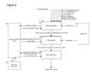
- FIG. 2 is an example of a simplified representation of the flow of information inside the device components, namely a positioning unit, a pairing unit, an assembly unit, and, optionally, an input unit, a communication unit, and a remote computer.
- FIG. 3 is an example of a simplified representation of the components of the tool, namely a positioning unit, a pairing unit, an assembly unit, and, optionally, an input unit.
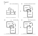
- FIG. 4 illustrates how sample partial floor plans may be positioned relatively one to another, how their walls may be paired, and how they can then be assembled into a combined floor plan.
- FIG. 1 wherein there is shown an example of a simplified flow diagram describing the various steps of the method.
- capturing positioning data from an input unit 3 and reading partial floor plan positioning data 5 can be performed in any order, even simultaneously.
- the positioning data captured from an input unit 3 comprises a translation, a rotation, and a scaling for each partial floor plan.
- the translation and the rotation may be absent or equal to zero if there is no need to translate or rotate the partial floor plan.
- the scaling may be absent or equal to one if there is no need to scale the partial floor plan.
- the positioning unit makes a first attempt at computing a translation, a rotation, and a scaling 6 in order to determine if capturing positioning data from an input unit 3 is necessary. If the positioning unit is capable of positioning a partial floor plan on its own, the user is not prompted to input positioning data.
- pairing data captured from input unit 8 comprises information that indicates that two given walls must be parallel or aligned.
- the pairing data may also comprise information that indicates that two given walls must not be parallel or aligned.
- pairing data captured from input unit 8 comprises information that indicates that the extremity of a wall must be on a straight line extending another wall.
- the pairing data may also comprise information that indicates that the extremities a wall must not be on a straight line extending another wall.
- computing paired walls 9 favors pairing a wall with the closest wall of an adjacent partial floor plan.
- computing paired walls 9 favors pairing a wall with the wall of an adjacent partial floor plan that is closest to being parallel.
- computing paired walls 9 pairs walls in a way that minimizes gaps and overlaps of partial floor plans.
- computing paired walls 9 pairs walls in a way that maximizes the number of paired walls or the total length of paired walls.
- computing paired walls 9 pairs walls by aligning doors and interior windows of a partial floor plan with those of another partial floor plan.
- a wall may be paired with multiple walls, each one being in a distinct adjacent floor plan.
- computing paired walls 9 selects the walls to pair using a Monte Carlo method, particle swarm optimization, Newton's method, a quasi-Newton's method, a gradient descent or ascent, a genetic algorithm, a simplex algorithm, simulates annealing, or a combination of the above.
- determining whether partial floor plans fit into a combined floor plan 10 minimizes the overall change in length, in position, or in orientation of walls.
- a maximum threshold may have an effect similar to the minimization in keeping the change in length, in position, or in orientation within an acceptable range.
- determining whether partial floor plans fit into a combined floor plan 10 minimizes the overall change in area or in position of rooms present in the partial floor plans.
- computing modified partial floor plans 11 may translate, rotate, and scale walls, doors and windows in order to achieve the best fit.
- Walls, doors, and interior windows may also be inserted or removed in the process.
- Properties such as wall thickness, window types, and door types may be changed when merging walls in order to improve the consistency of the combined floor plan.
- the step of computing modified partial floor plans 11 assembles the partial floor plans while maximizing a fitness function that minimizes changes to wall dimensions, to wall orientation, to the relative position of rooms, or to room areas.
- computing modified partial floor plans 11 minimizes changes to the partial floor plans using a Monte Carlo method, particle swarm optimization, Newton's method, a quasi-Newton's method, a gradient descent or ascent, a genetic algorithm, a simplex algorithm, simulates annealing, or a combination of the above.
- a partial floor plan may consist in a few wall segments, a whole room, or multiple rooms.
- a user indicates by means of the input unit that a gap between two or more partial floor plans needs to be filled with a new room that is not present in the partial floor plans.
- the assembly unit generates the new room by connecting the walls adjacent to the gap, closing open extremities of the gap if necessary. All doors and interior windows on walls adjacent to the gap now give access to this new room.
- the assembly unit determines that closing a gap between two or more partial floor plans would create deformations or tensions that are above a given tolerance threshold.
- the assembly unit thus fills the gap with a new room that is not present in the partial floor plans.
- the assembly unit generates the new room by connecting the walls adjacent to the gap, closing open extremities of the gap if necessary. All doors and interior windows on walls adjacent to the gap now give access to this new room.
- FIG. 2 wherein there is shown an example of a simplified representation of the flow of information inside the device components, namely a positioning unit 201, a pairing unit 203, an assembly unit 204, and, optionally, an input unit 202, a communication unit 205, and a remote computer 206.
- the positioning unit 201 positions partial floor plans relatively one to another using user input captured by means of an input unit 202.
- the input unit 202 comprises a touch screen allowing the user to input information using one finger, many fingers, or a stylus.
- the input unit 202 comprises a microphone coupled with a processor in order to perform voice analysis and command detection.
- the input unit 202 comprises a hardware or software keyboard.
- the input unit 202 comprises a pointing device such as a mouse, a trackball, or a joystick.
- the device also has a screen to give the user visual feedback while positioning partial floor plans or pairing walls.
- the device is a portable device such as a cellular phone, a smartphone, a laser meter, a PDA (Personal Digital Assistant), a tablet, a digital camera, or a laptop computer.
- a portable device such as a cellular phone, a smartphone, a laser meter, a PDA (Personal Digital Assistant), a tablet, a digital camera, or a laptop computer.
- the device 205 performs all or part of its computations by means of a remote computer 206.
- the device may be connected to the remote computer wirelessly or with a cable.
- the remote computer 206 may be situated near the device, allowing communication protocols such as Bluetooth or Wifi to be used, or it may be in a remote location, in which case it can be accessed via the Internet.
- FIG. 3 wherein there is shown an example of a simplified representation of the components of the tool, namely a positioning unit 301, a pairing unit 303, an assembly unit 304, and, optionally, an input unit 302.
- the tool is downloaded onto the device using a memory card, a memory stick, a cable connected to a computer, a cable connected to a network, or a wireless network connection.
- the tool is integrated with the device, either as a pre-installed application or an extension of the operating system.
- the application may be stored in ROM (Read-Only Memory) or implemented using electronic components.
- the tool is adapted to run on a portable device such as a cellular phone, a smartphone, a laser meter, a PDA (Personal Digital Assistant), a tablet, a digital camera, or a laptop computer.
- a portable device such as a cellular phone, a smartphone, a laser meter, a PDA (Personal Digital Assistant), a tablet, a digital camera, or a laptop computer.
- the tool reads the partial floor plans from a persistent storage located on the device.
- the tool reads the positioning data from a persistent storage located on the device.
- the positioning data is contained inside or attached to the partial floor plans.
- the tool previously captured the data directly from a laser distance meter, from an accelerometer, from a gyroscope, from a GPS, from a compass or from image analysis and already has this data available in RAM (random-access memory).
- the positioning unit 301 receives positioning data generated by a laser distance meter along with the partial floor plans.
- the laser distance meter measures the distance between a first partial floor plan and a reference point, followed by the distance between a second partial floor plan and the same reference point.
- the reference point may lie inside or outside the partial floor plans.
- the positioning unit 301 receives positioning data generated by an accelerometer along with the partial floor plans.
- the accelerometer measures its inclination with respect to gravity and changes in acceleration along three axes. Integrating acceleration changes over time allows determining the movements of the user in all directions with respect to time. Assuming that the user carried the accelerometer from the location represented on a first partial floor plan to the location represented on a second partial floor plan, the integration of the accelerometer data is used to compute the translation and the rotation of the partial floor plans relatively one to another. Precision depends on the quality of the accelerometer, the sampling frequency, and the algorithm used to compute the position.
- the positioning unit 301 receives positioning data generated by a gyroscope and an accelerometer along with the partial floor plans. Integrating acceleration changes over time while reading a direction from the gyroscope allows determining the movement of the user in a specific direction with respect to time. Assuming that the user carried a device comprising an accelerometer and a gyroscope from the location represented on a first partial floor plan to the location represented on a second partial floor plan, the integration of the accelerometer data in the direction indicated by the gyroscope is used to compute the translation and the rotation of the partial floor plans relatively one to another. Precision depends on the quality of the accelerometer, the sampling frequency, and the algorithm used to compute the position.
- the positioning unit 301 receives positioning data generated by a gyroscope along with the partial floor plans.
- the gyroscope measures the angle between a first partial floor plan and a reference point, followed by the angle between a second partial floor plan and the same reference point.
- the reference point may lie inside or outside the partial floor plans.
- the positioning unit 301 receives positioning data generated by a compass along with the partial floor plans.
- the compass measures the angles between the partial floor plans and a cardinal orientation. These angles are then used to determine the absolute orientation of each partial floor plan and compute the rotation necessary to position them relatively one to another. Precision depends on the quality of the compass, electromagnetic interference, and the algorithm used to compute the rotation.
- the positioning unit 301 receives positioning data generated by a GPS (Global Positioning System) along with the partial floor plans.
- GPS Global Positioning System
- a GPS measures its absolute latitude, longitude, and altitude, allowing determining the absolute position and altitude of each floor plan and computing the rotation and the translation necessary to position the partial floor plans relatively one to another.
- the altitude can be used to determine on what floor the partial floor plan was captured. Precision depends on the quality of the GPS, the number of satellites visible at the location, the latitude of the location, and the algorithm used to compute the translation.
- the positioning unit 301 receives positioning data that is the result of image analysis along with the partial floor plans.
- Image analysis extracts features from a picture or a video stream. These features can help identify structural elements such as doors, windows, walls, floors, and ceilings. Assuming that the image analysis is performed on a picture or a video stream taken on the location represented on the partial floor plans, the distance between these structural elements and their orientation is then used to compute the translation and the rotation necessary to position the partial floor plans relatively one to another. Precision depends on the resolution if the camera, the aperture angle of the camera, the ambient light, and the algorithm used to compute the translation.
- the positioning unit 301 receives positioning data that is the result of image analysis along with the partial floor plans.
- Image analysis determines if the same object is visible from multiple rooms, giving a clue as to how the partial floor plans are to be assembled. Precision depends on the resolution if the camera, the aperture angle of the camera, the ambient light, and the algorithm used to compute the translation.
- the pairing unit 303 outputs paired walls connected by strong links or weak links.
- the determination of the link strength can be based on a geometric property of the walls, such as their distance, their alignment, the correspondence of their doors and interior windows, or on user input captured by means of the input unit 302.
- Wall pairs connected by a strong link have the ability to survive the assembly process even if the combined plan induces a great tension between their respective partial floor plans, whereas those connected by weak links can be separated by the assembly unit 304 if the tension between their respective partial floor plans exceeds a certain threshold.
- FIG. 4 illustrates how sample partial floor plans 401 may be positioned relatively one to another 402, how their walls may be paired 403, and how they can then be assembled into a combined floor plan 404.
- walls are translated, rotated, or scaled in order to relax tensions, to improve consistency, to spread measurement error, to increase overall alignment or orthogonality of walls, doors, and interior windows in the combined floor plan 404.
- partial floor plans are translated, rotated, and scaled 402 by a user using a touch screen or a mouse while modifications are displayed on a screen.
- substantially aligned walls are paired 403 by a user using a touch screen or a mouse while modifications are displayed on a screen.
- a wall is inserted into or removed from a partial floor plan in order to match the wall configuration of the adjacent floor plan 404.
- a door or an interior window is translated, rotated, or scaled in order to align with a corresponding door or interior window present in the paired wall 404.
- an exterior window prevents the wall it is on from being paired with a wall in an adjacent partial floor plan, thus ensuring that the exterior window remains on an exterior wall.
- a door or an interior window is inserted or removed, or have its properties changed in order to match the configuration of doors and interior windows present in the paired wall 404.
- the combined floor plan may contain gaps or discontinuities.
- the assembly may thus generate multiple combined floor plans.
- the floor plan is never actually drawn or represented visually by the device, the tool, or the method.
- the floor plan is only manipulated as data, such as a set of points, coordinates, matrices, or an array of floating point numbers.
- This data can be stored in an XML file, a database, or a file readable by a CAD software.
Landscapes
- Physics & Mathematics (AREA)
- Engineering & Computer Science (AREA)
- General Physics & Mathematics (AREA)
- Geometry (AREA)
- Electromagnetism (AREA)
- Radar, Positioning & Navigation (AREA)
- Remote Sensing (AREA)
- Theoretical Computer Science (AREA)
- Computer Hardware Design (AREA)
- Computer Networks & Wireless Communication (AREA)
- Mathematical Analysis (AREA)
- Structural Engineering (AREA)
- Computational Mathematics (AREA)
- Civil Engineering (AREA)
- Mathematical Optimization (AREA)
- Pure & Applied Mathematics (AREA)
- Evolutionary Computation (AREA)
- General Engineering & Computer Science (AREA)
- Architecture (AREA)
- Position Fixing By Use Of Radio Waves (AREA)
- Automobile Manufacture Line, Endless Track Vehicle, Trailer (AREA)
Abstract
Description
- The present invention relates to floor plans.
- Floor plans of existing buildings are made using distance measurement tools. These tools vary in complexity and precision. An example of a distance measurement tool is the tape measure, which requires manually extending a ruler between two points and reading the distance that aligns with the second point. Another example of a distance measurement tool is the laser distance meter, which sends a laser pulse in a narrow beam towards the object and measure the time taken by the pulse to be reflected off the target and returned to the device.
- During the measuring phase, measurements are typically grouped by floor, by room, or by some other criteria that simplifies assigning them to floors, walls, doors, and windows on a floor plan. This grouping often yields partial floor plans, which then have to be assembled into a complete floor plan.
- No matter how precise the measurements, many factors may prevent partial floor plans from fitting seamlessly together. For instance, one may read different measures when measuring a wall from one side and the other; room corner angles are seldom square in reality even though they were meant to be; wall thickness is not uniform, often hiding plumbing, wires, ventilation ducts, or structural elements not apparent to the eye; floors and ceilings are not always parallel, as is the case for opposing walls; construction materials compress and stretch over time, distorting building structure.
- Floor plans were traditionally drawn by hand. They are now mostly drawn using specialized computer software. An example of specialized software is Visio, which allows drawing walls and adding furniture using a mouse and a computer running Windows. Another example of specialized software is Autocad, which allows creating detailed floor plans including of electrical wiring and plumbing layout. Specialized software typically requires that the user input measurements. It does not attempt to correct measurement errors, nor does it attempt to make various portions of a floor plan fit together.
- When assembling multiple partial floor plans, users have to adjust measurements manually to prevent floor gaps and overlaps in order to ensure consistency of the overall plan. For instance, one may force almost-square angles into square angles, even out wall thickness, spread measurement errors over multiple walls or rooms, average out multiple measurements that should have been equal, or make substantially aligned walls perfectly parallel.
- The changes made to partial floor plans in order to make them fit into a combined floor plan introduce local deformations to walls, doors, and windows. An alternate way to look at the problem at hand is to view these deformations as tensions that need to be relaxed. The greater the deformation and the higher the concentration of deformations in a given area of the floor plan, the greater the induced tension. Spreading a few local deformations over a large number of walls and over a greater area relaxes these tensions and improves the overall floor plan consistency.
- Some drawing software packages offer tools that help during the drawing process, allowing user to snap points on a grid or align walls horizontally or vertically using a mouse.
- In an aspect of the invention, there is provided a method for assembling a plurality of partial floor plans into a combined floor plan by means of an electronic device. The method comprises positioning all partial floor plans relatively one to another, pairing substantially aligned walls, and computing modified partial floor plans that can be assembled into a combined floor plan. In specific embodiments, the method may also comprise capturing user input from an input unit for positioning partial floor plans or pairing substantially aligned walls.
- In another aspect of the invention, a device for assembling a plurality of partial floor plans into a combined floor plan is provided. The device comprises a positioning unit for positioning all partial floor plans relatively one to another, a pairing unit for pairing substantially aligned walls, an assembly unit for computing modified partial floor plans that can be assembled into a combined floor plan, and, optionally, an input unit for capturing user input which is used for positioning partial floor plans or pairing substantially aligned walls.
- In another aspect of the invention, a tool for assembling a plurality of partial floor plans into a combined floor plan, adapted to run on an electronic device, is provided. The tool comprises a positioning unit for positioning all partial floor plans relatively one to another, a pairing unit for pairing substantially aligned walls, an assembly unit for computing modified partial floor plans that can be assembled into a combined floor plan, and, optionally, an input unit for capturing user input which is used for positioning partial floor plans or pairing substantially aligned walls.
-
FIG. 1 is an example of a simplified flow chart representing the various steps of the method. -
FIG. 2 is an example of a simplified representation of the flow of information inside the device components, namely a positioning unit, a pairing unit, an assembly unit, and, optionally, an input unit, a communication unit, and a remote computer. -
FIG. 3 is an example of a simplified representation of the components of the tool, namely a positioning unit, a pairing unit, an assembly unit, and, optionally, an input unit. -
FIG. 4 illustrates how sample partial floor plans may be positioned relatively one to another, how their walls may be paired, and how they can then be assembled into a combined floor plan. - Reference is now made to
FIG. 1 , wherein there is shown an example of a simplified flow diagram describing the various steps of the method. - According to one of the preferred embodiments of the invention, capturing positioning data from an
input unit 3 and reading partial floorplan positioning data 5 can be performed in any order, even simultaneously. - According to another preferred embodiment of the invention, the positioning data captured from an
input unit 3 comprises a translation, a rotation, and a scaling for each partial floor plan. The translation and the rotation may be absent or equal to zero if there is no need to translate or rotate the partial floor plan. Similarly, the scaling may be absent or equal to one if there is no need to scale the partial floor plan. - According to another preferred embodiment of the invention, the positioning unit makes a first attempt at computing a translation, a rotation, and a
scaling 6 in order to determine if capturing positioning data from aninput unit 3 is necessary. If the positioning unit is capable of positioning a partial floor plan on its own, the user is not prompted to input positioning data. - According to another preferred embodiment of the invention, pairing data captured from
input unit 8 comprises information that indicates that two given walls must be parallel or aligned. The pairing data may also comprise information that indicates that two given walls must not be parallel or aligned. - According to another preferred embodiment of the invention, pairing data captured from
input unit 8 comprises information that indicates that the extremity of a wall must be on a straight line extending another wall. The pairing data may also comprise information that indicates that the extremities a wall must not be on a straight line extending another wall. - According to another preferred embodiment of the invention, computing paired
walls 9 favors pairing a wall with the closest wall of an adjacent partial floor plan. - According to another preferred embodiment of the invention, computing paired
walls 9 favors pairing a wall with the wall of an adjacent partial floor plan that is closest to being parallel. - According to another preferred embodiment of the invention, computing paired
walls 9 pairs walls in a way that minimizes gaps and overlaps of partial floor plans. - According to another preferred embodiment of the invention, computing paired
walls 9 pairs walls in a way that maximizes the number of paired walls or the total length of paired walls. - According to another preferred embodiment of the invention, computing paired
walls 9 pairs walls by aligning doors and interior windows of a partial floor plan with those of another partial floor plan. - According to another preferred embodiment of the invention, a wall may be paired with multiple walls, each one being in a distinct adjacent floor plan.
- According to another preferred embodiment of the invention, computing paired
walls 9 selects the walls to pair using a Monte Carlo method, particle swarm optimization, Newton's method, a quasi-Newton's method, a gradient descent or ascent, a genetic algorithm, a simplex algorithm, simulates annealing, or a combination of the above. - According to another preferred embodiment of the invention, determining whether partial floor plans fit into a combined
floor plan 10 minimizes the overall change in length, in position, or in orientation of walls. Alternatively, a maximum threshold may have an effect similar to the minimization in keeping the change in length, in position, or in orientation within an acceptable range. - According to another preferred embodiment of the invention, determining whether partial floor plans fit into a combined
floor plan 10 minimizes the overall change in area or in position of rooms present in the partial floor plans. - According to another preferred embodiment of the invention, computing modified
partial floor plans 11 may translate, rotate, and scale walls, doors and windows in order to achieve the best fit. Walls, doors, and interior windows may also be inserted or removed in the process. Properties such as wall thickness, window types, and door types may be changed when merging walls in order to improve the consistency of the combined floor plan. - According to another preferred embodiment of the invention, the step of computing modified
partial floor plans 11 assembles the partial floor plans while maximizing a fitness function that minimizes changes to wall dimensions, to wall orientation, to the relative position of rooms, or to room areas. - According to another preferred embodiment of the invention, computing modified
partial floor plans 11 minimizes changes to the partial floor plans using a Monte Carlo method, particle swarm optimization, Newton's method, a quasi-Newton's method, a gradient descent or ascent, a genetic algorithm, a simplex algorithm, simulates annealing, or a combination of the above. - According to another preferred embodiment of the invention, a partial floor plan may consist in a few wall segments, a whole room, or multiple rooms.
- According to another preferred embodiment of the invention, a user indicates by means of the input unit that a gap between two or more partial floor plans needs to be filled with a new room that is not present in the partial floor plans. The assembly unit generates the new room by connecting the walls adjacent to the gap, closing open extremities of the gap if necessary. All doors and interior windows on walls adjacent to the gap now give access to this new room.
- According to another preferred embodiment of the invention, the assembly unit determines that closing a gap between two or more partial floor plans would create deformations or tensions that are above a given tolerance threshold. The assembly unit thus fills the gap with a new room that is not present in the partial floor plans. The assembly unit generates the new room by connecting the walls adjacent to the gap, closing open extremities of the gap if necessary. All doors and interior windows on walls adjacent to the gap now give access to this new room.
- Reference is now made to
FIG. 2 , wherein there is shown an example of a simplified representation of the flow of information inside the device components, namely apositioning unit 201, apairing unit 203, anassembly unit 204, and, optionally, aninput unit 202, acommunication unit 205, and aremote computer 206. - According to one of the preferred embodiments of the invention, the
positioning unit 201 positions partial floor plans relatively one to another using user input captured by means of aninput unit 202. - According to another preferred embodiment of the invention, the
input unit 202 comprises a touch screen allowing the user to input information using one finger, many fingers, or a stylus. - According to another preferred embodiment of the invention, the
input unit 202 comprises a microphone coupled with a processor in order to perform voice analysis and command detection. - According to another preferred embodiment of the invention, the
input unit 202 comprises a hardware or software keyboard. - According to another preferred embodiment of the invention, the
input unit 202 comprises a pointing device such as a mouse, a trackball, or a joystick. - According to another preferred embodiment of the invention, the device also has a screen to give the user visual feedback while positioning partial floor plans or pairing walls.
- According to another preferred embodiment of the device, the device is a portable device such as a cellular phone, a smartphone, a laser meter, a PDA (Personal Digital Assistant), a tablet, a digital camera, or a laptop computer.
- According to another preferred embodiment of the invention, the
device 205 performs all or part of its computations by means of aremote computer 206. The device may be connected to the remote computer wirelessly or with a cable. Theremote computer 206 may be situated near the device, allowing communication protocols such as Bluetooth or Wifi to be used, or it may be in a remote location, in which case it can be accessed via the Internet. - Reference is now made to
FIG. 3 , wherein there is shown an example of a simplified representation of the components of the tool, namely apositioning unit 301, apairing unit 303, anassembly unit 304, and, optionally, aninput unit 302. - According to one of the preferred embodiments of the invention, the tool is downloaded onto the device using a memory card, a memory stick, a cable connected to a computer, a cable connected to a network, or a wireless network connection.
- According to another preferred embodiment of the invention, the tool is integrated with the device, either as a pre-installed application or an extension of the operating system. The application may be stored in ROM (Read-Only Memory) or implemented using electronic components.
- According to another preferred embodiment of the invention, the tool is adapted to run on a portable device such as a cellular phone, a smartphone, a laser meter, a PDA (Personal Digital Assistant), a tablet, a digital camera, or a laptop computer.
- According to another preferred embodiment of the invention, the tool reads the partial floor plans from a persistent storage located on the device.
- According to another preferred embodiment of the invention, the tool reads the positioning data from a persistent storage located on the device.
- According to another preferred embodiment of the invention, the positioning data is contained inside or attached to the partial floor plans.
- According to another preferred embodiment of the invention, the tool previously captured the data directly from a laser distance meter, from an accelerometer, from a gyroscope, from a GPS, from a compass or from image analysis and already has this data available in RAM (random-access memory).
- According to another preferred embodiment of the invention, the
positioning unit 301 receives positioning data generated by a laser distance meter along with the partial floor plans. The laser distance meter measures the distance between a first partial floor plan and a reference point, followed by the distance between a second partial floor plan and the same reference point. The reference point may lie inside or outside the partial floor plans. These distances are then used to compute the translation and the rotation necessary to position the partial floor plans relatively one to another. - According to another preferred embodiment of the invention, the
positioning unit 301 receives positioning data generated by an accelerometer along with the partial floor plans. The accelerometer measures its inclination with respect to gravity and changes in acceleration along three axes. Integrating acceleration changes over time allows determining the movements of the user in all directions with respect to time. Assuming that the user carried the accelerometer from the location represented on a first partial floor plan to the location represented on a second partial floor plan, the integration of the accelerometer data is used to compute the translation and the rotation of the partial floor plans relatively one to another. Precision depends on the quality of the accelerometer, the sampling frequency, and the algorithm used to compute the position. - According to another preferred embodiment of the invention, the
positioning unit 301 receives positioning data generated by a gyroscope and an accelerometer along with the partial floor plans. Integrating acceleration changes over time while reading a direction from the gyroscope allows determining the movement of the user in a specific direction with respect to time. Assuming that the user carried a device comprising an accelerometer and a gyroscope from the location represented on a first partial floor plan to the location represented on a second partial floor plan, the integration of the accelerometer data in the direction indicated by the gyroscope is used to compute the translation and the rotation of the partial floor plans relatively one to another. Precision depends on the quality of the accelerometer, the sampling frequency, and the algorithm used to compute the position. - According to another preferred embodiment of the invention, the
positioning unit 301 receives positioning data generated by a gyroscope along with the partial floor plans. The gyroscope measures the angle between a first partial floor plan and a reference point, followed by the angle between a second partial floor plan and the same reference point. The reference point may lie inside or outside the partial floor plans. These angles are then used to compute the translation and the rotation necessary to position the partial floor plans relatively one to another. Precision depends on the quality of the gyroscope, the sampling frequency, and the algorithm used to compute the angles. - According to another preferred embodiment of the invention, the
positioning unit 301 receives positioning data generated by a compass along with the partial floor plans. The compass measures the angles between the partial floor plans and a cardinal orientation. These angles are then used to determine the absolute orientation of each partial floor plan and compute the rotation necessary to position them relatively one to another. Precision depends on the quality of the compass, electromagnetic interference, and the algorithm used to compute the rotation. - According to another preferred embodiment of the invention, the
positioning unit 301 receives positioning data generated by a GPS (Global Positioning System) along with the partial floor plans. A GPS measures its absolute latitude, longitude, and altitude, allowing determining the absolute position and altitude of each floor plan and computing the rotation and the translation necessary to position the partial floor plans relatively one to another. The altitude can be used to determine on what floor the partial floor plan was captured. Precision depends on the quality of the GPS, the number of satellites visible at the location, the latitude of the location, and the algorithm used to compute the translation. - According to another preferred embodiment of the invention, the
positioning unit 301 receives positioning data that is the result of image analysis along with the partial floor plans. Image analysis extracts features from a picture or a video stream. These features can help identify structural elements such as doors, windows, walls, floors, and ceilings. Assuming that the image analysis is performed on a picture or a video stream taken on the location represented on the partial floor plans, the distance between these structural elements and their orientation is then used to compute the translation and the rotation necessary to position the partial floor plans relatively one to another. Precision depends on the resolution if the camera, the aperture angle of the camera, the ambient light, and the algorithm used to compute the translation. - According to another preferred embodiment of the invention, the
positioning unit 301 receives positioning data that is the result of image analysis along with the partial floor plans. Image analysis determines if the same object is visible from multiple rooms, giving a clue as to how the partial floor plans are to be assembled. Precision depends on the resolution if the camera, the aperture angle of the camera, the ambient light, and the algorithm used to compute the translation. - According to another preferred embodiment of the invention, the
pairing unit 303 outputs paired walls connected by strong links or weak links. The determination of the link strength can be based on a geometric property of the walls, such as their distance, their alignment, the correspondence of their doors and interior windows, or on user input captured by means of theinput unit 302. Wall pairs connected by a strong link have the ability to survive the assembly process even if the combined plan induces a great tension between their respective partial floor plans, whereas those connected by weak links can be separated by theassembly unit 304 if the tension between their respective partial floor plans exceeds a certain threshold. - Reference is now made to
FIG. 4 , which illustrates how samplepartial floor plans 401 may be positioned relatively one to another 402, how their walls may be paired 403, and how they can then be assembled into a combinedfloor plan 404. - According to one of the preferred embodiments of the invention, walls are translated, rotated, or scaled in order to relax tensions, to improve consistency, to spread measurement error, to increase overall alignment or orthogonality of walls, doors, and interior windows in the combined
floor plan 404. - According to another preferred embodiment of the invention, partial floor plans are translated, rotated, and scaled 402 by a user using a touch screen or a mouse while modifications are displayed on a screen.
- According to another preferred embodiment of the invention, substantially aligned walls are paired 403 by a user using a touch screen or a mouse while modifications are displayed on a screen.
- According to another preferred embodiment of the invention, a wall is inserted into or removed from a partial floor plan in order to match the wall configuration of the
adjacent floor plan 404. - According to another preferred embodiment of the invention, a door or an interior window is translated, rotated, or scaled in order to align with a corresponding door or interior window present in the paired
wall 404. - According to another preferred embodiment of the invention, an exterior window prevents the wall it is on from being paired with a wall in an adjacent partial floor plan, thus ensuring that the exterior window remains on an exterior wall.
- According to another preferred embodiment of the invention, a door or an interior window is inserted or removed, or have its properties changed in order to match the configuration of doors and interior windows present in the paired
wall 404. - According to another preferred embodiment of the invention, the combined floor plan may contain gaps or discontinuities. The assembly may thus generate multiple combined floor plans.
- According to another preferred embodiment of the invention, the floor plan is never actually drawn or represented visually by the device, the tool, or the method. The floor plan is only manipulated as data, such as a set of points, coordinates, matrices, or an array of floating point numbers. This data can be stored in an XML file, a database, or a file readable by a CAD software.
Claims (15)
- A method for assembling a plurality of partial floor plans into a combined floor plan by means of an electronic device, the method comprising:positioning the partial floor plans relatively one to another;pairing substantially aligned walls;computing modified partial floor plans that can be assembled into a combined floor plan.
- The method of claim 1, wherein the positioning of the partial floor plans relatively one to another is performed by computing a translation, a rotation, or a scaling of each partial floor plan using at least one of the following:a distance between two walls;an angle between two walls;a similarity in shape of a series of walls contained in two of the partial floor plans;an alignment of an interior door or opening with a corresponding interior door oropening in another partial floor plan;an exterior door or opening preventing its supporting wall from being paired with a wall of another partial floor plan;a distance between one of the partial floor plans and a reference point measured using data read from a laser distance meter;a path between two of the partial floor plans computed by integrating data read from an accelerometer over time;an orientation of one of the partial floor plans relative to the magnetic or geographic north measured using a compass;a latitude, a longitude, or an altitude of one of the partial floor plans measured using data read from a GPS;an angle between one of the partial floor plans and a reference point measured using data read from a gyroscope or a rotary encoder;a direction along a path between two of the partial floor plans identified using data read from a gyroscope or a rotary encoder;user input captured by means of an input unit;the presence of a reference object identified using image analysis on several images of the location represented on the floor plan.
- The method of claim 1, wherein the pairing of substantially aligned walls comprises at least one of the following:minimizing the difference between the length of two paired walls;minimizing the angle between two paired walls;minimizing the displacement of the partial floor plans;minimizing the overlap of the partial floor plans;minimizing the gap between the partial floor plans;maximizing the total length of all paired walls;maximizing the number of paired walls;maximizing the alignment of doors or interior openings present in two paired walls;favoring or forcing the pairing of two walls selected by means of an input unit;disfavoring or preventing the pairing of two walls selected by means of an input unit;maximizing a fitness function combining several of the above.
- The method of claim 1, wherein computing modified partial floor plans minimizes changes to the partial floor plans while performing at least one of the following:translating a wall, a door, or an opening;rotating a wall, a door, or an opening;deforming a wall, a door, or an opening;changing a property of a wall, a door, or an opening;inserting a wall, a door or an opening;removing a wall, a door or an opening.
- The method of claim 1, wherein the device further comprises a communication unit for performing portions of at least one of the following computations on a remote computer:positioning partial floor plans relatively one to another;pairing substantially aligned walls;computing modified partial floor plans that can be assembled into a combined floor plan.
- A device for assembling a plurality of partial floor plans into a combined floor plan, the device comprising:a positioning unit for positioning the partial floor plans relatively one to another;a pairing unit for pairing substantially aligned walls;an assembly unit for computing modified partial floor plans that can be assembled into a combined floor plan.
- The device of claim 6, wherein the positioning unit positions the partial floor plans relatively one to another by computing a translation, a rotation, or a scaling of each partial floor plan using at least one of the following:a distance between two walls;an angle between two walls;a similarity in shape of a series of walls contained in two of the partial floor plans;an alignment of an interior door or opening with a corresponding interior door oropening in another partial floor plan;an exterior door or opening preventing its supporting wall from being paired with a wall of another partial floor plan;a distance between one of the partial floor plans and a reference point measured using data read from a laser distance meter;a path between two of the partial floor plans computed by integrating data read from an accelerometer over time;an orientation of one of the partial floor plans relative to the magnetic or geographic north measured using a compass;a latitude, a longitude, or an altitude of one of the partial floor plans measured using data read from a GPS;an angle between one of the partial floor plans and a reference point measured using data read from a gyroscope or a rotary encoder;a direction along a path between two of the partial floor plans identified using data read from a gyroscope or a rotary encoder;user input captured by means of an input unit;the presence of a reference object identified using image analysis on several images of the location represented on the floor plan.
- The device of claim 6, wherein the pairing unit performs at least one of the following:minimizing the difference between the length of two paired walls;minimizing the angle between two paired walls;minimizing the displacement of the partial floor plans;minimizing the overlap of the partial floor plans;minimizing the gap between the partial floor plans;maximizing the total length of all paired walls;maximizing the number of paired walls;maximizing the alignment of doors or interior openings present in two paired walls;favoring or forcing the pairing of two walls selected by means of an input unit;disfavoring or preventing the pairing of two walls selected by means of an input unit;maximizing a fitness function combining several of the above.
- The device of claim 6, wherein the assembly unit minimizes changes to the partial floor plans while performing at least one of the following:translating a wall, a door, or an opening;rotating a wall, a door, or an opening;scaling a wall, a door, or an opening;changing a property of a wall, a door, or an opening;inserting a wall, a door or an opening;removing a wall, a door or an opening.
- The device of claim 6, further comprising a communication unit for performing portions of at least one of the following computations on a remote computer:positioning partial floor plans relatively one to another;pairing substantially aligned walls;computing modified partial floor plans that can be assembled into a combined floor plan.
- A tool for assembling a plurality of partial floor plans into a combined floor plan, adapted to run on an electronic device, the tool comprising:a positioning unit for positioning the partial floor plans relatively one to another;a pairing unit for pairing substantially aligned walls;an assembly unit for modifying partial floor plans so they can be assembled into a combined floor plan.
- The tool of claim 11, wherein the positioning unit positions the partial floor plans relatively one to another by computing a translation, a rotation, or a scaling of each partial floor plan using at least one of the following:a distance between two walls;an angle between two walls;a similarity in shape of a series of walls contained in two of the partial floor plans;an alignment of an interior door or opening with a corresponding interior door oropening in another partial floor plan;an exterior door or opening preventing its supporting wall from being paired with a wall of another partial floor plan;a distance between one of the partial floor plans and a reference point measured using data read from a laser distance meter;a path between two of the partial floor plans computed by integrating data read from an accelerometer over time;an orientation of one of the partial floor plans relative to the magnetic or geographic north measured using a compass;a latitude, a longitude, or an altitude of one of the partial floor plans measured using data read from a GPS;an angle between one of the partial floor plans and a reference point measured using data read from a gyroscope or a rotary encoder;a direction along a path between two of the partial floor plans identified using data read from a gyroscope or a rotary encoder;user input captured by means of an input unit;the presence of a reference object identified using image analysis on several images of the location represented on the floor plan.
- The tool of claim 11, wherein the pairing unit performs at least one of the following:minimizing the difference between the length of two paired walls;minimizing the angle between two paired walls;minimizing the displacement of the partial floor plans;minimizing the overlap of the partial floor plans;minimizing the gap between the partial floor plans;maximizing the total length of all paired walls;maximizing the number of paired walls;maximizing the alignment of doors or interior openings present in two paired walls;favoring or forcing the pairing of two walls selected by means of an input unit;disfavoring or preventing the pairing of two walls selected by means of an input unit;maximizing a fitness function combining several of the above.
- The tool of claim 11, wherein the assembly unit minimizes changes to the partial floor plans while performing at least one of the following:translating a wall, a door, or an opening;rotating a wall, a door, or an opening;scaling a wall, a door, or an opening;changing a property of a wall, a door, or an opening;inserting a wall, a door or an opening;removing a wall, a door or an opening.
- The tool of claim 11, wherein the device further comprises a communication unit for performing portions of at least one of the following computations on a remote computer:positioning partial floor plans relatively one to another;pairing substantially aligned walls;computing modified partial floor plans that can be assembled into a combined floor plan.
Applications Claiming Priority (1)
| Application Number | Priority Date | Filing Date | Title |
|---|---|---|---|
| US13/077,938 US8996336B2 (en) | 2011-03-31 | 2011-03-31 | Method, tool, and device for assembling a plurality of partial floor plans into a combined floor plan |
Publications (2)
| Publication Number | Publication Date |
|---|---|
| EP2506170A2 true EP2506170A2 (en) | 2012-10-03 |
| EP2506170A3 EP2506170A3 (en) | 2013-08-21 |
Family
ID=45954370
Family Applications (1)
| Application Number | Title | Priority Date | Filing Date |
|---|---|---|---|
| EP12161173.5A Withdrawn EP2506170A3 (en) | 2011-03-31 | 2012-03-26 | Method, tool, and device for assembling a plurality of partial floor plans into a combined floor plan |
Country Status (2)
| Country | Link |
|---|---|
| US (1) | US8996336B2 (en) |
| EP (1) | EP2506170A3 (en) |
Cited By (23)
| Publication number | Priority date | Publication date | Assignee | Title |
|---|---|---|---|---|
| WO2017198836A1 (en) * | 2016-05-20 | 2017-11-23 | Achoice Ab | Component-based architectural design of a floor plan of a building or an outdoor space |
| US10530997B2 (en) | 2017-07-13 | 2020-01-07 | Zillow Group, Inc. | Connecting and using building interior data acquired from mobile devices |
| US10643386B2 (en) | 2018-04-11 | 2020-05-05 | Zillow Group, Inc. | Presenting image transition sequences between viewing locations |
| US10708507B1 (en) | 2018-10-11 | 2020-07-07 | Zillow Group, Inc. | Automated control of image acquisition via use of acquisition device sensors |
| US10809066B2 (en) | 2018-10-11 | 2020-10-20 | Zillow Group, Inc. | Automated mapping information generation from inter-connected images |
| US10825247B1 (en) | 2019-11-12 | 2020-11-03 | Zillow Group, Inc. | Presenting integrated building information using three-dimensional building models |
| US11057561B2 (en) | 2017-07-13 | 2021-07-06 | Zillow, Inc. | Capture, analysis and use of building data from mobile devices |
| US11164361B2 (en) | 2019-10-28 | 2021-11-02 | Zillow, Inc. | Generating floor maps for buildings from automated analysis of visual data of the buildings' interiors |
| US11164368B2 (en) | 2019-10-07 | 2021-11-02 | Zillow, Inc. | Providing simulated lighting information for three-dimensional building models |
| US11243656B2 (en) | 2019-08-28 | 2022-02-08 | Zillow, Inc. | Automated tools for generating mapping information for buildings |
| US11252329B1 (en) | 2021-01-08 | 2022-02-15 | Zillow, Inc. | Automated determination of image acquisition locations in building interiors using multiple data capture devices |
| US11405549B2 (en) | 2020-06-05 | 2022-08-02 | Zillow, Inc. | Automated generation on mobile devices of panorama images for building locations and subsequent use |
| US11481925B1 (en) | 2020-11-23 | 2022-10-25 | Zillow, Inc. | Automated determination of image acquisition locations in building interiors using determined room shapes |
| US11480433B2 (en) | 2018-10-11 | 2022-10-25 | Zillow, Inc. | Use of automated mapping information from inter-connected images |
| US11501492B1 (en) | 2021-07-27 | 2022-11-15 | Zillow, Inc. | Automated room shape determination using visual data of multiple captured in-room images |
| US11514674B2 (en) | 2020-09-04 | 2022-11-29 | Zillow, Inc. | Automated analysis of image contents to determine the acquisition location of the image |
| US11592969B2 (en) | 2020-10-13 | 2023-02-28 | MFTB Holdco, Inc. | Automated tools for generating building mapping information |
| US11632602B2 (en) | 2021-01-08 | 2023-04-18 | MFIB Holdco, Inc. | Automated determination of image acquisition locations in building interiors using multiple data capture devices |
| US11676344B2 (en) | 2019-11-12 | 2023-06-13 | MFTB Holdco, Inc. | Presenting building information using building models |
| US11790648B2 (en) | 2021-02-25 | 2023-10-17 | MFTB Holdco, Inc. | Automated usability assessment of buildings using visual data of captured in-room images |
| US11830135B1 (en) | 2022-07-13 | 2023-11-28 | MFTB Holdco, Inc. | Automated building identification using floor plans and acquired building images |
| US11836973B2 (en) | 2021-02-25 | 2023-12-05 | MFTB Holdco, Inc. | Automated direction of capturing in-room information for use in usability assessment of buildings |
| US11842464B2 (en) | 2021-09-22 | 2023-12-12 | MFTB Holdco, Inc. | Automated exchange and use of attribute information between building images of multiple types |
Families Citing this family (14)
| Publication number | Priority date | Publication date | Assignee | Title |
|---|---|---|---|---|
| US9501700B2 (en) | 2012-02-15 | 2016-11-22 | Xactware Solutions, Inc. | System and method for construction estimation using aerial images |
| US9275282B2 (en) * | 2012-10-30 | 2016-03-01 | Qualcomm Incorporated | Processing and managing multiple maps for an LCI |
| US20140201210A1 (en) * | 2013-01-14 | 2014-07-17 | Qualcomm Incorporated | Automatic model selection for assistance data generation based on apriori information |
| US20140330541A1 (en) * | 2013-05-01 | 2014-11-06 | Fluke Networks Inc. | Floor alignment in multi-floor building |
| US9456307B2 (en) * | 2013-05-29 | 2016-09-27 | Apple Inc. | Electronic device with mapping circuitry |
| WO2015017855A1 (en) | 2013-08-02 | 2015-02-05 | Xactware Solutions, Inc. | System and method for detecting features in aerial images using disparity mapping and segmentation techniques |
| WO2015123348A1 (en) | 2014-02-11 | 2015-08-20 | Xactware Solutions, Inc. | System and method for generating computerized floor plans |
| EP3387623A4 (en) | 2015-12-09 | 2019-07-10 | Geomni, Inc. | System and method for generating computerized models of structures using geometry extraction and reconstruction techniques |
| US10555181B2 (en) | 2017-05-03 | 2020-02-04 | ARRIS Enterprises, LLC | Determining transceiver height |
| EP3710963A4 (en) | 2017-11-13 | 2021-08-04 | Geomni, Inc. | Systems and methods for rapidly developing annotated computer models of structures |
| US10891769B2 (en) * | 2019-02-14 | 2021-01-12 | Faro Technologies, Inc | System and method of scanning two dimensional floorplans using multiple scanners concurrently |
| US11094113B2 (en) | 2019-12-04 | 2021-08-17 | Geomni, Inc. | Systems and methods for modeling structures using point clouds derived from stereoscopic image pairs |
| US11481704B2 (en) * | 2021-03-09 | 2022-10-25 | Togal.Ai Inc. | Methods and apparatus for artificial intelligence conversion of change orders into an actionable interface |
| WO2022204559A1 (en) | 2021-03-25 | 2022-09-29 | Insurance Services Office, Inc. | Computer vision systems and methods for generating building models using three-dimensional sensing and augmented reality techniques |
Family Cites Families (5)
| Publication number | Priority date | Publication date | Assignee | Title |
|---|---|---|---|---|
| US7039569B1 (en) * | 2000-06-09 | 2006-05-02 | Haws Richard R | Automatic adaptive dimensioning for CAD software |
| US7302359B2 (en) * | 2006-02-08 | 2007-11-27 | Honeywell International Inc. | Mapping systems and methods |
| US8122370B2 (en) * | 2006-11-27 | 2012-02-21 | Designin Corporation | Visual bookmarks for home and landscape design |
| US8260581B2 (en) * | 2006-11-27 | 2012-09-04 | Designin Corporation | Joining and disjoining individual rooms in a floor plan |
| US9213785B2 (en) * | 2009-02-03 | 2015-12-15 | Thomas Plewe | Systems and methods for component-based architecture design |
-
2011
- 2011-03-31 US US13/077,938 patent/US8996336B2/en active Active
-
2012
- 2012-03-26 EP EP12161173.5A patent/EP2506170A3/en not_active Withdrawn
Non-Patent Citations (1)
| Title |
|---|
| None |
Cited By (39)
| Publication number | Priority date | Publication date | Assignee | Title |
|---|---|---|---|---|
| WO2017198836A1 (en) * | 2016-05-20 | 2017-11-23 | Achoice Ab | Component-based architectural design of a floor plan of a building or an outdoor space |
| US11182512B2 (en) | 2016-05-20 | 2021-11-23 | Achoice Ab | Component-based architectural design of a floor plan of a building or an outdoor space |
| US11165959B2 (en) | 2017-07-13 | 2021-11-02 | Zillow, Inc. | Connecting and using building data acquired from mobile devices |
| US10530997B2 (en) | 2017-07-13 | 2020-01-07 | Zillow Group, Inc. | Connecting and using building interior data acquired from mobile devices |
| US11632516B2 (en) | 2017-07-13 | 2023-04-18 | MFIB Holdco, Inc. | Capture, analysis and use of building data from mobile devices |
| US10834317B2 (en) | 2017-07-13 | 2020-11-10 | Zillow Group, Inc. | Connecting and using building data acquired from mobile devices |
| US11057561B2 (en) | 2017-07-13 | 2021-07-06 | Zillow, Inc. | Capture, analysis and use of building data from mobile devices |
| US10643386B2 (en) | 2018-04-11 | 2020-05-05 | Zillow Group, Inc. | Presenting image transition sequences between viewing locations |
| US11217019B2 (en) | 2018-04-11 | 2022-01-04 | Zillow, Inc. | Presenting image transition sequences between viewing locations |
| US11405558B2 (en) | 2018-10-11 | 2022-08-02 | Zillow, Inc. | Automated control of image acquisition via use of hardware sensors and camera content |
| US10809066B2 (en) | 2018-10-11 | 2020-10-20 | Zillow Group, Inc. | Automated mapping information generation from inter-connected images |
| US10708507B1 (en) | 2018-10-11 | 2020-07-07 | Zillow Group, Inc. | Automated control of image acquisition via use of acquisition device sensors |
| US11638069B2 (en) | 2018-10-11 | 2023-04-25 | MFTB Holdco, Inc. | Automated control of image acquisition via use of mobile device user interface |
| US11480433B2 (en) | 2018-10-11 | 2022-10-25 | Zillow, Inc. | Use of automated mapping information from inter-connected images |
| US11627387B2 (en) | 2018-10-11 | 2023-04-11 | MFTB Holdco, Inc. | Automated control of image acquisition via use of mobile device interface |
| US11408738B2 (en) | 2018-10-11 | 2022-08-09 | Zillow, Inc. | Automated mapping information generation from inter-connected images |
| US11284006B2 (en) | 2018-10-11 | 2022-03-22 | Zillow, Inc. | Automated control of image acquisition via acquisition location determination |
| US11243656B2 (en) | 2019-08-28 | 2022-02-08 | Zillow, Inc. | Automated tools for generating mapping information for buildings |
| US11164368B2 (en) | 2019-10-07 | 2021-11-02 | Zillow, Inc. | Providing simulated lighting information for three-dimensional building models |
| US11823325B2 (en) | 2019-10-07 | 2023-11-21 | MFTB Holdco, Inc. | Providing simulated lighting information for building models |
| US11494973B2 (en) | 2019-10-28 | 2022-11-08 | Zillow, Inc. | Generating floor maps for buildings from automated analysis of visual data of the buildings' interiors |
| US11164361B2 (en) | 2019-10-28 | 2021-11-02 | Zillow, Inc. | Generating floor maps for buildings from automated analysis of visual data of the buildings' interiors |
| US11935196B2 (en) | 2019-11-12 | 2024-03-19 | MFTB Holdco, Inc. | Presenting building information using building models |
| US11238652B2 (en) | 2019-11-12 | 2022-02-01 | Zillow, Inc. | Presenting integrated building information using building models |
| US11676344B2 (en) | 2019-11-12 | 2023-06-13 | MFTB Holdco, Inc. | Presenting building information using building models |
| US10825247B1 (en) | 2019-11-12 | 2020-11-03 | Zillow Group, Inc. | Presenting integrated building information using three-dimensional building models |
| US11405549B2 (en) | 2020-06-05 | 2022-08-02 | Zillow, Inc. | Automated generation on mobile devices of panorama images for building locations and subsequent use |
| US11514674B2 (en) | 2020-09-04 | 2022-11-29 | Zillow, Inc. | Automated analysis of image contents to determine the acquisition location of the image |
| US11592969B2 (en) | 2020-10-13 | 2023-02-28 | MFTB Holdco, Inc. | Automated tools for generating building mapping information |
| US11797159B2 (en) | 2020-10-13 | 2023-10-24 | MFTB Holdco, Inc. | Automated tools for generating building mapping information |
| US11645781B2 (en) | 2020-11-23 | 2023-05-09 | MFTB Holdco, Inc. | Automated determination of acquisition locations of acquired building images based on determined surrounding room data |
| US11481925B1 (en) | 2020-11-23 | 2022-10-25 | Zillow, Inc. | Automated determination of image acquisition locations in building interiors using determined room shapes |
| US11632602B2 (en) | 2021-01-08 | 2023-04-18 | MFIB Holdco, Inc. | Automated determination of image acquisition locations in building interiors using multiple data capture devices |
| US11252329B1 (en) | 2021-01-08 | 2022-02-15 | Zillow, Inc. | Automated determination of image acquisition locations in building interiors using multiple data capture devices |
| US11790648B2 (en) | 2021-02-25 | 2023-10-17 | MFTB Holdco, Inc. | Automated usability assessment of buildings using visual data of captured in-room images |
| US11836973B2 (en) | 2021-02-25 | 2023-12-05 | MFTB Holdco, Inc. | Automated direction of capturing in-room information for use in usability assessment of buildings |
| US11501492B1 (en) | 2021-07-27 | 2022-11-15 | Zillow, Inc. | Automated room shape determination using visual data of multiple captured in-room images |
| US11842464B2 (en) | 2021-09-22 | 2023-12-12 | MFTB Holdco, Inc. | Automated exchange and use of attribute information between building images of multiple types |
| US11830135B1 (en) | 2022-07-13 | 2023-11-28 | MFTB Holdco, Inc. | Automated building identification using floor plans and acquired building images |
Also Published As
| Publication number | Publication date |
|---|---|
| US8996336B2 (en) | 2015-03-31 |
| US20120253751A1 (en) | 2012-10-04 |
| EP2506170A3 (en) | 2013-08-21 |
Similar Documents
| Publication | Publication Date | Title |
|---|---|---|
| US8996336B2 (en) | Method, tool, and device for assembling a plurality of partial floor plans into a combined floor plan | |
| US20200408532A1 (en) | Automated Mapping Information Generation From Inter-Connected Images | |
| US11480433B2 (en) | Use of automated mapping information from inter-connected images | |
| US11243656B2 (en) | Automated tools for generating mapping information for buildings | |
| AU2019356907B2 (en) | Automated control of image acquisition via use of acquisition device sensors | |
| US7398481B2 (en) | Virtual environment capture | |
| US20220309204A1 (en) | System and Method for Generating Computerized Floor Plans | |
| JP6490220B2 (en) | 3D autostereoscopic modeling method and program based on 2D drawing | |
| US10467758B1 (en) | Imagery-based construction progress tracking | |
| US10458798B2 (en) | Method for sensing interior spaces to auto-generate a navigational map | |
| US9151608B2 (en) | Apparatus, tool, and method for modifying a portion of a floor plan based on measurements made by one or more sensors | |
| US20160300389A1 (en) | Correlated immersive virtual simulation for indoor navigation | |
| US11514674B2 (en) | Automated analysis of image contents to determine the acquisition location of the image | |
| Gomez-Jauregui et al. | Quantitative evaluation of overlaying discrepancies in mobile augmented reality applications for AEC/FM | |
| US11961180B2 (en) | Method for generating roof outlines from lateral images | |
| US7181371B2 (en) | Apparatus and method for inputting measurements into a software product to construct software models of architectural structures | |
| Degani et al. | An automated system for projection of interior construction layouts | |
| KR101902131B1 (en) | System for producing simulation panoramic indoor images | |
| EP4256424A1 (en) | Collaborative augmented reality measurement systems and methods | |
| Murari et al. | Cross-platform immersive visualization and navigation with augmented reality | |
| Frangez et al. | Comparison of three innovative technologies for 3D-acquisition, modelling, and visualization of an underground mine | |
| Klug et al. | On using 3D support geometries for measuring human-made corner structures with a robotic total station | |
| Kushnir | The benefits of 3D laser scanning | |
| CN116311335A (en) | Engineering drawing data extraction method and device | |
| CN118036116A (en) | Automated inter-image analysis of multiple building images for building floor plan generation |
Legal Events
| Date | Code | Title | Description |
|---|---|---|---|
| PUAI | Public reference made under article 153(3) epc to a published international application that has entered the european phase |
Free format text: ORIGINAL CODE: 0009012 |
|
| AK | Designated contracting states |
Kind code of ref document: A2 Designated state(s): AL AT BE BG CH CY CZ DE DK EE ES FI FR GB GR HR HU IE IS IT LI LT LU LV MC MK MT NL NO PL PT RO RS SE SI SK SM TR |
|
| AX | Request for extension of the european patent |
Extension state: BA ME |
|
| PUAL | Search report despatched |
Free format text: ORIGINAL CODE: 0009013 |
|
| AK | Designated contracting states |
Kind code of ref document: A3 Designated state(s): AL AT BE BG CH CY CZ DE DK EE ES FI FR GB GR HR HU IE IS IT LI LT LU LV MC MK MT NL NO PL PT RO RS SE SI SK SM TR |
|
| AX | Request for extension of the european patent |
Extension state: BA ME |
|
| RIC1 | Information provided on ipc code assigned before grant |
Ipc: G01S 17/08 20060101ALN20130715BHEP Ipc: G06T 7/00 20060101ALN20130715BHEP Ipc: G06F 17/50 20060101AFI20130715BHEP Ipc: G01C 15/00 20060101ALN20130715BHEP |
|
| 17P | Request for examination filed |
Effective date: 20140217 |
|
| RBV | Designated contracting states (corrected) |
Designated state(s): AL AT BE BG CH CY CZ DE DK EE ES FI FR GB GR HR HU IE IS IT LI LT LU LV MC MK MT NL NO PL PT RO RS SE SI SK SM TR |
|
| 17Q | First examination report despatched |
Effective date: 20180206 |
|
| STAA | Information on the status of an ep patent application or granted ep patent |
Free format text: STATUS: THE APPLICATION IS DEEMED TO BE WITHDRAWN |
|
| 18D | Application deemed to be withdrawn |
Effective date: 20200212 |