EP2505453A2 - Transport cart - Google Patents
Transport cart Download PDFInfo
- Publication number
- EP2505453A2 EP2505453A2 EP12154249A EP12154249A EP2505453A2 EP 2505453 A2 EP2505453 A2 EP 2505453A2 EP 12154249 A EP12154249 A EP 12154249A EP 12154249 A EP12154249 A EP 12154249A EP 2505453 A2 EP2505453 A2 EP 2505453A2
- Authority
- EP
- European Patent Office
- Prior art keywords
- support frame
- trolley according
- chassis
- trolley
- guide slot
- Prior art date
- Legal status (The legal status is an assumption and is not a legal conclusion. Google has not performed a legal analysis and makes no representation as to the accuracy of the status listed.)
- Granted
Links
Images

Classifications
-
- B—PERFORMING OPERATIONS; TRANSPORTING
- B62—LAND VEHICLES FOR TRAVELLING OTHERWISE THAN ON RAILS
- B62B—HAND-PROPELLED VEHICLES, e.g. HAND CARTS OR PERAMBULATORS; SLEDGES
- B62B3/00—Hand carts having more than one axis carrying transport wheels; Steering devices therefor; Equipment therefor
- B62B3/08—Hand carts having more than one axis carrying transport wheels; Steering devices therefor; Equipment therefor involving tiltably-mounted containers
-
- B—PERFORMING OPERATIONS; TRANSPORTING
- B62—LAND VEHICLES FOR TRAVELLING OTHERWISE THAN ON RAILS
- B62B—HAND-PROPELLED VEHICLES, e.g. HAND CARTS OR PERAMBULATORS; SLEDGES
- B62B2202/00—Indexing codes relating to type or characteristics of transported articles
- B62B2202/12—Boxes, Crates
-
- B—PERFORMING OPERATIONS; TRANSPORTING
- B62—LAND VEHICLES FOR TRAVELLING OTHERWISE THAN ON RAILS
- B62B—HAND-PROPELLED VEHICLES, e.g. HAND CARTS OR PERAMBULATORS; SLEDGES
- B62B2203/00—Grasping, holding, supporting the objects
- B62B2203/02—Grasping, holding, supporting the objects suspended
-
- B—PERFORMING OPERATIONS; TRANSPORTING
- B62—LAND VEHICLES FOR TRAVELLING OTHERWISE THAN ON RAILS
- B62B—HAND-PROPELLED VEHICLES, e.g. HAND CARTS OR PERAMBULATORS; SLEDGES
- B62B2203/00—Grasping, holding, supporting the objects
- B62B2203/07—Comprising a moving platform or the like, e.g. for unloading
Definitions
- the invention relates to a trolley with a chassis and a support frame mounted thereon for receiving a container having an upper opening for filling and for removal of cargo.
- a trolley of the type outlined above is from the German utility model 20 2009 008 725 known.
- the support frame for receiving the container is mounted on two parallel, inclined roller conveyors, so that it can be pushed from the transport position on the chassis to the ground, where the roller-guided support frame remains during the removal of the transported goods from the container.
- a disadvantage of the known systems is the fact that the containers used, such as lattice boxes, are relatively high, so that they are awkward to empty even in their position on the ground.
- the operator reaches the parts to be removed only with the arms extended upwards, while objects lying on the container base are reached only with difficulty or with the aid of gripping tools.
- the invention has for its object to provide a trolley of the type outlined at the outset, which remains with the semi-mounted container at the site and allows easy removal of the required items.
- the support frame is mounted on both sides tiltable on a chassis about a horizontal axis from a vertical transport position in which the opening of the container facing upward.
- the support frame has two lying in parallel vertical planes, part-circular swing skids, each of which is in engagement with a mounted on the chassis, also part-circular guide slot.
- each of the two lying in parallel vertical planes guide slots consists of a cross-sectionally C-shaped rail, engage in the rotatable about horizontal axes support rollers which protrude from the associated oscillating runner of the support frame.
- guide rollers are freely rotatably mounted on each swing runner, which are supported on an opposite vertical surface of the guide slot and whose axes of rotation extend radially to the horizontal tilt axis.
- a parallel to the horizontal tilting axis adjustable, spring-loaded bolt is arranged in a further development of the invention on one of the two swing skids, for the latching engagement three holes are mounted in the opposite guide slot.
- the three holes have an angular distance of 30 ° to each other.
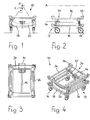
- the trolley designated generally by 10 in the figures, has a rectangular chassis 12 in plan view, at the four corners of which a steering roller 14 is attached.
- the chassis 12 consists of two parallel longitudinal members 16, which are interconnected via two cross members 18.
- each guide slot 20 consists of a cross-sectionally C-shaped rail 22nd
- a support frame 24 is mounted, which also has the shape of a chassis 12 corresponding to the rectangle in plan view.
- the support frame 24 has two outer longitudinal beams 26, which extend parallel to the longitudinal members 16 of the chassis 12 and which are connected to each other at both ends by a cross member 28.
- a rocking runner 30 is fixed, which is formed part-circular and the pitch circle shape of the associated guide slot 20 corresponds.
- the swing skids 30 lie in two parallel vertical planes corresponding to the vertical planes of the two guide slots 20.
- each rocker 30 of the support frame 24 three support rollers 32 are mounted, which are freely rotatable about their associated horizontal axis. All three support rollers 32 of each rocker 30 serve to engage in the C-shaped rail 22 of the guide slot 20, so that the support frame 24 almost frictionless on the chassis 12 about a longitudinally extending tilt axis A (see. FIG. 1 ) can be swiveled.
- the tilting axis A forms the center of each of the two part-circular swing runners 30 and guide slots 20.
- guide rollers 34 which are freely rotatably mounted on each of the two swing skids 30 about axes of rotation which extend radially to the horizontal tilt axis A.
- the guide rollers 34 are supported on the respective opposite vertical surface 38 of the C-shaped rail 22.
- the support frame 24 serves to receive a container, not shown, which is supported at the corners of the support frame 24 at upwardly projecting stop angles 36.
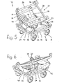
- the support frame 24 can be in both the vertical transport position of the container, made up FIG. 4 results, as well as in the two lateral tilt positions after the FIGS. 5 to 8 be locked.
- a parallel to the horizontal tilt axis A aligned bolt 46 is provided on one of the two swing skids 30, which can be adjusted against a spring in the axial direction.
- a total of three holes 40 are mounted in the opposite guide slot 20.
- the two outer holes 40 have an angular distance ⁇ of 30 ° to the central bore 40 (see. FIG. 1 ).
- the axially adjustable bolt 46 is mounted in a longitudinally extending tube 42 which connects the two swing blades 30 centered together. On this tube 42, the middle of the three support rollers 32 is mounted, which is constantly in engagement with the C-shaped rail 22 of the guide slot 20.
- the center of gravity S (see FIG. FIG. 1 ) of the load, not shown, generally a container, located below the tilt axis A.
- the center of gravity S 30 ° to both sides of the load center of gravity S then always remains between the castors 14 of the chassis 12, so that the loaded trolley 10 can not tilt.
Landscapes
- Engineering & Computer Science (AREA)
- Chemical & Material Sciences (AREA)
- Combustion & Propulsion (AREA)
- Transportation (AREA)
- Mechanical Engineering (AREA)
- Handcart (AREA)
Abstract
Description
Die Erfindung betrifft einen Transportwagen mit einem Fahrgestell und einem auf diesem gelagerten Tragrahmen zur Aufnahme eines Behälters mit einer oberen Öffnung zum Einfüllen und zur Entnahme von Transportgut.The invention relates to a trolley with a chassis and a support frame mounted thereon for receiving a container having an upper opening for filling and for removal of cargo.
Mit Hilfe eines solchen Transportwagens werden in der industriellen Fertigung Transportgüter, beispielsweise Maschinenteile, Einzelteile oder Ersatzteile, von einem Lager zum Einsatzort befördert, beispielsweise einem Montageplatz. Der Transportwagen wird hierzu nach der Beladung mit dem Behälter, z. B. einer Gitterbox oder einer Normkiste, im Zugverbund eines Routenzugs mitgenommen und am Montageplatz abgestellt, wo das zuständige Personal die Teile zur Weiterverarbeitung einzeln entnimmt.With the help of such a transport vehicle in industrial manufacturing transport goods, such as machine parts, items or spare parts, transported from a warehouse to the place of use, such as a mounting station. The dolly is this purpose after loading with the container, z. As a lattice box or a standard box, taken in the train group of a tugger train and parked at the assembly site, where the responsible personnel individually removes the parts for further processing.
Ein Transportwagen der eingangs umrissenen Bauart ist aus dem deutschen Gebrauchsmuster
Nachteilig bei den bekannten Systemen ist die Tatsache, dass die eingesetzten Behälter, beispielsweise Gitterboxen, verhältnismäßig hoch sind, so dass sie auch in ihrer Stellung auf dem Boden umständlich zu entleeren sind. Zur Entnahme der im Bereich der Behälteröffnung liegenden Gegenstände erreicht die Bedienungsperson die zu entnehmenden Teile nur mit nach oben gestreckten Armen, während am Behältergrund liegende Gegenstände nur mit Mühe oder unter Zuhilfenahme von Greifwerkzeugen erreicht werden.A disadvantage of the known systems is the fact that the containers used, such as lattice boxes, are relatively high, so that they are awkward to empty even in their position on the ground. To remove the objects lying in the region of the container opening, the operator reaches the parts to be removed only with the arms extended upwards, while objects lying on the container base are reached only with difficulty or with the aid of gripping tools.
Der Erfindung liegt die Aufgabe zugrunde, einen Transportwagen der eingangs umrissenen Bauart zur Verfügung zu stellen, der mit dem aufgesattelten Behälter am Einsatzort verbleibt und eine bequeme Entnahme der benötigten Gegenstände ermöglicht.The invention has for its object to provide a trolley of the type outlined at the outset, which remains with the semi-mounted container at the site and allows easy removal of the required items.
Gemäß der Erfindung ist zur Lösung dieser Aufgabe vorgesehen, dass der Tragrahmen um eine horizontale Achse aus einer vertikalen Transportstellung, in der die Öffnung des Behälters nach oben weist, nach beiden Seiten kippbar auf dem Fahrgestell gelagert ist.According to the invention is provided to solve this problem that the support frame is mounted on both sides tiltable on a chassis about a horizontal axis from a vertical transport position in which the opening of the container facing upward.
Diese Lösung hat gegenüber dem Stand der Technik den Vorteil, dass der zu leerende Behälter mittels des kippbaren Tragrahmens auf die gewünschte Seite geschwenkt werden kann, so dass auch weiter unten liegende Gegenstände mühelos erreicht werden können.This solution has the advantage over the prior art that the container to be emptied can be pivoted by means of the tiltable support frame to the desired side, so that objects lying further down can be achieved effortlessly.
In Weiterbildung der Erfindung ist vorgesehen, dass der Tragrahmen zwei in parallelen Vertikalebenen liegende, teilkreisförmige Schwingkufen hat, von denen jede im Eingriff mit einer am Fahrgestell angebrachten, ebenfalls teilkreisförmigen Führungskulisse ist.In development of the invention it is provided that the support frame has two lying in parallel vertical planes, part-circular swing skids, each of which is in engagement with a mounted on the chassis, also part-circular guide slot.
Dabei kann nach einem weiteren Merkmal der Erfindung vorgesehen sein, dass jede der beiden in parallelen Vertikalebenen liegenden Führungskulissen aus einer im Querschnitt C-förmigen Schiene besteht, in die um horizontale Achsen drehbare Tragrollen eingreifen, die von der zugeordneten Schwingkufe des Tragrahmens abstehen.It can be provided according to a further feature of the invention that each of the two lying in parallel vertical planes guide slots consists of a cross-sectionally C-shaped rail, engage in the rotatable about horizontal axes support rollers which protrude from the associated oscillating runner of the support frame.
Mit diesen erfindungsgemäß vorgesehenen Maßnahmen lassen sich auch schwere Behälter, die mit einer großen Zahl von Gegenständen beladen sind, ohne großen Kraftaufwand von Hand in die gewünschte Kippstellung schwenken. Bei der Beladung ist lediglich dafür zu sorgen, dass der Lastschwerpunkt leicht unterhalb der horizontalen Kippachse des Tragrahmens und damit in Längsrichtung zwischen den Lenkrollen des Fahrgestells liegt, so dass eine Kippgefahr für den beladenen Transportwagen ausgeschlossen ist.With these inventively provided measures can also heavy containers that are loaded with a large number of objects, pivot without much effort by hand in the desired tilted position. When loading is only necessary to ensure that the load center of gravity is slightly below the horizontal tilt axis of the support frame and thus in the longitudinal direction between the castors of the chassis, so that a risk of tipping for the loaded trolley is excluded.
Eine auch nach beiden Seiten möglichst reibungsfreie Führung beim Schwenken wird dadurch erreicht, dass an jeder Schwingkufe Führungsrollen frei drehbar gelagert sind, die sich an einer gegenüberliegenden Vertikalfläche der Führungskulisse abstützen und deren Drehachsen radial zur horizontalen Kippachse verlaufen.A possible friction-free guidance on both sides when pivoting is achieved in that guide rollers are freely rotatably mounted on each swing runner, which are supported on an opposite vertical surface of the guide slot and whose axes of rotation extend radially to the horizontal tilt axis.
Um den Tragrahmen in beiden seitlichen Kippstellungen und in der vertikalen Transportstellung verriegeln zu können, ist in Weiterbildung der Erfindung an einer der beiden Schwingkufen ein parallel zur horizontalen Kippachse verstellbarer, federbelasteter Bolzen angeordnet, für dessen Rasteingriff drei Bohrungen in der gegenüberliegenden Führungskulisse angebracht sind.In order to lock the support frame in both lateral tilted positions and in the vertical transport position, a parallel to the horizontal tilting axis adjustable, spring-loaded bolt is arranged in a further development of the invention on one of the two swing skids, for the latching engagement three holes are mounted in the opposite guide slot.
Vorzugsweise haben die drei Bohrungen einen Winkelabstand von je 30° zueinander.Preferably, the three holes have an angular distance of 30 ° to each other.
Weitere Merkmale und Vorteile der Erfindung ergeben sich aus den Patentansprüchen und aus der folgenden Beschreibung eines Ausführungsbeispiels, das in der Zeichnung dargestellt ist. Es zeigen:
- Figur 1
- die Vorderansicht eines Transportwagens gemäß der Erfindung,
- Figur 2
- die Seitenansicht des Transportwagens,
- Figur 3
- die Draufsicht auf den Transportwagen,
- Figur 4
- eine perspektivische Darstellung des Transportwagens der
Figuren 1 bis 3 in der Transportstellung des Tragrahmens, - Figur 5
- eine der
Figur 4 ähnliche Darstellung in einer der beiden Kippstellungen des Tragrahmens, - Figur 6
- den Tragrahmen in der zur anderen Seite geschwenkten Kippstellung,
- Figur 7
- die Vorderansicht des Transportwagens in der Kippstellung der
Figur 5 und - Figur 8
- die Vorderansicht in der Kippstellung des Tragrahmens der
Figur 6 .
- FIG. 1
- the front view of a trolley according to the invention,
- FIG. 2
- the side view of the trolley,
- FIG. 3
- the top view of the trolley,
- FIG. 4
- a perspective view of the trolley of
FIGS. 1 to 3 in the transport position of the support frame, - FIG. 5
- one of the
FIG. 4 similar representation in one of the two tilt positions of the support frame, - FIG. 6
- the support frame in the tilted to the other side tilted position,
- FIG. 7
- the front view of the trolley in the tilted position of
FIG. 5 and - FIG. 8
- the front view in the tilted position of the support frame of
FIG. 6 ,
Der in den Figuren insgesamt mit 10 bezeichnete Transportwagen hat ein in Draufsicht rechteckiges Fahrgestell 12, an dessen vier Ecken jeweils eine Lenkrolle 14 angebracht ist. Das Fahrgestell 12 besteht aus zwei parallelen Längsträgern 16, die über zwei Querträger 18 miteinander verbunden sind.The trolley, designated generally by 10 in the figures, has a
Im Bereich der beiden Querträger 18 des Fahrgestells 12 ist jeweils eine teilkreisförmige Führungskulisse 20 befestigt, die beide in parallelen Vertikalebenen liegen. Wie in
Auf dem Fahrgestell 12 ist ein Tragrahmen 24 gelagert, der in Draufsicht ebenfalls die Form eines dem Fahrgestell 12 entsprechenden Rechtecks hat. Der Tragrahmen 24 hat zwei äußere Längsholme 26, die sich parallel zu den Längsträgern 16 des Fahrgestells 12 erstrecken und die an beiden Enden durch je einen Querholm 28 miteinander verbunden sind. An jedem Querholm 28 ist eine Schwingkufe 30 befestigt, die teilkreisförmig ausgebildet ist und der Teilkreisform der zugehörigen Führungskulisse 20 entspricht. Die Schwingkufen 30 liegen in zwei parallelen Vertikalebenen entsprechend den Vertikalebenen der beiden Führungskulissen 20.On the
An jeder Schwingkufe 30 des Tragrahmens 24 sind drei Tragrollen 32 gelagert, die um ihre zugeordnete Horizontalachse frei drehbar sind. Alle drei Tragrollen 32 jeder Schwingkufe 30 dienen zum Eingriff in die C-förmige Schiene 22 der Führungskulisse 20, so dass der Tragrahmen 24 nahezu reibungsfrei auf dem Fahrgestell 12 um eine in Längsrichtung verlaufende Kippachse A (vgl.
Zur weiteren reibungsarmen Führung des Tragrahmens 24 auf dem Fahrgestell 12 dienen Führungsrollen 34, die an jeder der beiden Schwingkufen 30 um Drehachsen frei drehbar gelagert sind, welche radial zur horizontalen Kippachse A verlaufen. Die Führungsrollen 34 stützen sich dabei an der jeweils gegenüberliegenden Vertikalfläche 38 der C-förmigen Schiene 22 ab.For further low-friction guidance of the
Der Tragrahmen 24 dient zur Aufnahme eines nicht dargestellten Behälters, der sich an den Ecken des Tragrahmens 24 an nach oben abstehenden Anschlagwinkeln 36 abstützt. Der Tragrahmen 24 kann sowohl in der vertikalen Transportstellung des Behälters, die sich aus
Der axial verstellbare Bolzen 46 ist in einem in Längsrichtung verlaufenden Rohr 42 gelagert, das die beiden Schwingkufen 30 mittig miteinander verbindet. An diesem Rohr 42 ist die mittlere der drei Tragrollen 32 gelagert, die ständig in Eingriff mit der C-förmigen Schiene 22 der Führungskulisse 20 ist.The axially
In der mittleren Transportstellung des Tragrahmens 24 sind alle drei Tragrollen 32 jeder Schwingkufe 30 in Eingriff mit der C-förmigen Schiene 22.In the middle transport position of the
Beim Kippen des Tragrahmens 24 aus dieser mittleren Transportstellung nach der gewünschten Seite schnappt der Bolzen 46, der innerhalb des Rohres 40 von einer Feder belastet wird, in die gegenüberliegende Bohrung 40 der Führungskulisse 20 ein, so dass der Tragrahmen 24 mit dem aufgesattelten Behälter in dieser Kippstellung verriegelt wird. Zum Entriegeln dient ein am Tragrahmen 24 angebrachtes Pedal 44, das beim Niederdrücken um eine Querachse den Bolzen 46 gegen die Federkraft aus der Raststellung der jeweiligen Bohrung 40 löst.When tilting the
Wie bereits erwähnt, muss bei der Beladung beachtet werden, dass der Schwerpunkt S (s.
Claims (9)
Applications Claiming Priority (2)
| Application Number | Priority Date | Filing Date | Title |
|---|---|---|---|
| DE202011000767 | 2011-04-01 | ||
| DE202011051446U DE202011051446U1 (en) | 2011-04-01 | 2011-09-27 | Dolly |
Publications (3)
| Publication Number | Publication Date |
|---|---|
| EP2505453A2 true EP2505453A2 (en) | 2012-10-03 |
| EP2505453A3 EP2505453A3 (en) | 2016-10-26 |
| EP2505453B1 EP2505453B1 (en) | 2018-04-04 |
Family
ID=45116137
Family Applications (1)
| Application Number | Title | Priority Date | Filing Date |
|---|---|---|---|
| EP12154249.2A Not-in-force EP2505453B1 (en) | 2011-04-01 | 2012-02-07 | transport cart |
Country Status (2)
| Country | Link |
|---|---|
| EP (1) | EP2505453B1 (en) |
| DE (1) | DE202011051446U1 (en) |
Cited By (4)
| Publication number | Priority date | Publication date | Assignee | Title |
|---|---|---|---|---|
| CN106428134A (en) * | 2016-11-01 | 2017-02-22 | 中车兰州机车有限公司 | Trolley |
| CN111606744A (en) * | 2020-07-07 | 2020-09-01 | 山东省临沂科威机械有限公司 | Hopper type fermentation equipment and process for comprehensive treatment of rural organic wastes |
| DE102020211623A1 (en) | 2020-09-16 | 2022-03-17 | Volkswagen Aktiengesellschaft | Transport trolley with a chassis and a support frame mounted on the chassis so that it can rotate about at least one axis |
| CN115180007A (en) * | 2022-08-09 | 2022-10-14 | 安徽超隆光电科技有限公司 | Transportation device with buffering protection function for optical solar panel |
Families Citing this family (2)
| Publication number | Priority date | Publication date | Assignee | Title |
|---|---|---|---|---|
| FR3051425B1 (en) * | 2016-05-20 | 2018-05-18 | Defay Tp | LATERAL SHROLLER AND METHOD FOR IMPLEMENTING SAME |
| DE102020105831A1 (en) * | 2020-03-04 | 2021-09-09 | Schaeffler Technologies AG & Co. KG | Transport trailer |
Family Cites Families (5)
| Publication number | Priority date | Publication date | Assignee | Title |
|---|---|---|---|---|
| US5454625A (en) * | 1994-04-18 | 1995-10-03 | Kloppenburg & Co. | Ice cart |
| US5846043A (en) * | 1997-08-05 | 1998-12-08 | Spath; John J. | Cart and caddie system for storing and delivering water bottles |
| US7063496B2 (en) * | 2003-07-15 | 2006-06-20 | Toyota Motor Manufacturing North America, Inc. | Dolly device for loading containers |
| DE202009008725U1 (en) | 2009-06-25 | 2009-11-19 | Lts Landtechnik, Transporttechnik Und Stahlbau Gmbh | Transport trolley for lateral acceptance of trolleys |
| DE102010006388B4 (en) * | 2010-01-29 | 2012-03-29 | Lke Gesellschaft Für Logistik- Und Kommunikations-Equipment Mbh | Platform truck with platform swiveling up from two sides |
-
2011
- 2011-09-27 DE DE202011051446U patent/DE202011051446U1/en not_active Expired - Lifetime
-
2012
- 2012-02-07 EP EP12154249.2A patent/EP2505453B1/en not_active Not-in-force
Non-Patent Citations (1)
| Title |
|---|
| None |
Cited By (6)
| Publication number | Priority date | Publication date | Assignee | Title |
|---|---|---|---|---|
| CN106428134A (en) * | 2016-11-01 | 2017-02-22 | 中车兰州机车有限公司 | Trolley |
| CN111606744A (en) * | 2020-07-07 | 2020-09-01 | 山东省临沂科威机械有限公司 | Hopper type fermentation equipment and process for comprehensive treatment of rural organic wastes |
| CN111606744B (en) * | 2020-07-07 | 2024-05-14 | 山东省临沂科威机械有限公司 | Rural organic waste comprehensive treatment split-bucket type fermentation equipment and technology |
| DE102020211623A1 (en) | 2020-09-16 | 2022-03-17 | Volkswagen Aktiengesellschaft | Transport trolley with a chassis and a support frame mounted on the chassis so that it can rotate about at least one axis |
| CN115180007A (en) * | 2022-08-09 | 2022-10-14 | 安徽超隆光电科技有限公司 | Transportation device with buffering protection function for optical solar panel |
| CN115180007B (en) * | 2022-08-09 | 2023-12-12 | 安徽超隆光电科技有限公司 | Transportation device with buffering protection function for optical solar panel |
Also Published As
| Publication number | Publication date |
|---|---|
| EP2505453A3 (en) | 2016-10-26 |
| EP2505453B1 (en) | 2018-04-04 |
| DE202011051446U1 (en) | 2011-11-03 |
Similar Documents
| Publication | Publication Date | Title |
|---|---|---|
| EP2505453B1 (en) | transport cart | |
| CH641414A5 (en) | CARRIAGE, IN PARTICULAR FOR OBJECTS LOADED ON PALLETS. | |
| EP2620348B1 (en) | Transport position securing device | |
| DE102017001747A1 (en) | Collapsible shopping and transport trolley with receiving device for transporting goods and goods | |
| CH617133A5 (en) | ||
| EP2431253A2 (en) | Modular transport structure | |
| EP1979216B1 (en) | Transporting and lifting apparatus for gas cylinders | |
| DE102012001503A1 (en) | Pallet for transporting trolley with stacked-on small load containers, has locking device for locking pushed-trolley, and is provided with two end-side bars at ends of pallet, where pallet inner-bar is provided between ends | |
| DE102017008813A1 (en) | Hand truck with several axles, especially for transporting gas cylinders made of steel | |
| DE102008023630A1 (en) | Dolly and its use | |
| DE3242165A1 (en) | Container tipping and pivoting appliance | |
| DE3536914A1 (en) | Transporting platform | |
| DE102007052914A1 (en) | Cart, particularly hand cart, has chassis with casters on lower side and handle for manipulating cart, and lever mechanism is provided at chassis, by which receiver is adjusted in its height or in its angle to horizontals | |
| EP2242467B1 (en) | Transport device | |
| DE7917706U1 (en) | TRANSPORT CART | |
| DE4134948C2 (en) | Transport trolleys, in particular for empty warp beams | |
| DE102006062303A1 (en) | Transport and loading cart for aircraft seat, has elongate chassis frame provided with wheels, and lateral edge extended in longitudinal direction of frame, where edge is lowered in direction of base, while longitudinal edge is raised | |
| DE102007035486A1 (en) | Transporting and storing rim carrier for suspending carriage or for mounting complete vehicle wheels, has support area for complete vehicle wheels, which are threaded on wheel hubs over crossbeam | |
| DE4205023A1 (en) | Transport truck for objects picked up from beneath - comprises chassis with one front and two rear wheels with liftable support part and is suitable for conveyance of pallets | |
| DE10202983B4 (en) | Transport device for chairs | |
| DE1756510C (en) | Load lifting and transport device | |
| DE10027070C2 (en) | Pressure cylinder | |
| DE2134296C3 (en) | Single-axis auxiliary trolley for roller pallets | |
| DE2212724C3 (en) | Cart for long loads | |
| DE1104433B (en) | Portable hand lift roller for stacking plates |
Legal Events
| Date | Code | Title | Description |
|---|---|---|---|
| PUAI | Public reference made under article 153(3) epc to a published international application that has entered the european phase |
Free format text: ORIGINAL CODE: 0009012 |
|
| AK | Designated contracting states |
Kind code of ref document: A2 Designated state(s): AL AT BE BG CH CY CZ DE DK EE ES FI FR GB GR HR HU IE IS IT LI LT LU LV MC MK MT NL NO PL PT RO RS SE SI SK SM TR |
|
| AX | Request for extension of the european patent |
Extension state: BA ME |
|
| PUAL | Search report despatched |
Free format text: ORIGINAL CODE: 0009013 |
|
| AK | Designated contracting states |
Kind code of ref document: A3 Designated state(s): AL AT BE BG CH CY CZ DE DK EE ES FI FR GB GR HR HU IE IS IT LI LT LU LV MC MK MT NL NO PL PT RO RS SE SI SK SM TR |
|
| AX | Request for extension of the european patent |
Extension state: BA ME |
|
| RIC1 | Information provided on ipc code assigned before grant |
Ipc: B62B 3/08 20060101AFI20160921BHEP |
|
| STAA | Information on the status of an ep patent application or granted ep patent |
Free format text: STATUS: REQUEST FOR EXAMINATION WAS MADE |
|
| 17P | Request for examination filed |
Effective date: 20170406 |
|
| RBV | Designated contracting states (corrected) |
Designated state(s): AL AT BE BG CH CY CZ DE DK EE ES FI FR GB GR HR HU IE IS IT LI LT LU LV MC MK MT NL NO PL PT RO RS SE SI SK SM TR |
|
| GRAP | Despatch of communication of intention to grant a patent |
Free format text: ORIGINAL CODE: EPIDOSNIGR1 |
|
| STAA | Information on the status of an ep patent application or granted ep patent |
Free format text: STATUS: GRANT OF PATENT IS INTENDED |
|
| INTG | Intention to grant announced |
Effective date: 20171020 |
|
| GRAS | Grant fee paid |
Free format text: ORIGINAL CODE: EPIDOSNIGR3 |
|
| GRAA | (expected) grant |
Free format text: ORIGINAL CODE: 0009210 |
|
| STAA | Information on the status of an ep patent application or granted ep patent |
Free format text: STATUS: THE PATENT HAS BEEN GRANTED |
|
| AK | Designated contracting states |
Kind code of ref document: B1 Designated state(s): AL AT BE BG CH CY CZ DE DK EE ES FI FR GB GR HR HU IE IS IT LI LT LU LV MC MK MT NL NO PL PT RO RS SE SI SK SM TR |
|
| REG | Reference to a national code |
Ref country code: GB Ref legal event code: FG4D Free format text: NOT ENGLISH |
|
| REG | Reference to a national code |
Ref country code: CH Ref legal event code: EP |
|
| REG | Reference to a national code |
Ref country code: AT Ref legal event code: REF Ref document number: 985279 Country of ref document: AT Kind code of ref document: T Effective date: 20180415 |
|
| REG | Reference to a national code |
Ref country code: DE Ref legal event code: R096 Ref document number: 502012012464 Country of ref document: DE |
|
| REG | Reference to a national code |
Ref country code: IE Ref legal event code: FG4D Free format text: LANGUAGE OF EP DOCUMENT: GERMAN |
|
| REG | Reference to a national code |
Ref country code: NL Ref legal event code: MP Effective date: 20180404 |
|
| REG | Reference to a national code |
Ref country code: LT Ref legal event code: MG4D |
|
| PG25 | Lapsed in a contracting state [announced via postgrant information from national office to epo] |
Ref country code: NL Free format text: LAPSE BECAUSE OF FAILURE TO SUBMIT A TRANSLATION OF THE DESCRIPTION OR TO PAY THE FEE WITHIN THE PRESCRIBED TIME-LIMIT Effective date: 20180404 |
|
| PG25 | Lapsed in a contracting state [announced via postgrant information from national office to epo] |
Ref country code: PL Free format text: LAPSE BECAUSE OF FAILURE TO SUBMIT A TRANSLATION OF THE DESCRIPTION OR TO PAY THE FEE WITHIN THE PRESCRIBED TIME-LIMIT Effective date: 20180404 Ref country code: SE Free format text: LAPSE BECAUSE OF FAILURE TO SUBMIT A TRANSLATION OF THE DESCRIPTION OR TO PAY THE FEE WITHIN THE PRESCRIBED TIME-LIMIT Effective date: 20180404 Ref country code: LT Free format text: LAPSE BECAUSE OF FAILURE TO SUBMIT A TRANSLATION OF THE DESCRIPTION OR TO PAY THE FEE WITHIN THE PRESCRIBED TIME-LIMIT Effective date: 20180404 Ref country code: ES Free format text: LAPSE BECAUSE OF FAILURE TO SUBMIT A TRANSLATION OF THE DESCRIPTION OR TO PAY THE FEE WITHIN THE PRESCRIBED TIME-LIMIT Effective date: 20180404 Ref country code: BG Free format text: LAPSE BECAUSE OF FAILURE TO SUBMIT A TRANSLATION OF THE DESCRIPTION OR TO PAY THE FEE WITHIN THE PRESCRIBED TIME-LIMIT Effective date: 20180704 Ref country code: FI Free format text: LAPSE BECAUSE OF FAILURE TO SUBMIT A TRANSLATION OF THE DESCRIPTION OR TO PAY THE FEE WITHIN THE PRESCRIBED TIME-LIMIT Effective date: 20180404 Ref country code: NO Free format text: LAPSE BECAUSE OF FAILURE TO SUBMIT A TRANSLATION OF THE DESCRIPTION OR TO PAY THE FEE WITHIN THE PRESCRIBED TIME-LIMIT Effective date: 20180704 Ref country code: AL Free format text: LAPSE BECAUSE OF FAILURE TO SUBMIT A TRANSLATION OF THE DESCRIPTION OR TO PAY THE FEE WITHIN THE PRESCRIBED TIME-LIMIT Effective date: 20180404 |
|
| PG25 | Lapsed in a contracting state [announced via postgrant information from national office to epo] |
Ref country code: GR Free format text: LAPSE BECAUSE OF FAILURE TO SUBMIT A TRANSLATION OF THE DESCRIPTION OR TO PAY THE FEE WITHIN THE PRESCRIBED TIME-LIMIT Effective date: 20180705 Ref country code: LV Free format text: LAPSE BECAUSE OF FAILURE TO SUBMIT A TRANSLATION OF THE DESCRIPTION OR TO PAY THE FEE WITHIN THE PRESCRIBED TIME-LIMIT Effective date: 20180404 Ref country code: HR Free format text: LAPSE BECAUSE OF FAILURE TO SUBMIT A TRANSLATION OF THE DESCRIPTION OR TO PAY THE FEE WITHIN THE PRESCRIBED TIME-LIMIT Effective date: 20180404 Ref country code: RS Free format text: LAPSE BECAUSE OF FAILURE TO SUBMIT A TRANSLATION OF THE DESCRIPTION OR TO PAY THE FEE WITHIN THE PRESCRIBED TIME-LIMIT Effective date: 20180404 |
|
| PG25 | Lapsed in a contracting state [announced via postgrant information from national office to epo] |
Ref country code: PT Free format text: LAPSE BECAUSE OF FAILURE TO SUBMIT A TRANSLATION OF THE DESCRIPTION OR TO PAY THE FEE WITHIN THE PRESCRIBED TIME-LIMIT Effective date: 20180806 |
|
| REG | Reference to a national code |
Ref country code: DE Ref legal event code: R097 Ref document number: 502012012464 Country of ref document: DE |
|
| PG25 | Lapsed in a contracting state [announced via postgrant information from national office to epo] |
Ref country code: CZ Free format text: LAPSE BECAUSE OF FAILURE TO SUBMIT A TRANSLATION OF THE DESCRIPTION OR TO PAY THE FEE WITHIN THE PRESCRIBED TIME-LIMIT Effective date: 20180404 Ref country code: RO Free format text: LAPSE BECAUSE OF FAILURE TO SUBMIT A TRANSLATION OF THE DESCRIPTION OR TO PAY THE FEE WITHIN THE PRESCRIBED TIME-LIMIT Effective date: 20180404 Ref country code: SK Free format text: LAPSE BECAUSE OF FAILURE TO SUBMIT A TRANSLATION OF THE DESCRIPTION OR TO PAY THE FEE WITHIN THE PRESCRIBED TIME-LIMIT Effective date: 20180404 Ref country code: EE Free format text: LAPSE BECAUSE OF FAILURE TO SUBMIT A TRANSLATION OF THE DESCRIPTION OR TO PAY THE FEE WITHIN THE PRESCRIBED TIME-LIMIT Effective date: 20180404 Ref country code: DK Free format text: LAPSE BECAUSE OF FAILURE TO SUBMIT A TRANSLATION OF THE DESCRIPTION OR TO PAY THE FEE WITHIN THE PRESCRIBED TIME-LIMIT Effective date: 20180404 |
|
| PLBE | No opposition filed within time limit |
Free format text: ORIGINAL CODE: 0009261 |
|
| STAA | Information on the status of an ep patent application or granted ep patent |
Free format text: STATUS: NO OPPOSITION FILED WITHIN TIME LIMIT |
|
| PG25 | Lapsed in a contracting state [announced via postgrant information from national office to epo] |
Ref country code: SM Free format text: LAPSE BECAUSE OF FAILURE TO SUBMIT A TRANSLATION OF THE DESCRIPTION OR TO PAY THE FEE WITHIN THE PRESCRIBED TIME-LIMIT Effective date: 20180404 Ref country code: IT Free format text: LAPSE BECAUSE OF FAILURE TO SUBMIT A TRANSLATION OF THE DESCRIPTION OR TO PAY THE FEE WITHIN THE PRESCRIBED TIME-LIMIT Effective date: 20180404 |
|
| 26N | No opposition filed |
Effective date: 20190107 |
|
| PG25 | Lapsed in a contracting state [announced via postgrant information from national office to epo] |
Ref country code: SI Free format text: LAPSE BECAUSE OF FAILURE TO SUBMIT A TRANSLATION OF THE DESCRIPTION OR TO PAY THE FEE WITHIN THE PRESCRIBED TIME-LIMIT Effective date: 20180404 |
|
| PGFP | Annual fee paid to national office [announced via postgrant information from national office to epo] |
Ref country code: AT Payment date: 20190215 Year of fee payment: 8 |
|
| REG | Reference to a national code |
Ref country code: CH Ref legal event code: PL |
|
| GBPC | Gb: european patent ceased through non-payment of renewal fee |
Effective date: 20190207 |
|
| PG25 | Lapsed in a contracting state [announced via postgrant information from national office to epo] |
Ref country code: MC Free format text: LAPSE BECAUSE OF FAILURE TO SUBMIT A TRANSLATION OF THE DESCRIPTION OR TO PAY THE FEE WITHIN THE PRESCRIBED TIME-LIMIT Effective date: 20180404 Ref country code: LU Free format text: LAPSE BECAUSE OF NON-PAYMENT OF DUE FEES Effective date: 20190207 |
|
| REG | Reference to a national code |
Ref country code: BE Ref legal event code: MM Effective date: 20190228 |
|
| REG | Reference to a national code |
Ref country code: IE Ref legal event code: MM4A |
|
| PG25 | Lapsed in a contracting state [announced via postgrant information from national office to epo] |
Ref country code: CH Free format text: LAPSE BECAUSE OF NON-PAYMENT OF DUE FEES Effective date: 20190228 Ref country code: LI Free format text: LAPSE BECAUSE OF NON-PAYMENT OF DUE FEES Effective date: 20190228 |
|
| PG25 | Lapsed in a contracting state [announced via postgrant information from national office to epo] |
Ref country code: IE Free format text: LAPSE BECAUSE OF NON-PAYMENT OF DUE FEES Effective date: 20190207 Ref country code: GB Free format text: LAPSE BECAUSE OF NON-PAYMENT OF DUE FEES Effective date: 20190207 |
|
| PG25 | Lapsed in a contracting state [announced via postgrant information from national office to epo] |
Ref country code: BE Free format text: LAPSE BECAUSE OF NON-PAYMENT OF DUE FEES Effective date: 20190228 Ref country code: FR Free format text: LAPSE BECAUSE OF NON-PAYMENT OF DUE FEES Effective date: 20190228 |
|
| PG25 | Lapsed in a contracting state [announced via postgrant information from national office to epo] |
Ref country code: TR Free format text: LAPSE BECAUSE OF FAILURE TO SUBMIT A TRANSLATION OF THE DESCRIPTION OR TO PAY THE FEE WITHIN THE PRESCRIBED TIME-LIMIT Effective date: 20180404 |
|
| PG25 | Lapsed in a contracting state [announced via postgrant information from national office to epo] |
Ref country code: MT Free format text: LAPSE BECAUSE OF FAILURE TO SUBMIT A TRANSLATION OF THE DESCRIPTION OR TO PAY THE FEE WITHIN THE PRESCRIBED TIME-LIMIT Effective date: 20180404 |
|
| REG | Reference to a national code |
Ref country code: AT Ref legal event code: MM01 Ref document number: 985279 Country of ref document: AT Kind code of ref document: T Effective date: 20200207 |
|
| PG25 | Lapsed in a contracting state [announced via postgrant information from national office to epo] |
Ref country code: AT Free format text: LAPSE BECAUSE OF NON-PAYMENT OF DUE FEES Effective date: 20200207 |
|
| PG25 | Lapsed in a contracting state [announced via postgrant information from national office to epo] |
Ref country code: CY Free format text: LAPSE BECAUSE OF FAILURE TO SUBMIT A TRANSLATION OF THE DESCRIPTION OR TO PAY THE FEE WITHIN THE PRESCRIBED TIME-LIMIT Effective date: 20180404 |
|
| PGFP | Annual fee paid to national office [announced via postgrant information from national office to epo] |
Ref country code: DE Payment date: 20210223 Year of fee payment: 10 |
|
| PG25 | Lapsed in a contracting state [announced via postgrant information from national office to epo] |
Ref country code: IS Free format text: LAPSE BECAUSE OF FAILURE TO SUBMIT A TRANSLATION OF THE DESCRIPTION OR TO PAY THE FEE WITHIN THE PRESCRIBED TIME-LIMIT Effective date: 20180804 |
|
| PG25 | Lapsed in a contracting state [announced via postgrant information from national office to epo] |
Ref country code: HU Free format text: LAPSE BECAUSE OF FAILURE TO SUBMIT A TRANSLATION OF THE DESCRIPTION OR TO PAY THE FEE WITHIN THE PRESCRIBED TIME-LIMIT; INVALID AB INITIO Effective date: 20120207 |
|
| PG25 | Lapsed in a contracting state [announced via postgrant information from national office to epo] |
Ref country code: MK Free format text: LAPSE BECAUSE OF FAILURE TO SUBMIT A TRANSLATION OF THE DESCRIPTION OR TO PAY THE FEE WITHIN THE PRESCRIBED TIME-LIMIT Effective date: 20180404 |
|
| REG | Reference to a national code |
Ref country code: DE Ref legal event code: R119 Ref document number: 502012012464 Country of ref document: DE |
|
| PG25 | Lapsed in a contracting state [announced via postgrant information from national office to epo] |
Ref country code: DE Free format text: LAPSE BECAUSE OF NON-PAYMENT OF DUE FEES Effective date: 20220901 |