EP2504823B1 - Anti-theft rfid system and method thereof - Google Patents
Anti-theft rfid system and method thereof Download PDFInfo
- Publication number
- EP2504823B1 EP2504823B1 EP10832593.7A EP10832593A EP2504823B1 EP 2504823 B1 EP2504823 B1 EP 2504823B1 EP 10832593 A EP10832593 A EP 10832593A EP 2504823 B1 EP2504823 B1 EP 2504823B1
- Authority
- EP
- European Patent Office
- Prior art keywords
- rfid
- counter
- processor
- display
- items
- Prior art date
- Legal status (The legal status is an assumption and is not a legal conclusion. Google has not performed a legal analysis and makes no representation as to the accuracy of the status listed.)
- Active
Links
- 238000000034 method Methods 0.000 title claims description 34
- 230000008569 process Effects 0.000 claims description 10
- 238000012544 monitoring process Methods 0.000 claims description 9
- 238000012545 processing Methods 0.000 claims description 8
- 230000000977 initiatory effect Effects 0.000 claims description 2
- 238000010586 diagram Methods 0.000 description 8
- 238000001514 detection method Methods 0.000 description 6
- 238000013459 approach Methods 0.000 description 2
- 238000013461 design Methods 0.000 description 2
- 238000009434 installation Methods 0.000 description 2
- 230000007246 mechanism Effects 0.000 description 2
- 238000012986 modification Methods 0.000 description 2
- 230000004048 modification Effects 0.000 description 2
- 230000002265 prevention Effects 0.000 description 2
- 230000005540 biological transmission Effects 0.000 description 1
- 230000008859 change Effects 0.000 description 1
- 229940079593 drug Drugs 0.000 description 1
- 239000003814 drug Substances 0.000 description 1
- 238000005516 engineering process Methods 0.000 description 1
- 238000012806 monitoring device Methods 0.000 description 1
- 238000011084 recovery Methods 0.000 description 1
- 230000007480 spreading Effects 0.000 description 1
- 230000000007 visual effect Effects 0.000 description 1
Images


Classifications
-
- G—PHYSICS
- G08—SIGNALLING
- G08B—SIGNALLING OR CALLING SYSTEMS; ORDER TELEGRAPHS; ALARM SYSTEMS
- G08B13/00—Burglar, theft or intruder alarms
- G08B13/22—Electrical actuation
- G08B13/24—Electrical actuation by interference with electromagnetic field distribution
- G08B13/2402—Electronic Article Surveillance [EAS], i.e. systems using tags for detecting removal of a tagged item from a secure area, e.g. tags for detecting shoplifting
- G08B13/2451—Specific applications combined with EAS
-
- G—PHYSICS
- G06—COMPUTING; CALCULATING OR COUNTING
- G06Q—INFORMATION AND COMMUNICATION TECHNOLOGY [ICT] SPECIALLY ADAPTED FOR ADMINISTRATIVE, COMMERCIAL, FINANCIAL, MANAGERIAL OR SUPERVISORY PURPOSES; SYSTEMS OR METHODS SPECIALLY ADAPTED FOR ADMINISTRATIVE, COMMERCIAL, FINANCIAL, MANAGERIAL OR SUPERVISORY PURPOSES, NOT OTHERWISE PROVIDED FOR
- G06Q10/00—Administration; Management
-
- G—PHYSICS
- G08—SIGNALLING
- G08B—SIGNALLING OR CALLING SYSTEMS; ORDER TELEGRAPHS; ALARM SYSTEMS
- G08B13/00—Burglar, theft or intruder alarms
- G08B13/02—Mechanical actuation
- G08B13/14—Mechanical actuation by lifting or attempted removal of hand-portable articles
- G08B13/1427—Mechanical actuation by lifting or attempted removal of hand-portable articles with transmitter-receiver for distance detection
-
- G—PHYSICS
- G08—SIGNALLING
- G08B—SIGNALLING OR CALLING SYSTEMS; ORDER TELEGRAPHS; ALARM SYSTEMS
- G08B13/00—Burglar, theft or intruder alarms
- G08B13/22—Electrical actuation
- G08B13/24—Electrical actuation by interference with electromagnetic field distribution
- G08B13/2402—Electronic Article Surveillance [EAS], i.e. systems using tags for detecting removal of a tagged item from a secure area, e.g. tags for detecting shoplifting
- G08B13/2451—Specific applications combined with EAS
- G08B13/2462—Asset location systems combined with EAS
-
- G—PHYSICS
- G08—SIGNALLING
- G08B—SIGNALLING OR CALLING SYSTEMS; ORDER TELEGRAPHS; ALARM SYSTEMS
- G08B21/00—Alarms responsive to a single specified undesired or abnormal condition and not otherwise provided for
- G08B21/02—Alarms for ensuring the safety of persons
- G08B21/0202—Child monitoring systems using a transmitter-receiver system carried by the parent and the child
- G08B21/0275—Electronic Article Surveillance [EAS] tag technology used for parent or child unit, e.g. same transmission technology, magnetic tag, RF tag, RFID
Definitions
- the present patent application generally relates to anti-theft technologies and more particularly to an anti-theft RFID system and a method thereof.
- JP2007079615 discloses a merchandise management system.
- the system comprises an antenna and a RFID tag reader for detecting a RFID tag attached to an individual item of merchandise displayed on a merchandise display rack in a contactless manner.
- a controller for controlling the operation of the system.
- the system is capable of carrying out RFID tag detection on a repeat basis, and each time a tag detection process is carried out, the number of detected RFID tags is counted. Each time the RFID tags are counted, the counted number of tags is compared to the counted number of tags detected during the previous tag detection process and if the counted number of tags is smaller than the previous count, an alarm is operated.
- US2007/0241865 discloses an information management system comprising a wireless IC tag and a wireless IC tag reader/writer.
- the wireless IC tag is provided with a counter.
- the information management system includes both the wireless IC tag and a wireless IC tag reader/writer. The system can be used to determine the integrity of the wireless IC tag and to identify the cause of a failure when the reader/writer fails to obtain information to/from the wireless IC tag.
- US2004/0111335 discloses a RFID space monitoring and asset inventory system.
- the system comprises radio frequency tags having RFID elements which are located in or on items situated in a given area of interest.
- the system further comprises an antenna which is automatically and virtually continuously moved around the proximity of the items to interrogate the presence of the items.
- the RFID tags are interrogated by a RFID interrogation source, the source is quickly able to gain information as to the presence or absence of the item, and the identity of the item, for comparison to a database.
- inventory can be conducted continuously, which is particularly useful in the sale of high priced items.
- an operator can determine in real time what items are stored, sold, moved or displayed, etc., which greatly simplifies inventory assessments and aids in reducing theft.
- JP2001243564 discloses a jewelry robbery monitoring device.
- the device comprises a tag capable of being attached to an item of jewelry contained within a display stand.
- the device also has a detection mechanism for detecting the presence of transmission/reception signals which are transmitted and received from the tag, when the item of jewelry is present. In the event that the signals are detected at a distance which exceeds a predetermined distance from the display stand, a robbery state is detected, and an alarm is generated by the detection mechanism.
- a counter is also provided near the display stand for indicating the number of stored pieces of jewelry.
- US2003/0052788 discloses a medical assistance and tracking system and method employing smart tags.
- the system comprises a medication tracking and/or medical assistance device comprising a RFID tag coder for reading from and/or writing to a RFID tag.
- a processor and a memory process are also provided and information is read from the RFID tag to provide a reminder message based thereon by a visual and/or an audible reminder message.
- the present patent application is directed to a mobile tray for displaying a plurality of merchant items comprising an anti-theft RFID system for monitoring the presence of the items, each of the items being attached to an RFID tag.
- the anti-theft RFID system includes an RFID reader, the RFID reader including an antenna and being configured to transmit an interrogating signal to the RFID tags and retrieve data from the RFID tags through the antenna; a processor connected to the RFID reader and configured to process the data that the RFID reader retrieves from the RFID tags; and a display connected to the processor and configured to display a result processed by the processor.
- the processor is configured to update a first counter value indicating the number of tagged items located within a predefined area and to update a second counter value indicating the number of tagged items being taken away from the predefined area.
- the display is configured to display the values of the first and the second counters and thereby to assist an operator to determine the occurrence of a security event by analyzing the values of the first and the second counters; the RFID reader, the processor, the display and the antenna are embedded within the tray; the RFID reader and the antenna being arranged so as not to be visible from the exterior of the tray, and arranged so as to detect and monitor the presence of the items being displayed on the mobile tray.
- the processor and the display may be integrated into a mobile computer.
- the display may be a touch screen display.
- the anti-theft RFID system may further include a battery pack connected to the processor.
- the RFID reader, the processor and the display are powered by the battery pack.
- the anti-theft RFID system may further include a wireless battery charger connected to the battery pack.
- the wireless battery charger is configured to charge the battery pack wirelessly.
- the anti-theft RFID system may further include a panic button connected to the processor.
- the panic button is configured to be pushed by the operator when the operator determines a security event has occurred and thereby to trigger a predefined alert and a predetermined authentication procedure.
- the processor may be connected to a remote computer and monitored thereby.
- the processor may be configured to reset the first counter and the second counter after the operator determines no security event has occurred during a predefined session.
- the present patent application provides a method for detecting a security event for a plurality of merchant items using the above mobile tray, each of the items being attached to an RFID tag.
- the method includes transmitting an interrogating signal to the RFID tags and retrieving data from the RFID tags; processing the data retrieved from the RFID tags; and displaying a result of the processing.
- the step of processing the data retrieved from the RFID tags includes updating a first counter value indicating the number of tagged items located within a predefined area, updating a second counter value indicating the number of tagged items being taken away from the predefined area, and determining the occurrence of a security event by comparing the value of the first counter with an expected value and comparing the value of the second counter with zero.
- the method may further include generating a predefined alert and initiating a predetermined authentication procedure after determining a security event has occurred during a predefined session.
- the method may further include remotely and concurrently monitoring and processing the data retrieved from the RFID tags at multiple locations.
- the method may further include after determining no security event has occurred during a predefined session, resetting the first counter and the second counter.
- the present patent application provides an anti-theft RFID system for monitoring the presence of a plurality of tagged items, each of the tagged items being attached to an RFID tag.
- the anti-theft RFID system includes an RFID reader, the RFID reader including an antenna and being configured to transmit an interrogating signal to the RFID tags and retrieve data from the RFID tags through the antenna; a processor connected to the RFID reader and configured to process the data that the RFID reader retrieves from the RFID tags; and a display connected to the processor and configured to display a result processed by the processor.
- the processor is configured to update a first counter value indicating the number of tagged items located within a predefined area, to update a second counter value indicating the number of tagged items being taken away from the predefined area, to compare the value of the first counter with an expected value, and to compare the value of the second counter with zero so as to assist an operator to determine the occurrence of a security event.
- the display is configured to display the values of the first counter and the second counter.
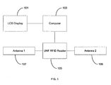
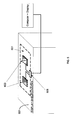
- FIG. 1 is a block diagram of an anti-theft RFID system in accordance with an embodiment of the present patent application.
- the system includes a display (a LCD display 101 in the illustrated embodiment), a processor (a computer 103 in the illustrated embodiment) connected to the LCD display 101, an RFID reader 105 connected to the computer 103, at least one antenna connected to the RFID reader 105, so that RFID tags proximate to the system can be detected.
- the RFID reader 105 is an ultra-high frequency (UHF) RFID Reader.
- the LCD display 101 may be a touch screen LCD display.
- the RFID reader 105 controlled by the computer 103, is configured to detect any RFID tags proximate thereto and interrogate the tags for retrieving data from the RFID tags.
- the RFID reader 105 is configured to send the data it retrieves from the RFID tags to the computer 103.
- the computer is configured to continuously monitor any change in the data.
- the anti-theft RFID system in this embodiment may be used in luxury shops. These shops typically do not prefer installing huge equipments and systems that are unmatched with the shop interior design. Therefore the anti-theft RFID system is designed in a way so that the whole setup is very small in size, which is feasible to lodge in the store in a hidden manner.
- the embodiment as illustrated in FIG. 1 can be seamlessly installed under the display shelves and fixed containers.
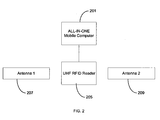
- FIG. 2 is a block diagram of an anti-theft RFID system used in a mobile environment in accordance with another embodiment of the present patent application.
- the display 101 and the processor 103 are embedded in an all-in-one mobile computer 201.
- the all-in-one mobile computer 201 includes a touch screen monitor.
- the whole setup should be able to operate with battery power supply or direct current (DC) power supply.
- This system can be lodged and embedded inside movable containers such as display trays, bins, boxes, etc.
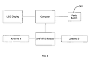
- FIG. 3 is a block diagram of an anti-theft RFID system with a panic button for security purpose in accordance with yet another embodiment of the present patent application.
- a predefined notification alert will be generated at the backend system when an operator determines a security event may have happened and presses the panic button 301.
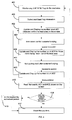
- FIG. 4 is a flow chart illustrating the operation of the anti-theft RFID systems as depicted in FIG. 1 and FIG. 2 .
- An RFID tag is used to store a unique product identifier for a merchandize item in a luxury store environment.
- the RFID reader (105 or 205) is used to detect and read the tag information so that the detected luxury item is recognized.
- Each item is associated with an RFID tag.
- the luxury items are put inside the display shelves. They are taken out for customer try-out upon request. Initially, when a customer wants to try out some items such as fine jewelry or watches at a luxury store, the store staff will put these items onto a tray or a fixed area.
- the system in the embodiment for a mobile environment as depicted in FIG. 2 is used in this illustration.
- the antennas (207 and 209) and the whole setup are embedded within a movable tray. The same system flow applies when the setup is installed in fixed display shelves.
- the antennas 207 and 209 installed in the tray are configured to monitor and detect the presence of the tagged items (Step 401). If the tag information is recognized, the RFID reader 205 will send the tag information to the computer 201 (Step 403).
- the computer 201 will update a counter (#C1) that is used to count the number of tagged merchandized items being detected over the tray, e.g. the total number of items on the tray in the beginning before any try-out (Step 405). This counter starts from zero and increases with the number of tagged merchandized items detected on the tray. The count is displayed on a touch-screen monitor included in the computer 201. During the trying out process, the item being tried out is taken out from the tray (Step 407).
- the system will detect that some RFID tagged items are out of the read area, i.e. the tray.
- the system will then update another counter (#C2) that is used to count the number of tagged merchandized items being taken out of the read area (Step 409). This count is also displayed in the small touch-screen monitor so as to give a clear comparison to the luxury store staff. This process continues while the customer tries out the items he/she likes. When the customer finishes trying out an item, the staff should put the item back onto the tray (Step 411).
- the counter (#C2) shall remove the details (RFID tag information) of the returned item or items from its counter value and display the updated counter value on the touch screen of the computer 201 (Step 413).
- Step 415 the store staff should read the counter values of both counters #C1 and #C2 (Step 415). If the counter #C2 reads zero (0), then it means that all items being try-out are safely and properly collected back onto the tray. The counters will then be reset by the store staff (Step 417). Otherwise if counter #C2 is not zero, there may be some items not yet collected by the store staff or a shoplifting may have already occurred. In the case of a non-zero counter #C2 value, an internal store authentication procedure will be carried out (Step 419). An authorized person is required to present his/her card, which is also RFID enabled, over the tray and let the system counters reset. Other approach in authentication procedure can be defined according to the store policy.
- Step 401, 403 and 405 will follow so that the counter #C1 will increase to reflect the new items being detected on the tray.
- Step 416 if the value of the counter #C1 does not match the store staff's expectation or #C2 is not zero (Step 416), then a security event may have occurred and an internal store authentication procedure will be carried out (Step 419). It is understood that such analysis on the counter values of #C1 and #C2 may be conducted by the store staff or automatically by the computer 201.
- system may be configured to provide a monitoring feature so that the counter numbers displayed on the screen can be remotely monitored by a remote computer.
- a remote computer can be used to monitor the actual happening in real time on every movable tray in the shop. The same monitoring feature applies when the setup is installed in fixed display shelves.
- FIG. 5 is a top view of an anti-theft RFID system in accordance with still another embodiment of the present patent application.
- FIG. 6 is a perspective view of the anti-theft RFID system depicted in FIG. 5.
- FIG. 5 and FIG. 6 illustrate the physical installation of the system setup when they are applied in the fixed container or display shelf.
- the luxury items are put on the display shelf or display counter before customer's trying out so that a defined area 501 on top of the display shelf can be assigned.
- This area 501 is a controlled area where the antennas and RFID reader are installed for detection of any tagged item being placed over there.
- the antennas and RFID reader are indeed embedded under the display shelf so that it is invisible to the customer. Any tagged item put in the controlled area 501 shall be detected by system.
- the computer and the display can be running in the same shelf counter area 501 or anywhere away from it.
- FIG. 6 illustrates the hiding of these setups and systems.
- the antennas 603 and the RFID reader 605 are hidden under the surface of display
- FIG. 7 is a top view of an anti-theft RFID system in accordance with still another embodiment of the present patent application.
- FIG. 8 is a perspective view of the anti-theft RFID system depicted in FIG. 7.
- FIG. 7 and FIG. 8 illustrate the physical installation of the system setup when they are applied in any movable containers, such as a tray in this embodiment.
- the antennas 701 are installed under the tray surface so that when the tagged items are put inside the tray, they are detected by the antennas connected to the RFID reader 703.
- An all-in-one touch screen computer 705 is lodged to operate the system and display the results to the store staff.
- FIG. 8 illustrates the perspective view of the tray with RFID devices installed. The antennas and the RFID reader are invisible from the outer appearance of the tray. The same design applies to all other movable containers.
- FIG. 9 is a block diagram of an anti-theft RFID system including a wireless charger adaptor for battery charging in accordance with still another embodiment of the present patent application.
- the system battery pack 903 can be recharged wirelessly by the wireless battery charger 901.
- the system should be able to operate under this battery power supply configuration with the battery power supply in the same way as in the aforementioned embodiments.
Description
- The present patent application generally relates to anti-theft technologies and more particularly to an anti-theft RFID system and a method thereof.
- Merchandise theft has reached a total of billions of US dollars every year. The amount of merchandise stolen by shoplifters and employees represents the majority of the total shrinkage. Therefore loss prevention can have its greatest impact by deterring would-be shoplifters and enabling merchandise recovery. Thieves tend to focus on small and easily-concealed, expensive, branded items that have considerable popular appeal and are easily re-sellable. Amongst the most vulnerable merchandise, small items such as branded watches and fine jewelry are always classified on the top few of the most attractive stolen products. There is no doubt that even a small single item being shoplifted in a luxury watch/jewelry shop will cost a big loss to the shop. It is absolutely intolerable of one case from happening. Unfortunately, even though significant innovations are taking place in the industry, there are not many new and effective solutions available today, spreading from comprehensive product protection strategies to state-of-the-art shrink management systems. In particular, holistic system approach in integrating shoplifting prevention into the branded item retailer work mode is rarely found in the market.
-
JP2007079615 -
US2007/0241865 discloses an information management system comprising a wireless IC tag and a wireless IC tag reader/writer. The wireless IC tag is provided with a counter. The information management system includes both the wireless IC tag and a wireless IC tag reader/writer. The system can be used to determine the integrity of the wireless IC tag and to identify the cause of a failure when the reader/writer fails to obtain information to/from the wireless IC tag. -
US2004/0111335 discloses a RFID space monitoring and asset inventory system. The system comprises radio frequency tags having RFID elements which are located in or on items situated in a given area of interest. The system further comprises an antenna which is automatically and virtually continuously moved around the proximity of the items to interrogate the presence of the items. When the RFID tags are interrogated by a RFID interrogation source, the source is quickly able to gain information as to the presence or absence of the item, and the identity of the item, for comparison to a database. Thus, inventory can be conducted continuously, which is particularly useful in the sale of high priced items. Thus, an operator can determine in real time what items are stored, sold, moved or displayed, etc., which greatly simplifies inventory assessments and aids in reducing theft.JP2001243564 -
US2003/0052788 discloses a medical assistance and tracking system and method employing smart tags. The system comprises a medication tracking and/or medical assistance device comprising a RFID tag coder for reading from and/or writing to a RFID tag. A processor and a memory process are also provided and information is read from the RFID tag to provide a reminder message based thereon by a visual and/or an audible reminder message. - The above documents disclose various systems and apparatus for monitoring the presence of items, in particular merchandise items, within a predefined area. However, these systems all relate to fixed displays or the specific tracking of the individual items themselves, thereby still making it difficult to track and/or cumbersome when being presented to and tried on by a customer.
- The present patent application is directed to a mobile tray for displaying a plurality of merchant items comprising an anti-theft RFID system for monitoring the presence of the items, each of the items being attached to an RFID tag. In one aspect, the anti-theft RFID system includes an RFID reader, the RFID reader including an antenna and being configured to transmit an interrogating signal to the RFID tags and retrieve data from the RFID tags through the antenna; a processor connected to the RFID reader and configured to process the data that the RFID reader retrieves from the RFID tags; and a display connected to the processor and configured to display a result processed by the processor. The processor is configured to update a first counter value indicating the number of tagged items located within a predefined area and to update a second counter value indicating the number of tagged items being taken away from the predefined area. The display is configured to display the values of the first and the second counters and thereby to assist an operator to determine the occurrence of a security event by analyzing the values of the first and the second counters; the RFID reader, the processor, the display and the antenna are embedded within the tray; the RFID reader and the antenna being arranged so as not to be visible from the exterior of the tray, and arranged so as to detect and monitor the presence of the items being displayed on the mobile tray.
- The processor and the display may be integrated into a mobile computer. The display may be a touch screen display. The anti-theft RFID system may further include a battery pack connected to the processor. The RFID reader, the processor and the display are powered by the battery pack. The anti-theft RFID system may further include a wireless battery charger connected to the battery pack. The wireless battery charger is configured to charge the battery pack wirelessly.
- The anti-theft RFID system may further include a panic button connected to the processor. The panic button is configured to be pushed by the operator when the operator determines a security event has occurred and thereby to trigger a predefined alert and a predetermined authentication procedure.
- The processor may be connected to a remote computer and monitored thereby. The processor may be configured to reset the first counter and the second counter after the operator determines no security event has occurred during a predefined session.
- In another aspect, the present patent application provides a method for detecting a security event for a plurality of merchant items using the above mobile tray, each of the items being attached to an RFID tag. The method includes transmitting an interrogating signal to the RFID tags and retrieving data from the RFID tags; processing the data retrieved from the RFID tags; and displaying a result of the processing. The step of processing the data retrieved from the RFID tags includes updating a first counter value indicating the number of tagged items located within a predefined area, updating a second counter value indicating the number of tagged items being taken away from the predefined area, and determining the occurrence of a security event by comparing the value of the first counter with an expected value and comparing the value of the second counter with zero.
- The method may further include generating a predefined alert and initiating a predetermined authentication procedure after determining a security event has occurred during a predefined session. The method may further include remotely and concurrently monitoring and processing the data retrieved from the RFID tags at multiple locations. The method may further include after determining no security event has occurred during a predefined session, resetting the first counter and the second counter.
- In yet another aspect, the present patent application provides an anti-theft RFID system for monitoring the presence of a plurality of tagged items, each of the tagged items being attached to an RFID tag. The anti-theft RFID system includes an RFID reader, the RFID reader including an antenna and being configured to transmit an interrogating signal to the RFID tags and retrieve data from the RFID tags through the antenna; a processor connected to the RFID reader and configured to process the data that the RFID reader retrieves from the RFID tags; and a display connected to the processor and configured to display a result processed by the processor. The processor is configured to update a first counter value indicating the number of tagged items located within a predefined area, to update a second counter value indicating the number of tagged items being taken away from the predefined area, to compare the value of the first counter with an expected value, and to compare the value of the second counter with zero so as to assist an operator to determine the occurrence of a security event. The display is configured to display the values of the first counter and the second counter.
-
-
FIG. 1 is a block diagram of an anti-theft RFID system in accordance with an embodiment of the present patent application. -
FIG. 2 is a block diagram of an anti-theft RFID system used in a mobile environment in accordance with another embodiment of the present patent application. -
FIG. 3 is a block diagram of an anti-theft RFID system with a panic button for security purpose in accordance with yet another embodiment of the present patent application. -
FIG. 4 is a flow chart illustrating the operation of the anti-theft RFID systems as depicted inFIG. 1 andFIG. 2 . -
FIG. 5 is a top view of an anti-theft RFID system in accordance with still another embodiment of the present patent application. -
FIG. 6 is a perspective view of the anti-theft RFID system depicted inFIG. 5 . -
FIG. 7 is a top view of an anti-theft RFID system in accordance with still another embodiment of the present patent application. -
FIG. 8 is a perspective view of the anti-theft RFID system depicted inFIG. 7 . -
FIG. 9 is a block diagram of an anti-theft RFID system including a wireless charger adaptor for battery charging in accordance with still another embodiment of the present patent application. - Reference will now be made in detail to a preferred embodiment of the anti-theft RFID system and the method thereof disclosed in the present patent application, examples of which are also provided in the following description. Exemplary embodiments of the anti-theft RFID system and the method thereof disclosed in the present patent application are described in detail, although it will be apparent to those skilled in the relevant art that some features that are not particularly important to an understanding of the anti-theft RFID system and the method thereof may not be shown for the sake of clarity.
- Furthermore, it should be understood that the anti-theft RFID system and the method thereof disclosed in the present patent application is not limited to the precise embodiments described below and that various changes and modifications thereof may be effected by one skilled in the art without departing from the spirit or scope of the protection. For example, elements and/or features of different illustrative embodiments may be combined with each other and/or substituted for each other within the scope of this disclosure.
-
FIG. 1 is a block diagram of an anti-theft RFID system in accordance with an embodiment of the present patent application. The system includes a display (aLCD display 101 in the illustrated embodiment), a processor (acomputer 103 in the illustrated embodiment) connected to theLCD display 101, anRFID reader 105 connected to thecomputer 103, at least one antenna connected to theRFID reader 105, so that RFID tags proximate to the system can be detected. In this embodiment, there are twoantennas RFID reader 105 to ensure the read area coverage. TheRFID reader 105 is an ultra-high frequency (UHF) RFID Reader. TheLCD display 101 may be a touch screen LCD display. - In operation, the
RFID reader 105, controlled by thecomputer 103, is configured to detect any RFID tags proximate thereto and interrogate the tags for retrieving data from the RFID tags. TheRFID reader 105 is configured to send the data it retrieves from the RFID tags to thecomputer 103. The computer is configured to continuously monitor any change in the data. - In general, the anti-theft RFID system in this embodiment may be used in luxury shops. These shops typically do not prefer installing huge equipments and systems that are unmatched with the shop interior design. Therefore the anti-theft RFID system is designed in a way so that the whole setup is very small in size, which is feasible to lodge in the store in a hidden manner. The embodiment as illustrated in
FIG. 1 can be seamlessly installed under the display shelves and fixed containers. -
FIG. 2 is a block diagram of an anti-theft RFID system used in a mobile environment in accordance with another embodiment of the present patent application. In this embodiment, thedisplay 101 and theprocessor 103 are embedded in an all-in-onemobile computer 201. In particular, the all-in-onemobile computer 201 includes a touch screen monitor. The whole setup should be able to operate with battery power supply or direct current (DC) power supply. This system can be lodged and embedded inside movable containers such as display trays, bins, boxes, etc. -
FIG. 3 is a block diagram of an anti-theft RFID system with a panic button for security purpose in accordance with yet another embodiment of the present patent application. In this embodiment, a predefined notification alert will be generated at the backend system when an operator determines a security event may have happened and presses thepanic button 301. -
FIG. 4 is a flow chart illustrating the operation of the anti-theft RFID systems as depicted inFIG. 1 andFIG. 2 . An RFID tag is used to store a unique product identifier for a merchandize item in a luxury store environment. The RFID reader (105 or 205) is used to detect and read the tag information so that the detected luxury item is recognized. Each item is associated with an RFID tag. - Usually the luxury items are put inside the display shelves. They are taken out for customer try-out upon request. Initially, when a customer wants to try out some items such as fine jewelry or watches at a luxury store, the store staff will put these items onto a tray or a fixed area. For simplicity, the system in the embodiment for a mobile environment as depicted in
FIG. 2 is used in this illustration. The antennas (207 and 209) and the whole setup are embedded within a movable tray. The same system flow applies when the setup is installed in fixed display shelves. - The
antennas RFID reader 205 will send the tag information to the computer 201 (Step 403). Thecomputer 201 will update a counter (#C1) that is used to count the number of tagged merchandized items being detected over the tray, e.g. the total number of items on the tray in the beginning before any try-out (Step 405). This counter starts from zero and increases with the number of tagged merchandized items detected on the tray. The count is displayed on a touch-screen monitor included in thecomputer 201. During the trying out process, the item being tried out is taken out from the tray (Step 407). Then the system will detect that some RFID tagged items are out of the read area, i.e. the tray. The system will then update another counter (#C2) that is used to count the number of tagged merchandized items being taken out of the read area (Step 409). This count is also displayed in the small touch-screen monitor so as to give a clear comparison to the luxury store staff. This process continues while the customer tries out the items he/she likes. When the customer finishes trying out an item, the staff should put the item back onto the tray (Step 411). The counter (#C2) shall remove the details (RFID tag information) of the returned item or items from its counter value and display the updated counter value on the touch screen of the computer 201 (Step 413). The process continues until the customer finishes trying out all preferred items. In the end, the store staff should read the counter values of both counters #C1 and #C2 (Step 415). If the counter #C2 reads zero (0), then it means that all items being try-out are safely and properly collected back onto the tray. The counters will then be reset by the store staff (Step 417). Otherwise if counter #C2 is not zero, there may be some items not yet collected by the store staff or a shoplifting may have already occurred. In the case of a non-zero counter #C2 value, an internal store authentication procedure will be carried out (Step 419). An authorized person is required to present his/her card, which is also RFID enabled, over the tray and let the system counters reset. Other approach in authentication procedure can be defined according to the store policy. - In the middle of the customer's trying out process, new items, which are not put onto and hence detected by the tray in the beginning, are allowed to put onto the tray anytime. The
aforementioned Step - In the above embodiment, if the value of the counter #C1 does not match the store staff's expectation or #C2 is not zero (Step 416), then a security event may have occurred and an internal store authentication procedure will be carried out (Step 419). It is understood that such analysis on the counter values of #C1 and #C2 may be conducted by the store staff or automatically by the
computer 201. - In addition, the system may be configured to provide a monitoring feature so that the counter numbers displayed on the screen can be remotely monitored by a remote computer. In other words, a centralized computer can be used to monitor the actual happening in real time on every movable tray in the shop. The same monitoring feature applies when the setup is installed in fixed display shelves.
-
FIG. 5 is a top view of an anti-theft RFID system in accordance with still another embodiment of the present patent application.FIG. 6 is a perspective view of the anti-theft RFID system depicted inFIG. 5. FIG. 5 andFIG. 6 illustrate the physical installation of the system setup when they are applied in the fixed container or display shelf. Referring toFIG. 5 , the luxury items are put on the display shelf or display counter before customer's trying out so that a definedarea 501 on top of the display shelf can be assigned. Thisarea 501 is a controlled area where the antennas and RFID reader are installed for detection of any tagged item being placed over there. The antennas and RFID reader are indeed embedded under the display shelf so that it is invisible to the customer. Any tagged item put in the controlledarea 501 shall be detected by system. The computer and the display can be running in the sameshelf counter area 501 or anywhere away from it.FIG. 6 illustrates the hiding of these setups and systems. Theantennas 603 and theRFID reader 605 are hidden under the surface of display shelf or thedisplay counter 607. -
FIG. 7 is a top view of an anti-theft RFID system in accordance with still another embodiment of the present patent application.FIG. 8 is a perspective view of the anti-theft RFID system depicted inFIG. 7. FIG. 7 andFIG. 8 illustrate the physical installation of the system setup when they are applied in any movable containers, such as a tray in this embodiment. Referring toFIG. 7 , theantennas 701 are installed under the tray surface so that when the tagged items are put inside the tray, they are detected by the antennas connected to theRFID reader 703. An all-in-onetouch screen computer 705 is lodged to operate the system and display the results to the store staff.FIG. 8 illustrates the perspective view of the tray with RFID devices installed. The antennas and the RFID reader are invisible from the outer appearance of the tray. The same design applies to all other movable containers. -
FIG. 9 is a block diagram of an anti-theft RFID system including a wireless charger adaptor for battery charging in accordance with still another embodiment of the present patent application. In this embodiment, thesystem battery pack 903 can be recharged wirelessly by thewireless battery charger 901. The system should be able to operate under this battery power supply configuration with the battery power supply in the same way as in the aforementioned embodiments. - While the present patent application has been shown and described with particular references to a number of embodiments thereof, it should be noted that various other changes or modifications may be made without departing from the scope of the present invention as defined by the following claims.
Claims (14)
- A mobile tray for displaying a plurality of merchant items comprising an anti-theft RFID system for monitoring the presence of the items, each of the items being attached to an RFID tag, the anti-theft RFID system comprising:an RFID reader (105, 205, 703), the RFID reader (105, 205, 703) comprising an antenna (107, 109, 207, 209, 701) and being configured to transmit an interrogating signal to the RFID tags and retrieve data from the RFID tags through the antenna (107, 109, 207, 209, 701);a processor (103) connected to the RFID reader (105, 205, 703) and configured to process the data that the RFID reader (105, 205, 703) retrieves from the RFID tags; anda display (101) connected to the processor (103) and configured to display a result processed by the processor (103); wherein:the processor (103) is configured to update a first counter value indicating the number of tagged items located within a predefined area and to update a second counter value indicating the number of tagged items being taken away from the predefined area; andthe display (101) is configured to display the values of the first and the second counters;characterised in that the RFID reader (105, 205, 703), the processor (103), the display (101) and the antenna (107, 109, 207, 209, 701) are embedded within the tray; the RFID reader (105, 205, 703) and the antenna (107, 109, 207, 209, 701) being arranged so as not to be visible from the exterior of the tray, and arranged so as to detect and monitor the presence of the items being displayed on the mobile tray.
- A mobile tray as claimed in claim 1, wherein the processor (103) and the display (101) are integrated into a mobile computer (201, 705).
- A mobile tray as claimed in claim 1, wherein the display (101) is a touch screen display.
- A mobile tray as claimed in claim 1, further comprising a battery pack (903) connected to the processor (103), wherein the RFID reader (105, 205, 703), the processor (103) and the display (101) are powered by the battery pack (903).
- A mobile tray as claimed in claim 4, further comprising a wireless battery charger (901) connected to the battery pack (903), wherein the wireless battery charger (901) is configured to charge the battery pack (903) wirelessly.
- A mobile tray as claimed in claim 1, further comprising a panic button (301) connected to the processor (103), wherein the panic button (301) is configured to be pushed by the operator when the operator determines a security event has occurred and thereby to trigger a predefined alert and a predetermined authentication procedure.
- A mobile tray as claimed in claim 1, wherein the processor (103) is connected to a remote computer and monitored thereby.
- A mobile tray as claimed in claim 1, wherein the processor (103) is configured to reset the first counter and the second counter after the operator determines no security event has occurred during a predefined session.
- A mobile tray as claimed in claim 1, wherein the processor (103) is further configured to compare the value of the first counter with an expected value, and to compare the value of the second counter with zero so as to assist an operator to determine the occurrence of a security event.
- A mobile tray as claimed in claim 1, wherein the display (101) assist an operator to determine the occurrence of a security event by analyzing the values of the first and the second counters.
- A method for detecting a security event for a plurality of merchant items using the mobile tray as claimed in any one of claims 1 to 10, each of the items being attached to an RFID tag, the method comprising:transmitting an interrogating signal to the RFID tags and retrieving data from the RFID tags;processing the data retrieved from the RFID tags; anddisplaying a result of the processing; wherein:the step of processing the data retrieved from the RFID tags comprises updating a first counter value indicating the number of tagged items located within a predefined area, updating a second counter value indicating the number of tagged items being taken away from the predefined area, and determining the occurrence of a security event by comparing the value of the first counter with an expected value and comparing the value of the second counter with zero.
- A method as claimed in claim 11, further comprising generating a predefined alert and initiating a predetermined authentication procedure after determining a security event has occurred during a predefined session.
- A method as claimed in claim 11, further comprising remotely and concurrently monitoring and processing the data retrieved from the RFID tags at multiple locations.
- A method as claimed in claim 11, further comprising after determining no security event has occurred during a predefined session, resetting the first counter and the second counter.
Applications Claiming Priority (2)
| Application Number | Priority Date | Filing Date | Title |
|---|---|---|---|
| US26467209P | 2009-11-26 | 2009-11-26 | |
| PCT/CN2010/077728 WO2011063686A1 (en) | 2009-11-26 | 2010-10-14 | Anti-theft rfid system and method thereof |
Publications (3)
| Publication Number | Publication Date |
|---|---|
| EP2504823A1 EP2504823A1 (en) | 2012-10-03 |
| EP2504823A4 EP2504823A4 (en) | 2012-12-19 |
| EP2504823B1 true EP2504823B1 (en) | 2014-10-01 |
Family
ID=43243641
Family Applications (1)
| Application Number | Title | Priority Date | Filing Date |
|---|---|---|---|
| EP10832593.7A Active EP2504823B1 (en) | 2009-11-26 | 2010-10-14 | Anti-theft rfid system and method thereof |
Country Status (7)
| Country | Link |
|---|---|
| US (1) | US20130135105A1 (en) |
| EP (1) | EP2504823B1 (en) |
| CN (2) | CN201892998U (en) |
| GB (1) | GB2475755B (en) |
| HK (6) | HK1146619A2 (en) |
| TW (1) | TWM407452U (en) |
| WO (1) | WO2011063686A1 (en) |
Cited By (1)
| Publication number | Priority date | Publication date | Assignee | Title |
|---|---|---|---|---|
| US11681815B2 (en) | 2018-06-22 | 2023-06-20 | Vault Security Systems Ag | Secure tracking of items utilizing distributed computing |
Families Citing this family (9)
| Publication number | Priority date | Publication date | Assignee | Title |
|---|---|---|---|---|
| KR101338732B1 (en) | 2011-11-10 | 2013-12-06 | 엘지이노텍 주식회사 | Apparatus for transmmiting wireless power and apparatus for receiving wireless power and method for transmitting wireless power, method for receiving wireless power, method for transmitting information and method for receiving information |
| DE102013110168B4 (en) * | 2013-09-16 | 2017-04-13 | micronex GmbH | ESD protection element with structurally integrated RFID antenna |
| TWI533151B (en) | 2013-09-23 | 2016-05-11 | 周大福珠寶金行有限公司 | Presentation apparatus |
| MY179753A (en) * | 2013-09-23 | 2020-11-12 | Chow Tai Fook Jewellery Co Ltd | Presentation apparatus (iot) |
| CN103593935A (en) * | 2013-10-25 | 2014-02-19 | 北京华鑫杰瑞计算机系统工程有限公司 | Wireless label device for guaranteeing safety of important object |
| CN106714612B (en) * | 2014-05-30 | 2020-08-11 | 电子商品交易合伙人有限公司 | RFID enhancements and location detection in jewelry shopping experiences |
| US10061951B2 (en) * | 2016-11-30 | 2018-08-28 | Wipro Limited | Methods and systems for localizing articles comprising passive radio frequency identification (RFID) tags |
| CN110366441B (en) | 2017-03-06 | 2022-06-28 | 康明斯滤清系统知识产权公司 | Genuine filter identification with filter monitoring system |
| GB201901066D0 (en) * | 2019-01-25 | 2019-03-13 | Nicoventures Trading Ltd | Aerosol generating apparatus, aerosol generating article and method of determining data associated with an aerosol generating article |
Family Cites Families (15)
| Publication number | Priority date | Publication date | Assignee | Title |
|---|---|---|---|---|
| US6294999B1 (en) * | 1999-12-29 | 2001-09-25 | Becton, Dickinson And Company | Systems and methods for monitoring patient compliance with medication regimens |
| JP2001243564A (en) | 2000-03-02 | 2001-09-07 | Morimoto Shoten Kk | Jewel robbery monitoring device |
| US7158030B2 (en) * | 2001-09-19 | 2007-01-02 | Avante International Technology | Medical assistance and tracking system and method employing smart tags |
| US7471062B2 (en) * | 2002-06-12 | 2008-12-30 | Koninklijke Philips Electronics N.V. | Wireless battery charging |
| US20040111335A1 (en) * | 2002-12-04 | 2004-06-10 | Black Charles Ronald | RFID space monitoring and asset inventory system |
| US7583178B2 (en) * | 2005-03-16 | 2009-09-01 | Datalogic Mobile, Inc. | System and method for RFID reader operation |
| US7362228B2 (en) * | 2005-04-28 | 2008-04-22 | Warsaw Orthepedic, Inc. | Smart instrument tray RFID reader |
| US20070040682A1 (en) * | 2005-08-22 | 2007-02-22 | Mark Iv Industries Corp. | RFID inventory control system |
| JP2007079615A (en) * | 2005-09-09 | 2007-03-29 | Toshiba Tec Corp | Merchandise management system |
| US7757947B2 (en) * | 2006-03-17 | 2010-07-20 | Siemens Aktiengesellschaft | R.F.I.D. enabled storage bin and method for tracking inventory |
| CN101046851A (en) * | 2006-03-31 | 2007-10-03 | 日本电气株式会社 | Wireless IC tag with counter, and information management system |
| US8391375B2 (en) * | 2006-05-05 | 2013-03-05 | University of Pittsburgh—of the Commonwealth System of Higher Education | Wireless autonomous device data transmission |
| US8040221B2 (en) * | 2007-05-02 | 2011-10-18 | The Boeing Company | Mobile radio frequency identification reader |
| US20090058595A1 (en) * | 2007-08-30 | 2009-03-05 | Atmel Corporation | Biometric Control Device |
| US8020768B2 (en) * | 2009-04-01 | 2011-09-20 | RFID Mexico, S.A. DE C.V. | Portable container inventory control system |
-
2010
- 2010-10-07 GB GB1016871.4A patent/GB2475755B/en active Active
- 2010-10-14 EP EP10832593.7A patent/EP2504823B1/en active Active
- 2010-10-14 WO PCT/CN2010/077728 patent/WO2011063686A1/en active Application Filing
- 2010-10-21 HK HK11100597.4A patent/HK1146619A2/en not_active IP Right Cessation
- 2010-10-21 HK HK11100596.5A patent/HK1146618A2/en not_active IP Right Cessation
- 2010-10-21 HK HK10109981.0A patent/HK1144750A2/en not_active IP Right Cessation
- 2010-10-28 CN CN201020596647.2U patent/CN201892998U/en not_active Expired - Lifetime
- 2010-10-28 TW TW099220811U patent/TWM407452U/en not_active IP Right Cessation
- 2010-10-28 CN CN201010539301.3A patent/CN102081830B/en active Active
-
2011
- 2011-06-16 HK HK11106225.1A patent/HK1153566A1/en unknown
- 2011-11-22 HK HK11112641.5A patent/HK1159293A1/en unknown
-
2012
- 2012-05-24 US US13/479,286 patent/US20130135105A1/en not_active Abandoned
- 2012-11-09 HK HK12111391.8A patent/HK1170836A1/en unknown
Cited By (1)
| Publication number | Priority date | Publication date | Assignee | Title |
|---|---|---|---|---|
| US11681815B2 (en) | 2018-06-22 | 2023-06-20 | Vault Security Systems Ag | Secure tracking of items utilizing distributed computing |
Also Published As
| Publication number | Publication date |
|---|---|
| GB201016871D0 (en) | 2010-11-17 |
| HK1146618A2 (en) | 2011-06-24 |
| GB2475755A (en) | 2011-06-01 |
| WO2011063686A1 (en) | 2011-06-03 |
| HK1170836A1 (en) | 2013-03-08 |
| HK1153566A1 (en) | 2012-03-30 |
| HK1144750A2 (en) | 2011-03-04 |
| GB2475755B (en) | 2012-01-11 |
| HK1159293A1 (en) | 2012-07-27 |
| US20130135105A1 (en) | 2013-05-30 |
| CN102081830A (en) | 2011-06-01 |
| CN201892998U (en) | 2011-07-06 |
| HK1146619A2 (en) | 2011-06-24 |
| EP2504823A4 (en) | 2012-12-19 |
| EP2504823A1 (en) | 2012-10-03 |
| CN102081830B (en) | 2016-05-11 |
| TWM407452U (en) | 2011-07-11 |
Similar Documents
| Publication | Publication Date | Title |
|---|---|---|
| EP2504823B1 (en) | Anti-theft rfid system and method thereof | |
| US10636267B2 (en) | RFID tag tracking systems and methods in identifying suspicious activities | |
| KR100497558B1 (en) | Electronic article security system for store which uses intelligent security tags and transaction data | |
| US20160239796A1 (en) | System and method for monitoring merchandise in a retail environment | |
| EP2759975B1 (en) | Tag system, sellable item and method for facilitating the purchase of a sellable item | |
| EP2686810B1 (en) | System and method for identifying groups of rfid tags | |
| MX2007009644A (en) | Alarm investigation using rfid. | |
| CN103975370A (en) | Video enabled electronic article surveillance detection system and method | |
| US20140225734A1 (en) | Inhibiting alarming of an electronic article surviellance system | |
| US10229568B2 (en) | Anti-theft RFID system and method thereof | |
| EP4038593A1 (en) | Validating radio frequency identification (rfid) alarm event tags | |
| EP2304702B1 (en) | Electronic article surveillance deactivator with multiple label detection and method thereof | |
| US20220067635A1 (en) | Inventory tracking systems and methods | |
| JP2011065453A (en) | System for investigating degree of interest | |
| MXPA99002405A (en) | Electronic article security system for store which uses intelligent security tags and transaction data |
Legal Events
| Date | Code | Title | Description |
|---|---|---|---|
| PUAI | Public reference made under article 153(3) epc to a published international application that has entered the european phase |
Free format text: ORIGINAL CODE: 0009012 |
|
| 17P | Request for examination filed |
Effective date: 20120516 |
|
| AK | Designated contracting states |
Kind code of ref document: A1 Designated state(s): AL AT BE BG CH CY CZ DE DK EE ES FI FR GB GR HR HU IE IS IT LI LT LU LV MC MK MT NL NO PL PT RO RS SE SI SK SM TR |
|
| A4 | Supplementary search report drawn up and despatched |
Effective date: 20121116 |
|
| RIC1 | Information provided on ipc code assigned before grant |
Ipc: G06Q 10/00 20120101ALI20121112BHEP Ipc: G08B 13/24 20060101ALI20121112BHEP Ipc: G08B 21/02 20060101ALI20121112BHEP Ipc: G08B 13/14 20060101AFI20121112BHEP Ipc: G06K 7/00 20060101ALI20121112BHEP |
|
| 17Q | First examination report despatched |
Effective date: 20121210 |
|
| DAX | Request for extension of the european patent (deleted) | ||
| REG | Reference to a national code |
Ref country code: HK Ref legal event code: DE Ref document number: 1170836 Country of ref document: HK |
|
| GRAP | Despatch of communication of intention to grant a patent |
Free format text: ORIGINAL CODE: EPIDOSNIGR1 |
|
| INTG | Intention to grant announced |
Effective date: 20140422 |
|
| GRAS | Grant fee paid |
Free format text: ORIGINAL CODE: EPIDOSNIGR3 |
|
| GRAA | (expected) grant |
Free format text: ORIGINAL CODE: 0009210 |
|
| AK | Designated contracting states |
Kind code of ref document: B1 Designated state(s): AL AT BE BG CH CY CZ DE DK EE ES FI FR GB GR HR HU IE IS IT LI LT LU LV MC MK MT NL NO PL PT RO RS SE SI SK SM TR |
|
| REG | Reference to a national code |
Ref country code: GB Ref legal event code: FG4D |
|
| REG | Reference to a national code |
Ref country code: CH Ref legal event code: EP Ref country code: AT Ref legal event code: REF Ref document number: 689856 Country of ref document: AT Kind code of ref document: T Effective date: 20141015 |
|
| REG | Reference to a national code |
Ref country code: IE Ref legal event code: FG4D |
|
| REG | Reference to a national code |
Ref country code: DE Ref legal event code: R096 Ref document number: 602010019312 Country of ref document: DE Effective date: 20141113 |
|
| REG | Reference to a national code |
Ref country code: HK Ref legal event code: GR Ref document number: 1170836 Country of ref document: HK |
|
| REG | Reference to a national code |
Ref country code: NL Ref legal event code: VDEP Effective date: 20141001 |
|
| REG | Reference to a national code |
Ref country code: AT Ref legal event code: MK05 Ref document number: 689856 Country of ref document: AT Kind code of ref document: T Effective date: 20141001 |
|
| REG | Reference to a national code |
Ref country code: LT Ref legal event code: MG4D |
|
| PG25 | Lapsed in a contracting state [announced via postgrant information from national office to epo] |
Ref country code: NL Free format text: LAPSE BECAUSE OF FAILURE TO SUBMIT A TRANSLATION OF THE DESCRIPTION OR TO PAY THE FEE WITHIN THE PRESCRIBED TIME-LIMIT Effective date: 20141001 |
|
| PG25 | Lapsed in a contracting state [announced via postgrant information from national office to epo] |
Ref country code: ES Free format text: LAPSE BECAUSE OF FAILURE TO SUBMIT A TRANSLATION OF THE DESCRIPTION OR TO PAY THE FEE WITHIN THE PRESCRIBED TIME-LIMIT Effective date: 20141001 Ref country code: LT Free format text: LAPSE BECAUSE OF FAILURE TO SUBMIT A TRANSLATION OF THE DESCRIPTION OR TO PAY THE FEE WITHIN THE PRESCRIBED TIME-LIMIT Effective date: 20141001 Ref country code: NO Free format text: LAPSE BECAUSE OF FAILURE TO SUBMIT A TRANSLATION OF THE DESCRIPTION OR TO PAY THE FEE WITHIN THE PRESCRIBED TIME-LIMIT Effective date: 20150101 Ref country code: PT Free format text: LAPSE BECAUSE OF FAILURE TO SUBMIT A TRANSLATION OF THE DESCRIPTION OR TO PAY THE FEE WITHIN THE PRESCRIBED TIME-LIMIT Effective date: 20150202 Ref country code: CZ Free format text: LAPSE BECAUSE OF FAILURE TO SUBMIT A TRANSLATION OF THE DESCRIPTION OR TO PAY THE FEE WITHIN THE PRESCRIBED TIME-LIMIT Effective date: 20141001 Ref country code: IS Free format text: LAPSE BECAUSE OF FAILURE TO SUBMIT A TRANSLATION OF THE DESCRIPTION OR TO PAY THE FEE WITHIN THE PRESCRIBED TIME-LIMIT Effective date: 20150201 Ref country code: FI Free format text: LAPSE BECAUSE OF FAILURE TO SUBMIT A TRANSLATION OF THE DESCRIPTION OR TO PAY THE FEE WITHIN THE PRESCRIBED TIME-LIMIT Effective date: 20141001 |
|
| PG25 | Lapsed in a contracting state [announced via postgrant information from national office to epo] |
Ref country code: CY Free format text: LAPSE BECAUSE OF FAILURE TO SUBMIT A TRANSLATION OF THE DESCRIPTION OR TO PAY THE FEE WITHIN THE PRESCRIBED TIME-LIMIT Effective date: 20141001 Ref country code: PL Free format text: LAPSE BECAUSE OF FAILURE TO SUBMIT A TRANSLATION OF THE DESCRIPTION OR TO PAY THE FEE WITHIN THE PRESCRIBED TIME-LIMIT Effective date: 20141001 Ref country code: SE Free format text: LAPSE BECAUSE OF FAILURE TO SUBMIT A TRANSLATION OF THE DESCRIPTION OR TO PAY THE FEE WITHIN THE PRESCRIBED TIME-LIMIT Effective date: 20141001 Ref country code: AT Free format text: LAPSE BECAUSE OF FAILURE TO SUBMIT A TRANSLATION OF THE DESCRIPTION OR TO PAY THE FEE WITHIN THE PRESCRIBED TIME-LIMIT Effective date: 20141001 Ref country code: GR Free format text: LAPSE BECAUSE OF FAILURE TO SUBMIT A TRANSLATION OF THE DESCRIPTION OR TO PAY THE FEE WITHIN THE PRESCRIBED TIME-LIMIT Effective date: 20150102 Ref country code: HR Free format text: LAPSE BECAUSE OF FAILURE TO SUBMIT A TRANSLATION OF THE DESCRIPTION OR TO PAY THE FEE WITHIN THE PRESCRIBED TIME-LIMIT Effective date: 20141001 Ref country code: RS Free format text: LAPSE BECAUSE OF FAILURE TO SUBMIT A TRANSLATION OF THE DESCRIPTION OR TO PAY THE FEE WITHIN THE PRESCRIBED TIME-LIMIT Effective date: 20141001 Ref country code: LV Free format text: LAPSE BECAUSE OF FAILURE TO SUBMIT A TRANSLATION OF THE DESCRIPTION OR TO PAY THE FEE WITHIN THE PRESCRIBED TIME-LIMIT Effective date: 20141001 |
|
| PG25 | Lapsed in a contracting state [announced via postgrant information from national office to epo] |
Ref country code: MC Free format text: LAPSE BECAUSE OF FAILURE TO SUBMIT A TRANSLATION OF THE DESCRIPTION OR TO PAY THE FEE WITHIN THE PRESCRIBED TIME-LIMIT Effective date: 20141001 Ref country code: BE Free format text: LAPSE BECAUSE OF NON-PAYMENT OF DUE FEES Effective date: 20141031 |
|
| REG | Reference to a national code |
Ref country code: DE Ref legal event code: R097 Ref document number: 602010019312 Country of ref document: DE |
|
| REG | Reference to a national code |
Ref country code: IE Ref legal event code: MM4A |
|
| PG25 | Lapsed in a contracting state [announced via postgrant information from national office to epo] |
Ref country code: SK Free format text: LAPSE BECAUSE OF FAILURE TO SUBMIT A TRANSLATION OF THE DESCRIPTION OR TO PAY THE FEE WITHIN THE PRESCRIBED TIME-LIMIT Effective date: 20141001 Ref country code: EE Free format text: LAPSE BECAUSE OF FAILURE TO SUBMIT A TRANSLATION OF THE DESCRIPTION OR TO PAY THE FEE WITHIN THE PRESCRIBED TIME-LIMIT Effective date: 20141001 Ref country code: RO Free format text: LAPSE BECAUSE OF FAILURE TO SUBMIT A TRANSLATION OF THE DESCRIPTION OR TO PAY THE FEE WITHIN THE PRESCRIBED TIME-LIMIT Effective date: 20141001 Ref country code: DK Free format text: LAPSE BECAUSE OF FAILURE TO SUBMIT A TRANSLATION OF THE DESCRIPTION OR TO PAY THE FEE WITHIN THE PRESCRIBED TIME-LIMIT Effective date: 20141001 |
|
| PLBE | No opposition filed within time limit |
Free format text: ORIGINAL CODE: 0009261 |
|
| STAA | Information on the status of an ep patent application or granted ep patent |
Free format text: STATUS: NO OPPOSITION FILED WITHIN TIME LIMIT |
|
| PG25 | Lapsed in a contracting state [announced via postgrant information from national office to epo] |
Ref country code: IT Free format text: LAPSE BECAUSE OF FAILURE TO SUBMIT A TRANSLATION OF THE DESCRIPTION OR TO PAY THE FEE WITHIN THE PRESCRIBED TIME-LIMIT Effective date: 20141001 |
|
| 26N | No opposition filed |
Effective date: 20150702 |
|
| REG | Reference to a national code |
Ref country code: FR Ref legal event code: ST Effective date: 20150807 |
|
| PG25 | Lapsed in a contracting state [announced via postgrant information from national office to epo] |
Ref country code: IE Free format text: LAPSE BECAUSE OF NON-PAYMENT OF DUE FEES Effective date: 20141014 |
|
| PG25 | Lapsed in a contracting state [announced via postgrant information from national office to epo] |
Ref country code: FR Free format text: LAPSE BECAUSE OF NON-PAYMENT OF DUE FEES Effective date: 20141201 |
|
| PG25 | Lapsed in a contracting state [announced via postgrant information from national office to epo] |
Ref country code: SI Free format text: LAPSE BECAUSE OF FAILURE TO SUBMIT A TRANSLATION OF THE DESCRIPTION OR TO PAY THE FEE WITHIN THE PRESCRIBED TIME-LIMIT Effective date: 20141001 |
|
| PG25 | Lapsed in a contracting state [announced via postgrant information from national office to epo] |
Ref country code: SM Free format text: LAPSE BECAUSE OF FAILURE TO SUBMIT A TRANSLATION OF THE DESCRIPTION OR TO PAY THE FEE WITHIN THE PRESCRIBED TIME-LIMIT Effective date: 20141001 |
|
| PG25 | Lapsed in a contracting state [announced via postgrant information from national office to epo] |
Ref country code: BG Free format text: LAPSE BECAUSE OF FAILURE TO SUBMIT A TRANSLATION OF THE DESCRIPTION OR TO PAY THE FEE WITHIN THE PRESCRIBED TIME-LIMIT Effective date: 20141001 |
|
| PG25 | Lapsed in a contracting state [announced via postgrant information from national office to epo] |
Ref country code: TR Free format text: LAPSE BECAUSE OF FAILURE TO SUBMIT A TRANSLATION OF THE DESCRIPTION OR TO PAY THE FEE WITHIN THE PRESCRIBED TIME-LIMIT Effective date: 20141001 Ref country code: LU Free format text: LAPSE BECAUSE OF NON-PAYMENT OF DUE FEES Effective date: 20141014 Ref country code: MT Free format text: LAPSE BECAUSE OF FAILURE TO SUBMIT A TRANSLATION OF THE DESCRIPTION OR TO PAY THE FEE WITHIN THE PRESCRIBED TIME-LIMIT Effective date: 20141001 Ref country code: HU Free format text: LAPSE BECAUSE OF FAILURE TO SUBMIT A TRANSLATION OF THE DESCRIPTION OR TO PAY THE FEE WITHIN THE PRESCRIBED TIME-LIMIT; INVALID AB INITIO Effective date: 20101014 |
|
| PG25 | Lapsed in a contracting state [announced via postgrant information from national office to epo] |
Ref country code: MK Free format text: LAPSE BECAUSE OF FAILURE TO SUBMIT A TRANSLATION OF THE DESCRIPTION OR TO PAY THE FEE WITHIN THE PRESCRIBED TIME-LIMIT Effective date: 20141001 |
|
| PG25 | Lapsed in a contracting state [announced via postgrant information from national office to epo] |
Ref country code: AL Free format text: LAPSE BECAUSE OF FAILURE TO SUBMIT A TRANSLATION OF THE DESCRIPTION OR TO PAY THE FEE WITHIN THE PRESCRIBED TIME-LIMIT Effective date: 20141001 |
|
| PGFP | Annual fee paid to national office [announced via postgrant information from national office to epo] |
Ref country code: GB Payment date: 20231020 Year of fee payment: 14 |
|
| PGFP | Annual fee paid to national office [announced via postgrant information from national office to epo] |
Ref country code: DE Payment date: 20231020 Year of fee payment: 14 Ref country code: CH Payment date: 20231102 Year of fee payment: 14 |