EP2503438A2 - Mobile terminal and control method thereof - Google Patents
Mobile terminal and control method thereof Download PDFInfo
- Publication number
- EP2503438A2 EP2503438A2 EP11007902A EP11007902A EP2503438A2 EP 2503438 A2 EP2503438 A2 EP 2503438A2 EP 11007902 A EP11007902 A EP 11007902A EP 11007902 A EP11007902 A EP 11007902A EP 2503438 A2 EP2503438 A2 EP 2503438A2
- Authority
- EP
- European Patent Office
- Prior art keywords
- detection target
- mobile terminal
- location
- movement
- stereoscopic image
- Prior art date
- Legal status (The legal status is an assumption and is not a legal conclusion. Google has not performed a legal analysis and makes no representation as to the accuracy of the status listed.)
- Granted
Links
Images


Classifications
-
- G—PHYSICS
- G06—COMPUTING; CALCULATING OR COUNTING
- G06F—ELECTRIC DIGITAL DATA PROCESSING
- G06F3/00—Input arrangements for transferring data to be processed into a form capable of being handled by the computer; Output arrangements for transferring data from processing unit to output unit, e.g. interface arrangements
- G06F3/01—Input arrangements or combined input and output arrangements for interaction between user and computer
- G06F3/03—Arrangements for converting the position or the displacement of a member into a coded form
-
- G—PHYSICS
- G06—COMPUTING; CALCULATING OR COUNTING
- G06F—ELECTRIC DIGITAL DATA PROCESSING
- G06F3/00—Input arrangements for transferring data to be processed into a form capable of being handled by the computer; Output arrangements for transferring data from processing unit to output unit, e.g. interface arrangements
- G06F3/01—Input arrangements or combined input and output arrangements for interaction between user and computer
- G06F3/048—Interaction techniques based on graphical user interfaces [GUI]
- G06F3/0487—Interaction techniques based on graphical user interfaces [GUI] using specific features provided by the input device, e.g. functions controlled by the rotation of a mouse with dual sensing arrangements, or of the nature of the input device, e.g. tap gestures based on pressure sensed by a digitiser
- G06F3/0488—Interaction techniques based on graphical user interfaces [GUI] using specific features provided by the input device, e.g. functions controlled by the rotation of a mouse with dual sensing arrangements, or of the nature of the input device, e.g. tap gestures based on pressure sensed by a digitiser using a touch-screen or digitiser, e.g. input of commands through traced gestures
-
- G—PHYSICS
- G06—COMPUTING; CALCULATING OR COUNTING
- G06F—ELECTRIC DIGITAL DATA PROCESSING
- G06F3/00—Input arrangements for transferring data to be processed into a form capable of being handled by the computer; Output arrangements for transferring data from processing unit to output unit, e.g. interface arrangements
- G06F3/01—Input arrangements or combined input and output arrangements for interaction between user and computer
- G06F3/016—Input arrangements with force or tactile feedback as computer generated output to the user
-
- G—PHYSICS
- G06—COMPUTING; CALCULATING OR COUNTING
- G06F—ELECTRIC DIGITAL DATA PROCESSING
- G06F3/00—Input arrangements for transferring data to be processed into a form capable of being handled by the computer; Output arrangements for transferring data from processing unit to output unit, e.g. interface arrangements
- G06F3/01—Input arrangements or combined input and output arrangements for interaction between user and computer
- G06F3/048—Interaction techniques based on graphical user interfaces [GUI]
- G06F3/0481—Interaction techniques based on graphical user interfaces [GUI] based on specific properties of the displayed interaction object or a metaphor-based environment, e.g. interaction with desktop elements like windows or icons, or assisted by a cursor's changing behaviour or appearance
- G06F3/04815—Interaction with a metaphor-based environment or interaction object displayed as three-dimensional, e.g. changing the user viewpoint with respect to the environment or object
-
- G—PHYSICS
- G06—COMPUTING; CALCULATING OR COUNTING
- G06F—ELECTRIC DIGITAL DATA PROCESSING
- G06F3/00—Input arrangements for transferring data to be processed into a form capable of being handled by the computer; Output arrangements for transferring data from processing unit to output unit, e.g. interface arrangements
- G06F3/01—Input arrangements or combined input and output arrangements for interaction between user and computer
- G06F3/048—Interaction techniques based on graphical user interfaces [GUI]
- G06F3/0484—Interaction techniques based on graphical user interfaces [GUI] for the control of specific functions or operations, e.g. selecting or manipulating an object, an image or a displayed text element, setting a parameter value or selecting a range
-
- H—ELECTRICITY
- H04—ELECTRIC COMMUNICATION TECHNIQUE
- H04B—TRANSMISSION
- H04B1/00—Details of transmission systems, not covered by a single one of groups H04B3/00 - H04B13/00; Details of transmission systems not characterised by the medium used for transmission
- H04B1/38—Transceivers, i.e. devices in which transmitter and receiver form a structural unit and in which at least one part is used for functions of transmitting and receiving
- H04B1/40—Circuits
-
- G—PHYSICS
- G06—COMPUTING; CALCULATING OR COUNTING
- G06F—ELECTRIC DIGITAL DATA PROCESSING
- G06F2203/00—Indexing scheme relating to G06F3/00 - G06F3/048
- G06F2203/048—Indexing scheme relating to G06F3/048
- G06F2203/04808—Several contacts: gestures triggering a specific function, e.g. scrolling, zooming, right-click, when the user establishes several contacts with the surface simultaneously; e.g. using several fingers or a combination of fingers and pen
Landscapes
- Engineering & Computer Science (AREA)
- General Engineering & Computer Science (AREA)
- Theoretical Computer Science (AREA)
- Human Computer Interaction (AREA)
- Physics & Mathematics (AREA)
- General Physics & Mathematics (AREA)
- Computer Networks & Wireless Communication (AREA)
- Signal Processing (AREA)
- User Interface Of Digital Computer (AREA)
- Telephone Function (AREA)
- Position Input By Displaying (AREA)
Abstract
Description
- The present disclosure relates to a mobile terminal, and more particularly, to a mobile terminal and control method thereof for allowing a touch input to a three-dimensional stereoscopic image.
- Terminals can be classified into a mobile terminal and a stationary terminal based on its mobility. Furthermore, terminals can be further classified into a handheld terminal and a vehicle mount terminal based on whether or not it can be directly carried by a user.
- As it becomes multifunctional, the mobile terminal can be allowed to capture still or moving images, play music or video files, play games, receive broadcast and the like, so as to be implemented as an integrated multimedia player. Moreover, in order to support and enhance the function of the terminal, the improvement of the terminal may be considered in the aspect of structure or software.
- Owing to the improvement, terminals have evolved above the level of displaying two-dimensional stereoscopic images to display three-dimensional stereoscopic images allowing depth perception or stereovision. As a result, a user can enjoy more realistic user interfaces or contents through three-dimensional stereoscopic images.
- An object of the present invention is to provide a mobile terminal and control method thereof capable of controlling objects using a distance change between the objects displayed on a three-dimensional stereoscopic image.
- In addition, another object of the present invention is to provide a mobile terminal and control method thereof capable of enhance the user's convenience n controlling objects displayed on a three-dimensional stereoscopic image.
- A method of controlling a mobile terminal according to an embodiment of the present invention may include displaying a three-dimensional stereoscopic image including a plurality of objects, detecting the location of a detection target in a detection region corresponding to the three-dimensional stereoscopic image, selecting a first object based on the location of the detection target, moving the first object along the movement of the detection target in a state that the first object is selected, and generating at least one object between the first and the second object when a distance between the first and the second object is increased in one direction due to the movement of the first object.
- The method of controlling a mobile terminal may further include deleting at least one of objects displayed between the first and the second object when a distance between the first and the second object is decreased in one direction due to the movement of the first object.
- The number of objects generated or deleted between the first and the second object may be determined by a changed distance between the first and the second object. The one direction may be a vertical direction with respect to a display unit for outputting the three-dimensional stereoscopic image.
- The method of controlling a mobile terminal may further include changing the location of objects displayed between first and the second object to the other direction when a distance between the first and the second object is changed to the other direction perpendicular to the one direction.
- The method of controlling a mobile terminal may further include selecting a third object based on the location of the detection target, moving the first and the third object along the movement of the detection target in a state that the first and the third object are selected, and generating at least one object between the first and the third object when a distance between the first and the third object is increased in one direction due to the movement of the first and the third object.
- The method of controlling a mobile terminal may further include selecting a fourth object generated between the first and the second object based on the location of the detection target, and controlling the fourth object in a state that the fourth object is selected.
- Said controlling the fourth object may include displaying a control menu associated with the fourth object, and adding a fifth object corresponding to selection information entered by using the control menu to the fourth object. Said controlling the fourth object may include deleting the fourth object in response to a delete command entered by the detection target.
- The method of controlling a mobile terminal may further include changing the location of at least one of the remaining objects when the fourth object is deleted. Furthermore, the method of controlling a mobile terminal may further include generating a sixth object substituting the fourth object in a vacant region between the first and the second object when the fourth object is deleted.
- Said controlling the fourth object may include moving the fourth object between the first and the second object along the movement of the detection target.
- The method of controlling a mobile terminal may further include changing the location of at least one object displayed between the first and the second object when the fourth object is moved.
- Said controlling the fourth object may include performing an editing operation using a clipboard when the fourth object includes the clipboard. Said controlling the fourth object may include displaying and storing data entered by using a virtual keyboard in the fourth object when the fourth object comprises the virtual keyboard. The virtual keyboard may be displayed to be inclined toward the display unit for displaying the three-dimensional stereoscopic image.
- The method of controlling a mobile terminal may further include fixing the first object in response to a fix command entered by the detection target. The fix command may be entered when the detection target drags the first object out of the detection region in said fixing the first object. The fix command may be entered based on at least one of a frequency or time that the detection target touches the first object in said fixing the first object.
- The method of controlling a mobile terminal may further include grouping the third and the fourth object when the third and fourth object displayed between the first and the second object are located in a grouped region within the three-dimensional stereoscopic image.
- The at least one object generated between the first and the second object may include an indication reflecting an object attribute. A detection range corresponding to each object displayed on the three-dimensional stereoscopic image may be determined according to a vertical distance with respect to the each object.
- A method of controlling a mobile terminal according to another embodiment of the present invention may include displaying a three-dimensional stereoscopic image including a plurality of objects on a display unit, moving a first object in a vertical direction to the display unit based on at least one of the strength, frequency, and time of a touch applied to the display unit, and generating at least one object between the first and the second object when the first object is moved in the vertical direction to increase a distance between the first and the second object.
- The method of controlling a mobile terminal may further include deleting at least one of objects displayed between the first and the second object when the first object is moved in the vertical direction to decrease a distance between the first and the second object.
- The method of controlling a mobile terminal may further include moving the first object in a horizontal direction to the display unit based on a drag on the display unit, and changing the location of objects displayed between the first and the second object to the horizontal direction when the first object is moved in the horizontal direction to change a distance between the first and the second object.
- A mobile terminal according to an embodiment of the present invention may include a terminal body, a display unit, a detection unit, and a controller. The display unit may be formed on the terminal body, and configured to display a three-dimensional stereoscopic image including a first and a second object. The detection unit may be mounted on the terminal body to detect the location of a detection target in a detection region corresponding to the three-dimensional stereoscopic image. Furthermore, the controller may be configured to select the first object based on the location of the detection target, move the first object along the movement of the detection target in a state that the first object is selected, and generate at least one object between the first and the second object when a distance between the first and the second object is increased in one direction due to the movement of the first object.
- The controller may delete at least one of objects displayed between the first and the second object when a distance between the first and the second object is decreased in one direction due to the movement of the first object.
- The controller may change the location of objects displayed between first and the second object to the other direction when a distance between the first and the second object is changed to the other direction perpendicular to the one direction.
- The accompanying drawings, which are included to provide a further understanding of the invention and are incorporated in and constitute a part of this specification, illustrate embodiments of the invention and together with the description serve to explain the principles of the invention.
- In the drawings:
-
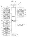
FIG. 1 is a block diagram illustrating a mobile terminal according to an embodiment of the present invention; -
FIG. 2 is a flow chart for explaining an embodiment of the control method applied to the mobile terminal illustrated inFIG. 1 ; -
FIGS. 3A ,3B ,4A ,4B ,5A , and5B are conceptual views illustrating operation examples according to the control method illustrated inFIG. 2 ; -
FIG. 6 is a conceptual view illustrating a case where an object fix mode associated with the control method illustrated inFIG. 2 is carried out in an exemplary manner; -
FIGS. 7 through 12 are conceptual views illustrating the embodiments of an additional object control method associated with the control method illustrated inFIG. 2 ; -
FIGS. 13A through 13C are conceptual views illustrating a visual effect associated with an embodiment of the control method applied to a mobile terminal according to the present invention; -
FIGS. 14A and 14B are conceptual views illustrating an object detection range associated with an embodiment of the control method applied to a mobile terminal according to the present invention; -
FIG. 15 is a flow chart for explaining another embodiment of the control method applied to the mobile terminal illustrated inFIG. 1 ; -
FIGS. 16A and16B are conceptual views illustrating operation examples according to the control method illustrated inFIG. 15 ; -
FIG. 17 is a flow chart for explaining still another embodiment of the control method applied to the mobile terminal illustrated inFIG. 1 ; and -
FIG. 18 is a conceptual view illustrating an operation example according to the control method illustrated inFIG. 17 . - Hereinafter, an embodiment of the present invention will be described with reference to the accompanying drawings to describe in detail to the extent that the technical spirit of the present invention can be easily implemented by those skilled in the art. However, the present invention may be implemented in various forms, and not be limited to the embodiment described herein. Furthermore, the elements having no relevance to the description will be omitted to clearly describe the present invention in the drawings, and the same or similar elements are designated with the same reference numerals throughout the entire specification.
- A terminal disclosed herein may include a portable phone, a smart phone, a laptop computer, a digital broadcast terminal, a personal digital assistant (PDA), a portable multimedia player (PMP), a navigator, and the like. However, it would be easily understood by those skilled in the art that a configuration disclosed herein may be applicable to stationary terminals such as a digital TV, a desktop computer, and the like, excluding constituent elements particularly configured only for a mobile terminal.
-
FIG. 1 is a block diagram illustrating amobile terminal 100 associated with an embodiment of the present invention. Referring toFIG. 1 , themobile terminal 100 may include awireless communication unit 110, an audio/video (A/V)input unit 120, auser input unit 130, asensing unit 140, anoutput unit 150, amemory 160, aninterface unit 170, acontroller 180, apower supply unit 190, and the like. However, the constituent elements as illustrated inFIG. 1 are not necessarily required, and the mobile terminal may be implemented with greater or less number of elements than those illustrated elements. - Hereinafter, the constituent elements 110-190 of the
mobile terminal 100 will be described in sequence. - The
wireless communication unit 110 typically includes one or more elements allowing radio communication between themobile terminal 100 and a wireless communication system, or allowing radio communication between radio communication themobile terminal 100 and a network in which themobile terminal 100 is located. For example, thewireless communication unit 110 may include abroadcast receiving module 111, amobile communication module 112, awireless Internet module 113, a short-range communication module 114, alocation information module 115, and the like. - The
broadcast receiving module 111 receives broadcast signals and/or broadcast associated information from an external broadcast management server through a broadcast channel. Here, the broadcast associated information may mean information regarding a broadcast channel, a broadcast program, a broadcast service provider, and the like. The broadcast associated information may also be provided through a mobile communication network, and in this case, the broadcast associated information may be received by themobile communication module 112. The broadcast signal and/or broadcast-associated information received through thebroadcast receiving module 111 may be stored in thememory 160. - The
mobile communication module 112 transmits and/or receives a radio signal to and/or from at least one of a base station, an external terminal and a server over a mobile communication network. Here, the radio signal may include a voice call signal, a video call signal and/or various types of data according to text and/or multimedia message transmission and/or reception. - The
wireless Internet module 113, as a module for supporting wireless Internet access, may be built-in or externally installed to themobile terminal 100. Here, it may be used a wireless Internet technique including a WLAN (Wireless LAN), Wi-Fi, Wibro (Wireless Broadband), Wimax (World Interoperability for Microwave Access), HSDPA (High Speed Downlink Packet Access), and the like. - The short-
range communication module 114 is a module for supporting a short-range communication. Here, it may be used a short-range communication technology including Bluetooth, Radio Frequency IDentification (RFID), Infrared Data Association (lrDA), Ultra WideBand (UWB), ZigBee, and the like. - The
location information module 115 is a module for checking or acquiring a location of the mobile terminal, and there is a GPS module as a representative example. - Referring to
FIG. 1 , the A/V(audio/video)input unit 120 receives an audio or video signal, and the A/V (audio/video)input unit 120 may include acamera 121, amicrophone 122, and the like. Thecamera 121 processes an image frame such as a still or moving image obtained by an image sensor in a video phone call or image capturing mode. The processed image frame may be displayed on adisplay unit 151. The image frames processed by thecamera 121 may be stored in thememory 160 or transmitted to an external device through thewireless communication unit 110. Two ormore cameras 121 may be provided according to the use environment of the mobile terminal. - The
microphone 122 receives an external audio signal through a microphone in a phone call mode, a recording mode, a voice recognition mode, and the like, and processes the audio signal into electrical voice data. The processed voice data processed by themicrophone 122 may be converted and outputted into a format that is transmittable to a mobile communication base station through themobile communication module 112 in the phone call mode. Themicrophone 122 may implement various types of noise canceling algorithms to cancel noise generated in a procedure of receiving the external audio signal. - The
user input unit 130 may generate input data to control an operation of the terminal. Theuser input unit 130 may be configured by including a key pad, a dome switch, a touch pad (pressure/capacitance), a jog wheel, a jog switch, and the like. - The
sensing unit 140 detects a current status of themobile terminal 100 such as an opened or closed status of themobile terminal 100, a location of themobile terminal 100, an orientation of themobile terminal 100, and the like, and generates a sensing signal for controlling the operation of themobile terminal 100. For example, when themobile terminal 100 is a slide phone type, it may sense an opened or closed status of the slide phone. Furthermore, thesensing unit 140 takes charge of a sensing function associated with whether or not power is supplied from thepower supply unit 190, or whether or not an external device is coupled to theinterface unit 170. - The
sensing unit 140 may include aproximity sensor 141, a solidtouch sensing unit 142, aultrasound sensing unit 143, and acamera sensing unit 144. Thesensing unit 140 may be configured with a three-dimensional sensor for detecting the location of a subject (hereinafter, referred to as a "detection target") existing and moving in a three-dimensional detection region. - Furthermore, the
sensing unit 140 may include a touch sensor (not shown) for sensing a touch operation to thedisplay unit 151. The touch sensor may be implemented as a touch film, a touch sheet, a touch pad, and the like. The touch sensor may be configured to convert changes of a pressure applied to a specific part of thedisplay unit 151, or a capacitance occurring from a specific part of thedisplay unit 151, into electric input signals. Also, the touch sensor may be configured to sense not only a touched position and a touched area, but also a touch pressure. - When the
display unit 151 and a touch sensitive sensor (referred to as a touch sensor) have a layered structure therebetween, thedisplay unit 151 may be used as an input device rather than an output device. Thedisplay unit 151 may be referred to as a "touch screen". - When there is a touch input through the touch screen, the corresponding signals are sent to a touch controller (not shown). The touch controller processes the received signals, and then transmits data corresponding to the processed signals to the
controller 180. Accordingly, thecontroller 180 may sense which region of thedisplay unit 151 has been touched. - When the touch screen is implemented with a capacitance type, it may be configured such that the proximity of a detection target is sensed by changes of an electromagnetic field. In this case, the touch screen may be categorized into a
proximity sensor 141. - The
proximity sensor 141 refers to a sensor to detect the presence or absence of a detection target using an electromagnetic field or infrared rays without a mechanical contact. Theproximity sensor 141 may include a transmissive type photoelectric sensor, a direct reflective type photoelectric sensor, a mirror reflective type photoelectric sensor, a high-frequency oscillation proximity sensor, a capacitance type proximity sensor, a magnetic type proximity sensor, an infrared rays proximity sensor, and so on. - The
proximity sensor 141 may be disposed at an inner region of themobile terminal 100 covered by the touch screen, or adjacent to the touch screen. - The
proximity sensor 141 measures a distance between the detection target (for example, the user's finger or stylus pen) and the detection surface to which a touch is applied using an electromagnetic field or infrared rays without a mechanical contact. Theproximity sensor 141 may recognize which portion of a stereoscopic image has been touched by using the measured distance. - On the other hand, the
proximity sensor 141 may be configured to sense a touch on a three-dimensional space using a proximity level of the detection target. - The solid
touch sensing unit 142 may be configured to sense the strength, frequency or duration time of a touch applied to the touch screen. For example, solidtouch sensing unit 142 senses a user applied touch pressure, and if the applied pressure is strong, then the solidtouch sensing unit 142 recognizes it as a touch for an object located farther from the touch screen. - The
ultrasound sensing unit 143 may be configured to sense the location of the detection target using ultrasound. For example, theultrasound sensing unit 143 may be configured with an optical sensor and a plurality of ultrasound sensors. - The optical sensor may be configured to sense light. For example, the optical sensor may be an infrared data association (IRDA) for sensing infrared rays.
- The ultrasound sensor may be configured to sense ultrasound waves. A plurality of ultrasound sensors are arranged to be separated from one another, and through this configuration, the plurality of ultrasound sensors may have a time difference in sensing ultrasound waves generated from the same or adjoining point.
- Ultrasound waves and light are generated from a wave generating source. The wave generating source may be provided in the detection target, for example, a stylus pen. Since light is far faster than ultrasound waves, the time for light to reach the optical sensor is far faster than the time for ultrasound waves to reach the optical sensor. Accordingly, the location of the wave generating source may be calculated by using a time difference between the light and ultrasound waves to reach the optical sensor.
- The
camera sensing unit 144 may include at least one of a camera, a laser sensor, and a photo sensor. For example, the camera and laser sensor may be combined to each other to sense a touch of the detection target to a three-dimensional stereoscopic image. Distance information sensed by the laser sensor is added to a two-dimensional image captured by the camera to acquire three-dimensional information. - For another example, a photo sensor may be deposited on the display element. The photo sensor may be configured to scan the motion of the detection target in proximity to the touch screen. More specifically, the photo sensor is integrated with photo diodes (PDs) and transistors in the rows and columns thereof, and a content placed on the photo sensor may be scanned by using an electrical signal that is changed according to the amount of light applied to the photo diode. In other words, the location coordinate of the detection target according to the changed amount of light may be detected through the photo sensor.
- The
output unit 150 is configured to provide an output associated with visual sense, auditory sense, tactile sense, and the like, and theoutput unit 150 may include thedisplay unit 151, anaudio output module 153, analarm unit 153, ahaptic module 153, and the like. - The
display unit 151 may display (output) information processed in themobile terminal 100. For example, when themobile terminal 100 is in a phone call mode, thedisplay unit 151 may display a User Interface (UI) or a Graphic User Interface (GUI) associated with a call. When themobile terminal 100 is in a video call mode or image capturing mode, thedisplay unit 151 may display a captured image and/or received image, a UI or GUI. - The
display unit 151 may include at least one of a Liquid Crystal Display (LCD), a Thin Film Transistor-LCD (TFT-LCD), an Organic Light Emitting Diode (OLED) display, a flexible display, a three-dimensional (3D) display, and an e-ink display. - At least one display (or display element) included in the
display unit 151 may be configured with a transparent or optical transparent type to allow viewing of the exterior through the display unit. It may be referred to as a transparent display. An example of the typical transparent displays may include a transparent LCD (TOLED), and the like. Under this configuration, a user can view an object positioned at a rear side of a terminal body through a region occupied by thedisplay unit 151 of the terminal body. - The
display unit 151 may be implemented in two or more in number according to a configured aspect of themobile terminal 100. For instance, a plurality of thedisplay units 151 may be arranged on one surface to be spaced apart from or integrated with each other, or may be arranged on different surfaces. - The
display unit 151 may be configured with asolid display unit 152 for displaying a stereoscopic image. Here, the stereoscopic image indicates a three-dimensional stereoscopic image, and the three-dimensional stereoscopic image is an image for allowing the user to feel the gradual depth and reality of an object located on the monitor or screen as in the real space. - The three-dimensional stereoscopic image may be implemented by using binocular disparity. Here, binocular disparity denotes a disparity made by the location of two eyes separated by about 65 mm, allowing the user to feel the depth and reality of a stereoscopic image when two eyes see different two-dimensional images and then the images are transferred through the retina and merged in the brain as a single image.
- A stereoscopic method (glasses method), an auto-stereoscopic method (no-glasses method), a projection method (holographic method), and the like may be applicable to the
solid display unit 152. The stereoscopic method primarily used in a home television receiver and the like may include a Wheatstone stereoscopic method and the like. - The examples of the auto-stereoscopic method may include a parallel barrier method, a lenticular method, an integral imaging method, and the like. The projection method may include a reflective holographic method, a transmissive holographic method, and the like.
- In general, a three-dimensional stereoscopic image may include a left image (image for the left eye) and a right image (image for the right eye). The method of implementing a three-dimensional stereoscopic image can be divided into a top-down method in which a left image and a right image are disposed at the top and bottom within a frame, a left-to-right (L-to-R) or side by side method in which a left image and a right image are disposed at the left and right within a frame, a checker board method in which the pieces of a left image and a right image are disposed in a tile format, an interlaced method in which a left and a right image are alternately disposed for each column and row unit, and a time sequential or frame by frame method in which a left image and a right image are alternately displayed for each time frame, according to the method of combining a left image and a right image into a three-dimensional stereoscopic image.
- As an example of the three-dimensional stereoscopic image, for three-dimensional thumbnail images, a left image thumbnail and a right image thumbnail may be generated from the left and the right image of the original image frame, and then combined with each other to generate a three-dimensional stereoscopic image. Typically, thumbnail denotes a reduced image or reduced still video. The left and right thumbnail image generated in this manner are displayed with a left and right distance difference on the screen in a depth corresponding to the disparity of the left and right image, thereby implementing a solid space feeling.
- When the
solid display unit 152 and a touch sensor are configured with an interlayer structure or thesolid display unit 152 and a 3D sensor for detecting a touch operation are combined with each other, thesolid display unit 152 may be used as a three-dimensional input device. Thesolid display unit 152 may be referred to as a "solid touch screen". - The
audio output module 153 may output audio data received from thewireless communication unit 110 or stored in thememory 160, in a call-receiving mode, a call-placing mode, a recording mode, a voice recognition mode, a broadcast reception mode, and so on. Theaudio output module 153 may output audio signals relating to the functions performed in the mobile terminal 100 (e.g., sound alarming a call received or a message received, and so on). Theaudio output module 153 may include a receiver, a speaker, a buzzer, and so on. - The
alarm 154 outputs signals notifying occurrence of events from themobile terminal 100. The events occurring from themobile terminal 100 may include call received, message received, key signal input, touch input, and so on. - The
alarm 154 may output not only video or audio signals, but also other types of signals such as signals notifying occurrence of events in a vibration manner. Since the video or audio signals can be output through thedisplay unit 151 or theaudio output unit 153, thedisplay unit 151 and theaudio output module 153 may be categorized into part of thealarm 154. - The
haptic module 155 generates various tactile effects which a user can feel. A representative example of the tactile effects generated by thehaptic module 154 includes vibration. Vibration generated by thehaptic module 154 may have a controllable intensity, a controllable pattern, and so on. For instance, different vibration may be output in a synthesized manner or in a sequential manner. - The
haptic module 155 may generate various tactile effects, including not only vibration, but also arrangement of pins vertically moving with respect to a skin being touched, air injection force or air suction force through an injection hole or a suction hole, touch by a skin surface, presence or absence of contact with an electrode, effects by stimulus such as an electrostatic force, reproduction of cold or hot feeling using a heat absorbing device or a heat emitting device, and the like. - The
haptic module 155 may be configured to transmit tactile effects through a user's direct contact, or a user's muscular sense using a finger or a hand. Thehaptic module 155 may be implemented in two or more in number according to the configuration of themobile terminal 100. - The
memory 160 may store a program for processing and controlling thecontroller 180. Alternatively, thememory 160 may temporarily store input/output data (e.g., phonebook, messages, still images, videos, and the like). Also, thememory 160 may store data related to various patterns of vibrations and sounds outputted upon the touch input on the touch screen. - The
memory 160 may be implemented using any type of suitable storage medium including a flash memory type, a hard disk type, a multimedia card micro type, a memory card type (e.g., SD or DX memory), Random Access Memory (RAM), Static Random Access Memory (SRAM), Read-Only Memory (ROM), Electrically Erasable Programmable Read-only Memory (EEPROM), Programmable Read-only Memory (PROM), magnetic memory, magnetic disk, optical disk, and the like. Also, themobile terminal 100 may operate in association with a web storage which performs the storage function of thememory 160 on the Internet. - The
interface unit 170 may generally be implemented to interface the portable terminal with external devices connected to themobile terminal 100. Theinterface unit 170 may allow a data reception from an external device, a power delivery to each component in themobile terminal 100, or a data transmission from themobile terminal 100 to an external device. Theinterface unit 170 may include, for example, wired/wireless headset ports, external charger ports, wired/wireless data ports, memory card ports, ports for coupling devices having an identification module, audio Input/Output (I/O) ports, video I/O ports, earphone ports, and the like. - The identification module may be configured as a chip for storing various information required to authenticate an authority to use the
mobile terminal 100, which may include a User Identity Module (UIM), a Subscriber Identity Module (SIM), and the like. Also, the device having the identification module (hereinafter, referred to as "identification device") may be implemented in a type of smart card. Hence, the identification device can be coupled to themobile terminal 100 via a port. - Also, the
interface unit 170 may serve as a path for power to be supplied from an external cradle to themobile terminal 100 when themobile terminal 100 is connected to the external cradle or as a path for transferring various command signals inputted from the cradle by a user to themobile terminal 100. Such various command signals or power inputted from the cradle may operate as signals for recognizing that themobile terminal 100 has accurately been mounted to the cradle. - The
controller 180 typically controls the overall operations of themobile terminal 100. For example, thecontroller 180 performs the control and processing associated with telephony calls, data communications, video calls, and the like. Thecontroller 180 may include amultimedia module 181 which provides multimedia playback. Themultimedia module 181 may be configured as part of thecontroller 180 or as a separate component. - The
controller 180 can perform a pattern recognition processing so as to recognize writing or drawing input carried out on the touch screen as text or image. - The
power supply unit 190 receives external and internal power to provide power required for various components under the control of thecontroller 180. - Various embodiments described herein may be implemented in a computer or similar device readable medium using software, hardware, or any combination thereof.
- For hardware implementation, it may be implemented by using at least one of application specific integrated circuits (ASICs), digital signal processors (DSPs), digital signal processing devices (DSPDs), programmable logic devices (PLDs), field programmable gate arrays (FPGAs), processors, controllers, microcontrollers, microprocessors, and electrical units designed to perform the functions described herein. In some cases, such embodiments may be implemented in the
controller 180 itself. - For software implementation, the embodiments such as procedures or functions may be implemented together with separate software modules that allow performing of at least one function or operation. Software codes can be implemented by a software application written in any suitable programming language. The software codes may be stored in the
memory 160 and executed by thecontroller 180. - Hereinafter, the processing method of a user input to the
mobile terminal 100 will be described. - The
user input unit 130 is manipulated to receive a command for controlling the operation of theportable terminal 100, and may include a plurality of manipulation units. The manipulation units may be commonly designated as a manipulating portion, and any method may be employed if it is a tactile manner allowing the user to perform manipulation with a tactile feeling. - Various kinds of visual information may be displayed on the
display unit 151. The visual information may be displayed in a form of characters, numerals, symbols, graphics, or icons, or may be implemented in three-dimensional stereoscopic images. For an input of the visual information, at least one of the characters, numerals, symbols, graphics, or icons may be displayed with a predetermined arrangement so as to be implemented in a form of keypad. Such a keypad may be referred to as a so-called "soft key." - The
display unit 151 may operate on an entire region or operate by dividing into a plurality of regions. In case of the latter, the plurality of regions may be configured to operate in an associative way. For example, an output window and an input window may be displayed on the upper portion and lower portion of the display unit, respectively. The output window and the input window may be regions allocated to output or input information, respectively. A soft key on which numerals for inputting phone numbers or the like are displayed is outputted on the input window. When the soft key is touched, numerals corresponding to the touched soft key are displayed on the output window. When the manipulating unit is manipulated, a call connection for the phone number displayed on the output window is attempted or a text displayed on the output window may be input to an application. - The
display unit 151 or the touch pad may be configured to sense a touch scroll. The user may move an object displayed on thedisplay unit 151, for example, a cursor or pointer placed on an icon, by scrolling thedisplay unit 151 or the touch pad. Moreover, when a finger is moved on thedisplay unit 151 or the touch pad, a path being moved by the finger may be visually displayed on thedisplay unit 151. It may be useful to edit an image displayed on thedisplay unit 151. - In order to cope with a case where the
display unit 151 and the touch pad are touched together within a predetermined period of time, one function of themobile terminal 100 may be executed. As a case of being touched together, there is a case when the user clamps a terminal body of themobile terminal 100 using the thumb and forefinger. For one of the functions executed in themobile terminal 100, there may be an activation or de-activation for thedisplay unit 151 or the touch pad. - Hereinafter, a mechanism for controlling objects using a distance change between the objects displayed on a three-dimensional stereoscopic image in the
mobile terminal 100 will be described. -
FIG. 2 is a flow chart for explaining an embodiment of the control method applied to themobile terminal 100 illustrated inFIG. 1 . Referring toFIG. 2 , in the step S110, a three-dimensional stereoscopic image including a plurality of objects is displayed. The solid display unit 152 (refer toFIG. 1 ) may output a three-dimensional stereoscopic image implemented by the direct image method. The three-dimensional stereoscopic image may be implemented in the form of being protruded or sunken out of or into themobile terminal 100 with respect to a window of themobile terminal 100, for example, a surface of thesolid display unit 152. - In the step S120, the location of the detection target is sensed in a detection region corresponding to the three-dimensional stereoscopic image. The sensing unit 140 (refer to
FIG. 1 ) may sense a two-dimensional location of the detection target, for example, a location on a surface in parallel to the window of themobile terminal 100. Furthermore, thesensing unit 140 may sense a three-dimensional location of the detection target, for example, a location including a vertical distance with respect to the window of themobile terminal 100. - In the step S130, at least one of a plurality of objects included in the three-dimensional stereoscopic image may be selected based on the location of the detection target. The
controller 180 may select at least one of the plurality of objects using the location information of the detection target provided from thesensing unit 140. At this time, the location of an object that has been selected in the three-dimensional stereoscopic image may correspond to the location of the detection target in a detection region. - In the step S140, the selected object is moved along the movement of the detection target. For example, when the detection target moves in one direction, the selected object may be also moved in the same direction as the moving direction of the detection target.
- In the step S150, due to the movement of the selected object, it is determined to which direction a distance between the selected object and the other object is changed. As a result of the determination, when a distance between the selected object and the other object is changed to a vertical direction to the window of the mobile terminal 100 (hereinafter, referred to as a "vertical direction"), it advances to the step S160. On the contrary, when a distance between the selected object and the other object is changed to a horizontal direction to the window of the mobile terminal 100 (hereinafter, referred to as a "horizontal direction"), it advances to the step S190.
- In the step S160, it is determined whether a distance between the selected object and the other object is increased or decreased. As a result of the determination, when a distance between the selected object and the other object is increased, it advances to the step S170. In the step S170, another object is generated between the selected object and the other object. On the contrary, when a distance between the selected object and the other object is decreased, it advances to the step S180. In the step S180, at least one of objects displayed between the selected object and the other object is deleted.
- In the step S190, the location of objects displayed between the selected object and the other object is changed to a horizontal direction. For example, an interval of objects displayed between the selected object and the other object may be evenly controlled in a horizontal direction.
- As described above, according to an embodiment of the control method applied to the
mobile terminal 100 of the present invention, an object control operation may be carried out to move an object selected along the movement of the detection target in a three-dimensional space, and generate or delete at least one object according to a distance change between objects due to the movement of the selected object. Otherwise, an object control operation may be carried out to change the location (interval) of objects. - As a result, the objects of the
mobile terminal 100 may be effectively controlled by using a space being changed between objects without entering any other additional command except a command associated with the movement of the selected object. -
FIGS. 3A ,3B ,4A ,4B ,5A , and5B are conceptual views illustrating operation examples according to the control method illustrated inFIG. 2 . - In operation examples which will be described below, the
solid display unit 252 outputs a three-dimensional stereoscopic image implemented in the form of being protruded out of themobile terminal 200 with respect to a surface thereof. The sensing unit (not shown) senses the location of thedetection target 248 in adetection region 246 corresponding to the three-dimensional stereoscopic image. The controller (not shown) controls an object displayed on the three-dimensional stereoscopic image based on the location of thedetection target 248. -
FIGS. 3A and3B illustrate a case where an object 202 (hereinafter, referred to as a "first object") of the plurality ofobjects detection target 248. - Referring to
FIG. 3A , when a distance between thefirst object 202 and the unselected object 204 (hereinafter, referred to as a "second object") is increased in a vertical direction due to the movement of thefirst object 202, at least oneobject second object - At this time, various kinds of objects may be generated between the first and the
second object mobile terminal 200. For example, a vacant region (a region where nothing is displayed in a three-dimensional stereoscopic image), a memo pad or a vacant page in a web browser window, a clipboard, a virtual keyboard, an icon, a multimedia content, a control menu, a phone directory, a chat window, a widget, an e-book document, a spread sheet, and the like may be generated between the first and thesecond object - The number of objects displayed between the first and the
second object second object second object - The
objects second object objects objects - Referring to
FIG. 3B , when a distance between thefirst object 202 and thesecond object 204 is decreased in a vertical direction due to the movement of thefirst object 202, at least one ofobjects second object - At this time, the
objects second object object 208 may be deleted earlier than the previously generatedobject 206. -
FIGS. 4A and4B illustrate a case where thefirst object 202 is moved in a horizontal direction along the movement of thedetection target 248. For example,FIGS. 4A and4B illustrate a case where thefirst object 202 is moved in a different direction on a surface in parallel to thesolid display unit 252. - Referring to
FIGS. 4A and4B , thefirst object 202 is moved in a horizontal direction while maintaining a vertical direction to thesolid display unit 252. Then, the location ofobjects second object first object 202. For example, the location ofobjects second object objects -
Objects second object second object - In
FIGS. 5A and5B , another selected object 203 (hereinafter, referred to as a "third object) is further illustrated in addition to the first and thesecond object FIGS. 5A and5B illustrate a case where the first and thethird object detection target 248. In other words,FIGS. 5A and5B illustrate an embodiment of the control method using a multi-touch. - Referring to
FIG. 5A , the first and thethird object detection target 248. Then, when a distance between either one of the first and thethird object second object 204 is increased in a vertical direction due to the movement of the first and thethird object object 206 is generated between either one of the first and thethird object second object 204. For example, at least oneobject 206 may be generated between the first and thesecond object - Referring to
FIG. 5B , the first and thethird object detection target 248. Then, when a distance between the first and thethird object third object object 206 is generated between the first and thethird object -
FIG. 6 is a conceptual view illustrating a case where an object fix mode associated with the control method illustrated inFIG. 2 is carried out in an exemplary manner. Here, the object fix mode denotes a mode in which an object attribute is changed to fix the location of the selected object even when the detection target is moved. - Referring to
FIG. 6 , thefirst object 302 is fixed in response to a fix command entered by thedetection target 348. More specifically, the fix command is entered when thedetection target 348 drags thefirst object 302 out of thedetection region 346, and thefirst object 302 is fixed in response to the fix command. At this time, thefirst object 302 is moved along the movement of thefirst object 302 until receiving a fix command. - Though not shown in the drawing, a fix command may be entered by using a select key. Otherwise, the fix command may be entered based on at least one of a touch frequency and time of the
detection target 348 to thefirst object 302. - When an object fix mode is carried out, an indication indicating that the
first object 302 is fixed may be displayed on thefirst object 302. - According to an embodiment of the present invention, subsequent to performing an object fix mode, an additional operation for the
objects second object FIG. 2 to enhance the user's convenience will be described. -
FIGS. 7 through 12 are conceptual views illustrating the embodiments of an additional object control method associated with the control method illustrated inFIG. 2 . In the embodiments described with reference toFIGS. 7 through 11 , thesolid display unit 452 of themobile terminal 400 may output a three-dimensional stereoscopic image including a first through afourth object fourth object second object second object third object 406 described herein is different from thethird object 203 inFIGS. 5A and5B . - Referring to
FIG. 7 , thefourth object 408 is selected based on the location of thedetection target 448 in adetection region 446. When thefourth object 408 is selected, acontrol menu 401 associated with thefourth object 408 is displayed on a three-dimensional stereoscopic image. - The
control menu 401 may include a list for candidate objects such as a widget, a memo pad, an MP3 player, and the like. Here, the names of candidate objects displayed on a list of thecontrol menu 401 may be scrolled. - One object 405 (hereinafter, referred to as a "fifth object") of the candidate objects, for example, an MP3 player, may be selected according to the selection information entered by using the
control menu 401. Then, thefifth object 405 corresponding to the selection information entered by using thecontrol menu 401 may be added to thefourth object 408. - Referring to
FIG. 8 , thefourth object 408 is deleted in response to a delete command entered by thedetection target 448. More specifically, the delete command is entered when thedetection target 448 drags thefourth object 408 out of thedetection region 446, and thefourth object 408 is deleted in response to the delete command. - When the
fourth object 408 is deleted, the location at which thefourth object 408 is deleted may remain as a vacant region, or an additional control operation may be carried out. For example, when thefourth object 408 is deleted, the location of at least one of the remaining first throughthird objects third object 406 displayed between first and thesecond object third objects - For another example, when the
fourth object 408 is deleted, asixth object 409 substituting thefourth object 408 may be generated in a vacant region between the first and thesecond object sixth object 409 may be an object associated with the adjoining object. For example, thesixth object 409 may be an address book associated with e-mails. The vacant region between the first and thesecond object fourth object 408 has been located prior to deletion. - Referring to
FIG. 9 , thefourth object 408 is moved between the first and thesecond object detection target 448. Then, when thefourth object 408 is moved, the location of at least one of objects displayed between the first and thesecond object fourth object 408 is moved to a place at which thethird object 406 is located, the location of the third and thefourth object - Referring to
FIG. 10 , thefourth object 408 may include a clipboard. The clipboard may store various objects (Obj1-Obj3) such as a text, an image, and the like. An editing operation such as copy, cut, paste, or the like may be carried out by using the clipboard. For example, any one object (Obj2) stored within a clipboard is copied in response to a copy command entered by thedetection target 448, and the copied object (obj2) may be pasted to thethird object 406 in response to a paste command entered by thedetection target 448. - Referring to
FIG. 11 , thefourth object 408 may include a virtual keyboard 408'. When thefourth object 408 includes a virtual keyboard 408', data entered by using the virtual keyboard 408' may be displayed and stored in thefourth object 408. - More specifically, when a touch of the
detection target 448 to thefourth object 408 is sensed, the virtual keyboard 408' is enlarged and popped up, and data may be entered by using the virtual keyboard 408'. At this time, thefourth object 408 may be displayed to be inclined toward thesolid display unit 452. - Referring to
FIG. 12 , the third and thefourth object second object - More specifically, when the
detection target 448 drags the third and thefourth object detection region 446, and as a result, the third and thefourth object fourth object - For example, when the
fourth object 408 is moved to the grouped region 446' by a drag of thedetection target 448, and then thethird object 406 is moved to the grouped region 446' by a drag of thedetection target 448 and as a result the third and thefourth object fourth object - As described above, the user's convenience can be enhanced in controlling objects displayed in a three-dimensional stereoscopic image by supporting an additional control such as add, delete, group, edit, input operation and the like.
-
FIGS. 13A through 13C are conceptual views illustrating a visual effect associated with an embodiment of the control method applied to a mobile terminal according to the present invention. - In an embodiment described with reference to
FIGS. 13A through 13C , asolid display unit 552 of themobile terminal 500 may output a three-dimensional stereoscopic image including a first and asecond object second object first object 502, thethird object 506 is generated between the first and thesecond object - As a visual effect of illustrating that the
third object 506 is an object generated by controlling thefirst object 502, part of thethird object 506 may be displayed to be folded as illustrated inFIG. 13A , and thethird object 506 may be displayed to be inclined toward thesolid display unit 552 as illustrated inFIG. 13B , and thethird object 506 may be displayed to be enlarged in a two-dimensional manner as illustrated inFIG. 13C . - Though not shown in the drawing, as a visual effect of illustrating that the
third object 506 is an object generated by controlling thefirst object 502, it may be possible to change the shape, format, transparency, background color, text color, and the like in various manner for thethird object 506, or also give an effect such as highlight, underline, edge highlight, and the like for thethird object 506. Furthermore, information such as page number, graph, gauge numerical value, and the like may be displayed on thethird object 506. -
FIGS. 14A and 14B are conceptual views illustrating an object detection range associated with an embodiment of the control method applied to a mobile terminal according to the present invention. - Referring to
FIGS. 14A and 14B , when the sensing unit of the mobile terminal senses a detection target, a detection region corresponding to any oneobject 602 displayed in a three-dimensional stereoscopic image may be determined according to a vertical distance for theobject 602. For example, the detection region may become wider as being drawn away from theobject 602, and become narrower as being drawn near to theobject 602. Accordingly, the detection region on a plane located away from theobject 602 by a first vertical distance (d1), is narrower than the detection region on a plane located away by a second vertical distance (d2). - On the other hand, the shape of the detection region according to a vertical distance with respect to the
object 602 may be a circle as illustrated inFIG. 14A , or a rectangle as illustrated inFIG. 14B . However, the shape of the detection region may not be limited to this and implemented in a various manner. -
FIG. 15 is a flow chart for explaining another embodiment of the control method applied to themobile terminal 100 illustrated inFIG. 1 . Hereinafter, redundant description that has been already made in the control method illustrated inFIG. 2 will be omitted. - Referring to
FIG. 15 , a three-dimensional stereoscopic image including a plurality of objects is displayed on the solid display unit 152 (refer toFIG. 1 ) in the step S210. - In the step S220, an object selected from the plurality of objects is moved in a vertical direction based on at least one of the strength, frequency, and time of a touch applied to the
solid display unit 152. For example, an object selected according to the frequency of the touch applied to thesolid display unit 152 may be drawn away from thesolid display unit 152. For another example, an object selected according to the time of the touch applied to thesolid display unit 152 may be drawn near to thesolid display unit 152. - In the step S230, it may be determined whether a distance between the selected object and the other object is increased or decreased. As a result of the determination, when a distance between the selected object and the other object is increased, it advances to the step S240. In the step S240, another object is generated between the selected object and the other object. On the contrary, when a distance between the selected object and the other object is decreased, and it advances to the step S250. In the step S250, at least one of objects displayed between the selected object and the other object is deleted.
- As described above, according to another embodiment of the control method applied to the
mobile terminal 100 of present invention, it may be possible to perform an object control operation for moving the selected object in a vertical direction, and then generating or deleting at least one object according to the movement of the selected object. -
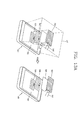
FIGS. 16A and16B are conceptual views illustrating operation examples according to the control method illustrated inFIG. 15 . - In operation examples described below, the
solid display unit 752 may output a three-dimensional stereoscopic image implemented in the form of being sunken into themobile terminal 700 with respect to a surface thereof. The sensing unit (not shown) senses a touch on thesolid display unit 752. The controller (not shown) controls objects displayed on the three-dimensional stereoscopic image based on the sensed touch. -
FIGS. 16A and16B illustrate a case where thefirst object 702 is moved in a vertical direction based on at least one of the strength, frequency, and time of a touch applied to thesolid display unit 752. For example, as the frequency of the touch applied to thesolid display unit 752 is increased, thefirst object 702 may be drawn away from thesolid display unit 752. For another example, as the time of the touch applied to thesolid display unit 752 is increased, thefirst object 702 may be drawn near to thesolid display unit 752. - Referring to
FIG. 16A , when a distance between the first and thesecond object first object 702, at least oneobject second object - Referring to
FIG. 16B , when a distance between the first and thesecond object first object 702, at least one of theobjects second object - At this time, the
objects second object object 708 may be deleted earlier than the previously generatedobject 706. -
FIG. 17 is a flow chart for explaining still another embodiment of the control method applied to themobile terminal 100 illustrated inFIG. 1 . Hereinafter, redundant description that has been already made in the control method illustrated inFIG. 2 will be omitted. - Referring to
FIG. 17 , in the step S130, a three-dimensional stereoscopic image including a plurality of objects is displayed on the solid display unit 152 (refer toFIG. 1 ). - In the step S320, an object selected among the plurality of objects is moved in a horizontal direction based on a drag on the
solid display unit 152. For example, the selected object may be drawn away from or drawn near to thesolid display unit 152 in the same direction as a drag direction on thesolid display unit 152. - In the step S330, when a distance between the selected object and the other object is changed to a horizontal direction due to the movement of the selected object, the location of objects displayed between the selected object and the other object is changed to a horizontal direction. For example, the interval of objects displayed between the selected object and the other object may be evenly controlled in a horizontal direction.
- As described above, according to still another embodiment of the control method applied to the
mobile terminal 100 of present invention, it may be possible to perform an object control operation for moving the selected object in a horizontal direction using a drag on thesolid display unit 152, and then changing the location (interval) of objects according to the movement of the selected object. -
FIG. 18 is a conceptual view illustrating an operation example according to the control method illustrated inFIG. 17 . - According to an operation example described herein, the
solid display unit 852 may output a three-dimensional stereoscopic image implemented in the form of being sunken into themobile terminal 800 with respect to a surface thereof. The sensing unit (not shown) senses a drag on thesolid display unit 852. The controller (not shown) controls objects displayed on the three-dimensional stereoscopic image based on the sensed drag. - Referring to
FIG. 18 , thefirst object 802 is moved in the same direction as the drag direction on thesolid display unit 852 while maintaining a vertical distance with respect to thesolid display unit 852. Then, the location ofobjects second object first object 802. For example, the location ofobjects second object objects - The
objects second object second object - As described above, according to a mobile terminal and control method thereof according to an embodiment of the present invention, it may be possible to perform an object control operation for moving a selected object according to the movement of the detection target in a three-dimensional space, and then generating or deleting at least one object, or changing the location (interval) of objects according to a distance change between objects due to the movement of the selected object. As a result, objects may be effectively controlled by using a space changed between the objects without entering an additional command except a command associated with the movement of the selected object.
- Furthermore, the user's convenience can be enhanced in controlling objects displayed in a three-dimensional stereoscopic image by supporting an additional control such as add, delete, group, edit, input operation and the like for objects.
- It should be understood by those skilled in the art that various modifications and changes can be made in the structure of the present invention without departing from the scope and technical spirit of the invention. Taking the foregoing description into consideration, if the modifications and variations are included within the scope of the following claims and equivalents thereof, then it should be understood that the present invention includes the modifications and changes thereof.
Claims (15)
- A method of controlling a mobile terminal, the method comprising:displaying a three-dimensional stereoscopic image including a plurality of objects;detecting the location of a detection target in a detection region corresponding to the three-dimensional stereoscopic image;selecting a first object based on the location of the detection target;moving the first object along the movement of the detection target in a state that the first object is selected; andgenerating at least one object between the first and the second object when a distance between the first and the second object is increased in one direction due to the movement of the first object.
- The method of claim 1, further comprising:deleting at least one of objects displayed between the first and the second object when a distance between the first and the second object is decreased in one direction due to the movement of the first object.
- The method of claim 2, wherein the one direction is a vertical direction with respect to a display unit for outputting the three-dimensional stereoscopic image.
- The method of claim 3, further comprising:changing the location of objects displayed between first and the second object to the other direction when a distance between the first and the second object is changed to the other direction perpendicular to the one direction.
- The method of claim 3, further comprising:selecting a third object based on the location of the detection target;moving the first and the third object along the movement of the detection target in a state that the first and the third object are selected; andgenerating at least one object between the first and the third object when a distance between the first and the third object is increased in one direction due to the movement of the first and the third object.
- The method of claim 1, further comprising:selecting a fourth object generated between the first and the second object based on the location of the detection target; andcontrolling the fourth object in a state that the fourth object is selected.
- The method of claim 6, wherein said controlling the fourth object comprises:displaying a control menu associated with the fourth object; andadding a fifth object corresponding to selection information entered by using the control menu to the fourth object.
- The method of claim 6, wherein said controlling the fourth object comprises:deleting the fourth object in response to a delete command entered by the detection target.
- The method of claim 6, wherein said controlling the fourth object comprises:moving the fourth object between the first and the second object along the movement of the detection target.
- The method of claim 6, wherein said controlling the fourth object comprises performing an editing operation using a clipboard when the fourth object comprises the clipboard.
- The method of claim 6, wherein said controlling the fourth object comprises displaying and storing data entered by using a virtual keyboard in the fourth object when the fourth object comprises the virtual keyboard.
- The method of claim 1, further comprising:grouping the third and the fourth object when the third and fourth object displayed between the first and the second object are located in a grouped region within the three-dimensional stereoscopic image.
- A mobile terminal, comprising:a terminal body;a display unit (151) formed on the terminal body, and configured to display a three-dimensional stereoscopic image including a first and a second object;a detection unit (140) mounted on the terminal body to detect the location of a detection target in a detection region corresponding to the three-dimensional stereoscopic image; anda controller (180) configured to select the first object based on the location of the detection target, move the first object along the movement of the detection target in a state that the first object is selected, and generate at least one object between the first and the second object when a distance between the first and the second object is increased in one direction due to the movement of the first object.
- The mobile terminal of claim 13, wherein the controller (180) deletes at least one of objects displayed between the first and the second object when a distance between the first and the second object is decreased in one direction due to the movement of the first object.
- The mobile terminal of claim 14, wherein the controller (1800 changes the location of objects displayed between first and the second object to the other direction when a distance between the first and the second object is changed to the other direction perpendicular to the one direction.
Applications Claiming Priority (1)
| Application Number | Priority Date | Filing Date | Title |
|---|---|---|---|
| KR1020110026589A KR101781908B1 (en) | 2011-03-24 | 2011-03-24 | Mobile terminal and control method thereof |
Publications (3)
| Publication Number | Publication Date |
|---|---|
| EP2503438A2 true EP2503438A2 (en) | 2012-09-26 |
| EP2503438A3 EP2503438A3 (en) | 2016-06-08 |
| EP2503438B1 EP2503438B1 (en) | 2018-08-22 |
Family
ID=44897588
Family Applications (1)
| Application Number | Title | Priority Date | Filing Date |
|---|---|---|---|
| EP11007902.7A Not-in-force EP2503438B1 (en) | 2011-03-24 | 2011-09-29 | Mobile terminal and control method thereof |
Country Status (4)
| Country | Link |
|---|---|
| US (1) | US8797317B2 (en) |
| EP (1) | EP2503438B1 (en) |
| KR (1) | KR101781908B1 (en) |
| CN (1) | CN102693069B (en) |
Cited By (2)
| Publication number | Priority date | Publication date | Assignee | Title |
|---|---|---|---|---|
| WO2016072676A1 (en) | 2014-11-05 | 2016-05-12 | Samsung Electronics Co., Ltd. | Method of displaying object on device, device for performing the same, and recording medium for performing the method |
| WO2020144016A1 (en) * | 2019-01-07 | 2020-07-16 | Continental Automotive Gmbh | Operating device for operating at least one appliance, and method for operating such an operating device |
Families Citing this family (12)
| Publication number | Priority date | Publication date | Assignee | Title |
|---|---|---|---|---|
| JP5785753B2 (en) * | 2011-03-25 | 2015-09-30 | 京セラ株式会社 | Electronic device, control method, and control program |
| US20140089859A1 (en) * | 2011-05-24 | 2014-03-27 | Mitsubishi Electric Corporation | Equipment control device, operation reception method, and program |
| US20120304090A1 (en) * | 2011-05-28 | 2012-11-29 | Microsoft Corporation | Insertion of picture content for use in a layout |
| EP2730998B1 (en) * | 2011-07-04 | 2018-05-02 | NEC Corporation | Image processing device, image processing method, and image processing program |
| US8943582B1 (en) * | 2012-07-18 | 2015-01-27 | Amazon Technologies, Inc. | Transferring information among devices using cameras |
| JP5751233B2 (en) * | 2012-10-02 | 2015-07-22 | 株式会社デンソー | Operation device |
| US9652115B2 (en) * | 2013-02-26 | 2017-05-16 | Google Inc. | Vertical floor expansion on an interactive digital map |
| JP6206099B2 (en) * | 2013-11-05 | 2017-10-04 | セイコーエプソン株式会社 | Image display system, method for controlling image display system, and head-mounted display device |
| KR102337216B1 (en) * | 2015-01-05 | 2021-12-08 | 삼성전자주식회사 | Image display apparatus and method for displaying image |
| CN107823877A (en) * | 2016-09-16 | 2018-03-23 | 天津思博科科技发展有限公司 | The fantasy sport game device realized using three-dimensional localization sensor |
| KR102316024B1 (en) * | 2017-03-02 | 2021-10-26 | 삼성전자주식회사 | Display apparatus and user interface displaying method thereof |
| US11497569B2 (en) * | 2017-08-01 | 2022-11-15 | Intuitive Surgical Operations, Inc. | Touchscreen user interface for interacting with a virtual model |
Family Cites Families (19)
| Publication number | Priority date | Publication date | Assignee | Title |
|---|---|---|---|---|
| US6727924B1 (en) * | 2000-10-17 | 2004-04-27 | Novint Technologies, Inc. | Human-computer interface including efficient three-dimensional controls |
| US7043701B2 (en) * | 2002-01-07 | 2006-05-09 | Xerox Corporation | Opacity desktop with depth perception |
| JP4325449B2 (en) | 2004-03-19 | 2009-09-02 | ソニー株式会社 | Display control device, display control method, and recording medium |
| JP4274997B2 (en) | 2004-05-06 | 2009-06-10 | アルパイン株式会社 | Operation input device and operation input method |
| KR100608589B1 (en) * | 2004-07-24 | 2006-08-03 | 삼성전자주식회사 | Three dimensional motion graphic user interface and method and apparutus for providing this user interface |
| CN101308442B (en) * | 2004-10-12 | 2012-04-04 | 日本电信电话株式会社 | 3d pointing method and 3d pointing device |
| US8334841B2 (en) * | 2006-03-13 | 2012-12-18 | Navisense | Virtual user interface method and system thereof |
| US8578282B2 (en) * | 2006-03-15 | 2013-11-05 | Navisense | Visual toolkit for a virtual user interface |
| WO2007121557A1 (en) * | 2006-04-21 | 2007-11-01 | Anand Agarawala | System for organizing and visualizing display objects |
| US8284165B2 (en) * | 2006-10-13 | 2012-10-09 | Sony Corporation | Information display apparatus with proximity detection performance and information display method using the same |
| US8726194B2 (en) * | 2007-07-27 | 2014-05-13 | Qualcomm Incorporated | Item selection using enhanced control |
| US9513765B2 (en) * | 2007-12-07 | 2016-12-06 | Sony Corporation | Three-dimensional sliding object arrangement method and system |
| US8576181B2 (en) * | 2008-05-20 | 2013-11-05 | Lg Electronics Inc. | Mobile terminal using proximity touch and wallpaper controlling method thereof |
| KR101481556B1 (en) * | 2008-09-10 | 2015-01-13 | 엘지전자 주식회사 | A mobile telecommunication terminal and a method of displying an object using the same |
| KR101586627B1 (en) * | 2008-10-06 | 2016-01-19 | 삼성전자주식회사 | A method for controlling of list with multi touch and apparatus thereof |
| KR20100041006A (en) * | 2008-10-13 | 2010-04-22 | 엘지전자 주식회사 | A user interface controlling method using three dimension multi-touch |
| JP5563250B2 (en) * | 2009-06-30 | 2014-07-30 | 株式会社ジャパンディスプレイ | Stereoscopic image display device |
| US20120005624A1 (en) * | 2010-07-02 | 2012-01-05 | Vesely Michael A | User Interface Elements for Use within a Three Dimensional Scene |
| CN101989179A (en) | 2010-11-09 | 2011-03-23 | 福州瑞芯微电子有限公司 | Implementation method for advancing three-dimensional user interface and mobile terminal |
-
2011
- 2011-03-24 KR KR1020110026589A patent/KR101781908B1/en active IP Right Grant
- 2011-07-08 US US13/178,780 patent/US8797317B2/en not_active Expired - Fee Related
- 2011-08-16 CN CN201110251163.3A patent/CN102693069B/en not_active Expired - Fee Related
- 2011-09-29 EP EP11007902.7A patent/EP2503438B1/en not_active Not-in-force
Non-Patent Citations (1)
| Title |
|---|
| None |
Cited By (5)
| Publication number | Priority date | Publication date | Assignee | Title |
|---|---|---|---|---|
| WO2016072676A1 (en) | 2014-11-05 | 2016-05-12 | Samsung Electronics Co., Ltd. | Method of displaying object on device, device for performing the same, and recording medium for performing the method |
| EP3201736A4 (en) * | 2014-11-05 | 2017-08-09 | Samsung Electronics Co., Ltd. | Method of displaying object on device, device for performing the same, and recording medium for performing the method |
| US10929007B2 (en) | 2014-11-05 | 2021-02-23 | Samsung Electronics Co., Ltd. | Method of displaying object on device, device for performing the same, and recording medium for performing the method |
| EP3809250A1 (en) * | 2014-11-05 | 2021-04-21 | Samsung Electronics Co., Ltd. | Method of displaying object on device, device for performing the same, and recording medium for performing the method |
| WO2020144016A1 (en) * | 2019-01-07 | 2020-07-16 | Continental Automotive Gmbh | Operating device for operating at least one appliance, and method for operating such an operating device |
Also Published As
| Publication number | Publication date |
|---|---|
| KR20120109090A (en) | 2012-10-08 |
| CN102693069A (en) | 2012-09-26 |
| EP2503438B1 (en) | 2018-08-22 |
| CN102693069B (en) | 2015-04-22 |
| US20120242652A1 (en) | 2012-09-27 |
| KR101781908B1 (en) | 2017-09-26 |
| US8797317B2 (en) | 2014-08-05 |
| EP2503438A3 (en) | 2016-06-08 |
Similar Documents
| Publication | Publication Date | Title |
|---|---|---|
| EP2503438B1 (en) | Mobile terminal and control method thereof | |
| US8780076B2 (en) | Mobile terminal and method for controlling the same | |
| US10901574B2 (en) | Mobile terminal and method for multi-tasking using an extended region to display related content | |
| US10210319B2 (en) | Mobile terminal and control method for the mobile terminal | |
| EP3540578A1 (en) | Mobile terminal and method for controlling the same | |
| US10203761B2 (en) | Glass type mobile terminal | |
| US9460689B2 (en) | Mobile terminal and method for controlling the same | |
| US10691327B2 (en) | Mobile terminal and control method for the mobile terminal | |
| US10044928B2 (en) | Mobile terminal and method for controlling the same | |
| US10101844B2 (en) | Mobile terminal and method of controlling the same based on type of touch object used to apply touch input | |
| US9826143B2 (en) | Mobile terminal and control method thereof | |
| EP2418859A2 (en) | Method for controlling depth of image and mobile terminal using the method | |
| EP2979365B1 (en) | Mobile terminal and method of controlling the same | |
| EP2608009A2 (en) | Mobile terminal and control method thereof | |
| US10613744B2 (en) | Mobile terminal and method for controlling the same | |
| EP2752758A2 (en) | Image display device and controlling method thereof | |
| US10095348B2 (en) | Mobile terminal and method for controlling the same | |
| EP2990926A1 (en) | Mobile terminal and control method thereof | |
| US10739877B2 (en) | Mobile terminal and method for controlling same | |
| US10338774B2 (en) | Mobile terminal and method for controlling the same | |
| US20180348927A1 (en) | Mobile terminal and method of controlling the same | |
| US8941648B2 (en) | Mobile terminal and control method thereof |
Legal Events
| Date | Code | Title | Description |
|---|---|---|---|
| PUAI | Public reference made under article 153(3) epc to a published international application that has entered the european phase |
Free format text: ORIGINAL CODE: 0009012 |
|
| 17P | Request for examination filed |
Effective date: 20110929 |
|
| AK | Designated contracting states |
Kind code of ref document: A2 Designated state(s): AL AT BE BG CH CY CZ DE DK EE ES FI FR GB GR HR HU IE IS IT LI LT LU LV MC MK MT NL NO PL PT RO RS SE SI SK SM TR |
|
| AX | Request for extension of the european patent |
Extension state: BA ME |
|
| PUAL | Search report despatched |
Free format text: ORIGINAL CODE: 0009013 |
|
| AK | Designated contracting states |
Kind code of ref document: A3 Designated state(s): AL AT BE BG CH CY CZ DE DK EE ES FI FR GB GR HR HU IE IS IT LI LT LU LV MC MK MT NL NO PL PT RO RS SE SI SK SM TR |
|
| AX | Request for extension of the european patent |
Extension state: BA ME |
|
| RIC1 | Information provided on ipc code assigned before grant |
Ipc: G06F 3/01 20060101ALI20160504BHEP Ipc: G06F 3/048 20060101AFI20160504BHEP |
|
| REG | Reference to a national code |
Ref country code: DE Ref legal event code: R079 Ref document number: 602011051216 Country of ref document: DE Free format text: PREVIOUS MAIN CLASS: G06F0003048000 Ipc: G06F0003048800 |
|
| GRAP | Despatch of communication of intention to grant a patent |
Free format text: ORIGINAL CODE: EPIDOSNIGR1 |
|
| STAA | Information on the status of an ep patent application or granted ep patent |
Free format text: STATUS: GRANT OF PATENT IS INTENDED |
|
| RIC1 | Information provided on ipc code assigned before grant |
Ipc: G06F 3/0488 20130101AFI20180223BHEP Ipc: G06F 3/01 20060101ALI20180223BHEP Ipc: G06F 3/0484 20130101ALI20180223BHEP Ipc: G06F 3/0481 20130101ALI20180223BHEP |
|
| INTG | Intention to grant announced |
Effective date: 20180314 |
|
| GRAS | Grant fee paid |
Free format text: ORIGINAL CODE: EPIDOSNIGR3 |
|
| GRAA | (expected) grant |
Free format text: ORIGINAL CODE: 0009210 |
|
| STAA | Information on the status of an ep patent application or granted ep patent |
Free format text: STATUS: THE PATENT HAS BEEN GRANTED |
|
| AK | Designated contracting states |
Kind code of ref document: B1 Designated state(s): AL AT BE BG CH CY CZ DE DK EE ES FI FR GB GR HR HU IE IS IT LI LT LU LV MC MK MT NL NO PL PT RO RS SE SI SK SM TR |
|
| REG | Reference to a national code |
Ref country code: GB Ref legal event code: FG4D |
|
| REG | Reference to a national code |
Ref country code: CH Ref legal event code: EP |
|
| REG | Reference to a national code |
Ref country code: AT Ref legal event code: REF Ref document number: 1033238 Country of ref document: AT Kind code of ref document: T Effective date: 20180915 |
|
| REG | Reference to a national code |
Ref country code: IE Ref legal event code: FG4D |
|
| REG | Reference to a national code |
Ref country code: DE Ref legal event code: R096 Ref document number: 602011051216 Country of ref document: DE |
|
| REG | Reference to a national code |
Ref country code: FR Ref legal event code: PLFP Year of fee payment: 8 |
|
| REG | Reference to a national code |
Ref country code: NL Ref legal event code: MP Effective date: 20180822 |
|
| REG | Reference to a national code |
Ref country code: LT Ref legal event code: MG4D |
|
| PG25 | Lapsed in a contracting state [announced via postgrant information from national office to epo] |
Ref country code: LT Free format text: LAPSE BECAUSE OF FAILURE TO SUBMIT A TRANSLATION OF THE DESCRIPTION OR TO PAY THE FEE WITHIN THE PRESCRIBED TIME-LIMIT Effective date: 20180822 Ref country code: FI Free format text: LAPSE BECAUSE OF FAILURE TO SUBMIT A TRANSLATION OF THE DESCRIPTION OR TO PAY THE FEE WITHIN THE PRESCRIBED TIME-LIMIT Effective date: 20180822 Ref country code: SE Free format text: LAPSE BECAUSE OF FAILURE TO SUBMIT A TRANSLATION OF THE DESCRIPTION OR TO PAY THE FEE WITHIN THE PRESCRIBED TIME-LIMIT Effective date: 20180822 Ref country code: RS Free format text: LAPSE BECAUSE OF FAILURE TO SUBMIT A TRANSLATION OF THE DESCRIPTION OR TO PAY THE FEE WITHIN THE PRESCRIBED TIME-LIMIT Effective date: 20180822 Ref country code: GR Free format text: LAPSE BECAUSE OF FAILURE TO SUBMIT A TRANSLATION OF THE DESCRIPTION OR TO PAY THE FEE WITHIN THE PRESCRIBED TIME-LIMIT Effective date: 20181123 Ref country code: IS Free format text: LAPSE BECAUSE OF FAILURE TO SUBMIT A TRANSLATION OF THE DESCRIPTION OR TO PAY THE FEE WITHIN THE PRESCRIBED TIME-LIMIT Effective date: 20181222 Ref country code: NO Free format text: LAPSE BECAUSE OF FAILURE TO SUBMIT A TRANSLATION OF THE DESCRIPTION OR TO PAY THE FEE WITHIN THE PRESCRIBED TIME-LIMIT Effective date: 20181122 Ref country code: BG Free format text: LAPSE BECAUSE OF FAILURE TO SUBMIT A TRANSLATION OF THE DESCRIPTION OR TO PAY THE FEE WITHIN THE PRESCRIBED TIME-LIMIT Effective date: 20181122 Ref country code: NL Free format text: LAPSE BECAUSE OF FAILURE TO SUBMIT A TRANSLATION OF THE DESCRIPTION OR TO PAY THE FEE WITHIN THE PRESCRIBED TIME-LIMIT Effective date: 20180822 |
|
| REG | Reference to a national code |
Ref country code: AT Ref legal event code: MK05 Ref document number: 1033238 Country of ref document: AT Kind code of ref document: T Effective date: 20180822 |
|
| PG25 | Lapsed in a contracting state [announced via postgrant information from national office to epo] |
Ref country code: HR Free format text: LAPSE BECAUSE OF FAILURE TO SUBMIT A TRANSLATION OF THE DESCRIPTION OR TO PAY THE FEE WITHIN THE PRESCRIBED TIME-LIMIT Effective date: 20180822 Ref country code: LV Free format text: LAPSE BECAUSE OF FAILURE TO SUBMIT A TRANSLATION OF THE DESCRIPTION OR TO PAY THE FEE WITHIN THE PRESCRIBED TIME-LIMIT Effective date: 20180822 Ref country code: AL Free format text: LAPSE BECAUSE OF FAILURE TO SUBMIT A TRANSLATION OF THE DESCRIPTION OR TO PAY THE FEE WITHIN THE PRESCRIBED TIME-LIMIT Effective date: 20180822 |
|
| PG25 | Lapsed in a contracting state [announced via postgrant information from national office to epo] |
Ref country code: RO Free format text: LAPSE BECAUSE OF FAILURE TO SUBMIT A TRANSLATION OF THE DESCRIPTION OR TO PAY THE FEE WITHIN THE PRESCRIBED TIME-LIMIT Effective date: 20180822 Ref country code: CZ Free format text: LAPSE BECAUSE OF FAILURE TO SUBMIT A TRANSLATION OF THE DESCRIPTION OR TO PAY THE FEE WITHIN THE PRESCRIBED TIME-LIMIT Effective date: 20180822 Ref country code: ES Free format text: LAPSE BECAUSE OF FAILURE TO SUBMIT A TRANSLATION OF THE DESCRIPTION OR TO PAY THE FEE WITHIN THE PRESCRIBED TIME-LIMIT Effective date: 20180822 Ref country code: PL Free format text: LAPSE BECAUSE OF FAILURE TO SUBMIT A TRANSLATION OF THE DESCRIPTION OR TO PAY THE FEE WITHIN THE PRESCRIBED TIME-LIMIT Effective date: 20180822 Ref country code: IT Free format text: LAPSE BECAUSE OF FAILURE TO SUBMIT A TRANSLATION OF THE DESCRIPTION OR TO PAY THE FEE WITHIN THE PRESCRIBED TIME-LIMIT Effective date: 20180822 Ref country code: AT Free format text: LAPSE BECAUSE OF FAILURE TO SUBMIT A TRANSLATION OF THE DESCRIPTION OR TO PAY THE FEE WITHIN THE PRESCRIBED TIME-LIMIT Effective date: 20180822 Ref country code: EE Free format text: LAPSE BECAUSE OF FAILURE TO SUBMIT A TRANSLATION OF THE DESCRIPTION OR TO PAY THE FEE WITHIN THE PRESCRIBED TIME-LIMIT Effective date: 20180822 |
|
| REG | Reference to a national code |
Ref country code: CH Ref legal event code: PL |
|
| REG | Reference to a national code |
Ref country code: DE Ref legal event code: R097 Ref document number: 602011051216 Country of ref document: DE |
|
| PG25 | Lapsed in a contracting state [announced via postgrant information from national office to epo] |
Ref country code: DK Free format text: LAPSE BECAUSE OF FAILURE TO SUBMIT A TRANSLATION OF THE DESCRIPTION OR TO PAY THE FEE WITHIN THE PRESCRIBED TIME-LIMIT Effective date: 20180822 Ref country code: SM Free format text: LAPSE BECAUSE OF FAILURE TO SUBMIT A TRANSLATION OF THE DESCRIPTION OR TO PAY THE FEE WITHIN THE PRESCRIBED TIME-LIMIT Effective date: 20180822 Ref country code: SK Free format text: LAPSE BECAUSE OF FAILURE TO SUBMIT A TRANSLATION OF THE DESCRIPTION OR TO PAY THE FEE WITHIN THE PRESCRIBED TIME-LIMIT Effective date: 20180822 |
|
| REG | Reference to a national code |
Ref country code: BE Ref legal event code: MM Effective date: 20180930 |
|
| REG | Reference to a national code |
Ref country code: IE Ref legal event code: MM4A |
|
| PG25 | Lapsed in a contracting state [announced via postgrant information from national office to epo] |
Ref country code: MC Free format text: LAPSE BECAUSE OF FAILURE TO SUBMIT A TRANSLATION OF THE DESCRIPTION OR TO PAY THE FEE WITHIN THE PRESCRIBED TIME-LIMIT Effective date: 20180822 Ref country code: LU Free format text: LAPSE BECAUSE OF NON-PAYMENT OF DUE FEES Effective date: 20180929 |
|
| PLBE | No opposition filed within time limit |
Free format text: ORIGINAL CODE: 0009261 |
|
| STAA | Information on the status of an ep patent application or granted ep patent |
Free format text: STATUS: NO OPPOSITION FILED WITHIN TIME LIMIT |
|
| GBPC | Gb: european patent ceased through non-payment of renewal fee |
Effective date: 20181122 |
|
| 26N | No opposition filed |
Effective date: 20190523 |
|
| PG25 | Lapsed in a contracting state [announced via postgrant information from national office to epo] |
Ref country code: IE Free format text: LAPSE BECAUSE OF NON-PAYMENT OF DUE FEES Effective date: 20180929 |
|
| PG25 | Lapsed in a contracting state [announced via postgrant information from national office to epo] |
Ref country code: BE Free format text: LAPSE BECAUSE OF NON-PAYMENT OF DUE FEES Effective date: 20180930 Ref country code: SI Free format text: LAPSE BECAUSE OF FAILURE TO SUBMIT A TRANSLATION OF THE DESCRIPTION OR TO PAY THE FEE WITHIN THE PRESCRIBED TIME-LIMIT Effective date: 20180822 Ref country code: LI Free format text: LAPSE BECAUSE OF NON-PAYMENT OF DUE FEES Effective date: 20180930 Ref country code: CH Free format text: LAPSE BECAUSE OF NON-PAYMENT OF DUE FEES Effective date: 20180930 |
|
| PGFP | Annual fee paid to national office [announced via postgrant information from national office to epo] |
Ref country code: DE Payment date: 20190805 Year of fee payment: 9 Ref country code: FR Payment date: 20190806 Year of fee payment: 9 |
|
| PG25 | Lapsed in a contracting state [announced via postgrant information from national office to epo] |
Ref country code: GB Free format text: LAPSE BECAUSE OF NON-PAYMENT OF DUE FEES Effective date: 20181122 |
|
| PG25 | Lapsed in a contracting state [announced via postgrant information from national office to epo] |
Ref country code: MT Free format text: LAPSE BECAUSE OF NON-PAYMENT OF DUE FEES Effective date: 20180929 |
|
| PG25 | Lapsed in a contracting state [announced via postgrant information from national office to epo] |
Ref country code: TR Free format text: LAPSE BECAUSE OF FAILURE TO SUBMIT A TRANSLATION OF THE DESCRIPTION OR TO PAY THE FEE WITHIN THE PRESCRIBED TIME-LIMIT Effective date: 20180822 |
|
| PG25 | Lapsed in a contracting state [announced via postgrant information from national office to epo] |
Ref country code: PT Free format text: LAPSE BECAUSE OF FAILURE TO SUBMIT A TRANSLATION OF THE DESCRIPTION OR TO PAY THE FEE WITHIN THE PRESCRIBED TIME-LIMIT Effective date: 20180822 Ref country code: HU Free format text: LAPSE BECAUSE OF FAILURE TO SUBMIT A TRANSLATION OF THE DESCRIPTION OR TO PAY THE FEE WITHIN THE PRESCRIBED TIME-LIMIT; INVALID AB INITIO Effective date: 20110929 |
|
| PG25 | Lapsed in a contracting state [announced via postgrant information from national office to epo] |
Ref country code: MK Free format text: LAPSE BECAUSE OF NON-PAYMENT OF DUE FEES Effective date: 20180822 Ref country code: CY Free format text: LAPSE BECAUSE OF FAILURE TO SUBMIT A TRANSLATION OF THE DESCRIPTION OR TO PAY THE FEE WITHIN THE PRESCRIBED TIME-LIMIT Effective date: 20180822 |
|
| REG | Reference to a national code |
Ref country code: DE Ref legal event code: R119 Ref document number: 602011051216 Country of ref document: DE |
|
| PG25 | Lapsed in a contracting state [announced via postgrant information from national office to epo] |
Ref country code: DE Free format text: LAPSE BECAUSE OF NON-PAYMENT OF DUE FEES Effective date: 20210401 Ref country code: FR Free format text: LAPSE BECAUSE OF NON-PAYMENT OF DUE FEES Effective date: 20200930 |