EP2500708B1 - Device and method for checking components, in particular axle suspension testing, in vehicles - Google Patents
Device and method for checking components, in particular axle suspension testing, in vehicles Download PDFInfo
- Publication number
- EP2500708B1 EP2500708B1 EP12158992.3A EP12158992A EP2500708B1 EP 2500708 B1 EP2500708 B1 EP 2500708B1 EP 12158992 A EP12158992 A EP 12158992A EP 2500708 B1 EP2500708 B1 EP 2500708B1
- Authority
- EP
- European Patent Office
- Prior art keywords
- vehicle
- adapter
- measurement data
- acceleration
- measuring
- Prior art date
- Legal status (The legal status is an assumption and is not a legal conclusion. Google has not performed a legal analysis and makes no representation as to the accuracy of the status listed.)
- Active
Links
- 238000000034 method Methods 0.000 title claims description 31
- 238000012360 testing method Methods 0.000 title description 32
- 239000000725 suspension Substances 0.000 title description 3
- 238000005259 measurement Methods 0.000 claims description 34
- 230000001133 acceleration Effects 0.000 claims description 33
- 230000006399 behavior Effects 0.000 claims description 19
- 230000010355 oscillation Effects 0.000 claims description 14
- 238000013016 damping Methods 0.000 claims description 13
- 238000007635 classification algorithm Methods 0.000 claims description 12
- 230000005284 excitation Effects 0.000 claims description 12
- 238000012549 training Methods 0.000 claims description 11
- 238000011156 evaluation Methods 0.000 claims description 9
- 230000008859 change Effects 0.000 claims description 5
- 238000004891 communication Methods 0.000 claims description 3
- 230000005484 gravity Effects 0.000 claims description 3
- 230000015556 catabolic process Effects 0.000 claims description 2
- 238000006731 degradation reaction Methods 0.000 claims description 2
- 230000003534 oscillatory effect Effects 0.000 claims 6
- 239000013598 vector Substances 0.000 description 11
- 230000006870 function Effects 0.000 description 7
- 239000006096 absorbing agent Substances 0.000 description 4
- 239000011159 matrix material Substances 0.000 description 4
- 230000035939 shock Effects 0.000 description 4
- 238000012546 transfer Methods 0.000 description 4
- 230000000712 assembly Effects 0.000 description 3
- 238000000429 assembly Methods 0.000 description 3
- 238000003745 diagnosis Methods 0.000 description 3
- 230000007257 malfunction Effects 0.000 description 3
- 238000012935 Averaging Methods 0.000 description 2
- 238000006243 chemical reaction Methods 0.000 description 2
- 230000007547 defect Effects 0.000 description 2
- 230000001419 dependent effect Effects 0.000 description 2
- 230000000694 effects Effects 0.000 description 2
- 230000008569 process Effects 0.000 description 2
- 230000009466 transformation Effects 0.000 description 2
- 230000037007 arousal Effects 0.000 description 1
- 230000008901 benefit Effects 0.000 description 1
- 238000011990 functional testing Methods 0.000 description 1
- 230000010354 integration Effects 0.000 description 1
- 230000003993 interaction Effects 0.000 description 1
- 238000012067 mathematical method Methods 0.000 description 1
- 238000012544 monitoring process Methods 0.000 description 1
- 238000000926 separation method Methods 0.000 description 1
- 230000002123 temporal effect Effects 0.000 description 1
- 230000007704 transition Effects 0.000 description 1
Images

Classifications
-
- G—PHYSICS
- G01—MEASURING; TESTING
- G01M—TESTING STATIC OR DYNAMIC BALANCE OF MACHINES OR STRUCTURES; TESTING OF STRUCTURES OR APPARATUS, NOT OTHERWISE PROVIDED FOR
- G01M17/00—Testing of vehicles
- G01M17/007—Wheeled or endless-tracked vehicles
- G01M17/04—Suspension or damping
Definitions
- the invention relates to a method for component testing, in which a vibration of a vehicle is excited and measurement data are generated by measuring the acceleration, deceleration or vibration behavior by means of at least one sensor which is introduced into the vehicle and / or is connected to the vehicle.
- the invention also relates to an arrangement for carrying out the method with an excitation means for exciting a vibration of a vehicle and a measuring means for measuring the acceleration, deceleration or vibration behavior by means of sensors incorporated into the vehicle and / or connected to the vehicle.
- test data are recorded from a vehicle of the same type as the vehicle under test under real driving conditions and then passed on to the test vehicle on the bus via which the components are connected to one another.
- This is always a diagnosis of one and the same vehicle type, the bus protocol and the interface configurations, including the configuration of the vehicle diagnosis interface, are known and remain unchanged.
- DE 10258265 A1 relates to a method for monitoring spring-damper systems in which the vibration behavior of the spring-damper unit is sensed while driving and from the vibration behavior a malfunction of the spring-damper unit (s), such as a defect, a malfunction or a deviation of the properties from the Normal range, etc. is determined, and in which the decay behavior of an oscillation curve and / or its oscillation frequency is observed as a result of an, in particular time-limited, mechanical excitation of the spring damper units in order to identify the malfunction.
- s such as a defect, a malfunction or a deviation of the properties from the Normal range, etc.
- EP 0997720 A2 relates to a method for brake testing by means of deceleration measurement of motor vehicles, in which the vehicle is braked to a standstill from a specific movement.
- the linear deceleration of the vehicle is measured and registered as a function of time using a linear accelerator in the direction of the longitudinal axis of the vehicle, and the lateral acceleration is measured and recorded, and the relevant associated braking forces are determined therefrom, with the braking as full braking from a specific one Speed out to a standstill and without intervention on the steering wheel and the accelerometers are rigidly connected to the vehicle for testing purposes.
- the vehicle's nodding towards the brake pad is determined and evaluated to evaluate the quality of the wheel suspension, in particular the shock absorber.
- US 2002/0111718 A1 describes a method for predicting the sound and vibration levels inside a vehicle traveling on a floor with one or more obstacles or on a floor with a given grain size.
- the vehicle travels at a given speed V on a floor which is provided with at least one obstacle of a predetermined size.
- the method has a first step of determining a global transfer function of the vehicle equipped with a reference connection system with the ground, and a second step in which forces are measured at the connection points of the prototype connection system to the floor with the structure.
- a global transfer function characteristic of the vehicle is calculated for each speed around the speed V, which is derived from a first transfer function , which makes it possible to determine the sound pressure in the vehicle interior, taking into account the forces at the connection points with the body, and there is a second transfer function, which, taking into account the same forces at the connection points with the body, enables the vibration levels on the steering wheel and on the floor of the vehicle.
- the difference between a first physical quantity and a second physical quantity, each of which affects a human body, in particular in its sitting position, is a measure of the driving comfort of a person in a vehicle.
- the first physical quantity is formed by a vibration that acts directly on the human body and the second physical quantity by a difference in the time delay of a vibration in all directions that is added to the human body.
- vehicle should be understood to mean any type of vehicle, such as generally motor vehicles or commercial vehicles, motorcycles, motor vehicle trailers, etc., and the combinations thereof.
- a vehicle is excited to vibrate.
- the acceleration, deceleration or vibration behavior is measured by means of at least one sensor that is introduced into the vehicle and / or connected to the vehicle.
- This measurement data is evaluated using a learning-based classification algorithm.
- This serves to classify the functionality of axle dampers in terms of usability.
- a training set of measurement data is created by measuring the acceleration, deceleration or vibration behavior in a defined measurement environment for a vehicle and / or a vehicle type.
- the classification algorithm is trained using the training set of measurement data and on the basis of known axle damping parameters. Once the training of the classification algorithm has been completed, measured values are evaluated in the current axle damping measurement process using the classification algorithm.
- the classification result is in the form of a dichotomous decision about the functional state of the axle damper and / or a degree of degradation of the functionality of the Axle damper issued.
- the classification can also be done with a provided, already trained classification algorithm.
- the training set it is also possible for the training set to be expanded with classified measurement data from a current measurement.
- the training of the classification algorithm for the classification of subsequent measurement data is then carried out using this extended training set.
- initial measurements are used for training, but also the current measurements themselves.
- Another aspect of the invention relates to vibration excitation. This can be done by a single stimulus from an obstacle such as a threshold, a pothole or a ramp. When driving over the obstacle, the axes are excited to vibrate once and the course of the vibration is recorded by means of an acceleration and / or rotation rate sensor. Furthermore, the vibration can be excited periodically. Several similar obstacles, which follow each other at certain intervals, are run over. Here, a statement is made about the level of the vibration amplitude at the resonance frequency. This in turn allows conclusions to be drawn about the damping of the system. In addition, the vibration can be excited when braking, in particular by combining the dynamic brake test and damping test. Here, the vehicle is braked sharply, causing the vehicle to nod.
- the vehicle When the vehicle has come to a standstill, the vehicle changes from the dozed position to the idle state. This transition follows a damped oscillation.
- the vibration excitation can also be stochastic during normal driving. Here, the inspector drives over an undefined route over an undefined time. The course of the vibration is recorded and evaluated. A suitable method is used to make a statement about the quality of the system's dampers.
- the measurement results can preferably be classified by comparison with known error-free measurement result patterns.
- One aspect of the invention relates to the evaluation of the measurement data in the form of an evaluation of the vibration behavior. This is preferably done in the direction of gravitational acceleration and in the transverse direction, using individual vibration parameters such as decay constant, degree of damping, period of oscillation, frequency.
- the vibration behavior is measured in the time domain.
- the classification can, however, take place after a transformation in the frequency domain.
- Another aspect of the invention relates to the alignment of the sensor. These are carried out numerically on the basis of measuring the acceleration due to gravity when stationary and the acceleration during a change in speed, preferably by means of a coordinate transformation.
- the gravitational acceleration vector is determined by averaging the acceleration values, which are shown in the coordinate system of the SKS sensor.
- the angle between this vector and the unit vector in the direction of the Z axis and the normal vector (axis of rotation) to the plane which these two vectors span are determined.
- a first rotation matrix is calculated from this and a second coordinate system SKS * is created.
- the vehicle acceleration vector is determined by averaging the X and Y values shown in the second coordinate system SKS * and determining the angle between the vector of the mean values and the unit vector in the direction of the X axis. With the angle and the axis of rotation that now corresponds to the unit vector in the direction of the Z axis, a second rotation matrix can be calculated with which the second coordinate system SKS * can be converted into the vehicle coordinate system FKS.
- the two rotation matrices can be combined by means of matrix multiplication, and the raw acceleration and rotation rate data from the SKS coordinate system can now be mapped directly in the vehicle coordinate system FKS using the resulting matrix.
- One aspect of the invention relates to the evaluation of the measured values obtained by means of the sensor. These are analyzed in combination with further measurement values obtained by means of further sensors, preferably the brake pressure, preferably with regard to the plausibility of the measurement results obtained.
- One embodiment of the invention provides that the measured values are stored.
- the measured values may be transmitted from the adapter to an evaluation unit via an interface.
- Another aspect of the invention relates to vibration excitation.
- the resulting vibration is based on avoidable errors such as skewed opening and / or incorrect calibration and / or an unsuitable, e.g. a too high or too low, speed checked.
- the arrangement-based solution of the task consists in a device which excitation means for exciting a vibration of a vehicle, measuring means for measuring the Has acceleration, deceleration or vibration behavior by means of sensors and evaluation means, which are introduced into the vehicle and / or connected to the vehicle, for evaluating the measurement data by means of the learning-based classification algorithm described in the method.
- an adapter that can be inserted into a vehicle or that can be connected to the vehicle is provided with a 3-axis acceleration and / or a 3-axis rotation rate sensor that is connected to means for recording measured values.
- an acceleration sensor preferably a 3-D acceleration sensor and / or a rotation rate sensor, preferably a 3-D rotation rate sensor, in the adapter makes it possible to carry out physical-dynamic tests, such as a brake reference test or a structural vibration test, with the adapter .
- Another option for extending the use is to query external sensors for the adapter. This makes it possible to query sensors inside the vehicle, in particular via the vehicle communication bus. But values from external diagnostic devices or external test benches or sensors can also be transferred to the adapter. Conventional wireless connections such as WLAN UMTS or Bluetooth are suitable for this. A wire connection, for example via USB or LAN, is also possible.
- a microphone as an external sensor to the adapter, for example for checking a noise level or a specific background noise in the passenger compartment or outside of it.
- recorded current noise images can be used for comparison with target noise images. Deviations of the two noise patterns from each other are usually significant for certain types of errors or wear or wrong components, such as mufflers that are not approved.
- the adapter can also be used to provide information on errors or wear conditions or impermissible components.
- an adapter 1 is proposed according to the invention, which is provided with a 3-axis acceleration and / or a 3-axis rotation rate sensor 6. This makes it possible to record accelerations, decelerations and vibrations in the vehicle, as described below by way of example.
- the adapter gets its name because, if necessary, it can also be connected to a vehicle bus 5 via a suitable interface, for example a vehicle diagnostic interface 2.
- adapter-specific (adapter-internal) sensors 6 are used.
- the vehicle is decelerated very strongly during a test drive.
- the adapter 1 uses the in-vehicle sensor system in the form of a control unit 7, which controls the brake pressure on the brake line 8, and continuously reads out the brake pressure in the vehicle 4 by sending a query command and evaluating the respective reaction signal.
- the adapter-internal sensor system namely the 3D acceleration sensor 6, is used to determine the deceleration of the vehicle 4.
- adapter-external sensors in the form of a brake test bench 9 are used.
- the braking power 8 of the vehicle 4 is measured with the vehicle 4 on a brake test bench 9.
- the measurement data of the braking power 8 determined by the brake test bench 9 are transmitted to the adapter 1 via suitable interfaces 10 such as Bluetooth. Incidentally, these are also transmitted via a data display line 11 to a display device 12 of the brake test bench 9 and are displayed there.
- the adapter 1 uses the in-vehicle sensor system 7 during braking and continuously reads the brake pressure in the vehicle 4. This is done by sending a query command and evaluating the respective reaction signal.
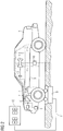
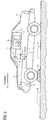
- FIG. 3 A shock absorber test using internal sensors 6 is shown.
- a vibration measurement is carried out after excitation by driving through an external physical excitation 13 in the form of a threshold, ramp or the like, by evaluating the decay behavior.
- the physical excitation 13 can also be carried out periodically by crossing a plurality of buckles 14 in order to resonate the vehicle body. Reaching the resonance depends, on the one hand, on the distance between the knuckles 14 and, on the other hand, the speed at which the vehicle 4 is crossing.
- the level of resonance allows statements to be made about the state of the axle damping.
- the vibration is recorded by means of a 3-axis acceleration and / or a 3-axis rotation rate sensor 6.
- the system is then evaluated for suitable vibration damper sizes, such as decay constant, damping factor or damping quality.
- the alignment of the adapter 1 in the car 4 itself is carried out by determining the gravitational acceleration vector and by the acceleration vector during the speed increase of the vehicle (positive acceleration).
- the values determined can be based on their quality or the assessability are classified. This is done by recognizing avoidable measuring errors or compensating for measuring errors using suitable mathematical methods. Such measurement errors can occur due to sloping driving, interference vibrations due to uneven road surface, incorrect calibration due to cornering or excessive speed. A clever evaluation is an axle or wheel specific Assignment or separation of the measured values possible.
- An advantage of the method according to the invention is the basic detectability of damage or defects on a large number of further vehicle assemblies, such as wheel suspension, spring damper mounting, springs and joints. In particular, a spring break can be seen. The method can also be used to detect and classify tire damage.
Landscapes
- Physics & Mathematics (AREA)
- General Physics & Mathematics (AREA)
- Measurement Of Mechanical Vibrations Or Ultrasonic Waves (AREA)
- Vehicle Body Suspensions (AREA)
Description
Die Erfindung betrifft ein Verfahren zur Baugruppenprüfung, bei dem eine Schwingung eines Fahrzeuges angeregt und Messdaten durch Messen des Beschleunigungs-, Verzögerungs- oder Schwingverhaltens mittels mindestens eines in das Fahrzeug eingebrachten und/oder mit dem Fahrzeug verbundenen Sensors erzeugt werden. Die Erfindung betrifft auch eine Anordnung zur Durchführung des Verfahrens mit einem Anregungsmittel zum Anregen einer Schwingung eines Fahrzeuges und einem Messmittel zum Messen des Beschleunigungs-, Verzögerungs- oder Schwingverhaltens mittels in das Fahrzeug eingebrachter und/oder mit dem Fahrzeug verbundener Sensoren.The invention relates to a method for component testing, in which a vibration of a vehicle is excited and measurement data are generated by measuring the acceleration, deceleration or vibration behavior by means of at least one sensor which is introduced into the vehicle and / or is connected to the vehicle. The invention also relates to an arrangement for carrying out the method with an excitation means for exciting a vibration of a vehicle and a measuring means for measuring the acceleration, deceleration or vibration behavior by means of sensors incorporated into the vehicle and / or connected to the vehicle.
Aus der
In der
In der
In der
Durch die beiden vorstehend genannten Verfahren werden Analysen von Schwingungen zur Beurteilung des Fahrkomforts durchgeführt. Eine Analyse der technischen Funktion von Fahrzeugbaugruppen, insbesondere zur Achsdämpfungsprüfung, ist durch diese Verfahren nicht möglich.The two methods mentioned above are used to analyze vibrations to assess driving comfort. An analysis of the technical function of vehicle assemblies, in particular for the axle damping test, is not possible with this method.
In
Es soll an dieser Stelle ausdrücklich betont werden, dass in der gesamten Beschreibung unter dem Begriff des Fahrzeuges jede Fahrzeugart, wie allgemein Kraftfahrzeuge oder Nutzfahrzeuge, Krafträder, Kraftfahrzeuganhänger usw., und der Kombinationen davon verstanden werden soll.At this point it should be expressly emphasized that in the entire description, the term vehicle should be understood to mean any type of vehicle, such as generally motor vehicles or commercial vehicles, motorcycles, motor vehicle trailers, etc., and the combinations thereof.
Es ist daher Aufgabe der vorliegenden Erfindung, ein Verfahren zur Baugruppenprüfung, insbesondere zur Achsdämpfungsprüfung bereitzustellen, das zuverlässig ist und sicher arbeitet.It is therefore an object of the present invention to provide a method for component testing, in particular for axle damping testing, which is reliable and works safely.
Diese Aufgabe wird durch ein Verfahren und eine Vorrichtung gemäß den unabhängigen Ansprüchen 1 und 8 gelöst. Die abhängigen Ansprüche 2 bis 7, 9 und 10 betreffen besondere Ausführungsformen.This object is achieved by a method and a device according to
Bei dem erfindungsgemäßen Verfahren wird ein Fahrzeug zum Schwingen angeregt. Das Beschleunigungs-, Verzögerungs- oder Schwingverhalten wird mittels mindestens eines in das Fahrzeug eingebrachten und/oder mit dem Fahrzeug verbundenen Sensors gemessen. Diese Messdaten werden mittels eines lernbasierten Klassifikationsalgorithmus ausgewertet. Dieser dient zur Klassifikation der Funktionalität von Achsdämpfern im Sinne von Gebrauchstauglichkeit. Hierbei wird ein Trainingssatz von Messdaten durch Messen des Beschleunigungs-, Verzögerungs- oder Schwingverhaltens in einer definierten Messumgebung für ein Fahrzeug und/oder einen Fahrzeugtyp erstellt. Mittels des Trainingssatzes von Messdaten und anhand bekannter Achsdämpfungsparameter wird der Klassifikationsalgorithmus trainiert. Ist das Training des Klassifikationsalgorithmus abgeschlossen, werden im laufenden Achsdämpfungsmessungsverfahren Messwerte mittels des Klassifikationsalgorithmus ausgewertet. Das Klassifikationsergebnis wird in Form einer dichotomen Entscheidung über den Funktionszustand des Achsdämpfers und/oder eines Degradationsgrades der Funktionalität des Achsdämpfers ausgegeben. Die Klassifikation kann auch mit einem bereitgestellten, bereits trainierten Klassifikationsalgorithmus erfolgen.In the method according to the invention, a vehicle is excited to vibrate. The acceleration, deceleration or vibration behavior is measured by means of at least one sensor that is introduced into the vehicle and / or connected to the vehicle. This measurement data is evaluated using a learning-based classification algorithm. This serves to classify the functionality of axle dampers in terms of usability. Here, a training set of measurement data is created by measuring the acceleration, deceleration or vibration behavior in a defined measurement environment for a vehicle and / or a vehicle type. The classification algorithm is trained using the training set of measurement data and on the basis of known axle damping parameters. Once the training of the classification algorithm has been completed, measured values are evaluated in the current axle damping measurement process using the classification algorithm. The classification result is in the form of a dichotomous decision about the functional state of the axle damper and / or a degree of degradation of the functionality of the Axle damper issued. The classification can also be done with a provided, already trained classification algorithm.
Es ist dabei auch möglich, dass der Trainingssatz mit klassifizierten Messdaten einer aktuellen Messung erweitert wird. Das Trainieren des Klassifikationsalgorithmus für die Klassifizierung nachfolgender Messdaten erfolgt dann mittes dieses erweiterten Trainingssatzes. Somit werden nicht nur initiale Messungen zum Trainieren genutzt, sondern auch die aktuellen Messungen selbst.It is also possible for the training set to be expanded with classified measurement data from a current measurement. The training of the classification algorithm for the classification of subsequent measurement data is then carried out using this extended training set. Thus, not only initial measurements are used for training, but also the current measurements themselves.
Ein weiterer Aspekt der Erfindung betrifft die Schwingungsanregung. Diese kann durch einmalige Anregung durch ein Hindernis wie eine Schwelle, ein Schlagloch oder eine Rampe erfolgen. Beim Überfahren des Hindernisses werden die Achsen einmalig zum Schwingen angeregt und der Schwingungsverlauf mittels Beschleunigungs- und/oder Drehratensensor aufgenommen. Des Weiteren kann die Schwingungsanregung periodisch erfolgen. Mehrere gleichartige Hindernisse, die in bestimmten Abständen zueinander folgen, werden überfahren. Hierbei wird eine Aussage über die Höhe der Schwingungsamplitude bei Resonanzfrequenz getroffen. Diese lässt wiederum Schlüsse auf die Dämpfung des Systems zu. Zudem kann die Schwingungsanregung beim Bremsen, insbesondere durch Verbindung von dynamischer Bremsprüfung und Dämpfungsprüfung erfolgen. Hierbei wird das Fahrzeug stark abgebremst, wobei das Fahrzeug einnickt. Wenn das Fahrzeug zum Stillstand gekommen ist, geht das Fahrzeug von der eingenickten Position in den Ruhezustand über. Dieser Übergang folgt einer gedämpften Schwingung. Die Schwingungsanregung kann auch stochastisch während normaler Fahrt erfolgen. Hierbei fährt der Prüfer über eine undefinierte Strecke über eine undefinierte Zeit. Der Schwingungsverlauf wird aufgenommen und bewertet. Mittels geeigneter Verfahren wird eine Aussage über die Güte der Dämpfer des Systems getroffen.Another aspect of the invention relates to vibration excitation. This can be done by a single stimulus from an obstacle such as a threshold, a pothole or a ramp. When driving over the obstacle, the axes are excited to vibrate once and the course of the vibration is recorded by means of an acceleration and / or rotation rate sensor. Furthermore, the vibration can be excited periodically. Several similar obstacles, which follow each other at certain intervals, are run over. Here, a statement is made about the level of the vibration amplitude at the resonance frequency. This in turn allows conclusions to be drawn about the damping of the system. In addition, the vibration can be excited when braking, in particular by combining the dynamic brake test and damping test. Here, the vehicle is braked sharply, causing the vehicle to nod. When the vehicle has come to a standstill, the vehicle changes from the dozed position to the idle state. This transition follows a damped oscillation. The vibration excitation can also be stochastic during normal driving. Here, the inspector drives over an undefined route over an undefined time. The course of the vibration is recorded and evaluated. A suitable method is used to make a statement about the quality of the system's dampers.
Die Klassifizierung der Messergebnisse kann vorzugsweise durch einen Vergleich mit bekannten fehlerfreien Messergebnismustern erfolgen.The measurement results can preferably be classified by comparison with known error-free measurement result patterns.
Ein Aspekt der Erfindung betrifft die Auswertung der Messdaten in Form einer Bewertung des Schwingverhaltens. Diese erfolgt vorzugsweise in Richtung der Erdbeschleunigung und in Querrichtung, anhand einzelner Schwingungsparameter wie Abklingkonstante, Dämpfungsgrad, Schwingungsdauer, Frequenz.One aspect of the invention relates to the evaluation of the measurement data in the form of an evaluation of the vibration behavior. This is preferably done in the direction of gravitational acceleration and in the transverse direction, using individual vibration parameters such as decay constant, degree of damping, period of oscillation, frequency.
In einer Ausgestaltung der Erfindung wird das Schwingverhalten im Zeitbereich gemessen. Die Klassifikation kann jedoch nach einer Transformation im Frequenzbereich erfolgen.In one embodiment of the invention, the vibration behavior is measured in the time domain. The classification can, however, take place after a transformation in the frequency domain.
Ein weiterer Aspekt der Erfindung betrifft die Ausrichtung des Sensors. Diese erfolgen numerisch anhand des Messens der Erdbeschleunigung im Stand und der Beschleunigung während einer Geschwindigkeitsänderung, vorzugsweise durch eine Koordinatentransformation.Another aspect of the invention relates to the alignment of the sensor. These are carried out numerically on the basis of measuring the acceleration due to gravity when stationary and the acceleration during a change in speed, preferably by means of a coordinate transformation.
Im Stand wird über eine Mittelwertbildung der Beschleunigungswerte, die im Koordinatensystem des Sensors SKS abgebildet sind, der Erdbeschleunigungsvektor ermittelt. Der Winkel zwischen diesem Vektor und dem Einheitsvektor in Richtung der Z-Achse und der Normalenvektor (Drehachse) zu der Ebene, die diese beiden Vektoren aufspannen, werden ermittelt. Daraus wird eine erste Rotationsmatrix berechnet und es entsteht ein zweites Koordinatensystem SKS*.In the stand, the gravitational acceleration vector is determined by averaging the acceleration values, which are shown in the coordinate system of the SKS sensor. The angle between this vector and the unit vector in the direction of the Z axis and the normal vector (axis of rotation) to the plane which these two vectors span are determined. A first rotation matrix is calculated from this and a second coordinate system SKS * is created.
Während der Geschwindigkeitsänderung wird der Fahrzeugbeschleunigungsvektor ermittelt, indem die in dem zweiten Koordinatensystem SKS* abgebildeten X- und Y-Werte jeweils gemittelt werden und der Winkel zwischen dem Vektor der Mittelwerte und dem Einheitsvektor in Richtung der X-Achse bestimmt wird. Mit dem Winkel und der Drehachse, die nun dem Einheitsvektor in Richtung der Z-Achse entspricht, kann eine zweite Rotationsmatrix berechnet werden, mit der das zweite Koordinatensystem SKS* in das Fahrzeugkoordinatensystem FKS überführt werden kann.During the speed change, the vehicle acceleration vector is determined by averaging the X and Y values shown in the second coordinate system SKS * and determining the angle between the vector of the mean values and the unit vector in the direction of the X axis. With the angle and the axis of rotation that now corresponds to the unit vector in the direction of the Z axis, a second rotation matrix can be calculated with which the second coordinate system SKS * can be converted into the vehicle coordinate system FKS.
Mittels Matrizenmultiplikation lassen sich die beiden Rotationsmatrizen kombinieren und die Beschleunigungs- und Drehraten-Rohdaten aus dem Koordinatensystem SKS können nun mittels der resultierenden Matrix direkt im Fahrzeugkoordinatensystem FKS abgebildet werden.The two rotation matrices can be combined by means of matrix multiplication, and the raw acceleration and rotation rate data from the SKS coordinate system can now be mapped directly in the vehicle coordinate system FKS using the resulting matrix.
Ein Aspekt der Erfindung betrifft die Auswertung von den mittels des Sensors gewonnenen Messwerten. Diese werden in Kombination mit weiteren mittels weiterer Sensoren gewonnener Messwerte, vorzugsweise des Bremsdruckes, bevorzugt in Hinblick auf die Plausibilität der gewonnenen Messergebnisse, analysiert.One aspect of the invention relates to the evaluation of the measured values obtained by means of the sensor. These are analyzed in combination with further measurement values obtained by means of further sensors, preferably the brake pressure, preferably with regard to the plausibility of the measurement results obtained.
In einer Ausgestaltung der Erfindung ist vorgesehen, dass die Messwerte gespeichert werden.One embodiment of the invention provides that the measured values are stored.
Durch eine Speicherung der Messwerte ist es möglich, diese nach Entfernen des Adapters aus dem Fahrzeug auszuwerten.By storing the measured values, it is possible to evaluate them after removing the adapter from the vehicle.
Es ist auch möglich, dass die Messwerte von dem Adapter über eine Schnittstelle an eine Auswerteeinheit übertragen werden.It is also possible for the measured values to be transmitted from the adapter to an evaluation unit via an interface.
Ein weiterer Aspekt der Erfindung betrifft die Schwingungsanregung. Hierbei wird die sich ergebende Schwingung auf vermeidbare Fehler wie schräges Auffahren und/oder fehlerhafte Kalibrierung und/oder eine unpassende, z.B. eine zu hohe oder zu geringe, Geschwindigkeit überprüft.Another aspect of the invention relates to vibration excitation. Here, the resulting vibration is based on avoidable errors such as skewed opening and / or incorrect calibration and / or an unsuitable, e.g. a too high or too low, speed checked.
Die anordnungsseitige Lösung der Aufgabenstellung besteht in einer Vorrichtung, welche Anregungsmittel zum Anregen einer Schwingung eines Fahrzeuges, Messmittel zum Messen des Beschleunigungs-, Verzögerungs- oder Schwingverhaltens mittels in das Fahrzeug eingebrachter und/oder mit dem Fahrzeug verbundener Sensoren und Auswertemittel zum Auswerten der Messdaten mittels des im Verfahren beschriebenen lernbasierten Klassifikationsalgorithmus aufweist. Dabei ist ein in ein Fahrzeug einbringbarer oder mit dem Fahrzeug verbindbarer Adapter mit einem 3-Achs-Beschleunigungs- und/oder eines 3-Achs-Drehratensensors versehen, der mit Mitteln zur Aufnahme von Messwerten verbunden ist.The arrangement-based solution of the task consists in a device which excitation means for exciting a vibration of a vehicle, measuring means for measuring the Has acceleration, deceleration or vibration behavior by means of sensors and evaluation means, which are introduced into the vehicle and / or connected to the vehicle, for evaluating the measurement data by means of the learning-based classification algorithm described in the method. In this case, an adapter that can be inserted into a vehicle or that can be connected to the vehicle is provided with a 3-axis acceleration and / or a 3-axis rotation rate sensor that is connected to means for recording measured values.
Durch die Integration eines Beschleunigungssensors, vorzugsweise ein 3-D-Beschleunigungssensor und/oder ein Drehratensensor, vorzugsweise ein 3-D-Drehratensensor in dem Adapter wird es möglich, mit dem Adapter physisch-dynamische Prüfungen, wie beispielsweise eine Bremsreferenzprüfung oder eine Aufbauschwingungsprüfung, durchzuführen.The integration of an acceleration sensor, preferably a 3-D acceleration sensor and / or a rotation rate sensor, preferably a 3-D rotation rate sensor, in the adapter makes it possible to carry out physical-dynamic tests, such as a brake reference test or a structural vibration test, with the adapter .
Eine weitere Möglichkeit der Nutzungserweiterung besteht darin, dass für den Adapter externe Sensoren abgefragt werden. Damit wird es möglich, fahrzeuginterne Sensoren, insbesondere über den Fahrzeug-Kommunikationsbus abzufragen. Aber auch Werte von externen Diagnoseeinrichtungen oder externer Prüfstände oder Sensoren können auf den Adapter übertragen werden. Hierfür bieten sich herkömmliche drahtlose Verbindungen, wie WLAN UMTS oder Bluetooth an. Aber auch eine Drahtverbindung, beispielsweise über USB oder LAN ist hierbei möglich.Another option for extending the use is to query external sensors for the adapter. This makes it possible to query sensors inside the vehicle, in particular via the vehicle communication bus. But values from external diagnostic devices or external test benches or sensors can also be transferred to the adapter. Conventional wireless connections such as WLAN UMTS or Bluetooth are suitable for this. A wire connection, for example via USB or LAN, is also possible.
Somit wird es auch möglich, beispielsweise zur Überprüfung eines Geräuschspegels oder einer bestimmter Geräuschkulisse im Fahrgastraum oder außerhalb dessen ein Mikrophon als externern Sensor an den Adapter anzuschließen. Beispielsweise können aufgenommene aktuelle Geräuschbilder zum Vergleich mit Soll-Geräuschbildern verwendet werden. Abweichungen beider Geräuschbilder voneinander sind meist signifikant für bestimmte Fehler- oder Verschleißarten oder falsche Bauteile, wie beispielsweise nicht zugelassene Schalldämpfer. Mit dem Adapter kann damit auch ein Hinweis auf Fehler oder Verschleißzustände oder nicht zulässige Bauteile gewonnen werden.It is therefore also possible to connect a microphone as an external sensor to the adapter, for example for checking a noise level or a specific background noise in the passenger compartment or outside of it. For example, recorded current noise images can be used for comparison with target noise images. Deviations of the two noise patterns from each other are usually significant for certain types of errors or wear or wrong components, such as mufflers that are not approved. The adapter can also be used to provide information on errors or wear conditions or impermissible components.
Um zu vermeiden, dass der Adapter von der Bordspannung abhängig ist, ist es zweckmäßig, den Adapter mit einer eigenen Stromversorgung zu versehen.In order to avoid that the adapter is dependent on the on-board voltage, it is advisable to provide the adapter with its own power supply.
Die Erfindung soll nachfolgend anhand eines Ausführungsbeispieles näher erläutert werden.The invention will be explained in more detail below using an exemplary embodiment.
In den zugehörigen Zeichnungen zeigt
- Fig. 1
- eine schematische Darstellung einer dynamischen Bremsenprüfung mit adaptereigenen Sensoren,
- Fig. 2
- eine schematische Darstellung einer quasistatischen Bremsenprüfung und
- Fig. 3
- eine schematische Darstellung einer Stoßdämpferprüfung mit dem Adapter.
- Fig. 1
- a schematic representation of a dynamic brake test with adapter-specific sensors,
- Fig. 2
- a schematic representation of a quasi-static brake test and
- Fig. 3
- a schematic representation of a shock absorber test with the adapter.
Zur Ermittlung der Funktionsfähigkeit mechanischer Baugruppen in einem Fahrzeug 4, wie Bremssystem oder Stoßdämpfer wird erfindungsgemäß ein Adapter 1 vorgeschlagen, der mit einem 3-Achs-Beschleunigungs- und/oder einem 3-Achs-Drehratensensor 6 versehen ist. Damit wird es möglich, Beschleunigungen, Verzögerung und Schwingungen im Fahrzeug aufzunehmen, wie dies nachfolgend beispielhaft geschildert wird. Der Adapter erhält seinen Namen, da er gegebenenfalls auch über eine geeignete Schnittstelle, beispielsweise eine Fahrzeug-Diagnoseschnittstelle 2 mit einem Fahrzeugbus 5 verbindbar ist.To determine the functionality of mechanical assemblies in a
Wie in
Bei einer dynamischen Bremsenprüfung, wie in
Gleichzeitig wird die adapterinterne Sensorik genutzt, nämlich der 3D-Beschleunigungssensor 6, um die Verzögerung des Fahrzeugs 4 zu ermitteln.At the same time, the adapter-internal sensor system, namely the
Durch Auswertung und Vergleich des adapterinternen Sensors 6 mit den fahrzeugintern gemessenen Werten können nun Rückschlüsse über die Wirkung der Bremse getroffen werden.By evaluating and comparing the
Bei einer quasistatischen Bremsenprüfung, wie in
Gleichzeitig nutzt der Adapter 1 während der Bremsung die fahrzeuginterne Sensorik 7 und liest den Bremsdruck im Fahrzeug 4 kontinuierlich aus. Dies geschieht durch Absenden eines Abfragebefehls und Auswerten des jeweiligen Reaktionssignals.At the same time, the adapter 1 uses the in-
Durch Auswertung und Vergleich der fahrzeugexternen Messung mit den fahrzeugintern gemessenen Werten können nun Rückschlüsse über die Wirkung der Bremse getroffen werden.By evaluating and comparing the measurement outside the vehicle with the values measured inside the vehicle, you can now Conclusions about the effect of the brake can be made.
In
Die Höhe der Resonanz lässt Aussagen zum Zustand der Achsdämpfung zu.The level of resonance allows statements to be made about the state of the axle damping.
Dazu wird die Schwingung mittels eines 3-Achs-Beschleunigungs- und/oder eines 3-Achs-Drehratensensors 6 aufgenommen. Das System wird sodann geeigneter Schwingungsdämpfergrößen, wie beispielsweise Abklingkonstante, Dämpfungsmaß oder Dämpfungs-Güte bewertet.For this purpose, the vibration is recorded by means of a 3-axis acceleration and / or a 3-axis
Die Ausrichtung des Adapters 1 im Auto 4 selbst erfolgt mittels Ermittlung des Erdbeschleunigungsvektors und durch den Beschleunigungsvektor, während der Geschwindigkeitserhöhung des Fahrzeugs (positive Beschleunigung).The alignment of the adapter 1 in the
Die ermittelten Werte können hinsichtlich ihrer Güte bwz. der Bewertbarkeit klassifiziert werden. Dies geschieht durch die Erkennung von vermeidbaren Messfehlern oder einer Kompensation von Messfehlern durch geeignete mathematische Verfahren. Solche Messfehler können durch schräges Auffahren, durch Störschwingungen auf Grund von unebener Fahrbahn, durch eine Fehlkalibrierung wegen Kurvenanfahrt oder durch zu hohe Geschwindigkeit auftreten. Über eine geschickte Auswertung ist eine achs- oder radspezifische Zuordnung oder eine Trennung der Messwerte möglich. Vorteil des erfindungsgemäßen Verfahrens ist die prinzipielle Detektierbarkeit von Schäden oder Defekten an einer Vielzahl weiterer Fahrzeugbaugruppen wie Radaufhängung, Federdämpferlagerung, Federn und Gelenke. Insbesondere ist ein Federbruch erkennbar. Zudem kann das Verfahren dazu verwendet werden, Reifenschäden zu detektieren und klassifizieren.The values determined can be based on their quality or the assessability are classified. This is done by recognizing avoidable measuring errors or compensating for measuring errors using suitable mathematical methods. Such measurement errors can occur due to sloping driving, interference vibrations due to uneven road surface, incorrect calibration due to cornering or excessive speed. A clever evaluation is an axle or wheel specific Assignment or separation of the measured values possible. An advantage of the method according to the invention is the basic detectability of damage or defects on a large number of further vehicle assemblies, such as wheel suspension, spring damper mounting, springs and joints. In particular, a spring break can be seen. The method can also be used to detect and classify tire damage.
- 11
- Adapteradapter
- 22nd
- Fahrzeug-Diagnose-SchnittstelleVehicle diagnostic interface
- 33rd
- SteuergerätControl unit
- 44th
- Fahrzeugvehicle
- 55
- Busbus
- 66
- 3-D-Beschleunigungssensor (adapterinterner Sensor)3-D acceleration sensor (adapter-internal sensor)
- 77
- Steuergerät, das den Bremsdruck kontrolliertControl unit that controls the brake pressure
- 88th
- BremsleitungBrake line
- 99
- BremsenprüfstandBrake test bench
- 1010th
- Schnittstelle externer Sensor / AdapterInterface external sensor / adapter
- 1111
- DatenanzeigeleitungData display line
- 1212th
- AnzeigeeinrichtungDisplay device
- 1313
- physische Erregungphysical arousal
- 1414
- HuckelHuckel
Claims (10)
- Method for checking components, in which- an adapter (1) with at least one adapter-internal sensor (6) is introduced into a vehicle (4) and connected to a vehicle communication bus (5) of the vehicle (4) via a vehicle-diagnostic interface (2),- the adapter-internal sensor (6) is numerically aligned on the basis of measurement of the acceleration due to gravity in a stationary state and acceleration during a change in speed,- an oscillation of the vehicle (4) is excited, and measurement data are generated by measuring the acceleration, deceleration or oscillatory behaviour, by means of the adapter-internal sensor (6),- a combination of the measured values acquired by means of the adapter-internal sensor (6) and further measured values acquired by means of adapter-external sensors (3; 7; 9) are analysed with the respect to the plausibility of the acquired measurement results,- a learning-based classification algorithm is made available by virtue of the fact that a training set of measurement data is produced by measuring the acceleration, deceleration or oscillatory behaviour in a defined measuring environment for a vehicle and/or a type of vehicle, and the classification algorithm is trained by means of the training set of measurement data and on the basis of known axle damping parameters;- the measurement data are classified by means of the classification algorithm which is trained in this way; and- the classification result is output in the form of a dichotomous decision about the functional state of the axle damper and/or a degree of degradation of the functionality of the axle damper.
- Method according to Claim 1, which comprises:expanding the training set with classified measurement data from a current measurement; andtraining the classification algorithm for the classification of subsequent measurement data.
- Method according to Claim 1 or 2, which comprises:
exciting the oscillation with the vehicle by means of an obstacle or periodically by means of obstacles (14) which follow at specific intervals, or by means of pitching during braking or stochastically by means of travel over an undefined distance and an undefined time. - Method according to one of Claims 1 to 3, which comprises:
evaluating the measurement data in the form of an evaluation of the oscillatory behaviour, preferably in the direction of the acceleration due to gravity and in the transverse direction, on the basis of individual oscillation parameters such as the decay constant, degree of damping, duration of oscillation and the frequency. - Method according to one of Claims 1 to 4, which comprises:measuring the oscillatory behaviour in the time domain andclassifying the oscillatory behaviour in the frequency domain.
- Method according to one of Claims 1 to 5, which comprises:
storing the measurement data. - Method according to one of Claims 1 to 6, which comprises:
checking the oscillation for avoidable faults such as oblique approaching from behind and/or faulty calibration and/or unadapted speed. - Device for carrying out a method according to one of Claims 1 to 7,- having an excitation means (13; 14) for exciting an oscillation of a vehicle (4), and- having an adapter (1) which is connected via a vehicle diagnostic interface (2) to a vehicle communication bus (5) of the vehicle (4) and to adapter-external sensors (3; 7; 9) and which comprises the following:- a measuring means for measuring the acceleration, deceleration or oscillatory behaviour by means of adapter-internal sensors (6) which are introduced into the vehicle, and- having an evaluation means for evaluating the measurement data by means of the learning-based classification algorithm, wherein the evaluation means is configured to carry out the method according to one of Claims 1 to 7, wherein- the measuring means is embodied as an adapter-internal sensor (6) which is introduced into the vehicle and is connected to means for recording measured values and which comprises an acceleration sensor and/or rotational speed sensor.
- Device according to Claim 8, characterized in that the adapter (1) is connected to adapter-external sensors (9) in a wireless fashion, in particular via WLAN, UMTS or Bluetooth.
- Device according to Claim 8, characterized in that the adapter is connected to adapter-external sensors (9) via USB or LAN.
Priority Applications (1)
| Application Number | Priority Date | Filing Date | Title |
|---|---|---|---|
| PL12158992T PL2500708T3 (en) | 2011-03-16 | 2012-03-12 | Device and method for checking components, in particular axle suspension testing, in vehicles |
Applications Claiming Priority (2)
| Application Number | Priority Date | Filing Date | Title |
|---|---|---|---|
| DE102011005628 | 2011-03-16 | ||
| DE102012200194A DE102012200194A1 (en) | 2011-03-16 | 2012-01-09 | Arrangement and method for module testing, in particular for Achsdämpfungsprüfung, in vehicles |
Publications (2)
| Publication Number | Publication Date |
|---|---|
| EP2500708A1 EP2500708A1 (en) | 2012-09-19 |
| EP2500708B1 true EP2500708B1 (en) | 2020-05-06 |
Family
ID=45992030
Family Applications (1)
| Application Number | Title | Priority Date | Filing Date |
|---|---|---|---|
| EP12158992.3A Active EP2500708B1 (en) | 2011-03-16 | 2012-03-12 | Device and method for checking components, in particular axle suspension testing, in vehicles |
Country Status (6)
| Country | Link |
|---|---|
| EP (1) | EP2500708B1 (en) |
| DE (1) | DE102012200194A1 (en) |
| ES (1) | ES2804054T3 (en) |
| LT (1) | LT2500708T (en) |
| PL (1) | PL2500708T3 (en) |
| PT (1) | PT2500708T (en) |
Families Citing this family (9)
| Publication number | Priority date | Publication date | Assignee | Title |
|---|---|---|---|---|
| DE102012221491A1 (en) * | 2012-11-23 | 2014-05-28 | Brt Automotive Gmbh & Co Kg | Measuring arrangement for examining undercarriages of e.g. passenger car, has sensor for transmitting and/or processing measured data that is connected with computer and has internal memory for temporarily storing measurement data |
| DE102013112976A1 (en) * | 2013-09-30 | 2015-04-02 | Hochschule für Technik und Wirtschaft Dresden | Arrangement and method for determining the chassis and other characteristics of a vehicle |
| CN104021375B (en) * | 2014-05-29 | 2017-11-07 | 银江股份有限公司 | A kind of model recognizing method based on machine learning |
| DE102014226490A1 (en) * | 2014-12-18 | 2016-06-23 | Volkswagen Aktiengesellschaft | Device and method for reporting an extraordinary stress on a chassis of a means of transportation |
| DE102014119393B3 (en) | 2014-12-22 | 2016-05-12 | Fsd Fahrzeugsystemdaten Gmbh | Method and device for determining dynamic wheel contact force |
| DE102015014840B4 (en) * | 2015-11-14 | 2021-12-16 | Audi Ag | Method for testing an electric parking brake, replacement disc and measuring adapter |
| US10275955B2 (en) * | 2016-03-25 | 2019-04-30 | Qualcomm Incorporated | Methods and systems for utilizing information collected from multiple sensors to protect a vehicle from malware and attacks |
| DE102020204918A1 (en) | 2020-04-17 | 2021-10-21 | Zf Friedrichshafen Ag | Procedure for checking a landing gear |
| DE102022209307B4 (en) | 2022-09-07 | 2023-08-03 | Zf Friedrichshafen Ag | Methods for condition monitoring |
Citations (6)
| Publication number | Priority date | Publication date | Assignee | Title |
|---|---|---|---|---|
| DE4019501A1 (en) * | 1989-09-30 | 1991-04-11 | Lehn F Heinrich | METHOD AND DEVICE FOR VIBRATION MONITORING OF THE WHEEL SYSTEMS OF MOTOR VEHICLES DURING DRIVING |
| DE4440413A1 (en) * | 1994-11-11 | 1996-05-15 | Fichtel & Sachs Ag | Monitoring system for determining efficiency of esp. motor vehicle shock absorber |
| DE19814357A1 (en) * | 1998-03-31 | 1999-10-07 | Maha Gmbh & Co Kg | Measuring device for vehicle diagnosis |
| WO2004024521A1 (en) * | 2002-08-27 | 2004-03-25 | Continental Teves Ag & Co. Ohg | Method for monitoring chassis functions and chassis components |
| DE10320809A1 (en) * | 2003-05-08 | 2004-11-25 | Conti Temic Microelectronic Gmbh | Car motion recognition and monitoring procedure processes data from acceleration, speed, force and body noise sensors using pattern recognition based on state vectors |
| US20110054733A1 (en) * | 2009-08-28 | 2011-03-03 | Hyundai Motor Company | Gravity sensor circuit system for vehicle |
Family Cites Families (6)
| Publication number | Priority date | Publication date | Assignee | Title |
|---|---|---|---|---|
| JP3518238B2 (en) * | 1997-03-31 | 2004-04-12 | 株式会社豊田中央研究所 | Ride comfort evaluation device |
| DE19850079A1 (en) | 1998-10-30 | 2000-05-11 | Bosch Gmbh Robert | Method and arrangement for brake testing by means of deceleration measurement in motor vehicles |
| DE60014913T2 (en) * | 1999-07-13 | 2006-03-09 | Société de Technologie Michelin | METHOD FOR FORECASTING THE COMFORT OF A VEHICLE EQUIPPED WITH A GROUND CONNECTION SYSTEM |
| DE10258265A1 (en) | 2002-01-25 | 2003-08-21 | Continental Teves Ag & Co Ohg | Monitoring of a motor vehicle shock absorber system to detect abnormal behavior by comparison of the recorded attenuation behavior or frequency of a shock absorber with theoretical values to indicate a problem or otherwise |
| DE102004012143B3 (en) | 2004-03-12 | 2005-09-15 | Audi Ag | A method of testing the function of electronic and electrical components mounted in a motor vehicle of a particular type, addressable via a communications bus |
| DE202006019993U1 (en) | 2006-07-13 | 2007-07-12 | Berger Elektronik Ing.-Büro und Vertriebs GmbH | Mobile diagnostic device for vehicles comprises a data storage unit for storing scanned diagnostic data, a warning unit for producing a warning signal and an interface for producing a data connection with a data processing unit |
-
2012
- 2012-01-09 DE DE102012200194A patent/DE102012200194A1/en not_active Ceased
- 2012-03-12 LT LTEP12158992.3T patent/LT2500708T/en unknown
- 2012-03-12 EP EP12158992.3A patent/EP2500708B1/en active Active
- 2012-03-12 ES ES12158992T patent/ES2804054T3/en active Active
- 2012-03-12 PT PT121589923T patent/PT2500708T/en unknown
- 2012-03-12 PL PL12158992T patent/PL2500708T3/en unknown
Patent Citations (6)
| Publication number | Priority date | Publication date | Assignee | Title |
|---|---|---|---|---|
| DE4019501A1 (en) * | 1989-09-30 | 1991-04-11 | Lehn F Heinrich | METHOD AND DEVICE FOR VIBRATION MONITORING OF THE WHEEL SYSTEMS OF MOTOR VEHICLES DURING DRIVING |
| DE4440413A1 (en) * | 1994-11-11 | 1996-05-15 | Fichtel & Sachs Ag | Monitoring system for determining efficiency of esp. motor vehicle shock absorber |
| DE19814357A1 (en) * | 1998-03-31 | 1999-10-07 | Maha Gmbh & Co Kg | Measuring device for vehicle diagnosis |
| WO2004024521A1 (en) * | 2002-08-27 | 2004-03-25 | Continental Teves Ag & Co. Ohg | Method for monitoring chassis functions and chassis components |
| DE10320809A1 (en) * | 2003-05-08 | 2004-11-25 | Conti Temic Microelectronic Gmbh | Car motion recognition and monitoring procedure processes data from acceleration, speed, force and body noise sensors using pattern recognition based on state vectors |
| US20110054733A1 (en) * | 2009-08-28 | 2011-03-03 | Hyundai Motor Company | Gravity sensor circuit system for vehicle |
Also Published As
| Publication number | Publication date |
|---|---|
| DE102012200194A1 (en) | 2012-09-20 |
| PL2500708T3 (en) | 2020-12-28 |
| ES2804054T3 (en) | 2021-02-02 |
| EP2500708A1 (en) | 2012-09-19 |
| PT2500708T (en) | 2020-07-07 |
| LT2500708T (en) | 2020-10-26 |
Similar Documents
| Publication | Publication Date | Title |
|---|---|---|
| EP2500708B1 (en) | Device and method for checking components, in particular axle suspension testing, in vehicles | |
| DE102017112322B4 (en) | Computer-implemented method and device for autonomously monitoring the health of a vehicle | |
| DE102018123821A1 (en) | SYSTEMS AND METHOD FOR DETECTING INTERFERENCE IN A VEHICLE SUSPENSION SYSTEM | |
| WO2016102377A1 (en) | System and method for determining at least one tyre contact area parameter characterising a dimension of a tyre contact area on a tyre of a wheel of a vehicle | |
| DE102014113669A1 (en) | Method for determining the state in a rail vehicle | |
| DE10020521A1 (en) | Method and device for monitoring the driving behavior of rail vehicles | |
| DE102008053005A1 (en) | Method and system for influencing the movement of a controllable in his movements vehicle structure of a motor vehicle and vehicle | |
| DE102012218426B4 (en) | Method, control unit and system for determining a, a state of at least one component of a motor vehicle characterizing parameter | |
| EP2101156B1 (en) | Method and device for monitoring undercarriage regulation systems | |
| EP3052919A1 (en) | Arrangement and method for ascertaining chassis properties and other properties of a vehicle | |
| DE102010038971A1 (en) | Method and device for evaluating a state of a chassis of a vehicle | |
| EP2132548B1 (en) | Arrangement and method for determining and/or evaluating bodies and/or structures moved by vibrations and/or having a drive | |
| EP2801487A1 (en) | Draw bar with an evaluation device | |
| DE102017221891B4 (en) | Method for determining damage that occurs to the vehicle in an accident between a vehicle and a collision partner | |
| DE102012219762A1 (en) | Method for evaluating state of shock absorber of vehicle, particularly motor vehicle, involves detecting body movement of vehicle generated by road surface unevenness by sensor and determining position of unevenness using navigation system | |
| DE102018132952A1 (en) | METHOD AND DEVICE FOR FACILITATING A TIRE EQUIPMENT | |
| DE10062602B4 (en) | Method and device for monitoring the behavior of rail vehicles and for diagnosing components of rail vehicles | |
| DE102020211410A1 (en) | Method for operating a weight recording system for a motor vehicle or a trailer, corresponding weight recording system and motor vehicle and trailer | |
| DE102018113462B4 (en) | A method for detecting a defective damper device of a vehicle | |
| DE10337212B4 (en) | System and method for determining a loading state of a vehicle or a trailer | |
| DE102015223970B4 (en) | Method and device for determining a wheel load on a vehicle wheel | |
| WO2018210482A1 (en) | Method and device for accident detection in a vehicle | |
| DE102015214987B4 (en) | Determination of a defective component of a vehicle | |
| DE102014214995A1 (en) | Method, device and system for operating a motor vehicle | |
| DE102017121865A1 (en) | Method for monitoring the load of a chassis component when driving with a motor vehicle and motor vehicle |
Legal Events
| Date | Code | Title | Description |
|---|---|---|---|
| PUAI | Public reference made under article 153(3) epc to a published international application that has entered the european phase |
Free format text: ORIGINAL CODE: 0009012 |
|
| AK | Designated contracting states |
Kind code of ref document: A1 Designated state(s): AL AT BE BG CH CY CZ DE DK EE ES FI FR GB GR HR HU IE IS IT LI LT LU LV MC MK MT NL NO PL PT RO RS SE SI SK SM TR |
|
| AX | Request for extension of the european patent |
Extension state: BA ME |
|
| RAP1 | Party data changed (applicant data changed or rights of an application transferred) |
Owner name: FSD FAHRZEUGSYSTEMDATEN GMBH |
|
| 17P | Request for examination filed |
Effective date: 20130319 |
|
| 17Q | First examination report despatched |
Effective date: 20160308 |
|
| GRAP | Despatch of communication of intention to grant a patent |
Free format text: ORIGINAL CODE: EPIDOSNIGR1 |
|
| STAA | Information on the status of an ep patent application or granted ep patent |
Free format text: STATUS: GRANT OF PATENT IS INTENDED |
|
| INTG | Intention to grant announced |
Effective date: 20191126 |
|
| GRAS | Grant fee paid |
Free format text: ORIGINAL CODE: EPIDOSNIGR3 |
|
| RIN1 | Information on inventor provided before grant (corrected) |
Inventor name: USSATH, ROBERT Inventor name: BOENNINGER, JUERGEN Inventor name: STERNBERG, VOLKER Inventor name: DRECHSEL, FRANK |
|
| GRAA | (expected) grant |
Free format text: ORIGINAL CODE: 0009210 |
|
| STAA | Information on the status of an ep patent application or granted ep patent |
Free format text: STATUS: THE PATENT HAS BEEN GRANTED |
|
| AK | Designated contracting states |
Kind code of ref document: B1 Designated state(s): AL AT BE BG CH CY CZ DE DK EE ES FI FR GB GR HR HU IE IS IT LI LT LU LV MC MK MT NL NO PL PT RO RS SE SI SK SM TR |
|
| REG | Reference to a national code |
Ref country code: GB Ref legal event code: FG4D Free format text: NOT ENGLISH |
|
| REG | Reference to a national code |
Ref country code: AT Ref legal event code: REF Ref document number: 1267556 Country of ref document: AT Kind code of ref document: T Effective date: 20200515 Ref country code: CH Ref legal event code: EP |
|
| REG | Reference to a national code |
Ref country code: DE Ref legal event code: R096 Ref document number: 502012016044 Country of ref document: DE |
|
| REG | Reference to a national code |
Ref country code: IE Ref legal event code: FG4D Free format text: LANGUAGE OF EP DOCUMENT: GERMAN |
|
| REG | Reference to a national code |
Ref country code: PT Ref legal event code: SC4A Ref document number: 2500708 Country of ref document: PT Date of ref document: 20200707 Kind code of ref document: T Free format text: AVAILABILITY OF NATIONAL TRANSLATION Effective date: 20200630 |
|
| REG | Reference to a national code |
Ref country code: NL Ref legal event code: FP |
|
| REG | Reference to a national code |
Ref country code: SE Ref legal event code: TRGR |
|
| REG | Reference to a national code |
Ref country code: EE Ref legal event code: FG4A Ref document number: E019494 Country of ref document: EE Effective date: 20200714 |
|
| PG25 | Lapsed in a contracting state [announced via postgrant information from national office to epo] |
Ref country code: FI Free format text: LAPSE BECAUSE OF FAILURE TO SUBMIT A TRANSLATION OF THE DESCRIPTION OR TO PAY THE FEE WITHIN THE PRESCRIBED TIME-LIMIT Effective date: 20200506 Ref country code: NO Free format text: LAPSE BECAUSE OF FAILURE TO SUBMIT A TRANSLATION OF THE DESCRIPTION OR TO PAY THE FEE WITHIN THE PRESCRIBED TIME-LIMIT Effective date: 20200806 Ref country code: GR Free format text: LAPSE BECAUSE OF FAILURE TO SUBMIT A TRANSLATION OF THE DESCRIPTION OR TO PAY THE FEE WITHIN THE PRESCRIBED TIME-LIMIT Effective date: 20200807 Ref country code: IS Free format text: LAPSE BECAUSE OF FAILURE TO SUBMIT A TRANSLATION OF THE DESCRIPTION OR TO PAY THE FEE WITHIN THE PRESCRIBED TIME-LIMIT Effective date: 20200906 |
|
| PG25 | Lapsed in a contracting state [announced via postgrant information from national office to epo] |
Ref country code: BG Free format text: LAPSE BECAUSE OF FAILURE TO SUBMIT A TRANSLATION OF THE DESCRIPTION OR TO PAY THE FEE WITHIN THE PRESCRIBED TIME-LIMIT Effective date: 20200806 Ref country code: RS Free format text: LAPSE BECAUSE OF FAILURE TO SUBMIT A TRANSLATION OF THE DESCRIPTION OR TO PAY THE FEE WITHIN THE PRESCRIBED TIME-LIMIT Effective date: 20200506 Ref country code: HR Free format text: LAPSE BECAUSE OF FAILURE TO SUBMIT A TRANSLATION OF THE DESCRIPTION OR TO PAY THE FEE WITHIN THE PRESCRIBED TIME-LIMIT Effective date: 20200506 |
|
| PG25 | Lapsed in a contracting state [announced via postgrant information from national office to epo] |
Ref country code: AL Free format text: LAPSE BECAUSE OF FAILURE TO SUBMIT A TRANSLATION OF THE DESCRIPTION OR TO PAY THE FEE WITHIN THE PRESCRIBED TIME-LIMIT Effective date: 20200506 |
|
| PG25 | Lapsed in a contracting state [announced via postgrant information from national office to epo] |
Ref country code: SM Free format text: LAPSE BECAUSE OF FAILURE TO SUBMIT A TRANSLATION OF THE DESCRIPTION OR TO PAY THE FEE WITHIN THE PRESCRIBED TIME-LIMIT Effective date: 20200506 Ref country code: RO Free format text: LAPSE BECAUSE OF FAILURE TO SUBMIT A TRANSLATION OF THE DESCRIPTION OR TO PAY THE FEE WITHIN THE PRESCRIBED TIME-LIMIT Effective date: 20200506 Ref country code: DK Free format text: LAPSE BECAUSE OF FAILURE TO SUBMIT A TRANSLATION OF THE DESCRIPTION OR TO PAY THE FEE WITHIN THE PRESCRIBED TIME-LIMIT Effective date: 20200506 |
|
| REG | Reference to a national code |
Ref country code: ES Ref legal event code: FG2A Ref document number: 2804054 Country of ref document: ES Kind code of ref document: T3 Effective date: 20210202 |
|
| REG | Reference to a national code |
Ref country code: DE Ref legal event code: R097 Ref document number: 502012016044 Country of ref document: DE |
|
| PG25 | Lapsed in a contracting state [announced via postgrant information from national office to epo] |
Ref country code: SK Free format text: LAPSE BECAUSE OF FAILURE TO SUBMIT A TRANSLATION OF THE DESCRIPTION OR TO PAY THE FEE WITHIN THE PRESCRIBED TIME-LIMIT Effective date: 20200506 |
|
| PLBE | No opposition filed within time limit |
Free format text: ORIGINAL CODE: 0009261 |
|
| STAA | Information on the status of an ep patent application or granted ep patent |
Free format text: STATUS: NO OPPOSITION FILED WITHIN TIME LIMIT |
|
| 26N | No opposition filed |
Effective date: 20210209 |
|
| PG25 | Lapsed in a contracting state [announced via postgrant information from national office to epo] |
Ref country code: SI Free format text: LAPSE BECAUSE OF FAILURE TO SUBMIT A TRANSLATION OF THE DESCRIPTION OR TO PAY THE FEE WITHIN THE PRESCRIBED TIME-LIMIT Effective date: 20200506 |
|
| PG25 | Lapsed in a contracting state [announced via postgrant information from national office to epo] |
Ref country code: MC Free format text: LAPSE BECAUSE OF FAILURE TO SUBMIT A TRANSLATION OF THE DESCRIPTION OR TO PAY THE FEE WITHIN THE PRESCRIBED TIME-LIMIT Effective date: 20200506 |
|
| PG25 | Lapsed in a contracting state [announced via postgrant information from national office to epo] |
Ref country code: LU Free format text: LAPSE BECAUSE OF NON-PAYMENT OF DUE FEES Effective date: 20210312 |
|
| PGFP | Annual fee paid to national office [announced via postgrant information from national office to epo] |
Ref country code: FR Payment date: 20230320 Year of fee payment: 12 |
|
| PG25 | Lapsed in a contracting state [announced via postgrant information from national office to epo] |
Ref country code: HU Free format text: LAPSE BECAUSE OF FAILURE TO SUBMIT A TRANSLATION OF THE DESCRIPTION OR TO PAY THE FEE WITHIN THE PRESCRIBED TIME-LIMIT; INVALID AB INITIO Effective date: 20120312 Ref country code: CY Free format text: LAPSE BECAUSE OF FAILURE TO SUBMIT A TRANSLATION OF THE DESCRIPTION OR TO PAY THE FEE WITHIN THE PRESCRIBED TIME-LIMIT Effective date: 20200506 |
|
| PGFP | Annual fee paid to national office [announced via postgrant information from national office to epo] |
Ref country code: TR Payment date: 20230310 Year of fee payment: 12 Ref country code: SE Payment date: 20230315 Year of fee payment: 12 Ref country code: PL Payment date: 20230227 Year of fee payment: 12 Ref country code: LV Payment date: 20230317 Year of fee payment: 12 Ref country code: BE Payment date: 20230321 Year of fee payment: 12 |
|
| P01 | Opt-out of the competence of the unified patent court (upc) registered |
Effective date: 20230530 |
|
| PGFP | Annual fee paid to national office [announced via postgrant information from national office to epo] |
Ref country code: IT Payment date: 20230331 Year of fee payment: 12 Ref country code: ES Payment date: 20230414 Year of fee payment: 12 Ref country code: CH Payment date: 20230402 Year of fee payment: 12 |
|
| PGFP | Annual fee paid to national office [announced via postgrant information from national office to epo] |
Ref country code: LT Payment date: 20240229 Year of fee payment: 13 |
|
| PGFP | Annual fee paid to national office [announced via postgrant information from national office to epo] |
Ref country code: NL Payment date: 20240320 Year of fee payment: 13 Ref country code: IE Payment date: 20240319 Year of fee payment: 13 |
|
| PGFP | Annual fee paid to national office [announced via postgrant information from national office to epo] |
Ref country code: AT Payment date: 20240318 Year of fee payment: 13 |
|
| PG25 | Lapsed in a contracting state [announced via postgrant information from national office to epo] |
Ref country code: MK Free format text: LAPSE BECAUSE OF FAILURE TO SUBMIT A TRANSLATION OF THE DESCRIPTION OR TO PAY THE FEE WITHIN THE PRESCRIBED TIME-LIMIT Effective date: 20200506 |
|
| PGFP | Annual fee paid to national office [announced via postgrant information from national office to epo] |
Ref country code: EE Payment date: 20240315 Year of fee payment: 13 Ref country code: DE Payment date: 20240328 Year of fee payment: 13 Ref country code: CZ Payment date: 20240229 Year of fee payment: 13 Ref country code: GB Payment date: 20240322 Year of fee payment: 13 Ref country code: PT Payment date: 20240305 Year of fee payment: 13 |