EP2500685A1 - Confocal measurement device - Google Patents
Confocal measurement device Download PDFInfo
- Publication number
- EP2500685A1 EP2500685A1 EP12155695A EP12155695A EP2500685A1 EP 2500685 A1 EP2500685 A1 EP 2500685A1 EP 12155695 A EP12155695 A EP 12155695A EP 12155695 A EP12155695 A EP 12155695A EP 2500685 A1 EP2500685 A1 EP 2500685A1
- Authority
- EP
- European Patent Office
- Prior art keywords
- lens
- light
- confocal
- measurement device
- objective lens
- Prior art date
- Legal status (The legal status is an assumption and is not a legal conclusion. Google has not performed a legal analysis and makes no representation as to the accuracy of the status listed.)
- Granted
Links
- 238000005259 measurement Methods 0.000 title claims abstract description 170
- 230000003287 optical effect Effects 0.000 claims abstract description 88
- 230000004075 alteration Effects 0.000 claims abstract description 49
- 238000006073 displacement reaction Methods 0.000 claims abstract description 32
- 239000013307 optical fiber Substances 0.000 claims description 76
- 239000011521 glass Substances 0.000 claims description 17
- 239000000758 substrate Substances 0.000 claims description 16
- 239000011347 resin Substances 0.000 claims description 15
- 229920005989 resin Polymers 0.000 claims description 15
- 238000001228 spectrum Methods 0.000 description 36
- 239000000835 fiber Substances 0.000 description 29
- 238000003384 imaging method Methods 0.000 description 23
- 230000008878 coupling Effects 0.000 description 11
- 238000010168 coupling process Methods 0.000 description 11
- 238000005859 coupling reaction Methods 0.000 description 11
- 230000003595 spectral effect Effects 0.000 description 10
- 230000008859 change Effects 0.000 description 7
- 239000000463 material Substances 0.000 description 7
- 238000010586 diagram Methods 0.000 description 6
- 125000006850 spacer group Chemical group 0.000 description 6
- 238000003848 UV Light-Curing Methods 0.000 description 3
- 238000004519 manufacturing process Methods 0.000 description 3
- 230000005284 excitation Effects 0.000 description 2
- 229910052751 metal Inorganic materials 0.000 description 2
- 239000002184 metal Substances 0.000 description 2
- 238000000034 method Methods 0.000 description 2
- 238000012545 processing Methods 0.000 description 2
- 238000002310 reflectometry Methods 0.000 description 2
- 229910000838 Al alloy Inorganic materials 0.000 description 1
- 239000000919 ceramic Substances 0.000 description 1
- 230000000295 complement effect Effects 0.000 description 1
- 239000000470 constituent Substances 0.000 description 1
- 238000001723 curing Methods 0.000 description 1
- 230000003247 decreasing effect Effects 0.000 description 1
- 238000009826 distribution Methods 0.000 description 1
- 230000000694 effects Effects 0.000 description 1
- 238000011156 evaluation Methods 0.000 description 1
- 239000007788 liquid Substances 0.000 description 1
- 229910044991 metal oxide Inorganic materials 0.000 description 1
- 150000004706 metal oxides Chemical class 0.000 description 1
- 238000012986 modification Methods 0.000 description 1
- 230000004048 modification Effects 0.000 description 1
- 238000003825 pressing Methods 0.000 description 1
- 239000004065 semiconductor Substances 0.000 description 1
- 239000000126 substance Substances 0.000 description 1
- 238000002834 transmittance Methods 0.000 description 1
Images


Classifications
-
- G—PHYSICS
- G01—MEASURING; TESTING
- G01B—MEASURING LENGTH, THICKNESS OR SIMILAR LINEAR DIMENSIONS; MEASURING ANGLES; MEASURING AREAS; MEASURING IRREGULARITIES OF SURFACES OR CONTOURS
- G01B11/00—Measuring arrangements characterised by the use of optical techniques
- G01B11/02—Measuring arrangements characterised by the use of optical techniques for measuring length, width or thickness
- G01B11/026—Measuring arrangements characterised by the use of optical techniques for measuring length, width or thickness by measuring distance between sensor and object
-
- G—PHYSICS
- G02—OPTICS
- G02B—OPTICAL ELEMENTS, SYSTEMS OR APPARATUS
- G02B21/00—Microscopes
-
- G—PHYSICS
- G01—MEASURING; TESTING
- G01B—MEASURING LENGTH, THICKNESS OR SIMILAR LINEAR DIMENSIONS; MEASURING ANGLES; MEASURING AREAS; MEASURING IRREGULARITIES OF SURFACES OR CONTOURS
- G01B11/00—Measuring arrangements characterised by the use of optical techniques
-
- G—PHYSICS
- G01—MEASURING; TESTING
- G01B—MEASURING LENGTH, THICKNESS OR SIMILAR LINEAR DIMENSIONS; MEASURING ANGLES; MEASURING AREAS; MEASURING IRREGULARITIES OF SURFACES OR CONTOURS
- G01B11/00—Measuring arrangements characterised by the use of optical techniques
- G01B11/24—Measuring arrangements characterised by the use of optical techniques for measuring contours or curvatures
-
- G—PHYSICS
- G01—MEASURING; TESTING
- G01B—MEASURING LENGTH, THICKNESS OR SIMILAR LINEAR DIMENSIONS; MEASURING ANGLES; MEASURING AREAS; MEASURING IRREGULARITIES OF SURFACES OR CONTOURS
- G01B2210/00—Aspects not specifically covered by any group under G01B, e.g. of wheel alignment, caliper-like sensors
- G01B2210/50—Using chromatic effects to achieve wavelength-dependent depth resolution
Definitions
- the present invention relates to a confocal measurement device for contactlessly measuring the displacement of a measurement object, which measures the displacement of the measurement object using a confocal optical system.
- Patent Document 1 discloses a confocal measurement device that measures the displacement of a measurement object using a confocal optical system.
- the confocal measurement device disclosed in Patent Document 1 includes a chromatic aberration lens that introduces chromatic aberration along the optical axis into the light emitted from a light source emitting polychromatic light (such as a white light source).
- the confocal measurement device disclosed in Patent Document 1 changes the wavelength of light that is passed through a pinhole by varying the wavelength of the light from the chromatic aberration lens that is in focus in accordance with the displacement of the measurement object, and measures the displacement of the measurement object by measuring the wavelength of the light that has passed through the pinhole.
- the confocal measurement device disclosed in Patent Document 2 uses a diffraction lens instead of a chromatic aberration lens to introduce chromatic aberration along the optical axis into the light emitted from a light source.
- the confocal measurement device disclosed in Patent Document 2 uses an optical fiber for the light path from the light source to a collimator lens and for the light path from the collimator lens to a spectrometer.
- the confocal measurement devices disclosed in Patent Documents 1 and 2 focus light with a chromatic aberration lens or a diffraction lens onto the measurement object, so that due to the optical characteristics of the chromatic aberration lens or diffraction lens, the depth of field changes considerably depending on the optical wavelength.
- the depth of field changes considerably with the optical wavelength, then the light amount that can pass through the pinhole also depends on the optical wavelength, so that with the confocal measurement devices disclosed in Patent Documents 1 and 2, there is the problem that the precision (resolution) with which displacements of the measurement object are measured varies considerably depending on the optical wavelength.
- a confocal measurement device in accordance with the present invention measures a displacement of a measurement object using a confocal optical system.
- the confocal measurement device includes a light source that emits polychromatic light; a chromatic aberration lens that introduces chromatic aberration in an optical axis direction into the light emitted by the light source; an objective lens that is arranged closer to the measurement object than the chromatic aberration lens, and that condenses the light into which chromatic aberration has been introduced by the chromatic aberration lens onto the measurement object; a pinhole that lets the light condensed by the objective lens that is in focus on the measurement object pass; and a measurement unit that evaluates the light passed by the pinhole for a plurality of wavelengths; wherein a focus distance of the chromatic aberration lens is larger than a difference between a distance from the chromatic aberration lens to the objective lens and a focus distance of the objective lens.
- the chromatic aberration lens is a lens that introduces chromatic aberration into light passing through it, and in particular sufficient chromatic aberration that it can be used to measure the distance of an object with a confocal measurement device with the above configuration.
- the chromatic aberration lens may be a diffraction lens, for example.
- the measurement unit may, for example, measure an intensity of the light passed by the pinhole for a plurality of wavelengths. Furthermore, it may determine the wavelength where the intensity of the light passing the pinhole is the greatest.
- the measurement unit may furthermore output a signal that corresponds to the result of the evaluation, or a signal that represents the displacement of the measurement object.
- the distance from the chromatic aberration lens to the objective lens is substantially the same as the focus distance of the objective lens.
- the objective lens is exchangeable.
- the confocal measurement device according to the present invention further includes an optical fiber provided in a light path from the chromatic aberration lens to the measurement unit, and that the optical fiber functions as a pinhole.
- the chromatic aberration lens includes a glass substrate and a resin layer formed on at least one side of the glass substrate, the resin layer having a pattern that introduces chromatic aberration in the optical axis direction.
- Fig. 1 is a diagrammatic view showing the configuration of a confocal measurement device according to Embodiment 1 of the present invention.
- the confocal measurement device 100 shown in Fig. 1 is a measurement device for measuring the displacement of a measurement object 200 using a confocal optical system.
- the measurement object 200 that is measured with the confocal measurement device 100 may be the cell gap of a liquid display panel, for example.
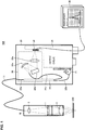
- the confocal measurement device 100 includes a head unit 10 having a confocal optical system, a controller 20 that is optically connected thereto by an optical fiber 11, and a monitor 30 that displays signals that are output from the controller 20.
- the head unit 10 includes a diffraction lens 1 and an objective lens 2 that is closer to the measurement object 200 than the diffraction lens 1.
- the focus distance of the diffraction lens 1 is larger than the difference between the distance from the diffraction lens to the objective lens and the focus distance of the objective lens.
- the diffraction lens 1 is an optical element that causes chromatic aberration along the optical axis direction in the light that is emitted from a light source emitting polychromatic light (for example, a white light source), as explained below.
- the diffraction lens 1 may be made by periodically forming fine protrusions, such as a kinoform shape or a binary shape (step shape), or by forming an amplitude-type zone-plate, in which the optical transmittance changes periodically, on the surface of a lens. It should be noted that the configuration of the diffraction lens 1 is not limited to the above-noted configurations.
- the objective lens 2 is an optical element that focuses the light, into which chromatic aberration has been introduced by the diffraction lens 1, onto the measurement object 200. It should be noted that the following is an explanation for the case that the confocal measurement device 100 uses a white light source as the light source emitting polychromatic light.
- the light emitted from the white light source is guided via the optical fiber 11 to the head unit 10.
- the numerical aperture (NA) of the optical fiber 11 should match the numerical aperture of the diffraction lens 1.
- a collecting lens 3 is provided between the optical fiber 11 and the diffraction lens 1, and an adjustment is made to match the numerical aperture of the optical fiber 11 to the numerical aperture of the diffraction lens 1.
- the optical fiber 11 is a light path from the head unit 10 to the controller 20, and functions also as a pinhole. That is to say, of the light that is condensed with the objective lens 2, only the light that is in focus at the measurement object 200 is in focus at the aperture of the optical fiber 11. For this reason, the optical fiber 11 blocks the light of wavelengths that are not in focus at the measurement object 200, and functions as a pinhole that lets only light focused on the measurement object 200 pass. By using the optical fiber 11 as the light path from the head unit 10 to the controller 20, a separate pinhole becomes unnecessary.
- the confocal measurement device 100 may also have a configuration in which no optical fiber 11 is used for the light path from the head unit 10 to the controller 20, but by using the optical fiber 11 as the light path, it is possible to flexibly move the head unit 10 with respect to the controller. Moreover, if the confocal measurement device 100 has a configuration in which no optical fiber 11 is used for the light path from the head unit 10 to the controller 20, then it is necessary to provide a pinhole, but if the optical fiber 11 is used, then the confocal measurement device 100 does not need to be provided with a separate pinhole.
- the controller 20 includes a white LED (Light Emitting Diode) 21 serving as the white light source, a branched optical fiber 22, a spectrometer 23, an imaging element 24, and a control circuit 25.
- the white LED 21 is used as the white light source, but it is also possible to use another light source, as long as it can emit white light.
- the branched optical fiber 22 includes one optical fiber 22a on the side where it is connected to the optical fiber 11, and two optical fibers 22b and 22c on the opposite side.
- the optical fiber 22b is connected to the white LED 21 and the optical fiber 22c is connected to the spectrometer 23.
- the branched optical fiber 22 can guide light emitted from the white LED 21 to the optical fiber 11 and light returning via the optical fiber 11 from the head unit 10 to the spectrometer 23.
- the spectrometer 23 includes a concave mirror 23a that reflects the light returning from the head unit 10, a diffraction grating 23b on which the light reflected from the concave mirror 23a is incident, and a condensing lens 23c that condenses the light emitted from the diffraction grating 23b.
- the spectrometer 23 may also be of the Czerny-Turner type or of the Littrow type, as long as it can divide light returning from the head unit 10 by wavelength.
- the imaging element 24 may be a line CMOS (Complementary Metal Oxide Semiconductor) or CCD (Charge Coupled Device) that measures the intensity of the light that is emitted from the spectrometer 23.
- CMOS Complementary Metal Oxide Semiconductor
- CCD Charge Coupled Device
- the spectrometer 23 and the imaging element 24 constitute a measurement unit that measures or evaluates, by wavelength, the intensity of light that returns from the head unit 10. It should be noted that as long as it can measure, by wavelength, the intensity of light that returns from the head unit 10, the measurement unit may also be simply constituted by an imaging element 24, such as a CCD.
- the imaging element 24 may be a two-dimensional CMOS or a two-dimensional CCD.
- the control circuit 25 is a circuit that controls the operation of the white LED 21, the imaging element 24 and the like. Moreover, although not shown in the drawings, the control circuit 25 includes an input interface into which a signal for adjusting the operation of the white LED 21, the imaging element 24 and the like is input, and an output interface from which the signal of the imaging element 24 is output.
- the monitor 30 displays the signals that are output by the imaging element 24.
- the monitor 30 may render the spectral waveform of the light returning from the head unit 10, and may display that the displacement of the measurement object is 123.45 micrometers.
- Fig. 2 is a diagrammatic view illustrating the configuration of the confocal optical system of the head unit that is employed in a conventional confocal measurement device.
- the diffraction lens 400 is arranged closer to the measurement object 200 than a collimator lens 300. That is to say, in conventional confocal measurement devices, the light emitted from the end of the optical fiber 11 is turned into parallel light by the collimator lens 300, and this parallel light is condensed by the diffraction lens 400 onto the measurement object 200, causing chromatic aberration along the optical axis direction.
- the conventional confocal measurement device focuses the light with the diffraction lens 400 onto the measurement object 200, so that due to the optical characteristics of the diffraction lens 400, the depth of field depends strongly on the optical wavelength. If the depth of field changes strongly with the optical wavelength, then the amount of light that can be irradiated into the optical fiber 11 (the amount of light that can pass through the pinhole) also depends on the optical wavelength, so that in the conventional confocal measurement device, the precision (resolution) with which displacements of the measurement object can be measured varies greatly with the optical wavelength.
- the precision with which displacements of the measurement object can be measured can be evaluated with the full-width at half-maximum (FWHM) of the spectrum in the spectral waveform obtained with the measurement unit of the confocal measurement device.
- FWHM of the spectrum refers to the difference between the two points of the spectrum where the intensity of the light is 1/2 that of the peak.
- Fig. 3 is a diagram showing an example of a spectral waveform of a displacement of the measurement object measured with a conventional confocal measurement device.
- the horizontal axis denotes the workpiece height, which corresponds to the optical wavelength (the height from the measurement object 200 to the front end of the head 10 is set as zero) (in mm)
- the vertical axis denotes the intensity of the light (normalized value).
- the spectral waveform shows a plurality of peaks in the spectrum, and the FWHM of the spectrum is larger for negative workpiece heights (for shorter wavelengths of light) than for positive workpiece heights (for longer wavelengths of light).
- this FWHM also depends on the diameter of the optical fiber 11 and the depth of focus of the lens 300 on the side of the optical fiber 11. As the radius of the optical fiber 11 becomes smaller or the depth of focus of the lens 300 becomes shorter, the FWHM becomes narrower. However, since the diameter of the optical fiber 11 and the depth of focus of the lens 300 on the side of the optical fiber 11 are fixed within the measurement device, the relative difference in the FWHM due to the height of the workpiece does not change.
- the FWHM A of the spectrum at a workpiece height of about -0.6 mm is about 0.046 mm, but the FWHM B of the spectrum at a workpiece height of about 0.6 mm is about 0.023 mm. That is to say, the spectrum's FWHM A is about twice the spectrum's FWHM B, and as the workpiece height becomes smaller (the optical wavelength becomes shorter), the FWHM of the spectrum becomes larger. It should be noted that the reason why the peaks of the spectrum change with the workpiece height is that the intensity of the light included in the white light source depends on the optical wavelength.
- the FWHM of the spectrum becomes larger as the workpiece height becomes smaller (the optical wavelength becomes shorter), so that it can be seen that the precision with which the displacement of the measurement object 200 is measured becomes poorer as the workpiece height becomes smaller (the optical wavelength becomes shorter).
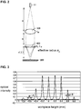
- Fig. 4 is a diagrammatic view showing the configuration of the confocal optical system of the head unit 10 employed in the confocal measurement device 100 according to Embodiment 1 of the present invention.
- the objective lens 2 is arranged closer to the measurement object 200 than the diffraction lens 1. That is to say, in the confocal measurement device 100, the diffraction lens 1 introduces chromatic aberration into the light that is emitted from the end of the optical fiber 11, and the light into which chromatic aberration has been introduced is condensed by the objective lens 2 on the measurement object 200.
- the light is not condensed with the diffraction lens 1 on the measurement object 200, but is condensed with the objective lens 2 on the measurement object 200, so that for the reasons explained below, changes in the depth of field due to the optical wavelength are suppressed, thus suppressing variations in the precision with which displacements of the measurement object 200 are measured.
- Fig. 5 is a diagram showing an example of a spectral waveform of a displacement of the measurement object measured with the confocal measurement device 100 according to Embodiment 1 of the present invention.
- the horizontal axis denotes the workpiece height, which corresponds to the optical wavelength (the height from the measurement object 200 to the front end of the head 10 is set as zero) (in mm), and the vertical axis denotes the intensity of the light (normalized value).
- the spectral waveform shows a plurality of peaks in the spectrum, and the FWHM of the spectrum for negative workpiece heights (for shorter wavelengths of light) is substantially the same as the FWHM of the spectrum for positive workpiece heights (for longer wavelengths of light).
- the FWHM C of the spectrum at a workpiece height of about -0.6 mm is about 0.025 mm
- the FWHM D of the spectrum at a workpiece height of about 0.6 mm is about 0.029 mm. That is to say, the FWHM C in the spectrum is about twice that of the FWHM D in the spectrum.
- the confocal measurement device 100 suppresses variations, due the optical wavelength, in the precision with which a displacement of the measurement object 200 is measured.
- Fig. 6 is a graph showing the change of the FWHM of the spectrum as a function of the workpiece height.
- the broken line “a” shows the FWHM in the spectrum according to the conventional confocal measurement device (the FWHM in the spectrum shown in Fig. 3 )
- the broken line “b” shows the FWHM in the spectrum according to the confocal measurement device 100 (the FWHM in the spectrum shown in Fig. 5 ).
- the broken line "a” the FWHM becomes larger the smaller the workpiece height is (the shorter the optical wavelength)
- the FWHM is substantially constant with respect to workpiece height is (optical wavelength).
- the FWHM of the spectrum shown by the broken line “a” is inclined and changes between about 0.023 mm and about 0.046 mm
- the FWHM of the spectrum shown by the broken line “b” changes between about 0.023 mm and about 0.034 mm, with about 0.030 mm at the center.
- a is the distance from the end of the optical fiber 11 to the diffraction lens 1
- b is the distance from the diffraction lens 1 to the objective lens 2
- c( ⁇ ) is the distance from the objective lens 2 to the point on which the light is focused by the objective lens 2.
- f d0 is the focus distance of the diffraction lens 1 for the wavelength ⁇ 0 of light
- ⁇ a is the effective radius of the diffraction lens 1. It should be noted that the distance a is set to be the same as the focus distance f d0 .
- f o is the focus distance of the objective lens 2
- ⁇ b ( ⁇ ) is the effective radius of the objective lens 2.
- a is the distance from the end of the optical fiber 11 to the collimator lens 300
- b is the distance from the collimator lens 300 to the diffraction lens 400
- c( ⁇ ) is the distance from the diffraction lens 400 to the point on which the light is focused by the diffraction lens 400.
- f d0 is the focus distance of the collimator lens 300. It should be noted that the distance a is set to be the same as the focus distance f d0 . Also, f o is the focus distance of the diffraction lens 400 for the wavelength ⁇ 0 of light, and ⁇ a is the effective radius of the diffraction lens 400.
- the focus distance f d ( ⁇ ) of the diffraction lens 400 is a function of the optical wavelength ⁇ , and if f o is the focus distance for the optical wavelength ⁇ 0 , then, using the formula for the diffraction lens, the focus distance f d ( ⁇ ) can be expressed in general terms by the following Equation 1.
- Equation 2 the numerical aperture NA 1 ( ⁇ ) of the diffraction lens 400 can be expressed by the following Equation 2.
- the relationship between the distance a from the end of the optical fiber 11 to the diffraction lens 1, the distance a g ( ⁇ ) (not shown in the drawings) from the diffraction lens 1 to the point where the light emitted from the optical fiber 11 is focused by the diffraction lens 1, and the focus distance f d ( ⁇ ) of the diffraction lens 1, and the relationship between the distance b from the diffraction lens 1 to the objective lens 2, the distance c( ⁇ ) from the objective lens 2 to the point where the light is focused by the objective lens 2, and the focus distance f o of the objective lens 2 can be expressed by the following Equation 3.
- Equation 3 chromatic aberrations due to the objective lens can be ignored.
- Equation 4 the effective radius ⁇ b ( ⁇ ) of the objective lens 2 can be expressed by the following Equation 4:
- Equation 5 the distance c( ⁇ ) from the objective lens 2 to the point where the light is focused by the objective lens 2 can be expressed by the following Equation 5:
- Equation 6 the numerical aperture NA 2 ( ⁇ ) of the objective lens 2 can be expressed by the following Equation 6.
- Equation 6 can be expressed by the following Equation 7.
- N ⁇ A 2 ⁇ sin ⁇ a 2 ⁇ f d ⁇ 0 ⁇ 1 - b f o ⁇ ⁇ ⁇ 0 + f d ⁇ 0 f o + b f o - 1
- the numerical aperture NA 1 ( ⁇ ) of the diffraction lens 400 which corresponds to the objective lens in the conventional configuration, is compared to the numerical aperture NA 2 ( ⁇ ) of the objective lens 2 of the present invention, while considering the condition given in Equation 8.
- the condition given in Equation 8 states that the focus distance f d0 of the diffraction lens 1 for the optical wavelength ⁇ 0 is larger than the difference between the distance b from the diffraction lens 1 to the objective lens 2 and the focus distance of the objective lens.
- the ratio of change with respect to the optical wavelength ⁇ of the numerical aperture NA 2 ( ⁇ ) of the objective lens 2 (the slope in its function of the optical wavelength ⁇ ) is smaller than that of the numerical aperture NA 1 ( ⁇ ) of the diffraction lens 400.
- Fig. 7 is a graph showing a comparison of the numerical aperture of the diffraction lens 400 and the numerical aperture of the objective lens 2.
- the horizontal axis denotes the optical wavelength and the vertical axis denotes the inverse sine of the numerical aperture.
- the straight line c represents the numerical aperture NA 1 ( ⁇ ) of the diffraction lens 400 and the straight line d represents the NA 2 ( ⁇ ) of the objective lens 2.
- the straight line d has a smaller slope than the straight line c. That is to say, the NA 2 ( ⁇ ) of the objective lens 2 changes less with respect to the optical wavelength ⁇ than the numerical aperture NA 1 ( ⁇ ) of the diffraction lens 400. And since the NA 2 ( ⁇ ) of the objective lens 2 changes less with respect to the optical wavelength ⁇ , the objective lens 2 can suppress changes in the depth of field with respect to the optical wavelength ⁇ .
- the numerical aperture NA 2 ( ⁇ ) of the objective lens 2 becomes a constant value that does not include the variable of the optical wavelength ⁇ . That is to say, in this case, the numerical aperture NA 2 ( ⁇ ) of the objective lens 2 does not change with the optical wavelength ⁇ . Therefore, even when changing the optical wavelength ⁇ in the confocal measurement device 100, the light amount that can be coupled into the optical fiber 11 (the light amount that can pass through the pinhole) is constant, and the precision with which displacements of the measurement object can be measured is constant and does not depend on the wavelength.
- Fig. 8 is a diagrammatic view showing the configuration of the head unit 10 of the confocal measurement device 100 according to Embodiment 1 of the present invention.
- the objective lens 2 is adhered to a spacer 4, and this spacer 4 is removable, so that it is possible to exchange the objective lens 2.
- a ring 5 can be removed from the head unit 10, and the spacer 4 can be moved in optical axis direction to retrieve the spacer 4 from the head unit 10, and by inserting a spacer 4 to which an objective lens 2 with a different focus length is adhered, it is easy to exchange the objective lens 2 in the head unit 10.
- By exchanging the objective lens 2 to an objective lens 2 with a different focus length it is possible to change the distance between the head unit 10 and the measurement object 200 and the range of the workpiece height (WD) that can be measured in the confocal measurement device 100.
- WD workpiece height
- an ordinary optical lens is used for the objective lens 2, but it is also possible to use an achromatic lens, in which a convex lens and a concave lens that are made of two types of glass materials with different refractive indices are placed in close proximity to each other or adhered to each other.
- Achromatic lenses can be designed to remove chromatic aberrations, so that by using an achromatic lens as the objective lens 2, it is possible to further suppress variations, due to the optical wavelength ⁇ , in the precision with which the confocal measurement device 100 measures displacements of the measurement object 200.
- a multimode fiber or a single-mode fiber may be used for the optical fiber 11. If a multimode fiber is used for the optical fiber 11, then the diameter of the fiber is large, so that the loss of optical power when transmitting the light emitted from the white LED 21 can be made small, and a reliable measurement with a high S/N ratio is possible even for a measurement object with lower reflectivity. If a single-mode fiber is used for the optical fiber 11, then the diameter of the fiber is several ⁇ m small, so that functioning as a pinhole, the FWHM of the received optical waveform can be made narrow as described above, and a measurement with high precision is possible. Ordinarily, if an optical fiber is used in a confocal optical system, the loss of optical power becomes large, so that also the S/N ratio often becomes problematic, and it is desirable to use a multimode fiber for the optical fiber 11.
- the head unit 10 is attached to a driving portion such as an electronic component mounting apparatus or the like, and in this case, also the head unit 10 itself moves. Therefore, the optical fiber 11 connected to the head unit 10 bends right along in the movement direction of the head unit 10, so that damage can be prevented by using a bendable fiber.
- the diffraction lens 1 is not limited to a configuration in which a pattern causing chromatic aberration in optical axis direction is formed on a substrate made of a single material, such as glass or plastic, and it may also be constituted by a plurality of materials.
- Fig. 9 is a diagrammatic view of a diffraction lens 1 made of a plurality of materials.
- the diffraction lens 1 shown in Fig. 9 includes a glass substrate 1 a, and a resin layer 1 b with a pattern that causes chromatic aberration in optical axis direction, formed on one side of the glass substrate 1 a.
- the resin layer 1 b can be made by applying a UV-curing resin to the glass substrate 1 a, pressing a die of the desired pattern against the side of the glass substrate 1 a to which the UV-curing resin has been applied, and curing the UV-curing resin by irradiation of UV light.
- a diffraction lens 1 made only of glass is quite high, since it is made by processing hard glass to form a pattern that causes chromatic aberrations in the optical axis direction.
- the resin layer 1 b is processed with a die of the desired pattern to form the pattern that causes chromatic aberrations in the optical axis direction, so that its manufacturing costs are lower.
- a diffraction lens 1 that is made only of resin changes considerably with the ambient temperature, and it has poor temperature characteristics.
- the glass substrate 1 a whose shape changes hardly with the ambient temperature, accounts for most of the configuration, so that its temperature characteristics are good.
- the confocal measurement device 100 As explained above, in the confocal measurement device 100 according to the present invention, changes in the depth of field due to the optical wavelength can be suppressed, and variations, due to the optical wavelength, in the precision with which displacements of the measurement object 200 are measured can be suppressed by arranging the objective lens 2 closer to the measurement object 200 than the diffraction lens 1 and making the focus distance of the diffraction lens 1 larger than the difference between the distance from the diffraction lens 1 to the objective lens 2 and the focus distance of the objective lens 2.
- the coupling of the optical fiber 22b with the head unit 10, the spectrometer 23 and the white LED 21 constituting the confocal measurement device 100 shown in Fig. 1 is replaced by a coupling between the optical fiber and the head unit, the spectrometer and the white LED having a different configuration.
- Fig. 10 is a schematic view showing the configuration of a head unit of a confocal measurement device 100 according to Embodiment 2 of the present invention.
- the head unit 10a shown in Fig. 10 includes a main unit 12 including a diffraction lens 1, and an objective lens unit 13 having an objective lens 2.
- Objective lens units 13 with different objective lenses 2 depending on the object to be measured may be prepared, and these objective lens units 13 can be fitted to the main unit 12, so that they can be easily exchanged.
- the main unit 12 and the objective lens unit 13 can be fitted together by any method, such as screwing them together or coupling them together, as long the main unit 12 and the objective lens unit 13 can be fastened together.
- the main unit 12 is provided with a fiber receptacle 14 for connecting the optical fiber 11.
- the optical fiber 11 is provided with an optical connector 15 that can be fitted to the fiber receptacle 14 at the end that is to be connected to the main unit 12.
- the main unit 12 can be connected detachably to the optical fiber 11.
- the optical fiber 11 is merely replaced, there is also no need to readjust the optical axis of the head unit 10a, and it is possible to resume the measurement immediately after replacing the optical fiber 11.
- an APC (Angled PC) polished fiber is used for the optical fiber 11 in which the face at the end (end face) on the side connected to the main unit 12 is cut obliquely with respect to the optical axis. Therefore, the reflection light from the end face of the optical fiber 11 can be reduced, the offset to the received waveform due to the reflection light can be reduced and a narrowing of the measurement range can be suppressed.
- APC Angled PC
- the emission direction of the light becomes oblique with respect to the optical axis of the optical fiber 11, so that it is necessary to place the central axis of the fiber receptacle 14 obliquely with respect to the central axis of the main unit 12 such that the emission direction of the light is aligned with central axis of the main unit 12.
- the head unit 10a shown in Fig. 10 has a small shape, so that the distance between the diffraction lens 1 and the objective lens 2 is smaller than the focus distance of the objective lens 2. Furthermore, the head unit 10a shown in Fig. 10 does not employ the condensing lens 3 shown in Fig. 8 . For this reason, the head unit 10a shown in Fig. 10 has a poorer light utilization efficiency than the head unit 10 shown in Fig. 8 , but since the number of lenses is reduced, it is also possible to reduce the costs of the lenses and the number of man-hours required to adjust the lenses.
- Fig. 11 is a diagrammatic view showing the configuration of the spectrometer of the confocal measurement device 100 according to Embodiment 2 of the present invention.
- the spectrometer 230 shown in Fig. 11 which is of the Czerny-Turner type, includes a diffraction grating 23b, a condensing lens 23c, and a collimator lens 23d. It should be noted that constituent elements of the spectrometer 230 in Fig. 11 that are the same as those of the spectrometer 23 shown in Fig. 1 have been assigned the same reference numerals.
- the light returning from the head unit 10 via the optical fiber 22c is irradiated into the spectrometer 230.
- the light emitted from the optical fiber 22c is collimated by a collimator lens 23d, and after being reflected by a diffraction grating 23b, it is condensed by a condensing lens 23c and irradiated onto a CCD serving as the imaging element 24.
- a fiber ferrule 22c1 is provided at the end of the optical fiber 22c, and this fiber ferrule 22c1 is fixed to a fiber receptacle 23e.
- the diffraction grating 23b, the condensing lens 23c, the collimator lens 23d, the fiber receptacle 23e and the imaging element 24 are fixed to a spectrometer base 23f such that their positions cannot be easily shifted.
- the spectrometer 230 uses a collimator lens 23d that is a simple lens instead of a reflecting mirror, so that the costs can be reduced.
- Fig. 12 is a diagrammatic view showing the configuration of the coupling unit coupling the white LED and the optical fiber of the confocal measurement device 100 according to Embodiment 2 of the present invention.
- the coupling unit coupling the white LED 21 and the optical fiber 22b shown in Fig. 12 includes a retaining case 210 and a fiber holder 211.
- a substrate 21 a on which the white LED 21 is mounted is fixed with screws or the like to the retaining case 210.
- the retaining case 210 is made of metal, such as an aluminum alloy or the like and easily dissipates the heat that is generated when the white LED 21 is on via the substrate 21 a. It should be noted that in order to keep down the amount of heat generated, it is preferable that the white LED 21 blinks in pulses, but to suppress noise, it is preferable that the white LED 21 is continuously on.
- the coupling unit coupling the white LED 21 and the optical fiber 22b is configured by inserting a fiber ferrule 22b1 of the optical fiber 22b into a recess that is provided on the optical axis of the white LED 21 and fixing the optical fiber 22b with the fiber holder 211.
- the fiber ferrule 22b1 of the optical fiber 22b is a metal or ceramic component to protect the tip of the fiber, and the diameter of its tip is about 50 ⁇ m.
- the distance between the white LED 21 and the tip of the fiber ferrule 22b1 should be as short as possible, in order to increase the utilization efficiency of the light. However, considering manufacturing variability, it is necessary to leave a distance between the white LED 21 and the tip of the fiber ferrule 22b1 that corresponds to the dimensional tolerances of the white LED 21, the fiber ferrule 22b1 and the like.
- the white LED 21 that is used in the confocal measurement device 100 according to Embodiment 2.
- an LED of the fluorescent type is used.
- Fluorescent white LEDs have a structure in which a chip of an LED emitting blue light or light of an even shorter wavelength is covered by a fluorescent material, and white light is obtained by obtaining the light emitted from the chip and the excitation light of the fluorescent material due to that light.
- Fig. 13 is a diagram showing the spectrum of the white LED 21 of the fluorescent type.
- the spectrum shown in Fig. 13 contains two components, namely components having a large intensity in the blue range (near the wavelength of 440 nm) and components whose intensity changes smoothly over the wavelengths from 500 nm to 700 nm.
- the components of the spectrum that have a large intensity are the components of light that is emitted from the chip and the components of the spectrum whose intensity changes smoothly are the components of the excitation light of the fluorescent substance.
- a light source having an intensity distribution that is nearly uniform over the wavelength axis is ideal, so that it is preferable to use the components of the spectrum whose intensity changes smoothly.
- the wavelengths at which an intensity of at least half that of the peak (at a wavelength of 560 nm) of the components of the spectrum whose intensity changes smoothly is attained are taken as the measurement range (the wavelengths of 520 - 650 nm) of the confocal measurement device 100.
- the emission intensity of the white LED 21 is adjusted in order to obtain stable measurement results with the confocal measurement device 100 according to Embodiment 2 of the present invention. That is to say, if the emission intensity of the white LED 21 of the confocal measurement device 100 is too large, then the waveform received by the imaging element 24 saturates, so that the correct peak cannot be obtained, and conversely, if the emission intensity of the white LED 21 is too small, then the waveform received by the imaging element 24 is buried in noise, so that the correct peak cannot be obtained.
- the emission intensity in the spectrum of the white LED 21 changes with the wavelength and is not constant. For this reason, it is necessary to adjust the intensity of the light emitted by the white LED 21 in order to obtain a stable measurement result.
- Fig. 14 is a drawing showing the relationship between the waveform received by the imaging element 24 and several thresholds.
- the emission intensity of the white LED 21 is adjusted such that the peak of the waveform received by the imaging element 24 lies between a first threshold and a second threshold.
- Fig. 15 is a flowchart illustrating the operation of adjusting the emission intensity of the white LED 21.
- the imaging element 24 takes in the received waveform as shown in Fig. 14 (Step S151).
- the control circuit 25 shown in Fig. 1 judges whether the received waveform obtained with the imaging element 24 contains a peak (Step S152). If the control circuit 25 judges that no peak is contained in the received waveform obtained with the imaging element 24 (Step S152: NO), then the ON current is increased or the emission pulse width is widened, increasing the emission intensity of the white LED 21 (Step S153).
- Step S152 judges whether a peak is contained in the received waveform obtained with the imaging element 24 (Step S152: YES), then it judges whether the peak of the received waveform is at least as large as the first threshold value as shown in Fig. 14 (Step S154). If the control circuit 25 judges that the peak of the received waveform is not at least as large as the first threshold value (that is, smaller than the first threshold value) (Step S154: NO), then the procedure advances to Step S153, and the ON current is increased or the emission pulse width is widened, increasing the emission intensity of the white LED 21.
- Step S154 judges whether the peak of the received waveform is at least as large as the first threshold value (Step S154: YES), then it judges whether the peak of the received waveform is smaller than the second threshold value as shown in Fig. 14 (Step S155). If the control circuit 25 judges that the peak of the received waveform is not smaller than the second threshold value (at least the second threshold value) (Step S155: NO), then the ON current is reduced or the emission pulse width is narrowed, reducing the emission intensity of the white LED 21 (Step S156).
- Step S155: YES If the control circuit 25 judges that the peak of the received waveform is smaller than the second threshold value (Step S155: YES), then the processing is ended.
- a stable measurement result can be obtained with the confocal measurement device 100 according to Embodiment 2 of the present invention, even if the peak of the received waveform changes with the wavelength of the white LED 21 or the peak of the received waveform changes with the reflectivity of the measurement object.
Landscapes
- Physics & Mathematics (AREA)
- General Physics & Mathematics (AREA)
- Chemical & Material Sciences (AREA)
- Analytical Chemistry (AREA)
- Optics & Photonics (AREA)
- Length Measuring Devices By Optical Means (AREA)
- Measurement Of Optical Distance (AREA)
Abstract
Description
- The present invention relates to a confocal measurement device for contactlessly measuring the displacement of a measurement object, which measures the displacement of the measurement object using a confocal optical system.
- As a measurement device for contactlessly measuring the displacement of a measurement object,
Patent Document 1 discloses a confocal measurement device that measures the displacement of a measurement object using a confocal optical system. The confocal measurement device disclosed inPatent Document 1 includes a chromatic aberration lens that introduces chromatic aberration along the optical axis into the light emitted from a light source emitting polychromatic light (such as a white light source). The confocal measurement device disclosed inPatent Document 1 changes the wavelength of light that is passed through a pinhole by varying the wavelength of the light from the chromatic aberration lens that is in focus in accordance with the displacement of the measurement object, and measures the displacement of the measurement object by measuring the wavelength of the light that has passed through the pinhole. - The confocal measurement device disclosed in
Patent Document 2 uses a diffraction lens instead of a chromatic aberration lens to introduce chromatic aberration along the optical axis into the light emitted from a light source. The confocal measurement device disclosed inPatent Document 2 uses an optical fiber for the light path from the light source to a collimator lens and for the light path from the collimator lens to a spectrometer. -
- [Patent Document 1]
US Patent 4,585,349 - [Patent Document 2]
US Patent 5,785,651 - However, the confocal measurement devices disclosed in
Patent Documents Patent Documents - In view of these circumstances, it is an object of the present invention to provide a confocal measurement apparatus for measuring the displacement of a measurement object using a confocal optical system, while suppressing variations, due to the optical wavelength, in the precision with which displacements of the measurement object are measured.
- A confocal measurement device in accordance with the present invention measures a displacement of a measurement object using a confocal optical system. The confocal measurement device includes a light source that emits polychromatic light; a chromatic aberration lens that introduces chromatic aberration in an optical axis direction into the light emitted by the light source; an objective lens that is arranged closer to the measurement object than the chromatic aberration lens, and that condenses the light into which chromatic aberration has been introduced by the chromatic aberration lens onto the measurement object; a pinhole that lets the light condensed by the objective lens that is in focus on the measurement object pass; and a measurement unit that evaluates the light passed by the pinhole for a plurality of wavelengths; wherein a focus distance of the chromatic aberration lens is larger than a difference between a distance from the chromatic aberration lens to the objective lens and a focus distance of the objective lens.
The chromatic aberration lens is a lens that introduces chromatic aberration into light passing through it, and in particular sufficient chromatic aberration that it can be used to measure the distance of an object with a confocal measurement device with the above configuration. The chromatic aberration lens may be a diffraction lens, for example.
The measurement unit may, for example, measure an intensity of the light passed by the pinhole for a plurality of wavelengths. Furthermore, it may determine the wavelength where the intensity of the light passing the pinhole is the greatest. The measurement unit may furthermore output a signal that corresponds to the result of the evaluation, or a signal that represents the displacement of the measurement object. - In the confocal measurement device according to the present invention, it is preferable that the distance from the chromatic aberration lens to the objective lens is substantially the same as the focus distance of the objective lens.
- In the confocal measurement device according to the present invention, it is preferable that the objective lens is exchangeable. Moreover, it is preferable that the confocal measurement device according to the present invention further includes an optical fiber provided in a light path from the chromatic aberration lens to the measurement unit, and that the optical fiber functions as a pinhole.
- Moreover, in the confocal measurement device according to the present invention, it is preferable that the chromatic aberration lens includes a glass substrate and a resin layer formed on at least one side of the glass substrate, the resin layer having a pattern that introduces chromatic aberration in the optical axis direction.
- With the above-described configuration, in the confocal measurement device according to the present invention, changes in the depth of field due to the optical wavelength can be suppressed, and variations, due to the optical wavelength, in the precision with which displacements of the measurement object are measured can be suppressed by arranging the objective lens closer to the measurement object than the chromatic aberration lens and making the focus distance of the chromatic aberration lens larger than the difference between the distance from the chromatic aberration lens to the objective lens and the focus distance of the objective lens.
-
-
Fig. 1 is a diagrammatic view showing the configuration of a confocal measurement device according toEmbodiment 1 of the present invention. -
Fig. 2 is a diagrammatic view illustrating the configuration of the confocal optical system of the head unit that is employed in a conventional confocal measurement device. -
Fig. 3 is a diagram showing an example of a spectral waveform of a displacement of the measurement object measured with a conventional confocal measurement device. -
Fig. 4 is a diagrammatic view showing the configuration of the confocal optical system of the head unit employed in the confocal measurement device according toEmbodiment 1 of the present invention. -
Fig. 5 is a diagram showing an example of a spectral waveform of a displacement of the measurement object measured with the confocal measurement device according toEmbodiment 1 of the present invention. -
Fig. 6 is a graph showing the change of the FWHM of the spectrum as a function of the workpiece height. -
Fig. 7 is a graph showing a comparison of the numerical aperture of the diffraction lens and the numerical aperture of the objective lens. -
Fig. 8 is a diagrammatic view showing the configuration of the head unit of the confocal measurement device according toEmbodiment 1 of the present invention. -
Fig. 9 is a diagrammatic view of a diffraction lens made of a plurality of materials. -
Fig. 10 is a schematic view showing the configuration of a head unit of a confocal measurement device according toEmbodiment 2 of the present invention. -
Fig. 11 is a diagrammatic view showing the configuration of the spectrometer of the confocal measurement device according toEmbodiment 2 of the present invention. -
Fig. 12 is a diagrammatic view showing the configuration of the coupling unit coupling the white LED and the optical fiber of the confocal measurement device according toEmbodiment 2 of the present invention. -
Fig. 13 is a diagram showing the spectrum of the white LED of the fluorescent type. -
Fig. 14 is a drawing showing the relationship between the waveform received by the imaging element and several thresholds. -
Fig. 15 is a flowchart illustrating the operation of adjusting the emission intensity of the white LED. - Referring to the accompanying drawings, the following is a detailed explanation of embodiments of the invention.
-
Fig. 1 is a diagrammatic view showing the configuration of a confocal measurement device according toEmbodiment 1 of the present invention. Theconfocal measurement device 100 shown inFig. 1 is a measurement device for measuring the displacement of ameasurement object 200 using a confocal optical system. Themeasurement object 200 that is measured with theconfocal measurement device 100 may be the cell gap of a liquid display panel, for example. - The
confocal measurement device 100 includes ahead unit 10 having a confocal optical system, acontroller 20 that is optically connected thereto by anoptical fiber 11, and amonitor 30 that displays signals that are output from thecontroller 20. - The
head unit 10 includes adiffraction lens 1 and anobjective lens 2 that is closer to themeasurement object 200 than thediffraction lens 1. The focus distance of thediffraction lens 1 is larger than the difference between the distance from the diffraction lens to the objective lens and the focus distance of the objective lens. - Here, the
diffraction lens 1 is an optical element that causes chromatic aberration along the optical axis direction in the light that is emitted from a light source emitting polychromatic light (for example, a white light source), as explained below. Thediffraction lens 1 may be made by periodically forming fine protrusions, such as a kinoform shape or a binary shape (step shape), or by forming an amplitude-type zone-plate, in which the optical transmittance changes periodically, on the surface of a lens. It should be noted that the configuration of thediffraction lens 1 is not limited to the above-noted configurations. - The
objective lens 2 is an optical element that focuses the light, into which chromatic aberration has been introduced by thediffraction lens 1, onto themeasurement object 200. It should be noted that the following is an explanation for the case that theconfocal measurement device 100 uses a white light source as the light source emitting polychromatic light. - The light emitted from the white light source is guided via the
optical fiber 11 to thehead unit 10. To efficiently use the light emitted from theoptical fiber 11 with thediffraction lens 1, the numerical aperture (NA) of theoptical fiber 11 should match the numerical aperture of thediffraction lens 1. For this reason, acollecting lens 3 is provided between theoptical fiber 11 and thediffraction lens 1, and an adjustment is made to match the numerical aperture of theoptical fiber 11 to the numerical aperture of thediffraction lens 1. - The
optical fiber 11 is a light path from thehead unit 10 to thecontroller 20, and functions also as a pinhole. That is to say, of the light that is condensed with theobjective lens 2, only the light that is in focus at themeasurement object 200 is in focus at the aperture of theoptical fiber 11. For this reason, theoptical fiber 11 blocks the light of wavelengths that are not in focus at themeasurement object 200, and functions as a pinhole that lets only light focused on themeasurement object 200 pass. By using theoptical fiber 11 as the light path from thehead unit 10 to thecontroller 20, a separate pinhole becomes unnecessary. - The
confocal measurement device 100 may also have a configuration in which nooptical fiber 11 is used for the light path from thehead unit 10 to thecontroller 20, but by using theoptical fiber 11 as the light path, it is possible to flexibly move thehead unit 10 with respect to the controller. Moreover, if theconfocal measurement device 100 has a configuration in which nooptical fiber 11 is used for the light path from thehead unit 10 to thecontroller 20, then it is necessary to provide a pinhole, but if theoptical fiber 11 is used, then theconfocal measurement device 100 does not need to be provided with a separate pinhole. - The
controller 20 includes a white LED (Light Emitting Diode) 21 serving as the white light source, a branchedoptical fiber 22, aspectrometer 23, animaging element 24, and acontrol circuit 25. Thewhite LED 21 is used as the white light source, but it is also possible to use another light source, as long as it can emit white light. - The branched
optical fiber 22 includes oneoptical fiber 22a on the side where it is connected to theoptical fiber 11, and twooptical fibers optical fiber 22b is connected to thewhite LED 21 and theoptical fiber 22c is connected to thespectrometer 23. For this reason, the branchedoptical fiber 22 can guide light emitted from thewhite LED 21 to theoptical fiber 11 and light returning via theoptical fiber 11 from thehead unit 10 to thespectrometer 23. - The
spectrometer 23 includes aconcave mirror 23a that reflects the light returning from thehead unit 10, adiffraction grating 23b on which the light reflected from theconcave mirror 23a is incident, and a condensinglens 23c that condenses the light emitted from thediffraction grating 23b. Thespectrometer 23 may also be of the Czerny-Turner type or of the Littrow type, as long as it can divide light returning from thehead unit 10 by wavelength. - The
imaging element 24 may be a line CMOS (Complementary Metal Oxide Semiconductor) or CCD (Charge Coupled Device) that measures the intensity of the light that is emitted from thespectrometer 23. Here, in thisconfocal measurement device 100, thespectrometer 23 and theimaging element 24 constitute a measurement unit that measures or evaluates, by wavelength, the intensity of light that returns from thehead unit 10. It should be noted that as long as it can measure, by wavelength, the intensity of light that returns from thehead unit 10, the measurement unit may also be simply constituted by animaging element 24, such as a CCD. Moreover, theimaging element 24 may be a two-dimensional CMOS or a two-dimensional CCD. - The
control circuit 25 is a circuit that controls the operation of thewhite LED 21, theimaging element 24 and the like. Moreover, although not shown in the drawings, thecontrol circuit 25 includes an input interface into which a signal for adjusting the operation of thewhite LED 21, theimaging element 24 and the like is input, and an output interface from which the signal of theimaging element 24 is output. - The
monitor 30 displays the signals that are output by theimaging element 24. For example, themonitor 30 may render the spectral waveform of the light returning from thehead unit 10, and may display that the displacement of the measurement object is 123.45 micrometers. - Next, it is explained how with the confocal optical system of the
head unit 10, variations, due to the wavelength, in the precision with which the displacement of themeasurement object 200 is measured by theconfocal measurement device 100 are suppressed by arranging theobjective lens 2 closer to themeasurement object 200 than thediffraction lens 1, and making the focus distance of thediffraction lens 1 larger than the difference between the distance from thediffraction lens 1 to theobjective lens 2 and the focus distance of theobjective lens 2. - First,
Fig. 2 is a diagrammatic view illustrating the configuration of the confocal optical system of the head unit that is employed in a conventional confocal measurement device. In the configuration of the confocal optical system shown inFig. 2 , thediffraction lens 400 is arranged closer to themeasurement object 200 than acollimator lens 300. That is to say, in conventional confocal measurement devices, the light emitted from the end of theoptical fiber 11 is turned into parallel light by thecollimator lens 300, and this parallel light is condensed by thediffraction lens 400 onto themeasurement object 200, causing chromatic aberration along the optical axis direction. - The conventional confocal measurement device focuses the light with the
diffraction lens 400 onto themeasurement object 200, so that due to the optical characteristics of thediffraction lens 400, the depth of field depends strongly on the optical wavelength. If the depth of field changes strongly with the optical wavelength, then the amount of light that can be irradiated into the optical fiber 11 (the amount of light that can pass through the pinhole) also depends on the optical wavelength, so that in the conventional confocal measurement device, the precision (resolution) with which displacements of the measurement object can be measured varies greatly with the optical wavelength. - The precision with which displacements of the measurement object can be measured can be evaluated with the full-width at half-maximum (FWHM) of the spectrum in the spectral waveform obtained with the measurement unit of the confocal measurement device. Here, the FWHM of the spectrum refers to the difference between the two points of the spectrum where the intensity of the light is 1/2 that of the peak.
-
Fig. 3 is a diagram showing an example of a spectral waveform of a displacement of the measurement object measured with a conventional confocal measurement device. In the spectral waveform shown inFig. 3 , the horizontal axis denotes the workpiece height, which corresponds to the optical wavelength (the height from themeasurement object 200 to the front end of thehead 10 is set as zero) (in mm), and the vertical axis denotes the intensity of the light (normalized value). The spectral waveform shows a plurality of peaks in the spectrum, and the FWHM of the spectrum is larger for negative workpiece heights (for shorter wavelengths of light) than for positive workpiece heights (for longer wavelengths of light). It should be noted that this FWHM also depends on the diameter of theoptical fiber 11 and the depth of focus of thelens 300 on the side of theoptical fiber 11. As the radius of theoptical fiber 11 becomes smaller or the depth of focus of thelens 300 becomes shorter, the FWHM becomes narrower. However, since the diameter of theoptical fiber 11 and the depth of focus of thelens 300 on the side of theoptical fiber 11 are fixed within the measurement device, the relative difference in the FWHM due to the height of the workpiece does not change. - More specifically, the FWHM A of the spectrum at a workpiece height of about -0.6 mm is about 0.046 mm, but the FWHM B of the spectrum at a workpiece height of about 0.6 mm is about 0.023 mm. That is to say, the spectrum's FWHM A is about twice the spectrum's FWHM B, and as the workpiece height becomes smaller (the optical wavelength becomes shorter), the FWHM of the spectrum becomes larger. It should be noted that the reason why the peaks of the spectrum change with the workpiece height is that the intensity of the light included in the white light source depends on the optical wavelength.
- In the conventional confocal measurement device, the FWHM of the spectrum becomes larger as the workpiece height becomes smaller (the optical wavelength becomes shorter), so that it can be seen that the precision with which the displacement of the
measurement object 200 is measured becomes poorer as the workpiece height becomes smaller (the optical wavelength becomes shorter). -
Fig. 4 is a diagrammatic view showing the configuration of the confocal optical system of thehead unit 10 employed in theconfocal measurement device 100 according toEmbodiment 1 of the present invention. In the configuration of the confocal optical system shown inFig. 4 , theobjective lens 2 is arranged closer to themeasurement object 200 than thediffraction lens 1. That is to say, in theconfocal measurement device 100, thediffraction lens 1 introduces chromatic aberration into the light that is emitted from the end of theoptical fiber 11, and the light into which chromatic aberration has been introduced is condensed by theobjective lens 2 on themeasurement object 200. - In the
confocal measurement device 100, the light is not condensed with thediffraction lens 1 on themeasurement object 200, but is condensed with theobjective lens 2 on themeasurement object 200, so that for the reasons explained below, changes in the depth of field due to the optical wavelength are suppressed, thus suppressing variations in the precision with which displacements of themeasurement object 200 are measured. -
Fig. 5 is a diagram showing an example of a spectral waveform of a displacement of the measurement object measured with theconfocal measurement device 100 according toEmbodiment 1 of the present invention. In the spectral waveform shown inFig. 5 , the horizontal axis denotes the workpiece height, which corresponds to the optical wavelength (the height from themeasurement object 200 to the front end of thehead 10 is set as zero) (in mm), and the vertical axis denotes the intensity of the light (normalized value). The spectral waveform shows a plurality of peaks in the spectrum, and the FWHM of the spectrum for negative workpiece heights (for shorter wavelengths of light) is substantially the same as the FWHM of the spectrum for positive workpiece heights (for longer wavelengths of light). - More specifically, the FWHM C of the spectrum at a workpiece height of about -0.6 mm is about 0.025 mm, and the FWHM D of the spectrum at a workpiece height of about 0.6 mm is about 0.029 mm. That is to say, the FWHM C in the spectrum is about twice that of the FWHM D in the spectrum.
- Consequently, since the FWHM of the spectrum hardly changes even when the workpiece height (optical wavelength) changes, the
confocal measurement device 100 suppresses variations, due the optical wavelength, in the precision with which a displacement of themeasurement object 200 is measured. -
Fig. 6 is a graph showing the change of the FWHM of the spectrum as a function of the workpiece height. In the graph shown inFig. 6 , the broken line "a" shows the FWHM in the spectrum according to the conventional confocal measurement device (the FWHM in the spectrum shown inFig. 3 ), and the broken line "b" shows the FWHM in the spectrum according to the confocal measurement device 100 (the FWHM in the spectrum shown inFig. 5 ). According to the broken line "a", the FWHM becomes larger the smaller the workpiece height is (the shorter the optical wavelength), whereas according to the broken line "b", the FWHM is substantially constant with respect to workpiece height is (optical wavelength). More specifically, the FWHM of the spectrum shown by the broken line "a" is inclined and changes between about 0.023 mm and about 0.046 mm, whereas the FWHM of the spectrum shown by the broken line "b" changes between about 0.023 mm and about 0.034 mm, with about 0.030 mm at the center. - The following is a logical explanation, using equations, of how the
confocal measurement device 100 suppresses changes in the depth of field due to the wavelength, and suppresses variations, due the optical wavelength, in the precision with which a displacement of themeasurement object 200 is measured. - First, in the optical system of the
confocal measurement device 100 shown inFig. 4 , "a" is the distance from the end of theoptical fiber 11 to thediffraction lens 1, "b" is the distance from thediffraction lens 1 to theobjective lens 2, and c(λ) is the distance from theobjective lens 2 to the point on which the light is focused by theobjective lens 2. Moreover, fd0 is the focus distance of thediffraction lens 1 for the wavelength λ0 of light, and Øa is the effective radius of thediffraction lens 1. It should be noted that the distance a is set to be the same as the focus distance fd0. Also, fo is the focus distance of theobjective lens 2, and øb(λ) is the effective radius of theobjective lens 2. - On the other hand, in the optical system of the conventional confocal measurement device, in order to keep the calculation simple, "a" is the distance from the end of the
optical fiber 11 to thecollimator lens 300, "b" is the distance from thecollimator lens 300 to thediffraction lens 400, and c(λ) is the distance from thediffraction lens 400 to the point on which the light is focused by thediffraction lens 400. Moreover, fd0 is the focus distance of thecollimator lens 300. It should be noted that the distance a is set to be the same as the focus distance fd0. Also, fo is the focus distance of thediffraction lens 400 for the wavelength λ0 of light, and øa is the effective radius of thediffraction lens 400. - The focus distance fd(λ) of the
diffraction lens 400 is a function of the optical wavelength λ, and if fo is the focus distance for the optical wavelength λ0, then, using the formula for the diffraction lens, the focus distance fd(λ) can be expressed in general terms by the followingEquation 1. -
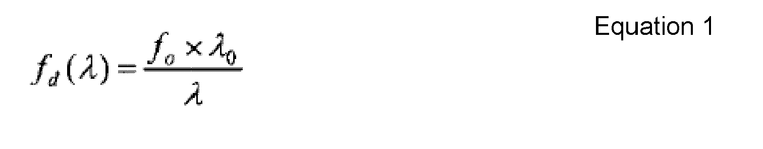
- Furthermore, using the relation stated in Equation (1) the numerical aperture NA1(λ) of the
diffraction lens 400 can be expressed by the followingEquation 2. -

- Next, in the optical system of the
confocal measurement device 100 shown inFig. 4 , using the general lens formula, the relationship between the distance a from the end of theoptical fiber 11 to thediffraction lens 1, the distance ag(λ) (not shown in the drawings) from thediffraction lens 1 to the point where the light emitted from theoptical fiber 11 is focused by thediffraction lens 1, and the focus distance fd(λ) of thediffraction lens 1, and the relationship between the distance b from thediffraction lens 1 to theobjective lens 2, the distance c(λ) from theobjective lens 2 to the point where the light is focused by theobjective lens 2, and the focus distance fo of theobjective lens 2 can be expressed by the followingEquation 3. Here, chromatic aberrations due to the objective lens can be ignored. -

- Furthermore, using the relations of
Equation 3, the effective radius øb(λ) of theobjective lens 2 can be expressed by the following Equation 4: -

- Moreover, using the relation of
Equation 4, the distance c(λ) from theobjective lens 2 to the point where the light is focused by theobjective lens 2 can be expressed by the following Equation 5: -

- Furthermore, using
Equations 3 to 5, the numerical aperture NA2(λ) of theobjective lens 2 can be expressed by the following Equation 6. -

- If the distance a is equal to the focus distance fd0, that is, setting fd0 = a in Equation 6, then Equation 6 can be expressed by the following Equation 7.
-

- Here, the numerical aperture NA1(λ) of the
diffraction lens 400, which corresponds to the objective lens in the conventional configuration, is compared to the numerical aperture NA2(λ) of theobjective lens 2 of the present invention, while considering the condition given in Equation 8. The condition given in Equation 8 states that the focus distance fd0 of thediffraction lens 1 for the optical wavelength λ0 is larger than the difference between the distance b from thediffraction lens 1 to theobjective lens 2 and the focus distance of the objective lens. -
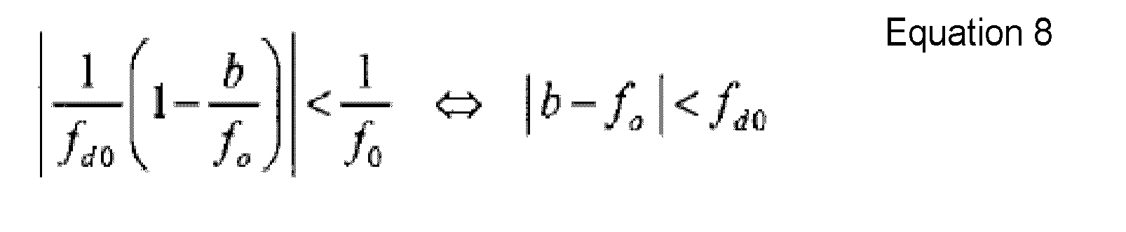
- Considering the condition given in Equation 8, the ratio of change with respect to the optical wavelength λ of the numerical aperture NA2(λ) of the objective lens 2 (the slope in its function of the optical wavelength λ) is smaller than that of the numerical aperture NA1(λ) of the
diffraction lens 400. -
Fig. 7 is a graph showing a comparison of the numerical aperture of thediffraction lens 400 and the numerical aperture of theobjective lens 2. In the graph shown inFig. 7 , the horizontal axis denotes the optical wavelength and the vertical axis denotes the inverse sine of the numerical aperture. The straight line c represents the numerical aperture NA1(λ) of thediffraction lens 400 and the straight line d represents the NA2(λ) of theobjective lens 2. - Given the condition of Equation 8, it can be seen that the straight line d has a smaller slope than the straight line c. That is to say, the NA2(λ) of the
objective lens 2 changes less with respect to the optical wavelength λ than the numerical aperture NA1(λ) of thediffraction lens 400. And since the NA2(λ) of theobjective lens 2 changes less with respect to the optical wavelength λ, theobjective lens 2 can suppress changes in the depth of field with respect to the optical wavelength λ. - Note that if the distance b is equal to the focus distance fd0 (b = fd0), then the numerical aperture NA2(λ) of the
objective lens 2 becomes a constant value that does not include the variable of the optical wavelength λ. That is to say, in this case, the numerical aperture NA2(λ) of theobjective lens 2 does not change with the optical wavelength λ. Therefore, even when changing the optical wavelength λ in theconfocal measurement device 100, the light amount that can be coupled into the optical fiber 11 (the light amount that can pass through the pinhole) is constant, and the precision with which displacements of the measurement object can be measured is constant and does not depend on the wavelength. - The following is a more detailed explanation of the
head unit 10.Fig. 8 is a diagrammatic view showing the configuration of thehead unit 10 of theconfocal measurement device 100 according toEmbodiment 1 of the present invention. In thehead unit 10 shown inFig. 8 , theobjective lens 2 is adhered to aspacer 4, and thisspacer 4 is removable, so that it is possible to exchange theobjective lens 2. More specifically, a ring 5 can be removed from thehead unit 10, and thespacer 4 can be moved in optical axis direction to retrieve thespacer 4 from thehead unit 10, and by inserting aspacer 4 to which anobjective lens 2 with a different focus length is adhered, it is easy to exchange theobjective lens 2 in thehead unit 10. By exchanging theobjective lens 2 to anobjective lens 2 with a different focus length, it is possible to change the distance between thehead unit 10 and themeasurement object 200 and the range of the workpiece height (WD) that can be measured in theconfocal measurement device 100. - Here, an ordinary optical lens is used for the
objective lens 2, but it is also possible to use an achromatic lens, in which a convex lens and a concave lens that are made of two types of glass materials with different refractive indices are placed in close proximity to each other or adhered to each other. Achromatic lenses can be designed to remove chromatic aberrations, so that by using an achromatic lens as theobjective lens 2, it is possible to further suppress variations, due to the optical wavelength λ, in the precision with which theconfocal measurement device 100 measures displacements of themeasurement object 200. - Moreover, a multimode fiber or a single-mode fiber may be used for the
optical fiber 11. If a multimode fiber is used for theoptical fiber 11, then the diameter of the fiber is large, so that the loss of optical power when transmitting the light emitted from thewhite LED 21 can be made small, and a reliable measurement with a high S/N ratio is possible even for a measurement object with lower reflectivity. If a single-mode fiber is used for theoptical fiber 11, then the diameter of the fiber is several µm small, so that functioning as a pinhole, the FWHM of the received optical waveform can be made narrow as described above, and a measurement with high precision is possible. Ordinarily, if an optical fiber is used in a confocal optical system, the loss of optical power becomes large, so that also the S/N ratio often becomes problematic, and it is desirable to use a multimode fiber for theoptical fiber 11. - Moreover, it is desirable to use a bendable fiber for the
optical fiber 11. Often, thehead unit 10 is attached to a driving portion such as an electronic component mounting apparatus or the like, and in this case, also thehead unit 10 itself moves. Therefore, theoptical fiber 11 connected to thehead unit 10 bends right along in the movement direction of thehead unit 10, so that damage can be prevented by using a bendable fiber. - Furthermore, the
diffraction lens 1 is not limited to a configuration in which a pattern causing chromatic aberration in optical axis direction is formed on a substrate made of a single material, such as glass or plastic, and it may also be constituted by a plurality of materials.Fig. 9 is a diagrammatic view of adiffraction lens 1 made of a plurality of materials. Thediffraction lens 1 shown inFig. 9 includes aglass substrate 1 a, and aresin layer 1 b with a pattern that causes chromatic aberration in optical axis direction, formed on one side of theglass substrate 1 a. - The
resin layer 1 b can be made by applying a UV-curing resin to theglass substrate 1 a, pressing a die of the desired pattern against the side of theglass substrate 1 a to which the UV-curing resin has been applied, and curing the UV-curing resin by irradiation of UV light. - The manufacturing costs of a
diffraction lens 1 made only of glass are quite high, since it is made by processing hard glass to form a pattern that causes chromatic aberrations in the optical axis direction. However, in adiffraction lens 1 made of aglass substrate 1 a and aresin layer 1 b, theresin layer 1 b is processed with a die of the desired pattern to form the pattern that causes chromatic aberrations in the optical axis direction, so that its manufacturing costs are lower. - Moreover, the shape of a
diffraction lens 1 that is made only of resin changes considerably with the ambient temperature, and it has poor temperature characteristics. However, in thediffraction lens 1 made of aglass substrate 1 a and aresin layer 1 b, theglass substrate 1 a, whose shape changes hardly with the ambient temperature, accounts for most of the configuration, so that its temperature characteristics are good. - It should be noted that in the
diffraction lens 1 shown inFig. 9 , there is no limitation to forming theresin layer 1 b on one side of theglass substrate 1a, and it is also possible to form theresin layer 1 b on both sides of theglass substrate 1 a. - As explained above, in the
confocal measurement device 100 according to the present invention, changes in the depth of field due to the optical wavelength can be suppressed, and variations, due to the optical wavelength, in the precision with which displacements of themeasurement object 200 are measured can be suppressed by arranging theobjective lens 2 closer to themeasurement object 200 than thediffraction lens 1 and making the focus distance of thediffraction lens 1 larger than the difference between the distance from thediffraction lens 1 to theobjective lens 2 and the focus distance of theobjective lens 2. - In the following explanations, the coupling of the
optical fiber 22b with thehead unit 10, thespectrometer 23 and thewhite LED 21 constituting theconfocal measurement device 100 shown inFig. 1 is replaced by a coupling between the optical fiber and the head unit, the spectrometer and the white LED having a different configuration. -
Fig. 10 is a schematic view showing the configuration of a head unit of aconfocal measurement device 100 according toEmbodiment 2 of the present invention. Thehead unit 10a shown inFig. 10 includes amain unit 12 including adiffraction lens 1, and anobjective lens unit 13 having anobjective lens 2.Objective lens units 13 with differentobjective lenses 2 depending on the object to be measured may be prepared, and theseobjective lens units 13 can be fitted to themain unit 12, so that they can be easily exchanged. Themain unit 12 and theobjective lens unit 13 can be fitted together by any method, such as screwing them together or coupling them together, as long themain unit 12 and theobjective lens unit 13 can be fastened together. - The
main unit 12 is provided with afiber receptacle 14 for connecting theoptical fiber 11. It should be noted that theoptical fiber 11 is provided with an optical connector 15 that can be fitted to thefiber receptacle 14 at the end that is to be connected to themain unit 12. By fitting thefiber receptacle 14 to the optical connector 15 together, themain unit 12 can be connected detachably to theoptical fiber 11. And by making themain unit 12 and theoptical fiber 11 detachable from each other, it is sufficient to exchange theoptical fiber 11 without exchanging theentire head unit 10a if theoptical fiber 11 is damaged at the location where theconfocal measurement device 100 is set up, so that the running costs of theconfocal measurement device 100 can be decreased. Moreover, since theoptical fiber 11 is merely replaced, there is also no need to readjust the optical axis of thehead unit 10a, and it is possible to resume the measurement immediately after replacing theoptical fiber 11. - For the
optical fiber 11, an APC (Angled PC) polished fiber is used in which the face at the end (end face) on the side connected to themain unit 12 is cut obliquely with respect to the optical axis. Therefore, the reflection light from the end face of theoptical fiber 11 can be reduced, the offset to the received waveform due to the reflection light can be reduced and a narrowing of the measurement range can be suppressed. It should be noted that if an APC polishedoptical fiber 11 is used, the emission direction of the light becomes oblique with respect to the optical axis of theoptical fiber 11, so that it is necessary to place the central axis of thefiber receptacle 14 obliquely with respect to the central axis of themain unit 12 such that the emission direction of the light is aligned with central axis of themain unit 12. - Moreover, the
head unit 10a shown inFig. 10 has a small shape, so that the distance between thediffraction lens 1 and theobjective lens 2 is smaller than the focus distance of theobjective lens 2. Furthermore, thehead unit 10a shown inFig. 10 does not employ the condensinglens 3 shown inFig. 8 . For this reason, thehead unit 10a shown inFig. 10 has a poorer light utilization efficiency than thehead unit 10 shown inFig. 8 , but since the number of lenses is reduced, it is also possible to reduce the costs of the lenses and the number of man-hours required to adjust the lenses. -
Fig. 11 is a diagrammatic view showing the configuration of the spectrometer of theconfocal measurement device 100 according toEmbodiment 2 of the present invention. Thespectrometer 230 shown inFig. 11 , which is of the Czerny-Turner type, includes adiffraction grating 23b, a condensinglens 23c, and acollimator lens 23d. It should be noted that constituent elements of thespectrometer 230 inFig. 11 that are the same as those of thespectrometer 23 shown inFig. 1 have been assigned the same reference numerals. - The light returning from the
head unit 10 via theoptical fiber 22c is irradiated into thespectrometer 230. The light emitted from theoptical fiber 22c is collimated by acollimator lens 23d, and after being reflected by adiffraction grating 23b, it is condensed by a condensinglens 23c and irradiated onto a CCD serving as theimaging element 24. - A fiber ferrule 22c1 is provided at the end of the
optical fiber 22c, and this fiber ferrule 22c1 is fixed to afiber receptacle 23e. Thediffraction grating 23b, the condensinglens 23c, thecollimator lens 23d, thefiber receptacle 23e and theimaging element 24 are fixed to aspectrometer base 23f such that their positions cannot be easily shifted. - In order to collimate the light that is incident from the
optical fiber 22c, thespectrometer 230 uses acollimator lens 23d that is a simple lens instead of a reflecting mirror, so that the costs can be reduced. -
Fig. 12 is a diagrammatic view showing the configuration of the coupling unit coupling the white LED and the optical fiber of theconfocal measurement device 100 according toEmbodiment 2 of the present invention. The coupling unit coupling thewhite LED 21 and theoptical fiber 22b shown inFig. 12 includes a retainingcase 210 and afiber holder 211. Asubstrate 21 a on which thewhite LED 21 is mounted is fixed with screws or the like to the retainingcase 210. The retainingcase 210 is made of metal, such as an aluminum alloy or the like and easily dissipates the heat that is generated when thewhite LED 21 is on via thesubstrate 21 a. It should be noted that in order to keep down the amount of heat generated, it is preferable that thewhite LED 21 blinks in pulses, but to suppress noise, it is preferable that thewhite LED 21 is continuously on. - In the retaining
case 210, the coupling unit coupling thewhite LED 21 and theoptical fiber 22b is configured by inserting a fiber ferrule 22b1 of theoptical fiber 22b into a recess that is provided on the optical axis of thewhite LED 21 and fixing theoptical fiber 22b with thefiber holder 211. The fiber ferrule 22b1 of theoptical fiber 22b is a metal or ceramic component to protect the tip of the fiber, and the diameter of its tip is about 50 µm. - Note that the distance between the
white LED 21 and the tip of the fiber ferrule 22b1 should be as short as possible, in order to increase the utilization efficiency of the light. However, considering manufacturing variability, it is necessary to leave a distance between thewhite LED 21 and the tip of the fiber ferrule 22b1 that corresponds to the dimensional tolerances of thewhite LED 21, the fiber ferrule 22b1 and the like. - The following is a more detailed explanation of the
white LED 21 that is used in theconfocal measurement device 100 according toEmbodiment 2. For thewhite LED 21, an LED of the fluorescent type is used. Fluorescent white LEDs have a structure in which a chip of an LED emitting blue light or light of an even shorter wavelength is covered by a fluorescent material, and white light is obtained by obtaining the light emitted from the chip and the excitation light of the fluorescent material due to that light. -
Fig. 13 is a diagram showing the spectrum of thewhite LED 21 of the fluorescent type. The spectrum shown inFig. 13 contains two components, namely components having a large intensity in the blue range (near the wavelength of 440 nm) and components whose intensity changes smoothly over the wavelengths from 500 nm to 700 nm. The components of the spectrum that have a large intensity are the components of light that is emitted from the chip and the components of the spectrum whose intensity changes smoothly are the components of the excitation light of the fluorescent substance. - Here, in the
confocal measurement device 100 according toEmbodiment 2 of the present invention, a light source having an intensity distribution that is nearly uniform over the wavelength axis is ideal, so that it is preferable to use the components of the spectrum whose intensity changes smoothly. The wavelengths at which an intensity of at least half that of the peak (at a wavelength of 560 nm) of the components of the spectrum whose intensity changes smoothly is attained are taken as the measurement range (the wavelengths of 520 - 650 nm) of theconfocal measurement device 100. - Next, the emission intensity of the
white LED 21 is adjusted in order to obtain stable measurement results with theconfocal measurement device 100 according toEmbodiment 2 of the present invention. That is to say, if the emission intensity of thewhite LED 21 of theconfocal measurement device 100 is too large, then the waveform received by theimaging element 24 saturates, so that the correct peak cannot be obtained, and conversely, if the emission intensity of thewhite LED 21 is too small, then the waveform received by theimaging element 24 is buried in noise, so that the correct peak cannot be obtained. - Moreover, as noted above, the emission intensity in the spectrum of the
white LED 21 changes with the wavelength and is not constant. For this reason, it is necessary to adjust the intensity of the light emitted by thewhite LED 21 in order to obtain a stable measurement result. -
Fig. 14 is a drawing showing the relationship between the waveform received by theimaging element 24 and several thresholds. In order to obtain a stable measurement result, the emission intensity of thewhite LED 21 is adjusted such that the peak of the waveform received by theimaging element 24 lies between a first threshold and a second threshold. -
Fig. 15 is a flowchart illustrating the operation of adjusting the emission intensity of thewhite LED 21. First, theimaging element 24 takes in the received waveform as shown inFig. 14 (Step S151). Next, thecontrol circuit 25 shown inFig. 1 judges whether the received waveform obtained with theimaging element 24 contains a peak (Step S152). If thecontrol circuit 25 judges that no peak is contained in the received waveform obtained with the imaging element 24 (Step S152: NO), then the ON current is increased or the emission pulse width is widened, increasing the emission intensity of the white LED 21 (Step S153). - If the
control circuit 25 judges that a peak is contained in the received waveform obtained with the imaging element 24 (Step S152: YES), then it judges whether the peak of the received waveform is at least as large as the first threshold value as shown inFig. 14 (Step S154). If thecontrol circuit 25 judges that the peak of the received waveform is not at least as large as the first threshold value (that is, smaller than the first threshold value) (Step S154: NO), then the procedure advances to Step S153, and the ON current is increased or the emission pulse width is widened, increasing the emission intensity of thewhite LED 21. - If the
control circuit 25 judges that the peak of the received waveform is at least as large as the first threshold value (Step S154: YES), then it judges whether the peak of the received waveform is smaller than the second threshold value as shown inFig. 14 (Step S155). If thecontrol circuit 25 judges that the peak of the received waveform is not smaller than the second threshold value (at least the second threshold value) (Step S155: NO), then the ON current is reduced or the emission pulse width is narrowed, reducing the emission intensity of the white LED 21 (Step S156). - If the
control circuit 25 judges that the peak of the received waveform is smaller than the second threshold value (Step S155: YES), then the processing is ended. - As described above, by adjusting the emission intensity of the
white LED 21 as shown by the flowchart inFig. 15 a stable measurement result can be obtained with theconfocal measurement device 100 according toEmbodiment 2 of the present invention, even if the peak of the received waveform changes with the wavelength of thewhite LED 21 or the peak of the received waveform changes with the reflectivity of the measurement object. - Note that the flowchart shown in
Fig. 15 was explained for the case that the emission intensity of thewhite LED 21 is adjusted by adjusting the ON current of thewhite LED 21 or adjusting the emitted pulse width, but it is also possible to adjust the peak of the received waveform such that a stable measurement result is obtained by changing the gain or the imaging time of theimaging element 24. - The embodiments disclosed herein are meant to be in all respects illustrative rather than limiting. The scope of the present invention is not limited by the above explanations, but is as defined in the appended claims, and is intended to cover all equivalents as well as modifications within the scope of the claims.
-
- 1, 400 diffraction lens
- 2 objective lens
- 3, 23c condensing lens
- 4 spacer
- 5 ring
- 10, 10a head unit
- 11, 22a, 22b, 22c optical fiber
- 12 main unit
- 13 objective lens unit
- 14, 23e fiber receptacle
- 15 optical connector
- 20 controller
- 21 white LED
- 22 branched optical fiber
- 22b1, 22c1 fiber ferrule
- 23, 230 spectrometer
- 23a concave mirror
- 23b diffraction grating
- 23d collimator lens
- 23f spectrometer base
- 24 imaging element
- 25 control circuit
- 30 monitor
- 100 confocal measurement device
- 200 measurement object
- 210 holding case
- 211 fiber holder
- 300 collimator lens
Claims (5)
- A confocal measurement device for measuring a displacement of a measurement object using a confocal optical system, the confocal measurement device comprising:a light source that emits polychromatic light;a chromatic aberration lens that introduces chromatic aberration in an optical axis direction into the light emitted by the light source;an objective lens that is arranged closer to the measurement object than the chromatic aberration lens, and that condenses the light into which chromatic aberration has been introduced by the chromatic aberration lens onto the measurement object;a pinhole that lets the light condensed by the objective lens that is in focus on the measurement object pass; anda measurement unit that evaluates the light passed by the pinhole for a plurality of wavelengths;wherein a focus distance of the chromatic aberration lens is larger than a difference between a distance from the chromatic aberration lens to the objective lens and a focus distance of the objective lens.
- The confocal measurement device according to claim 1,
wherein the distance from the chromatic aberration lens to the objective lens is substantially the same as the focus distance of the objective lens. - The confocal measurement device according to claim 1 or 2,
wherein the objective lens is exchangeable. - The confocal measurement device according to any of claims 1 to 3,
further comprising an optical fiber provided in a light path from the chromatic aberration lens to the measurement unit;
wherein the optical fiber functions as a pinhole. - The confocal measurement device according to any of claims 1 to 4,
wherein the chromatic aberration lens includes a glass substrate and a resin layer formed on at least one side of the glass substrate, the resin layer having a pattern that introduces chromatic aberration in the optical axis direction.
Applications Claiming Priority (2)
| Application Number | Priority Date | Filing Date | Title |
|---|---|---|---|
| JP2011055485 | 2011-03-14 | ||
| JP2011130230A JP5790178B2 (en) | 2011-03-14 | 2011-06-10 | Confocal measuring device |
Publications (3)
| Publication Number | Publication Date |
|---|---|
| EP2500685A1 true EP2500685A1 (en) | 2012-09-19 |
| EP2500685B1 EP2500685B1 (en) | 2015-12-09 |
| EP2500685B2 EP2500685B2 (en) | 2019-06-19 |
Family
ID=45655902
Family Applications (1)
| Application Number | Title | Priority Date | Filing Date |
|---|---|---|---|
| EP12155695.5A Active EP2500685B2 (en) | 2011-03-14 | 2012-02-16 | Confocal measurement device |
Country Status (5)
| Country | Link |
|---|---|
| EP (1) | EP2500685B2 (en) |
| JP (1) | JP5790178B2 (en) |
| KR (1) | KR101418145B1 (en) |
| CN (1) | CN102679880B (en) |
| TW (1) | TWI452256B (en) |
Cited By (14)
| Publication number | Priority date | Publication date | Assignee | Title |
|---|---|---|---|---|
| WO2013093459A3 (en) * | 2011-12-21 | 2014-01-09 | Taylor Hobson Limited | Chormatic confocal metrological apparatus |
| DE102013008582A1 (en) | 2013-05-08 | 2014-11-27 | Technische Universität Ilmenau | Method and apparatus for chromatic-confocal multipoint measurement and their use |
| CN105403163A (en) * | 2015-10-15 | 2016-03-16 | 上海思信科学仪器有限公司 | Printing ink thickness detection method |
| WO2016092348A1 (en) | 2014-12-09 | 2016-06-16 | Asentys Sas | Integrated optical device for contactless measurement of altitudes and thicknesses |
| EP2933599A4 (en) * | 2012-12-12 | 2016-08-17 | Omron Tateisi Electronics Co | Method and device for measuring displacement |
| EP3306263A1 (en) | 2016-10-04 | 2018-04-11 | Precitec Optronik GmbH | Chromatically confocal distance sensor |
| US9995624B2 (en) | 2015-12-03 | 2018-06-12 | Omron Corporation | Optical measurement device |
| US20190101646A1 (en) * | 2017-09-29 | 2019-04-04 | Omron Corporation | Optical sensor and abnormality detection method for optical sensor |
| US10267622B2 (en) | 2015-12-25 | 2019-04-23 | Keyence Corporation | Confocal displacement sensor |
| US10634485B2 (en) | 2013-11-29 | 2020-04-28 | Grintech Gmbh | Device for contactless optical distance measurement |
| US10794685B2 (en) | 2017-02-23 | 2020-10-06 | Omron Corporation | Optical measurement system |
| WO2021165064A1 (en) * | 2020-02-18 | 2021-08-26 | Agc Glass Europe | Apparatus for removing at least one portion of at least one coating system presenting a multi-glazed window and associated method |
| EP3767258A4 (en) * | 2018-03-12 | 2021-12-01 | Omron Corporation | Wavelength detection device and confocal measurement device |
| EP3901568A4 (en) * | 2018-12-20 | 2022-08-24 | OMRON Corporation | Confocal sensor |
Families Citing this family (42)
| Publication number | Priority date | Publication date | Assignee | Title |
|---|---|---|---|---|
| JP5966982B2 (en) * | 2013-03-15 | 2016-08-10 | オムロン株式会社 | Confocal measuring device |
| US9068822B2 (en) * | 2013-07-03 | 2015-06-30 | Mitutoyo Corporation | Chromatic range sensor probe detachment sensor |
| JP6333065B2 (en) * | 2013-07-09 | 2018-05-30 | 東京エレクトロン株式会社 | Coating device |
| JP6331428B2 (en) | 2014-01-31 | 2018-05-30 | オムロン株式会社 | Sensor head for optical measuring device |
| JP6331499B2 (en) * | 2014-03-07 | 2018-05-30 | オムロン株式会社 | Optical axis adjustment method for confocal measurement apparatus, confocal measurement system, program, and recording medium recording program |
| JP7010589B2 (en) * | 2014-06-27 | 2022-01-26 | 株式会社キーエンス | Multi-wavelength confocal measuring device |
| JP6928688B2 (en) * | 2015-12-25 | 2021-09-01 | 株式会社キーエンス | Confocal displacement meter |
| JP6615604B2 (en) * | 2015-12-25 | 2019-12-04 | 株式会社キーエンス | Confocal displacement meter |
| JP6722450B2 (en) * | 2015-12-25 | 2020-07-15 | 株式会社キーエンス | Confocal displacement meter |
| KR20180099673A (en) * | 2015-12-25 | 2018-09-05 | 가부시키가이샤 키엔스 | Confocal displacement meter |
| JP6654893B2 (en) * | 2015-12-25 | 2020-02-26 | 株式会社キーエンス | Confocal displacement meter |
| CN105841609B (en) * | 2016-03-22 | 2018-04-24 | 哈尔滨工业大学 | A kind of combination socle beam probe sensing device and method for sensing based on light beam scanning probe |
| CN105841608A (en) * | 2016-03-22 | 2016-08-10 | 哈尔滨工业大学 | Optical fiber emergent light collimation detection-based combined cantilever beam probe sensing device and sensing method thereof |
| JP6493265B2 (en) | 2016-03-24 | 2019-04-03 | オムロン株式会社 | Optical measuring device |
| JP6767790B2 (en) * | 2016-06-30 | 2020-10-14 | 株式会社ディスコ | Measuring device and chromatic aberration optical system |
| DE102016115827A1 (en) * | 2016-08-25 | 2018-03-01 | Nanofocus Ag | Method and device for optical surface measurement with the aid of a chromatic confocal sensor |
| US10317344B2 (en) * | 2016-09-07 | 2019-06-11 | Kla-Tencor Corporation | Speed enhancement of chromatic confocal metrology |
| CN106950560A (en) * | 2017-01-16 | 2017-07-14 | 东莞市三姆森光电科技有限公司 | A kind of multidimensional Spectral Confocal ranging software |
| JP2018124167A (en) | 2017-01-31 | 2018-08-09 | オムロン株式会社 | Inclination measuring device |
| JP6819362B2 (en) | 2017-03-02 | 2021-01-27 | オムロン株式会社 | Confocal measuring device |
| JP6819370B2 (en) | 2017-03-09 | 2021-01-27 | オムロン株式会社 | Confocal measuring device |
| JP6834623B2 (en) | 2017-03-13 | 2021-02-24 | オムロン株式会社 | Optical measuring device and adapter for optical measuring device |
| JP6819376B2 (en) | 2017-03-14 | 2021-01-27 | オムロン株式会社 | Displacement measuring device |
| JP6471772B2 (en) * | 2017-06-09 | 2019-02-20 | オムロン株式会社 | Light source device and distance measuring sensor provided with the same |
| JP6971646B2 (en) * | 2017-06-13 | 2021-11-24 | 株式会社キーエンス | Confocal displacement meter |
| JP6971645B2 (en) * | 2017-06-13 | 2021-11-24 | 株式会社キーエンス | Confocal displacement meter |
| JP7024285B2 (en) | 2017-09-26 | 2022-02-24 | オムロン株式会社 | Displacement measuring device, system, and displacement measuring method |
| JP6919458B2 (en) | 2017-09-26 | 2021-08-18 | オムロン株式会社 | Displacement measuring device, measuring system, and displacement measuring method |
| JP6887617B2 (en) | 2017-10-02 | 2021-06-16 | オムロン株式会社 | The sensor head |
| JP6939360B2 (en) * | 2017-10-02 | 2021-09-22 | オムロン株式会社 | Confocal measuring device |
| JP6880508B2 (en) * | 2017-10-02 | 2021-06-02 | オムロン株式会社 | The sensor head |
| JP7064167B2 (en) * | 2018-01-18 | 2022-05-10 | オムロン株式会社 | Optical measuring device and optical measuring method |
| JP6880513B2 (en) * | 2018-03-13 | 2021-06-02 | オムロン株式会社 | Optical measuring device and optical measuring method |
| JP6969459B2 (en) | 2018-03-15 | 2021-11-24 | オムロン株式会社 | The sensor head |
| JP7062518B2 (en) * | 2018-05-25 | 2022-05-06 | 株式会社キーエンス | Confocal displacement meter |
| JP2020076653A (en) * | 2018-11-08 | 2020-05-21 | オムロン株式会社 | Optical measuring device and optical measuring method |
| CN109671783A (en) * | 2018-12-24 | 2019-04-23 | 烟台艾睿光电科技有限公司 | A kind of design of polychrome wafer-level packaging detector and preparation method |
| JP7445201B2 (en) * | 2019-01-11 | 2024-03-07 | オムロン株式会社 | Optical measurement device and optical measurement method |
| JP7031626B2 (en) | 2019-03-13 | 2022-03-08 | オムロン株式会社 | The sensor head |
| JP6875489B2 (en) * | 2019-11-06 | 2021-05-26 | 株式会社キーエンス | Confocal displacement meter |
| JP2022107367A (en) * | 2021-01-08 | 2022-07-21 | オムロン株式会社 | Displacement sensor |
| WO2023096967A1 (en) * | 2021-11-29 | 2023-06-01 | Applied Materials, Inc. | Chromatic focal shift compensation methods and systems |
Citations (6)
| Publication number | Priority date | Publication date | Assignee | Title |
|---|---|---|---|---|
| US4585349A (en) | 1983-09-12 | 1986-04-29 | Battelle Memorial Institute | Method of and apparatus for determining the position of a device relative to a reference |
| US5785651A (en) | 1995-06-07 | 1998-07-28 | Keravision, Inc. | Distance measuring confocal microscope |
| US6674572B1 (en) * | 1997-03-29 | 2004-01-06 | Carl Zeiss Jena Gmbh | Confocal microscopic device |
| DE102005006724A1 (en) * | 2004-10-20 | 2006-08-10 | Universität Stuttgart | Interferometric method e.g. for recording of separation and form and optical coherence tomography (OCT), involves having multi-wavelength source or tunable source and imaging on receiver by focusing systems |
| US20080151253A1 (en) * | 2005-02-03 | 2008-06-26 | Universitat Stuttgart | Method and Assembly for Confocal, Chromatic, Interferometric and Spectroscopic Scanning of Optical, Multi-Layer Data Memories |
| DE102008020902A1 (en) * | 2008-04-18 | 2009-10-29 | Universität Stuttgart | Chromatic-confocal spectral two beam- interferometry arrangement for e.g. microprofile measurement, has semitransparent mirrors and Fabry-perot- interferometer attached to chromatic-confocal spectral two beam- interferometer in rays path |
Family Cites Families (11)
| Publication number | Priority date | Publication date | Assignee | Title |
|---|---|---|---|---|
| US5526338A (en) * | 1995-03-10 | 1996-06-11 | Yeda Research & Development Co. Ltd. | Method and apparatus for storage and retrieval with multilayer optical disks |
| JP3673049B2 (en) * | 1997-02-04 | 2005-07-20 | オリンパス株式会社 | Confocal microscope |
| JP4304713B2 (en) * | 2000-07-10 | 2009-07-29 | 日立化成工業株式会社 | Manufacturing method of optical waveguide device |
| JP4266732B2 (en) † | 2002-08-30 | 2009-05-20 | キヤノン株式会社 | Multilayer diffractive optical element |
| TW200632278A (en) * | 2004-11-08 | 2006-09-16 | Matsushita Electric Ind Co Ltd | Confocal optical device and spherical aberration correcting method |
| DE102005023351A1 (en) † | 2005-05-17 | 2006-11-30 | Micro-Epsilon Messtechnik Gmbh & Co Kg | Apparatus and method for measuring surfaces |
| JP4670669B2 (en) * | 2006-02-08 | 2011-04-13 | スターライト工業株式会社 | Composite optical component and manufacturing method thereof |
| US8089620B2 (en) * | 2006-12-14 | 2012-01-03 | Panasonic Corporation | Method for measuring optical characteristics of diffraction optical element and apparatus for measuring optical characteristics of diffraction optical element |
| US7626705B2 (en) * | 2007-03-30 | 2009-12-01 | Mitutoyo Corporation | Chromatic sensor lens configuration |
| TWI357973B (en) * | 2008-01-16 | 2012-02-11 | Univ Nat Taipei Technology | Apparatus and method for simulataneous confocal fu |
| TWI426296B (en) * | 2009-06-19 | 2014-02-11 | Ind Tech Res Inst | Method and system for three-dimensional polarization-based confocal microscopy |
-
2011
- 2011-06-10 JP JP2011130230A patent/JP5790178B2/en active Active
-
2012
- 2012-02-01 KR KR1020120010133A patent/KR101418145B1/en active IP Right Grant
- 2012-02-01 CN CN201210025124.6A patent/CN102679880B/en active Active
- 2012-02-16 EP EP12155695.5A patent/EP2500685B2/en active Active
- 2012-02-22 TW TW101105724A patent/TWI452256B/en active
Patent Citations (6)
| Publication number | Priority date | Publication date | Assignee | Title |
|---|---|---|---|---|
| US4585349A (en) | 1983-09-12 | 1986-04-29 | Battelle Memorial Institute | Method of and apparatus for determining the position of a device relative to a reference |
| US5785651A (en) | 1995-06-07 | 1998-07-28 | Keravision, Inc. | Distance measuring confocal microscope |
| US6674572B1 (en) * | 1997-03-29 | 2004-01-06 | Carl Zeiss Jena Gmbh | Confocal microscopic device |
| DE102005006724A1 (en) * | 2004-10-20 | 2006-08-10 | Universität Stuttgart | Interferometric method e.g. for recording of separation and form and optical coherence tomography (OCT), involves having multi-wavelength source or tunable source and imaging on receiver by focusing systems |
| US20080151253A1 (en) * | 2005-02-03 | 2008-06-26 | Universitat Stuttgart | Method and Assembly for Confocal, Chromatic, Interferometric and Spectroscopic Scanning of Optical, Multi-Layer Data Memories |
| DE102008020902A1 (en) * | 2008-04-18 | 2009-10-29 | Universität Stuttgart | Chromatic-confocal spectral two beam- interferometry arrangement for e.g. microprofile measurement, has semitransparent mirrors and Fabry-perot- interferometer attached to chromatic-confocal spectral two beam- interferometer in rays path |
Cited By (19)
| Publication number | Priority date | Publication date | Assignee | Title |
|---|---|---|---|---|
| WO2013093459A3 (en) * | 2011-12-21 | 2014-01-09 | Taylor Hobson Limited | Chormatic confocal metrological apparatus |
| EP2933599A4 (en) * | 2012-12-12 | 2016-08-17 | Omron Tateisi Electronics Co | Method and device for measuring displacement |
| DE102013008582A1 (en) | 2013-05-08 | 2014-11-27 | Technische Universität Ilmenau | Method and apparatus for chromatic-confocal multipoint measurement and their use |
| DE102013008582B4 (en) * | 2013-05-08 | 2015-04-30 | Technische Universität Ilmenau | Method and apparatus for chromatic-confocal multipoint measurement and their use |
| US10634485B2 (en) | 2013-11-29 | 2020-04-28 | Grintech Gmbh | Device for contactless optical distance measurement |
| WO2016092348A1 (en) | 2014-12-09 | 2016-06-16 | Asentys Sas | Integrated optical device for contactless measurement of altitudes and thicknesses |
| CN105403163A (en) * | 2015-10-15 | 2016-03-16 | 上海思信科学仪器有限公司 | Printing ink thickness detection method |
| US9995624B2 (en) | 2015-12-03 | 2018-06-12 | Omron Corporation | Optical measurement device |
| US10267622B2 (en) | 2015-12-25 | 2019-04-23 | Keyence Corporation | Confocal displacement sensor |
| US10591278B2 (en) | 2015-12-25 | 2020-03-17 | Keyence Corporation | Confocal displacement sensor |
| EP3306263A1 (en) | 2016-10-04 | 2018-04-11 | Precitec Optronik GmbH | Chromatically confocal distance sensor |
| US10794685B2 (en) | 2017-02-23 | 2020-10-06 | Omron Corporation | Optical measurement system |
| US10514460B2 (en) * | 2017-09-29 | 2019-12-24 | Omron Corporation | Optical sensor and abnormality detection method for optical sensor |
| US20190101646A1 (en) * | 2017-09-29 | 2019-04-04 | Omron Corporation | Optical sensor and abnormality detection method for optical sensor |
| EP3767258A4 (en) * | 2018-03-12 | 2021-12-01 | Omron Corporation | Wavelength detection device and confocal measurement device |
| US11262238B2 (en) | 2018-03-12 | 2022-03-01 | Omron Corporation | Wavelength detection device and confocal measurement device |
| EP3901568A4 (en) * | 2018-12-20 | 2022-08-24 | OMRON Corporation | Confocal sensor |
| US11965729B2 (en) | 2018-12-20 | 2024-04-23 | Omron Corporation | Confocal sensor |
| WO2021165064A1 (en) * | 2020-02-18 | 2021-08-26 | Agc Glass Europe | Apparatus for removing at least one portion of at least one coating system presenting a multi-glazed window and associated method |
Also Published As
| Publication number | Publication date |
|---|---|
| EP2500685B1 (en) | 2015-12-09 |
| CN102679880A (en) | 2012-09-19 |
| KR101418145B1 (en) | 2014-07-09 |
| EP2500685B2 (en) | 2019-06-19 |
| JP5790178B2 (en) | 2015-10-07 |
| TWI452256B (en) | 2014-09-11 |
| CN102679880B (en) | 2015-01-07 |
| JP2012208102A (en) | 2012-10-25 |
| KR20120104929A (en) | 2012-09-24 |
| TW201237356A (en) | 2012-09-16 |
Similar Documents
| Publication | Publication Date | Title |
|---|---|---|
| EP2500685A1 (en) | Confocal measurement device | |
| KR101534912B1 (en) | Confocal measurement apparatus | |
| US7286225B2 (en) | Optical fiber type spectroscope and spectroscope system equipped therewith | |
| US8203708B2 (en) | Spectrally encoded coherent ant-stokes raman scattering endoscope | |
| CN109084686B (en) | Confocal displacement sensor | |
| CN109084684B (en) | Confocal displacement sensor | |
| WO2014141535A1 (en) | Confocal measurement device | |
| US7791712B2 (en) | Chromatic confocal sensor fiber interface | |
| US8098374B2 (en) | Highly sensitive spectroscopic unit | |
| CN107894208B (en) | Spectrum confocal distance sensor | |
| CN109596045B (en) | Confocal measuring device | |
| CN110500971B (en) | Roughness measuring probe, device with roughness measuring probe and corresponding use | |
| EP2811259B9 (en) | Confocal measurement device | |
| JP2017116508A (en) | Confocal displacement meter | |
| TW201248225A (en) | Optical waveguide, laser light irradiation device, and method for assembling laser light irradiation device | |
| US11965729B2 (en) | Confocal sensor | |
| DE102019102873B4 (en) | Sensor system and method for determining geometric properties of a measurement object and coordinate measuring machine | |
| US8108942B2 (en) | Probe microscope | |
| WO2020031475A1 (en) | External resonator-type semiconductor laser device | |
| JP2013200329A (en) | Microscope system | |
| KR20090123547A (en) | Method and apparatus for measuring refractive index of lens |
Legal Events
| Date | Code | Title | Description |
|---|---|---|---|
| PUAI | Public reference made under article 153(3) epc to a published international application that has entered the european phase |
Free format text: ORIGINAL CODE: 0009012 |
|
| AK | Designated contracting states |
Kind code of ref document: A1 Designated state(s): AL AT BE BG CH CY CZ DE DK EE ES FI FR GB GR HR HU IE IS IT LI LT LU LV MC MK MT NL NO PL PT RO RS SE SI SK SM TR |
|
| AX | Request for extension of the european patent |
Extension state: BA ME |
|
| 17P | Request for examination filed |
Effective date: 20130212 |
|
| GRAJ | Information related to disapproval of communication of intention to grant by the applicant or resumption of examination proceedings by the epo deleted |
Free format text: ORIGINAL CODE: EPIDOSDIGR1 |
|
| GRAP | Despatch of communication of intention to grant a patent |
Free format text: ORIGINAL CODE: EPIDOSNIGR1 |
|
| GRAP | Despatch of communication of intention to grant a patent |
Free format text: ORIGINAL CODE: EPIDOSNIGR1 |
|
| INTG | Intention to grant announced |
Effective date: 20150619 |
|
| RAP1 | Party data changed (applicant data changed or rights of an application transferred) |
Owner name: OMRON CORPORATION |
|
| RIN1 | Information on inventor provided before grant (corrected) |
Inventor name: HAYAKAWA, MASAYUKI Inventor name: HIRATA, MARIKO |
|
| GRAS | Grant fee paid |
Free format text: ORIGINAL CODE: EPIDOSNIGR3 |
|
| GRAA | (expected) grant |
Free format text: ORIGINAL CODE: 0009210 |
|
| AK | Designated contracting states |
Kind code of ref document: B1 Designated state(s): AL AT BE BG CH CY CZ DE DK EE ES FI FR GB GR HR HU IE IS IT LI LT LU LV MC MK MT NL NO PL PT RO RS SE SI SK SM TR |
|
| REG | Reference to a national code |
Ref country code: GB Ref legal event code: FG4D |
|
| REG | Reference to a national code |
Ref country code: AT Ref legal event code: REF Ref document number: 764786 Country of ref document: AT Kind code of ref document: T Effective date: 20151215 Ref country code: CH Ref legal event code: EP |
|
| REG | Reference to a national code |
Ref country code: IE Ref legal event code: FG4D |
|
| REG | Reference to a national code |
Ref country code: DE Ref legal event code: R096 Ref document number: 602012012817 Country of ref document: DE |
|
| REG | Reference to a national code |
Ref country code: FR Ref legal event code: PLFP Year of fee payment: 5 |
|
| REG | Reference to a national code |
Ref country code: LT Ref legal event code: MG4D |
|
| REG | Reference to a national code |
Ref country code: NL Ref legal event code: MP Effective date: 20151209 |
|
| PG25 | Lapsed in a contracting state [announced via postgrant information from national office to epo] |
Ref country code: ES Free format text: LAPSE BECAUSE OF FAILURE TO SUBMIT A TRANSLATION OF THE DESCRIPTION OR TO PAY THE FEE WITHIN THE PRESCRIBED TIME-LIMIT Effective date: 20151209 Ref country code: LT Free format text: LAPSE BECAUSE OF FAILURE TO SUBMIT A TRANSLATION OF THE DESCRIPTION OR TO PAY THE FEE WITHIN THE PRESCRIBED TIME-LIMIT Effective date: 20151209 Ref country code: NO Free format text: LAPSE BECAUSE OF FAILURE TO SUBMIT A TRANSLATION OF THE DESCRIPTION OR TO PAY THE FEE WITHIN THE PRESCRIBED TIME-LIMIT Effective date: 20160309 |
|
| REG | Reference to a national code |
Ref country code: AT Ref legal event code: MK05 Ref document number: 764786 Country of ref document: AT Kind code of ref document: T Effective date: 20151209 |
|
| PG25 | Lapsed in a contracting state [announced via postgrant information from national office to epo] |
Ref country code: NL Free format text: LAPSE BECAUSE OF FAILURE TO SUBMIT A TRANSLATION OF THE DESCRIPTION OR TO PAY THE FEE WITHIN THE PRESCRIBED TIME-LIMIT Effective date: 20151209 Ref country code: RS Free format text: LAPSE BECAUSE OF FAILURE TO SUBMIT A TRANSLATION OF THE DESCRIPTION OR TO PAY THE FEE WITHIN THE PRESCRIBED TIME-LIMIT Effective date: 20151209 Ref country code: BE Free format text: LAPSE BECAUSE OF NON-PAYMENT OF DUE FEES Effective date: 20160229 Ref country code: SE Free format text: LAPSE BECAUSE OF FAILURE TO SUBMIT A TRANSLATION OF THE DESCRIPTION OR TO PAY THE FEE WITHIN THE PRESCRIBED TIME-LIMIT Effective date: 20151209 Ref country code: FI Free format text: LAPSE BECAUSE OF FAILURE TO SUBMIT A TRANSLATION OF THE DESCRIPTION OR TO PAY THE FEE WITHIN THE PRESCRIBED TIME-LIMIT Effective date: 20151209 Ref country code: GR Free format text: LAPSE BECAUSE OF FAILURE TO SUBMIT A TRANSLATION OF THE DESCRIPTION OR TO PAY THE FEE WITHIN THE PRESCRIBED TIME-LIMIT Effective date: 20160310 Ref country code: LV Free format text: LAPSE BECAUSE OF FAILURE TO SUBMIT A TRANSLATION OF THE DESCRIPTION OR TO PAY THE FEE WITHIN THE PRESCRIBED TIME-LIMIT Effective date: 20151209 |
|
| PG25 | Lapsed in a contracting state [announced via postgrant information from national office to epo] |
Ref country code: IS Free format text: LAPSE BECAUSE OF FAILURE TO SUBMIT A TRANSLATION OF THE DESCRIPTION OR TO PAY THE FEE WITHIN THE PRESCRIBED TIME-LIMIT Effective date: 20151209 |
|
| PG25 | Lapsed in a contracting state [announced via postgrant information from national office to epo] |
Ref country code: CZ Free format text: LAPSE BECAUSE OF FAILURE TO SUBMIT A TRANSLATION OF THE DESCRIPTION OR TO PAY THE FEE WITHIN THE PRESCRIBED TIME-LIMIT Effective date: 20151209 Ref country code: IT Free format text: LAPSE BECAUSE OF FAILURE TO SUBMIT A TRANSLATION OF THE DESCRIPTION OR TO PAY THE FEE WITHIN THE PRESCRIBED TIME-LIMIT Effective date: 20151209 |
|
| PG25 | Lapsed in a contracting state [announced via postgrant information from national office to epo] |
Ref country code: AT Free format text: LAPSE BECAUSE OF FAILURE TO SUBMIT A TRANSLATION OF THE DESCRIPTION OR TO PAY THE FEE WITHIN THE PRESCRIBED TIME-LIMIT Effective date: 20151209 Ref country code: IS Free format text: LAPSE BECAUSE OF FAILURE TO SUBMIT A TRANSLATION OF THE DESCRIPTION OR TO PAY THE FEE WITHIN THE PRESCRIBED TIME-LIMIT Effective date: 20160409 Ref country code: SM Free format text: LAPSE BECAUSE OF FAILURE TO SUBMIT A TRANSLATION OF THE DESCRIPTION OR TO PAY THE FEE WITHIN THE PRESCRIBED TIME-LIMIT Effective date: 20151209 Ref country code: RO Free format text: LAPSE BECAUSE OF FAILURE TO SUBMIT A TRANSLATION OF THE DESCRIPTION OR TO PAY THE FEE WITHIN THE PRESCRIBED TIME-LIMIT Effective date: 20151209 Ref country code: SK Free format text: LAPSE BECAUSE OF FAILURE TO SUBMIT A TRANSLATION OF THE DESCRIPTION OR TO PAY THE FEE WITHIN THE PRESCRIBED TIME-LIMIT Effective date: 20151209 Ref country code: EE Free format text: LAPSE BECAUSE OF FAILURE TO SUBMIT A TRANSLATION OF THE DESCRIPTION OR TO PAY THE FEE WITHIN THE PRESCRIBED TIME-LIMIT Effective date: 20151209 Ref country code: PT Free format text: LAPSE BECAUSE OF FAILURE TO SUBMIT A TRANSLATION OF THE DESCRIPTION OR TO PAY THE FEE WITHIN THE PRESCRIBED TIME-LIMIT Effective date: 20160411 |
|
| REG | Reference to a national code |
Ref country code: DE Ref legal event code: R026 Ref document number: 602012012817 Country of ref document: DE |
|
| PLBI | Opposition filed |
Free format text: ORIGINAL CODE: 0009260 |
|
| PG25 | Lapsed in a contracting state [announced via postgrant information from national office to epo] |
Ref country code: LU Free format text: LAPSE BECAUSE OF FAILURE TO SUBMIT A TRANSLATION OF THE DESCRIPTION OR TO PAY THE FEE WITHIN THE PRESCRIBED TIME-LIMIT Effective date: 20160216 Ref country code: MC Free format text: LAPSE BECAUSE OF FAILURE TO SUBMIT A TRANSLATION OF THE DESCRIPTION OR TO PAY THE FEE WITHIN THE PRESCRIBED TIME-LIMIT Effective date: 20151209 |
|
| REG | Reference to a national code |
Ref country code: CH Ref legal event code: PL |
|
| PLAX | Notice of opposition and request to file observation + time limit sent |
Free format text: ORIGINAL CODE: EPIDOSNOBS2 |
|
| 26 | Opposition filed |
Opponent name: PRECITEC OPTRONIK GMBH Effective date: 20160907 |
|
| PG25 | Lapsed in a contracting state [announced via postgrant information from national office to epo] |
Ref country code: PL Free format text: LAPSE BECAUSE OF FAILURE TO SUBMIT A TRANSLATION OF THE DESCRIPTION OR TO PAY THE FEE WITHIN THE PRESCRIBED TIME-LIMIT Effective date: 20151209 Ref country code: LI Free format text: LAPSE BECAUSE OF NON-PAYMENT OF DUE FEES Effective date: 20160229 Ref country code: CH Free format text: LAPSE BECAUSE OF NON-PAYMENT OF DUE FEES Effective date: 20160229 Ref country code: DK Free format text: LAPSE BECAUSE OF FAILURE TO SUBMIT A TRANSLATION OF THE DESCRIPTION OR TO PAY THE FEE WITHIN THE PRESCRIBED TIME-LIMIT Effective date: 20151209 |
|
| PG25 | Lapsed in a contracting state [announced via postgrant information from national office to epo] |
Ref country code: SI Free format text: LAPSE BECAUSE OF FAILURE TO SUBMIT A TRANSLATION OF THE DESCRIPTION OR TO PAY THE FEE WITHIN THE PRESCRIBED TIME-LIMIT Effective date: 20151209 |
|
| REG | Reference to a national code |
Ref country code: IE Ref legal event code: MM4A |
|
| PG25 | Lapsed in a contracting state [announced via postgrant information from national office to epo] |
Ref country code: BE Free format text: LAPSE BECAUSE OF FAILURE TO SUBMIT A TRANSLATION OF THE DESCRIPTION OR TO PAY THE FEE WITHIN THE PRESCRIBED TIME-LIMIT Effective date: 20151209 |
|
| REG | Reference to a national code |
Ref country code: FR Ref legal event code: PLFP Year of fee payment: 6 |
|
| PG25 | Lapsed in a contracting state [announced via postgrant information from national office to epo] |
Ref country code: IE Free format text: LAPSE BECAUSE OF NON-PAYMENT OF DUE FEES Effective date: 20160216 |
|
| PLBB | Reply of patent proprietor to notice(s) of opposition received |
Free format text: ORIGINAL CODE: EPIDOSNOBS3 |
|
| PG25 | Lapsed in a contracting state [announced via postgrant information from national office to epo] |
Ref country code: MT Free format text: LAPSE BECAUSE OF FAILURE TO SUBMIT A TRANSLATION OF THE DESCRIPTION OR TO PAY THE FEE WITHIN THE PRESCRIBED TIME-LIMIT Effective date: 20151209 |
|
| REG | Reference to a national code |
Ref country code: FR Ref legal event code: PLFP Year of fee payment: 7 |
|
| PLAY | Examination report in opposition despatched + time limit |
Free format text: ORIGINAL CODE: EPIDOSNORE2 |
|
| PG25 | Lapsed in a contracting state [announced via postgrant information from national office to epo] |
Ref country code: CY Free format text: LAPSE BECAUSE OF FAILURE TO SUBMIT A TRANSLATION OF THE DESCRIPTION OR TO PAY THE FEE WITHIN THE PRESCRIBED TIME-LIMIT Effective date: 20151209 Ref country code: HU Free format text: LAPSE BECAUSE OF FAILURE TO SUBMIT A TRANSLATION OF THE DESCRIPTION OR TO PAY THE FEE WITHIN THE PRESCRIBED TIME-LIMIT; INVALID AB INITIO Effective date: 20120216 |
|
| PG25 | Lapsed in a contracting state [announced via postgrant information from national office to epo] |
Ref country code: MK Free format text: LAPSE BECAUSE OF FAILURE TO SUBMIT A TRANSLATION OF THE DESCRIPTION OR TO PAY THE FEE WITHIN THE PRESCRIBED TIME-LIMIT Effective date: 20151209 Ref country code: TR Free format text: LAPSE BECAUSE OF FAILURE TO SUBMIT A TRANSLATION OF THE DESCRIPTION OR TO PAY THE FEE WITHIN THE PRESCRIBED TIME-LIMIT Effective date: 20151209 Ref country code: MT Free format text: LAPSE BECAUSE OF FAILURE TO SUBMIT A TRANSLATION OF THE DESCRIPTION OR TO PAY THE FEE WITHIN THE PRESCRIBED TIME-LIMIT Effective date: 20160229 Ref country code: HR Free format text: LAPSE BECAUSE OF FAILURE TO SUBMIT A TRANSLATION OF THE DESCRIPTION OR TO PAY THE FEE WITHIN THE PRESCRIBED TIME-LIMIT Effective date: 20151209 |
|
| PLBC | Reply to examination report in opposition received |
Free format text: ORIGINAL CODE: EPIDOSNORE3 |
|
| PG25 | Lapsed in a contracting state [announced via postgrant information from national office to epo] |
Ref country code: BG Free format text: LAPSE BECAUSE OF FAILURE TO SUBMIT A TRANSLATION OF THE DESCRIPTION OR TO PAY THE FEE WITHIN THE PRESCRIBED TIME-LIMIT Effective date: 20151209 |
|
| PG25 | Lapsed in a contracting state [announced via postgrant information from national office to epo] |
Ref country code: AL Free format text: LAPSE BECAUSE OF FAILURE TO SUBMIT A TRANSLATION OF THE DESCRIPTION OR TO PAY THE FEE WITHIN THE PRESCRIBED TIME-LIMIT Effective date: 20151209 |
|
| PGFP | Annual fee paid to national office [announced via postgrant information from national office to epo] |
Ref country code: IT Payment date: 20181227 Year of fee payment: 13 |
|
| PUAH | Patent maintained in amended form |
Free format text: ORIGINAL CODE: 0009272 |
|
| STAA | Information on the status of an ep patent application or granted ep patent |
Free format text: STATUS: PATENT MAINTAINED AS AMENDED |
|
| 27A | Patent maintained in amended form |
Effective date: 20190619 |
|
| AK | Designated contracting states |
Kind code of ref document: B2 Designated state(s): AL AT BE BG CH CY CZ DE DK EE ES FI FR GB GR HR HU IE IS IT LI LT LU LV MC MK MT NL NO PL PT RO RS SE SI SK SM TR |
|
| REG | Reference to a national code |
Ref country code: DE Ref legal event code: R102 Ref document number: 602012012817 Country of ref document: DE |
|
| GBPC | Gb: european patent ceased through non-payment of renewal fee |
Effective date: 20200216 |
|
| PG25 | Lapsed in a contracting state [announced via postgrant information from national office to epo] |
Ref country code: GB Free format text: LAPSE BECAUSE OF NON-PAYMENT OF DUE FEES Effective date: 20200216 |
|
| PGFP | Annual fee paid to national office [announced via postgrant information from national office to epo] |
Ref country code: FR Payment date: 20220118 Year of fee payment: 11 |
|
| PGFP | Annual fee paid to national office [announced via postgrant information from national office to epo] |
Ref country code: DE Payment date: 20240216 Year of fee payment: 13 |