EP2499778B1 - Ip security certificate exchange based on certificate attributes - Google Patents
Ip security certificate exchange based on certificate attributes Download PDFInfo
- Publication number
- EP2499778B1 EP2499778B1 EP10830474.2A EP10830474A EP2499778B1 EP 2499778 B1 EP2499778 B1 EP 2499778B1 EP 10830474 A EP10830474 A EP 10830474A EP 2499778 B1 EP2499778 B1 EP 2499778B1
- Authority
- EP
- European Patent Office
- Prior art keywords
- certificate
- endpoint
- ipsec
- address
- attributes
- Prior art date
- Legal status (The legal status is an assumption and is not a legal conclusion. Google has not performed a legal analysis and makes no representation as to the accuracy of the status listed.)
- Active
Links
- 238000004891 communication Methods 0.000 claims description 41
- 238000000034 method Methods 0.000 claims description 41
- 230000008569 process Effects 0.000 claims description 14
- 238000010200 validation analysis Methods 0.000 claims description 5
- 238000012545 processing Methods 0.000 description 13
- 238000010586 diagram Methods 0.000 description 7
- 230000036541 health Effects 0.000 description 7
- 238000005516 engineering process Methods 0.000 description 6
- 235000014510 cooky Nutrition 0.000 description 3
- 238000002955 isolation Methods 0.000 description 3
- 230000003287 optical effect Effects 0.000 description 3
- 239000003795 chemical substances by application Substances 0.000 description 2
- 238000013461 design Methods 0.000 description 2
- 238000012986 modification Methods 0.000 description 2
- 230000004048 modification Effects 0.000 description 2
- 230000006855 networking Effects 0.000 description 2
- 230000002093 peripheral effect Effects 0.000 description 2
- 239000007787 solid Substances 0.000 description 2
- KJLPSBMDOIVXSN-UHFFFAOYSA-N 4-[4-[2-[4-(3,4-dicarboxyphenoxy)phenyl]propan-2-yl]phenoxy]phthalic acid Chemical compound C=1C=C(OC=2C=C(C(C(O)=O)=CC=2)C(O)=O)C=CC=1C(C)(C)C(C=C1)=CC=C1OC1=CC=C(C(O)=O)C(C(O)=O)=C1 KJLPSBMDOIVXSN-UHFFFAOYSA-N 0.000 description 1
- 230000004075 alteration Effects 0.000 description 1
- 230000008901 benefit Effects 0.000 description 1
- 230000004424 eye movement Effects 0.000 description 1
- 230000006870 function Effects 0.000 description 1
- 230000004886 head movement Effects 0.000 description 1
- 238000012423 maintenance Methods 0.000 description 1
- 239000013307 optical fiber Substances 0.000 description 1
- 230000008520 organization Effects 0.000 description 1
- 230000004044 response Effects 0.000 description 1
- 230000003068 static effect Effects 0.000 description 1
- 230000009466 transformation Effects 0.000 description 1
- 238000000844 transformation Methods 0.000 description 1
Images


Classifications
-
- H—ELECTRICITY
- H04—ELECTRIC COMMUNICATION TECHNIQUE
- H04L—TRANSMISSION OF DIGITAL INFORMATION, e.g. TELEGRAPHIC COMMUNICATION
- H04L63/00—Network architectures or network communication protocols for network security
- H04L63/08—Network architectures or network communication protocols for network security for authentication of entities
- H04L63/0823—Network architectures or network communication protocols for network security for authentication of entities using certificates
-
- H—ELECTRICITY
- H04—ELECTRIC COMMUNICATION TECHNIQUE
- H04L—TRANSMISSION OF DIGITAL INFORMATION, e.g. TELEGRAPHIC COMMUNICATION
- H04L63/00—Network architectures or network communication protocols for network security
- H04L63/16—Implementing security features at a particular protocol layer
- H04L63/164—Implementing security features at a particular protocol layer at the network layer
-
- H—ELECTRICITY
- H04—ELECTRIC COMMUNICATION TECHNIQUE
- H04L—TRANSMISSION OF DIGITAL INFORMATION, e.g. TELEGRAPHIC COMMUNICATION
- H04L9/00—Cryptographic mechanisms or cryptographic arrangements for secret or secure communications; Network security protocols
- H04L9/32—Cryptographic mechanisms or cryptographic arrangements for secret or secure communications; Network security protocols including means for verifying the identity or authority of a user of the system or for message authentication, e.g. authorization, entity authentication, data integrity or data verification, non-repudiation, key authentication or verification of credentials
- H04L9/3263—Cryptographic mechanisms or cryptographic arrangements for secret or secure communications; Network security protocols including means for verifying the identity or authority of a user of the system or for message authentication, e.g. authorization, entity authentication, data integrity or data verification, non-repudiation, key authentication or verification of credentials involving certificates, e.g. public key certificate [PKC] or attribute certificate [AC]; Public key infrastructure [PKI] arrangements
-
- G—PHYSICS
- G06—COMPUTING; CALCULATING OR COUNTING
- G06F—ELECTRIC DIGITAL DATA PROCESSING
- G06F2221/00—Indexing scheme relating to security arrangements for protecting computers, components thereof, programs or data against unauthorised activity
- G06F2221/21—Indexing scheme relating to G06F21/00 and subgroups addressing additional information or applications relating to security arrangements for protecting computers, components thereof, programs or data against unauthorised activity
- G06F2221/2105—Dual mode as a secondary aspect
-
- G—PHYSICS
- G06—COMPUTING; CALCULATING OR COUNTING
- G06F—ELECTRIC DIGITAL DATA PROCESSING
- G06F2221/00—Indexing scheme relating to security arrangements for protecting computers, components thereof, programs or data against unauthorised activity
- G06F2221/21—Indexing scheme relating to G06F21/00 and subgroups addressing additional information or applications relating to security arrangements for protecting computers, components thereof, programs or data against unauthorised activity
- G06F2221/2149—Restricted operating environment
-
- H—ELECTRICITY
- H04—ELECTRIC COMMUNICATION TECHNIQUE
- H04L—TRANSMISSION OF DIGITAL INFORMATION, e.g. TELEGRAPHIC COMMUNICATION
- H04L2209/00—Additional information or applications relating to cryptographic mechanisms or cryptographic arrangements for secret or secure communication H04L9/00
- H04L2209/76—Proxy, i.e. using intermediary entity to perform cryptographic operations
-
- H—ELECTRICITY
- H04—ELECTRIC COMMUNICATION TECHNIQUE
- H04L—TRANSMISSION OF DIGITAL INFORMATION, e.g. TELEGRAPHIC COMMUNICATION
- H04L2209/00—Additional information or applications relating to cryptographic mechanisms or cryptographic arrangements for secret or secure communication H04L9/00
- H04L2209/80—Wireless
Definitions
- IPsec Internet protocol security
- IPsec communication between two peer endpoints typically involves two phases: mutual authentication and negotiation of traffic protection parameters, and application of the protection parameters to the traffic between the peers (e.g., encryption and/or authentication).
- one technique for the peers to authenticate each other is through the use of certificates.
- Each peer endpoint of the connection is provided with a certificate that authorizes the corresponding endpoint to participate in an IPsec session with the other endpoint.
- both machines need to have a certificate from a common trusted certificate authority.
- a method for authenticating a client to a server accessible through an Internet protocol security virtual private network appliance is known.
- the Internet protocol security virtual private network appliance and an SSL virtual private network appliance are configured to receive an initialization command from the client and the SSL VPN appliance being in communication with an authentication appliance for authenticating the appliance to the server.
- the authentication appliance In response to the initialization command, the authentication appliance generates a client key pair including a client private key and a client public key.
- the authentication appliance generates a client certificate and a client IPsec profile.
- the authentication appliance transmit the client key pair, the client certificate and the client IPsec profile to the client.
- a secure communications session between the client and the service established.
- the secure communication session is established through the IPsec virtual private network appliance.
- US 2006/008-5850 A1 discloses a system and method for ensuring that machines having invalid or corrupt states are restricted from accessing host resources.
- a quarantine agent located on a client machine acquires statements of health from a plurality of health from a plurality of quarantine policy clients.
- the quarantine agent packages in the statements and provides the package to a quarantine enforcement client.
- the quarantine enforcement client sends the package to a quarantine health certificate server with a request for a health certificate. If the client provided valid statements of health, the health certificate server grants the client health certificate that may be used in IPsec session negotiation.
- an ISP Internet service provider
- ISP Internet service provider
- the ISP deploys a certificate authority for each zone.
- the deployment and maintenance of multiple certificate authorities is a time consuming and labor intensive process.
- IPsec Internet protocol security
- certificate attributes during the IPsec certificate exchange can be leveraged for more focused communications.
- QoS quality of service
- certificate attributes can be utilized during the IPsec certificate exchange process to identify the security context of the endpoint.
- the certificate can contain an attribute that is the unique ID (identifier) of the security context.
- the receiving endpoint can validate that the security context of the certificate installed on the current machine is the same as the security context of the certificate of the requestor.
- IPsec certificate use can be locked down to a single IP or group of IPs.
- One of the attributes in the IPsec certificate can be the IP address(es) with which it can be used. This prevents the certificate from being copied and reused on another machine that has a different IP address.
- the disclosed architecture introduces IPsec (Internet protocol security) certificate exchange based on certificate attributes. This enables two IPsec endpoints each having certificates to validate the security context of the other by referencing certificate attributes, in addition to the certificate root. This creation of multiple isolated network zones is now possible using a single certificate authority rather than requiring one certificate authority per zone.
- IPsec Internet protocol security
- FIG. 1 illustrates a computer-implemented security system 100 in accordance with the disclosed architecture.
- the system 100 includes a communications component 102 of a local endpoint 104 that receives a digital certificate 106 from a remote endpoint 108.
- the communications component 102 can include at least the hardware and/or software for sending and receiving data packets.
- the digital certificate 106 includes certificate attributes.
- the system 100 can also include a security component 110 of the local endpoint 104 that processes one or more of the certificate attributes to validate IPsec communications with the remote endpoint 108.
- the system 100 facilitates peer certificate validation during IPsec using certificate attributes rather than of solely based on the root certificate.
- Each peer certificate includes attributes that describe the security context of the certificate.
- one of the attributes in the IPsec certificate can be customer ID.
- each endpoint can examine the attributes of the certificate presented by the peer and make a decision on setting up the IPsec session.
- the certificate presented by the peer contains the same customer ID, then an IPsec session is allowed.
- both certificates still need to be issued by a single certificate authority. This solution utilizes only one certificate authority irrespective of the number of isolation contexts deployed.
- the certificate can include an IP address (or group of addresses) of the physical network on which the certificate is intended to be used.
- IPsec connection When opening the IPsec connection, each endpoint compares the actual IP address the other endpoint is using to a list of IP addresses in the presented certificate. If the IP address of the other endpoint is on the list, then the connection can proceed. If the address is not on the list, the connection will fail, since this can be an indication of a hijacking attempt, where the attacker managed to copy the certificate from a legitimate machine to a different (unauthorized) machine, for example.
- the disclosed architecture provides the capability to detect such attacks, thereby increasing overall security of the solution.
- the security component 110 can also validate the IPsec communications using a root certificate.
- the digital certificate 106 (and certificate 112) includes one or more certificate attributes that define a security context of the digital certificate. Additionally, the digital certificate can be locked to a specific certificate attribute, such as a specific address or group of addresses.
- the security component 110 can process certificate attributes according to attribute priority.
- one attribute can be given more weight over another attribute or set of attributes.
- a QoS (quality of service) attribute can be used to give higher priority to one endpoint over another endpoint.
- the attribute analysis process can also include comparing certificate attribute(s) to a predetermined set of attributes, and if all attributes match, the IPsec session can be established; however, if only two of the three match, the session fails, or makes at a reduced level of communications.
- the one or more certificate attributes can include an IP address of a proxy system through which an endpoint communicates and/or a zone is located.
- the peer remote endpoint 108 can also include similar components (e.g., communications component and security component) as the local endpoint 104 for receiving and processing the local digital certificate 112 or other certificates the remote endpoint 108 may receive from other peer endpoints.
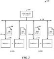
- FIG. 2 illustrates a security system 200 that includes a certificate authority 202 for certificate generation and administration over multiple zones.
- the certificate authority 202 can now be a single (the only) authority deployed to generate and administer (issue) digital certificates for IPsec communications over the multiple zones.
- the system 200 includes two zones: a first zone (Zone1), and a second zone (Zone2) (although many more zones can be employed).
- the first zone includes multiple endpoints 204 (Endpoint 11 ,...,Endpoint 1S ) (each of the endpoints 204 being issued a digital certificate) such as a first zone endpoint 206 receiving and utilizing a first zone certificate 208 (Dig Cert 11 ).
- the second zone includes multiple endpoints 210 (Endpoint 21 ,...,Endpoint 2T ) (each of the endpoints 210 being issued a digital certificate) such as a second zone endpoint 212 receiving and utilizing a second zone certificate 214 (Dig Cert 21 ).
- the certificate authority 202 can be the sole certificate authority that provides certificate administration over a network 216 to both the first and second zones and associated endpoints, and possibly as well as to endpoints and zones outside the network 216.
- the endpoints (206 and 212) exchange corresponding digital certificates (208 and 214) over an IPsec connection.
- the first zone endpoint 206 analyzes the second zone certificate 214 for one or more security context attributes, and potentially other attributes, as does the second zone endpoint 212 to the first zone certificate 208.
- the root certificates of the first and second zone endpoints (206 and 212) can also be passed and validated. If validation is successful from both endpoints, an IPsec session can be established between the endpoints (206 and 212).
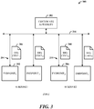
- FIG. 3 illustrates a security system 300 that includes the certificate authority 202 for certificate generation and administration within subzones of a single zone.
- the certificate authority 202 can still be the single (only) authority deployed to generate and administer (issue) digital certificates for IPsec communications and sessions over the multiple subzones (or segments).
- the system 300 includes two subzones of a zone: a first subzone (Subzonel), and a second subzone (Subzone2) (although many more subzones can be employed).
- the first subzone includes the multiple endpoints 204 (Endpoint 11 ,...,Endpoint 1S ) (each endpoint being issued a digital certificate) such as a first subzone endpoint 302 receiving and utilizing a first subzone certificate 304 (Dig Cert 11 ).
- the second subzone includes the multiple endpoints 210 (Endpoint 21 ,...,Endpoint 2T ) (each endpoint being issued a digital certificate) such as a second subzone endpoint 306 receiving and utilizing a second zone certificate 308 (Dig Cert 21 ).
- the certificate authority 202 can be the sole certificate authority for the zone and subzones that provides certificate administration over the network 216 to both the first and second subzones and associated endpoints, and possibly as well as to endpoints and zones/subzones outside the network 216.
- the endpoints (302 and 306) exchange corresponding digital certificates (304 and 308) over an IPsec connection.
- the first subzone endpoint 302 analyzes the second subzone certificate 308 for one or more security context attributes, and potentially other attributes, as does the second subzone endpoint 306 to the first subzone certificate 304.
- the root certificates of the first and second subzone endpoints (302 and 306) can also be passed and validated. If validation is successful from both endpoints, an IPsec session can be established between the endpoints (302 and 306).
- FIG. 4 illustrates exemplary certificate attributes 400 that can be employed in a digital certificate 402 for IPsec communications.
- the attributes 400 can include QoS data, unique ID of the security context, IP address of an endpoint (physical machine or virtual machine) with which an IPsec session can be obtained, IP addresses for a group (or groups) of endpoints with which an IPsec session(s) can be obtained, customer ID (e.g., for a company), zone ID, circle ID, IP address of proxy system, and so on.
- customer ID e.g., for a company
- zone ID e.g., for a company
- circle ID IP address of proxy system
- the disclosed architecture applies to all classes (e.g., individuals requiring proof of identity, organizations, servers, online business transaction, private organization or governmental, etc.) of digital certificates as well.
- the attribute processing of IPsec can process only a single attribute (company ID), or multiple attributes (e.g., company ID and zonel). Additionally, a weighting system can be employed such that a first attribute is given more weight than a third attribute, for example. Alternatively, or in combination therewith, attributes can be ranked according to predetermined criteria, such as a zone attribute being ranked as top priority, followed by customer ID as a lesser priority, and so on.
- an endpoint can include multiple certificates each defining access to different zones and endpoints according to the attributes.
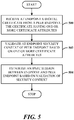
- FIG. 5 illustrates a computer-implemented security method.
- a digital certificate is received at an endpoint from a peer endpoint, the certificate having one or more certificate attributes.
- the security context of the peer endpoint is validated at the endpoint based on the one or more certificate attributes.
- an IPsec session is established between the endpoint and the peer endpoint based on validation of the security context.
- FIG. 6 illustrates additional aspects of the method of FIG. 5 .
- digital certificates are issued to the endpoint and the peer endpoint from a certificate authority that administers multiple zones.
- the certificate is locked down to a specific attribute.
- an attribute is defined as an IP address of a specific endpoint.
- an attribute is defined as a range of IP addresses of a group.
- the security context is defined as one or more of the attributes.
- an attribute of the endpoint digital certificate is compared to security data of the endpoint to validate the peer endpoint to the endpoint.
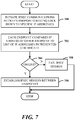
- FIG. 7 illustrates a method of processing an IPsec certificate to an IP address.
- IPsec communications is initiated between endpoints having lock down to a specific IP addresses.
- each endpoint compares the IP address of the other endpoint to a list of IP addresses in the presented certificate.
- flow is to 706, to establish the IPsec session between the endpoints.
- flow is to 708 to fail start of the IPsec session.
- a component can be, but is not limited to being, a process running on a processor, a processor, a hard disk drive, multiple storage drives (of optical, solid state, and/or magnetic storage medium), an object, an executable, a thread of execution, a program, and/or a computer.
- a component can be, but is not limited to being, a process running on a processor, a processor, a hard disk drive, multiple storage drives (of optical, solid state, and/or magnetic storage medium), an object, an executable, a thread of execution, a program, and/or a computer.
- an application running on a server and the server can be a component.
- One or more components can reside within a process and/or thread of execution, and a component can be localized on one computer and/or distributed between two or more computers.
- the word "exemplary” may be used herein to mean serving as an example, instance, or illustration. Any aspect or design described herein as "exemplary” is not necessarily to be construed as preferred or advantageous
- FIG. 8 there is illustrated a block diagram of a computing system 800 operable to execute attribute processing for IPsec communications in accordance with the disclosed architecture.
- FIG. 8 and the following description are intended to provide a brief, general description of the suitable computing system 800 in which the various aspects can be implemented. While the description above is in the general context of computer-executable instructions that can run on one or more computers, those skilled in the art will recognize that a novel embodiment also can be implemented in combination with other program modules and/or as a combination of hardware and software.
- the computing system 800 for implementing various aspects includes the computer 802 having processing unit(s) 804, a computer-readable storage such as a system memory 806, and a system bus 808.
- the processing unit(s) 804 can be any of various commercially available processors such as single-processor, multi-processor, single-core units and multi-core units.
- processors such as single-processor, multi-processor, single-core units and multi-core units.
- processors such as single-processor, multi-processor, single-core units and multi-core units.
- those skilled in the art will appreciate that the novel methods can be practiced with other computer system configurations, including minicomputers, mainframe computers, as well as personal computers (e.g., desktop, laptop, etc.), hand-held computing devices, microprocessor-based or programmable consumer electronics, and the like, each of which can be operatively coupled to one or more associated devices.
- the system memory 806 can include computer-readable storage such as a volatile (VOL) memory 810 (e.g., random access memory (RAM)) and non-volatile memory (NON-VOL) 812 (e.g., ROM, EPROM, EEPROM, etc.).
- VOL volatile
- NON-VOL non-volatile memory
- a basic input/output system (BIOS) can be stored in the non-volatile memory 812, and includes the basic routines that facilitate the communication of data and signals between components within the computer 802, such as during startup.
- the volatile memory 810 can also include a high-speed RAM such as static RAM for caching data.
- the system bus 808 provides an interface for system components including, but not limited to, the memory subsystem 806 to the processing unit(s) 804.
- the system bus 808 can be any of several types of bus structure that can further interconnect to a memory bus (with or without a memory controller), and a peripheral bus (e.g., PCI, PCIe, AGP, LPC, etc.), using any of a variety of commercially available bus architectures.
- the computer 802 further includes machine readable storage subsystem(s) 814 and storage interface(s) 816 for interfacing the storage subsystem(s) 814 to the system bus 808 and other desired computer components.
- the storage subsystem(s) 814 can include one or more of a hard disk drive (HDD), a magnetic floppy disk drive (FDD), and/or optical disk storage drive (e.g., a CD-ROM drive DVD drive), for example.
- the storage interface(s) 816 can include interface technologies such as EIDE, ATA, SATA, and IEEE 1394, for example.
- One or more programs and data can be stored in the memory subsystem 806, a removable memory subsystem 818 (e.g., flash drive form factor technology), and/or the storage subsystem(s) 814 (e.g., optical, magnetic, solid state), including an operating system 820, one or more application programs 822, other program modules 824, and program data 826.
- a removable memory subsystem 818 e.g., flash drive form factor technology
- the storage subsystem(s) 814 e.g., optical, magnetic, solid state
- an operating system 820 e.g., one or more application programs 822, other program modules 824, and program data 826.
- the one or more application programs 822, other program modules 824, and program data 826 can include the entities and components of the system 100 of FIG. 1 , the entities and components of the system 200 of FIG. 2 , the entities and components of the system 300 of FIG. 3 , the certificate and attributes of FIG. 4 , and the methods represented by the flow charts of Figures 5-7 , for example.
- programs include routines, methods, data structures, other software components, etc., that perform particular tasks or implement particular abstract data types. All or portions of the operating system 820, applications 822, modules 824, and/or data 826 can also be cached in memory such as the volatile memory 810, for example. It is to be appreciated that the disclosed architecture can be implemented with various commercially available operating systems or combinations of operating systems (e.g., as virtual machines).
- the storage subsystem(s) 814 and memory subsystems (806 and 818) serve as computer readable media for volatile and non-volatile storage of data, data structures, computer-executable instructions, and so forth.
- Computer readable media can be any available media that can be accessed by the computer 802 and includes volatile and non-volatile internal and/or external media that is removable or non-removable. For the computer 802, the media accommodate the storage of data in any suitable digital format. It should be appreciated by those skilled in the art that other types of computer readable media can be employed such as zip drives, magnetic tape, flash memory cards, flash drives, cartridges, and the like, for storing computer executable instructions for performing the novel methods of the disclosed architecture.
- a user can interact with the computer 802, programs, and data using external user input devices 828 such as a keyboard and a mouse.
- Other external user input devices 828 can include a microphone, an IR (infrared) remote control, a joystick, a game pad, camera recognition systems, a stylus pen, touch screen, gesture systems (e.g., eye movement, head movement, etc.), and/or the like.
- the user can interact with the computer 802, programs, and data using onboard user input devices 830 such a touchpad, microphone, keyboard, etc., where the computer 802 is a portable computer, for example.
- I/O device interface(s) 832 are connected to the processing unit(s) 804 through input/output (I/O) device interface(s) 832 via the system bus 808, but can be connected by other interfaces such as a parallel port, IEEE 1394 serial port, a game port, a USB port, an IR interface, etc.
- the I/O device interface(s) 832 also facilitate the use of output peripherals 834 such as printers, audio devices, camera devices, and so on, such as a sound card and/or onboard audio processing capability.
- One or more graphics interface(s) 836 (also commonly referred to as a graphics processing unit (GPU)) provide graphics and video signals between the computer 802 and external display(s) 838 (e.g., LCD, plasma) and/or onboard displays 840 (e.g., for portable computer).
- graphics interface(s) 836 can also be manufactured as part of the computer system board.
- the computer 802 can operate in a networked environment (e.g., IP-based) using logical connections via a wired/wireless communications subsystem 842 to one or more networks and/or other computers.
- the other computers can include workstations, servers, routers, personal computers, microprocessor-based entertainment appliances, peer devices or other common network nodes, and typically include many or all of the elements described relative to the computer 802.
- the logical connections can include wired/wireless connectivity to a local area network (LAN), a wide area network (WAN), hotspot, and so on.
- LAN and WAN networking environments are commonplace in offices and companies and facilitate enterprise-wide computer networks, such as intranets, all of which may connect to a global communications network such as the Internet.
- the computer 802 When used in a networking environment the computer 802 connects to the network via a wired/wireless communication subsystem 842 (e.g., a network interface adapter, onboard transceiver subsystem, etc.) to communicate with wired/wireless networks, wired/wireless printers, wired/wireless input devices 844, and so on.
- the computer 802 can include a modem or other means for establishing communications over the network.
- programs and data relative to the computer 802 can be stored in the remote memory/storage device, as is associated with a distributed system. It will be appreciated that the network connections shown are exemplary and other means of establishing a communications link between the computers can be used.
- the computer 802 is operable to communicate with wired/wireless devices or entities using the radio technologies such as the IEEE 802.xx family of standards, such as wireless devices operatively disposed in wireless communication (e.g., IEEE 802.11 over-the-air modulation techniques) with, for example, a printer, scanner, desktop and/or portable computer, personal digital assistant (PDA), communications satellite, any piece of equipment or location associated with a wirelessly detectable tag (e.g., a kiosk, news stand, restroom), and telephone.
- PDA personal digital assistant
- the communications can be a predefined structure as with a conventional network or simply an ad hoc communication between at least two devices.
- Wi-Fi networks use radio technologies called IEEE 802.11x (a, b, g, etc.) to provide secure, reliable, fast wireless connectivity.
- IEEE 802.11x a, b, g, etc.
- a Wi-Fi network can be used to connect computers to each other, to the Internet, and to wire networks (which use IEEE 802.3-related media and functions).
- the illustrated aspects can also be practiced in distributed computing environments where certain tasks are performed by remote processing devices that are linked through a communications network.
- program modules can be located in local and/or remote systems and/or storage systems.
- the environment 900 includes one or more client(s) 902.
- the client(s) 902 can be hardware and/or software (e.g., threads, processes, computing devices).
- the client(s) 902 can house cookie(s) and/or associated contextual information, for example.
- the environment 900 also includes one or more server(s) 904.
- the server(s) 904 can also be hardware and/or software (e.g., threads, processes, computing devices).
- the servers 904 can house threads to perform transformations by employing the architecture, for example.
- One possible communication between a client 902 and a server 904 can be in the form of a data packet adapted to be transmitted between two or more computer processes.
- the data packet may include a cookie and/or associated contextual information, for example.
- the environment 900 includes a communication framework 906 (e.g., a global communication network such as the Internet) that can be employed to facilitate communications between the client(s) 902 and the server(s) 904.
- a communication framework 906 e.g., a global communication network such as the Internet
- Communications can be facilitated via a wire (including optical fiber) and/or wireless technology.
- the client(s) 902 are operatively connected to one or more client data store(s) 908 that can be employed to store information local to the client(s) 902 (e.g., cookie(s) and/or associated contextual information).
- the server(s) 904 are operatively connected to one or more server data store(s) 910 that can be employed to store information local to the servers 904.
Landscapes
- Engineering & Computer Science (AREA)
- Computer Security & Cryptography (AREA)
- Computer Networks & Wireless Communication (AREA)
- Signal Processing (AREA)
- Computer Hardware Design (AREA)
- Computing Systems (AREA)
- General Engineering & Computer Science (AREA)
- Data Exchanges In Wide-Area Networks (AREA)
- Information Transfer Between Computers (AREA)
- Computer And Data Communications (AREA)
Description
- Internet protocol security (IPsec) offers authentication and encryption services to IP packets, as well as mutual authentication of communicating peers. IPsec communication between two peer endpoints typically involves two phases: mutual authentication and negotiation of traffic protection parameters, and application of the protection parameters to the traffic between the peers (e.g., encryption and/or authentication). In the first phase, one technique for the peers to authenticate each other is through the use of certificates. Each peer endpoint of the connection is provided with a certificate that authorizes the corresponding endpoint to participate in an IPsec session with the other endpoint. In order for the two endpoints to establish a certificate-based IPsec session, both machines need to have a certificate from a common trusted certificate authority.
FromUS 2009/002-5080 A1 , a method for authenticating a client to a server accessible through an Internet protocol security virtual private network appliance is known. The Internet protocol security virtual private network appliance and an SSL virtual private network appliance are configured to receive an initialization command from the client and the SSL VPN appliance being in communication with an authentication appliance for authenticating the appliance to the server. In response to the initialization command, the authentication appliance generates a client key pair including a client private key and a client public key. The authentication appliance generates a client certificate and a client IPsec profile. The authentication appliance transmit the client key pair, the client certificate and the client IPsec profile to the client. A secure communications session between the client and the service established. The secure communication session is established through the IPsec virtual private network appliance. Upon recite of the IPsec profile, the communication session between the client and the server is encrypted.
Additionally,US 2006/008-5850 A1 discloses a system and method for ensuring that machines having invalid or corrupt states are restricted from accessing host resources. A quarantine agent located on a client machine acquires statements of health from a plurality of health from a plurality of quarantine policy clients. the quarantine agent packages in the statements and provides the package to a quarantine enforcement client. The quarantine enforcement client sends the package to a quarantine health certificate server with a request for a health certificate. If the client provided
valid statements of health, the health certificate server grants the client health certificate that may be used in IPsec session negotiation. - In some datacenters it may be desirable to establish multiple isolation contexts. For example, an ISP (Internet service provider) can have multiple customers and needs to provide a secure isolated zone for each customer. In order to achieve this isolation with the current infrastructure, the ISP deploys a certificate authority for each zone. The deployment and maintenance of multiple certificate authorities is a time consuming and labor intensive process.
- The following presents a simplified summary in order to provide a basic understanding of some novel embodiments described herein. This summary is not an extensive overview, and it is not intended to identify key/critical elements or to delineate the scope thereof. Its sole purpose is to present some concepts in a simplified form as a prelude to the more detailed description that is presented later.
- The disclosed architecture provides Internet protocol security (IPsec) certificate exchange based on certificate attributes. This enables one IPsec endpoint to validate the security context of another IPsec endpoint certificate by referencing certificate attributes, in addition to the certificate root. By facilitating IPsec certificate exchange using certificate attributes rather than solely certificate roots it is now possible to build multiple isolated network zones using a single certificate authority rather than requiring one certificate authority per zone.
- Moreover, the ability to use certificate attributes during the IPsec certificate exchange can be leveraged for more focused communications. For example, QoS (quality of service) fields can be used to give higher priority to one endpoint over another endpoint.
- Furthermore, certificate attributes can be utilized during the IPsec certificate exchange process to identify the security context of the endpoint. For example, the certificate can contain an attribute that is the unique ID (identifier) of the security context. When a receiving IPsec endpoint receives a request from another endpoint, the receiving endpoint can validate that the security context of the certificate installed on the current machine is the same as the security context of the certificate of the requestor.
- Still further, the IPsec certificate use can be locked down to a single IP or group of IPs. One of the attributes in the IPsec certificate can be the IP address(es) with which it can be used. This prevents the certificate from being copied and reused on another machine that has a different IP address.
- To the accomplishment of the foregoing and related ends, certain illustrative aspects are described herein in connection with the following description and the annexed drawings. These aspects are indicative of the various ways in which the principles disclosed herein can be practiced and all aspects and equivalents thereof are intended to be within the scope of the claimed subject matter. Other advantages and novel features will become apparent from the following detailed description when considered in conjunction with the drawings.
-
-
FIG. 1 illustrates computer-implemented security system in accordance with the disclosed architecture. -
FIG. 2 illustrates a security system that includes a certificate authority for certificate generation and administration over multiple zones. -
FIG. 3 illustrates a security system that includes the certificate authority for certificate generation and administration within subzones of a single zone. -
FIG. 4 illustrates exemplary certificate attributes that can be employed in a digital certificate for IPsec communications. -
FIG. 5 illustrates a computer-implemented security method. -
FIG. 6 illustrates additional aspects of the method ofFIG. 5 . -
FIG. 7 illustrates a method of processing an IPsec certificate to an IP address. -
FIG. 8 illustrates a block diagram of a computing system operable to execute attribute processing for IPsec communications in accordance with the disclosed architecture. -
FIG. 9 illustrates a schematic block diagram of a computing environment that processes certificate attributes for IPsec communications. - The disclosed architecture introduces IPsec (Internet protocol security) certificate exchange based on certificate attributes. This enables two IPsec endpoints each having certificates to validate the security context of the other by referencing certificate attributes, in addition to the certificate root. This creation of multiple isolated network zones is now possible using a single certificate authority rather than requiring one certificate authority per zone.
- Reference is now made to the drawings, wherein like reference numerals are used to refer to like elements throughout. In the following description, for purposes of explanation, numerous specific details are set forth in order to provide a thorough understanding thereof. It may be evident, however, that the novel embodiments can be practiced without these specific details. In other instances, well known structures and devices are shown in block diagram form in order to facilitate a description thereof. The intention is to cover all modifications, equivalents, and alternatives falling within the scope of the claimed subject matter.
-
FIG. 1 illustrates a computer-implementedsecurity system 100 in accordance with the disclosed architecture. Thesystem 100 includes acommunications component 102 of alocal endpoint 104 that receives adigital certificate 106 from aremote endpoint 108. Thecommunications component 102 can include at least the hardware and/or software for sending and receiving data packets. Thedigital certificate 106 includes certificate attributes. Thesystem 100 can also include asecurity component 110 of thelocal endpoint 104 that processes one or more of the certificate attributes to validate IPsec communications with theremote endpoint 108. - In other words, the
system 100 facilitates peer certificate validation during IPsec using certificate attributes rather than of solely based on the root certificate. Each peer certificate includes attributes that describe the security context of the certificate. For example, one of the attributes in the IPsec certificate can be customer ID. - During an IPsec certificate exchange between the endpoints (the
local endpoint 104 sending itscertificate 112 to the remote endpoint 108) each endpoint can examine the attributes of the certificate presented by the peer and make a decision on setting up the IPsec session. In the above example, if the certificate presented by the peer contains the same customer ID, then an IPsec session is allowed. However, both certificates (remote certificate 106 and local certificate 112) still need to be issued by a single certificate authority. This solution utilizes only one certificate authority irrespective of the number of isolation contexts deployed. - Another aspect is the ability to increase security by locking IPsec certificates to a specific IP address or addresses. For example, the certificate can include an IP address (or group of addresses) of the physical network on which the certificate is intended to be used. When opening the IPsec connection, each endpoint compares the actual IP address the other endpoint is using to a list of IP addresses in the presented certificate. If the IP address of the other endpoint is on the list, then the connection can proceed. If the address is not on the list, the connection will fail, since this can be an indication of a hijacking attempt, where the attacker managed to copy the certificate from a legitimate machine to a different (unauthorized) machine, for example. The disclosed architecture provides the capability to detect such attacks, thereby increasing overall security of the solution.
- As previously indicated, the
security component 110 can also validate the IPsec communications using a root certificate. The digital certificate 106 (and certificate 112) includes one or more certificate attributes that define a security context of the digital certificate. Additionally, the digital certificate can be locked to a specific certificate attribute, such as a specific address or group of addresses. Thesecurity component 110 can process certificate attributes according to attribute priority. - In other words, one attribute can be given more weight over another attribute or set of attributes. For example, a QoS (quality of service) attribute can be used to give higher priority to one endpoint over another endpoint. The attribute analysis process can also include comparing certificate attribute(s) to a predetermined set of attributes, and if all attributes match, the IPsec session can be established; however, if only two of the three match, the session fails, or makes at a reduced level of communications.
- The one or more certificate attributes can include an IP address of a proxy system through which an endpoint communicates and/or a zone is located. Note that the peer
remote endpoint 108 can also include similar components (e.g., communications component and security component) as thelocal endpoint 104 for receiving and processing the localdigital certificate 112 or other certificates theremote endpoint 108 may receive from other peer endpoints. -
FIG. 2 illustrates asecurity system 200 that includes acertificate authority 202 for certificate generation and administration over multiple zones. Thecertificate authority 202 can now be a single (the only) authority deployed to generate and administer (issue) digital certificates for IPsec communications over the multiple zones. Here, thesystem 200 includes two zones: a first zone (Zone1), and a second zone (Zone2) (although many more zones can be employed). The first zone includes multiple endpoints 204 (Endpoint11,...,Endpoint1S) (each of the endpoints 204 being issued a digital certificate) such as afirst zone endpoint 206 receiving and utilizing a first zone certificate 208 (Dig Cert11). Similarly, the second zone includes multiple endpoints 210 (Endpoint21,...,Endpoint2T) (each of theendpoints 210 being issued a digital certificate) such as asecond zone endpoint 212 receiving and utilizing a second zone certificate 214 (Dig Cert21). - The
certificate authority 202 can be the sole certificate authority that provides certificate administration over anetwork 216 to both the first and second zones and associated endpoints, and possibly as well as to endpoints and zones outside thenetwork 216. - In operation, if the
first zone endpoint 206 requests an IPsec session with thesecond zone endpoint 212, the endpoints (206 and 212) exchange corresponding digital certificates (208 and 214) over an IPsec connection. Thefirst zone endpoint 206 analyzes thesecond zone certificate 214 for one or more security context attributes, and potentially other attributes, as does thesecond zone endpoint 212 to thefirst zone certificate 208. Additionally, the root certificates of the first and second zone endpoints (206 and 212) can also be passed and validated. If validation is successful from both endpoints, an IPsec session can be established between the endpoints (206 and 212). -
FIG. 3 illustrates asecurity system 300 that includes thecertificate authority 202 for certificate generation and administration within subzones of a single zone. Thecertificate authority 202 can still be the single (only) authority deployed to generate and administer (issue) digital certificates for IPsec communications and sessions over the multiple subzones (or segments). Here, thesystem 300 includes two subzones of a zone: a first subzone (Subzonel), and a second subzone (Subzone2) (although many more subzones can be employed). The first subzone includes the multiple endpoints 204 (Endpoint11,...,Endpoint1S) (each endpoint being issued a digital certificate) such as afirst subzone endpoint 302 receiving and utilizing a first subzone certificate 304 (Dig Cert11). Similarly, the second subzone includes the multiple endpoints 210 (Endpoint21,...,Endpoint2T) (each endpoint being issued a digital certificate) such as asecond subzone endpoint 306 receiving and utilizing a second zone certificate 308 (Dig Cert21). - The
certificate authority 202 can be the sole certificate authority for the zone and subzones that provides certificate administration over thenetwork 216 to both the first and second subzones and associated endpoints, and possibly as well as to endpoints and zones/subzones outside thenetwork 216. - In operation, if the
first subzone endpoint 302 requests an IPsec session with thesecond subzone endpoint 306, the endpoints (302 and 306) exchange corresponding digital certificates (304 and 308) over an IPsec connection. Thefirst subzone endpoint 302 analyzes thesecond subzone certificate 308 for one or more security context attributes, and potentially other attributes, as does thesecond subzone endpoint 306 to thefirst subzone certificate 304. Additionally, the root certificates of the first and second subzone endpoints (302 and 306) can also be passed and validated. If validation is successful from both endpoints, an IPsec session can be established between the endpoints (302 and 306). -
FIG. 4 illustrates exemplary certificate attributes 400 that can be employed in adigital certificate 402 for IPsec communications. As previously indicated, theattributes 400 can include QoS data, unique ID of the security context, IP address of an endpoint (physical machine or virtual machine) with which an IPsec session can be obtained, IP addresses for a group (or groups) of endpoints with which an IPsec session(s) can be obtained, customer ID (e.g., for a company), zone ID, circle ID, IP address of proxy system, and so on. The disclosed architecture applies to all classes (e.g., individuals requiring proof of identity, organizations, servers, online business transaction, private organization or governmental, etc.) of digital certificates as well. - The attribute processing of IPsec can process only a single attribute (company ID), or multiple attributes (e.g., company ID and zonel). Additionally, a weighting system can be employed such that a first attribute is given more weight than a third attribute, for example. Alternatively, or in combination therewith, attributes can be ranked according to predetermined criteria, such as a zone attribute being ranked as top priority, followed by customer ID as a lesser priority, and so on.
- Note that an endpoint can include multiple certificates each defining access to different zones and endpoints according to the attributes.
- Included herein is a set of flow charts representative of exemplary methodologies for performing novel aspects of the disclosed architecture. While, for purposes of simplicity of explanation, the one or more methodologies shown herein, for example, in the form of a flow chart or flow diagram, are shown and described as a series of acts, it is to be understood and appreciated that the methodologies are not limited by the order of acts, as some acts may, in accordance therewith, occur in a different order and/or concurrently with other acts from that shown and described herein. For example, those skilled in the art will understand and appreciate that a methodology could alternatively be represented as a series of interrelated states or events, such as in a state diagram. Moreover, not all acts illustrated in a methodology may be required for a novel implementation.
-
FIG. 5 illustrates a computer-implemented security method. At 500, a digital certificate is received at an endpoint from a peer endpoint, the certificate having one or more certificate attributes. At 502, the security context of the peer endpoint is validated at the endpoint based on the one or more certificate attributes. At 504, an IPsec session is established between the endpoint and the peer endpoint based on validation of the security context. -
FIG. 6 illustrates additional aspects of the method ofFIG. 5 . At 600, digital certificates are issued to the endpoint and the peer endpoint from a certificate authority that administers multiple zones. At 602, the certificate is locked down to a specific attribute. At 604, an attribute is defined as an IP address of a specific endpoint. At 606, an attribute is defined as a range of IP addresses of a group. At 608, the security context is defined as one or more of the attributes. At 610, an attribute of the endpoint digital certificate is compared to security data of the endpoint to validate the peer endpoint to the endpoint. -
FIG. 7 illustrates a method of processing an IPsec certificate to an IP address. At 700, IPsec communications is initiated between endpoints having lock down to a specific IP addresses. At 702, each endpoint compares the IP address of the other endpoint to a list of IP addresses in the presented certificate. At 704, if the IP address is on the list, flow is to 706, to establish the IPsec session between the endpoints. Alternatively, at 704, if the IP address is not on the list, flow is to 708 to fail start of the IPsec session. - As used in this application, the terms "component" and "system" are intended to refer to a computer-related entity, either hardware, a combination of hardware and software, software, or software in execution. For example, a component can be, but is not limited to being, a process running on a processor, a processor, a hard disk drive, multiple storage drives (of optical, solid state, and/or magnetic storage medium), an object, an executable, a thread of execution, a program, and/or a computer. By way of illustration, both an application running on a server and the server can be a component. One or more components can reside within a process and/or thread of execution, and a component can be localized on one computer and/or distributed between two or more computers. The word "exemplary" may be used herein to mean serving as an example, instance, or illustration. Any aspect or design described herein as "exemplary" is not necessarily to be construed as preferred or advantageous over other aspects or designs.
- Referring now to
FIG. 8 , there is illustrated a block diagram of acomputing system 800 operable to execute attribute processing for IPsec communications in accordance with the disclosed architecture. In order to provide additional context for various aspects thereof,FIG. 8 and the following description are intended to provide a brief, general description of thesuitable computing system 800 in which the various aspects can be implemented. While the description above is in the general context of computer-executable instructions that can run on one or more computers, those skilled in the art will recognize that a novel embodiment also can be implemented in combination with other program modules and/or as a combination of hardware and software. - The
computing system 800 for implementing various aspects includes thecomputer 802 having processing unit(s) 804, a computer-readable storage such as asystem memory 806, and asystem bus 808. The processing unit(s) 804 can be any of various commercially available processors such as single-processor, multi-processor, single-core units and multi-core units. Moreover, those skilled in the art will appreciate that the novel methods can be practiced with other computer system configurations, including minicomputers, mainframe computers, as well as personal computers (e.g., desktop, laptop, etc.), hand-held computing devices, microprocessor-based or programmable consumer electronics, and the like, each of which can be operatively coupled to one or more associated devices. - The
system memory 806 can include computer-readable storage such as a volatile (VOL) memory 810 (e.g., random access memory (RAM)) and non-volatile memory (NON-VOL) 812 (e.g., ROM, EPROM, EEPROM, etc.). A basic input/output system (BIOS) can be stored in thenon-volatile memory 812, and includes the basic routines that facilitate the communication of data and signals between components within thecomputer 802, such as during startup. Thevolatile memory 810 can also include a high-speed RAM such as static RAM for caching data. - The
system bus 808 provides an interface for system components including, but not limited to, thememory subsystem 806 to the processing unit(s) 804. Thesystem bus 808 can be any of several types of bus structure that can further interconnect to a memory bus (with or without a memory controller), and a peripheral bus (e.g., PCI, PCIe, AGP, LPC, etc.), using any of a variety of commercially available bus architectures. - The
computer 802 further includes machine readable storage subsystem(s) 814 and storage interface(s) 816 for interfacing the storage subsystem(s) 814 to thesystem bus 808 and other desired computer components. The storage subsystem(s) 814 can include one or more of a hard disk drive (HDD), a magnetic floppy disk drive (FDD), and/or optical disk storage drive (e.g., a CD-ROM drive DVD drive), for example. The storage interface(s) 816 can include interface technologies such as EIDE, ATA, SATA, and IEEE 1394, for example. - One or more programs and data can be stored in the
memory subsystem 806, a removable memory subsystem 818 (e.g., flash drive form factor technology), and/or the storage subsystem(s) 814 (e.g., optical, magnetic, solid state), including anoperating system 820, one ormore application programs 822,other program modules 824, andprogram data 826. - The one or
more application programs 822,other program modules 824, andprogram data 826 can include the entities and components of thesystem 100 ofFIG. 1 , the entities and components of thesystem 200 ofFIG. 2 , the entities and components of thesystem 300 ofFIG. 3 , the certificate and attributes ofFIG. 4 , and the methods represented by the flow charts ofFigures 5-7 , for example. - Generally, programs include routines, methods, data structures, other software components, etc., that perform particular tasks or implement particular abstract data types. All or portions of the
operating system 820,applications 822,modules 824, and/ordata 826 can also be cached in memory such as thevolatile memory 810, for example. It is to be appreciated that the disclosed architecture can be implemented with various commercially available operating systems or combinations of operating systems (e.g., as virtual machines). - The storage subsystem(s) 814 and memory subsystems (806 and 818) serve as computer readable media for volatile and non-volatile storage of data, data structures, computer-executable instructions, and so forth. Computer readable media can be any available media that can be accessed by the
computer 802 and includes volatile and non-volatile internal and/or external media that is removable or non-removable. For thecomputer 802, the media accommodate the storage of data in any suitable digital format. It should be appreciated by those skilled in the art that other types of computer readable media can be employed such as zip drives, magnetic tape, flash memory cards, flash drives, cartridges, and the like, for storing computer executable instructions for performing the novel methods of the disclosed architecture. - A user can interact with the
computer 802, programs, and data using externaluser input devices 828 such as a keyboard and a mouse. Other externaluser input devices 828 can include a microphone, an IR (infrared) remote control, a joystick, a game pad, camera recognition systems, a stylus pen, touch screen, gesture systems (e.g., eye movement, head movement, etc.), and/or the like. The user can interact with thecomputer 802, programs, and data using onboarduser input devices 830 such a touchpad, microphone, keyboard, etc., where thecomputer 802 is a portable computer, for example. These and other input devices are connected to the processing unit(s) 804 through input/output (I/O) device interface(s) 832 via thesystem bus 808, but can be connected by other interfaces such as a parallel port, IEEE 1394 serial port, a game port, a USB port, an IR interface, etc. The I/O device interface(s) 832 also facilitate the use ofoutput peripherals 834 such as printers, audio devices, camera devices, and so on, such as a sound card and/or onboard audio processing capability. - One or more graphics interface(s) 836 (also commonly referred to as a graphics processing unit (GPU)) provide graphics and video signals between the
computer 802 and external display(s) 838 (e.g., LCD, plasma) and/or onboard displays 840 (e.g., for portable computer). The graphics interface(s) 836 can also be manufactured as part of the computer system board. - The
computer 802 can operate in a networked environment (e.g., IP-based) using logical connections via a wired/wireless communications subsystem 842 to one or more networks and/or other computers. The other computers can include workstations, servers, routers, personal computers, microprocessor-based entertainment appliances, peer devices or other common network nodes, and typically include many or all of the elements described relative to thecomputer 802. The logical connections can include wired/wireless connectivity to a local area network (LAN), a wide area network (WAN), hotspot, and so on. LAN and WAN networking environments are commonplace in offices and companies and facilitate enterprise-wide computer networks, such as intranets, all of which may connect to a global communications network such as the Internet. - When used in a networking environment the
computer 802 connects to the network via a wired/wireless communication subsystem 842 (e.g., a network interface adapter, onboard transceiver subsystem, etc.) to communicate with wired/wireless networks, wired/wireless printers, wired/wireless input devices 844, and so on. Thecomputer 802 can include a modem or other means for establishing communications over the network. In a networked environment, programs and data relative to thecomputer 802 can be stored in the remote memory/storage device, as is associated with a distributed system. It will be appreciated that the network connections shown are exemplary and other means of establishing a communications link between the computers can be used. - The
computer 802 is operable to communicate with wired/wireless devices or entities using the radio technologies such as the IEEE 802.xx family of standards, such as wireless devices operatively disposed in wireless communication (e.g., IEEE 802.11 over-the-air modulation techniques) with, for example, a printer, scanner, desktop and/or portable computer, personal digital assistant (PDA), communications satellite, any piece of equipment or location associated with a wirelessly detectable tag (e.g., a kiosk, news stand, restroom), and telephone. This includes at least Wi-Fi (or Wireless Fidelity) for hotspots, WiMax, and Bluetooth™ wireless technologies. Thus, the communications can be a predefined structure as with a conventional network or simply an ad hoc communication between at least two devices. Wi-Fi networks use radio technologies called IEEE 802.11x (a, b, g, etc.) to provide secure, reliable, fast wireless connectivity. A Wi-Fi network can be used to connect computers to each other, to the Internet, and to wire networks (which use IEEE 802.3-related media and functions). - The illustrated aspects can also be practiced in distributed computing environments where certain tasks are performed by remote processing devices that are linked through a communications network. In a distributed computing environment, program modules can be located in local and/or remote systems and/or storage systems.
- Referring now to
FIG. 9 , there is illustrated a schematic block diagram of acomputing environment 900 that processes certificate attributes for IPsec communications. Theenvironment 900 includes one or more client(s) 902. The client(s) 902 can be hardware and/or software (e.g., threads, processes, computing devices). The client(s) 902 can house cookie(s) and/or associated contextual information, for example. - The
environment 900 also includes one or more server(s) 904. The server(s) 904 can also be hardware and/or software (e.g., threads, processes, computing devices). Theservers 904 can house threads to perform transformations by employing the architecture, for example. One possible communication between aclient 902 and aserver 904 can be in the form of a data packet adapted to be transmitted between two or more computer processes. The data packet may include a cookie and/or associated contextual information, for example. Theenvironment 900 includes a communication framework 906 (e.g., a global communication network such as the Internet) that can be employed to facilitate communications between the client(s) 902 and the server(s) 904. - Communications can be facilitated via a wire (including optical fiber) and/or wireless technology. The client(s) 902 are operatively connected to one or more client data store(s) 908 that can be employed to store information local to the client(s) 902 (e.g., cookie(s) and/or associated contextual information). Similarly, the server(s) 904 are operatively connected to one or more server data store(s) 910 that can be employed to store information local to the
servers 904. - What has been described above includes examples of the disclosed architecture. It is, of course, not possible to describe every conceivable combination of components and/or methodologies, but one of ordinary skill in the art may recognize that many further combinations and permutations are possible. Accordingly, the novel architecture is intended to embrace all such alterations, modifications and variations that fall within the scope of the appended claims. Furthermore, to the extent that the term "includes" is used in either the detailed description or the claims, such term is intended to be inclusive in a manner similar to the term "comprising" as "comprising" is interpreted when employed as a transitional word in a claim.
Claims (14)
- A computer-implemented security system (100), comprising:a communications component (102) of a local endpoint (104) that receives a digital certificate (106) from a remote endpoint (108), the digital certificate having certificate attributes; anda security component (110) of the local endpoint that processes the certificate attributes to validate Internet Protocol security, IPsec, communications with the remote endpoint (108);wherein the certificate is an IPsec certificate and characterized in that the certificate attributes include a list comprising an IP address or group of addresses of a physical network on which the certificate is intended to be used;wherein the local endpoint is adapted to compare the actual IP address the remote endpoint is using to the list of IP addresses in the received certificate;wherein, if the IP address of the remote endpoint is on the list, then the IPsec connection can proceed and, if the IP address of the remote endpoint is not on the list, the IPsec connection will fail.
- The system of claim 1, wherein the security component (110) also validates the communications using a root certificate.
- The system of claim 1, wherein the digital certificate (106) includes one or more certificate attributes that define a security context of the digital certificate.
- The system of claim 1, wherein the digital certificate (106) is locked to a specific certificate attribute.
- The system of claim 1, wherein the digital certificate (106) is locked to a specific address or group of addresses.
- The system of claim 1, further comprising a certificate authority (202) that issues the digital certificate and other digital certificates for IPsec communications over multiple zones.
- The system of claim 1, wherein the one or more certificate attributes include an IP address of a proxy system and a zone.
- A computer-implemented security method, comprising:receiving (500) at an endpoint digital certificate (106) from a peer endpoint, the certificate having one or more certificate attributes;validating (502) at the endpoint the security context of the peer endpoint based on the one or more certificate attributes; andestablishing (504) an IPsec session between the endpoint and the peer endpoint based on validation of the security context;wherein the certificate is an IPsec certificate and characterized in that the certificate attributes include a list comprising an IP address or group of addresses of a physical network on which the certificate is intended to be used;wherein the endpoint compares the actual IP address the peer endpoint is using to the list of IP addresses in the received certificate;wherein, if the IP address of the peer endpoint is on the list, then the IPsec connection can proceed and, if the IP address of the peer endpoint is not on the list, the IPsec connection will fail.
- The method of claim 8, further comprising issuing digital certificates (106) to the endpoint and the peer endpoint from a certificate authority (202) that administers multiple zones.
- The method of claim 8, further comprising locking down (602) the certificate to a specific attribute.
- The method of claim 8, further comprising defining (604) an attribute as an IP address of a specific endpoint.
- The method of claim 8, further comprising defining (606) an attribute as a range of IP addresses of a group.
- The method of claim 8, further comprising defining (608) the security context as one or more of the attributes.
- The method of claim 8, further comprising comparing (610) an attribute of the endpoint digital certificate to security data of the endpoint to validate the peer endpoint to the endpoint.
Applications Claiming Priority (2)
| Application Number | Priority Date | Filing Date | Title |
|---|---|---|---|
| US12/616,789 US9912654B2 (en) | 2009-11-12 | 2009-11-12 | IP security certificate exchange based on certificate attributes |
| PCT/US2010/054573 WO2011059774A2 (en) | 2009-11-12 | 2010-10-28 | Ip security certificate exchange based on certificate attributes |
Publications (3)
| Publication Number | Publication Date |
|---|---|
| EP2499778A2 EP2499778A2 (en) | 2012-09-19 |
| EP2499778A4 EP2499778A4 (en) | 2017-01-04 |
| EP2499778B1 true EP2499778B1 (en) | 2019-08-07 |
Family
ID=43975149
Family Applications (1)
| Application Number | Title | Priority Date | Filing Date |
|---|---|---|---|
| EP10830474.2A Active EP2499778B1 (en) | 2009-11-12 | 2010-10-28 | Ip security certificate exchange based on certificate attributes |
Country Status (6)
| Country | Link |
|---|---|
| US (1) | US9912654B2 (en) |
| EP (1) | EP2499778B1 (en) |
| JP (1) | JP5714596B2 (en) |
| KR (1) | KR101791708B1 (en) |
| CN (1) | CN102612820B (en) |
| WO (1) | WO2011059774A2 (en) |
Families Citing this family (6)
| Publication number | Priority date | Publication date | Assignee | Title |
|---|---|---|---|---|
| DE102010044518A1 (en) * | 2010-09-07 | 2012-03-08 | Siemens Aktiengesellschaft | Method for certificate-based authentication |
| JP5880401B2 (en) * | 2012-11-15 | 2016-03-09 | 富士ゼロックス株式会社 | Communication apparatus and program |
| US20160366124A1 (en) * | 2015-06-15 | 2016-12-15 | Qualcomm Incorporated | Configuration and authentication of wireless devices |
| CN106464690B (en) * | 2015-08-24 | 2020-04-10 | 华为技术有限公司 | Security authentication method, configuration method and related equipment |
| KR102250081B1 (en) * | 2019-02-22 | 2021-05-10 | 데이터얼라이언스 주식회사 | Public ledger based autonomous credential management system and method |
| US11783062B2 (en) | 2021-02-16 | 2023-10-10 | Microsoft Technology Licensing, Llc | Risk-based access to computing environment secrets |
Family Cites Families (28)
| Publication number | Priority date | Publication date | Assignee | Title |
|---|---|---|---|---|
| US5530758A (en) * | 1994-06-03 | 1996-06-25 | Motorola, Inc. | Operational methods for a secure node in a computer network |
| US5548646A (en) * | 1994-09-15 | 1996-08-20 | Sun Microsystems, Inc. | System for signatureless transmission and reception of data packets between computer networks |
| CA2228687A1 (en) * | 1998-02-04 | 1999-08-04 | Brett Howard | Secured virtual private networks |
| US7461250B1 (en) * | 1999-07-22 | 2008-12-02 | Rsa Security, Inc. | System and method for certificate exchange |
| GB2357226B (en) * | 1999-12-08 | 2003-07-16 | Hewlett Packard Co | Security protocol |
| AU2001266739A1 (en) * | 2000-06-06 | 2001-12-17 | Bex.Com Pte. Ltd. | Method and apparatus for establishing global trust bridge for multiple trust authorities |
| US7113996B2 (en) * | 2000-07-21 | 2006-09-26 | Sandy Craig Kronenberg | Method and system for secured transport and storage of data on a network |
| EP1325599A1 (en) * | 2000-09-08 | 2003-07-09 | Guy S. Tallent | System and method for providing authorization and other services |
| US6915437B2 (en) * | 2000-12-20 | 2005-07-05 | Microsoft Corporation | System and method for improved network security |
| US7073055B1 (en) * | 2001-02-22 | 2006-07-04 | 3Com Corporation | System and method for providing distributed and dynamic network services for remote access server users |
| US7272714B2 (en) * | 2002-05-31 | 2007-09-18 | International Business Machines Corporation | Method, apparatus, and program for automated trust zone partitioning |
| US7185199B2 (en) * | 2002-08-30 | 2007-02-27 | Xerox Corporation | Apparatus and methods for providing secured communication |
| US20040093492A1 (en) * | 2002-11-13 | 2004-05-13 | Olivier Daude | Virtual private network management with certificates |
| JP4352728B2 (en) | 2003-03-11 | 2009-10-28 | 株式会社日立製作所 | Server apparatus, terminal control apparatus, and terminal authentication method |
| US20040181665A1 (en) * | 2003-03-12 | 2004-09-16 | Houser Daniel D. | Trust governance framework |
| US7308711B2 (en) | 2003-06-06 | 2007-12-11 | Microsoft Corporation | Method and framework for integrating a plurality of network policies |
| US20050086468A1 (en) * | 2003-10-17 | 2005-04-21 | Branislav Meandzija | Digital certificate related to user terminal hardware in a wireless network |
| US20050257045A1 (en) * | 2004-04-12 | 2005-11-17 | Bushman M B | Secure messaging system |
| US20060085850A1 (en) | 2004-10-14 | 2006-04-20 | Microsoft Corporation | System and methods for providing network quarantine using IPsec |
| ZA200508074B (en) | 2004-10-14 | 2007-12-27 | Microsoft Corp | System and methods for providing network quarantine using ipsec |
| KR100759489B1 (en) | 2004-11-18 | 2007-09-18 | 삼성전자주식회사 | Method and appratus for security of ip security tunnel using public key infrastructure in a mobile communication network |
| US20060174125A1 (en) * | 2005-01-31 | 2006-08-03 | Brookner George M | Multiple cryptographic key security device |
| US20080022392A1 (en) * | 2006-07-05 | 2008-01-24 | Cisco Technology, Inc. | Resolution of attribute overlap on authentication, authorization, and accounting servers |
| US20090025080A1 (en) * | 2006-09-27 | 2009-01-22 | Craig Lund | System and method for authenticating a client to a server via an ipsec vpn and facilitating a secure migration to ssl vpn remote access |
| US8429734B2 (en) * | 2007-07-31 | 2013-04-23 | Symantec Corporation | Method for detecting DNS redirects or fraudulent local certificates for SSL sites in pharming/phishing schemes by remote validation and using a credential manager and recorded certificate attributes |
| JP5513410B2 (en) * | 2008-01-18 | 2014-06-04 | アイデントラスト, インコーポレイテッド | Binding digital certificates to multiple trust domains |
| US20100318788A1 (en) * | 2009-06-12 | 2010-12-16 | Alexandro Salvarani | Method of managing secure communications |
| US8250866B2 (en) | 2009-07-30 | 2012-08-28 | Ford Global Technologies, Llc | EGR extraction immediately downstream pre-turbo catalyst |
-
2009
- 2009-11-12 US US12/616,789 patent/US9912654B2/en active Active
-
2010
- 2010-10-28 KR KR1020127012090A patent/KR101791708B1/en active IP Right Grant
- 2010-10-28 CN CN201080051233.4A patent/CN102612820B/en active Active
- 2010-10-28 JP JP2012538846A patent/JP5714596B2/en active Active
- 2010-10-28 EP EP10830474.2A patent/EP2499778B1/en active Active
- 2010-10-28 WO PCT/US2010/054573 patent/WO2011059774A2/en active Application Filing
Non-Patent Citations (1)
| Title |
|---|
| None * |
Also Published As
| Publication number | Publication date |
|---|---|
| US9912654B2 (en) | 2018-03-06 |
| KR101791708B1 (en) | 2017-11-20 |
| WO2011059774A3 (en) | 2011-09-29 |
| US20110113481A1 (en) | 2011-05-12 |
| EP2499778A2 (en) | 2012-09-19 |
| KR20120094926A (en) | 2012-08-27 |
| JP5714596B2 (en) | 2015-05-07 |
| JP2013511209A (en) | 2013-03-28 |
| CN102612820A (en) | 2012-07-25 |
| EP2499778A4 (en) | 2017-01-04 |
| WO2011059774A2 (en) | 2011-05-19 |
| CN102612820B (en) | 2016-03-02 |
Similar Documents
| Publication | Publication Date | Title |
|---|---|---|
| JP5260634B2 (en) | Stepwise authentication system | |
| EP1914658B1 (en) | Identity controlled data center | |
| US7774824B2 (en) | Multifactor device authentication | |
| CN110061842B (en) | Out-of-band remote authentication | |
| US11444932B2 (en) | Device verification of an installation of an email client | |
| US8997196B2 (en) | Flexible end-point compliance and strong authentication for distributed hybrid enterprises | |
| CN113316783A (en) | Two-factor identity authentication using a combination of active directory and one-time password token | |
| US20090199277A1 (en) | Credential arrangement in single-sign-on environment | |
| US20080320566A1 (en) | Device provisioning and domain join emulation over non-secured networks | |
| US20080005359A1 (en) | Method and apparatus for OS independent platform based network access control | |
| EP2499778B1 (en) | Ip security certificate exchange based on certificate attributes | |
| US8272043B2 (en) | Firewall control system | |
| JP7403010B2 (en) | Shared resource identification | |
| US11171964B1 (en) | Authentication using device and user identity | |
| CN114764492A (en) | SDP access control method and system based on block chain | |
| Tiwari et al. | Design and Implementation of Enhanced Security Algorithm for Hybrid Cloud using Kerberos | |
| KR102576357B1 (en) | Zero Trust Security Authentication System | |
| Kasiulynas | Radius Authentication in wireless lab environment |
Legal Events
| Date | Code | Title | Description |
|---|---|---|---|
| PUAI | Public reference made under article 153(3) epc to a published international application that has entered the european phase |
Free format text: ORIGINAL CODE: 0009012 |
|
| 17P | Request for examination filed |
Effective date: 20120509 |
|
| AK | Designated contracting states |
Kind code of ref document: A2 Designated state(s): AL AT BE BG CH CY CZ DE DK EE ES FI FR GB GR HR HU IE IS IT LI LT LU LV MC MK MT NL NO PL PT RO RS SE SI SK SM TR |
|
| DAX | Request for extension of the european patent (deleted) | ||
| REG | Reference to a national code |
Ref country code: HK Ref legal event code: DE Ref document number: 1176190 Country of ref document: HK |
|
| RAP1 | Party data changed (applicant data changed or rights of an application transferred) |
Owner name: MICROSOFT TECHNOLOGY LICENSING, LLC |
|
| REG | Reference to a national code |
Ref country code: DE Ref legal event code: R079 Ref document number: 602010060479 Country of ref document: DE Free format text: PREVIOUS MAIN CLASS: H04L0009320000 Ipc: H04L0029060000 |
|
| A4 | Supplementary search report drawn up and despatched |
Effective date: 20161206 |
|
| RIC1 | Information provided on ipc code assigned before grant |
Ipc: H04L 29/06 20060101AFI20161130BHEP Ipc: H04L 9/32 20060101ALI20161130BHEP |
|
| STAA | Information on the status of an ep patent application or granted ep patent |
Free format text: STATUS: EXAMINATION IS IN PROGRESS |
|
| 17Q | First examination report despatched |
Effective date: 20180607 |
|
| GRAP | Despatch of communication of intention to grant a patent |
Free format text: ORIGINAL CODE: EPIDOSNIGR1 |
|
| STAA | Information on the status of an ep patent application or granted ep patent |
Free format text: STATUS: GRANT OF PATENT IS INTENDED |
|
| INTG | Intention to grant announced |
Effective date: 20181029 |
|
| GRAJ | Information related to disapproval of communication of intention to grant by the applicant or resumption of examination proceedings by the epo deleted |
Free format text: ORIGINAL CODE: EPIDOSDIGR1 |
|
| STAA | Information on the status of an ep patent application or granted ep patent |
Free format text: STATUS: EXAMINATION IS IN PROGRESS |
|
| GRAP | Despatch of communication of intention to grant a patent |
Free format text: ORIGINAL CODE: EPIDOSNIGR1 |
|
| STAA | Information on the status of an ep patent application or granted ep patent |
Free format text: STATUS: GRANT OF PATENT IS INTENDED |
|
| INTC | Intention to grant announced (deleted) | ||
| INTG | Intention to grant announced |
Effective date: 20190307 |
|
| GRAS | Grant fee paid |
Free format text: ORIGINAL CODE: EPIDOSNIGR3 |
|
| GRAA | (expected) grant |
Free format text: ORIGINAL CODE: 0009210 |
|
| STAA | Information on the status of an ep patent application or granted ep patent |
Free format text: STATUS: THE PATENT HAS BEEN GRANTED |
|
| REG | Reference to a national code |
Ref country code: DE Ref legal event code: R082 Ref document number: 602010060479 Country of ref document: DE Representative=s name: GRUENECKER PATENT- UND RECHTSANWAELTE PARTG MB, DE |
|
| AK | Designated contracting states |
Kind code of ref document: B1 Designated state(s): AL AT BE BG CH CY CZ DE DK EE ES FI FR GB GR HR HU IE IS IT LI LT LU LV MC MK MT NL NO PL PT RO RS SE SI SK SM TR |
|
| REG | Reference to a national code |
Ref country code: GB Ref legal event code: FG4D |
|
| REG | Reference to a national code |
Ref country code: CH Ref legal event code: EP Ref country code: AT Ref legal event code: REF Ref document number: 1165577 Country of ref document: AT Kind code of ref document: T Effective date: 20190815 |
|
| REG | Reference to a national code |
Ref country code: DE Ref legal event code: R096 Ref document number: 602010060479 Country of ref document: DE |
|
| REG | Reference to a national code |
Ref country code: IE Ref legal event code: FG4D |
|
| REG | Reference to a national code |
Ref country code: NL Ref legal event code: FP |
|
| REG | Reference to a national code |
Ref country code: LT Ref legal event code: MG4D |
|
| PG25 | Lapsed in a contracting state [announced via postgrant information from national office to epo] |
Ref country code: FI Free format text: LAPSE BECAUSE OF FAILURE TO SUBMIT A TRANSLATION OF THE DESCRIPTION OR TO PAY THE FEE WITHIN THE PRESCRIBED TIME-LIMIT Effective date: 20190807 Ref country code: PT Free format text: LAPSE BECAUSE OF FAILURE TO SUBMIT A TRANSLATION OF THE DESCRIPTION OR TO PAY THE FEE WITHIN THE PRESCRIBED TIME-LIMIT Effective date: 20191209 Ref country code: HR Free format text: LAPSE BECAUSE OF FAILURE TO SUBMIT A TRANSLATION OF THE DESCRIPTION OR TO PAY THE FEE WITHIN THE PRESCRIBED TIME-LIMIT Effective date: 20190807 Ref country code: BG Free format text: LAPSE BECAUSE OF FAILURE TO SUBMIT A TRANSLATION OF THE DESCRIPTION OR TO PAY THE FEE WITHIN THE PRESCRIBED TIME-LIMIT Effective date: 20191107 Ref country code: SE Free format text: LAPSE BECAUSE OF FAILURE TO SUBMIT A TRANSLATION OF THE DESCRIPTION OR TO PAY THE FEE WITHIN THE PRESCRIBED TIME-LIMIT Effective date: 20190807 Ref country code: NO Free format text: LAPSE BECAUSE OF FAILURE TO SUBMIT A TRANSLATION OF THE DESCRIPTION OR TO PAY THE FEE WITHIN THE PRESCRIBED TIME-LIMIT Effective date: 20191107 Ref country code: LT Free format text: LAPSE BECAUSE OF FAILURE TO SUBMIT A TRANSLATION OF THE DESCRIPTION OR TO PAY THE FEE WITHIN THE PRESCRIBED TIME-LIMIT Effective date: 20190807 |
|
| REG | Reference to a national code |
Ref country code: AT Ref legal event code: MK05 Ref document number: 1165577 Country of ref document: AT Kind code of ref document: T Effective date: 20190807 |
|
| PG25 | Lapsed in a contracting state [announced via postgrant information from national office to epo] |
Ref country code: ES Free format text: LAPSE BECAUSE OF FAILURE TO SUBMIT A TRANSLATION OF THE DESCRIPTION OR TO PAY THE FEE WITHIN THE PRESCRIBED TIME-LIMIT Effective date: 20190807 Ref country code: LV Free format text: LAPSE BECAUSE OF FAILURE TO SUBMIT A TRANSLATION OF THE DESCRIPTION OR TO PAY THE FEE WITHIN THE PRESCRIBED TIME-LIMIT Effective date: 20190807 Ref country code: AL Free format text: LAPSE BECAUSE OF FAILURE TO SUBMIT A TRANSLATION OF THE DESCRIPTION OR TO PAY THE FEE WITHIN THE PRESCRIBED TIME-LIMIT Effective date: 20190807 Ref country code: GR Free format text: LAPSE BECAUSE OF FAILURE TO SUBMIT A TRANSLATION OF THE DESCRIPTION OR TO PAY THE FEE WITHIN THE PRESCRIBED TIME-LIMIT Effective date: 20191108 Ref country code: RS Free format text: LAPSE BECAUSE OF FAILURE TO SUBMIT A TRANSLATION OF THE DESCRIPTION OR TO PAY THE FEE WITHIN THE PRESCRIBED TIME-LIMIT Effective date: 20190807 Ref country code: IS Free format text: LAPSE BECAUSE OF FAILURE TO SUBMIT A TRANSLATION OF THE DESCRIPTION OR TO PAY THE FEE WITHIN THE PRESCRIBED TIME-LIMIT Effective date: 20191207 |
|
| PG25 | Lapsed in a contracting state [announced via postgrant information from national office to epo] |
Ref country code: TR Free format text: LAPSE BECAUSE OF FAILURE TO SUBMIT A TRANSLATION OF THE DESCRIPTION OR TO PAY THE FEE WITHIN THE PRESCRIBED TIME-LIMIT Effective date: 20190807 |
|
| PG25 | Lapsed in a contracting state [announced via postgrant information from national office to epo] |
Ref country code: IT Free format text: LAPSE BECAUSE OF FAILURE TO SUBMIT A TRANSLATION OF THE DESCRIPTION OR TO PAY THE FEE WITHIN THE PRESCRIBED TIME-LIMIT Effective date: 20190807 Ref country code: EE Free format text: LAPSE BECAUSE OF FAILURE TO SUBMIT A TRANSLATION OF THE DESCRIPTION OR TO PAY THE FEE WITHIN THE PRESCRIBED TIME-LIMIT Effective date: 20190807 Ref country code: PL Free format text: LAPSE BECAUSE OF FAILURE TO SUBMIT A TRANSLATION OF THE DESCRIPTION OR TO PAY THE FEE WITHIN THE PRESCRIBED TIME-LIMIT Effective date: 20190807 Ref country code: RO Free format text: LAPSE BECAUSE OF FAILURE TO SUBMIT A TRANSLATION OF THE DESCRIPTION OR TO PAY THE FEE WITHIN THE PRESCRIBED TIME-LIMIT Effective date: 20190807 Ref country code: AT Free format text: LAPSE BECAUSE OF FAILURE TO SUBMIT A TRANSLATION OF THE DESCRIPTION OR TO PAY THE FEE WITHIN THE PRESCRIBED TIME-LIMIT Effective date: 20190807 Ref country code: DK Free format text: LAPSE BECAUSE OF FAILURE TO SUBMIT A TRANSLATION OF THE DESCRIPTION OR TO PAY THE FEE WITHIN THE PRESCRIBED TIME-LIMIT Effective date: 20190807 |
|
| PG25 | Lapsed in a contracting state [announced via postgrant information from national office to epo] |
Ref country code: CZ Free format text: LAPSE BECAUSE OF FAILURE TO SUBMIT A TRANSLATION OF THE DESCRIPTION OR TO PAY THE FEE WITHIN THE PRESCRIBED TIME-LIMIT Effective date: 20190807 Ref country code: SK Free format text: LAPSE BECAUSE OF FAILURE TO SUBMIT A TRANSLATION OF THE DESCRIPTION OR TO PAY THE FEE WITHIN THE PRESCRIBED TIME-LIMIT Effective date: 20190807 Ref country code: SM Free format text: LAPSE BECAUSE OF FAILURE TO SUBMIT A TRANSLATION OF THE DESCRIPTION OR TO PAY THE FEE WITHIN THE PRESCRIBED TIME-LIMIT Effective date: 20190807 Ref country code: IS Free format text: LAPSE BECAUSE OF FAILURE TO SUBMIT A TRANSLATION OF THE DESCRIPTION OR TO PAY THE FEE WITHIN THE PRESCRIBED TIME-LIMIT Effective date: 20200224 Ref country code: MC Free format text: LAPSE BECAUSE OF FAILURE TO SUBMIT A TRANSLATION OF THE DESCRIPTION OR TO PAY THE FEE WITHIN THE PRESCRIBED TIME-LIMIT Effective date: 20190807 |
|
| REG | Reference to a national code |
Ref country code: CH Ref legal event code: PL |
|
| REG | Reference to a national code |
Ref country code: DE Ref legal event code: R097 Ref document number: 602010060479 Country of ref document: DE |
|
| REG | Reference to a national code |
Ref country code: HK Ref legal event code: WD Ref document number: 1176190 Country of ref document: HK |
|
| PLBE | No opposition filed within time limit |
Free format text: ORIGINAL CODE: 0009261 |
|
| STAA | Information on the status of an ep patent application or granted ep patent |
Free format text: STATUS: NO OPPOSITION FILED WITHIN TIME LIMIT |
|
| PG2D | Information on lapse in contracting state deleted |
Ref country code: IS |
|
| PG25 | Lapsed in a contracting state [announced via postgrant information from national office to epo] |
Ref country code: CH Free format text: LAPSE BECAUSE OF NON-PAYMENT OF DUE FEES Effective date: 20191031 Ref country code: LU Free format text: LAPSE BECAUSE OF NON-PAYMENT OF DUE FEES Effective date: 20191028 Ref country code: LI Free format text: LAPSE BECAUSE OF NON-PAYMENT OF DUE FEES Effective date: 20191031 |
|
| 26N | No opposition filed |
Effective date: 20200603 |
|
| REG | Reference to a national code |
Ref country code: BE Ref legal event code: MM Effective date: 20191031 |
|
| PG25 | Lapsed in a contracting state [announced via postgrant information from national office to epo] |
Ref country code: BE Free format text: LAPSE BECAUSE OF NON-PAYMENT OF DUE FEES Effective date: 20191031 Ref country code: SI Free format text: LAPSE BECAUSE OF FAILURE TO SUBMIT A TRANSLATION OF THE DESCRIPTION OR TO PAY THE FEE WITHIN THE PRESCRIBED TIME-LIMIT Effective date: 20190807 |
|
| PG25 | Lapsed in a contracting state [announced via postgrant information from national office to epo] |
Ref country code: IE Free format text: LAPSE BECAUSE OF NON-PAYMENT OF DUE FEES Effective date: 20191028 |
|
| PG25 | Lapsed in a contracting state [announced via postgrant information from national office to epo] |
Ref country code: CY Free format text: LAPSE BECAUSE OF FAILURE TO SUBMIT A TRANSLATION OF THE DESCRIPTION OR TO PAY THE FEE WITHIN THE PRESCRIBED TIME-LIMIT Effective date: 20190807 |
|
| PG25 | Lapsed in a contracting state [announced via postgrant information from national office to epo] |
Ref country code: MT Free format text: LAPSE BECAUSE OF FAILURE TO SUBMIT A TRANSLATION OF THE DESCRIPTION OR TO PAY THE FEE WITHIN THE PRESCRIBED TIME-LIMIT Effective date: 20190807 Ref country code: HU Free format text: LAPSE BECAUSE OF FAILURE TO SUBMIT A TRANSLATION OF THE DESCRIPTION OR TO PAY THE FEE WITHIN THE PRESCRIBED TIME-LIMIT; INVALID AB INITIO Effective date: 20101028 |
|
| REG | Reference to a national code |
Ref country code: DE Ref legal event code: R079 Ref document number: 602010060479 Country of ref document: DE Free format text: PREVIOUS MAIN CLASS: H04L0029060000 Ipc: H04L0065000000 |
|
| PG25 | Lapsed in a contracting state [announced via postgrant information from national office to epo] |
Ref country code: MK Free format text: LAPSE BECAUSE OF FAILURE TO SUBMIT A TRANSLATION OF THE DESCRIPTION OR TO PAY THE FEE WITHIN THE PRESCRIBED TIME-LIMIT Effective date: 20190807 |
|
| P01 | Opt-out of the competence of the unified patent court (upc) registered |
Effective date: 20230505 |
|
| PGFP | Annual fee paid to national office [announced via postgrant information from national office to epo] |
Ref country code: NL Payment date: 20230922 Year of fee payment: 14 Ref country code: GB Payment date: 20230920 Year of fee payment: 14 |
|
| PGFP | Annual fee paid to national office [announced via postgrant information from national office to epo] |
Ref country code: FR Payment date: 20230920 Year of fee payment: 14 |
|
| PGFP | Annual fee paid to national office [announced via postgrant information from national office to epo] |
Ref country code: DE Payment date: 20230920 Year of fee payment: 14 |