EP2497424A1 - Radiographic imaging method and apparatus. - Google Patents
Radiographic imaging method and apparatus. Download PDFInfo
- Publication number
- EP2497424A1 EP2497424A1 EP11157111A EP11157111A EP2497424A1 EP 2497424 A1 EP2497424 A1 EP 2497424A1 EP 11157111 A EP11157111 A EP 11157111A EP 11157111 A EP11157111 A EP 11157111A EP 2497424 A1 EP2497424 A1 EP 2497424A1
- Authority
- EP
- European Patent Office
- Prior art keywords
- ray
- image
- interval
- partial
- radiographic apparatus
- Prior art date
- Legal status (The legal status is an assumption and is not a legal conclusion. Google has not performed a legal analysis and makes no representation as to the accuracy of the status listed.)
- Withdrawn
Links
- 238000003384 imaging method Methods 0.000 title claims description 42
- 238000000034 method Methods 0.000 claims abstract description 24
- 238000002601 radiography Methods 0.000 claims abstract description 8
- 230000005855 radiation Effects 0.000 claims description 28
- 230000009466 transformation Effects 0.000 claims description 15
- 230000004888 barrier function Effects 0.000 claims description 13
- 239000000463 material Substances 0.000 claims description 4
- 238000005259 measurement Methods 0.000 description 7
- 230000000694 effects Effects 0.000 description 4
- 238000001514 detection method Methods 0.000 description 3
- 238000005286 illumination Methods 0.000 description 3
- 238000005457 optimization Methods 0.000 description 2
- 239000007787 solid Substances 0.000 description 2
- PXFBZOLANLWPMH-UHFFFAOYSA-N 16-Epiaffinine Natural products C1C(C2=CC=CC=C2N2)=C2C(=O)CC2C(=CC)CN(C)C1C2CO PXFBZOLANLWPMH-UHFFFAOYSA-N 0.000 description 1
- OAICVXFJPJFONN-UHFFFAOYSA-N Phosphorus Chemical compound [P] OAICVXFJPJFONN-UHFFFAOYSA-N 0.000 description 1
- 230000004913 activation Effects 0.000 description 1
- 230000008859 change Effects 0.000 description 1
- 230000001419 dependent effect Effects 0.000 description 1
- 238000012417 linear regression Methods 0.000 description 1
- 230000007246 mechanism Effects 0.000 description 1
- 230000008569 process Effects 0.000 description 1
- 230000001131 transforming effect Effects 0.000 description 1
- 230000000007 visual effect Effects 0.000 description 1
Images

Classifications
-
- A—HUMAN NECESSITIES
- A61—MEDICAL OR VETERINARY SCIENCE; HYGIENE
- A61B—DIAGNOSIS; SURGERY; IDENTIFICATION
- A61B6/00—Apparatus or devices for radiation diagnosis; Apparatus or devices for radiation diagnosis combined with radiation therapy equipment
- A61B6/52—Devices using data or image processing specially adapted for radiation diagnosis
-
- A—HUMAN NECESSITIES
- A61—MEDICAL OR VETERINARY SCIENCE; HYGIENE
- A61B—DIAGNOSIS; SURGERY; IDENTIFICATION
- A61B6/00—Apparatus or devices for radiation diagnosis; Apparatus or devices for radiation diagnosis combined with radiation therapy equipment
- A61B6/06—Diaphragms
-
- A—HUMAN NECESSITIES
- A61—MEDICAL OR VETERINARY SCIENCE; HYGIENE
- A61B—DIAGNOSIS; SURGERY; IDENTIFICATION
- A61B6/00—Apparatus or devices for radiation diagnosis; Apparatus or devices for radiation diagnosis combined with radiation therapy equipment
- A61B6/42—Arrangements for detecting radiation specially adapted for radiation diagnosis
- A61B6/4208—Arrangements for detecting radiation specially adapted for radiation diagnosis characterised by using a particular type of detector
- A61B6/4216—Arrangements for detecting radiation specially adapted for radiation diagnosis characterised by using a particular type of detector using storage phosphor screens
-
- A—HUMAN NECESSITIES
- A61—MEDICAL OR VETERINARY SCIENCE; HYGIENE
- A61B—DIAGNOSIS; SURGERY; IDENTIFICATION
- A61B6/00—Apparatus or devices for radiation diagnosis; Apparatus or devices for radiation diagnosis combined with radiation therapy equipment
- A61B6/42—Arrangements for detecting radiation specially adapted for radiation diagnosis
- A61B6/4208—Arrangements for detecting radiation specially adapted for radiation diagnosis characterised by using a particular type of detector
- A61B6/4233—Arrangements for detecting radiation specially adapted for radiation diagnosis characterised by using a particular type of detector using matrix detectors
-
- A—HUMAN NECESSITIES
- A61—MEDICAL OR VETERINARY SCIENCE; HYGIENE
- A61B—DIAGNOSIS; SURGERY; IDENTIFICATION
- A61B6/00—Apparatus or devices for radiation diagnosis; Apparatus or devices for radiation diagnosis combined with radiation therapy equipment
- A61B6/44—Constructional features of apparatus for radiation diagnosis
- A61B6/4429—Constructional features of apparatus for radiation diagnosis related to the mounting of source units and detector units
- A61B6/4452—Constructional features of apparatus for radiation diagnosis related to the mounting of source units and detector units the source unit and the detector unit being able to move relative to each other
-
- A—HUMAN NECESSITIES
- A61—MEDICAL OR VETERINARY SCIENCE; HYGIENE
- A61B—DIAGNOSIS; SURGERY; IDENTIFICATION
- A61B6/00—Apparatus or devices for radiation diagnosis; Apparatus or devices for radiation diagnosis combined with radiation therapy equipment
- A61B6/44—Constructional features of apparatus for radiation diagnosis
- A61B6/4429—Constructional features of apparatus for radiation diagnosis related to the mounting of source units and detector units
- A61B6/4464—Constructional features of apparatus for radiation diagnosis related to the mounting of source units and detector units the source unit or the detector unit being mounted to ceiling
-
- A—HUMAN NECESSITIES
- A61—MEDICAL OR VETERINARY SCIENCE; HYGIENE
- A61B—DIAGNOSIS; SURGERY; IDENTIFICATION
- A61B6/00—Apparatus or devices for radiation diagnosis; Apparatus or devices for radiation diagnosis combined with radiation therapy equipment
- A61B6/50—Apparatus or devices for radiation diagnosis; Apparatus or devices for radiation diagnosis combined with radiation therapy equipment specially adapted for specific body parts; specially adapted for specific clinical applications
- A61B6/505—Apparatus or devices for radiation diagnosis; Apparatus or devices for radiation diagnosis combined with radiation therapy equipment specially adapted for specific body parts; specially adapted for specific clinical applications for diagnosis of bone
-
- A—HUMAN NECESSITIES
- A61—MEDICAL OR VETERINARY SCIENCE; HYGIENE
- A61B—DIAGNOSIS; SURGERY; IDENTIFICATION
- A61B6/00—Apparatus or devices for radiation diagnosis; Apparatus or devices for radiation diagnosis combined with radiation therapy equipment
- A61B6/52—Devices using data or image processing specially adapted for radiation diagnosis
- A61B6/5211—Devices using data or image processing specially adapted for radiation diagnosis involving processing of medical diagnostic data
- A61B6/5229—Devices using data or image processing specially adapted for radiation diagnosis involving processing of medical diagnostic data combining image data of a patient, e.g. combining a functional image with an anatomical image
- A61B6/5235—Devices using data or image processing specially adapted for radiation diagnosis involving processing of medical diagnostic data combining image data of a patient, e.g. combining a functional image with an anatomical image combining images from the same or different ionising radiation imaging techniques, e.g. PET and CT
- A61B6/5241—Devices using data or image processing specially adapted for radiation diagnosis involving processing of medical diagnostic data combining image data of a patient, e.g. combining a functional image with an anatomical image combining images from the same or different ionising radiation imaging techniques, e.g. PET and CT combining overlapping images of the same imaging modality, e.g. by stitching
-
- G—PHYSICS
- G06—COMPUTING; CALCULATING OR COUNTING
- G06T—IMAGE DATA PROCESSING OR GENERATION, IN GENERAL
- G06T3/00—Geometric image transformations in the plane of the image
- G06T3/18—Image warping, e.g. rearranging pixels individually
-
- G—PHYSICS
- G06—COMPUTING; CALCULATING OR COUNTING
- G06T—IMAGE DATA PROCESSING OR GENERATION, IN GENERAL
- G06T3/00—Geometric image transformations in the plane of the image
- G06T3/40—Scaling of whole images or parts thereof, e.g. expanding or contracting
- G06T3/4038—Image mosaicing, e.g. composing plane images from plane sub-images
-
- G—PHYSICS
- G06—COMPUTING; CALCULATING OR COUNTING
- G06T—IMAGE DATA PROCESSING OR GENERATION, IN GENERAL
- G06T7/00—Image analysis
- G06T7/0002—Inspection of images, e.g. flaw detection
- G06T7/0012—Biomedical image inspection
-
- H—ELECTRICITY
- H04—ELECTRIC COMMUNICATION TECHNIQUE
- H04N—PICTORIAL COMMUNICATION, e.g. TELEVISION
- H04N5/00—Details of television systems
- H04N5/30—Transforming light or analogous information into electric information
- H04N5/32—Transforming X-rays
- H04N5/321—Transforming X-rays with video transmission of fluoroscopic images
- H04N5/325—Image enhancement, e.g. by subtraction techniques using polyenergetic X-rays
Definitions
- the present invention relates to a method and apparatus for generating an x-ray image of an elongate body in direct radiography by generating a plurality of partial x-ray images of said elongated body and by stitching these partial images.
- an x-ray image of an elongate body such as the entire spine or the legs of a patient, may have to be obtained.
- CR Computed Radiography
- IP Imaging Plates
- Each of the imaging plates carries an image of a part of the elongate body.
- the individual imaging plates are read out so as to obtain partial images of the elongate body and finally a long length image is created by stitching these partial images.
- Accurate alignment and measurement can be obtained by superimposing a grid of radiation attenuating material covering the region to be imaged and correcting and aligning the partial images to reconstruct the geometry of said grid.
- DR Digital Radiography
- FPD flat panel detectors
- the elongate image is formed by stitching partial images of the elongate body which are taken at plural positions by moving the position of the FPD.
- a barrier may be placed between the subject and the FPD. This barrier has the purpose to stabilize the subject to minimize movement, to protect the subject from contact with the moving FPD. It can also be used to attach an object with known geometry which in accordance with the present invention is used to align the partial images. Attached to this barrier, multiple rulers can be applied to determine the region to be imaged and the distance of the subject to the barrier.
- the radiation image of an object of known geometry is detected and the information on the geometry of this object in the detected radiation image is used to geometrically correct the individual partial images before stitching.
- the stitch method may again use the geometry of the detected image of the object of known geometry in each of the partial image to stitch the images to form one large image.
- the method of the present invention thus comprises the steps of
- the object of known geometry is a grid consisting of X-ray attenuating wires which intersect at a given interval, preferably the interval is 5 by 5 cm.
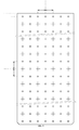
- the object of known geometry may consist of a grid consisting of X-ray attenuating crosses positioned at a given interval, preferably an interval of 5 by 5 cm.
- All crosses are preferably positioned at a first interval of preferably 5 x 5 cm and the crosses of a second type are positioned at a second interval of preferably 10 x 10 cm.
- the geometric transformation used in the present invention is preferably implemented using thin plate spline.
- the invention further discloses a X-ray radiographic apparatus for image creation of an elongate body which comprises:
- a movable diaphragm may be provided to adjust the field of view of the x-ray source.
- the position determining device is capable of generating the positions and, when applicable, also the diaphragm settings of the x-ray generation unit and the x-ray imaging unit such that the field of view area for imaging (the part of the elongate body to be imaged) is captured by a plurality of images acquired by the flat panel detector.
- the processing unit combines the acquired partial images to generate a long length image which is an image of the complete field of view area. For this purpose the processing unit calculates parameters of a geometric transformation expressing the relation between detected positions of locations of the object in a partial radiation image and expected positions of these locations in a partial radiation image. Next the partial images are projected onto a reference plane by applying the geometric transform to its pixels so as to obtain warped partial images. The warped partial images are then stitched so that the image of said object of known geometric dimensions is reconstructed
- All units can be combined in a single device or implemented in different devices.
- the computing unit computes the positions and the diaphragm of the X-ray source and the positions of the flat panel detector.
- the controlling unit positions the X-ray source and flat panel detector and captures the images at each of the positions. The result is a set of images, each capturing a part of the complete field of view area and as a union covering the complete field of view area.
- the method and apparatus of the present invention make use of the radiation image of an object of known geometry present in a partial image to transform the partial image to a representation which is similar to an image taken with a flat panel detector defined in a plane relative to the object of known geometry.
- the object of known geometry at least partially covers each of the field of view areas of each exposure of part of the elongate body.
- the processing unit may detect elements of the object of known geometry and aligns the partial or transformed images in such a way that the part of the object of known geometry is correctly represented in the long length image.
- the method of the present invention is aimed to generate a long length image suitable for length and angle measurements on the imaged subject across an area larger than a single flat-panel-detector.
- the measurements are preferably accurate in all planes, not subjective to errors introduced by the parallax effect. Due to the so-called parallax effect points residing in a different plane are projected differently if the illumination (radiation) source is positioned differently. Not only are objects being projected on different positions in a single reference plane, the projection order may also change for objects in different planes (see the gray area with circles on the left drawing in figure 1 ). To eliminate this effect, it is advisable to position the illumination source on the same location when taking different partial images. However, even when the illumination source position is not fixed, the method of this invention can still be applied.
- a patient barrier may be placed between the patient and the imaging unit. If designed properly, the patient barrier described higher can support the patient to prevent the patient from moving.
- magnification factor can be estimated from the image content for each of the partial images independently. Furthermore, if we know how the object of known geometry is projected on a reference plane close to or in the plane in which the patient is positioned, we can compensate for all perspective and other distortions caused by inaccurate alignment or positioning of the flat panel detector.
- the object of known geometry is in the form of a grid of x-ray attenuating material which can be used to calibrate the individual images and transform them to a reference plane, in one embodiment being the plane of the grid itself.
- this grid should preferably be placed as close as possible to the patient.
- the grid is preferably designed as the object in the patient barrier which supports the patient. In normal imaging conditions, the patient leans against the plate containing the grid, as such the distance between patient and grid is minimal.
- the design of the grid also allows correct image stitching as explained below.
- a controlling unit can be used to co-ordinate the positioning of the X-ray generation unit and the X-ray imaging unit, the preparation of the X-ray imaging unit, the activation of the X-ray generation and read-out of the X-ray imaging unit.
- the optimization is preferably tuned to minimize the complete time for the acquisition of all partial images. All other processing related operations can be postponed to a stage where all images are already acquired.
- a specific embodiment of the image acquisition steps of the method of the present invention are summarized as follows: first the X-ray generation unit and X-ray imaging unit are positioned to a default position which allows the placement of the patient barrier. Secondly, the patient barrier containing a calibration and stitching grid is placed to a position close to the detector and the patient is placed against this patient barrier. Thirdly, after input of the desired area to be imaged, the partial images are acquired (one after the other, as fast as possible to prevent patient movement) and sent to a device which is capable of calibrating and stitching the partial images to generate an elongate (or complete) image. Optionally, this device also allows the generated elongate image to be displayed or corrected before sending it to an archive or diagnostic workstation.
- This module will transform the partial images read out of the detector such that they are projected onto a reference plane which is defined in relation to the object of known geometry. By doing so, the differences in magnification factors and perspective deformations between the partial images can be compensated. After such compensation, the resulting warped images can be stitched together as if they were recorded with the X-ray source positioned at the same location for the different partial images.
- the reference plane is preferably the plane of the grid itself.
- thin plate splines there are many ways to obtain such a transformation, thin plate splines being one them. It is sufficient to detect reference locations in the image of the object of known geometry and map these reference locations to their corresponding location in the above-mentioned reference plane.
- the resulting thin-plate-spline transform consists of the affine transformation and coefficients which model the non-rigid deformation.
- the position of each pixel of this image is mapped to the original image using the thin-plate-spline and the pixel value at the mapped position in the original image is extracted. Because this mapped position will not always correspond with the position of a pixel value, an interpolation technique can be used to estimate the intensity value.
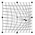
- FIG 6 a geometric transformation is represented for a grid of 3x3 points where the middle point is moved somewhat lower to the right.
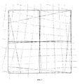
- a more realistic configuration is found in figure 7 .
- the acquired image is represented by the solid gray lines.
- the intersections are mapped to their corresponding coordinates on the grid.
- the geometric transformation is illustrated as the dotted lines which maps the gray lines on the solid black lines in the figure resulting in an almost perfect rectangular reconstruction of the grid. It is obvious that more specific deformation models can be used to estimate the deformation of the grid (e.g. piece-wise linear separable de-skewing as described in EP0919856 ).
- the positions of the grid lines in the partial images can be extracted by low-level operations such as disclosed in patent application EP0866342 .
- a position x,y in the image with intensity value I x , y could be selected as a possible candidate for a cross if the following conditions are true I x + i , y + j ⁇ I x + i + d , y + j I x + j , y + i ⁇ I x + j , y + i + d ⁇ i : 0 ⁇ i ⁇ W 1 ⁇ j : W 2 ⁇ j ⁇ L ⁇ d : d 1 ⁇ d ⁇ d 2 , where W 1 can be interpreted as the central width of the cross lines and W 2 as the total width, L as the length of the lines and d 1 , d 2 as an indication of the size of a region. It is obvious that all these parameters can be tuned to increase the robustness of the detection and that the detection process can be optimized in terms of memory and computation times with
- the known geometry of the object can be used to stitch the images together accurately.
- the object of known geometry can thus be used to combine partial images or to combine transformed partial images.
Landscapes
- Health & Medical Sciences (AREA)
- Life Sciences & Earth Sciences (AREA)
- Engineering & Computer Science (AREA)
- Medical Informatics (AREA)
- Physics & Mathematics (AREA)
- Radiology & Medical Imaging (AREA)
- General Health & Medical Sciences (AREA)
- Nuclear Medicine, Radiotherapy & Molecular Imaging (AREA)
- Surgery (AREA)
- Public Health (AREA)
- Optics & Photonics (AREA)
- Biomedical Technology (AREA)
- Heart & Thoracic Surgery (AREA)
- Molecular Biology (AREA)
- High Energy & Nuclear Physics (AREA)
- Animal Behavior & Ethology (AREA)
- Biophysics (AREA)
- Pathology (AREA)
- Veterinary Medicine (AREA)
- General Physics & Mathematics (AREA)
- Theoretical Computer Science (AREA)
- Computer Vision & Pattern Recognition (AREA)
- Orthopedic Medicine & Surgery (AREA)
- Dentistry (AREA)
- Oral & Maxillofacial Surgery (AREA)
- Mathematical Physics (AREA)
- Quality & Reliability (AREA)
- Apparatus For Radiation Diagnosis (AREA)
Abstract
Method and apparatus for generating an x-ray image of an elongate body in direct radiography by generating a plurality of partial x-ray images of said elongated body and by stitching these partial images.
Description
- The present invention relates to a method and apparatus for generating an x-ray image of an elongate body in direct radiography by generating a plurality of partial x-ray images of said elongated body and by stitching these partial images.
- In X-ray radiography an x-ray image of an elongate body, such as the entire spine or the legs of a patient, may have to be obtained.
- In Computed Radiography (CR), such a long length image is generated by subjecting a number of Imaging Plates (IP), such as photo-stimulable phosphor plates, which are organized in a partially overlapping disposition to an x-ray image of the elongate body. Each of the imaging plates carries an image of a part of the elongate body. After exposure, the individual imaging plates are read out so as to obtain partial images of the elongate body and finally a long length image is created by stitching these partial images. Accurate alignment and measurement can be obtained by superimposing a grid of radiation attenuating material covering the region to be imaged and correcting and aligning the partial images to reconstruct the geometry of said grid. Such methods are described in European patent applications
EP0919856 andEP0866342 . - In recent years, Digital Radiography (DR) has become a valuable alternative for CR. The flat panel detectors (FPD) used in DR are more costly than the IP's for CR, so an alternative to the one-shot long length imaging technique of CR using multiple Imaging Plates is needed. This is achieved by taking plural partial images of an elongate body by moving the position of the FPD while tilting the X-ray tube or moving the X-ray tube parallel to the FPD.
- It is an aspect of the present invention to create an image of the total elongate body from the partial images in an accurate way permitting length and angular measurements on the composed image.
- The above-mentioned aspects are realized by a method and apparatus having the specific features set out in the independent claims.
- Specific features for preferred embodiments of the invention are set out in the dependent claims.
- Further advantages and embodiments of the present invention will become apparent from the following description and drawings.
- Long length images are mostly taken to perform length and angle measurements on the subject across an area larger than a single FPD. It is therefore important to create an image where the alignment of the partial images of the subject and the calibration is accurate.
- In long length imaging, the elongate image is formed by stitching partial images of the elongate body which are taken at plural positions by moving the position of the FPD. In order to support the subject being imaged, a barrier may be placed between the subject and the FPD. This barrier has the purpose to stabilize the subject to minimize movement, to protect the subject from contact with the moving FPD. It can also be used to attach an object with known geometry which in accordance with the present invention is used to align the partial images. Attached to this barrier, multiple rulers can be applied to determine the region to be imaged and the distance of the subject to the barrier.
- According to the method of the present invention the radiation image of an object of known geometry is detected and the information on the geometry of this object in the detected radiation image is used to geometrically correct the individual partial images before stitching. The stitch method may again use the geometry of the detected image of the object of known geometry in each of the partial image to stitch the images to form one large image.
- The method of the present invention thus comprises the steps of
- generating partial radiation images by multiple shot irradiation and read out of a direct radiography detector, each of the partial radiation images comprising part of the radiation image of the elongate body and part of the radiation image of an object of known geometry superimposed on the radiation image of the elongate body,
- calculating parameters of a geometric transformation expressing the relation between detected positions of locations of the object in a partial radiation image and expected positions of the locations in a partial radiation image,
- projecting the partial images onto a reference plane by applying the geometric transform to its pixels so as to obtain warped partial images,
- stitching the warped partial images so that the image of the object of known geometric dimensions is reconstructed.
- In one embodiment the object of known geometry is a grid consisting of X-ray attenuating wires which intersect at a given interval, preferably the interval is 5 by 5 cm.
- Alternatively the object of known geometry may consist of a grid consisting of X-ray attenuating crosses positioned at a given interval, preferably an interval of 5 by 5 cm.
- In a specific embodiment two types of crosses are provided. All crosses are preferably positioned at a first interval of preferably 5 x 5 cm and the crosses of a second type are positioned at a second interval of preferably 10 x 10 cm.
- The geometric transformation used in the present invention is preferably implemented using thin plate spline.
- However, alternative implementations are possible, such as piece-wise linear separable de-skewing.
- The invention further discloses a X-ray radiographic apparatus for image creation of an elongate body which comprises:
- an X-ray imaging unit including an X-ray flat panel detector,
- means for moving said flat panel detector;
- an X-ray generation unit including an X-ray source,
- means for moving said X-ray source,
- an imaging area setting device capable of setting an imaging area for imaging an elongate body;
- a position determination device for determining a plurality of positions for the X-ray generation unit and the X-ray imaging unit, said positions delineating a plurality of partial imaging areas in said imaging area which overlap with a configured amount,
- an object of known geometry provided between said X-ray imaging unit and X-ray generation unit, said object comprising parts of X-ray attenuating material distinguishable in images generated by said X-ray imaging unit;
- at least one control device for controlling said X-ray generation unit and said X-ray imaging unit so that both units are moved sequentially to said positions delineating partial image areas and that partial radiation images of part of said body and part of said object are generated in each of said positions;
- a processing device for generating an elongate image from the generated partial images.
- A movable diaphragm may be provided to adjust the field of view of the x-ray source.
- The position determining device is capable of generating the positions and, when applicable, also the diaphragm settings of the x-ray generation unit and the x-ray imaging unit such that the field of view area for imaging (the part of the elongate body to be imaged) is captured by a plurality of images acquired by the flat panel detector.
- The processing unit combines the acquired partial images to generate a long length image which is an image of the complete field of view area. For this purpose the processing unit calculates parameters of a geometric transformation expressing the relation between detected positions of locations of the object in a partial radiation image and expected positions of these locations in a partial radiation image. Next the partial images are projected onto a reference plane by applying the geometric transform to its pixels so as to obtain warped partial images. The warped partial images are then stitched so that the image of said object of known geometric dimensions is reconstructed
- All units can be combined in a single device or implemented in different devices. In other words, given a desired field of view area as input, the computing unit computes the positions and the diaphragm of the X-ray source and the positions of the flat panel detector. The controlling unit positions the X-ray source and flat panel detector and captures the images at each of the positions. The result is a set of images, each capturing a part of the complete field of view area and as a union covering the complete field of view area.
- The method and apparatus of the present invention make use of the radiation image of an object of known geometry present in a partial image to transform the partial image to a representation which is similar to an image taken with a flat panel detector defined in a plane relative to the object of known geometry.
- The object of known geometry at least partially covers each of the field of view areas of each exposure of part of the elongate body. Based on the known geometry, the processing unit may detect elements of the object of known geometry and aligns the partial or transformed images in such a way that the part of the object of known geometry is correctly represented in the long length image.
-
-
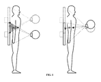
Figure 1 illustrates the parallax effect in the gray area and the different projection order for the circles if the radiation source changes position, -
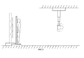
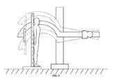
Figure 2 illustrates a radiographic image acquisition device wherein an X-ray generation unit is suspended on the ceiling supporting a vertical movement of the X-ray generation and the X-ray imaging unit and supporting a rotation of the X-ray generation unit, -
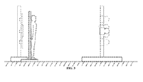
Figure 3 illustrates a radiographic image acquisition apparatus where the X-ray generation unit is mounted on the floor supporting a vertical movement of the X-ray generation and the X-ray imaging unit and supporting a rotation of the X-ray generation unit, -
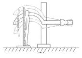
Figure 4 illustrates a radiographic image acquisition apparatus where the X-ray generation unit and X-ray imaging unit is mounted on the floor in a single assembly supporting a vertical movement and rotation of this assembly, -
Figure 5 illustrates a radiographic image acquisition apparatus where the X-ray generation unit and X-ray imaging unit is mounted on the floor in a single assembly supporting a vertical movement and rotation of this assembly in combination with a rotation of the X-ray imaging unit, -
Figure 6 is a representation of a geometric transformation when the middle point in a fixed grid is moved somewhat lower and to the right, -
Figure 7 is a representation of the geometric transformation and the result of a deformed rectangular grid warped back to the original positions, -
Figure 8 is a schematic drawing of a grid consisting of X-ray attenuating wires which intersect at an interval of 5 by 5 cm which can serve as an object of known geometry, -
Figure 9 is a schematic drawing of a grid consisting of X-ray attenuating crosses positioned at an interval of 5 by 5 cm wherein the crosses positioned at an interval of 10 by 10 cm are different in size than the non overlapping crosses positioned at an interval of 5 by 5 cm. - The method of the present invention is aimed to generate a long length image suitable for length and angle measurements on the imaged subject across an area larger than a single flat-panel-detector. The measurements are preferably accurate in all planes, not subjective to errors introduced by the parallax effect. Due to the so-called parallax effect points residing in a different plane are projected differently if the illumination (radiation) source is positioned differently. Not only are objects being projected on different positions in a single reference plane, the projection order may also change for objects in different planes (see the gray area with circles on the left drawing in
figure 1 ). To eliminate this effect, it is advisable to position the illumination source on the same location when taking different partial images. However, even when the illumination source position is not fixed, the method of this invention can still be applied. - To generate an image covering an area bigger than a single flat panel detector for DR, the following options exist: use more than one flat panel detector and stack them similar to the method applied in computed radiography and described e.g. in
EP0919856 or use a special geometry setup for DR such as described inDE102007025448 , or use a single flat panel detector and move it to the different positions so as to record a multiplicity of partial images together covering the area of the elongate body. Since the cost of a single flat panel detector with large dimensions covering the total length of an elongate body currently is too high, the method of moving the flat panel detector so as to record a number of partial images of the elongate body is preferably chosen. Several applicable set-ups for generating such partial images are shown infigures 2 to 5 . - This choice has two main consequences: multiple exposures are taken during a certain time interval and the patient must stand away from the detector to avoid collision. During the time of the exposures, the patient ideally should not move.
- To protect the patient from a collision with the moving imaging unit, a patient barrier may be placed between the patient and the imaging unit. If designed properly, the patient barrier described higher can support the patient to prevent the patient from moving.
- When using such a setup, it is clear that all images will be magnified because of the distance between the patient and the detector. If this distance is known, this magnification factor is computed as

where ERMF stands for Estimated Radiographic Magnification Factor, SID for Source-to-Image Distance and SOD for Source-to-Object Distance where the object represents the patient. The distance between detector and patient (OID) is given by
Often the SOD is not known e.g. because of variations of patient thickness and variations in the placement of the patient barrier with respect to the detector. - If an object of known geometry is captured in each of the exposures generating partial images, the magnification factor can be estimated from the image content for each of the partial images independently. Furthermore, if we know how the object of known geometry is projected on a reference plane close to or in the plane in which the patient is positioned, we can compensate for all perspective and other distortions caused by inaccurate alignment or positioning of the flat panel detector.
- Therefore in one embodiment of the present invention the object of known geometry is in the form of a grid of x-ray attenuating material which can be used to calibrate the individual images and transform them to a reference plane, in one embodiment being the plane of the grid itself.
- To minimize the differences between measurements performed in the grid's reference plane and the measurements of the actual imaged patient object, this grid should preferably be placed as close as possible to the patient. To achieve this, the grid is preferably designed as the object in the patient barrier which supports the patient. In normal imaging conditions, the patient leans against the plate containing the grid, as such the distance between patient and grid is minimal. The design of the grid also allows correct image stitching as explained below.
- Since the partial images are acquired within a certain time interval, it is preferable to optimize and automate the acquisition of the partial images. A controlling unit can be used to co-ordinate the positioning of the X-ray generation unit and the X-ray imaging unit, the preparation of the X-ray imaging unit, the activation of the X-ray generation and read-out of the X-ray imaging unit. The optimization is preferably tuned to minimize the complete time for the acquisition of all partial images. All other processing related operations can be postponed to a stage where all images are already acquired.
- A specific embodiment of the image acquisition steps of the method of the present invention are summarized as follows: first the X-ray generation unit and X-ray imaging unit are positioned to a default position which allows the placement of the patient barrier. Secondly, the patient barrier containing a calibration and stitching grid is placed to a position close to the detector and the patient is placed against this patient barrier. Thirdly, after input of the desired area to be imaged, the partial images are acquired (one after the other, as fast as possible to prevent patient movement) and sent to a device which is capable of calibrating and stitching the partial images to generate an elongate (or complete) image. Optionally, this device also allows the generated elongate image to be displayed or corrected before sending it to an archive or diagnostic workstation.
- This module will transform the partial images read out of the detector such that they are projected onto a reference plane which is defined in relation to the object of known geometry. By doing so, the differences in magnification factors and perspective deformations between the partial images can be compensated. After such compensation, the resulting warped images can be stitched together as if they were recorded with the X-ray source positioned at the same location for the different partial images. In the proposed setup where a grid is used, the reference plane is preferably the plane of the grid itself.
- There are many ways to obtain such a transformation, thin plate splines being one them. It is sufficient to detect reference locations in the image of the object of known geometry and map these reference locations to their corresponding location in the above-mentioned reference plane. The resulting thin-plate-spline transform consists of the affine transformation and coefficients which model the non-rigid deformation.
- Next, to construct the image in the reference plane, the position of each pixel of this image is mapped to the original image using the thin-plate-spline and the pixel value at the mapped position in the original image is extracted. Because this mapped position will not always correspond with the position of a pixel value, an interpolation technique can be used to estimate the intensity value.
- In
figure 6 , a geometric transformation is represented for a grid of 3x3 points where the middle point is moved somewhat lower to the right. A more realistic configuration is found infigure 7 . Here the acquired image is represented by the solid gray lines. Under the assumption that the lines are a representation of a rectangular grid, the intersections are mapped to their corresponding coordinates on the grid. The geometric transformation is illustrated as the dotted lines which maps the gray lines on the solid black lines in the figure resulting in an almost perfect rectangular reconstruction of the grid. It is obvious that more specific deformation models can be used to estimate the deformation of the grid (e.g. piece-wise linear separable de-skewing as described inEP0919856 ). - If the object of known geometry is a grid consisting of X-ray attenuating wires which intersect at a given interval, the positions of the grid lines in the partial images can be extracted by low-level operations such as disclosed in patent application
EP0866342 . - If a grid consisting of X-ray attenuating crosses is used, a position x,y in the image with intensity value Ix,y could be selected as a possible candidate for a cross if the following conditions are true

where W 1 can be interpreted as the central width of the cross lines and W 2 as the total width, L as the length of the lines and d 1, d 2 as an indication of the size of a region. It is obvious that all these parameters can be tuned to increase the robustness of the detection and that the detection process can be optimized in terms of memory and computation times with standard optimization techniques. - Since such a simple detection mechanism may be prune to generate some false positives, one can accumulate the detected positions by means of a Hough transform to find the period of the grid and to reject the false positives. The positions of the crosses can be further optimized by means of linear regression.
- In the previous section is described how to extract and transform objects of known geometry into a reference plane.
- If the same object is present in all the images, the known geometry of the object can be used to stitch the images together accurately.
- Suppose an element, A, of the object is detected in a first partial image and an element, B, of the object is detected in a second partial image. Using the determined deformation fields, both positions are mapped onto A' and B' in the transformed partial images. Positions A' and B' are now defined in the reference plane.
- If the spatial relationship between A' and B' in the reference plane is known, it is easy to position both partial images in such a way that this spatial relationship is preserved in the combined images. The object of known geometry can thus be used to combine partial images or to combine transformed partial images.
- It is furthermore possible to combine transformed partial images on the basis of image information which is not related to the object of known geometry (e.g. visual combination). This may be necessary if the patient has moved between the acquisition of the images.
Claims (26)
- Method of generating a radiation image of an elongate body comprising the steps of- generating partial radiation images by multiple shot irradiation and read out of a direct radiography detector, each of said partial radiation images comprising part of the radiation image of said elongate body and part of the radiation image of an object of known geometric dimensions superimposed on the radiation image of said elongate body,- calculating parameters of a geometric transformation expressing the relation between detected positions of locations of said object in a partial radiation image and expected positions of said locations in a partial radiation image,- projecting said partial images onto a reference plane by applying said geometric transform to its pixels so as to obtain warped partial images,- stitching said warped partial images so that the image of said object of known geometric dimensions is reconstructed.
- A method according to claim 1 wherein said object of known geometric dimensions is a grid consisting of X-ray attenuating wires which intersect at a given interval.
- A method according to claim 2 wherein said interval is 5 by 5 cm.
- A method according to claim 1 wherein said object of known geometry is a grid consisting of X-ray attenuating crosses positioned at a given interval.
- A method according to claim 4 wherein said interval is 5 by 5 cm.
- A method according to claim 4 wherein said crosses comprise crosses of a first and a second type and wherein all crosses are positioned at a first interval and the crosses of a second type are positioned at a second interval.
- A method according to claim 6 wherein said first interval is 5 by 5 cm and said second interval is 10 by 10 cm.
- A method according to claim 1 wherein said geometric transformation is implemented using thin plate spline.
- A method according to claim 1 wherein said geometric transformation is implemented by piece-wise linear separable de-skewing.
- A radiographic apparatus for generating a radiation image of an elongate body comprising:- an X-ray imaging unit including an X-ray flat panel detector,- means for moving said flat panel detector;- an X-ray generation unit including an X-ray source,- means for moving said X-ray source,- an imaging area setting device capable of setting an imaging area for imaging an elongate body;- a position determination device for determining a plurality of positions for the X-ray generation unit and the X-ray imaging unit, said positions delineating a plurality of partial imaging areas in said imaging area which overlap with a configured amount,- an object of known geometry provided between said X-ray imaging unit and X-ray generation unit, said object comprising parts of X-ray attenuating material distinguishable in images generated by said X-ray imaging unit;- at least one control device for controlling said X-ray generation unit and said X-ray imaging unit so that both units are moved sequentially to said positions delineating partial image areas and that partial radiation images of part of said body and part of said object are generated in each of said positions;- a processing device for generating an elongate image from the generated partial images.
- A radiographic apparatus according to claim 10 comprising a diaphragm for collimating the output of said X-ray source.
- A radiographic apparatus according to claim 10, wherein a patient barrier unit is positioned ahead of the X-ray imaging unit supporting said elongate body, the patient barrier unit being capable of supporting, containing or consisting of the object of known geometry.
- A radiographic apparatus according to claim 10, wherein said object of known geometry is a grid consisting of X-ray attenuating wires which intersect at a given interval.
- A radiographic apparatus according to claim 13, wherein said interval is 5 by 5 cm.
- A radiographic apparatus according to claim 10, wherein said object of know geometry is a grid comprising X-ray attenuating crosses positioned at a given interval.
- A radiographic apparatus according to claim 15, wherein said interval is 5 by 5 cm.
- A radiographic apparatus according to claim 15 wherein said crosses comprise crosses of a first and a second type and wherein all crosses are positioned at a first interval and the crosses of a second type are positioned at a second interval.
- A radiographic apparatus according to claim 18, wherein said first interval is 5 by 5 cm and said second interval is 10 by 10 cm.
- A radiographic apparatus according to claim 10, wherein said processing device transforms generated partial images to a reference plane before combining them to an elongate image.
- A radiographic apparatus according to claim 10, wherein said processing device is arranged to generate said elongate image from the generated partial images on the basis of the image of the object of known geometry.
- A radiographic apparatus according to claim 10, wherein said processing device is arranged to- calculate parameters of a geometric transformation expressing the relation between detected positions of locations of said object in a partial radiation image and expected positions of said locations in a partial radiation image, and to- project said partial images onto a reference plane by applying said geometric transform to its pixels so as to obtain warped partial images.
- A radiographic apparatus according to claim 21 wherein said transformation is implemented by using a thin plate spline.
- A radiographic apparatus according to claim 21 wherein said transformation is implemented by using a piece-wise linear separable de-skewing.
- A radiographic apparatus according to claim 20, wherein the processing device combines the transformed partial images based on image information not related to the object of known geometry.
- A radiographic apparatus according to claim 10 wherein said processing device combines said partial images based on image information related to the object of known geometry.
- A radiographic apparatus according to claim 10 wherein said processing device combines said transformed partial images based on image information related to the object of known geometry.
Priority Applications (5)
| Application Number | Priority Date | Filing Date | Title |
|---|---|---|---|
| EP11157111A EP2497424A1 (en) | 2011-03-07 | 2011-03-07 | Radiographic imaging method and apparatus. |
| US13/982,161 US20130315372A1 (en) | 2011-03-07 | 2012-02-22 | Radiographic Imaging Method and Apparatus |
| CN201280011994.6A CN103429157B (en) | 2011-03-07 | 2012-02-22 | radiographic imaging method and apparatus |
| EP12705842.8A EP2683300A1 (en) | 2011-03-07 | 2012-02-22 | Radiographic imaging method and apparatus |
| PCT/EP2012/052991 WO2012119856A1 (en) | 2011-03-07 | 2012-02-22 | Radiographic imaging method and apparatus |
Applications Claiming Priority (1)
| Application Number | Priority Date | Filing Date | Title |
|---|---|---|---|
| EP11157111A EP2497424A1 (en) | 2011-03-07 | 2011-03-07 | Radiographic imaging method and apparatus. |
Publications (1)
| Publication Number | Publication Date |
|---|---|
| EP2497424A1 true EP2497424A1 (en) | 2012-09-12 |
Family
ID=44246364
Family Applications (2)
| Application Number | Title | Priority Date | Filing Date |
|---|---|---|---|
| EP11157111A Withdrawn EP2497424A1 (en) | 2011-03-07 | 2011-03-07 | Radiographic imaging method and apparatus. |
| EP12705842.8A Withdrawn EP2683300A1 (en) | 2011-03-07 | 2012-02-22 | Radiographic imaging method and apparatus |
Family Applications After (1)
| Application Number | Title | Priority Date | Filing Date |
|---|---|---|---|
| EP12705842.8A Withdrawn EP2683300A1 (en) | 2011-03-07 | 2012-02-22 | Radiographic imaging method and apparatus |
Country Status (4)
| Country | Link |
|---|---|
| US (1) | US20130315372A1 (en) |
| EP (2) | EP2497424A1 (en) |
| CN (1) | CN103429157B (en) |
| WO (1) | WO2012119856A1 (en) |
Cited By (2)
| Publication number | Priority date | Publication date | Assignee | Title |
|---|---|---|---|---|
| EP2762081A1 (en) | 2013-02-04 | 2014-08-06 | Agfa Healthcare | Method for accurately generating a radiation image of a region of interest. |
| US9031193B2 (en) | 2011-04-07 | 2015-05-12 | Agfa Healthcare Nv | Method of generating a radiation image of an elongate body |
Families Citing this family (15)
| Publication number | Priority date | Publication date | Assignee | Title |
|---|---|---|---|---|
| DE102011075527A1 (en) * | 2011-05-09 | 2012-11-15 | Fraunhofer-Gesellschaft zur Förderung der angewandten Forschung e.V. | Radiation system and calibration of the same |
| JP5460666B2 (en) * | 2011-09-27 | 2014-04-02 | 富士フイルム株式会社 | Radiation imaging system and long imaging method of radiation imaging system |
| JP6102935B2 (en) * | 2012-10-02 | 2017-03-29 | 株式会社島津製作所 | X-ray equipment |
| DE102013215043A1 (en) * | 2013-07-31 | 2015-02-05 | Siemens Aktiengesellschaft | Method for imaging by means of an X-ray device and X-ray device |
| JP6169626B2 (en) * | 2014-03-10 | 2017-07-26 | 富士フイルム株式会社 | Radiation image processing apparatus, method and program |
| WO2015146526A1 (en) * | 2014-03-24 | 2015-10-01 | 株式会社 日立メディコ | X-ray image acquisition device and elongated imaging method |
| JP6205078B2 (en) | 2014-06-06 | 2017-09-27 | コーニンクレッカ フィリップス エヌ ヴェKoninklijke Philips N.V. | Vertebral level imaging system |
| US10638986B2 (en) * | 2014-11-17 | 2020-05-05 | Carestream Health, Inc. | Modular single shot digital radiography for long-length imaging |
| CN108366772B (en) * | 2015-12-21 | 2023-03-31 | 皇家飞利浦有限公司 | Image processing apparatus and method |
| US10307128B2 (en) * | 2016-05-12 | 2019-06-04 | Shimadzu Corporation | X-ray imaging device |
| US10973473B2 (en) * | 2017-06-27 | 2021-04-13 | Canon Medical Systems Corporation | X-ray diagnostic apparatus |
| DE102017214246B3 (en) | 2017-08-16 | 2018-10-31 | Siemens Healthcare Gmbh | Device and method for fine adjustment of the reconstruction plane of a digital combination image and associated image evaluation system and / or radiology system together with associated computer program product and computer-readable medium |
| JP6906479B2 (en) * | 2018-05-25 | 2021-07-21 | 富士フイルム株式会社 | Bone mineral information acquisition device, method and program |
| CN109480878B (en) * | 2018-12-07 | 2021-01-12 | 上海联影医疗科技股份有限公司 | C-arm X-ray apparatus and method of acquiring X-ray image |
| WO2020198928A1 (en) * | 2019-03-29 | 2020-10-08 | Shenzhen Xpectvision Technology Co., Ltd. | An image sensor having a calibration pattern |
Citations (7)
| Publication number | Priority date | Publication date | Assignee | Title |
|---|---|---|---|---|
| EP0866342A1 (en) | 1997-03-21 | 1998-09-23 | Agfa-Gevaert N.V. | Method of recording and reading a radiation image of an elongate body |
| EP0919856A1 (en) | 1997-12-01 | 1999-06-02 | Agfa-Gevaert N.V. | Method and assembly for recording a radiation image of an elongate body |
| US20020081010A1 (en) * | 2000-12-21 | 2002-06-27 | Chang Yun C. | Method and system for acquiring full spine and full leg images using flat panel digital radiography |
| US20020118793A1 (en) * | 2001-02-28 | 2002-08-29 | Siemens Aktiengesellschaft | Universal X-ray device |
| US20020159564A1 (en) * | 2001-04-30 | 2002-10-31 | Eastman Kodak Company | Mothod for acquiring a radiation image of a long body part using direct digital x-ray detectors |
| DE102007025448A1 (en) | 2007-05-31 | 2008-12-11 | Siemens Ag | X-ray detection system for capturing x-ray photographs of test object, has two digital x-ray detectors with partly closed housing |
| EP2250965A1 (en) * | 2009-05-12 | 2010-11-17 | GE Medical Systems Global Technology Company LLC | Image acquisition method, device and radiography system |
Family Cites Families (8)
| Publication number | Priority date | Publication date | Assignee | Title |
|---|---|---|---|---|
| EP0919858B1 (en) * | 1997-12-01 | 2004-08-25 | Agfa-Gevaert | Method for reconstructing a radiation image of a body from partial radiation images |
| US6273606B1 (en) * | 1997-12-01 | 2001-08-14 | Agfa-Gevaert | Method and assembly for recording a radiation image of an elongate body |
| US6346124B1 (en) * | 1998-08-25 | 2002-02-12 | University Of Florida | Autonomous boundary detection system for echocardiographic images |
| JP2003536134A (en) * | 2000-06-02 | 2003-12-02 | コーニンクレッカ フィリップス エレクトロニクス エヌ ヴィ | Method and apparatus for merging images into a composite image |
| DE10244609A1 (en) * | 2002-09-25 | 2004-04-15 | Siemens Ag | Radiation image recording device |
| US7555100B2 (en) * | 2006-12-20 | 2009-06-30 | Carestream Health, Inc. | Long length imaging using digital radiography |
| DE602008001305D1 (en) * | 2008-01-18 | 2010-07-01 | Mvtec Software Gmbh | System and method for detecting deformable objects |
| CN101238993A (en) * | 2008-02-01 | 2008-08-13 | 哈尔滨工业大学 | Medical ultrasound image registration method based on integer lifting wavelet multiresolution analysis |
-
2011
- 2011-03-07 EP EP11157111A patent/EP2497424A1/en not_active Withdrawn
-
2012
- 2012-02-22 EP EP12705842.8A patent/EP2683300A1/en not_active Withdrawn
- 2012-02-22 CN CN201280011994.6A patent/CN103429157B/en not_active Expired - Fee Related
- 2012-02-22 US US13/982,161 patent/US20130315372A1/en not_active Abandoned
- 2012-02-22 WO PCT/EP2012/052991 patent/WO2012119856A1/en active Application Filing
Patent Citations (7)
| Publication number | Priority date | Publication date | Assignee | Title |
|---|---|---|---|---|
| EP0866342A1 (en) | 1997-03-21 | 1998-09-23 | Agfa-Gevaert N.V. | Method of recording and reading a radiation image of an elongate body |
| EP0919856A1 (en) | 1997-12-01 | 1999-06-02 | Agfa-Gevaert N.V. | Method and assembly for recording a radiation image of an elongate body |
| US20020081010A1 (en) * | 2000-12-21 | 2002-06-27 | Chang Yun C. | Method and system for acquiring full spine and full leg images using flat panel digital radiography |
| US20020118793A1 (en) * | 2001-02-28 | 2002-08-29 | Siemens Aktiengesellschaft | Universal X-ray device |
| US20020159564A1 (en) * | 2001-04-30 | 2002-10-31 | Eastman Kodak Company | Mothod for acquiring a radiation image of a long body part using direct digital x-ray detectors |
| DE102007025448A1 (en) | 2007-05-31 | 2008-12-11 | Siemens Ag | X-ray detection system for capturing x-ray photographs of test object, has two digital x-ray detectors with partly closed housing |
| EP2250965A1 (en) * | 2009-05-12 | 2010-11-17 | GE Medical Systems Global Technology Company LLC | Image acquisition method, device and radiography system |
Cited By (6)
| Publication number | Priority date | Publication date | Assignee | Title |
|---|---|---|---|---|
| US9031193B2 (en) | 2011-04-07 | 2015-05-12 | Agfa Healthcare Nv | Method of generating a radiation image of an elongate body |
| EP2762081A1 (en) | 2013-02-04 | 2014-08-06 | Agfa Healthcare | Method for accurately generating a radiation image of a region of interest. |
| WO2014118369A1 (en) | 2013-02-04 | 2014-08-07 | Agfa Healthcare | Method for accurately generating a radiation image of a region of interest |
| CN104955397A (en) * | 2013-02-04 | 2015-09-30 | 爱克发医疗保健公司 | Method for accurately generating a radiation image of a region of interest |
| US9913621B2 (en) | 2013-02-04 | 2018-03-13 | Agfa Healthcare Nv | Method for accurately generating a radiation image of a region of interest |
| CN104955397B (en) * | 2013-02-04 | 2018-11-09 | 爱克发医疗保健公司 | Method for the radiation image for accurately generating area-of-interest |
Also Published As
| Publication number | Publication date |
|---|---|
| WO2012119856A1 (en) | 2012-09-13 |
| EP2683300A1 (en) | 2014-01-15 |
| US20130315372A1 (en) | 2013-11-28 |
| CN103429157A (en) | 2013-12-04 |
| CN103429157B (en) | 2017-01-18 |
Similar Documents
| Publication | Publication Date | Title |
|---|---|---|
| EP2497424A1 (en) | Radiographic imaging method and apparatus. | |
| JP5501443B2 (en) | Radiation image capturing apparatus, radiation image capturing method, body movement amount measuring method, and program | |
| JP6072102B2 (en) | Radiographic system and radiographic method | |
| CN103181775B (en) | For detecting the method and system of patient body's cursor position | |
| US20110064193A1 (en) | Long length multiple detector imaging apparatus and method | |
| EP1417931A1 (en) | Method for automatically producing true size radiographic image | |
| JP6200839B2 (en) | Breast thickness measuring device, breast thickness measuring method and radiography system | |
| EP2162067B1 (en) | Method for correcting an acquired medical image and medical imager | |
| JP6658578B2 (en) | X-ray equipment | |
| JP5702236B2 (en) | X-ray imaging apparatus and calibration method thereof | |
| CN111466932B (en) | Method and system for camera assisted X-ray imaging | |
| EP2721581B1 (en) | Method to detect and indicate inaccuracies in long length imaging | |
| JP2006141904A (en) | Radiographic apparatus | |
| JP2004275362A (en) | Method of calculating actual size of image, method of measuring image and method of outputting image, and device thereof | |
| US20120027170A1 (en) | Radiological image capturing and displaying method and apparatus | |
| US20190159740A1 (en) | Method for generating a radiation image of a region of interest of an object | |
| US10123757B2 (en) | Image-processing device, radiation image capture system, image-processing method, and computer-readable storage medium | |
| US9913621B2 (en) | Method for accurately generating a radiation image of a region of interest | |
| JP6780065B2 (en) | Radiation imaging system and radiography imaging method | |
| JP2012055474A (en) | Body motion detection device, method and program | |
| JPH0191838A (en) | Weighing phantom for radiation imaging apparatus |
Legal Events
| Date | Code | Title | Description |
|---|---|---|---|
| PUAI | Public reference made under article 153(3) epc to a published international application that has entered the european phase |
Free format text: ORIGINAL CODE: 0009012 |
|
| AK | Designated contracting states |
Kind code of ref document: A1 Designated state(s): AL AT BE BG CH CY CZ DE DK EE ES FI FR GB GR HR HU IE IS IT LI LT LU LV MC MK MT NL NO PL PT RO RS SE SI SK SM TR |
|
| AX | Request for extension of the european patent |
Extension state: BA ME |
|
| 17P | Request for examination filed |
Effective date: 20130312 |
|
| STAA | Information on the status of an ep patent application or granted ep patent |
Free format text: STATUS: THE APPLICATION IS DEEMED TO BE WITHDRAWN |
|
| 18D | Application deemed to be withdrawn |
Effective date: 20130313 |