EP2492162B1 - Tractor - Google Patents
Tractor Download PDFInfo
- Publication number
- EP2492162B1 EP2492162B1 EP12152442.5A EP12152442A EP2492162B1 EP 2492162 B1 EP2492162 B1 EP 2492162B1 EP 12152442 A EP12152442 A EP 12152442A EP 2492162 B1 EP2492162 B1 EP 2492162B1
- Authority
- EP
- European Patent Office
- Prior art keywords
- tractor
- load
- control device
- velocity
- trailer
- Prior art date
- Legal status (The legal status is an assumption and is not a legal conclusion. Google has not performed a legal analysis and makes no representation as to the accuracy of the status listed.)
- Active
Links
- 230000000007 visual effect Effects 0.000 claims description 10
- 239000002689 soil Substances 0.000 description 18
- 238000004519 manufacturing process Methods 0.000 description 4
- 238000005096 rolling process Methods 0.000 description 4
- 230000003068 static effect Effects 0.000 description 4
- 238000010586 diagram Methods 0.000 description 3
- 230000006870 function Effects 0.000 description 3
- 230000000981 bystander Effects 0.000 description 2
- 230000008859 change Effects 0.000 description 2
- 238000002485 combustion reaction Methods 0.000 description 2
- 230000008878 coupling Effects 0.000 description 2
- 238000010168 coupling process Methods 0.000 description 2
- 238000005859 coupling reaction Methods 0.000 description 2
- 230000001939 inductive effect Effects 0.000 description 2
- 239000000463 material Substances 0.000 description 2
- 230000007423 decrease Effects 0.000 description 1
- 238000006073 displacement reaction Methods 0.000 description 1
- 239000003792 electrolyte Substances 0.000 description 1
- 239000000446 fuel Substances 0.000 description 1
- 230000010365 information processing Effects 0.000 description 1
- 239000007788 liquid Substances 0.000 description 1
- 238000000034 method Methods 0.000 description 1
- 230000003287 optical effect Effects 0.000 description 1
- 230000008569 process Effects 0.000 description 1
Images

Classifications
-
- B—PERFORMING OPERATIONS; TRANSPORTING
- B60—VEHICLES IN GENERAL
- B60W—CONJOINT CONTROL OF VEHICLE SUB-UNITS OF DIFFERENT TYPE OR DIFFERENT FUNCTION; CONTROL SYSTEMS SPECIALLY ADAPTED FOR HYBRID VEHICLES; ROAD VEHICLE DRIVE CONTROL SYSTEMS FOR PURPOSES NOT RELATED TO THE CONTROL OF A PARTICULAR SUB-UNIT
- B60W30/00—Purposes of road vehicle drive control systems not related to the control of a particular sub-unit, e.g. of systems using conjoint control of vehicle sub-units
- B60W30/14—Adaptive cruise control
- B60W30/143—Speed control
- B60W30/146—Speed limiting
-
- B—PERFORMING OPERATIONS; TRANSPORTING
- B60—VEHICLES IN GENERAL
- B60W—CONJOINT CONTROL OF VEHICLE SUB-UNITS OF DIFFERENT TYPE OR DIFFERENT FUNCTION; CONTROL SYSTEMS SPECIALLY ADAPTED FOR HYBRID VEHICLES; ROAD VEHICLE DRIVE CONTROL SYSTEMS FOR PURPOSES NOT RELATED TO THE CONTROL OF A PARTICULAR SUB-UNIT
- B60W30/00—Purposes of road vehicle drive control systems not related to the control of a particular sub-unit, e.g. of systems using conjoint control of vehicle sub-units
- B60W30/02—Control of vehicle driving stability
- B60W30/04—Control of vehicle driving stability related to roll-over prevention
-
- B—PERFORMING OPERATIONS; TRANSPORTING
- B60—VEHICLES IN GENERAL
- B60W—CONJOINT CONTROL OF VEHICLE SUB-UNITS OF DIFFERENT TYPE OR DIFFERENT FUNCTION; CONTROL SYSTEMS SPECIALLY ADAPTED FOR HYBRID VEHICLES; ROAD VEHICLE DRIVE CONTROL SYSTEMS FOR PURPOSES NOT RELATED TO THE CONTROL OF A PARTICULAR SUB-UNIT
- B60W50/00—Details of control systems for road vehicle drive control not related to the control of a particular sub-unit, e.g. process diagnostic or vehicle driver interfaces
- B60W50/08—Interaction between the driver and the control system
- B60W50/14—Means for informing the driver, warning the driver or prompting a driver intervention
- B60W2050/143—Alarm means
-
- B—PERFORMING OPERATIONS; TRANSPORTING
- B60—VEHICLES IN GENERAL
- B60W—CONJOINT CONTROL OF VEHICLE SUB-UNITS OF DIFFERENT TYPE OR DIFFERENT FUNCTION; CONTROL SYSTEMS SPECIALLY ADAPTED FOR HYBRID VEHICLES; ROAD VEHICLE DRIVE CONTROL SYSTEMS FOR PURPOSES NOT RELATED TO THE CONTROL OF A PARTICULAR SUB-UNIT
- B60W50/00—Details of control systems for road vehicle drive control not related to the control of a particular sub-unit, e.g. process diagnostic or vehicle driver interfaces
- B60W50/08—Interaction between the driver and the control system
- B60W50/14—Means for informing the driver, warning the driver or prompting a driver intervention
- B60W2050/146—Display means
-
- B—PERFORMING OPERATIONS; TRANSPORTING
- B60—VEHICLES IN GENERAL
- B60W—CONJOINT CONTROL OF VEHICLE SUB-UNITS OF DIFFERENT TYPE OR DIFFERENT FUNCTION; CONTROL SYSTEMS SPECIALLY ADAPTED FOR HYBRID VEHICLES; ROAD VEHICLE DRIVE CONTROL SYSTEMS FOR PURPOSES NOT RELATED TO THE CONTROL OF A PARTICULAR SUB-UNIT
- B60W2530/00—Input parameters relating to vehicle conditions or values, not covered by groups B60W2510/00 or B60W2520/00
- B60W2530/10—Weight
-
- B—PERFORMING OPERATIONS; TRANSPORTING
- B60—VEHICLES IN GENERAL
- B60W—CONJOINT CONTROL OF VEHICLE SUB-UNITS OF DIFFERENT TYPE OR DIFFERENT FUNCTION; CONTROL SYSTEMS SPECIALLY ADAPTED FOR HYBRID VEHICLES; ROAD VEHICLE DRIVE CONTROL SYSTEMS FOR PURPOSES NOT RELATED TO THE CONTROL OF A PARTICULAR SUB-UNIT
- B60W2552/00—Input parameters relating to infrastructure
- B60W2552/15—Road slope, i.e. the inclination of a road segment in the longitudinal direction
-
- B—PERFORMING OPERATIONS; TRANSPORTING
- B60—VEHICLES IN GENERAL
- B60W—CONJOINT CONTROL OF VEHICLE SUB-UNITS OF DIFFERENT TYPE OR DIFFERENT FUNCTION; CONTROL SYSTEMS SPECIALLY ADAPTED FOR HYBRID VEHICLES; ROAD VEHICLE DRIVE CONTROL SYSTEMS FOR PURPOSES NOT RELATED TO THE CONTROL OF A PARTICULAR SUB-UNIT
- B60W2552/00—Input parameters relating to infrastructure
- B60W2552/40—Coefficient of friction
-
- B—PERFORMING OPERATIONS; TRANSPORTING
- B60—VEHICLES IN GENERAL
- B60W—CONJOINT CONTROL OF VEHICLE SUB-UNITS OF DIFFERENT TYPE OR DIFFERENT FUNCTION; CONTROL SYSTEMS SPECIALLY ADAPTED FOR HYBRID VEHICLES; ROAD VEHICLE DRIVE CONTROL SYSTEMS FOR PURPOSES NOT RELATED TO THE CONTROL OF A PARTICULAR SUB-UNIT
- B60W2555/00—Input parameters relating to exterior conditions, not covered by groups B60W2552/00, B60W2554/00
- B60W2555/60—Traffic rules, e.g. speed limits or right of way
-
- B—PERFORMING OPERATIONS; TRANSPORTING
- B60—VEHICLES IN GENERAL
- B60W—CONJOINT CONTROL OF VEHICLE SUB-UNITS OF DIFFERENT TYPE OR DIFFERENT FUNCTION; CONTROL SYSTEMS SPECIALLY ADAPTED FOR HYBRID VEHICLES; ROAD VEHICLE DRIVE CONTROL SYSTEMS FOR PURPOSES NOT RELATED TO THE CONTROL OF A PARTICULAR SUB-UNIT
- B60W2556/00—Input parameters relating to data
- B60W2556/45—External transmission of data to or from the vehicle
- B60W2556/50—External transmission of data to or from the vehicle of positioning data, e.g. GPS [Global Positioning System] data
-
- B—PERFORMING OPERATIONS; TRANSPORTING
- B60—VEHICLES IN GENERAL
- B60Y—INDEXING SCHEME RELATING TO ASPECTS CROSS-CUTTING VEHICLE TECHNOLOGY
- B60Y2200/00—Type of vehicle
- B60Y2200/10—Road Vehicles
- B60Y2200/15—Fork lift trucks, Industrial trucks
Definitions
- the invention relates to a tractor with a loading area and / or a towing device for at least one trailer, the tractor having a control device for limiting a driving speed of the tractor and a load determination device, the load determination device being set up to determine the weight of a load and to provide this information pass on the control device.
- a generic tractor which is provided with wheel load sensors on the four wheels, based on the data of which the load weight of a picked-up load can be determined in a control device in the static state.
- the data of the wheel load sensors can also be used to determine the lateral tipping forces and the longitudinal tipping forces of the tractor in the control device.
- the driving speed can be limited by the control device.
- the in-house goods transport and material flow in particular the material supply of production lines in production plants, is usually carried out by means of trailers on which the goods to be transported, in particular by means of transport containers, pallets or lattice boxes, are transported within the production plant.
- Warehousing industrial trucks designed as tractors are used to pull one or more of these trailers, which are provided with a corresponding towing device to which one or more trailers can be attached.
- Such tractors have compact dimensions, by means of which transport trailers can be safely transported within a production facility on narrow transport routes.
- Tractors are currently used in intralogistics in all operating areas. Both outside areas and inside areas are used. It will Uphill and downhill journeys completed and various loads transported on trailers attached to the towing device and on the loading area of the tractor itself.
- the driver has been tasked with selecting the speed of the tractor so that safe driving and timely braking are possible, depending on the load and soil profile.
- the driver often does not have the option of determining or getting the complete load and floor profile in order to be able to choose a correspondingly safe maximum speed depending on these conditions. Therefore, too high a speed is often chosen, so that there is an accident risk for the driver, bystanders, buildings, facilities and the goods that are to be transported or to be transported. If the speed chosen is too low, transportation is less effective and productive than possible.
- the drivers are often well trained to achieve the safest and most effective transport possible.
- the present invention has for its object to provide a way to control the driving speed of a tractor depending on the load and soil profile.
- the tractor has a soil profile determination device, the soil profile determination device being set up to determine a current soil profile and to pass this information on to the control device, and the control device is set up to determine the driving speed of the tractor as a function of one determined by the load determination device Limit load and a floor profile determined by the floor profile determination device to a maximum permissible driving speed.
- a control device for reducing or limiting and thus for adapting and influencing a driving speed of the tractor is a device which is suitable for specifying a specific target value for the maximum speed of the tractor.
- the target value can preferably be predetermined by giving an instruction to an operator of the tractor.
- the target value can be specified in a particularly preferred manner by intervening in the vehicle control of the tractor in order to adapt the driving speed.
- a load determination device is a device by which the weight of a load to be transported or warped can be determined.
- Loads to be transported or warped can be loads which are provided on the tractor itself, for example on the loading area, trailers attached to the tractor (empty weight) and / or loads located on one or more attached trailers.
- a load determination device can include a scale, for example.
- a load determination device is set up to determine the load with the aid of motor currents, a motor characteristic curve, the vehicle inclination and / or a traction force diagram.
- a traction force diagram shows the course of driving resistance and their sum and the course of the driving force as a function of the driving speed.
- a soil profile determination device is a device that is suitable for determining the current soil profile on which the tractor is located. Components of the floor profile can be, for example, inclines, slopes or bumps. Preferably, the soil profile determination device is also set up to determine whether the tractor is on one level.
- the soil profile determining device is preferably suitable for determining the soil profile as a function of the direction of travel of the tractor. This makes it easy to determine whether the tractor is on an uphill or downhill section, for example.
- the soil profile determination device is preferably suitable for determining the inclination of a tractor in the direction of travel.
- the control device comprises a visual signal generator. This makes it possible to give an operator an indication of a maximum permissible speed of the tractor and / or an exceeding of the maximum permissible speed of the tractor without distracting other people who may be nearby.
- a visual signal generator is a signal generator that is suitable for emitting a signal that can be perceived by an operator of the tractor with one eye.
- a visual signal generator is preferably a lamp or a display.
- the signal can be given, for example, by flashing, lighting up or a change in color of the signal transmitter.
- the signal can particularly preferably be given by the display of a maximum permissible speed in a display.
- the control device comprises an acoustic signal transmitter. This makes it possible to give an operator a signal regardless of the direction in which he is looking.
- An acoustic signal generator is a signal generator that is suitable for emitting a signal that can be perceived by an operator of the tractor with one ear.
- An acoustic signal generator is preferably a horn or a loudspeaker.
- the control device preferably comprises an automatic system that is operatively connected to a travel drive. This makes it possible to limit or reduce the speed of the tractor even if an operator ignores signals.
- Such an automatic system is a device that can carry out processes without the intervention of an operator.
- the automatic is preferably set up Reduce or limit the speed of the tractor, ignoring any operator inputs to the contrary.
- the control device is set up to determine whether the current driving speed exceeds the maximum permissible driving speed and, if the permissible maximum speed is exceeded, in a first step to cause the visual signal generator to emit a signal if the permissible maximum speed is still thereafter is always exceeded, in a second step, to cause the acoustic signal generator to emit a signal and, if the permissible maximum speed is still exceeded afterwards, in a third step to have the automatic speed limitation by the automatic system.
- This makes it possible to first give an operator control over the tractor and only then to intervene automatically in the tractor control if the operator has ignored both the visual and the acoustic signal. This prevents an operator from being surprised by sudden changes in speed and possibly losing his grip or putting the tractor in connection with other industrial trucks in a situation in which a collision is provoked by a sudden change in speed.
- the control device When the driving speed is automatically limited by the automatic system, the control device preferably outputs a control signal to a brake light of the tractor.
- a corresponding brake signal can be generated by a brake light, which indicates to operators of subsequent industrial trucks that the tractor is braking.
- the load determination device is preferably set up to measure a force in a trailer device, in particular a trailer coupling, of the tractor. This allows the load, ie the empty weight, of the attached trailer with its load to be determined in a simple manner.
- the quotient of the force and weight force measured in the hitch corresponds to the sine of the slope.
- the weight is the force that the trailers attached to the tractor and theirs Exercise the charge in the perpendicular.
- the slope is the angle between the route and a horizontal.
- An analog or incremental displacement sensor preferably provided on the towing device as a load determination device.
- the load determination device is set up to measure a force which exerts a load on a loading area of the tractor. This makes it possible to easily determine the weight of a load on the load bed of the tractor.
- the loading area of the tractor is preferably attached in such a way that its weight rests on a pressure sensor or a strain gauge.
- the pressure sensor is preferably a piezoresistive pressure sensor, a piezoelectric pressure sensor, a pressure sensor in the vacuum range, a frequency-analogue pressure sensor, a pressure sensor with Hall element, a capacitive pressure sensor or an inductive pressure sensor.
- An information processing device is preferably set up to determine a weight of the load on the loading area of the tractor from the pressure measured by the pressure sensor or the signal detected by the strain gauge.
- the soil profile determination device has an angle sensor for determining the position of the tractor relative to the vertical. This enables the current position of the tractor to be determined in a simple manner.
- An electronic inclinometer can be used as an angle sensor.
- a height compensator, a capacitive liquid inclination sensor or an electrolyte level is preferably used.
- the soil profile determination device has a receiver for a location system for receiving position information and is set up to use the received position information to retrieve a section of a soil profile from a memory.
- the soil profile data can be provided in a simpler manner since it only has to be determined once.
- systems are used as location systems that enable position determination using RFID transponders, bar code markings, optical markings or light sources.
- the position information is preferably determined by a locating system receiver provided in the tractor.
- the memory is preferably located in the tractor. However, the memory can also be located at another location, in which case both the memory and the tractor are preferably connected to a transmitter and a receiver in order to be able to call up the data in a simple manner.
- control device is set up to control the driving speed of the tractor depending on the nature of the road surface. This makes it possible to determine the maximum driving speed particularly precisely.
- the condition of the road surface preferably includes unevenness in the road surface such as bumps.
- the nature of the road surface particularly preferably includes static friction, sliding friction and / or rolling friction, which the road surface can produce in cooperation with the wheels of the tractor.
- Constant values can be used for static friction, sliding friction and / or rolling friction.
- the data relating to the nature of the road surface can preferably be called up from a memory on the basis of position data.
- the memory can be in the Tug be provided by yourself or at another location. If the memory is provided at another location, both the memory and the tractor are preferably connected to a transmitter and a receiver in order to be able to call up the data in a simple manner.
- Stiction, sliding friction and / or rolling friction can also be determined by sensors located in the tractor.
- a higher vehicle speed can be permitted with increasing static friction or sliding friction.
- the permissible vehicle speed can be reduced as the rolling resistance coefficient increases.
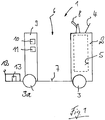
- the Figure 1 shows a side view of a tractor 1 according to the invention.
- the tractor 1 has a front drive part 2, seen in the longitudinal direction of the vehicle, in which at least one steerable drive wheel 3 is arranged.
- a display 4 is arranged on the front drive part 2.
- the tractor 1 has, for example, an electric drive system with an electric travel drive.
- the travel drive comprises an electric travel drive motor which is arranged in the drive part 2 and is no longer shown and is operatively connected to the drive wheel 3.
- An electric steering motor can be provided as the steering drive.
- a battery compartment 5 is arranged in the drive part 2, in which a power supply device of the electric drive system is arranged can, for example a battery block.
- the tractor 1 has a driver's seat 6, which in the exemplary embodiment shown is formed by a standing platform 7.
- the tractor 1 can have a fuel cell as an electrical power supply unit.
- the tractor 1 can have an internal combustion engine drive system with an internal combustion engine.
- a handlebar-like operating arrangement 8 is provided, which is arranged on the top of the drive part 2.
- a frame section 9 delimits the driver's seat 6 at the rear. This rear frame section 9 is provided with load wheels 3a.
- the rear load wheels 3a can be provided as drive wheels and one or two non-driven steering wheels 3 on the front.
- the tractor 1 is equipped with a soil profile determination device 10, 11, which preferably comprises a travel direction inclination sensor 10 and / or a lateral inclination sensor 11.
- the tractor 1 has a hitch 12 designed as a trailer coupling, with which the tractor 1 can be connected to one or more trailers, not shown.
- the towing device 12 is assigned a load determination device 13, which is designed, for example, as a capacitive pressure sensor or strain gauge arranged in the towing device 12.
- the tractor 1 can be provided with a loading area in order to transport loads.
- the tractor 1 has a floor profile determination device 10, 11 formed, for example, by the direction of inclination sensor 10 and the lateral inclination sensor 11, the position of the tractor 1 relative to a vertical can be determined in a simple manner. For example be determined whether the tractor 1 is on an incline or on a downhill section and how strong the incline or descent is.
- a load determination device 13 for example a capacitive pressure sensor or a strain gauge, is provided in the towing device 12 enables the current towing load to be determined.
- the trailer load results from the force exerted on the trailer device 12 by the trailer attached to the trailer device 12. This force increases as a result of loads on the trailers and driving up gradients.
- a control device (not shown in more detail) can determine a maximum permissible speed based on the data determined by the load determination device 13 and the direction of travel sensor as the floor profile determination device 10 and, if this speed is exceeded, cause the display 4 to emit a visual and / or acoustic warning signal, for example in the form of a red one Background and / or a warning tone.
- the control device is also connected to the travel drive of the tractor 11 in order to reduce or limit the travel speed based on the data determined by the load determination device 13 and the direction of travel sensor as the ground profile determination device 10.
- the Figure 2 shows a side view of a tractor 20 on an incline.
- the tractor train 20 consists of a tractor 21 according to the invention and at least one trailer 22.
- the tractor train 20 is located on an incline 23.
- the incline includes an angle ⁇ of, for example, 30 ° with a horizontal line.
- the Indian Figure 2 shown tractor 21 opposite that in the Figure 1 shown, a driver's workplace 6 with a driver's seat and is additionally provided in the rear area with a loading area 25.
- An inclination angle sensor 24 is provided in the tractor 21 as a soil profile determination device.
- the tractor 21 has a hitch 12 designed as a trailer hitch with a pressure sensor, not shown.
- the trailer 22 has a trailer hitch, not shown, with which it is coupled to the trailer device 12 of the tractor 21.
- the inclination angle sensor 24 which is designed as a soil profile determination device, is set up to determine the incline of the incline section 23.
- a load determination device of the towing device 12 for example a pressure sensor or strain gauge, is set up to determine the force that the trailer 22 exerts on the towing device 12.
- the weight force F G of the trailer 22 with the transported load can be divided into two components.
- a first component F N runs perpendicular to the slope 23 and is passed on by the trailer 22 directly to the slope 23. This first component F N can be determined by multiplying the weight force F G by the cosine of the angle ⁇ between the slope 23 and a horizontal line.
- a second component F H runs parallel to the slope 23 and is picked up by the towing device 12 of the tractor 21.
- This second component F H can be determined by multiplying the weight force F G by the sine of the angle ⁇ between the slope 23 and a horizontal line. By measuring this second component F H in the hitch 12 and dividing the result by the sine of the angle ⁇ between the slope 23 and a horizontal line, which is determined by the inclination angle sensor 24, the weight force F G can be determined. If the vehicle inclination ⁇ is known, the weight force F G can also be determined from the motor currents and the motor characteristic of the drive motor (not shown) of the electric travel drive, which is not shown in the tractor 21, and from the tractive force diagram of the tractor 21.
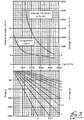
- the Figure 3 shows an upper graphic, which shows the permissible driving speed and distance per hour depending on the tractive force.
- This graphic shows that the permissible driving speed drops from, for example, 16.5 km / h with a pulling force of 0 N to a permissible driving speed of 3.5 km / h with a pulling force of 4500 N.
- the relationship between the permissible driving speed and the tractive force is not linear over the entire range shown.
- a first subrange between a tensile force of 0 N and 600 N the permissible driving speed initially drops approximately linearly to 10 km / h.
- a second section between a tensile force of 600 N and 1800 N, the permissible driving speed drops to 6 km / h.
- the permissible driving speed drops again almost linearly to 3.5 km / h.
- the permissible driving distance per hour is one Tractive force of 1300 N at 6000 m and decreases with increasing tractive force. With a pulling force of 4500 N, the permissible travel distance per hour is 50 m.
- the control device of the tractor uses a predetermined deceleration, for example a desired deceleration of 3.5 m / sec 2 .
- the current tensile force can be determined by the load determination device 13 of the tractor 1.
- the driving speed of the tractor 1, 21 can be automatically limited depending on the respective tractive force.
- the permissible driving distance per hour can be automatically limited or reduced.
- the driver of the tractor 1, 21 can be shown the maximum permissible driving speed and / or driving distance per hour depending on the tractive force. If the maximum permissible driving speed and / or driving distance per hour is exceeded, the driver can be given an acoustic and / or visual signal.
- the lower graphic shows the maximum gradient depending on the trailer load. It also shows the relationship between incline, trailer load and traction. These relationships are shown for trailer loads of 0, 0.5 tons, 1 ton, 1.5 tons, 2 tons, 3 tons, 4 tons, 5 tons and 6 tons. A slope of 0 to 25% is shown. The theoretical tensile force that results is between 0 and 5000 N.
- the required tensile force with a gradient of 0% is 0 N. Up to a gradient of 25%, the tensile force increases linearly to around 2700 N. With a trailer load of 2 t, the pulling force with a gradient of 0% is 500 N. Up to a gradient of 15%, the pulling force increases linearly to around 5000 N. at With a trailer load of 6 t, the pulling force is at an incline of 0% at 1400 N. Up to an incline of 5.5%, the pulling force increases linearly to 5000 N. The curves are based on the assumption of a tensile force of approx. 200N per tonne trailer load.
- the maximum driving speed can be determined with a known trailer load and a known slope without the respective tractive force having to be determined.
- the incline can be determined by a direction of inclination sensor 10 or an inclination angle sensor 24 as a floor profile determination device and transmitted to the vehicle control system or can be called up from a database using position data.
- the driving speed of the tractor 1, 21 can be limited or reduced automatically for a given trailer load or load on a loading platform depending on the incline / slope. If the maximum permissible driving speed is exceeded for a given trailer load or load on a loading platform and driven uphill / downhill, the driver can be given an acoustic or visual signal.
- the tractor according to the invention has a number of advantages.
- the tractor according to the invention enables an optimal driving speed at high Operational safety enables a high transport line. With the tractor according to the invention, safe operation with high transport performance is likewise achieved for a driver with little training.
Landscapes
- Engineering & Computer Science (AREA)
- Automation & Control Theory (AREA)
- Transportation (AREA)
- Mechanical Engineering (AREA)
- Control Of Driving Devices And Active Controlling Of Vehicle (AREA)
- Lifting Devices For Agricultural Implements (AREA)
- Agricultural Machines (AREA)
Description
Die Erfindung betrifft einen Schlepper mit einer Ladefläche und/oder einer Anhängevorrichtung für zumindest einen Anhänger, wobei der Schlepper eine Steuerungseinrichtung zur Begrenzung einer Fahrgeschwindigkeit des Schleppers und eine Lastermittlungseinrichtung aufweist, wobei die Lastermittlungseinrichtung eingerichtet ist, das Gewicht einer Last zu ermitteln und diese Information an die Steuerungseinrichtung weiterzugeben.The invention relates to a tractor with a loading area and / or a towing device for at least one trailer, the tractor having a control device for limiting a driving speed of the tractor and a load determination device, the load determination device being set up to determine the weight of a load and to provide this information pass on the control device.
Aus der
Der innerbetriebliche Warentransport und Materialfluss, insbesondere die Materialversorgung von Produktionslinien in Produktionsbetrieben, erfolgt in der Regel mittels Anhängern, auf denen die zu transportierenden Waren, insbesondere mittels Transportbehälter, Paletten oder Gitterboxen, innerhalb des Produktionsbetriebes transportiert werden.The in-house goods transport and material flow, in particular the material supply of production lines in production plants, is usually carried out by means of trailers on which the goods to be transported, in particular by means of transport containers, pallets or lattice boxes, are transported within the production plant.
Zum Ziehen eines oder mehrerer dieser Anhänger werden als Schlepper ausgebildete Lagertechnikflurförderzeuge verwendet, die mit einer entsprechenden Anhängevorrichtung vorgesehen sind, an die ein oder mehrere Anhänger angehängt werden können. Derartige Schlepper weisen kompakte Abmessungen auf, durch die Transportanhänger innerhalb eines Produktionsbetriebes auf beengten Transportwegen sicher transportiert werden können.Warehousing industrial trucks designed as tractors are used to pull one or more of these trailers, which are provided with a corresponding towing device to which one or more trailers can be attached. Such tractors have compact dimensions, by means of which transport trailers can be safely transported within a production facility on narrow transport routes.
Derzeit werden Schlepper in der Intralogistik in allen Betriebsbereichen eingesetzt. Dabei werden sowohl Außenbereiche als auch Innenbereiche befahren. Es werden Steigung- und Gefällefahrten absolviert und verschiedene Lasten auf an die Anhängevorrichtung angehängten Anhängern und auf der Ladefläche des Schleppers selbst transportiert.Tractors are currently used in intralogistics in all operating areas. Both outside areas and inside areas are used. It will Uphill and downhill journeys completed and various loads transported on trailers attached to the towing device and on the loading area of the tractor itself.
Bei allen Einsatzfällen ist der Fahrer bisher bei der Aufgabe, die Geschwindigkeit des Schleppers so zu wählen, dass in Abhängigkeit von Last und Bodenprofil ein sicheres Fahren und ein rechtzeitiges Abbremsen möglich ist, auf sich gestellt. Der Fahrer hat in der Praxis häufig nicht die Möglichkeit, die komplette Last und das Bodenprofil zu ermitteln oder genannt zu bekommen, um in Abhängigkeit von diesen Bedingungen eine entsprechend sichere Höchstgeschwindigkeit wählen zu können. Daher wird häufig eine zu hohe Geschwindigkeit gewählt, so dass ein Unfallrisiko für den Fahrer, umstehende Personen, Gebäude, Einrichtungen und der beistehenden oder zu transportierenden Ware besteht. Wird eine zu niedrige Geschwindigkeit gewählt, ist das Transportieren weniger effektiv und produktiv als möglich. Um einen möglichst sicheren und gleichzeitig effektiven Transport zu erreichen, sind die Fahrer oft gut ausgebildet.In all applications, the driver has been tasked with selecting the speed of the tractor so that safe driving and timely braking are possible, depending on the load and soil profile. In practice, the driver often does not have the option of determining or getting the complete load and floor profile in order to be able to choose a correspondingly safe maximum speed depending on these conditions. Therefore, too high a speed is often chosen, so that there is an accident risk for the driver, bystanders, buildings, facilities and the goods that are to be transported or to be transported. If the speed chosen is too low, transportation is less effective and productive than possible. The drivers are often well trained to achieve the safest and most effective transport possible.
Viele an dem Schlepper angehängte Anhänger sind aufgrund der üblichen betrieblichen Anwendung verschmutzt oder so beschädigt, dass die Leergewichte nicht mehr ermittelt werden können. Gleiches gilt für Transportbehälter, die auf den Anhängern transportiert werden. Das Gewicht der zu transportierenden Ware ist ebenfalls nicht auf einfache Weise zu ermitteln, da diese Toleranzen unterliegen. Somit ist es für den Fahrer solcher Schlepper oft nicht möglich, die tatsächliche Last, die es zu verziehen bzw. zu transportieren gilt, zu ermitteln.Many trailers attached to the tractor are soiled or damaged due to the normal operational use that the empty weights can no longer be determined. The same applies to transport containers that are transported on the trailers. The weight of the goods to be transported is also not easy to determine, since these are subject to tolerances. It is therefore often not possible for the driver of such tractors to determine the actual load that needs to be moved or transported.
Ähnlich verhält es sich auch mit den Gefälle- bzw. Steigungsstrecken, die überwunden werden müssen. Sehr häufig sind diese nicht mit den entsprechenden Werten ausgeschildert.The situation is similar with the gradients or inclines that have to be overcome. Very often these are not signposted with the corresponding values.
Selbst wenn der Fahrer die oben beschriebenen Rahmenbedingungen ermitteln könnte, müsste er über ein sehr komplexes Wissen verfügen, um daraus eine zulässige Höchstgeschwindigkeit für den Schlepper zu ermitteln.Even if the driver could determine the framework conditions described above, he would have to have a very complex knowledge in order to determine a permissible maximum speed for the tractor.
Der vorliegenden Erfindung liegt die Aufgabe zugrunde, eine Möglichkeit bereitzustellen, die Fahrgeschwindigkeit eines Schleppers abhängig von Last und Bodenprofil steuern zu können.The present invention has for its object to provide a way to control the driving speed of a tractor depending on the load and soil profile.
Diese Aufgabe wird erfindungsgemäß dadurch gelöst, dass der Schlepper eine Bodenprofilermittlungseinrichtung aufweist, wobei die Bodenprofilermittlungseinrichtung eingerichtet ist, ein aktuelles Bodenprofil zu ermitteln und diese Information an die Steuerungseinrichtung weiterzugeben, und die Steuerungseinrichtung eingerichtet ist, die Fahrgeschwindigkeit des Schleppers abhängig von einer durch die Lastermittlungseinrichtung ermittelten Last und einem durch die Bodenprofilermittlungseinrichtung ermittelten Bodenprofil auf eine maximal zulässige Fahrgeschwindigkeit zu begrenzen.This object is achieved according to the invention in that the tractor has a soil profile determination device, the soil profile determination device being set up to determine a current soil profile and to pass this information on to the control device, and the control device is set up to determine the driving speed of the tractor as a function of one determined by the load determination device Limit load and a floor profile determined by the floor profile determination device to a maximum permissible driving speed.
Eine Steuerungseinrichtung zur Reduzierung bzw. Begrenzung und somit zur Anpassung und Beeinflussung einer Fahrgeschwindigkeit des Schleppers ist eine Einrichtung, die geeignet ist, einen bestimmten Zielwert für die maximale Geschwindigkeit des Schleppers vorzugeben. Vorzugsweise ist der Zielwert dadurch vorgebbar, dass ein Hinweis an einen Bediener des Schleppers gegeben wird. Besonders bevorzugt ist der Zielwert dadurch vorgebbar, dass in die Fahrzeugsteuerung des Schleppers zur Anpassung der Fahrgeschwindigkeit eingegriffen wird.A control device for reducing or limiting and thus for adapting and influencing a driving speed of the tractor is a device which is suitable for specifying a specific target value for the maximum speed of the tractor. The target value can preferably be predetermined by giving an instruction to an operator of the tractor. The target value can be specified in a particularly preferred manner by intervening in the vehicle control of the tractor in order to adapt the driving speed.
Eine Lastermittlungseinrichtung ist eine Einrichtung, durch die das Gewicht einer zu transportierenden bzw. verziehenden Last bestimmbar ist. Zu transportierende bzw. verziehende Lasten können Lasten sein, die an dem Schlepper selbst vorgesehen sind, beispielsweise auf der Ladefläche, an den Schlepper angehängte Anhänger (Leergewicht) und/oder sich auf einem oder mehreren angehängten Anhängern befindliche Lasten. Eine Lastermittlungseinrichtung kann beispielsweise eine Waage umfassen.A load determination device is a device by which the weight of a load to be transported or warped can be determined. Loads to be transported or warped can be loads which are provided on the tractor itself, for example on the loading area, trailers attached to the tractor (empty weight) and / or loads located on one or more attached trailers. A load determination device can include a scale, for example.
Eine Lastermittlungseinrichtung ist in einer Ausführungsform eingerichtet, die Last mit Hilfe von Motorströmen, einer Motorkennlinie, der Fahrzeugneigung und/oder eines Zugkraftdiagramms zu ermitteln. Ein Zugkraftdiagramm stellt den Verlauf von Fahrwiderständen und ihrer Summe und den Verlauf der Antriebskraft in Abhängigkeit von der Fahrgeschwindigkeit dar. Bei einem Schlepper mit einem elektrischen Fahrantrieb kann hierdurch die von dem Schlepper transportierte bzw. angehängte Last auf einfache Weise ermittelt werden.In one embodiment, a load determination device is set up to determine the load with the aid of motor currents, a motor characteristic curve, the vehicle inclination and / or a traction force diagram. A traction force diagram shows the course of driving resistance and their sum and the course of the driving force as a function of the driving speed. In a tractor with an electric As a result, the drive can easily determine the load transported or attached by the tractor.
Eine Bodenprofilermittlungseinrichtung ist eine Einrichtung, die geeignet ist, das aktuelle Bodenprofil auf dem der Schlepper sich befindet, zu ermitteln. Bestandteile des Bodenprofils können beispielsweise Steigungen, Gefälle oder Unebenheiten sein. Vorzugsweise ist die Bodenprofilermittlungseinrichtung auch eingerichtet, festzustellen, ob sich der Schlepper auf einer Ebene befindet. Vorzugsweise ist die Bodenprofilermittlungseinrichtung geeignet, das Bodenprofil in Abhängigkeit von der Fahrtrichtung des Schleppers zu ermitteln. Dadurch kann auf einfache Weise bestimmt werden, ob sich der Schlepper beispielsweise auf einer Steigungs- oder Gefällestrecke befindet. Vorzugsweise ist die Bodenprofilermittlungseinrichtung geeignet, die Neigung eines Schleppers in Fahrtrichtung zu bestimmen.A soil profile determination device is a device that is suitable for determining the current soil profile on which the tractor is located. Components of the floor profile can be, for example, inclines, slopes or bumps. Preferably, the soil profile determination device is also set up to determine whether the tractor is on one level. The soil profile determining device is preferably suitable for determining the soil profile as a function of the direction of travel of the tractor. This makes it easy to determine whether the tractor is on an uphill or downhill section, for example. The soil profile determination device is preferably suitable for determining the inclination of a tractor in the direction of travel.
Gemäß einer bevorzugten Ausführungsform der Erfindung umfasst die Steuerungseinrichtung einen visuellen Signalgeber. Dadurch ist es möglich, einem Bediener einen Hinweis auf eine maximal zulässige Geschwindigkeit des Schleppers und/oder eine Überschreitung der maximal zulässigen Geschwindigkeit des Schleppers zu geben, ohne dabei andere sich möglicherweise in der Nähe befindliche Personen abzulenken.According to a preferred embodiment of the invention, the control device comprises a visual signal generator. This makes it possible to give an operator an indication of a maximum permissible speed of the tractor and / or an exceeding of the maximum permissible speed of the tractor without distracting other people who may be nearby.
Ein visueller Signalgeber ist ein Signalgeber, der geeignet ist, ein Signal abzugeben, das von einem Bediener des Schleppers mit einem Auge wahrgenommen werden kann. Vorzugsweise ist ein visueller Signalgeber eine Lampe oder ein Display. Das Signal kann beispielsweise durch ein Blinken, Aufleuchten oder eine Farbänderung des Signalgebers gegeben werden. Besonders bevorzugt kann das Signal durch die Anzeige einer maximal zulässigen Geschwindigkeit in einem Display gegeben werden.A visual signal generator is a signal generator that is suitable for emitting a signal that can be perceived by an operator of the tractor with one eye. A visual signal generator is preferably a lamp or a display. The signal can be given, for example, by flashing, lighting up or a change in color of the signal transmitter. The signal can particularly preferably be given by the display of a maximum permissible speed in a display.
Gemäß einer vorteilhaften Weiterbildung der Erfindung umfasst die Steuerungseinrichtung einen akustischen Signalgeber. Dadurch ist es möglich, einem Bediener unabhängig von dessen Blickrichtung ein Signal zu geben.According to an advantageous development of the invention, the control device comprises an acoustic signal transmitter. This makes it possible to give an operator a signal regardless of the direction in which he is looking.
Ein akustischer Signalgeber ist ein Signalgeber, der geeignet ist, ein Signal abzugeben, das von einem Bediener des Schleppers mit einem Ohr wahrgenommen werden kann. Vorzugsweise ist ein akustischer Signalgeber eine Hupe oder ein Lautsprecher.An acoustic signal generator is a signal generator that is suitable for emitting a signal that can be perceived by an operator of the tractor with one ear. An acoustic signal generator is preferably a horn or a loudspeaker.
Bevorzugt umfasst die Steuerungseinrichtung eine mit einem Fahrantrieb in Wirkverbindung stehende Automatik. Dadurch ist es möglich, die Geschwindigkeit des Schleppers auch dann zu begrenzen bzw. zu reduzieren, wenn ein Bediener Signale nicht beachtet.The control device preferably comprises an automatic system that is operatively connected to a travel drive. This makes it possible to limit or reduce the speed of the tractor even if an operator ignores signals.
Eine derartige Automatik ist eine Einrichtung, die ohne Eingreifen eines Bedieners Abläufe durchführen kann. Die Automatik ist vorzugsweise eingerichtet, die Fahrgeschwindigkeit des Schleppers zu reduzieren bzw. begrenzen, wobei notfalls gegenteilige Eingaben eines Bedieners ignoriert werden.Such an automatic system is a device that can carry out processes without the intervention of an operator. The automatic is preferably set up Reduce or limit the speed of the tractor, ignoring any operator inputs to the contrary.
Gemäß einer bevorzugten Ausführungsform der Erfindung ist die Steuerungseinrichtung eingerichtet, festzustellen, ob die aktuelle Fahrgeschwindigkeit die maximal zulässige Fahrgeschwindigkeit überschreitet und wenn die zulässige Höchstgeschwindigkeit überschritten ist in einem ersten Schritt, den visuellen Signalgeber zu veranlassen, ein Signal abzugeben, wenn danach die zulässige Höchstgeschwindigkeit noch immer überschritten ist, in einem zweiten Schritt, den akustischen Signalgeber zu veranlassen, ein Signal abzugeben, und wenn danach die zulässige Höchstgeschwindigkeit noch immer überschritten ist, in einem dritten Schritt eine automatische Begrenzung der Fahrgeschwindigkeit durch die Automatik zu veranlassen. Dadurch ist es möglich, einem Bediener zunächst die Kontrolle über den Schlepper zu überlassen und erst dann automatisch in die Schleppersteuerung einzugreifen, wenn der Bediener sowohl das visuelle als auch das akustische Signal nicht beachtet hat. Dadurch wird vermieden, dass ein Bediener von plötzlichen Geschwindigkeitsänderungen überrascht wird und möglicherweise den Halt verliert oder den Schlepper in Zusammenhang mit anderen Flurförderzeugen in eine Situation bringt, in der bei einer plötzlichen Geschwindigkeitsänderung eine Kollision provoziert wird.According to a preferred embodiment of the invention, the control device is set up to determine whether the current driving speed exceeds the maximum permissible driving speed and, if the permissible maximum speed is exceeded, in a first step to cause the visual signal generator to emit a signal if the permissible maximum speed is still thereafter is always exceeded, in a second step, to cause the acoustic signal generator to emit a signal and, if the permissible maximum speed is still exceeded afterwards, in a third step to have the automatic speed limitation by the automatic system. This makes it possible to first give an operator control over the tractor and only then to intervene automatically in the tractor control if the operator has ignored both the visual and the acoustic signal. This prevents an operator from being surprised by sudden changes in speed and possibly losing his grip or putting the tractor in connection with other industrial trucks in a situation in which a collision is provoked by a sudden change in speed.
Bevorzugt gibt die Steuerungseinrichtung bei einer automatischen Begrenzung der Fahrgeschwindigkeit durch die Automatik ein Ansteuersignal an ein Bremslicht des Schleppers aus. Bei der automatischen Verringerung der Fahrgeschwindigkeit kann durch ein Bremslicht ein entsprechendes Bremssignal erzeugt werden, das Bedienern von nachfolgenden Flurförderzeugen den Bremsvorgang des Schleppers anzeigt.When the driving speed is automatically limited by the automatic system, the control device preferably outputs a control signal to a brake light of the tractor. When the driving speed is automatically reduced, a corresponding brake signal can be generated by a brake light, which indicates to operators of subsequent industrial trucks that the tractor is braking.
Bevorzugt ist die Lastermittlungseinrichtung eingerichtet, eine Kraft in einer Anhängevorrichtung, insbesondere einer Anhängerkupplung, des Schleppers zu messen. Dadurch kann auf einfache Weise die Last, d.h. das Leergewicht, der angehängten Anhänger mit deren Ladung bestimmt werden. Beim Befahren einer Steigung bzw. eines Gefälles entspricht der Quotient von in der Anhängevorrichtung gemessener Kraft und Gewichtskraft dem Sinus der Hangsteigung. Die Gewichtskraft ist dabei die Kraft, die die an dem Schlepper angehängten Anhänger mitsamt ihrer Ladung in die Lotrechte ausüben. Die Hangsteigung ist der Winkel zwischen der Fahrstrecke und einer Horizontalen.The load determination device is preferably set up to measure a force in a trailer device, in particular a trailer coupling, of the tractor. This allows the load, ie the empty weight, of the attached trailer with its load to be determined in a simple manner. When negotiating an incline or a descent, the quotient of the force and weight force measured in the hitch corresponds to the sine of the slope. The weight is the force that the trailers attached to the tractor and theirs Exercise the charge in the perpendicular. The slope is the angle between the route and a horizontal.
Vorzugsweise ist ein analoger oder inkrementeller Wegsensor, ein Dehnungsmessstreifen, ein piezoresistiver Drucksensor, ein piezoelektrischer Drucksensor, ein Drucksensor im Vakuumbereich, ein frequenzanaloger Drucksensor, ein Drucksensor mit Hallelement, ein kapazitiver Drucksensor oder ein induktiver Drucksensor an der Anhängevorrichtung als Lastermittlungsvorrichtung vorgesehen.An analog or incremental displacement sensor, a strain gauge, a piezoresistive pressure sensor, a piezoelectric pressure sensor, a pressure sensor in the vacuum range, a frequency-analogue pressure sensor, a pressure sensor with a Hall element, a capacitive pressure sensor or an inductive pressure sensor is preferably provided on the towing device as a load determination device.
Gemäß einer vorteilhaften Weiterbildung der Erfindung ist die Lastermittlungseinrichtung eingerichtet, eine Kraft zu messen, die eine Last auf eine Ladefläche des Schleppers ausübt. Dadurch ist es möglich, auf einfache Weise das Gewicht einer sich auf der Ladefläche des Schleppers befindlichen Last zu bestimmen.According to an advantageous development of the invention, the load determination device is set up to measure a force which exerts a load on a loading area of the tractor. This makes it possible to easily determine the weight of a load on the load bed of the tractor.
Vorzugsweise ist die Ladefläche des Schleppers so angebracht, dass deren Gewicht auf einem Drucksensor oder einem Dehnungsmessstreifen lastet. Der Drucksensor ist vorzugsweise ein piezoresistiver Drucksensor, ein piezoelektrischer Drucksensor, ein Drucksensor im Vakuumbereich, ein frequenzanaloger Drucksensor, ein Drucksensor mit Hallelement, ein kapazitiver Drucksensor oder ein induktiver Drucksensor.The loading area of the tractor is preferably attached in such a way that its weight rests on a pressure sensor or a strain gauge. The pressure sensor is preferably a piezoresistive pressure sensor, a piezoelectric pressure sensor, a pressure sensor in the vacuum range, a frequency-analogue pressure sensor, a pressure sensor with Hall element, a capacitive pressure sensor or an inductive pressure sensor.
Vorzugsweise ist eine Informationsverarbeitungseinrichtung eingerichtet, aus dem von dem Drucksensor gemessenen Druck bzw. dem von dem Dehnungsmessstreifen erfassten Signal ein Gewicht der auf der Ladefläche des Schleppers befindlichen Last zu bestimmen.An information processing device is preferably set up to determine a weight of the load on the loading area of the tractor from the pressure measured by the pressure sensor or the signal detected by the strain gauge.
Gemäß einer bevorzugten Ausführungsform der Erfindung weist die Bodenprofilermittlungseinrichtung einen Winkelsensor zur Ermittlung der Lage des Schleppers relativ zur Lotrechten auf. Dadurch kann auf einfache Weise die jeweils aktuelle Lage des Schleppers bestimmt werden.According to a preferred embodiment of the invention, the soil profile determination device has an angle sensor for determining the position of the tractor relative to the vertical. This enables the current position of the tractor to be determined in a simple manner.
Als Winkelsensor kann ein elektronischer Neigungsmesser eingesetzt werden. Vorzugsweise wird ein Höhenkompensator, ein kapazitiver Flüssigkeitsneigungssensor oder eine Elektrolytlibelle eingesetzt.An electronic inclinometer can be used as an angle sensor. A height compensator, a capacitive liquid inclination sensor or an electrolyte level is preferably used.
Gemäß einer vorteilhaften Weiterbildung der Erfindung weist die Bodenprofilermittlungseinrichtung einen Empfänger für ein Ortungssystem zum Empfangen von Positionsinformationen auf und ist eingerichtet, mit Hilfe der empfangenen Positionsinformationen einen Ausschnitt eines Bodenprofils aus einem Speicher abzurufen. Dadurch können die Bodenprofildaten auf einfachere Weise bereitgestellt werden, da sie nur einmal ermittelt werden müssen. Bei Flurförderzeuge, die innerhalb von geschlossenen Gebäuden und im Freien eingesetzt werden, kommen als Ortungssysteme Systeme zum Einsatz, die unter Verwendung von RFID-Transpondern, Bar-Code-Markierungen, optischen Markierungen oder Lichtquellen eine Positionsbestimmung ermöglichen.According to an advantageous development of the invention, the soil profile determination device has a receiver for a location system for receiving position information and is set up to use the received position information to retrieve a section of a soil profile from a memory. This means that the soil profile data can be provided in a simpler manner since it only has to be determined once. For industrial trucks that are used inside closed buildings and outdoors, systems are used as location systems that enable position determination using RFID transponders, bar code markings, optical markings or light sources.
Die Positionsinformationen werden vorzugsweise durch einen in dem Schlepper vorgesehen Empfänger eines Ortungssystems ermittelt.The position information is preferably determined by a locating system receiver provided in the tractor.
Vorzugsweise befindet sich der Speicher in dem Schlepper. Der Speicher kann sich aber auch an einem anderen Ort befinden, wobei dann vorzugsweise sowohl der Speicher als auch der Schlepper mit einem Sender und einem Empfänger verbunden sind, um die Daten auf einfache Weise abrufen zu können.The memory is preferably located in the tractor. However, the memory can also be located at another location, in which case both the memory and the tractor are preferably connected to a transmitter and a receiver in order to be able to call up the data in a simple manner.
Besondere Vorteile sind erzielbar, wenn die Steuerungseinrichtung eingerichtet ist, die Fahrgeschwindigkeit des Schleppers abhängig von der Beschaffenheit der Fahrbahnoberfläche zu steuern. Dadurch ist es möglich, die maximale Fahrgeschwindigkeit besonders exakt zu bestimmen.Particular advantages can be achieved if the control device is set up to control the driving speed of the tractor depending on the nature of the road surface. This makes it possible to determine the maximum driving speed particularly precisely.
Die Beschaffenheit der Fahrbahnoberfläche umfasst vorzugsweise Unebenheiten der Fahrbahnoberfläche wie Bodenwellen. Besonders bevorzugt umfasst die Beschaffenheit der Fahrbahnoberfläche die Haftreibung, Gleitreibung und/oder Rollreibung, die die Fahrbahnoberfläche in Zusammenwirkung mit den Rädern des Schleppers erzeugen kann.The condition of the road surface preferably includes unevenness in the road surface such as bumps. The nature of the road surface particularly preferably includes static friction, sliding friction and / or rolling friction, which the road surface can produce in cooperation with the wheels of the tractor.
Für Haftreibung, Gleitreibung und/oder Rollreibung können unter anderem konstante Werte eingesetzt werden.Constant values can be used for static friction, sliding friction and / or rolling friction.
Vorzugsweise können die Daten zur Beschaffenheit der Fahrbahnoberfläche anhand von Positionsdaten aus einem Speicher abgerufen werden. Der Speicher kann in dem Schlepper selbst oder an einem anderen Ort vorgesehen sein. Wenn der Speicher an einem anderen Ort vorgesehen ist, sind vorzugsweise sowohl der Speicher als auch der Schlepper mit einem Sender und einem Empfänger verbunden, um die Daten auf einfache Weise abrufen zu können.The data relating to the nature of the road surface can preferably be called up from a memory on the basis of position data. The memory can be in the Tug be provided by yourself or at another location. If the memory is provided at another location, both the memory and the tractor are preferably connected to a transmitter and a receiver in order to be able to call up the data in a simple manner.
Haftreibung, Gleitreibung und/oder Rollreibung können auch durch im Schlepper befindliche Sensoren ermittelt werden. Bei steigender Haftreibungszahl oder Gleitreibungszahl kann eine höhere Fahrzeuggeschwindigkeit zugelassen werden. Bei steigendem Rollwiderstandskoeffizienten kann die zulässige Fahrzeuggeschwindigkeit vermindert werden.Stiction, sliding friction and / or rolling friction can also be determined by sensors located in the tractor. A higher vehicle speed can be permitted with increasing static friction or sliding friction. The permissible vehicle speed can be reduced as the rolling resistance coefficient increases.
Weitere Vorteile und Einzelheiten der Erfindung werden anhand der in den schematischen Figuren dargestellten Ausführungsbeispiele näher erläutert. Hierbei zeigt
Figur 1- eine Seitenansicht eines Schleppers,
Figur 2- eine Seitenansicht eines Schlepperzuges an einer Steigung und
Figur 3- eine obere Grafik, die die zulässige Fahrgeschwindigkeit und Fahrstrecke je Stunde in Abhängigkeit von der Zugkraft zeigt und eine untere Grafik, die die maximale Steigung in Abhängigkeit der Anhängelast, sowie den Zusammenhang zwischen Steigung, Anhängelast und Zugkraft zeigt.
- Figure 1
- a side view of a tractor,
- Figure 2
- a side view of a tractor train on a slope and
- Figure 3
- an upper graphic that shows the permissible driving speed and distance per hour depending on the tractive force and a lower graphic that shows the maximum gradient depending on the trailer load, as well as the relationship between gradient, trailer load and tractor force.
Die
Es ist alternativ möglich, den Schlepper 1 mit einer Brennstoffzelle als elektrische Energieversorgungseinheit zu versehen. Zudem kann der Schlepper 1 ein verbrennungsmotorisches Antriebssystem mit einem Verbrennungsmotor aufweisen.Alternatively, it is possible to provide the
Zur Bedienung des Schleppers 1 ist eine lenkerähnliche Bedienungsanordnung 8 vorgesehen, die an der Oberseite des Antriebsteils 2 angeordnet ist. Heckseitig grenzt ein Rahmenabschnitt 9 den Fahrerplatz 6 ab. Dieser heckseitige Rahmenabschnitt 9 ist mit Lasträdern 3a versehen.To operate the
Alternativ zu dem dargestellten Schlepper 1 können die heckseitigen Lasträder 3a als Antriebsräder und ein oder zwei frontseitige, nicht-angetriebene gelenkte Räder 3 vorgesehen sein.As an alternative to the
Der erfindungsgemäße Schlepper 1 ist mit einer Bodenprofilermittlungseinrichtung 10, 11 ausgestattet, die bevorzugt einen Fahrtrichtungsneigungssensor 10 und/oder einen Lateralneigungssensor 11 umfasst.The
Außerdem weist der Schlepper 1 eine als Anhängerkupplung ausgebildete Anhängevorrichtung 12 auf, mit der der Schlepper 1 mit einem oder mehreren nicht dargestellten Anhängern verbunden werden kann. Der Anhängevorrichtung 12 ist eine Lastermittlungsvorrichtung 13 zugeordnet, die beispielsweise als ein in der Anhängevorrichtung 12 angeordneten kapazitiven Drucksensor oder Dehnungsmessstreifen ausgebildet ist.In addition, the
Zusätzlich oder alternativ kann der Schlepper 1 mit einer Ladefläche versehen sein, um Lasten zu transportieren.Additionally or alternatively, the
Dadurch dass der Schlepper 1 eine beispielsweise von dem Fahrtrichtungsneigungssensor 10 und den Lateralneigungssensor 11 gebildete Bodenprofilermittlungseinrichtung 10, 11 aufweist, kann die Lage des Schleppers 1 relativ zu einer Lotrechten auf einfache Weise bestimmt werden. Beispielsweise kann bestimmt werden, ob sich der Schlepper 1 an einer Steigung oder an einer Gefällestrecke befindet und wie stark die Steigung oder das Gefälle ist.Because the
Dadurch, dass eine Lastermittlungsvorrichtung 13, beispielweise ein kapazitiver Drucksensor bzw. ein Dehnungsmessstreifen, in der Anhängevorrichtung 12 vorgesehen ist, kann die aktuelle Anhängelast bestimmt werden. Die Anhängelast ergibt sich aus der Kraft, die an die Anhängevorrichtung 12 angehängte Anhänger auf die Anhängevorrichtung 12 ausüben. Diese Kraft steigt durch auf den Anhängern befindliche Lasten und durch das Befahren von Steigungsstrecken an.The fact that a
Eine nicht näher gezeigte Steuerungseinrichtung kann basierend auf den durch den Lastermittlungsvorrichtung 13 und den Fahrtrichtungsneigungssensor als Bodenprofilermittlungseinrichtung 10 ermittelten Daten eine maximal zulässige Geschwindigkeit ermitteln und bei Überschreiten dieser Geschwindigkeit das Display 4 veranlassen, ein visuelles und/oder akustisches Warnsignal abzugeben, beispielsweise in Form eines roten Hintergrunds und/oder eines Warntons. Die Steuerungseinrichtung steht weiterhin mit dem Fahrantrieb des Schleppers 11 in Verbindung, um die Fahrgeschwindigkeit basierend auf den durch den Lastermittlungsvorrichtung 13 und den Fahrtrichtungsneigungssensor als Bodenprofilermittlungseinrichtung 10 ermittelten Daten zu reduzieren bzw. zu begrenzen.A control device (not shown in more detail) can determine a maximum permissible speed based on the data determined by the
Die
In dem Schlepper 21 ist ein Neigungswinkelsensor 24 als Bodenprofilermittlungseinrichtung vorgesehen. Der Schlepper 21 weist eine als Anhängerkupplung ausgebildete Anhängevorrichtung 12 mit einem nicht dargestellten Drucksensor auf. Der Anhänger 22 weist eine nicht dargestellte Anhängerkupplung auf, mit der er an die Anhängevorrichtung 12 des Schleppers 21 gekuppelt ist.An
Der als Bodenprofilermittlungseinrichtung ausgebildete Neigungswinkelsensor 24 ist eingerichtet, die Steigung der Steigungsstrecke 23 zu bestimmen. Eine Lastermittlungseinrichtung der Anhängevorrichtung 12, beispielsweise ein Drucksensor oder Dehnungsmessstreifen, ist eingerichtet, die Kraft, die der Anhänger 22 auf die Anhängevorrichtung 12 ausübt, zu bestimmen. Die Gewichtskraft FG des Anhängers 22 mit der transportierten Last lässt sich in zwei Komponenten aufteilen. Eine erste Komponente FN verläuft senkrecht zur Steigungsstrecke 23 und wird von dem Anhänger 22 direkt auf die Steigungsstrecke 23 weitergegeben. Diese erste Komponente FN lässt sich durch Multiplikation der Gewichtskraft FG mit dem Kosinus des Winkels α zwischen der Steigungsstrecke 23 und einer Horizontalen bestimmen. Eine zweite Komponente FH verläuft parallel zur Steigungsstrecke 23 und wird von der Anhängevorrichtung 12 des Schleppers 21 aufgenommen. Diese zweite Komponente FH lässt sich durch Multiplikation der Gewichtskraft FG mit dem Sinus des Winkels α zwischen der Steigungsstrecke 23 und einer Horizontalen bestimmen. Durch Messung dieser zweiten Komponente FH in der Anhängevorrichtung 12 und Division des Ergebnisses durch den Sinus des Winkels α zwischen der Steigungsstrecke 23 und einer Horizontalen, der von dem Neigungswinkelsensor 24 ermittelt wird, kann die Gewichtskraft FG bestimmt werden. Die Gewichtskraft FG kann bei Kenntnis der Fahrzeugneigung α auch aus den Motorströmen und der Motorkennlinie des sich in dem Schlepper 21 befindlichen nicht gezeigten Antriebsmotors des elektrischen Fahrantriebs und aus dem Zugkraftdiagramm des Schleppers 21 bestimmt werden.The
Die
Die in der oben beschriebenen Grafik gezeigten Daten sind in der Software der Steuerungseinrichtung des erfindungsgemäßen Schleppers 1, 21 vorhanden, um den Schlepper 1, 21 nach diesen Rahmenbedingungen agieren lassen zu können.The data shown in the graphic described above are available in the software of the control device of the
Für die Bestimmung der zulässigen Fahrgeschwindigkeit greift die Steuerungseinrichtung des Schleppers auf eine vorgegebene Verzögerung zurück, beispielsweise eine gewünschte Verzögerung von 3,5 m/sec2.To determine the permissible driving speed, the control device of the tractor uses a predetermined deceleration, for example a desired deceleration of 3.5 m / sec 2 .
Die aktuelle Zugkraft kann durch die Lastermittlungsvorrichtung 13 des Schleppers 1 ermittelt werden. Dadurch kann die Fahrgeschwindigkeit des Schleppers 1, 21 automatisch abhängig von der jeweiligen Zugkraft begrenzt werden. Außerdem kann die zulässige Fahrstrecke je Stunde automatisch begrenzt oder reduziert werden. Alternativ oder zusätzlich kann dem Fahrer des Schleppers 1, 21 die maximal zulässige Fahrgeschwindigkeit und/oder Fahrstrecke je Stunde abhängig von der Zugkraft angezeigt werden. Bei Überschreiten der maximal zulässigen Fahrgeschwindigkeit und/oder Fahrstrecke je Stunde kann dem Fahrer ein akustisches und/oder visuelles Signal gegeben werden.The current tensile force can be determined by the
Die untere Grafik zeigt die maximale Steigung in Abhängigkeit der Anhängelast. Außerdem zeigt sie den Zusammenhang zwischen Steigung, Anhängelast und Zugkraft. Diese Zusammenhänge sind für Anhängelasten von 0, 0,5 Tonnen, 1 Tonne, 1,5 Tonnen, 2 Tonnen, 3 Tonnen, 4 Tonnen, 5 Tonnen und 6 Tonnen gezeigt. Dabei ist eine Steigung von 0 bis 25 % gezeigt. Die theoretische Zugkraft, die sich ergibt, liegt zwischen 0 und 5000 N.The lower graphic shows the maximum gradient depending on the trailer load. It also shows the relationship between incline, trailer load and traction. These relationships are shown for trailer loads of 0, 0.5 tons, 1 ton, 1.5 tons, 2 tons, 3 tons, 4 tons, 5 tons and 6 tons. A slope of 0 to 25% is shown. The theoretical tensile force that results is between 0 and 5000 N.
Bei gleicher Steigung entstehen bei höheren Anhängelasten größere Zugkräfte. Bei gleicher Anhängelast entstehen bei stärkeren Steigungen ebenfalls höhere Zugkräfte.With the same gradient, greater tractive forces arise with higher trailer loads. With the same trailer load, higher tractive forces also arise on steep gradients.
Bei einer Anhängelast von 0 t liegt die erforderliche Zugkraft bei einer Steigung von 0 % bei 0 N. Bis zu einer Steigung von 25 % steigt die Zugkraft linear auf etwa 2700 N an. Bei einer Anhängelast von 2 t liegt die Zugkraft bei einer Steigung von 0 % bei 500 N. Bis zu einer Steigung von 15 % steigt die Zugkraft linear auf etwa 5000 N an. Bei einer Anhängelast von 6 t liegt die Zugkraft bei einer Steigung von 0 % bei 1400 N. Bis zu einer Steigung von 5,5 % steigt die Zugkraft linear auf 5000 N an. Den Kurven liegt die Annahme einer Zugkraft von ca. 200N pro Tonne Anhängelast zu Grunde.With a trailer load of 0 t, the required tensile force with a gradient of 0% is 0 N. Up to a gradient of 25%, the tensile force increases linearly to around 2700 N. With a trailer load of 2 t, the pulling force with a gradient of 0% is 500 N. Up to a gradient of 15%, the pulling force increases linearly to around 5000 N. at With a trailer load of 6 t, the pulling force is at an incline of 0% at 1400 N. Up to an incline of 5.5%, the pulling force increases linearly to 5000 N. The curves are based on the assumption of a tensile force of approx. 200N per tonne trailer load.
Bei einer Zugkraft von 5000 N kann mit einer Anhängelast von 1 t eine Steigung von 23,5 %, mit einer Anhängelast von 1,5 t eine Steigung von 18,5 %, mit einer Anhängelast von 2 t eine Steigung von 15 %, mit einer Anhängelast von 3 t eine Steigung von 10 %, mit einer Anhängelast von 4 t eine Steigung von 8,5 %, mit einer Anhängelast von 5 t eine Steigung von 7 % und mit einer Anhängelast von 6 t eine Steigung von 5,5 % überwunden werden.With a tractive force of 5000 N, with a trailer load of 1 t, an incline of 23.5%, with a trailer load of 1.5 t, an incline of 18.5%, with a trailer load of 2 t, an incline of 15% a towing load of 3 t, a gradient of 10%, a towing load of 4 t, a gradient of 8.5%, a towing load of 5 t, a gradient of 7%, and a towing load of 6 t, a gradient of 5.5% be overcome.
Die in der oben beschriebenen Grafik gezeigten Daten sind in der Software der Steuerungseinrichtung vorhanden, um den Schlepper nach diesen Rahmenbedingungen agieren lassen zu können. Dadurch, dass bekannt ist, welche Zugkraft bei einer bestimmten Steigung und einer bestimmten Anhängelast vorhanden ist, kann bei bekannter Anhängelast und bekannter Steigung die maximale Fahrgeschwindigkeit bestimmt werden, ohne dass die jeweilige Zugkraft ermittelt werden muss. Dabei kann die Steigung durch einen Fahrtrichtungsneigungssensor 10 bzw. einen Neigungswinkelsensor 24 als Bodenprofilermittlungseinrichtung ermittelt und an die Fahrzeugsteuerung gegeben werden oder mittels Positionsdaten aus einer Datenbank abgerufen werden. Bei dem erfindungsgemäßen Schlepper 1, 21 kann die Fahrgeschwindigkeit des Schleppers 1, 21 automatisch bei gegebener Anhängelast bzw. Last auf einer Ladeplattform abhängig von der Steigung/Gefälle begrenzt bzw. reduziert werden. Bei Überschreiten der maximal zulässigen Fahrgeschwindigkeit bei gegebener Anhängelast bzw. Last auf einer Ladeplattform und befahrener Steigung/Gefälle kann dem Fahrer ein akustisches oder visuelles Signal gegeben werden.The data shown in the graphic described above is available in the software of the control device in order to allow the tractor to operate according to these general conditions. Because it is known which tractive force is present at a certain slope and a certain trailer load, the maximum driving speed can be determined with a known trailer load and a known slope without the respective tractive force having to be determined. The incline can be determined by a direction of
Der erfindungsgemäße Schlepper weist eine Reihe von Vorteilen auf.The tractor according to the invention has a number of advantages.
Ein Unfallrisiko durch eine zu hohe Fahrgeschwindigkeit für den Fahrer, umstehende Personen, Gebäude, Einrichtungen und der beistehenden oder zu transportierenden Ware wird verringert. Durch die Begrenzung bzw. Reduzierung der Fahrgeschwindigkeit wird ein sicheres Abbremsen ermöglicht. Der erfindungsgemäße Schlepper ermöglicht eine optimale Fahrgeschwindigkeit, die bei hoher Betriebssicherheit eine hohe Transportleitung ermöglicht. Mit dem erfindungsgemäßen Schlepper wird ebenfalls bei einem Fahrer mit geringer Ausbildung ein sicherer Betrieb bei hoher Transportleistung erzielt.An accident risk due to excessive driving speed for the driver, bystanders, buildings, facilities and the goods standing by or to be transported is reduced. Limiting or reducing the driving speed enables safe braking. The tractor according to the invention enables an optimal driving speed at high Operational safety enables a high transport line. With the tractor according to the invention, safe operation with high transport performance is likewise achieved for a driver with little training.
Claims (11)
- Tractor (1, 21) having a loading area and/or a trailer device (12) for at least one trailer, wherein the tractor (1, 21) has a control device for limiting a velocity of the tractor (1, 21) and a load-determining device (13), wherein the load-determining device (13) is configured to determine the weight of a load and to pass on this information to the control device, characterized in that the tractor (1, 21) has a ground profile-determining device (10, 11; 24), wherein the ground profile-determining device (10, 11) is configured to determine a current ground profile and to pass on this information to the control device, and the control device is configured to limit the velocity of the tractor (1, 21) to a maximum permissible velocity in accordance with a load determined by the load-determining device (13) and a ground profile determined by the ground profile-determining device (10, 11; 24).
- Tractor (1, 21) according to Claim 1, characterized in that the control device comprises a visual signal transmitter (4).
- Tractor (1, 21) according to one of the preceding claims, characterized in that the control device comprises an acoustic signal transmitter.
- Tractor (1, 21) according to one of the preceding claims, characterized in that the control device comprises an automatic device which is operatively connected to the traction drive.
- Tractor (1, 21) according to one of the preceding claims, characterized in that the control device is configured to detect whether the current velocity exceeds the maximum permissible velocity, and if the highest permissible velocity is exceeded, to cause the visual signal transmitter (4) to output a signal in a first step, if the highest permissible velocity is still exceeded after this, to cause the acoustic signal trasmitter to output a signal in a second step, and if the highest permissible velocity is still exceeded after this, to cause automatic limitation of the velocity by the automatic device in a third step.
- Tractor (1, 21) according to one of the preceding claims, characterized in that during an automatic limitation of the velocity by the automatic device the control device outputs an actuation signal to a brake light of the tractor (1, 21).
- Tractor (1, 21) according to one of the preceding claims, characterized in that the load-determining device is configured to measure a force in a trailer device (12), in particular a trailer hitch, of the tractor (1, 21) .
- Tractor (1, 21) according to one of the preceding claims, characterized in that the load-determining device is configured to measure a force which exerts a load on a loading area of the tractor (1, 21).
- Tractor (1, 21) according to one of the preceding claims, characterized in that the ground profile-determining device has an angle sensor (24) for determining the position of the tractor (1, 21) relative to the vertical.
- Tractor (1, 21) according to one of the preceding claims, characterized in that the ground profile-determining device has a receiver for a locating system for receiving position information and is configured to retrieve an extract of a ground profile from a memory using the received position information.
- Tractor (1, 21) according to one of the preceding claims, characterized in that the control device is configured to control the velocity of the tractor (1, 21) in accordance with the quality of the underlying surface.
Priority Applications (1)
| Application Number | Priority Date | Filing Date | Title |
|---|---|---|---|
| EP20157844.0A EP3689698B1 (en) | 2011-02-25 | 2012-01-25 | Tower |
Applications Claiming Priority (1)
| Application Number | Priority Date | Filing Date | Title |
|---|---|---|---|
| DE102011012418A DE102011012418A1 (en) | 2011-02-25 | 2011-02-25 | tractor |
Related Child Applications (1)
| Application Number | Title | Priority Date | Filing Date |
|---|---|---|---|
| EP20157844.0A Division EP3689698B1 (en) | 2011-02-25 | 2012-01-25 | Tower |
Publications (3)
| Publication Number | Publication Date |
|---|---|
| EP2492162A2 EP2492162A2 (en) | 2012-08-29 |
| EP2492162A3 EP2492162A3 (en) | 2018-06-06 |
| EP2492162B1 true EP2492162B1 (en) | 2020-03-04 |
Family
ID=45509371
Family Applications (2)
| Application Number | Title | Priority Date | Filing Date |
|---|---|---|---|
| EP12152442.5A Active EP2492162B1 (en) | 2011-02-25 | 2012-01-25 | Tractor |
| EP20157844.0A Active EP3689698B1 (en) | 2011-02-25 | 2012-01-25 | Tower |
Family Applications After (1)
| Application Number | Title | Priority Date | Filing Date |
|---|---|---|---|
| EP20157844.0A Active EP3689698B1 (en) | 2011-02-25 | 2012-01-25 | Tower |
Country Status (2)
| Country | Link |
|---|---|
| EP (2) | EP2492162B1 (en) |
| DE (1) | DE102011012418A1 (en) |
Families Citing this family (10)
| Publication number | Priority date | Publication date | Assignee | Title |
|---|---|---|---|---|
| DE102013008705A1 (en) * | 2013-05-18 | 2014-11-20 | Jungheinrich Aktiengesellschaft | Industrial truck with trailer hitch |
| JP6387452B2 (en) * | 2014-08-05 | 2018-09-05 | 深▲せん▼市元征科技股▲ふん▼有限公司 | Method, device and system for generating driving action guidance information |
| DE102016109927A1 (en) * | 2016-05-30 | 2017-11-30 | Jungheinrich Aktiengesellschaft | Device for detecting vehicle data |
| GB2558251B (en) * | 2016-12-23 | 2019-12-04 | Caterpillar Sarl | A method of operating a work machine |
| EP3501247B1 (en) * | 2017-12-21 | 2020-04-08 | Kverneland Group Mechatronics BV | A method for controlling a driving condition for a tractor of an agricultural machine and an agricultural machine |
| CA3109297A1 (en) | 2018-09-13 | 2020-03-19 | Crown Equipment Corporation | System and method for controlling a maximum vehicle speed for an industrial vehicle based on a calculated load |
| CN113246725B (en) * | 2020-09-22 | 2022-03-04 | 河南嘉晨智能控制股份有限公司 | Industrial vehicle control system based on multi-information fusion |
| EP4251495A1 (en) * | 2020-11-25 | 2023-10-04 | Volvo Truck Corporation | A method of controlling a vehicle combination |
| DE102021131677A1 (en) | 2021-12-01 | 2023-06-01 | Jungheinrich Aktiengesellschaft | System of industrial truck and underground |
| DE102021214500A1 (en) | 2021-12-16 | 2023-06-22 | Zf Friedrichshafen Ag | Method for restricting a lifting instruction for a lifting device of a motor-driven industrial truck, control device therefor and motor-driven industrial truck with the control device |
Citations (9)
| Publication number | Priority date | Publication date | Assignee | Title |
|---|---|---|---|---|
| US5070959A (en) | 1989-11-20 | 1991-12-10 | General Electric Company | Work vehicle having an electric propulsion system with adapted overspeed limit for traction motors |
| JPH06135260A (en) | 1992-10-23 | 1994-05-17 | Komatsu Ltd | Device for automatically controlling vehicle speed during descending slope |
| EP1302357A1 (en) | 2001-09-21 | 2003-04-16 | C.R.F. Società Consortile per Azioni | Method and system for controlling the cruising spreed of a vehicle |
| US20030088354A1 (en) | 2000-05-02 | 2003-05-08 | Volvo Articulated Haulers Ab | Device and method for determining a highest allowed velocity of a vehicle |
| US20080039990A1 (en) | 2006-08-11 | 2008-02-14 | Segway Inc. | Speed Limiting in Electric Vehicles |
| JP2008265602A (en) | 2007-04-23 | 2008-11-06 | Xanavi Informatics Corp | Speed control system for vehicle and speed control method |
| DE102009022170A1 (en) | 2009-05-20 | 2010-01-14 | Daimler Ag | Driving speed regulating method for vehicle i.e. hybrid vehicle, involves providing maximally allowable driving speed, determining vehicle mass and regulating maximally allowable driving speed for region of road |
| US20100250073A1 (en) | 2009-03-27 | 2010-09-30 | Mccabe Paul Patrick | System And Method For Dynamically Maintaining The Stability Of A Material Handling Vehicle Having A Vertical Lift |
| WO2011063823A1 (en) | 2009-11-30 | 2011-06-03 | Volvo Lastvagnar Ag | Method and system for controlling a vehicle cruise control |
Family Cites Families (2)
| Publication number | Priority date | Publication date | Assignee | Title |
|---|---|---|---|---|
| US7216024B1 (en) * | 1999-07-27 | 2007-05-08 | Linde Aktiengesellschaft | Industrial truck with a stabilizing device |
| US6990401B2 (en) * | 2002-10-04 | 2006-01-24 | Daimlerchrysler Ag | Predictive speed control for a motor vehicle |
-
2011
- 2011-02-25 DE DE102011012418A patent/DE102011012418A1/en active Pending
-
2012
- 2012-01-25 EP EP12152442.5A patent/EP2492162B1/en active Active
- 2012-01-25 EP EP20157844.0A patent/EP3689698B1/en active Active
Patent Citations (9)
| Publication number | Priority date | Publication date | Assignee | Title |
|---|---|---|---|---|
| US5070959A (en) | 1989-11-20 | 1991-12-10 | General Electric Company | Work vehicle having an electric propulsion system with adapted overspeed limit for traction motors |
| JPH06135260A (en) | 1992-10-23 | 1994-05-17 | Komatsu Ltd | Device for automatically controlling vehicle speed during descending slope |
| US20030088354A1 (en) | 2000-05-02 | 2003-05-08 | Volvo Articulated Haulers Ab | Device and method for determining a highest allowed velocity of a vehicle |
| EP1302357A1 (en) | 2001-09-21 | 2003-04-16 | C.R.F. Società Consortile per Azioni | Method and system for controlling the cruising spreed of a vehicle |
| US20080039990A1 (en) | 2006-08-11 | 2008-02-14 | Segway Inc. | Speed Limiting in Electric Vehicles |
| JP2008265602A (en) | 2007-04-23 | 2008-11-06 | Xanavi Informatics Corp | Speed control system for vehicle and speed control method |
| US20100250073A1 (en) | 2009-03-27 | 2010-09-30 | Mccabe Paul Patrick | System And Method For Dynamically Maintaining The Stability Of A Material Handling Vehicle Having A Vertical Lift |
| DE102009022170A1 (en) | 2009-05-20 | 2010-01-14 | Daimler Ag | Driving speed regulating method for vehicle i.e. hybrid vehicle, involves providing maximally allowable driving speed, determining vehicle mass and regulating maximally allowable driving speed for region of road |
| WO2011063823A1 (en) | 2009-11-30 | 2011-06-03 | Volvo Lastvagnar Ag | Method and system for controlling a vehicle cruise control |
Also Published As
| Publication number | Publication date |
|---|---|
| EP3689698B1 (en) | 2023-06-07 |
| EP3689698C0 (en) | 2023-06-07 |
| EP2492162A2 (en) | 2012-08-29 |
| DE102011012418A1 (en) | 2012-08-30 |
| EP2492162A3 (en) | 2018-06-06 |
| EP3689698A1 (en) | 2020-08-05 |
Similar Documents
| Publication | Publication Date | Title |
|---|---|---|
| EP2492162B1 (en) | Tractor | |
| EP3251485B1 (en) | Self-propelled agricultural working machine with a system for monitoring and/or controlling the operating state and method | |
| EP2492173B1 (en) | Trailer, tractor and tractor-trailer composed of same | |
| EP2487129B1 (en) | Industrial truck maintenance scheduling control system in function of the encountered irregularities of the working surface | |
| EP1985576B1 (en) | Method and device for preventing a counterweight forklift tipping over | |
| DE102013001119B4 (en) | Driver assistance system, method for assisted, autonomous and / or piloted parking on and / or Ausparken a vehicle, as well as vehicle with the driver assistance system | |
| EP2899101A1 (en) | King pin with sensor device | |
| EP1818245A1 (en) | Wheel drive device and method for a wheel drive device | |
| DE102007015356A1 (en) | Determination of the mass of an aircraft | |
| DE102010028911A1 (en) | Method for monitoring movement of vehicle i.e. fork lift lorry, involves detecting collision hazard of vehicle by obstruction placed in region of curved travel path, or leaving curved travel path by vehicle | |
| DE112018000586T5 (en) | CONTROL OF THE MOVEMENT OF A VEHICLE | |
| DE102012108034A1 (en) | Control method for industrial trucks and industrial trucks | |
| EP3353023B1 (en) | Method for operating a tractor-trailer unit | |
| DE102018107160A1 (en) | Rear impact protection for a vehicle | |
| DE102017205513A1 (en) | Method and device for setting an operating strategy for a vehicle | |
| DE112018005137T5 (en) | SYSTEM AND METHOD FOR A TRAILER TOWABLE BY A VEHICLE | |
| EP3312132A1 (en) | Proactive reduction of vibrations in an industrial truck | |
| EP2653430A1 (en) | Control method for unloading of an industrial truck and industrial truck | |
| EP1594026A2 (en) | Telehandler, in particular reachstacker, with steering control | |
| DE202008005966U1 (en) | Truck with distance sensor for wheelchair force determination | |
| DE102011118984A1 (en) | Industrial truck for transportation of loads, has evaluation- and transmission unit that determines load and/or load center distance accommodated by fork and transmits evaluated data to central controller | |
| DE3607135A1 (en) | METHOD FOR SIGNALING THE LOAD AND OVERLOAD | |
| EP2492164A2 (en) | Industrial truck, in particular tractor | |
| DE102019207259B4 (en) | System and method for protecting a vehicle from falling | |
| DE102011082273A1 (en) | Commercial vehicle with upward-sensing radar sensor |
Legal Events
| Date | Code | Title | Description |
|---|---|---|---|
| PUAI | Public reference made under article 153(3) epc to a published international application that has entered the european phase |
Free format text: ORIGINAL CODE: 0009012 |
|
| AK | Designated contracting states |
Kind code of ref document: A2 Designated state(s): AL AT BE BG CH CY CZ DE DK EE ES FI FR GB GR HR HU IE IS IT LI LT LU LV MC MK MT NL NO PL PT RO RS SE SI SK SM TR |
|
| AX | Request for extension of the european patent |
Extension state: BA ME |
|
| PUAL | Search report despatched |
Free format text: ORIGINAL CODE: 0009013 |
|
| AK | Designated contracting states |
Kind code of ref document: A3 Designated state(s): AL AT BE BG CH CY CZ DE DK EE ES FI FR GB GR HR HU IE IS IT LI LT LU LV MC MK MT NL NO PL PT RO RS SE SI SK SM TR |
|
| AX | Request for extension of the european patent |
Extension state: BA ME |
|
| RIC1 | Information provided on ipc code assigned before grant |
Ipc: B60W 30/14 20060101AFI20180430BHEP Ipc: B60W 30/04 20060101ALI20180430BHEP |
|
| STAA | Information on the status of an ep patent application or granted ep patent |
Free format text: STATUS: REQUEST FOR EXAMINATION WAS MADE |
|
| 17P | Request for examination filed |
Effective date: 20181126 |
|
| RBV | Designated contracting states (corrected) |
Designated state(s): AL AT BE BG CH CY CZ DE DK EE ES FI FR GB GR HR HU IE IS IT LI LT LU LV MC MK MT NL NO PL PT RO RS SE SI SK SM TR |
|
| GRAP | Despatch of communication of intention to grant a patent |
Free format text: ORIGINAL CODE: EPIDOSNIGR1 |
|
| STAA | Information on the status of an ep patent application or granted ep patent |
Free format text: STATUS: GRANT OF PATENT IS INTENDED |
|
| INTG | Intention to grant announced |
Effective date: 20191010 |
|
| GRAS | Grant fee paid |
Free format text: ORIGINAL CODE: EPIDOSNIGR3 |
|
| GRAA | (expected) grant |
Free format text: ORIGINAL CODE: 0009210 |
|
| STAA | Information on the status of an ep patent application or granted ep patent |
Free format text: STATUS: THE PATENT HAS BEEN GRANTED |
|
| AK | Designated contracting states |
Kind code of ref document: B1 Designated state(s): AL AT BE BG CH CY CZ DE DK EE ES FI FR GB GR HR HU IE IS IT LI LT LU LV MC MK MT NL NO PL PT RO RS SE SI SK SM TR |
|
| REG | Reference to a national code |
Ref country code: GB Ref legal event code: FG4D Free format text: NOT ENGLISH |
|
| REG | Reference to a national code |
Ref country code: CH Ref legal event code: EP |
|
| REG | Reference to a national code |
Ref country code: AT Ref legal event code: REF Ref document number: 1240030 Country of ref document: AT Kind code of ref document: T Effective date: 20200315 |
|
| REG | Reference to a national code |
Ref country code: DE Ref legal event code: R096 Ref document number: 502012015825 Country of ref document: DE |
|
| REG | Reference to a national code |
Ref country code: IE Ref legal event code: FG4D Free format text: LANGUAGE OF EP DOCUMENT: GERMAN |
|
| REG | Reference to a national code |
Ref country code: NL Ref legal event code: FP |
|
| PG25 | Lapsed in a contracting state [announced via postgrant information from national office to epo] |
Ref country code: RS Free format text: LAPSE BECAUSE OF FAILURE TO SUBMIT A TRANSLATION OF THE DESCRIPTION OR TO PAY THE FEE WITHIN THE PRESCRIBED TIME-LIMIT Effective date: 20200304 Ref country code: FI Free format text: LAPSE BECAUSE OF FAILURE TO SUBMIT A TRANSLATION OF THE DESCRIPTION OR TO PAY THE FEE WITHIN THE PRESCRIBED TIME-LIMIT Effective date: 20200304 Ref country code: NO Free format text: LAPSE BECAUSE OF FAILURE TO SUBMIT A TRANSLATION OF THE DESCRIPTION OR TO PAY THE FEE WITHIN THE PRESCRIBED TIME-LIMIT Effective date: 20200604 |
|
| PG25 | Lapsed in a contracting state [announced via postgrant information from national office to epo] |
Ref country code: BG Free format text: LAPSE BECAUSE OF FAILURE TO SUBMIT A TRANSLATION OF THE DESCRIPTION OR TO PAY THE FEE WITHIN THE PRESCRIBED TIME-LIMIT Effective date: 20200604 Ref country code: HR Free format text: LAPSE BECAUSE OF FAILURE TO SUBMIT A TRANSLATION OF THE DESCRIPTION OR TO PAY THE FEE WITHIN THE PRESCRIBED TIME-LIMIT Effective date: 20200304 Ref country code: GR Free format text: LAPSE BECAUSE OF FAILURE TO SUBMIT A TRANSLATION OF THE DESCRIPTION OR TO PAY THE FEE WITHIN THE PRESCRIBED TIME-LIMIT Effective date: 20200605 Ref country code: LV Free format text: LAPSE BECAUSE OF FAILURE TO SUBMIT A TRANSLATION OF THE DESCRIPTION OR TO PAY THE FEE WITHIN THE PRESCRIBED TIME-LIMIT Effective date: 20200304 Ref country code: SE Free format text: LAPSE BECAUSE OF FAILURE TO SUBMIT A TRANSLATION OF THE DESCRIPTION OR TO PAY THE FEE WITHIN THE PRESCRIBED TIME-LIMIT Effective date: 20200304 |
|
| REG | Reference to a national code |
Ref country code: LT Ref legal event code: MG4D |
|
| PG25 | Lapsed in a contracting state [announced via postgrant information from national office to epo] |
Ref country code: SK Free format text: LAPSE BECAUSE OF FAILURE TO SUBMIT A TRANSLATION OF THE DESCRIPTION OR TO PAY THE FEE WITHIN THE PRESCRIBED TIME-LIMIT Effective date: 20200304 Ref country code: PT Free format text: LAPSE BECAUSE OF FAILURE TO SUBMIT A TRANSLATION OF THE DESCRIPTION OR TO PAY THE FEE WITHIN THE PRESCRIBED TIME-LIMIT Effective date: 20200729 Ref country code: IS Free format text: LAPSE BECAUSE OF FAILURE TO SUBMIT A TRANSLATION OF THE DESCRIPTION OR TO PAY THE FEE WITHIN THE PRESCRIBED TIME-LIMIT Effective date: 20200704 Ref country code: CZ Free format text: LAPSE BECAUSE OF FAILURE TO SUBMIT A TRANSLATION OF THE DESCRIPTION OR TO PAY THE FEE WITHIN THE PRESCRIBED TIME-LIMIT Effective date: 20200304 Ref country code: LT Free format text: LAPSE BECAUSE OF FAILURE TO SUBMIT A TRANSLATION OF THE DESCRIPTION OR TO PAY THE FEE WITHIN THE PRESCRIBED TIME-LIMIT Effective date: 20200304 Ref country code: RO Free format text: LAPSE BECAUSE OF FAILURE TO SUBMIT A TRANSLATION OF THE DESCRIPTION OR TO PAY THE FEE WITHIN THE PRESCRIBED TIME-LIMIT Effective date: 20200304 Ref country code: ES Free format text: LAPSE BECAUSE OF FAILURE TO SUBMIT A TRANSLATION OF THE DESCRIPTION OR TO PAY THE FEE WITHIN THE PRESCRIBED TIME-LIMIT Effective date: 20200304 Ref country code: EE Free format text: LAPSE BECAUSE OF FAILURE TO SUBMIT A TRANSLATION OF THE DESCRIPTION OR TO PAY THE FEE WITHIN THE PRESCRIBED TIME-LIMIT Effective date: 20200304 Ref country code: SM Free format text: LAPSE BECAUSE OF FAILURE TO SUBMIT A TRANSLATION OF THE DESCRIPTION OR TO PAY THE FEE WITHIN THE PRESCRIBED TIME-LIMIT Effective date: 20200304 |
|
| REG | Reference to a national code |
Ref country code: DE Ref legal event code: R026 Ref document number: 502012015825 Country of ref document: DE |
|
| PLBI | Opposition filed |
Free format text: ORIGINAL CODE: 0009260 |
|
| PLAX | Notice of opposition and request to file observation + time limit sent |
Free format text: ORIGINAL CODE: EPIDOSNOBS2 |
|
| 26 | Opposition filed |
Opponent name: CROWN EQUIPMENT CORPORATION Effective date: 20201204 |
|
| PG25 | Lapsed in a contracting state [announced via postgrant information from national office to epo] |
Ref country code: DK Free format text: LAPSE BECAUSE OF FAILURE TO SUBMIT A TRANSLATION OF THE DESCRIPTION OR TO PAY THE FEE WITHIN THE PRESCRIBED TIME-LIMIT Effective date: 20200304 Ref country code: IT Free format text: LAPSE BECAUSE OF FAILURE TO SUBMIT A TRANSLATION OF THE DESCRIPTION OR TO PAY THE FEE WITHIN THE PRESCRIBED TIME-LIMIT Effective date: 20200304 |
|
| PG25 | Lapsed in a contracting state [announced via postgrant information from national office to epo] |
Ref country code: PL Free format text: LAPSE BECAUSE OF FAILURE TO SUBMIT A TRANSLATION OF THE DESCRIPTION OR TO PAY THE FEE WITHIN THE PRESCRIBED TIME-LIMIT Effective date: 20200304 Ref country code: SI Free format text: LAPSE BECAUSE OF FAILURE TO SUBMIT A TRANSLATION OF THE DESCRIPTION OR TO PAY THE FEE WITHIN THE PRESCRIBED TIME-LIMIT Effective date: 20200304 |
|
| PLBB | Reply of patent proprietor to notice(s) of opposition received |
Free format text: ORIGINAL CODE: EPIDOSNOBS3 |
|
| PG25 | Lapsed in a contracting state [announced via postgrant information from national office to epo] |
Ref country code: MC Free format text: LAPSE BECAUSE OF FAILURE TO SUBMIT A TRANSLATION OF THE DESCRIPTION OR TO PAY THE FEE WITHIN THE PRESCRIBED TIME-LIMIT Effective date: 20200304 |
|
| REG | Reference to a national code |
Ref country code: CH Ref legal event code: PL |
|
| GBPC | Gb: european patent ceased through non-payment of renewal fee |
Effective date: 20210125 |
|
| PG25 | Lapsed in a contracting state [announced via postgrant information from national office to epo] |
Ref country code: LU Free format text: LAPSE BECAUSE OF NON-PAYMENT OF DUE FEES Effective date: 20210125 |
|
| PG25 | Lapsed in a contracting state [announced via postgrant information from national office to epo] |
Ref country code: LI Free format text: LAPSE BECAUSE OF NON-PAYMENT OF DUE FEES Effective date: 20210131 Ref country code: CH Free format text: LAPSE BECAUSE OF NON-PAYMENT OF DUE FEES Effective date: 20210131 Ref country code: GB Free format text: LAPSE BECAUSE OF NON-PAYMENT OF DUE FEES Effective date: 20210125 |
|
| PG25 | Lapsed in a contracting state [announced via postgrant information from national office to epo] |
Ref country code: IE Free format text: LAPSE BECAUSE OF NON-PAYMENT OF DUE FEES Effective date: 20210125 |
|
| REG | Reference to a national code |
Ref country code: AT Ref legal event code: MM01 Ref document number: 1240030 Country of ref document: AT Kind code of ref document: T Effective date: 20210125 |
|
| PG25 | Lapsed in a contracting state [announced via postgrant information from national office to epo] |
Ref country code: AT Free format text: LAPSE BECAUSE OF NON-PAYMENT OF DUE FEES Effective date: 20210125 |
|
| REG | Reference to a national code |
Ref country code: CH Ref legal event code: PK Free format text: BERICHTIGUNGEN |
|
| RIC2 | Information provided on ipc code assigned after grant |
Ipc: B60W 50/14 20200101ALI20220429BHEP Ipc: B60W 30/04 20060101ALI20220429BHEP Ipc: B60W 30/14 20060101AFI20220429BHEP |
|
| APAH | Appeal reference modified |
Free format text: ORIGINAL CODE: EPIDOSCREFNO |
|
| APBM | Appeal reference recorded |
Free format text: ORIGINAL CODE: EPIDOSNREFNO |
|
| APBP | Date of receipt of notice of appeal recorded |
Free format text: ORIGINAL CODE: EPIDOSNNOA2O |
|
| APBM | Appeal reference recorded |
Free format text: ORIGINAL CODE: EPIDOSNREFNO |
|
| APBP | Date of receipt of notice of appeal recorded |
Free format text: ORIGINAL CODE: EPIDOSNNOA2O |
|
| APBQ | Date of receipt of statement of grounds of appeal recorded |
Free format text: ORIGINAL CODE: EPIDOSNNOA3O |
|
| APBQ | Date of receipt of statement of grounds of appeal recorded |
Free format text: ORIGINAL CODE: EPIDOSNNOA3O |
|
| PGFP | Annual fee paid to national office [announced via postgrant information from national office to epo] |
Ref country code: FR Payment date: 20230123 Year of fee payment: 12 |
|
| PG25 | Lapsed in a contracting state [announced via postgrant information from national office to epo] |
Ref country code: HU Free format text: LAPSE BECAUSE OF FAILURE TO SUBMIT A TRANSLATION OF THE DESCRIPTION OR TO PAY THE FEE WITHIN THE PRESCRIBED TIME-LIMIT; INVALID AB INITIO Effective date: 20120125 Ref country code: CY Free format text: LAPSE BECAUSE OF FAILURE TO SUBMIT A TRANSLATION OF THE DESCRIPTION OR TO PAY THE FEE WITHIN THE PRESCRIBED TIME-LIMIT Effective date: 20200304 |
|
| PGFP | Annual fee paid to national office [announced via postgrant information from national office to epo] |
Ref country code: BE Payment date: 20230123 Year of fee payment: 12 |
|
| P01 | Opt-out of the competence of the unified patent court (upc) registered |
Effective date: 20230518 |
|
| PGFP | Annual fee paid to national office [announced via postgrant information from national office to epo] |
Ref country code: NL Payment date: 20240123 Year of fee payment: 13 |
|
| PG25 | Lapsed in a contracting state [announced via postgrant information from national office to epo] |
Ref country code: MK Free format text: LAPSE BECAUSE OF FAILURE TO SUBMIT A TRANSLATION OF THE DESCRIPTION OR TO PAY THE FEE WITHIN THE PRESCRIBED TIME-LIMIT Effective date: 20200304 |
|
| PGFP | Annual fee paid to national office [announced via postgrant information from national office to epo] |
Ref country code: DE Payment date: 20240119 Year of fee payment: 13 |