EP2492085A1 - Method and device for location-triggered application of an intensity pattern from electromagnetic radiation to a photosensitive substance and applications of same - Google Patents
Method and device for location-triggered application of an intensity pattern from electromagnetic radiation to a photosensitive substance and applications of same Download PDFInfo
- Publication number
- EP2492085A1 EP2492085A1 EP12155363A EP12155363A EP2492085A1 EP 2492085 A1 EP2492085 A1 EP 2492085A1 EP 12155363 A EP12155363 A EP 12155363A EP 12155363 A EP12155363 A EP 12155363A EP 2492085 A1 EP2492085 A1 EP 2492085A1
- Authority
- EP
- European Patent Office
- Prior art keywords
- photosensitive substance
- substance
- electromagnetic radiation
- radiation
- optical imaging
- Prior art date
- Legal status (The legal status is an assumption and is not a legal conclusion. Google has not performed a legal analysis and makes no representation as to the accuracy of the status listed.)
- Withdrawn
Links
- 239000000126 substance Substances 0.000 title claims abstract description 92
- 238000000034 method Methods 0.000 title claims abstract description 42
- 230000005670 electromagnetic radiation Effects 0.000 title claims abstract description 29
- 230000001960 triggered effect Effects 0.000 title 1
- 239000007788 liquid Substances 0.000 claims abstract description 24
- 230000008859 change Effects 0.000 claims abstract description 23
- 230000005855 radiation Effects 0.000 claims abstract description 11
- 238000012634 optical imaging Methods 0.000 claims description 20
- 239000000758 substrate Substances 0.000 claims description 17
- 238000003384 imaging method Methods 0.000 claims description 10
- 239000007787 solid Substances 0.000 claims description 9
- 230000008569 process Effects 0.000 claims description 8
- 239000002086 nanomaterial Substances 0.000 claims description 5
- 238000011161 development Methods 0.000 claims description 4
- 238000001228 spectrum Methods 0.000 claims description 4
- 238000013507 mapping Methods 0.000 claims description 2
- 238000003780 insertion Methods 0.000 abstract 1
- 230000037431 insertion Effects 0.000 abstract 1
- 230000003287 optical effect Effects 0.000 description 23
- 230000004075 alteration Effects 0.000 description 20
- 238000007654 immersion Methods 0.000 description 7
- 238000013500 data storage Methods 0.000 description 4
- 230000018109 developmental process Effects 0.000 description 3
- 239000000463 material Substances 0.000 description 3
- 229920002120 photoresistant polymer Polymers 0.000 description 3
- PEDCQBHIVMGVHV-UHFFFAOYSA-N Glycerine Chemical compound OCC(O)CO PEDCQBHIVMGVHV-UHFFFAOYSA-N 0.000 description 2
- 230000008901 benefit Effects 0.000 description 2
- 239000003795 chemical substances by application Substances 0.000 description 2
- 230000015654 memory Effects 0.000 description 2
- 239000000203 mixture Substances 0.000 description 2
- 239000003921 oil Substances 0.000 description 2
- 230000002441 reversible effect Effects 0.000 description 2
- 238000010521 absorption reaction Methods 0.000 description 1
- 230000002411 adverse Effects 0.000 description 1
- 230000015572 biosynthetic process Effects 0.000 description 1
- 230000001419 dependent effect Effects 0.000 description 1
- 238000006073 displacement reaction Methods 0.000 description 1
- 230000000694 effects Effects 0.000 description 1
- 230000009969 flowable effect Effects 0.000 description 1
- 239000012530 fluid Substances 0.000 description 1
- 238000009472 formulation Methods 0.000 description 1
- 239000011521 glass Substances 0.000 description 1
- 235000011187 glycerol Nutrition 0.000 description 1
- 238000010348 incorporation Methods 0.000 description 1
- 238000002329 infrared spectrum Methods 0.000 description 1
- 230000009021 linear effect Effects 0.000 description 1
- 238000001459 lithography Methods 0.000 description 1
- 238000004519 manufacturing process Methods 0.000 description 1
- 230000007246 mechanism Effects 0.000 description 1
- 230000009022 nonlinear effect Effects 0.000 description 1
- 230000035515 penetration Effects 0.000 description 1
- 239000000725 suspension Substances 0.000 description 1
- 238000007669 thermal treatment Methods 0.000 description 1
- 230000001052 transient effect Effects 0.000 description 1
- 238000001429 visible spectrum Methods 0.000 description 1
- XLYOFNOQVPJJNP-UHFFFAOYSA-N water Substances O XLYOFNOQVPJJNP-UHFFFAOYSA-N 0.000 description 1
Images


Classifications
-
- G—PHYSICS
- G03—PHOTOGRAPHY; CINEMATOGRAPHY; ANALOGOUS TECHNIQUES USING WAVES OTHER THAN OPTICAL WAVES; ELECTROGRAPHY; HOLOGRAPHY
- G03F—PHOTOMECHANICAL PRODUCTION OF TEXTURED OR PATTERNED SURFACES, e.g. FOR PRINTING, FOR PROCESSING OF SEMICONDUCTOR DEVICES; MATERIALS THEREFOR; ORIGINALS THEREFOR; APPARATUS SPECIALLY ADAPTED THEREFOR
- G03F7/00—Photomechanical, e.g. photolithographic, production of textured or patterned surfaces, e.g. printing surfaces; Materials therefor, e.g. comprising photoresists; Apparatus specially adapted therefor
- G03F7/004—Photosensitive materials
- G03F7/0045—Photosensitive materials with organic non-macromolecular light-sensitive compounds not otherwise provided for, e.g. dissolution inhibitors
-
- B—PERFORMING OPERATIONS; TRANSPORTING
- B29—WORKING OF PLASTICS; WORKING OF SUBSTANCES IN A PLASTIC STATE IN GENERAL
- B29C—SHAPING OR JOINING OF PLASTICS; SHAPING OF MATERIAL IN A PLASTIC STATE, NOT OTHERWISE PROVIDED FOR; AFTER-TREATMENT OF THE SHAPED PRODUCTS, e.g. REPAIRING
- B29C64/00—Additive manufacturing, i.e. manufacturing of three-dimensional [3D] objects by additive deposition, additive agglomeration or additive layering, e.g. by 3D printing, stereolithography or selective laser sintering
- B29C64/10—Processes of additive manufacturing
- B29C64/106—Processes of additive manufacturing using only liquids or viscous materials, e.g. depositing a continuous bead of viscous material
- B29C64/124—Processes of additive manufacturing using only liquids or viscous materials, e.g. depositing a continuous bead of viscous material using layers of liquid which are selectively solidified
- B29C64/129—Processes of additive manufacturing using only liquids or viscous materials, e.g. depositing a continuous bead of viscous material using layers of liquid which are selectively solidified characterised by the energy source therefor, e.g. by global irradiation combined with a mask
- B29C64/135—Processes of additive manufacturing using only liquids or viscous materials, e.g. depositing a continuous bead of viscous material using layers of liquid which are selectively solidified characterised by the energy source therefor, e.g. by global irradiation combined with a mask the energy source being concentrated, e.g. scanning lasers or focused light sources
-
- B—PERFORMING OPERATIONS; TRANSPORTING
- B29—WORKING OF PLASTICS; WORKING OF SUBSTANCES IN A PLASTIC STATE IN GENERAL
- B29C—SHAPING OR JOINING OF PLASTICS; SHAPING OF MATERIAL IN A PLASTIC STATE, NOT OTHERWISE PROVIDED FOR; AFTER-TREATMENT OF THE SHAPED PRODUCTS, e.g. REPAIRING
- B29C64/00—Additive manufacturing, i.e. manufacturing of three-dimensional [3D] objects by additive deposition, additive agglomeration or additive layering, e.g. by 3D printing, stereolithography or selective laser sintering
- B29C64/20—Apparatus for additive manufacturing; Details thereof or accessories therefor
- B29C64/264—Arrangements for irradiation
-
- B—PERFORMING OPERATIONS; TRANSPORTING
- B33—ADDITIVE MANUFACTURING TECHNOLOGY
- B33Y—ADDITIVE MANUFACTURING, i.e. MANUFACTURING OF THREE-DIMENSIONAL [3-D] OBJECTS BY ADDITIVE DEPOSITION, ADDITIVE AGGLOMERATION OR ADDITIVE LAYERING, e.g. BY 3-D PRINTING, STEREOLITHOGRAPHY OR SELECTIVE LASER SINTERING
- B33Y30/00—Apparatus for additive manufacturing; Details thereof or accessories therefor
-
- F—MECHANICAL ENGINEERING; LIGHTING; HEATING; WEAPONS; BLASTING
- F01—MACHINES OR ENGINES IN GENERAL; ENGINE PLANTS IN GENERAL; STEAM ENGINES
- F01P—COOLING OF MACHINES OR ENGINES IN GENERAL; COOLING OF INTERNAL-COMBUSTION ENGINES
- F01P1/00—Air cooling
- F01P1/06—Arrangements for cooling other engine or machine parts
-
- F—MECHANICAL ENGINEERING; LIGHTING; HEATING; WEAPONS; BLASTING
- F01—MACHINES OR ENGINES IN GENERAL; ENGINE PLANTS IN GENERAL; STEAM ENGINES
- F01P—COOLING OF MACHINES OR ENGINES IN GENERAL; COOLING OF INTERNAL-COMBUSTION ENGINES
- F01P11/00—Component parts, details, or accessories not provided for in, or of interest apart from, groups F01P1/00 - F01P9/00
- F01P11/10—Guiding or ducting cooling-air, to, or from, liquid-to-air heat exchangers
-
- F—MECHANICAL ENGINEERING; LIGHTING; HEATING; WEAPONS; BLASTING
- F01—MACHINES OR ENGINES IN GENERAL; ENGINE PLANTS IN GENERAL; STEAM ENGINES
- F01P—COOLING OF MACHINES OR ENGINES IN GENERAL; COOLING OF INTERNAL-COMBUSTION ENGINES
- F01P11/00—Component parts, details, or accessories not provided for in, or of interest apart from, groups F01P1/00 - F01P9/00
- F01P11/12—Filtering, cooling, or silencing cooling-air
-
- F—MECHANICAL ENGINEERING; LIGHTING; HEATING; WEAPONS; BLASTING
- F01—MACHINES OR ENGINES IN GENERAL; ENGINE PLANTS IN GENERAL; STEAM ENGINES
- F01P—COOLING OF MACHINES OR ENGINES IN GENERAL; COOLING OF INTERNAL-COMBUSTION ENGINES
- F01P3/00—Liquid cooling
- F01P3/18—Arrangements or mounting of liquid-to-air heat-exchangers
-
- F—MECHANICAL ENGINEERING; LIGHTING; HEATING; WEAPONS; BLASTING
- F01—MACHINES OR ENGINES IN GENERAL; ENGINE PLANTS IN GENERAL; STEAM ENGINES
- F01P—COOLING OF MACHINES OR ENGINES IN GENERAL; COOLING OF INTERNAL-COMBUSTION ENGINES
- F01P5/00—Pumping cooling-air or liquid coolants
- F01P5/02—Pumping cooling-air; Arrangements of cooling-air pumps, e.g. fans or blowers
-
- G—PHYSICS
- G03—PHOTOGRAPHY; CINEMATOGRAPHY; ANALOGOUS TECHNIQUES USING WAVES OTHER THAN OPTICAL WAVES; ELECTROGRAPHY; HOLOGRAPHY
- G03B—APPARATUS OR ARRANGEMENTS FOR TAKING PHOTOGRAPHS OR FOR PROJECTING OR VIEWING THEM; APPARATUS OR ARRANGEMENTS EMPLOYING ANALOGOUS TECHNIQUES USING WAVES OTHER THAN OPTICAL WAVES; ACCESSORIES THEREFOR
- G03B27/00—Photographic printing apparatus
- G03B27/32—Projection printing apparatus, e.g. enlarger, copying camera
- G03B27/42—Projection printing apparatus, e.g. enlarger, copying camera for automatic sequential copying of the same original
-
- G—PHYSICS
- G03—PHOTOGRAPHY; CINEMATOGRAPHY; ANALOGOUS TECHNIQUES USING WAVES OTHER THAN OPTICAL WAVES; ELECTROGRAPHY; HOLOGRAPHY
- G03F—PHOTOMECHANICAL PRODUCTION OF TEXTURED OR PATTERNED SURFACES, e.g. FOR PRINTING, FOR PROCESSING OF SEMICONDUCTOR DEVICES; MATERIALS THEREFOR; ORIGINALS THEREFOR; APPARATUS SPECIALLY ADAPTED THEREFOR
- G03F7/00—Photomechanical, e.g. photolithographic, production of textured or patterned surfaces, e.g. printing surfaces; Materials therefor, e.g. comprising photoresists; Apparatus specially adapted therefor
- G03F7/70—Microphotolithographic exposure; Apparatus therefor
- G03F7/70216—Mask projection systems
- G03F7/70341—Details of immersion lithography aspects, e.g. exposure media or control of immersion liquid supply
-
- G—PHYSICS
- G03—PHOTOGRAPHY; CINEMATOGRAPHY; ANALOGOUS TECHNIQUES USING WAVES OTHER THAN OPTICAL WAVES; ELECTROGRAPHY; HOLOGRAPHY
- G03F—PHOTOMECHANICAL PRODUCTION OF TEXTURED OR PATTERNED SURFACES, e.g. FOR PRINTING, FOR PROCESSING OF SEMICONDUCTOR DEVICES; MATERIALS THEREFOR; ORIGINALS THEREFOR; APPARATUS SPECIALLY ADAPTED THEREFOR
- G03F7/00—Photomechanical, e.g. photolithographic, production of textured or patterned surfaces, e.g. printing surfaces; Materials therefor, e.g. comprising photoresists; Apparatus specially adapted therefor
- G03F7/70—Microphotolithographic exposure; Apparatus therefor
- G03F7/70416—2.5D lithography
-
- H—ELECTRICITY
- H02—GENERATION; CONVERSION OR DISTRIBUTION OF ELECTRIC POWER
- H02K—DYNAMO-ELECTRIC MACHINES
- H02K11/00—Structural association of dynamo-electric machines with electric components or with devices for shielding, monitoring or protection
-
- H—ELECTRICITY
- H02—GENERATION; CONVERSION OR DISTRIBUTION OF ELECTRIC POWER
- H02K—DYNAMO-ELECTRIC MACHINES
- H02K11/00—Structural association of dynamo-electric machines with electric components or with devices for shielding, monitoring or protection
- H02K11/30—Structural association with control circuits or drive circuits
- H02K11/33—Drive circuits, e.g. power electronics
-
- H—ELECTRICITY
- H02—GENERATION; CONVERSION OR DISTRIBUTION OF ELECTRIC POWER
- H02K—DYNAMO-ELECTRIC MACHINES
- H02K7/00—Arrangements for handling mechanical energy structurally associated with dynamo-electric machines, e.g. structural association with mechanical driving motors or auxiliary dynamo-electric machines
- H02K7/14—Structural association with mechanical loads, e.g. with hand-held machine tools or fans
-
- H—ELECTRICITY
- H02—GENERATION; CONVERSION OR DISTRIBUTION OF ELECTRIC POWER
- H02K—DYNAMO-ELECTRIC MACHINES
- H02K9/00—Arrangements for cooling or ventilating
- H02K9/02—Arrangements for cooling or ventilating by ambient air flowing through the machine
-
- H—ELECTRICITY
- H02—GENERATION; CONVERSION OR DISTRIBUTION OF ELECTRIC POWER
- H02K—DYNAMO-ELECTRIC MACHINES
- H02K9/00—Arrangements for cooling or ventilating
- H02K9/02—Arrangements for cooling or ventilating by ambient air flowing through the machine
- H02K9/04—Arrangements for cooling or ventilating by ambient air flowing through the machine having means for generating a flow of cooling medium
- H02K9/06—Arrangements for cooling or ventilating by ambient air flowing through the machine having means for generating a flow of cooling medium with fans or impellers driven by the machine shaft
-
- F—MECHANICAL ENGINEERING; LIGHTING; HEATING; WEAPONS; BLASTING
- F01—MACHINES OR ENGINES IN GENERAL; ENGINE PLANTS IN GENERAL; STEAM ENGINES
- F01P—COOLING OF MACHINES OR ENGINES IN GENERAL; COOLING OF INTERNAL-COMBUSTION ENGINES
- F01P5/00—Pumping cooling-air or liquid coolants
- F01P5/02—Pumping cooling-air; Arrangements of cooling-air pumps, e.g. fans or blowers
- F01P5/04—Pump-driving arrangements
- F01P2005/046—Pump-driving arrangements with electrical pump drive
-
- F—MECHANICAL ENGINEERING; LIGHTING; HEATING; WEAPONS; BLASTING
- F01—MACHINES OR ENGINES IN GENERAL; ENGINE PLANTS IN GENERAL; STEAM ENGINES
- F01P—COOLING OF MACHINES OR ENGINES IN GENERAL; COOLING OF INTERNAL-COMBUSTION ENGINES
- F01P5/00—Pumping cooling-air or liquid coolants
- F01P5/02—Pumping cooling-air; Arrangements of cooling-air pumps, e.g. fans or blowers
- F01P5/06—Guiding or ducting air to, or from, ducted fans
Definitions
- the invention relates to a method for the spatially resolved introduction of an intensity pattern of electromagnetic radiation into a photosensitive substance with photon radiation variable properties according to the preamble of claim 1 and an apparatus for performing such a method according to the preamble of claim 12.
- the present invention can be particularly described in the description , Erase and rewrite an optical data storage and find application in the formation of micro- and nano-scale structures. These applications and uses are the subject of the present invention.
- the photosensitive substance used in the context of the present invention has as a starting state a first, liquid state and can change its properties by photon irradiation in at least a second state.
- the change in these properties takes place in that electromagnetic radiation is guided into the substance by means of an optical imaging system and imaged there on predetermined spatial coordinates in order to produce a change in the substance properties at these spatial coordinates or in regions which surround these spatial coordinates.
- the electromagnetic radiation may in particular, without limiting the generality, be a collimated laser beam, which is imaged by the optical imaging system on a diffraction-limited volume, that is focused.
- the change in the substance properties can be permanent and consist, for example, in a change of the liquid to a solid state; however, for applications such as data storage, the change in substance properties may be transient and, for example, temporary be eliminated by a thermal treatment of the substance or regress itself.
- a permanent change can also be reversible or non-reversible.
- the first, liquid state of the photosensitive substance used in the context of the present invention is to be understood not only as a liquid state of matter in the strict sense, ie as the state of a substance in which this a shape change as good as none or the viscous fluid only a small , A volume change, however, a very large resistance opposes, but the photosensitive substance may be present in their first, liquid state as a paste, ie as a solid-liquid mixture or suspension with a high content of solids, which may no longer be flowable, but Streichfest ,
- the electromagnetic radiation used in the present invention is normally light in the visible or infrared spectrum. If, in the following, therefore, the simpler representation or formulation of "light beam”, “light irradiation” and “exposure” is spoken, this is to be understood only as an example and does not exclude that in the context of the present invention may also be used electromagnetic radiation with other wavelengths becomes.
- the spatially resolved introduction of the electromagnetic radiation takes place in the context of the present invention by an optical imaging, whereby the radiation is imaged, in particular focused, as an intensity pattern.
- optical imaging whereby the radiation is imaged, in particular focused, as an intensity pattern.
- focusing it is representative of the incorporation of optically imaged intensity patterns of the electromagnetic radiation into the photosensitive substance;
- images of other intensity patterns can be used in an image plane within the photosensitive substance.
- a method and a device of the present type are generally used for spatially resolved exposure (hereinafter also: writing) of one-, two- or three-dimensional structures used in the photosensitive substance, in particular to multi-dimensionally store data or to produce multi-dimensional objects or masks and masks in the nanometer and micrometer range.
- the exact, spatially resolved introduction of a focused light beam into a photosensitive substance is particularly suitable for producing a three-dimensional structure, if the change of the substance is caused relatively accurately and exclusively in the focus. Because by suitable imaging systems, such as piezo stages for moving the substrate or beam deflecting devices such as galvanomirror, micro-mirror actuators, spatial modulators for light or acousto-optical deflectors, the focus can scan a fairly large, three-dimensionally extended writing area in the photosensitive substance.
- the present invention has the object, in a method and a device of the present type largely to avoid aberrations or to keep substantially constant along the optical axis of the imaging system.
- this object is achieved in that the objective of the optical imaging system or a surface of an objective lens, through which the electromagnetic radiation, in particular a light beam, exits the optical imaging system is immersed in the liquid photosensitive substance, in which the change of Substance properties should be generated.
- the photosensitive substance thus acts as an immersion system, so that by using suitable immersion objectives, the aberrations can be almost or completely eliminated.
- the invention leads to much better results than before, because even then the aberrations are independent of the writing depth constant and the image in the entire writing area identical.
- a main reason for these effects according to the invention is that the interface (s) always present in the prior art between the photosensitive substance and the objective of the optical imaging system is substantially eliminated (eliminated). Because such an interface (such interfaces) leads (lead) in principle to aberrations.
- Deviations from an ideal optical image are therefore avoided with the method according to the invention in that the photosensitive substance simultaneously serves as immersion medium, with a signal, ie the focus or another intensity pattern of the electromagnetic radiation irradiated via the optical imaging system, such as a light beam, for example imaging a write area within the photosensitive substance, the distance between the objective lens and the image planes of the signals in the write area becomes constant.
- Aberrations due to refractive index mismatch of the optical system remain constant along the optical axis (and ideally are constant zero), and the photosensitive substance can be exposed to identical focal intensity patterns throughout the write area.
- another great advantage of the present invention consists in the fact that the extent of the imageable location coordinates in the direction of the optical axis of the imaging system is no longer limited by the working distance of the objective. Because the lens emerges according to the invention when imaging, in particular focusing the light beam on the predetermined location coordinates directly into the photosensitive substance. It can thus be written in the photosensitive substance three-dimensional structures whose extension in the direction of the optical axis is much larger and which are thus much higher than the manufacturable in the prior art structures, while retaining the highest spatial resolution ..
- the method and the corresponding apparatus according to the invention are preferably used to produce one-, two- and / or three-dimensional structures in a writing area within the photosensitive substance.
- the write signal or pass the write signals (a plurality of signals, for example, in the case of the above with reference to DE 101 11 422 A1 described STED lithography are needed) from radiation from the visible or near-infrared electromagnetic Spectrum.
- the light source may be, for example, a pulsed laser or a continuous wave laser.
- the exposure mechanism may be, for example, (photo) chemical and / or thermal.
- an optical system can be used to produce with constant aberrations or without aberrations optical data storage with very few aberrations.
- a suitable photosensitive substance such an optical data memory can be described, deleted and rewritten.
- micro and nanostructures of otherwise unattainable precision can be made throughout the writing area within a photosensitive substance.
- the refractive index of the photosensitive substance changes when it changes due to the photon radiation. This can lead to further aberrations when the light beam is focused through altered material into the photosensitive substance or imaged.
- the liquid photosensitive substance is applied to a solid body used as a substrate, for example a glass plate or other, arbitrarily shaped, optionally also opaque body, and then immersed the optical imaging system in the liquid photosensitive substance.
- a substrate used as a substrate, for example a glass plate or other, arbitrarily shaped, optionally also opaque body, and then immersed the optical imaging system in the liquid photosensitive substance.
- the substrate is thus not located between the photosensitive substance and the optical imaging system, so that in this respect further aberrations are avoided by interfaces and the height of the writing Structures is not limited by the working distance of the lens of the imaging system.
- a transparent, disk-shaped or plate-shaped solid body is used as the substrate which carries a liquid photosensitive substance on both sides.
- the photosensitive substance On the side of the substrate facing the optical imaging system, the photosensitive substance then serves as immersion agent, whereby the light beam can be focused not only into these simultaneously acting as immersion photosensitive substance, but also, if necessary, through this substance and the substrate into the on the remote Side applied to the substrate photosensitive substance.
- the alignment of structures on both sides of the substrate according to the invention is much more possible than in the prior art, as can be structured in one step directly on both sides of the substrate. The rotation and alignment of the substrate as required by the prior art is eliminated.
- a radiation source for the electromagnetic radiation or as a light source for the present invention preferably a laser, in particular a continuous wave laser or pulsed laser in the electromagnetic spectrum of UV, visible light or near-infrared is used.
- the liquid photosensitive substance can be locally modified by photon irradiation by physical, thermal and / or chemical means.
- the change in the substance properties of the photosensitive substance may be initiated and / or de-excited as known in the art by a one-photon process or a multiphoton process.
- the device according to the invention and the method can be used in particular and advantageously for writing and / or erasing data memories as well as for generating micro- or nanoscale structures.
- those altered by photon absorption Dots or areas of the photosensitive substance are subsequently exposed or removed by a selective development process.
- the present invention is based on the finding that the intensity pattern of the electromagnetic radiation, in particular a light beam focus imaged in the photosensitive substance, picks up aberrations with increasing writing depth, thus increasing depth of penetration into the refractive index mismatched photosensitive substance along the optical axis of the imaging system and thus an accurate Spatial resolution no longer allows.
- the aberrations are the stronger, the more different the refractive indices between the photosensitive substance and the air or a substrate when it is irradiated through one.
- the aberrations are not necessarily eliminated according to the invention, but kept within a writing area along the optical axis of the imaging system only constant or at least substantially constant, so that a highly accurate spatial resolution within the photosensitive substance can be achieved.
- FIG. 1 is a schematic representation of the essence of the present invention:
- a liquid photosensitive substance 2 which consists here of a known from the lithographic technique liquid photoresist system with a refractive index between n ⁇ 1.3 and n ⁇ 1.7.
- a (not shown) light source here a pulsed laser in the near infrared region is imaged via an optical imaging system, such as a microscope, with an objective 3 in the photosensitive substance 2, here indicated by a light beam 4, and in a focus 5 in an image plane 8 focused to cause the change in the properties of the photosensitive substance 2 in the area of the focus 5.
- the light beam 4 emerges from a surface 6 of an objective lens of the objective 3, wherein according to the invention this surface 6 is immersed in the photosensitive substance 2 in order to avoid any intermediate interfaces.
- the objective 3 is an immersion objective; such lenses are typically made for the refractive indices of oils (n ⁇ 1.5 - 1.7), glycerin (n ⁇ 1.47), or water (n ⁇ 1.3). If, in this configuration, the objective is matched to the refractive index of the photoresist 2, then in principle it is possible to shift the image plane 8 along the optical axis 7 and image and pattern it with constant aberrations. In particular, the mapping may be a Gaussian focus.
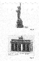
- FIG. 2 shows the image of a three-dimensional structure, which in an arrangement according to FIG. 1 by writing in IP-L and subsequently developing the photosensitive substance.
- an oil objective for the refractive index n ⁇ 1.52 and a photoresist with the refractive index n ⁇ 1.48 was used.
- the template was, as can be seen, the New York Statue of Liberty, which was written in a total size of about 300 microns in the photosensitive substance.
- FIG. 4 again shows the image of a three-dimensional structure, which in an inventively designed arrangement according to FIG. 1 originated.
- the New York Statue of Liberty has also been illuminated here as a three-dimensional structure.
- the Statue of Liberty is in opposite FIG. 2 unchanged high resolution and accordingly high detail much larger; their total height is about 1 mm.
- FIG. 4 it can be understood that three-dimensional structures can be written in the photosensitive substance with the present invention, whose extension in the direction of the optical axis is greater than the working distance of the lens used for writing or exposure. And this, as you can see, with the highest spatial resolution.
- FIG. 5 shows another example of a photolithographically generated three-dimensional structure using the method according to the invention, this structure has a total height of about 200 microns and a despite this total height previously unattainable detail in the spatial resolution.
Landscapes
- Engineering & Computer Science (AREA)
- Chemical & Material Sciences (AREA)
- Physics & Mathematics (AREA)
- Mechanical Engineering (AREA)
- Materials Engineering (AREA)
- Optics & Photonics (AREA)
- Power Engineering (AREA)
- Manufacturing & Machinery (AREA)
- Combustion & Propulsion (AREA)
- General Engineering & Computer Science (AREA)
- General Physics & Mathematics (AREA)
- Spectroscopy & Molecular Physics (AREA)
- Toxicology (AREA)
- Health & Medical Sciences (AREA)
- Microelectronics & Electronic Packaging (AREA)
- Exposure And Positioning Against Photoresist Photosensitive Materials (AREA)
Abstract
Description
Die Erfindung betrifft ein Verfahren zum ortsaufgelösten Einbringen eines Intensitätsmusters aus elektromagnetischer Strahlung in eine photosensitive Substanz mit durch Photoneneinstrahlung veränderbaren Eigenschaften nach dem Oberbegriff des Anspruchs 1 sowie eine Vorrichtung zum Durchführen eines solchen Verfahrens nach dem Oberbegriff des Anspruchs 12. Die vorliegende Erfindung kann insbesondere beim Beschreiben, Löschen und Wiederbeschreiben eines optischen Datenspeichers sowie beim Ausbilden mikro- und nanoska-liger Strukturen Anwendung finden. Auch diese Anwendungen bzw. Verwendungen sind Gegenstand der vorliegenden Erfindung.The invention relates to a method for the spatially resolved introduction of an intensity pattern of electromagnetic radiation into a photosensitive substance with photon radiation variable properties according to the preamble of claim 1 and an apparatus for performing such a method according to the preamble of claim 12. The present invention can be particularly described in the description , Erase and rewrite an optical data storage and find application in the formation of micro- and nano-scale structures. These applications and uses are the subject of the present invention.
Die im Rahmen der vorliegenden Erfindung verwendete photosensitive Substanz besitzt als Ausgangszustand einen ersten, flüssigen Zustand und kann ihre Eigenschaften durch Photoneneinstrahlung in mindestens einen zweiten Zustand verändern. Die Veränderung dieser Eigenschaften erfolgt dadurch, dass elektromagnetische Strahlung mittels eines optischen Abbildungssystems in die Substanz geleitet und dort auf vorbestimmte Ortskoordinaten abgebildet wird, um an diesen Ortskoordinaten bzw. in Bereichen, die diese Ortskoordinaten umgeben, eine Veränderung der Substanzeigenschaften zu erzeugen. Bei der elektromagnetischen Strahlung kann es sich insbesondere, ohne Einschränkung der Allgemeinheit, um einen kollimierten Laserstrahl handeln, der durch das optische Abbildungssystem auf ein beugungsbegrenztes Volumen abgebildet wird, also fokussiert wird. Die Veränderung der Substanzeigenschaften kann dauerhaft sein und beispielsweise in einer Veränderung des flüssigen in einen festen Zustand bestehen; für Anwendungen wie die Speicherung von Daten kann die Veränderung der Substanzeigenschaften jedoch auch nur vorübergehend sein und beispielsweise durch eine thermische Behandlung der Substanz beseitigt werden oder sich von selbst zurückbilden. Auch eine dauerhafte Veränderung kann im Übrigen reversibel oder nicht-reversibel sein.The photosensitive substance used in the context of the present invention has as a starting state a first, liquid state and can change its properties by photon irradiation in at least a second state. The change in these properties takes place in that electromagnetic radiation is guided into the substance by means of an optical imaging system and imaged there on predetermined spatial coordinates in order to produce a change in the substance properties at these spatial coordinates or in regions which surround these spatial coordinates. The electromagnetic radiation may in particular, without limiting the generality, be a collimated laser beam, which is imaged by the optical imaging system on a diffraction-limited volume, that is focused. The change in the substance properties can be permanent and consist, for example, in a change of the liquid to a solid state; however, for applications such as data storage, the change in substance properties may be transient and, for example, temporary be eliminated by a thermal treatment of the substance or regress itself. By the way, a permanent change can also be reversible or non-reversible.
Der erste, flüssige Zustand der verwendeten photosensitiven Substanz ist im Rahmen der vorliegenden Erfindung nicht nur als flüssiger Aggregatzustand im eigentlichen Sinne zu verstehen, also als der Zustand eines Stoffs, in dem dieser einer Formänderung so gut wie keinen bzw. beim dickflüssigen Fluid nur einen geringen, einer Volumenänderung hingegen einen recht großen Widerstand entgegensetzt, sondern die photosensitive Substanz kann in ihrem ersten, flüssigen Zustand auch als Paste, also als Feststoff-Flüssigkeitsgemisch oder Suspension mit einem hohen Gehalt an Feststoffen vorliegen, die gegebenenfalls gar nicht mehr fließfähig, sondern streichfest ist.The first, liquid state of the photosensitive substance used in the context of the present invention is to be understood not only as a liquid state of matter in the strict sense, ie as the state of a substance in which this a shape change as good as none or the viscous fluid only a small , A volume change, however, a very large resistance opposes, but the photosensitive substance may be present in their first, liquid state as a paste, ie as a solid-liquid mixture or suspension with a high content of solids, which may no longer be flowable, but Streichfest ,
Die elektromagnetische Strahlung, die im Rahmen der vorliegenden Erfindung eingesetzt wird, ist im Normalfall Licht im sichtbaren oder infraroten Spektrum. Wenn im folgenden daher zur einfacheren Darstellung bzw. Formulierung von "Lichtstrahl", "Lichteinstrahlung" und "Belichtung" gesprochen wird, ist dies nur beispielhaft zu verstehen und schließt nicht aus, dass im Rahmen der vorliegenden Erfindung gegebenenfalls auch elektromagnetische Strahlung mit anderen Wellenlängen verwendet wird.The electromagnetic radiation used in the present invention is normally light in the visible or infrared spectrum. If, in the following, therefore, the simpler representation or formulation of "light beam", "light irradiation" and "exposure" is spoken, this is to be understood only as an example and does not exclude that in the context of the present invention may also be used electromagnetic radiation with other wavelengths becomes.
Das ortsaufgelöste Einbringen der elektromagnetischen Strahlung erfolgt im Rahmen der vorliegenden Erfindung durch eine optische Abbildung, wodurch die Strahlung als Intensitätsmuster abgebildet, insbesondere fokussiert wird. Wenn im folgenden von "Fokussieren" gesprochen wird, steht dies stellvertretend für das Einbringen von optisch abgebildeten Intensitätsmustern der elektromagnetischen Strahlung in die photosensitive Substanz; denn im Rahmen der vorliegenden Erfindung können auch Abbildungen von anderen Intensitätsmustern in eine Bildebene innerhalb der photosensitiven Substanz zum Einsatz kommen.The spatially resolved introduction of the electromagnetic radiation takes place in the context of the present invention by an optical imaging, whereby the radiation is imaged, in particular focused, as an intensity pattern. In the following, when "focusing" is used, it is representative of the incorporation of optically imaged intensity patterns of the electromagnetic radiation into the photosensitive substance; For in the context of the present invention, also images of other intensity patterns can be used in an image plane within the photosensitive substance.
Ein Verfahren und eine Vorrichtung der vorliegenden Art werden in der Regel zum ortsaufgelösten Belichten (im Folgenden auch: Schreiben) von ein-, zwei- oder dreidimensionalen Strukturen in der photosensitiven Substanz verwendet, um insbesondere Daten mehrdimensional zu speichern oder mehrdimensionale Gegenstände bzw. Strukturen und Masken im Nanometer- und Mikrometerbereich zu erzeugen.A method and a device of the present type are generally used for spatially resolved exposure (hereinafter also: writing) of one-, two- or three-dimensional structures used in the photosensitive substance, in particular to multi-dimensionally store data or to produce multi-dimensional objects or masks and masks in the nanometer and micrometer range.
Im Bereich der Stereolithographie zum Erzeugen von Strukturen im Makrobereich ist beispielsweise in der
Das exakte, ortsaufgelöste Einbringen eines fokussierten Lichtstrahls in eine photosensitive Substanz eignet sich insbesondere dann zur Herstellung einer dreidimensionalen Struktur, wenn die Veränderung der Substanz relativ genau und ausschließlich im Fokus hervorgerufen wird. Denn durch geeignete Abbildungssysteme, beispielsweise Piezobühnen zur Bewegung des Substrats oder strahlablenkende Vorrichtungen, wie Galvanospiegel, Mikrospiegelaktoren, räumliche Modulatoren für Licht oder akusto-optische Deflektoren, kann der Fokus einen recht großen, dreidimensional ausgedehnten Schreibbereich in der photosensitiven Substanz scannen. Dies ist eher nicht für stereolithographische Verfahren, wie sie aus der
Bei einer Veränderung der Ortskoordinaten entlang der optischen Achse des verwendeten optischen Abbildungssystems ergibt sich jedoch, wie überall auf dem Gebiet der abbildenden Optik, das Problem der Abbildungsfehler oder Aberrationen, die mit zunehmender Schreibtiefe, also mit zunehmendem Anteil von Material im optischen Pfad mit nicht optimal abgestimmtem Brechungsindex, zunehmen. Im Stand der Technik können daher nur dreidimensionale Strukturen mit sehr begrenzter Höhe erzeugt werden.However, with a change in the position coordinates along the optical axis of the optical imaging system used, as in the field of imaging optics, the problem of aberrations or aberrations becomes less optimal with increasing writing depth, ie with an increasing proportion of material in the optical path matched refractive index, increase. In the prior art, therefore, only three-dimensional structures can be produced with a very limited height.
Auf dem Gebiet der Zwei- und Mehrphotonenabsorbtionslithographie ist bereits ein Verfahren bekannt, das das Problem der Abbildungsfehler durch Ausnutzen einer Vorkompensation statisch auszugleichen versucht. In der Publikation
Ausgehend von diesem Stand der Technik liegt der vorliegenden Erfindung die Aufgabe zugrunde, bei einem Verfahren und einer Vorrichtung der vorliegenden Art Abbildungsfehler weitgehend zu vermeiden oder im Wesentlichen entlang der optischen Achse des Abbildungssystems konstant zu halten.Based on this prior art, the present invention has the object, in a method and a device of the present type largely to avoid aberrations or to keep substantially constant along the optical axis of the imaging system.
Gelöst ist diese Aufgabe durch ein Verfahren mit den Merkmalen des Anspruchs 1 sowie durch eine Vorrichtung mit den Merkmalen des Anspruchs 12.This object is achieved by a method having the features of claim 1 and by an apparatus having the features of claim 12.
Vorteilhafte Weiterbildungen des erfindungsgemäßen Verfahrens finden sich in den Ansprüchen 2 bis 9; bevorzugte Ausgestaltungen der erfindungsgemäßen Vorrichtung sind in den Ansprüchen 13 bis 16 niedergelegt. Bevorzugte Anwendungen des erfindungsgemäßen Verfahrens finden sich in den Ansprüchen 10 und 11; eine bevorzugte Verwendung der erfindungsgemäßen Vorrichtung ist Gegenstand des Anspruchs 17.Advantageous developments of the method according to the invention can be found in
Erfindungsgemäß wird die gegebene Aufgabe dadurch gelöst, dass das Objektiv des optischen Abbildungssystems bzw. eine Oberfläche einer Objektivlinse, durch die die elektromagnetische Strahlung, insbesondere ein Lichtstrahl, aus dem optischen Abbildungssystem austritt, in die flüssige photosensitive Substanz eingetaucht wird, in der die Veränderung der Substanzeigenschaften erzeugt werden soll. Die photosensitive Substanz fungiert demnach als Immersionssystem, so dass durch Verwenden von geeigneten Immersionsobjektiven die Abbildungsfehler nahezu oder gar vollständig eliminiert werden können. Selbst bei nicht ideal angepassten Brechungsindizes von Objektivlinse und photosensitiver Substanz führt die Erfindung zu sehr viel besseren Ergebnissen als bisher, denn auch dann sind die Aberrationen unabhängig von der Schreibtiefe konstant und die Abbildung im gesamten Schreibbereich identisch.According to the invention this object is achieved in that the objective of the optical imaging system or a surface of an objective lens, through which the electromagnetic radiation, in particular a light beam, exits the optical imaging system is immersed in the liquid photosensitive substance, in which the change of Substance properties should be generated. The photosensitive substance thus acts as an immersion system, so that by using suitable immersion objectives, the aberrations can be almost or completely eliminated. Even with not ideally matched refractive indices of objective lens and photosensitive substance, the invention leads to much better results than before, because even then the aberrations are independent of the writing depth constant and the image in the entire writing area identical.
Ein Hauptgrund für diese erfindungsgemäßen Effekte besteht darin, dass die im Stand der Technik stets vorhandene(n) Grenzfläche(n) zwischen der photosensitiven Substanz und dem Objektiv des optischen Abbildungssystems im Wesentlichen entfällt (entfallen). Denn eine solche Grenzfläche (solche Grenzflächen) führt (führen) grundsätzlich zu Abbildungsfehlern.A main reason for these effects according to the invention is that the interface (s) always present in the prior art between the photosensitive substance and the objective of the optical imaging system is substantially eliminated (eliminated). Because such an interface (such interfaces) leads (lead) in principle to aberrations.
Mit dem erfindungsgemäßen Verfahren werden also Abweichungen von einer idealen optischen Abbildung vermieden, indem die photosensitive Substanz gleichzeitig als Immersionsmittel dient, wobei ein Signal, also der Fokus oder ein sonstiges Intensitätsmuster der über das optische Abbildungssystem eingestrahlten elektromagnetischen Strahlung, wie beispielsweise eines Lichtstrahls, so auf einen Schreibbereich innerhalb der photosensitiven Substanz abgebildet wird, dass der Abstand zwischen der Objektivlinse und den Bildebenen der Signale im Schreibbereich einen konstanten Wert annimmt. Aberrationen aufgrund einer Brechungsindexfehlanpassung des optischen Systems bleiben entlang der optischen Achse konstant (und sind im Idealfall konstant Null), und die photosensitive Substanz kann im gesamten Schreibbereich mit identischen Foki bzw. Intensitätsmustern belichtet werden.Deviations from an ideal optical image are therefore avoided with the method according to the invention in that the photosensitive substance simultaneously serves as immersion medium, with a signal, ie the focus or another intensity pattern of the electromagnetic radiation irradiated via the optical imaging system, such as a light beam, for example imaging a write area within the photosensitive substance, the distance between the objective lens and the image planes of the signals in the write area becomes constant. Aberrations due to refractive index mismatch of the optical system remain constant along the optical axis (and ideally are constant zero), and the photosensitive substance can be exposed to identical focal intensity patterns throughout the write area.
Ein weiterer, großer Vorteil der vorliegenden Erfindung besteht im Übrigen darin, dass die Ausdehnung der abbildbaren Ortskoordinaten in Richtung der optischen Achse des Abbildungssystems nicht mehr durch den Arbeitsabstand des Objektivs begrenzt ist. Denn das Objektiv taucht erfindungsgemäß beim Abbilden, insbesondere Fokussieren des Lichtstrahls auf die vorbestimmten Ortskoordinaten direkt in die photosensitive Substanz ein. Es können damit dreidimensionale Strukturen in die photosensitive Substanz geschrieben werden, deren Ausdehnung in Richtung der optischen Achse sehr viel größer ist und die somit sehr viel höher als die im Stand der Technik herstellbaren Strukturen sind, und zwar unter potentieller Beibehaltung höchster räumlicher Auflösung..Incidentally, another great advantage of the present invention consists in the fact that the extent of the imageable location coordinates in the direction of the optical axis of the imaging system is no longer limited by the working distance of the objective. Because the lens emerges according to the invention when imaging, in particular focusing the light beam on the predetermined location coordinates directly into the photosensitive substance. It can thus be written in the photosensitive substance three-dimensional structures whose extension in the direction of the optical axis is much larger and which are thus much higher than the manufacturable in the prior art structures, while retaining the highest spatial resolution ..
Das erfindungsgemäße Verfahren und die entsprechende Vorrichtung werden bevorzugt dazu benutzt, ein-, zwei- und/oder dreidimensionale Strukturen in einem Schreibbereich innerhalb der photosensitiven Substanz zu erzeugen.The method and the corresponding apparatus according to the invention are preferably used to produce one-, two- and / or three-dimensional structures in a writing area within the photosensitive substance.
In einer bevorzugten Variante des neuen Verfahrens besteht das Schreibsignal bzw. bestehen die Schreibsignale (mehrere Signale können zum Beispiel im Falle der oben anhand der
Mit der vorliegenden Erfindung kann ein optisches System dazu verwendet werden, mit konstanten Aberrationen oder ohne Aberrationen optische Datenspeicher mit besonders wenigen Abbildungsfehlern herzustellen. Durch Auswahl einer geeigneten photosensitiven Substanz kann ein solcher optischer Datenspeicher beschrieben, gelöscht und wiederbeschrieben werden.With the present invention, an optical system can be used to produce with constant aberrations or without aberrations optical data storage with very few aberrations. By selecting a suitable photosensitive substance, such an optical data memory can be described, deleted and rewritten.
Ebenso können Mikro- und Nanostrukturen mit ansonsten unerreichbarer Präzision über den gesamten Schreibbereich innerhalb einer photosensitiven Substanz hergestellt werden.Likewise, micro and nanostructures of otherwise unattainable precision can be made throughout the writing area within a photosensitive substance.
Durch einen schichtweisen Aufbau der in der photosensitiven Substanz zu erzeugenden ein-, zwei- und/oder dreidimensionalen Struktur kann vermieden werden, durch bereits vorstrukturiertes Material zu belichten bzw. zu schreiben. Denn in aller Regel ändert sich der Brechungsindex der photosensitiven Substanz, wenn sich diese aufgrund der Photoneneinstrahlung verändert. Dies kann zu weiteren Abbildungsfehlern führen, wenn der Lichtstrahl durch verändertes Material hindurch in die photosensitive Substanz fokussiert bzw. abgebildet wird.By a layered structure of the one, two and / or three-dimensional structure to be produced in the photosensitive substance, it is possible to avoid exposing or writing through pre-structured material. As a rule, the refractive index of the photosensitive substance changes when it changes due to the photon radiation. This can lead to further aberrations when the light beam is focused through altered material into the photosensitive substance or imaged.
Vorzugsweise wird die flüssige photosensitive Substanz auf einen als Substrat verwendeten Festkörper, beispielsweise eine Glasplatte oder einen sonstigen, beliebig geformten, gegebenenfalls auch opaken Körper, aufgebracht und dann das optische Abbildungssystem in die flüssige photosensitive Substanz eingetaucht. Das Substrat befindet sich damit nicht zwischen der photosensitiven Substanz und dem optischen Abbildungssystem, so dass insofern weitere Abbildungsfehler durch Grenzflächen vermieden werden und die Höhe der zu schreibenden Strukturen nicht durch den Arbeitsabstand des Objektivs des Abbildungssystems begrenzt wird.Preferably, the liquid photosensitive substance is applied to a solid body used as a substrate, for example a glass plate or other, arbitrarily shaped, optionally also opaque body, and then immersed the optical imaging system in the liquid photosensitive substance. The substrate is thus not located between the photosensitive substance and the optical imaging system, so that in this respect further aberrations are avoided by interfaces and the height of the writing Structures is not limited by the working distance of the lens of the imaging system.
Nach einer Weiterbildung dieser Variante der Erfindung wird ein transparenter, scheiben- oder plattenförmiger Festkörper als Substrat verwendet, der beidseitig eine flüssige photosensitive Substanz trägt. Auf der dem optischen Abbildungssystem zugewandten Seite des Substrats dient die photosensitive Substanz dann erfindungsgemäß als Immersionsmittel, wobei der Lichtstrahl nicht nur in diese gleichzeitig als Immersionsmittel fungierende photosensitive Substanz fokussiert werden kann, sondern bedarfsweise auch durch diese Substanz und das Substrat hindurch in die auf der abgewandten Seite auf das Substrat aufgebrachte photosensitive Substanz. Die Ausrichtung von Strukturen auf beiden Substratseiten ist erfindungsgemäß sehr viel genauer möglich als im bisherigen Stand der Technik, da in einem Schritt direkt auf beiden Substratseiten strukturiert werden kann. Das Drehen und Ausrichten des Substrates wie nach Stand der Technik erforderlich entfällt.According to a development of this variant of the invention, a transparent, disk-shaped or plate-shaped solid body is used as the substrate which carries a liquid photosensitive substance on both sides. On the side of the substrate facing the optical imaging system, the photosensitive substance then serves as immersion agent, whereby the light beam can be focused not only into these simultaneously acting as immersion photosensitive substance, but also, if necessary, through this substance and the substrate into the on the remote Side applied to the substrate photosensitive substance. The alignment of structures on both sides of the substrate according to the invention is much more possible than in the prior art, as can be structured in one step directly on both sides of the substrate. The rotation and alignment of the substrate as required by the prior art is eliminated.
Als Strahlungsquelle für die elektromagnetische Strahlung bzw. als Lichtquelle wird für die vorliegende Erfindung vorzugsweise ein Laser, insbesondere ein Dauerstrichlaser oder gepulster Laser im elektromagnetischen Spektrum von UV, sichtbarem Licht oder nahinfrarot verwendet. Die flüssige photosensitive Substanz kann im Rahmen der vorliegenden Erfindung durch Photoneneinstrahlung auf physikalischem, thermischem und/oder chemischem Wege lokal verändert werden.As a radiation source for the electromagnetic radiation or as a light source for the present invention preferably a laser, in particular a continuous wave laser or pulsed laser in the electromagnetic spectrum of UV, visible light or near-infrared is used. In the context of the present invention, the liquid photosensitive substance can be locally modified by photon irradiation by physical, thermal and / or chemical means.
Die Veränderung der Substanzeigenschaften der photosensitiven Substanz können, wie an sich im Stand der Technik bekannt, durch einen Einphotonenprozess oder einen Mehrphotonenprozess initiiert und/oder abgeregt werden.The change in the substance properties of the photosensitive substance may be initiated and / or de-excited as known in the art by a one-photon process or a multiphoton process.
Wie bereits erwähnt, können die erfindungsgemäße Vorrichtung und das Verfahren insbesondere und vorteilhaft zum Beschreiben und/oder Löschen von Datenspeichern sowie zum Erzeugen mikro- oder nanoskaliger Strukturen verwendet werden. In letzterem Fall können die durch Photonenabsorbtion veränderten Punkte oder Bereiche der photosensitiven Substanz anschließend durch einen selektiven Entwicklungsprozess freigelegt oder auch entfernt werden.As already mentioned, the device according to the invention and the method can be used in particular and advantageously for writing and / or erasing data memories as well as for generating micro- or nanoscale structures. In the latter case, those altered by photon absorption Dots or areas of the photosensitive substance are subsequently exposed or removed by a selective development process.
Die vorliegende Erfindung basiert auf der Erkenntnis, dass das in die photosensitive Substanz abgebildete Intensitätsmuster der elektromagnetischen Strahlung, insbesondere ein Lichtstrahl-Fokus, mit zunehmender Schreibtiefe, also zunehmender Eindringtiefe in die brechzahlfehlangepasste photosensitive Substanz entlang der optischen Achse des Abbildungssystems Abbildungsfehler aufsammelt und damit eine genaue Ortsauflösung nicht mehr zulässt. Die Abbildungsfehler sind umso stärker, je unterschiedlicher die Brechungsindizes zwischen der photosensitiven Substanz und der Luft bzw. einem Substrat sind, wenn durch ein solches hindurch eingestrahlt wird. Die Abbildungsfehler werden erfindungsgemäß nicht unbedingt beseitigt, sondern innerhalb eines Schreibbereichs entlang der optischen Achse des Abbildungssystems lediglich konstant oder zumindest im Wesentlichen konstant gehalten, so dass eine hochgenaue Ortsauflösung innerhalb der photosensitiven Substanz erzielt werden kann.The present invention is based on the finding that the intensity pattern of the electromagnetic radiation, in particular a light beam focus imaged in the photosensitive substance, picks up aberrations with increasing writing depth, thus increasing depth of penetration into the refractive index mismatched photosensitive substance along the optical axis of the imaging system and thus an accurate Spatial resolution no longer allows. The aberrations are the stronger, the more different the refractive indices between the photosensitive substance and the air or a substrate when it is irradiated through one. The aberrations are not necessarily eliminated according to the invention, but kept within a writing area along the optical axis of the imaging system only constant or at least substantially constant, so that a highly accurate spatial resolution within the photosensitive substance can be achieved.
Ein Ausführungsbeispiel für eine erfindungsgemäße Vorrichtung sowie Versuchsergebnisse für ein erfindungsgemäß durchgeführtes Verfahren werden im Folgenden anhand der beigefügten Zeichnungen näher beschrieben und erläutert. Es zeigen:
- Figur 1
- eine schematische Darstellung einer Anordnung von erfindungswesentlichen Vorrichtungsteilen;
Figur 2- eine Abbildung einer mit dem erfindungsgemäßen Verfahren hergestellten dreidimensionalen Mikrostruktur;
Figur 3- eine Abbildung einer nach dem Stand der Technik hergestellten dreidimensionalen Mikrostruktur nach derselben
Vorlage wie Figur 3 ; - Figur 4
- eine weitere Abbildung einer mit dem erfindungsgemäßen Verfahren hergestellten Mikrostruktur;
Figur 5- eine weitere Abbildung einer mit dem erfindungsgemäßen Verfahren hergestellten Mikrostruktur.
- FIG. 1
- a schematic representation of an arrangement of essential to the invention device parts;
- FIG. 2
- an illustration of a three-dimensional microstructure produced by the method according to the invention;
- FIG. 3
- an illustration of a prepared according to the prior art three-dimensional microstructure according to the same template as
FIG. 3 ; - FIG. 4
- a further illustration of a microstructure produced by the method according to the invention;
- FIG. 5
- a further illustration of a microstructure produced by the method according to the invention.
Das Objektiv 3 ist ein Immersionsobjektiv; solche Objektive werden typischerweise für die Brechzahlen von Ölen (n~1.5 - 1.7), Glyzerin (n~1.47) oder Wasser (n~1.3) hergestellt. Passt man in dieser Konfiguration das Objektiv an den Brechungsindex des Photolacks 2 an, so kann man prinzipiell die Bildebene 8 entlang der optischen Achse 7 verschieben und mit konstanten Aberrationen abbilden und strukturieren. Die Abbildung kann insbesondere ein Gauss'scher Fokus sein. Im normalen Fall eines kleinen Unterschieds zwischen dem Brechungsindex, für den das Objektiv 3 ideal funktioniert, und dem Brechungsindex der photosensitiven Substanz 2, kann zwar nicht ohne Aberrationsfehler strukturiert werden, jedoch ist dieser Fehler über die gesamte Schreibtiefe entlang einer optischen Achse 7 konstant, was selbst bei einem nicht perfekt angepassten System zu erheblichen Verbesserungen der Schreibqualität gegenüber dem Stand der Technik führt. Dies wird anhand der nachfolgend beschriebenen
Auch bei der Struktur, die in
Claims (17)
wobei die elektromagnetische Strahlung (4) über das optische Abbildungssystem (3) in die photosensitive Substanz (2) geleitet und dort auf vorbestimmte Ortskoordinaten abgebildet wird, um an diesen Ortskoordinaten oder in diese umgebenden Bereichen eine Veränderung der Substanzeigenschaften zu erzeugen,
dadurch gekennzeichnet,
dass eine Oberfläche (6) einer Objektivlinse des optischen Abbildungssystems (3), durch die die elektromagnetische Strahlung (4) aus diesem austritt,
in die flüssige photosensitive Substanz (2) eingetaucht wird.Method for the spatially resolved introduction of an electromagnetic radiation intensity pattern by means of an optical imaging system into a photosensitive substance with photon radiation-variable properties comprising a first, liquid and at least one second state,
wherein the electromagnetic radiation (4) is guided into the photosensitive substance (2) via the optical imaging system (3) and imaged there on predetermined spatial coordinates in order to produce a change in the substance properties at these spatial coordinates or in surrounding areas,
characterized,
in that a surface (6) of an objective lens of the optical imaging system (3) through which the electromagnetic radiation (4) emerges therefrom,
is immersed in the liquid photosensitive substance (2).
dadurch gekennzeichnet,
dass mit dem abgebildeten Intensitätsmuster der elektromagnetischen Strahlung (4) ein-, zwei- und/oder dreidimensionale Strukturen in die photosensitive Substanz (2) geschrieben werden.Method according to claim 1
characterized,
that with the depicted intensity pattern of the electromagnetic radiation (4) mono-, di- and / or three-dimensional structures in the photosensitive substance (2) are written.
dadurch gekennzeichnet,
dass die ein-, zwei- und/oder dreidimensionalen Strukturen mit mehreren abgebildeten Intensitätsmustern sequentiell oder gleichzeitig geschrieben werden und hierfür ein oder mehrere optische Abbildungssysteme verwendet werden.Method according to claim 2,
characterized,
that the one-, two- and / or three-dimensional structures having a plurality of imaged intensity patterns are written sequentially or simultaneously, and one or a plurality of optical imaging systems are used for this purpose.
dadurch gekennzeichnet,
dass die flüssige photosensitive Substanz (2) auf einen als Substrat (1) verwendeten Festkörper aufgebracht und dann das optische Abbildungssystem (3) in die flüssige photosensitive Substanz (2) eingetaucht wird.Method according to at least one of claims 1 to 3,
characterized,
in that the liquid photosensitive substance (2) is applied to a solid used as substrate (1) and then the optical imaging system (3) is immersed in the liquid photosensitive substance (2).
dadurch gekennzeichnet,
dass ein transparenter, scheiben- oder plattenförmiger Festkörper als Substrat (1) verwendet und beidseitig eine flüssige photosensitive Substanz (2) auf das Substrat (1) aufgebracht wird.Method according to claim 4,
characterized,
that a transparent, disc-shaped or plate-shaped solid body used as the substrate (1) and on both sides of a liquid photo-sensitive substance (2) onto the substrate (1) is applied.
dadurch gekennzeichnet,
dass als Quelle für die elektromagnetische Strahlung (4) ein Laser, insbesondere ein Dauerstrichlaser oder gepulster Laser im elektromagnetischen Spektrum von UV, sichtbarem Licht oder Nahinfrarot verwendet wird.Method according to at least one of claims 1 to 5,
characterized,
in that a laser, in particular a continuous wave laser or pulsed laser in the electromagnetic spectrum of UV, visible light or near-infrared is used as the source for the electromagnetic radiation (4).
dadurch gekennzeichnet,
dass das Abbilden des Intensitätsmusters durch Fokussieren der elektromagnetischen Strahlung auf die vorbestimmten Ortskoordinaten erfolgt.Method according to at least one of claims 1 to 6,
characterized,
in that the imaging of the intensity pattern is effected by focusing the electromagnetic radiation on the predetermined location coordinates.
dadurch gekennzeichnet,
dass die flüssige photosensitive Substanz (2) durch Photoneneinstrahlung auf physikalischem, thermischem und/oder chemischem Wege lokal verändert wird.Method according to at least one of claims 1 to 7,
characterized,
that the liquid photo-sensitive substance (2) is locally changed by photon irradiation on physical, thermal and / or chemical means.
dadurch gekennzeichnet,
dass die Veränderung der Eigenschaften der photosensitiven Substanz (2) durch einen Einphotonenprozess oder einen Mehrphotonenprozess initiiert und/oder abgeregt wird.Method according to at least one of claims 1 to 8;
characterized,
in that the change in the properties of the photosensitive substance (2) is initiated and / or depleted by a one-photon process or a multiphoton process.
zum Erzeugen mikro- oder nanoskaliger Strukturen.Use of a method according to at least one of claims 1 to 9
for generating micro- or nanoscale structures.
dadurch gekennzeichnet,
dass die durch Photoneneinstrahlung veränderten Punkte oder Bereiche der photosensitiven Substanz (2) anschließend durch einen selektiven Entwicklungsprozess freigelegt oder entfernt werden.Application according to claim 10,
characterized,
that the changed by photon irradiation points or areas of the photosensitive substance (2) is then exposed by a selective development process or removed.
dadurch gekennzeichnet,
dass die Vorrichtung so ausgestaltet ist, dass eine Oberfläche (6) einer Objektivlinse des optischen Abbildungssystems (3), durch die die elektromagnetische Strahlung (4) aus diesem austritt, zum Einbringen der elektromagnetischen Strahlung (4) in die photosensitive Substanz (2) in diese eingetaucht wird.Device for the spatially resolved introduction of an intensity pattern of electromagnetic radiation into a photosensitive substance (2) with properties modifiable by photon radiation, comprising a photosensitive substance (2) whose properties can be changed by photon radiation between a first, liquid and at least one second state, and a radiation source and an optical imaging system (3) for introducing an electromagnetic radiation (4) originating from the radiation source into the photosensitive substance (2) and for mapping the electromagnetic radiation (4) in the photosensitive substance (2) to predetermined spatial coordinates (5) create a change in the substance properties at these location coordinates or in those surrounding areas,
characterized,
in that the device is designed in such a way that a surface (6) of an objective lens of the optical imaging system (3), through which the electromagnetic radiation (4) emerges therefrom, for introducing the electromagnetic Radiation (4) in the photosensitive substance (2) is immersed in this.
dadurch gekennzeichnet,
dass mehrere optische Abbildungssysteme (3) vorhanden sind, um mehrere Intensitätsmuster (4) in die photosensitive Substanz (2) abzubilden.Device according to claim 12,
characterized,
in that a plurality of optical imaging systems (3) are present in order to image a plurality of intensity patterns (4) into the photosensitive substance (2).
dadurch gekennzeichnet,
dass die photosensitive Substanz (2) auf einem als Substrat (1) verwendeten Festkörper aufgebracht ist.Device according to one of claims 12 or 13,
characterized,
in that the photosensitive substance (2) is applied to a solid used as substrate (1).
dadurch gekennzeichnet,
dass die photosensitive Substanz (2) beidseitig auf einem als Substrat (1) verwendeten, scheiben- oder plattenförmigen, transparenten Festkörper aufgebracht ist.Device according to claim 14,
characterized,
in that the photosensitive substance (2) is applied on both sides to a disk-shaped or plate-shaped transparent solid used as substrate (1).
dadurch gekennzeichnet,
dass die Strahlungsquelle für die elektromagnetische Strahlung ein Laser, insbesondere ein Dauerstrichlaser oder gepulster Laser im elektromagnetischen Spektrum von UV, sichtbarem Licht oder Nah-Infrarot ist.Device according to at least one of claims 13 to 15,
characterized,
that the radiation source for the electromagnetic radiation is a laser, in particular a continuous wave laser or pulsed laser in the electromagnetic spectrum of UV, visible light or near-infrared is.
Applications Claiming Priority (1)
| Application Number | Priority Date | Filing Date | Title |
|---|---|---|---|
| DE102011012484A DE102011012484A1 (en) | 2011-02-25 | 2011-02-25 | Method and device for the spatially resolved introduction of an intensity pattern of electromagnetic radiation into a photosensitive substance and use thereof |
Publications (1)
| Publication Number | Publication Date |
|---|---|
| EP2492085A1 true EP2492085A1 (en) | 2012-08-29 |
Family
ID=45655724
Family Applications (1)
| Application Number | Title | Priority Date | Filing Date |
|---|---|---|---|
| EP12155363A Withdrawn EP2492085A1 (en) | 2011-02-25 | 2012-02-14 | Method and device for location-triggered application of an intensity pattern from electromagnetic radiation to a photosensitive substance and applications of same |
Country Status (4)
| Country | Link |
|---|---|
| US (1) | US9302430B2 (en) |
| EP (1) | EP2492085A1 (en) |
| CN (1) | CN102649314B (en) |
| DE (2) | DE202011111072U1 (en) |
Cited By (1)
| Publication number | Priority date | Publication date | Assignee | Title |
|---|---|---|---|---|
| WO2017059960A1 (en) * | 2015-10-07 | 2017-04-13 | Baden-Württemberg Stiftung Ggmbh | Method and device for producing microstructures on optical fibres |
Families Citing this family (18)
| Publication number | Priority date | Publication date | Assignee | Title |
|---|---|---|---|---|
| EP3432049A3 (en) | 2013-12-06 | 2019-04-03 | 3M Innovative Properties Co. | Semi-submersible microscope objective and use of the same in multiphoton imaging method |
| EP3077421B1 (en) | 2013-12-06 | 2018-01-31 | 3M Innovative Properties Company | Liquid photoreactive composition and method of fabricating structures |
| DE102015003652B4 (en) * | 2015-03-20 | 2017-03-16 | Universität Stuttgart | A method of connecting a solid-state optical fiber to another optical fiber and solid-state optical fiber to a jointing device |
| DE102015004151B4 (en) * | 2015-03-31 | 2022-01-27 | Feinmetall Gmbh | Method for manufacturing a spring contact pin arrangement with several spring contact pins |
| LT3266594T (en) | 2016-07-07 | 2020-05-25 | Technische Universität Wien | Method and apparatus for lithography-based generative production of three-dimensional articles |
| DE102016014229A1 (en) | 2016-11-30 | 2018-05-30 | Giesecke+Devrient Currency Technology Gmbh | Production method for printing plates for intaglio printing and printing plate for intaglio printing |
| US10413167B2 (en) | 2017-05-30 | 2019-09-17 | Synaptive Medical (Barbados) Inc. | Micro-optical surgical probes and micro-optical probe tips and methods of manufacture therefor |
| US20210088728A1 (en) | 2018-02-23 | 2021-03-25 | Commscope Technologies Llc | 3d printed fiber optic connector end face and method of manufacture |
| DE102018128418B3 (en) * | 2018-11-13 | 2019-11-14 | Nanoscribe Gmbh | Use of a dispenser attachment and dispenser attachment for a device for writing 3D structures by means of laser lithography |
| DE102018221670A1 (en) | 2018-12-13 | 2020-06-18 | Karlsruher Institut für Technologie | Device and method for the optical characterization or processing of an object |
| EP3670440A1 (en) | 2018-12-21 | 2020-06-24 | Rolex Sa | Method for manufacturing a clock component |
| EP3670441A1 (en) | 2018-12-21 | 2020-06-24 | Rolex Sa | Method for manufacturing a clock component |
| US11484969B2 (en) | 2019-10-18 | 2022-11-01 | 3M Innovative Properties Company | Method of making a three-dimensional structure containing substructures |
| CN114746250A (en) | 2019-12-05 | 2022-07-12 | 3M创新有限公司 | Multiphoton imaging method and article in scattering and/or absorbing media |
| CN113895033B (en) * | 2020-06-22 | 2023-04-07 | 上海普利生机电科技有限公司 | Photocuring type 3D printing device and printing method |
| DE102022106696A1 (en) | 2021-03-22 | 2022-09-22 | Polydiagnost Entwicklungs-, Produktions-, Vertriebs-, Und Servicegesellschaft Für Medizinelektronische Diagnostik- Und Therapiegeräte Mbh | Endoscope optics and endoscope |
| DE102021131132A1 (en) | 2021-11-26 | 2023-06-01 | Universität Stuttgart, Körperschaft Des Öffentlichen Rechts | Lens protector as a disposable item to protect lenses |
| DE102022111789B3 (en) | 2022-05-11 | 2023-02-23 | Nanoscribe Holding Gmbh | Method and device for producing a three-dimensional structure in a lithography fluid |
Citations (5)
| Publication number | Priority date | Publication date | Assignee | Title |
|---|---|---|---|---|
| WO1990006540A1 (en) * | 1988-12-05 | 1990-06-14 | Centre National De La Recherche Scientifique (Cnrs) | Process and device for the manufacture of a solid three-dimensional part by the phototransformation of an organic liquid |
| WO1992000185A1 (en) * | 1990-06-22 | 1992-01-09 | Martin Russell Harris | Optical waveguides |
| DE10111422A1 (en) | 2001-03-09 | 2002-09-26 | Hannover Laser Zentrum | Photosensitive molding production by irradiating a liquid material in a bath, to solidify the material, using a multi-photon absorption process |
| EP1616344B1 (en) | 2003-04-13 | 2008-08-13 | Max-Planck-Gesellschaft zur Förderung der Wissenschaften e.V. | Creation of a permanent structure with high three-dimensional resolution |
| WO2011141521A1 (en) * | 2010-05-11 | 2011-11-17 | Fraunhofer-Gesellschaft zur Förderung der angewandten Forschung e.V. | Device and method for producing three-dimensional structures |
Family Cites Families (8)
| Publication number | Priority date | Publication date | Assignee | Title |
|---|---|---|---|---|
| US6214276B1 (en) * | 1999-05-18 | 2001-04-10 | Creo Srl | Method of forming objects from thermosensitive composition |
| EP1292852B1 (en) * | 2000-06-15 | 2005-11-09 | 3M Innovative Properties Company | Microfabrication of organic optical elements |
| US7700267B2 (en) * | 2003-08-11 | 2010-04-20 | Taiwan Semiconductor Manufacturing Company, Ltd. | Immersion fluid for immersion lithography, and method of performing immersion lithography |
| WO2006109355A1 (en) * | 2005-04-11 | 2006-10-19 | Japan Science And Technology Agency | Multiple-beam microstructure laser lithographic method and device employing laser beams of different wavelength |
| US7816069B2 (en) * | 2006-06-23 | 2010-10-19 | International Business Machines Corporation | Graded spin-on organic antireflective coating for photolithography |
| GB0619041D0 (en) * | 2006-09-27 | 2006-11-08 | Imec Inter Uni Micro Electr | Watermark defect reduction by resist optimisation |
| JP5234315B2 (en) * | 2007-12-03 | 2013-07-10 | ソニー株式会社 | Stereolithography apparatus and stereolithography method |
| US20100039628A1 (en) * | 2008-03-19 | 2010-02-18 | Nikon Corporation | Cleaning tool, cleaning method, and device fabricating method |
-
2011
- 2011-02-25 DE DE202011111072.2U patent/DE202011111072U1/en not_active Expired - Lifetime
- 2011-02-25 DE DE102011012484A patent/DE102011012484A1/en active Pending
-
2012
- 2012-02-14 EP EP12155363A patent/EP2492085A1/en not_active Withdrawn
- 2012-02-23 CN CN201210044761.8A patent/CN102649314B/en active Active
- 2012-02-27 US US13/405,616 patent/US9302430B2/en active Active
Patent Citations (5)
| Publication number | Priority date | Publication date | Assignee | Title |
|---|---|---|---|---|
| WO1990006540A1 (en) * | 1988-12-05 | 1990-06-14 | Centre National De La Recherche Scientifique (Cnrs) | Process and device for the manufacture of a solid three-dimensional part by the phototransformation of an organic liquid |
| WO1992000185A1 (en) * | 1990-06-22 | 1992-01-09 | Martin Russell Harris | Optical waveguides |
| DE10111422A1 (en) | 2001-03-09 | 2002-09-26 | Hannover Laser Zentrum | Photosensitive molding production by irradiating a liquid material in a bath, to solidify the material, using a multi-photon absorption process |
| EP1616344B1 (en) | 2003-04-13 | 2008-08-13 | Max-Planck-Gesellschaft zur Förderung der Wissenschaften e.V. | Creation of a permanent structure with high three-dimensional resolution |
| WO2011141521A1 (en) * | 2010-05-11 | 2011-11-17 | Fraunhofer-Gesellschaft zur Förderung der angewandten Forschung e.V. | Device and method for producing three-dimensional structures |
Non-Patent Citations (1)
| Title |
|---|
| APPLIED OPTICS, vol. 27, no. 26, 1998 |
Cited By (2)
| Publication number | Priority date | Publication date | Assignee | Title |
|---|---|---|---|---|
| WO2017059960A1 (en) * | 2015-10-07 | 2017-04-13 | Baden-Württemberg Stiftung Ggmbh | Method and device for producing microstructures on optical fibres |
| US10870243B2 (en) | 2015-10-07 | 2020-12-22 | Baden-Württemberg Stiftung Ggmbh | Method and device for producing microstructures on optical fibers |
Also Published As
| Publication number | Publication date |
|---|---|
| CN102649314A (en) | 2012-08-29 |
| DE202011111072U1 (en) | 2019-03-27 |
| CN102649314B (en) | 2016-01-20 |
| US20120218535A1 (en) | 2012-08-30 |
| DE102011012484A1 (en) | 2012-08-30 |
| US9302430B2 (en) | 2016-04-05 |
Similar Documents
| Publication | Publication Date | Title |
|---|---|---|
| EP2492085A1 (en) | Method and device for location-triggered application of an intensity pattern from electromagnetic radiation to a photosensitive substance and applications of same | |
| EP4032688B1 (en) | Method and device for producing a three-dimensional object in an optically reactive starting material | |
| DE102016214606B3 (en) | Method and device for the lithographic production of a target structure at a non-planar starting structure | |
| DE102015012980B4 (en) | Process for producing microstructures on optical fibers | |
| DE102013215040B4 (en) | Compact apparatus for producing a three-dimensional object by solidifying a photo-hardening material | |
| EP3459758B1 (en) | Method for producing a valuable document and printing device | |
| DE10116059B4 (en) | Moving lens lithograph and method of making digital holograms in a storage medium | |
| EP3266594A1 (en) | Method and apparatus for lithography-based generative production of three-dimensional articles | |
| DE102014225197A1 (en) | Method for changing a surface shape, reflective optical element, projection objective and EUV lithography system | |
| DE60215897T2 (en) | Internally marked quartz glass and marking process | |
| EP3162549A1 (en) | Method and device for forming an optical element with at least one functional area, and use of the device | |
| DE102018128418B3 (en) | Use of a dispenser attachment and dispenser attachment for a device for writing 3D structures by means of laser lithography | |
| DE102014220168B4 (en) | Optical system for lithographic structure generation and method for the determination of relative coordinates | |
| DE102012212194B4 (en) | Microlithographic projection exposure apparatus and method for modifying an optical wavefront in a catoptric objective of such a system | |
| DE102014215439B4 (en) | Method for producing a structure | |
| DE102011076658A1 (en) | Illumination lens for use in projection illumination system for extreme UV-projection lithography for manufacturing e.g. semiconductor chip, has first selection facet comprising larger surface than surfaces of second and third facets | |
| DE102008043324B4 (en) | Optical arrangement for the three-dimensional structuring of a material layer | |
| DE102008006438B4 (en) | Method and device for structuring a radiation-sensitive material | |
| DE102011017329A1 (en) | Method for producing an optical waveguide in a polymer | |
| EP3894928A2 (en) | Apparatus and method for optically characterizing or processing an object, and object transport unit | |
| DE102016218744A1 (en) | Projection exposure system with liquid layer for wave front correction | |
| DE102022127259A1 (en) | Method and device for imaging a beam onto an object and method for making an opening in a workpiece by means of this method | |
| DE102020204426A1 (en) | Method and device for manipulating the surface shape of an optical element | |
| DE102019131327A1 (en) | Device and method for measuring substrates for semiconductor lithography | |
| DE102009033823A1 (en) | Semiconductor component i.e. computer chip, producing method, involves providing substrate in distance from optical element, where distance between substrate and element corresponds to wavelength of optical radiation during exposure process |
Legal Events
| Date | Code | Title | Description |
|---|---|---|---|
| PUAI | Public reference made under article 153(3) epc to a published international application that has entered the european phase |
Free format text: ORIGINAL CODE: 0009012 |
|
| AK | Designated contracting states |
Kind code of ref document: A1 Designated state(s): AL AT BE BG CH CY CZ DE DK EE ES FI FR GB GR HR HU IE IS IT LI LT LU LV MC MK MT NL NO PL PT RO RS SE SI SK SM TR |
|
| AX | Request for extension of the european patent |
Extension state: BA ME |
|
| 17P | Request for examination filed |
Effective date: 20120816 |
|
| 17Q | First examination report despatched |
Effective date: 20121009 |
|
| STAA | Information on the status of an ep patent application or granted ep patent |
Free format text: STATUS: THE APPLICATION HAS BEEN WITHDRAWN |
|
| 18W | Application withdrawn |
Effective date: 20151215 |