EP2487833B1 - Optimierter Zeitplaner für dynamische Bandbreite - Google Patents
Optimierter Zeitplaner für dynamische Bandbreite Download PDFInfo
- Publication number
- EP2487833B1 EP2487833B1 EP11305131.2A EP11305131A EP2487833B1 EP 2487833 B1 EP2487833 B1 EP 2487833B1 EP 11305131 A EP11305131 A EP 11305131A EP 2487833 B1 EP2487833 B1 EP 2487833B1
- Authority
- EP
- European Patent Office
- Prior art keywords
- logical link
- timeslots
- olt
- cycle
- logical
- Prior art date
- Legal status (The legal status is an assumption and is not a legal conclusion. Google has not performed a legal analysis and makes no representation as to the accuracy of the status listed.)
- Not-in-force
Links
Images

Classifications
-
- H—ELECTRICITY
- H04—ELECTRIC COMMUNICATION TECHNIQUE
- H04L—TRANSMISSION OF DIGITAL INFORMATION, e.g. TELEGRAPHIC COMMUNICATION
- H04L12/00—Data switching networks
- H04L12/28—Data switching networks characterised by path configuration, e.g. LAN [Local Area Networks] or WAN [Wide Area Networks]
- H04L12/40—Bus networks
- H04L12/403—Bus networks with centralised control, e.g. polling
- H04L12/4035—Bus networks with centralised control, e.g. polling in which slots of a TDMA packet structure are assigned based on a contention resolution carried out at a master unit
-
- H—ELECTRICITY
- H04—ELECTRIC COMMUNICATION TECHNIQUE
- H04B—TRANSMISSION
- H04B10/00—Transmission systems employing electromagnetic waves other than radio-waves, e.g. infrared, visible or ultraviolet light, or employing corpuscular radiation, e.g. quantum communication
- H04B10/27—Arrangements for networking
-
- H—ELECTRICITY
- H04—ELECTRIC COMMUNICATION TECHNIQUE
- H04L—TRANSMISSION OF DIGITAL INFORMATION, e.g. TELEGRAPHIC COMMUNICATION
- H04L41/00—Arrangements for maintenance, administration or management of data switching networks, e.g. of packet switching networks
- H04L41/08—Configuration management of networks or network elements
-
- H—ELECTRICITY
- H04—ELECTRIC COMMUNICATION TECHNIQUE
- H04L—TRANSMISSION OF DIGITAL INFORMATION, e.g. TELEGRAPHIC COMMUNICATION
- H04L45/00—Routing or path finding of packets in data switching networks
- H04L45/14—Routing performance; Theoretical aspects
-
- H—ELECTRICITY
- H04—ELECTRIC COMMUNICATION TECHNIQUE
- H04L—TRANSMISSION OF DIGITAL INFORMATION, e.g. TELEGRAPHIC COMMUNICATION
- H04L49/00—Packet switching elements
- H04L49/90—Buffering arrangements
-
- H—ELECTRICITY
- H04—ELECTRIC COMMUNICATION TECHNIQUE
- H04Q—SELECTING
- H04Q11/00—Selecting arrangements for multiplex systems
- H04Q11/0001—Selecting arrangements for multiplex systems using optical switching
Definitions
- the present invention generally relates to access networks and more precisely to Passive Optical Networks (PON).
- PON Passive Optical Networks
- EPON Ethernet Passive Optical Networks
- a PON is a single, shared optical fiber that uses inexpensive optical splitters to divide the single fiber from a Central Office (CO) into separate strands feeding individual subscribers. In such networks, information is carried by laser bursts. PONs are called 'passive' because there are no active electronics within the access network, except at subscriber endpoints and at the CO. The single fiber is divided by a passive splitter.
- Ethernet Passive Optical Network is based on Ethernet standard, unlike other PON technologies, which are based on Asynchronous Transfer Mode (ATM) standard. EPON enables to utilize the economies-of-scale of Ethernet and provides simple and easy-to-manage connectivity to Ethernet-based IP (for 'Internet Protocol') equipment, both at the subscriber endpoints and at the CO.
- ATM Asynchronous Transfer Mode
- a Data Link layer is in charge of sharing the physical resource between the subscriber endpoints and the CO.
- the Data Link layer is composed by two sub-layers namely the Logical Link (LL) layer and the Medium Access Control (MAC) layer.
- LL Logical Link
- MAC Medium Access Control
- a Physical layer translates logical communications requests from the Data Link layer into hardware-specific operations to affect transmission or reception of electronic signals.
- the IEEE 802.3ah EPON specification which is also called Gigabit EPON (GEPON), defines Multi-Point Control Protocol (MPCP), Point-to-Point Emulation (P2PE) and Physical layer for 1Gigabit EPON system (meaning that 1Gigabit of data is transmitted in the network per second).
- MPCP Multi-Point Control Protocol
- P2PE Point-to-Point Emulation
- P1PE Point-to-Point Emulation
- P1PE Point-to-Point Emulation
- P1Gabit EPON meaning that 1Gigabit of data is transmitted in the network per second.
- the IEEE 802.3av specification defines extensions (mainly concerning the Physical layer) for 10Gigabit EPON.
- SIEPON Ethernet Passive Optical Networks
- P1904.1 describes system-level requirements needed to ensure service-level, multi-vendor interoperability of EPON equipment.
- An EPON network usually includes an Optical Line Terminal (OLT), which can be included in the CO, and one or more Optical Network Unit (ONU), which can be in charge of one or more subscribers of the EPON.
- OLT Optical Line Terminal
- ONU Optical Network Unit
- the number of ONU managed by each OLT is between four and sixty-four in current deployments.
- EPON uses the MPCP.
- MPCP performs bandwidths assignment, bandwidth polling, auto-discovery and ranging.
- MPCP is implemented in the MAC layer, introducing the 64-byte Ethernet control messages:
- the MAC layer is in charge of transmission arbitration that is allowing a given ONU to enable transmission from its peer for a predetermined interval of time (also called transmission window or timeslot). Start and length of the transmission windows dedicated to each ONU are defined by a Dynamic Bandwidth Allocation (DBA) scheduler comprised in the OLT.
- DBA Dynamic Bandwidth Allocation
- GATE message is sent from the OLT to a given ONU and is used to assign one or several transmission window to that ONU.
- REPORT message is a feedback mechanism used by an ONU to indicate its buffer occupancy (meaning the length of a queue of waiting data packets to be sent by the ONU) to the OLT, so that the DBA scheduler can define transmission windows that are adapted to the buffer occupancies of the ONUs.
- Time Quantum defined to be a 16ns (nanosecond) time interval for example (i.e. time to transmit 2 bytes at a 1 Gigabit per second speed).
- LTE Logical Topology Emulation
- LAN Local Area Network
- LLID Logical Link Identifier
- Ethernet packets sent by the OLT pass through a 1*N passive splitter and reach each ONU.
- Each Ethernet packet comprises a frame preamble that stores the LLID of the port to which the packet is intended.
- Such a functioning is similar to a shared medium network and as Ethernet is perfectly compatible with EPON architecture, as Ethernet is broadcasting by nature.
- Ethernet packets are broadcasted by the OLT and selectively extracted by the ONUs by using the LLID that is inserted in the Ethernet frame preamble.
- Downstream processing in the OLT is very simple since it consists mainly of tagging incoming packets with the right LLID and forwarding them to the corresponding Logical Link.
- an EPON Data Path can be defined as a traffic bearing object within an EPON system, which represents a data or control flow connection.
- Each service or high level application is mapped to a dedicated EDP, for which is attached a set of Quality of Service (QoS) parameters.
- QoS Quality of Service
- An EDP can be bidirectional unicast or unidirectional (downlink) multicast.
- Bidirectional unicast EDP can be implemented using two methods:
- the Multiple-LLIDs method introduces an upstream overhead because of the introduction of additional LLIDs in the EPON architecture.
- EPON upstream overhead is mainly due to control message overhead and guard band overhead.
- Main contribution of control message overhead is REPORT messages that are sent by the ONUs to indicate their buffer occupancy.
- Guard band is a time that is left blank between two upstream bursts in order to switch on/off the laser and perform required calibrations.
- Other factors that contribute to overhead as discovery overhead and frame delineation for example, can be considered as negligible.
- the REPORT messages can have variable composition: they can contain the buffering occupancy of each queue (or each logical link in the presented case) and different sets can be inserted.
- REPORT message length is fixed to 64 bytes and pads with dummy data. This value being given and considering that one REPORT message is sent by each ONU during one 1ms (millisecond) cycle, the overhead due to the REPORT message for a 1Gbit EPON is equal to n ONU ⁇ 64 + 8 + 12 125000000 ⁇ 0.001 , n ONU being the number of ONUs managed by the OLT, 8 bytes being used for the frame preamble and 12 bytes being the inter-frame gap between two adjacent Ethernet frames. For 32 and 128 ONUs, the REPORT message overhead equals respectively 2,15% and 8,6%. For a 10Gbit EPON, the REPORT message overhead drops under 1% and can thus be considered as negligible.
- guard band overhead it comprises:
- Table 1 summarises upstream overhead for different numbers of ONUs in a 1Gbit EPON with a 1ms DBA cycle, each ONU having an opportunity to send data to the OLT in each cycle.
- Table 1 Number of ONUs Control message overhead (%) Guard band overhead (%) Total overhead (%) Remaining bytes for user data 16 1 2.3 3.3 7548 32 2.12 4.6 6.75 3642 64 4.3 9.2 13.5 1689 128 8.6 18.4 27 713 256 17.2 36.8 54 224
- aspects of the invention concern a method according to claim 1, an optical line terminal according to claim 12 and a network according to claim 13. Further embodiments are described in claims 2 to 11.
- a solution to reduce the overhead due to REPORT messages and guard band is to reduce the number of logical links LL i scheduled or served in each DBA cycle.
- the method consists in a dynamic assignment of logical link transmission opportunity (or allocation of timeslots in a given DBA cycle) instead of the legacy assignment presented in the part relating to the state of the art.
- the invention introduces for each logical link LL i a next time emission value TTT i that guarantees fairness among the different logical links LL i .
- the invention proposes to serve logical links LL i that have not been served at cycle k.
- FIG. 1 there is shown therein a flowchart of the steps of a method according to one embodiment of the invention.
- a weight W i is assigned to each of the logical links LL i , where W i reflects a minimum bit rate b i granted to logical link LL i .
- a granularity is also defined, corresponding to the lowest number of timeslots that can be allocated by the scheduler.
- TQ Time Quantum
- the REPORT message can include an updated queue length, that can correspond to a number of TQs equal to M i that are required for a transmission of data packets on the logical link LL i .
- the OLT stores an image of each queue corresponding to data packets to be sent in a given logical link LL i .
- the image queue length is noted Q i and is expressed in TQs.
- the scheduler then performs the following operations at step S103: with TTT -1 being the Theoretical Transmission Time of the last sent TQ of data packets.
- Such an algorithm enables to favour the allocation of TQs for a logical link LL i that was inactive before the reception of the REPORT message and that requires a number M i of TQs for transmission of data packets.
- the TTT i allocated to the logical link LL i is equal to the maximum among the last TTT i allocated to it and the minimum of the TTT j of the active logical links LL j .
- the TTT i allocated to the logical link LL i is equal to the maximum among the last TTT i allocated to it and the Theoretical Transmission Time of the last sent TQ of data packets TTT -1 .
- the image queue length Q i is simply equal to the number of TQs M i that are required by the logical link LL i minus the number of granted resource G i for the currently scheduled cycle
- the scheduler After the scheduler has updated the image queue length Q i , it waits for a new REPORT message to be received during the cycle k, as scheduled during cycle k-1.
- step S104 is performed, during which the cycle k+1 is build by the scheduler or a cycle builder associated to the scheduler.
- Contents and structure of the EPON cycle is defined dynamically and depend on the number of logical links LL i scheduled, on the amount of TQs allocated to them and the number of ONUs involved.
- the cycle builder checks whether the resource allocated in the MPCP layer matches the actual available physical resource at step S104.
- Operation of the frame builder is based on a progressive construction of the cycle k+1 during cycle k paced by time elapsing during cycle k.
- Time is materialized by a state variable CurrTime that is incremented upon every tick produced by a reference time base with a period equal to one TQ.
- Other inputs of the cycle builder are a list of cycle building rules and the scheduler output. Based on the latter, the cycle builder maintains a second time variable NextFreeSlot, that points at the next free location in the cycle k+1, or timeslot, each time a new TQ is allocated in the cycle k+1. CurrTime and NextFreeSlot variables are reset at the beginning of each cycle.
- n an integer greater or equal to 1.
- an algorithm is performed by the scheduler with a maximum granularity for each logical link LL i , that equal N i TQs, upon logical link service.
- G i refers to the number of TQs granted to a logical link LL i in cycle k+1. Note that G i is reset before beginning the cycle construction.
- TQs are allocated to logical link LL i , if this logical link has the lowest TTT i .
- TQs that are required by a logical link LL i can be allocated to it.
- N i can be replaced by a granularity equal to one TQ.
- granularity N i enables to provide a faster implementation of this algorithm, without impacting too much the fairness of the algorithm. (or TQs) for a transmission of data packets ( If elastic scheduler is ready to serve a logical link LL i corresponds to If ⁇ TTT j , Q j ⁇ 0 ⁇ ⁇ ⁇ in the scheduler algorithm upon logical link service).
- cycle builder checks if some timeslots are still available in the next cycle k+1 for allocation of timeslots to the logical link LL i selected by the scheduler (If (NextFreeSlot + T TQs ) ⁇ T cycle ) after having computed T TQs on the basis of the various overheads.
- cycle builder allocates, at step S105, timeslots to the selected logical link LL i , based on the granularity associated with logical link LL i , in the next cycle k+1.
- step S104 if one of the two conditions is not respected, then the cycle builder has ended the construction of the cycle k+1.
- the OLT waits for the end of cycle k before transmitting GATE messages at a step S107 to the selected ONUs so that they can transmit data packets in the selected logical links LL i during the timeslots of the cycle k+1 that have been allocated to them. After GATE transmission for logical link LL i , the variable G i is reset.
- the previously described steps S102-S107 are iterated in order to build cycle k+2. In some embodiments, the configuration step S101 can also be iterated.
- the cycle construction algorithm may be extended to support several types of scheduler and to ensure priority between them.
- a rigid scheduler based on an Earliest Due Date (EDD) service discipline with packet spacing derived from a Virtual Scheduling Algorithm can be implemented to provide delay and bandwidth guarantees.
- EDD Earliest Due Date
- a rigid scheduler based on an Earliest Due Date (EDD) service discipline with packet spacing derived from a Virtual Scheduling Algorithm can be implemented to provide delay and bandwidth guarantees.
- EDD Earliest Due Date
- a Virtual Scheduling Algorithm can be implemented to provide delay and bandwidth guarantees.
- TQs allocated to a logical link LL i to be inserted in the cycle k+1 Resource is then allocated to data of an elastic connection in the second place.
- a maximum number M of logical links to be served during one cycle is prefixed.
- a set S of logical links LL i with G i ⁇ 0 is defined.
- logical link service algorithm performed at steps S104, S105 and S106 by the scheduler is:
- the logical links with the lowest TTT i are previously selected until M logical links are selected and served in priority. Indeed, when Size(S) ⁇ m ( Size(S) relates to number of logical links in the set S), only the logical links for which at least one timeslot has already been allocated during the cycle (for which G j ⁇ 0) can be selected for further allocation until all image queue length Q j are equal to zero or until there is no more timeslot to be allocated in the cycle. Note that TTT i is incremented each time logical link LL i is selected ensuring that logical link LL i will not be selected during the next cycle (if there are enough active logical link compared to the number M) and thus ensuring a fair queuing scheme.
- a maximum polling period PP i can be defined at step S101 for each logical link LL i .
- Maximum polling period PP i is expressed as a number of cycles.
- inactive (or idle) logical links are logical links with empty image queues for which no resource is currently allocated by the scheduling process. However, it can be useful to poll them periodically (i.e. grant some sufficient upstream resource or timeslots in order to enable them to transmit at least one REPORT message during one of the next cycles) in order to maintain an image of their queues in the OLT and allocate resource when some incoming packets enter the queues of these logical links. Some resource request can be done internally to the OLT in order to request some resource to the scheduler for inactive logical links.
- NextPollCycle i can be defined a step S101, which contains the next time (expressed as a cycle number) some resource shall be allocated for polling the inactive logical link LL i .
- NextPollCycle i is reset to the value CurrentCycle + PP i at step S106 each time some resource is allocated to logical link LL i at step S105.
- CurrentCycle ⁇ NextPollCycle i then some resource is requested to the scheduler internally, and the operations executed upon a REPORT message arrival in the OLT are executed by the scheduler.
- inactive logical links i.e. not backlogged logical links
- are normally served with priority because their TTT i are normally aligned to lowest TTT i of backlogged logical links or to the last served logical link (see the scheduler algorithm upon reception of a REPORT message).
- Different polling algorithms can be implemented, the simplest one being a polling process with a fix polling period PP i . Note that the polling period PPi adds an extra delay when a logical link LL i becomes active. While the logical link LL i stays active, data frames do not experience this extra delay because the REPORT message is systematically transmitted in each upstream transmission window.
- a maximum allowed bit rate L max,i can be defined at step S101 for each logical link LL i .
- some network operators may want to limit the bandwidth allocated to each logical link LLi.
- a customer upstream maximum bit rate may be limited to 100Mbit/s (megabits per second).
- the proposed elastic scheduler is able to deal with minimum bit rate b i by means of the weight parameter W i but not with a maximum allowed bit rate.
- a leaky bucket algorithm can be added prior to the scheduling algorithm at step S105.
- a leaky bucket B i (the number of TQs that still can be allocated to a given logical link LL i during the peak bit rate period T PBR ) is reset to R PBR,i .
- the leaky bucket B i is decreased at step S106 from the allocated resource until it reaches 0. Then, no more TQ can be allocated to that logical link LL i (meaning that logical link LL i is banned from the list of schedulable logical links) until the leaky bucket B i is reset to R PBR,i .
- the unused ratio is defined as the ratio between unused resource and total available resource during one cycle. This ratio increases when the number of ONUs scheduled in one cycle grows and when large packets are used. Consequently, considering that the number of TQs allocated to a logical link LLi is independent from the data frame size waiting in the queue of the logical link LLi and randomly distributed, we note the unused resource ratio is proportional to the number of logical links scheduled per cycle and to the data frame size.
- Internet traffic is almost composed of small ( ⁇ 100 bytes) and large packets (>1400 bytes) with an equal repartition. Being given that large packets induce an important unused resource ratio (which may reach 20% for 32 ONUs), unused resource because of inadequate transmission window is a real issue.
- REPORT messages may contain for each queue length multiple queue set lengths, at step S102.
- Each queue set length reports a cumulative length of data frames starting from the head queue.
- the SIEPON standard should define how the queue sets shall be implemented. Several thresholds are defined for each queue of each logical link LL i (one for each queue set), and the reported queue set length would be equal to the cumulative length of packets not exceeding the threshold.
- Timeslots allocation at step S105 can be performed with a granularity equal to the thresholds.
- the scheduler can have access to a list of waiting data packet lengths, but this information is too heavy to be signalled from ONUs to the OLT.
- a maximum of 4 queue sets can be used for a single queue. One can be reserved for the whole queue (no threshold), so three queue sets are available for intermediate thresholds.
- the thresholds defined for each queue set may be configured by the OLT using configuration messages. It can be supposed that thresholds can be updated but not on a fast period basis. So, thresholds can be set on a semi-static way. Defining the thresholds in this situation can be quite difficult, since it is difficult to forecast how a queue of a logical link will be served by the OLT in the next cycles because of traffic variation during time.
- the ratio R/M can be used as a basis to fix the value of the smallest threshold, R being the total number of TQs to be allocated during one cycle.
- thresholds may be defined as a multiple of this value to deal with cases where many more TQs are available for a single logical link. However, as the mean unused resource ratio decreases with the transmission window size (number of timeslots or TQs allocated), it is less interesting to set large thresholds.
- thresholds may be set to 7812, 12624 and 23436 bytes. Beyond that threshold, the maximum unused resource ratio is less than 6%.
- different levels of priority p j associated with one or several logical links LL i can be defined at step S101.
- the maximum ratio of bandwidth R j can be used for all data packets transmission in logical links LL i with priority p j .
- S e the set of logical links LL i
- S j the set of logical links LL i associated with priority p j .
- all data packets transmissions with a single priority p j may require the same service level (same bandwidth requirement).
- VoIP Voice over IP
- VPN Virtual Private Network
- the given percentages suppose that less than 50Mbps is reserved for VoIP traffic.
- the maximum number of ONUs is 128, each ONU having dedicated logical links for VoIP and best effort. However, only half the ONUs has VPN and video services.
- a total bandwidth of 160Mbps is thus obtained for VPN service ( ⁇ 250Mbps).
- the following weights are then calculated for the logical links belonging to S 2 (the set associated with VPN services):
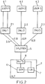
- the system comprises an OLT 1 adapted to implement the method according to the invention, the OLT 1 being connected to a plurality of ONUs 2.1, 2.2 and 2.3, each ONU being associated to a respective user 4.1, 4.2 and 4.3.
- an ONU can be in charge of the service of a plurality of users.
- the OLT 1 is connected to the ONUs 2.1, 2.2 and 2.3 via an EPON comprising a passive splitter 5 to divide the optical fiber from the OLT 1 in a plurality of optical fibers, each optical fiber from the plurality being associated to a logical link 3.11, 3.12, 3.21 and 3.31.
- each logical link can be associated to a given service (see the previous examples).
- ONU 2.1 manages both logical links 3.11 and 3.12
- ONU 2.2 manages logical link 3.21
- ONU2.3 manages logical link 3.31.
- ONUs are adapted to transmit data packets via the logical links, in timeslots that are defined by the OLT 1 via GATE messages according to the method of the invention and can send REPORT messages to the OLT 1 during their transmission timeslots.
- the OLT 1 comprises a scheduler 6, a cycle builder 7 and a network interface 8. While receiving REPORT messages from OLT, the scheduler 6 and the cycle builder 7 are adapted to perform the previously described algorithms in order to build cycles in which timeslots are allocated in a fair way to the ONUs 2.1, 2.2 and 2.3 for transmission of data packets in the different logical links 3.11, 3.12, 3.21 and 3.31.
- the interface 8 is adapted to build GATE messages, to include an identifier of a logical link in the head of the GATE message, and to receive REPORT messages from the ONUs.
- the present invention can also be embedded in a computer program product, which comprises all the features enabling the implementation of the methods described herein, and which, when loaded in an information processing system, causes the information processing system.
- Computer program means or computer program in the present context mean any expression, in any language, code or notation, of a set of instructions intended to cause a system having an information processing capability to perform a particular function either directly or after the conversion to another language.
- Such a computer program can be stored on a computer or machine readable medium allowing data, instructions, messages or message packets, and other machine readable information to be read from the medium.
- the computer or machine readable medium may include non-volatile memory, such as ROM, Flash memory, Disk drive memory, CD-ROM, and other permanent storage.
- a computer or machine readable medium may include, for example, volatile storage such as RAM, buffers, cache memory, and network circuits.
- the computer or machine readable medium may comprise computer or machine readable information in a transitory state medium such as a network link and/or a network interface, including a wired network or a wireless network, that allow a device to read such computer or machine readable information.
Landscapes
- Engineering & Computer Science (AREA)
- Computer Networks & Wireless Communication (AREA)
- Signal Processing (AREA)
- Computing Systems (AREA)
- Physics & Mathematics (AREA)
- Electromagnetism (AREA)
- Small-Scale Networks (AREA)
- Data Exchanges In Wide-Area Networks (AREA)
Claims (13)
- Verfahren zur Zuteilung von Zeitschlitzen zur Übertragung von Datenpaketen in einem passiven optischen Netzwerk, PON, wobei das PON ein optisches Leitungsterminal, OLT, umfasst, das eine oder mehr optische Netzabschlusseinheiten, ONU, verwaltet, wobei eine GATE-Nachricht aus dem OLT an eine gegebene ONU gesendet wird und dazu verwendet wird, der ONU ein oder mehrere Übertragungsfenster zuzuweisen, und eine REPORT-Nachricht ein Feedback-Mechanismus ist, der durch eine ONU dazu verwendet wird, dem OLT die Länge einer Warteschlange von wartenden Datenpaketen, die durch die ONU zu senden sind, anzuzeigen, wobei der Beginn und die Länge von Übertragungsfenstern in GATE-Nachrichten sowie Warteschlangenlängen in REPORT-Nachrichten in einem Zeitbetrag, TQ, einem festen Zeitintervall, ausgedrückt werden, jede Warteschlange mit einer logischen Verbindung LLi in dem OLT verknüpft wird, eine minimale Bitrate bi durch jede logische Verbindung für die Übertragung der Datenpakete benötigt wird, die Zeit in Zyklen aufgeteilt wird, jeder Zyklus in die gleichgroßen Zeitschlitze TQs aufgeteilt wird, eine theoretische Übertragungszeit TTTi anfänglich in dem OLT für jede logische Verbindung LLi bestimmt wird, die anfängliche TTTi auf bi basiert, jede Übertragung mit einem Overhead-Anteil verknüpft wird, das OLT eine Bildwarteschlangenlänge Qi für jede logische Verbindung LLi entsprechend Daten, die durch die logische Verbindung LLi zu senden sind, speichert, wobei das Verfahren die folgenden Schritte umfasst, die in jedem Zyklus k durch das OLT implementiert werden:- Empfangen mindestens einer REPORT-Nachricht aus mindestens einer logischen Verbindung LLi, wobei die REPORT-Nachricht eine aktualisierte Warteschlangenlänge der logischen Verbindung LLi umfasst, wobei die Länge in Zeitschlitzen ausgedrückt wird;- nach Empfangen der REPORT-Nachricht aus der logischen Verbindung LLi, Aktualisieren der Bildwarteschlangenlänge Qi auf der Grundlage der aktualisierten Warteschlangenlänge;dadurch gekennzeichnet, dass:
M eine vorangestellte maximale Anzahl von logischen Verbindungen LLi (3.11; 3.12; 3.21; 3.31) ist, die während eines Zyklus k zu versorgen sind, wobei R die Gesamtzahl von TQs in einem Zyklus ist;
und dass das Verfahren ferner umfasst:- Auswählen nur der M logischen Verbindungen LLi mit den geringsten theoretischen Übertragungszeiten TTTi, für die die Bildwarteschlangenlänge nicht Null ist;- Zuteilen, den ausgewählten M logischen Verbindungen LLi, einer Anzahl von Zeitschlitzen TQ in dem nächsten Zyklus k+1 auf der Grundlage einer Granularität Ni jeder logischen Verbindung LLi; und- Erhöhen der theoretischen Übertragungszeit TTTi jeder ausgewählten logischen Verbindung LLi auf der Grundlage von bi und Ni und Erniedrigen der Bildwarteschlangenlänge Qi der logischen Verbindung LLi der ihr zugeteilten Anzahl von Zeitschlitzen TQ;wobei Zeitschlitze TQs den ausgewählten M logischen Verbindungen LLi zugeteilt werden, bis alle Zeitschlitze TQs des nächsten Zyklus k+1 zugeteilt sind oder bis alle Bildwarteschlangenlängen Qi der ausgewählten M logischen Verbindungen LLi Null sind;
und wobei das OLT auf das Ende des Zyklus k wartet, bevor es GATE-Nachrichten an die ausgewählten ONUs überträgt, so dass sie Datenpakete in den ausgewählten M LLi während der Zeitschlitze des Zyklus k+1, die ihnen zugeteilt worden sind, übertragen können. - Verfahren nach Anspruch 1, wobei ein Vielfaches von Ni aufeinander folgenden Zeitschlitzen TQs jeder logischen Verbindung LLi (3.11; 3.12; 3.21; 3.31) zugeteilt wird, für die die Bildwarteschlange nicht Null ist, wobei Ni eine vordefinierte ganze Zahl größer als Eins, bestimmt für jede logische Verbindung LLi, ist.
- Verfahren nach Anspruch 1, wobei, falls die M Bildwarteschlangenlängen Qi der M logischen Verbindungen LLi (3.11; 3.12; 3.21; 3.31) Null sind nach dem Zuteilen mindestens eines Zeitschlitzes TQ des nächsten Zyklus k+1 zur Übertragung von Datenpaketen, Zeitschlitze TQs des nächsten Zyklus k+1, die nicht zugeteilt worden sind, den nächsten logischen Verbindungen LLi mit den geringsten theoretischen Übertragungszeiten TTTi zugeteilt werden, bis alle Zeitschlitze TQs des nächsten Zyklus k+1 zugeteilt sind oder bis alle Bildwarteschlangenlängen Qi Null sind.
- Verfahren nach Anspruch 1, wobei, bei Voranstellung einer Polling-Periode PPi als ganzzahlige Anzahl von Zyklen für jede logische Verbindung LLi (3.11; 3.12; 3.21; 3.31), Zeitschlitze TQs einer logischen Verbindung LLi zur Übertragung einer REPORT-Nachricht im nächsten Zyklus zugeteilt werden, falls die Bildwarteschlangenlänge der logischen Verbindung LLi während der Polling-Periode PPi Null bleibt.
- Verfahren nach Anspruch 1, wobei, bei Voranstellung einer maximalen Bitrate Lmax,i für jede logische Verbindung LLi (3.11; 3.12; 3.21; 3.31), bei Voranstellung einer Spitzenbitratenperiode TPBR, die Anzahl der Zeitschlitze TQs, die einer gegebenen logischen Verbindung LLi über die Spitzenbitratenperiode TPBR zugeteilt werden, durch die maximale Bitrate Lmax,i der logischen Verbindung LLi, multipliziert mit der Spitzenbitratenperiode TPBR, begrenzt wird.
- Verfahren nach Anspruch 1, wobei die REPORT-Nachricht ferner mehrere Warteschlangenmengen umfasst, die unterschiedliche kumulative Längen von Daten-Frames melden, die in der Warteschlange der logischen Verbindung LLi (3.11; 3.12; 3.21; 3.31) enthalten sind, die die REPORT-Nachricht sendet, und wobei die Anzahl Ni der aufeinander folgenden Zeitschlitze TQs, die der logischen Verbindung LLi durch das Terminal (1) zugeteilt werden, gleich einer der kumulativen Längen ist.
- Verfahren nach Anspruch 6, wobei ein Schwellenwert für jede Warteschlangenmenge bestimmt wird und als ein Vielfaches des Verhältnisses der Anzahl der in einem Zyklus beinhalteten Zeitschlitze TQs zu der vorangestellten maximalen Anzahl der logischen Verbindungen LLi, die während eines Zyklus zu versorgen sind, voreingestellt wird und wobei die gemeldete kumulative Länge gleich der kumulativen Länge von Daten-Frames einer Warteschlangenmenge ist, die den Schwellenwert der Warteschlangenmenge nicht überschreitet.
- Verfahren nach Anspruch 1, wobei die Mehrzahl der logischen Verbindungen LLi (3.11; 3.12; 3.21; 3.31) in Untermengen Sj mit einer Anzahl Nj von logischen Verbindungen LLi unterteilt wird, wobei Nj größer als oder gleich Eins ist, jede Untermenge Sj mit einer Priorität pj verknüpft wird, jede Priorität pj mit einer gegebenen minimalen Bitrate Bj verknüpft wird, die minimale Bitrate bi, die mit einer zu einer Untermenge Si gehörenden logischen Verbindung LLi verknüpft ist, durch das Verhältnis der gegebenen minimalen Bitrate Bj zu der Anzahl Nj bestimmt wird.
- Verfahren nach Anspruch 8, ferner umfassend das Aktualisieren der minimalen Bitrate bj, die mit einer zu einer Untermenge Sj gehörenden logischen Verbindung LLi (3.11; 3.12; 3.21; 3.31) verknüpft ist, immer dann, wenn eine neue logische Verbindung LLi in die Untermenge Sj eintritt oder diese verlässt.
- Verfahren nach Anspruch 8, wobei die logischen Verbindungen LLi (3.11; 3.12; 3.21; 3.31) einer selben Untermenge Sj unterschiedliche minimale Bitraten bi aufweisen, wobei die Summe der minimalen Bitraten bi der logischen Verbindungen der Untermenge Sj geringer als die mit der Priorität pj der Untermenge Sj verknüpfte gegebene minimale Bitrate Bj ist.
- Programmprodukt, das auf einem Speichermedium aufgezeichnet und durch einen Computer in Form eines Software-Agenten ausführbar ist, dadurch gekennzeichnet, dass es mindestens ein Software-Module einschließt, das so eingerichtet ist, dass es das Verfahren nach Anspruch 1 durchführt.
- Optisches Leitungsterminal, OLT, zur Zuteilung von Zeitschlitzen zur Übertragung von Datenpaketen in einem passiven optischen Netzwerk, PON, wobei das PON eine oder mehr optische Netzabschlusseinheiten, ONU, umfasst, wobei eine GATE-Nachricht aus dem OLT an eine gegebene ONU gesendet wird und dazu verwendet wird, der ONU ein oder mehrere Übertragungsfenster zuzuweisen, und eine REPORT-Nachricht ein Feedback-Mechanismus ist, der durch eine ONU dazu verwendet wird, dem OLT die Länge einer Warteschlange von wartenden Datenpaketen, die durch die ONU zu senden sind, anzuzeigen, wobei der Beginn und die Länge von Übertragungsfenstern in GATE-Nachrichten sowie Warteschlangenlängen in REPORT-Nachrichten in einem Zeitbetrag, TQ, einem festen Zeitintervall, ausgedrückt sind, jede Warteschlange mit einer logischen Verbindung LLi in dem OLT verknüpft ist, eine minimale Bitrate bi durch jede logische Verbindung für die Übertragung der Datenpakete benötigt wird, die Zeit in Zyklen aufgeteilt ist, jeder Zyklus in die gleichgroßen Zeitschlitze TQs aufgeteilt ist, eine theoretische Übertragungszeit TTTi anfänglich in dem OLT für jede logische Verbindung LLi bestimmt ist, die anfängliche TTTi auf bi basiert, jede Übertragung mit einem Overhead-Anteil verknüpft ist, das OLT eine Bildwarteschlangenlänge Qi für jede logische Verbindung LLi entsprechend Daten, die durch die logische Verbindung LLi zu senden sind, speichert, wobei das OLT Mittel umfasst zum:- Empfangen mindestens einer REPORT-Nachricht aus mindestens einer logischen Verbindung LLi, wobei die REPORT-Nachricht eine aktualisierte Warteschlangenlänge der logischen Verbindung LLi umfasst, wobei die Länge in Zeitschlitzen ausgedrückt ist;- Aktualisieren der Bildwarteschlangenlänge Qi auf der Grundlage der aktualisierten Warteschlangenlänge nach Empfangen der REPORT-Nachricht aus der logischen Verbindung LLi;dadurch gekennzeichnet, dass:M eine vorangestellte maximale Anzahl von logischen Verbindungen LLi (3.11; 3.12; 3.21; 3.31) ist, die während eines Zyklus k zu versorgen sind, wobei R die Gesamtzahl von TQs in einem Zyklus ist;und dass das OLT ferner Mittel umfasst zum:wobei Zeitschlitze TQs den ausgewählten M logischen Verbindungen LLi zugeteilt werden, bis alle Zeitschlitze TQs des nächsten Zyklus k+1 zugeteilt sind oder bis alle Bildwarteschlangenlängen Qi der M logischen Verbindungen LLi Null sind;- Auswählen nur der M logischen Verbindungen LLi mit den geringsten theoretischen Übertragungszeiten TTTi, für die die Bildwarteschlangenlänge nicht Null ist;- Zuteilen, den ausgewählten M logischen Verbindungen LLi, einer Anzahl von Zeitschlitzen TQ in dem nächsten Zyklus k+1 auf der Grundlage einer Granularität Ni jeder logischen Verbindung LLi; und- Erhöhen der theoretischen Übertragungszeit TTTi jeder ausgewählten logischen Verbindung LLi auf der Grundlage von bi und Ni und Erniedrigen der Bildwarteschlangenlänge Qi der logischen Verbindung LLi der ihr zugeteilten Anzahl von Zeitschlitzen TQ;
und wobei das OLT auf das Ende des Zyklus k wartet, bevor es GATE-Nachrichten an die ausgewählten ONUs überträgt, so dass sie Datenpakete in den ausgewählten M LLi während der Zeitschlitze des Zyklus k+1, die ihnen zugeteilt worden sind, übertragen können. - Passives optisches Netzwerk, PON, das ein optisches Leitungsterminal, OLT, umfasst, das eine oder mehr optische Netzabschlusseinheiten, ONU, verwaltet, wobei eine GATE-Nachricht aus dem OLT an eine gegebene ONU gesendet wird und dazu verwendet wird, der ONU ein oder mehrere Übertragungsfenster zuzuweisen, und eine REPORT-Nachricht ein Feedback-Mechanismus ist, der durch eine ONU dazu verwendet wird, dem OLT die Länge einer Warteschlange von wartenden Datenpaketen, die durch die ONU zu senden sind, anzuzeigen, wobei der Beginn und die Länge von Übertragungsfenstern in GATE-Nachrichten sowie Warteschlangenlängen in REPORT-Nachrichten in einem Zeitbetrag, TQ, einem festen Zeitintervall, ausgedrückt sind, jede Warteschlange mit einer logischen Verbindung LLi in dem OLT verknüpft ist, eine minimale Bitrate bi durch jede logische Verbindung für die Übertragung der Datenpakete benötigt wird, die Zeit in Zyklen aufgeteilt ist, jeder Zyklus in die gleichgroßen Zeitschlitze TQs aufgeteilt ist, eine theoretische Übertragungszeit TTTi anfänglich in dem Terminal für jede logische Verbindung LLi bestimmt ist, die anfängliche TTTi auf bi basiert, jede Übertragung mit einem Overhead-Anteil verknüpft ist, das OLT eine Bildwarteschlangenlänge Qi für jede logische Verbindung LLi entsprechend Daten, die durch die logische Verbindung LLi zu senden sind, speichert, wobei das OLT Mittel umfasst zum:- Empfangen mindestens einer REPORT-Nachricht aus mindestens einer logischen Verbindung LLi, wobei die REPORT-Nachricht eine aktualisierte Warteschlangenlänge der logischen Verbindung LLi umfasst, wobei die Länge in Zeitschlitzen ausgedrückt ist;- Aktualisieren der Bildwarteschlangenlänge Qi auf der Grundlage der aktualisierten Warteschlangenlänge nach Empfangen der REPORT-Nachricht aus der logischen Verbindung LLi;dadurch gekennzeichnet, dass:- M eine vorangestellte maximale Anzahl von logischen Verbindungen LLi (3.11; 3.12; 3.21; 3.31) ist, die während eines Zyklus k zu versorgen sind, wobei R die Gesamtzahl von TQs in einem Zyklus ist;und dass das OLT ferner Mittel umfasst zum:- Auswählen nur der M logischen Verbindungen LLi mit den geringsten theoretischen Übertragungszeiten TTTi, für die die Bildwarteschlangenlänge nicht Null ist;- Zuteilen, den ausgewählten M logischen Verbindungen LLi, einer Anzahl von Zeitschlitzen TQ in dem nächsten Zyklus k+1 auf der Grundlage einer Granularität Ni jeder logischen Verbindung LLi; und- Erhöhen der theoretischen Übertragungszeit TTTi jeder ausgewählten logischen Verbindung LLi auf der Grundlage von bi und Ni und Erniedrigen der Bildwarteschlangenlänge Qi der logischen Verbindung LLi der ihr zugeteilten Anzahl von Zeitschlitzen TQ;wobei Zeitschlitze TQs den ausgewählten M logischen Verbindungen LLi zugeteilt werden, bis alle Zeitschlitze TQs des nächsten Zyklus k+1 zugeteilt sind oder bis alle Bildwarteschlangenlängen Qi der ausgewählten M logischen Verbindungen LLi Null sind;
und wobei das OLT auf das Ende des Zyklus k wartet, bevor es GATE-Nachrichten an die ausgewählten ONUs überträgt, so dass sie Datenpakete in den ausgewählten M LLi während der Zeitschlitze des Zyklus k+1, die ihnen zugeteilt worden sind, übertragen können.
Priority Applications (7)
| Application Number | Priority Date | Filing Date | Title |
|---|---|---|---|
| EP11305131.2A EP2487833B1 (de) | 2011-02-09 | 2011-02-09 | Optimierter Zeitplaner für dynamische Bandbreite |
| KR1020137021034A KR20140021540A (ko) | 2011-02-09 | 2012-02-01 | 최적화된 동적 대역폭 스케줄러 |
| JP2013552907A JP5897605B2 (ja) | 2011-02-09 | 2012-02-01 | 最適化された動的帯域幅スケジューラ |
| US13/984,160 US9647760B2 (en) | 2011-02-09 | 2012-02-01 | Optimized dynamic bandwidth scheduler |
| PCT/EP2012/051716 WO2012107340A1 (en) | 2011-02-09 | 2012-02-01 | Optimized dynamic bandwidth scheduler |
| CN201280008337.6A CN103430486B (zh) | 2011-02-09 | 2012-02-01 | 最佳动态带宽调度器 |
| TW101104116A TWI549456B (zh) | 2011-02-09 | 2012-02-08 | 最佳化之動態頻寬排程器 |
Applications Claiming Priority (1)
| Application Number | Priority Date | Filing Date | Title |
|---|---|---|---|
| EP11305131.2A EP2487833B1 (de) | 2011-02-09 | 2011-02-09 | Optimierter Zeitplaner für dynamische Bandbreite |
Publications (2)
| Publication Number | Publication Date |
|---|---|
| EP2487833A1 EP2487833A1 (de) | 2012-08-15 |
| EP2487833B1 true EP2487833B1 (de) | 2018-07-04 |
Family
ID=44041671
Family Applications (1)
| Application Number | Title | Priority Date | Filing Date |
|---|---|---|---|
| EP11305131.2A Not-in-force EP2487833B1 (de) | 2011-02-09 | 2011-02-09 | Optimierter Zeitplaner für dynamische Bandbreite |
Country Status (7)
| Country | Link |
|---|---|
| US (1) | US9647760B2 (de) |
| EP (1) | EP2487833B1 (de) |
| JP (1) | JP5897605B2 (de) |
| KR (1) | KR20140021540A (de) |
| CN (1) | CN103430486B (de) |
| TW (1) | TWI549456B (de) |
| WO (1) | WO2012107340A1 (de) |
Families Citing this family (14)
| Publication number | Priority date | Publication date | Assignee | Title |
|---|---|---|---|---|
| EP2645735B1 (de) * | 2012-03-29 | 2014-04-23 | Mitsubishi Electric R&D Centre Europe B.V. | Verfahren und Vorrichtung zur optimierten Zeitplanung in einer Mehrprozess-Umgebung |
| US9898317B2 (en) | 2012-06-06 | 2018-02-20 | Juniper Networks, Inc. | Physical path determination for virtual network packet flows |
| JP5876941B2 (ja) * | 2012-11-14 | 2016-03-02 | 日本電信電話株式会社 | 光加入者通信システム、光加入者通信方法、上位装置及び光加入者線終端装置 |
| US9331812B2 (en) * | 2012-12-21 | 2016-05-03 | Futurewei Technologies, Inc. | Round trip time aware dynamic bandwidth allocation for ethernet passive optical network over coaxial network |
| KR102105186B1 (ko) * | 2013-03-18 | 2020-04-28 | 한국전자통신연구원 | 수동형 광 가입자 망의 광 선로 종단 장치 및 이를 이용한 상향 대역 제어 방법 |
| US9485191B2 (en) * | 2014-03-31 | 2016-11-01 | Juniper Networks, Inc. | Flow-control within a high-performance, scalable and drop-free data center switch fabric |
| US9703743B2 (en) | 2014-03-31 | 2017-07-11 | Juniper Networks, Inc. | PCIe-based host network accelerators (HNAS) for data center overlay network |
| US9479457B2 (en) | 2014-03-31 | 2016-10-25 | Juniper Networks, Inc. | High-performance, scalable and drop-free data center switch fabric |
| JP6419340B2 (ja) * | 2014-12-16 | 2018-11-07 | ローベルト ボツシユ ゲゼルシヤフト ミツト ベシユレンクテル ハフツングRobert Bosch Gmbh | 非決定論的ネットワークを介してネットワークデバイス間でデータを送信する方法 |
| FR3030962B1 (fr) * | 2014-12-19 | 2018-04-13 | Airbus Operations | Systeme de communication d'un aeronef |
| TWI612785B (zh) * | 2015-05-27 | 2018-01-21 | 財團法人資訊工業策進會 | 聚合流量控制裝置、方法及其電腦程式產品 |
| US10243840B2 (en) | 2017-03-01 | 2019-03-26 | Juniper Networks, Inc. | Network interface card switching for virtual networks |
| CN108540221B (zh) | 2017-03-06 | 2022-12-02 | 中兴通讯股份有限公司 | 数据发送方法及装置 |
| US10841238B2 (en) | 2017-12-20 | 2020-11-17 | At&T Intellectual Property I, L.P. | Prioritized network based on service and user device |
Family Cites Families (26)
| Publication number | Priority date | Publication date | Assignee | Title |
|---|---|---|---|---|
| ES2303350T3 (es) * | 1998-05-15 | 2008-08-01 | Alcatel Lucent | Metodo para asignar intervalos de tiempo en sentido ascendente a un terminal de red y terminal de red y controlador de acceso al medio para poner en practica dicho metodo. |
| KR20030064775A (ko) * | 2000-10-26 | 2003-08-02 | 웨이브7 옵틱스 인코포레이티드 | 광통신네트워크의 하향스트림 패킷 처리 방법 및 시스템 |
| US6987753B2 (en) * | 2001-10-09 | 2006-01-17 | Alcatel Canada Inc | Apparatus and method for dynamic bandwidth allocation with minimum bandwidth guarantee |
| KR100547722B1 (ko) * | 2001-11-10 | 2006-02-01 | 삼성전자주식회사 | 기가비트 이더넷 수동 광 네트워크 시스템 및 그 매체접속 제어 방법 |
| US7020484B2 (en) * | 2002-10-29 | 2006-03-28 | Qualcomm Incorporated | Controlling multiple modems in a wireless terminal using energy-per-bit determinations |
| US7593418B1 (en) * | 2004-03-23 | 2009-09-22 | Marvell Israel (M.I.S.L.) Ltd. | Apparatus and a method for allocating upstream bandwidth of a shared upstream channel of an optical network |
| US20060067269A1 (en) * | 2004-09-27 | 2006-03-30 | Enrico Jugl | Method of scheduling users in wireless communication networks |
| US20060209684A1 (en) * | 2005-03-18 | 2006-09-21 | Via Technologies, Inc. | Data rate controller, and method of control thereof |
| EP1796313A1 (de) * | 2005-12-06 | 2007-06-13 | Siemens Aktiengesellschaft | Verfahren, Kommunikationssystem und zentrale Kommunikationseinheit zur Steuerung der Zugriffe auf einen gemeinsamen Datenträger |
| US20100074628A1 (en) * | 2006-05-24 | 2010-03-25 | Mitsubishi Electric Corporation | Optical communication system, station-side apparatus, and subscriber-side apparatus |
| JP4065892B1 (ja) * | 2006-10-13 | 2008-03-26 | 株式会社日立コミュニケーションテクノロジー | Ponシステムおよびそのレンジング方法 |
| KR100933158B1 (ko) * | 2006-11-15 | 2009-12-21 | 삼성전자주식회사 | 이동통신 시스템에서의 버퍼 상태 보고 방법 및 장치 |
| JP4340692B2 (ja) * | 2007-02-02 | 2009-10-07 | 株式会社日立コミュニケーションテクノロジー | 受動光網システムおよびその運用方法 |
| TW201032523A (en) * | 2008-01-17 | 2010-09-01 | Interdigital Tech Corp | Method and apparatus for reference transport channel selection |
| JP4942680B2 (ja) * | 2008-02-08 | 2012-05-30 | 株式会社日立製作所 | 受動光網システム、光多重終端装置及び受動光網システムの通信方法 |
| US8532032B2 (en) * | 2008-03-18 | 2013-09-10 | Blackberry Limited | Dynamic scheduling overwriting of semi-persistent allocation in an uplink |
| WO2010022168A1 (en) * | 2008-08-22 | 2010-02-25 | Research In Motion Limited | Network quality of service update control |
| WO2010060463A1 (en) * | 2008-11-25 | 2010-06-03 | Telefonaktiebolaget L M Ericsson (Publ) | Method and apparatus for statistical multiplexing |
| US20100182947A1 (en) * | 2008-11-26 | 2010-07-22 | Je-Hong Jong | Method and system of providing link adaptation for maximizing throughput in mobile satellite systems |
| TWI396401B (zh) * | 2008-12-19 | 2013-05-11 | Chunghwa Telecom Co Ltd | Dynamic Bandwidth Assignment Method for Passive Fiber Network |
| US8335235B2 (en) * | 2009-03-20 | 2012-12-18 | Broadcom Corporation | Methods and apparatus for extending MAC control message in EPON |
| CN101534254B (zh) * | 2009-04-21 | 2011-05-04 | 华为技术有限公司 | 一种队列报告方法、装置和无源光网络系统 |
| CN101883294B (zh) * | 2009-05-07 | 2013-08-07 | 华为技术有限公司 | 上行带宽分配方法和装置 |
| JP5115534B2 (ja) * | 2009-10-14 | 2013-01-09 | 富士通株式会社 | 無線通信システム及び無線通信方法 |
| ES2376328B1 (es) * | 2010-03-31 | 2013-01-29 | Telefónica, S.A. | Método y entidad de red para asignación de recursos en redes de comunicación de radio móvil. |
| US8514703B2 (en) * | 2010-11-11 | 2013-08-20 | Qualcomm Incorporated | Scheduling of logical channels in a wireless communication system |
-
2011
- 2011-02-09 EP EP11305131.2A patent/EP2487833B1/de not_active Not-in-force
-
2012
- 2012-02-01 JP JP2013552907A patent/JP5897605B2/ja not_active Expired - Fee Related
- 2012-02-01 KR KR1020137021034A patent/KR20140021540A/ko not_active Application Discontinuation
- 2012-02-01 CN CN201280008337.6A patent/CN103430486B/zh not_active Expired - Fee Related
- 2012-02-01 US US13/984,160 patent/US9647760B2/en not_active Expired - Fee Related
- 2012-02-01 WO PCT/EP2012/051716 patent/WO2012107340A1/en active Application Filing
- 2012-02-08 TW TW101104116A patent/TWI549456B/zh not_active IP Right Cessation
Non-Patent Citations (1)
| Title |
|---|
| None * |
Also Published As
| Publication number | Publication date |
|---|---|
| CN103430486A (zh) | 2013-12-04 |
| JP2014508463A (ja) | 2014-04-03 |
| WO2012107340A1 (en) | 2012-08-16 |
| TWI549456B (zh) | 2016-09-11 |
| JP5897605B2 (ja) | 2016-03-30 |
| EP2487833A1 (de) | 2012-08-15 |
| CN103430486B (zh) | 2016-06-29 |
| US20130315596A1 (en) | 2013-11-28 |
| TW201234812A (en) | 2012-08-16 |
| US9647760B2 (en) | 2017-05-09 |
| KR20140021540A (ko) | 2014-02-20 |
Similar Documents
| Publication | Publication Date | Title |
|---|---|---|
| EP2487833B1 (de) | Optimierter Zeitplaner für dynamische Bandbreite | |
| Luo et al. | Bandwidth allocation for multiservice access on EPONs | |
| US7808913B2 (en) | Dynamic bandwidth allocation and service differentiation for broadband passive optical networks | |
| EP1786149A1 (de) | Verfahren, Kommunikationssystem sowie zentrales und peripheres Kommunikationsgerät zur Kontrolle des Zugriffs auf ein Medium mit gemeinsamer Benutzung | |
| Kanonakis et al. | Offset-based scheduling with flexible intervals for evolving GPON networks | |
| Orphanoudakis et al. | Performance evaluation of GPON vs EPON for multi‐service access | |
| Nikolova et al. | Dynamic bandwidth allocation algorithms for Ethernet passive optical networks with threshold reporting | |
| Zheng et al. | Adaptive scheduling algorithms for Ethernet passive optical networks | |
| Luo et al. | Dynamic upstream bandwidth allocation over Ethernet PONs | |
| Rahman et al. | Control message scheduling algorithm for improving throughput and jitter performance of the MHSSR DBA scheme of PON | |
| Zhu et al. | Hierarchical scheduling to support differentiated services in Ethernet passive optical networks | |
| Hwang et al. | Adaptive priority scheduling integrated with B-DBA for revenue optimization with QoS and CoS guarantees in GPON | |
| Kim et al. | HUHG: high utilization and hybrid granting algorithm for EPON | |
| Hsueh et al. | A new media access control protocol with quality of service and fairness guarantee in Ethernet-based passive optical networks | |
| Lin et al. | Supporting triple-play services with private networking over WDM EPONs | |
| Ngo et al. | Enforcing bandwidth allocation and traffic conformance in Passive Optical Networks | |
| Ngo et al. | A priority-based multiservice dynamic bandwidth allocation for Ethernet Passive Optical networks | |
| Yeon et al. | High utilization and hybrid granting algorithm for EPON | |
| Orphanoudakis et al. | Efficient resource allocation with service guarantees in passive optical networks | |
| Prahmkaew | Performance Evaluation of Adaptive Rate Control (ARC) over Ethernet Based PONs (EPONs) | |
| Zapata et al. | Investigation of future optical metro ring networks based on 100-gigabit metro ethernet (100gbme) | |
| EP2645735B1 (de) | Verfahren und Vorrichtung zur optimierten Zeitplanung in einer Mehrprozess-Umgebung | |
| Orphanoudakis et al. | Dynamic Traffic Multiplexing over EPONs Achieving Guaranteed QoS and Optimal Bandwidth Utilization | |
| Yang et al. | Dynamic bandwidth allocation in EPON | |
| Radivojević et al. | SUCCESSFUL MIGRATION OF EPON TO WDM EPON. |
Legal Events
| Date | Code | Title | Description |
|---|---|---|---|
| PUAI | Public reference made under article 153(3) epc to a published international application that has entered the european phase |
Free format text: ORIGINAL CODE: 0009012 |
|
| AK | Designated contracting states |
Kind code of ref document: A1 Designated state(s): AL AT BE BG CH CY CZ DE DK EE ES FI FR GB GR HR HU IE IS IT LI LT LU LV MC MK MT NL NO PL PT RO RS SE SI SK SM TR |
|
| AX | Request for extension of the european patent |
Extension state: BA ME |
|
| 17P | Request for examination filed |
Effective date: 20130207 |
|
| 17Q | First examination report despatched |
Effective date: 20141103 |
|
| STAA | Information on the status of an ep patent application or granted ep patent |
Free format text: STATUS: EXAMINATION IS IN PROGRESS |
|
| GRAP | Despatch of communication of intention to grant a patent |
Free format text: ORIGINAL CODE: EPIDOSNIGR1 |
|
| STAA | Information on the status of an ep patent application or granted ep patent |
Free format text: STATUS: GRANT OF PATENT IS INTENDED |
|
| INTG | Intention to grant announced |
Effective date: 20180328 |
|
| GRAS | Grant fee paid |
Free format text: ORIGINAL CODE: EPIDOSNIGR3 |
|
| GRAA | (expected) grant |
Free format text: ORIGINAL CODE: 0009210 |
|
| STAA | Information on the status of an ep patent application or granted ep patent |
Free format text: STATUS: THE PATENT HAS BEEN GRANTED |
|
| AK | Designated contracting states |
Kind code of ref document: B1 Designated state(s): AL AT BE BG CH CY CZ DE DK EE ES FI FR GB GR HR HU IE IS IT LI LT LU LV MC MK MT NL NO PL PT RO RS SE SI SK SM TR |
|
| REG | Reference to a national code |
Ref country code: GB Ref legal event code: FG4D |
|
| REG | Reference to a national code |
Ref country code: CH Ref legal event code: EP |
|
| REG | Reference to a national code |
Ref country code: AT Ref legal event code: REF Ref document number: 1015660 Country of ref document: AT Kind code of ref document: T Effective date: 20180715 |
|
| REG | Reference to a national code |
Ref country code: IE Ref legal event code: FG4D |
|
| REG | Reference to a national code |
Ref country code: DE Ref legal event code: R096 Ref document number: 602011049717 Country of ref document: DE |
|
| REG | Reference to a national code |
Ref country code: NL Ref legal event code: MP Effective date: 20180704 |
|
| REG | Reference to a national code |
Ref country code: LT Ref legal event code: MG4D |
|
| REG | Reference to a national code |
Ref country code: AT Ref legal event code: MK05 Ref document number: 1015660 Country of ref document: AT Kind code of ref document: T Effective date: 20180704 |
|
| PG25 | Lapsed in a contracting state [announced via postgrant information from national office to epo] |
Ref country code: NL Free format text: LAPSE BECAUSE OF FAILURE TO SUBMIT A TRANSLATION OF THE DESCRIPTION OR TO PAY THE FEE WITHIN THE PRESCRIBED TIME-LIMIT Effective date: 20180704 |
|
| PG25 | Lapsed in a contracting state [announced via postgrant information from national office to epo] |
Ref country code: CZ Free format text: LAPSE BECAUSE OF FAILURE TO SUBMIT A TRANSLATION OF THE DESCRIPTION OR TO PAY THE FEE WITHIN THE PRESCRIBED TIME-LIMIT Effective date: 20180704 Ref country code: BG Free format text: LAPSE BECAUSE OF FAILURE TO SUBMIT A TRANSLATION OF THE DESCRIPTION OR TO PAY THE FEE WITHIN THE PRESCRIBED TIME-LIMIT Effective date: 20181004 Ref country code: LT Free format text: LAPSE BECAUSE OF FAILURE TO SUBMIT A TRANSLATION OF THE DESCRIPTION OR TO PAY THE FEE WITHIN THE PRESCRIBED TIME-LIMIT Effective date: 20180704 Ref country code: IS Free format text: LAPSE BECAUSE OF FAILURE TO SUBMIT A TRANSLATION OF THE DESCRIPTION OR TO PAY THE FEE WITHIN THE PRESCRIBED TIME-LIMIT Effective date: 20181104 Ref country code: RS Free format text: LAPSE BECAUSE OF FAILURE TO SUBMIT A TRANSLATION OF THE DESCRIPTION OR TO PAY THE FEE WITHIN THE PRESCRIBED TIME-LIMIT Effective date: 20180704 Ref country code: PL Free format text: LAPSE BECAUSE OF FAILURE TO SUBMIT A TRANSLATION OF THE DESCRIPTION OR TO PAY THE FEE WITHIN THE PRESCRIBED TIME-LIMIT Effective date: 20180704 Ref country code: SE Free format text: LAPSE BECAUSE OF FAILURE TO SUBMIT A TRANSLATION OF THE DESCRIPTION OR TO PAY THE FEE WITHIN THE PRESCRIBED TIME-LIMIT Effective date: 20180704 Ref country code: AT Free format text: LAPSE BECAUSE OF FAILURE TO SUBMIT A TRANSLATION OF THE DESCRIPTION OR TO PAY THE FEE WITHIN THE PRESCRIBED TIME-LIMIT Effective date: 20180704 Ref country code: FI Free format text: LAPSE BECAUSE OF FAILURE TO SUBMIT A TRANSLATION OF THE DESCRIPTION OR TO PAY THE FEE WITHIN THE PRESCRIBED TIME-LIMIT Effective date: 20180704 Ref country code: NO Free format text: LAPSE BECAUSE OF FAILURE TO SUBMIT A TRANSLATION OF THE DESCRIPTION OR TO PAY THE FEE WITHIN THE PRESCRIBED TIME-LIMIT Effective date: 20181004 Ref country code: GR Free format text: LAPSE BECAUSE OF FAILURE TO SUBMIT A TRANSLATION OF THE DESCRIPTION OR TO PAY THE FEE WITHIN THE PRESCRIBED TIME-LIMIT Effective date: 20181005 |
|
| PG25 | Lapsed in a contracting state [announced via postgrant information from national office to epo] |
Ref country code: ES Free format text: LAPSE BECAUSE OF FAILURE TO SUBMIT A TRANSLATION OF THE DESCRIPTION OR TO PAY THE FEE WITHIN THE PRESCRIBED TIME-LIMIT Effective date: 20180704 Ref country code: HR Free format text: LAPSE BECAUSE OF FAILURE TO SUBMIT A TRANSLATION OF THE DESCRIPTION OR TO PAY THE FEE WITHIN THE PRESCRIBED TIME-LIMIT Effective date: 20180704 Ref country code: AL Free format text: LAPSE BECAUSE OF FAILURE TO SUBMIT A TRANSLATION OF THE DESCRIPTION OR TO PAY THE FEE WITHIN THE PRESCRIBED TIME-LIMIT Effective date: 20180704 Ref country code: LV Free format text: LAPSE BECAUSE OF FAILURE TO SUBMIT A TRANSLATION OF THE DESCRIPTION OR TO PAY THE FEE WITHIN THE PRESCRIBED TIME-LIMIT Effective date: 20180704 |
|
| REG | Reference to a national code |
Ref country code: DE Ref legal event code: R097 Ref document number: 602011049717 Country of ref document: DE |
|
| PG25 | Lapsed in a contracting state [announced via postgrant information from national office to epo] |
Ref country code: EE Free format text: LAPSE BECAUSE OF FAILURE TO SUBMIT A TRANSLATION OF THE DESCRIPTION OR TO PAY THE FEE WITHIN THE PRESCRIBED TIME-LIMIT Effective date: 20180704 Ref country code: RO Free format text: LAPSE BECAUSE OF FAILURE TO SUBMIT A TRANSLATION OF THE DESCRIPTION OR TO PAY THE FEE WITHIN THE PRESCRIBED TIME-LIMIT Effective date: 20180704 Ref country code: IT Free format text: LAPSE BECAUSE OF FAILURE TO SUBMIT A TRANSLATION OF THE DESCRIPTION OR TO PAY THE FEE WITHIN THE PRESCRIBED TIME-LIMIT Effective date: 20180704 |
|
| PLBE | No opposition filed within time limit |
Free format text: ORIGINAL CODE: 0009261 |
|
| STAA | Information on the status of an ep patent application or granted ep patent |
Free format text: STATUS: NO OPPOSITION FILED WITHIN TIME LIMIT |
|
| PG25 | Lapsed in a contracting state [announced via postgrant information from national office to epo] |
Ref country code: SM Free format text: LAPSE BECAUSE OF FAILURE TO SUBMIT A TRANSLATION OF THE DESCRIPTION OR TO PAY THE FEE WITHIN THE PRESCRIBED TIME-LIMIT Effective date: 20180704 Ref country code: SK Free format text: LAPSE BECAUSE OF FAILURE TO SUBMIT A TRANSLATION OF THE DESCRIPTION OR TO PAY THE FEE WITHIN THE PRESCRIBED TIME-LIMIT Effective date: 20180704 Ref country code: DK Free format text: LAPSE BECAUSE OF FAILURE TO SUBMIT A TRANSLATION OF THE DESCRIPTION OR TO PAY THE FEE WITHIN THE PRESCRIBED TIME-LIMIT Effective date: 20180704 |
|
| 26N | No opposition filed |
Effective date: 20190405 |
|
| PG25 | Lapsed in a contracting state [announced via postgrant information from national office to epo] |
Ref country code: SI Free format text: LAPSE BECAUSE OF FAILURE TO SUBMIT A TRANSLATION OF THE DESCRIPTION OR TO PAY THE FEE WITHIN THE PRESCRIBED TIME-LIMIT Effective date: 20180704 |
|
| REG | Reference to a national code |
Ref country code: DE Ref legal event code: R119 Ref document number: 602011049717 Country of ref document: DE |
|
| REG | Reference to a national code |
Ref country code: CH Ref legal event code: PL |
|
| GBPC | Gb: european patent ceased through non-payment of renewal fee |
Effective date: 20190209 |
|
| PG25 | Lapsed in a contracting state [announced via postgrant information from national office to epo] |
Ref country code: MC Free format text: LAPSE BECAUSE OF FAILURE TO SUBMIT A TRANSLATION OF THE DESCRIPTION OR TO PAY THE FEE WITHIN THE PRESCRIBED TIME-LIMIT Effective date: 20180704 Ref country code: LU Free format text: LAPSE BECAUSE OF NON-PAYMENT OF DUE FEES Effective date: 20190209 |
|
| REG | Reference to a national code |
Ref country code: BE Ref legal event code: MM Effective date: 20190228 |
|
| REG | Reference to a national code |
Ref country code: IE Ref legal event code: MM4A |
|
| PG25 | Lapsed in a contracting state [announced via postgrant information from national office to epo] |
Ref country code: LI Free format text: LAPSE BECAUSE OF NON-PAYMENT OF DUE FEES Effective date: 20190228 Ref country code: CH Free format text: LAPSE BECAUSE OF NON-PAYMENT OF DUE FEES Effective date: 20190228 |
|
| PG25 | Lapsed in a contracting state [announced via postgrant information from national office to epo] |
Ref country code: IE Free format text: LAPSE BECAUSE OF NON-PAYMENT OF DUE FEES Effective date: 20190209 Ref country code: GB Free format text: LAPSE BECAUSE OF NON-PAYMENT OF DUE FEES Effective date: 20190209 Ref country code: DE Free format text: LAPSE BECAUSE OF NON-PAYMENT OF DUE FEES Effective date: 20190903 |
|
| PG25 | Lapsed in a contracting state [announced via postgrant information from national office to epo] |
Ref country code: FR Free format text: LAPSE BECAUSE OF NON-PAYMENT OF DUE FEES Effective date: 20190228 Ref country code: BE Free format text: LAPSE BECAUSE OF NON-PAYMENT OF DUE FEES Effective date: 20190228 |
|
| PG25 | Lapsed in a contracting state [announced via postgrant information from national office to epo] |
Ref country code: TR Free format text: LAPSE BECAUSE OF FAILURE TO SUBMIT A TRANSLATION OF THE DESCRIPTION OR TO PAY THE FEE WITHIN THE PRESCRIBED TIME-LIMIT Effective date: 20180704 |
|
| PG25 | Lapsed in a contracting state [announced via postgrant information from national office to epo] |
Ref country code: PT Free format text: LAPSE BECAUSE OF FAILURE TO SUBMIT A TRANSLATION OF THE DESCRIPTION OR TO PAY THE FEE WITHIN THE PRESCRIBED TIME-LIMIT Effective date: 20181105 Ref country code: MT Free format text: LAPSE BECAUSE OF NON-PAYMENT OF DUE FEES Effective date: 20190209 |
|
| PG25 | Lapsed in a contracting state [announced via postgrant information from national office to epo] |
Ref country code: CY Free format text: LAPSE BECAUSE OF FAILURE TO SUBMIT A TRANSLATION OF THE DESCRIPTION OR TO PAY THE FEE WITHIN THE PRESCRIBED TIME-LIMIT Effective date: 20180704 |
|
| PG25 | Lapsed in a contracting state [announced via postgrant information from national office to epo] |
Ref country code: HU Free format text: LAPSE BECAUSE OF FAILURE TO SUBMIT A TRANSLATION OF THE DESCRIPTION OR TO PAY THE FEE WITHIN THE PRESCRIBED TIME-LIMIT; INVALID AB INITIO Effective date: 20110209 |
|
| PG25 | Lapsed in a contracting state [announced via postgrant information from national office to epo] |
Ref country code: MK Free format text: LAPSE BECAUSE OF FAILURE TO SUBMIT A TRANSLATION OF THE DESCRIPTION OR TO PAY THE FEE WITHIN THE PRESCRIBED TIME-LIMIT Effective date: 20180704 |