EP2484847A1 - Automatic cleaning machine driven by hydraulic power from bottom of swimming pool and hydraulic drive jaw type clutch impeller combination thereof - Google Patents
Automatic cleaning machine driven by hydraulic power from bottom of swimming pool and hydraulic drive jaw type clutch impeller combination thereof Download PDFInfo
- Publication number
- EP2484847A1 EP2484847A1 EP10819831A EP10819831A EP2484847A1 EP 2484847 A1 EP2484847 A1 EP 2484847A1 EP 10819831 A EP10819831 A EP 10819831A EP 10819831 A EP10819831 A EP 10819831A EP 2484847 A1 EP2484847 A1 EP 2484847A1
- Authority
- EP
- European Patent Office
- Prior art keywords
- cleaner
- impeller
- swimming pool
- hydraulic
- housing
- Prior art date
- Legal status (The legal status is an assumption and is not a legal conclusion. Google has not performed a legal analysis and makes no representation as to the accuracy of the status listed.)
- Granted
Links
- 230000009182 swimming Effects 0.000 title claims abstract description 44
- 238000004140 cleaning Methods 0.000 title abstract description 18
- XLYOFNOQVPJJNP-UHFFFAOYSA-N water Substances O XLYOFNOQVPJJNP-UHFFFAOYSA-N 0.000 claims abstract description 101
- 208000034699 Vitreous floaters Diseases 0.000 claims abstract description 11
- 230000009471 action Effects 0.000 claims abstract description 10
- 238000002347 injection Methods 0.000 claims abstract description 10
- 239000007924 injection Substances 0.000 claims abstract description 10
- 230000008859 change Effects 0.000 claims abstract description 9
- 238000004891 communication Methods 0.000 claims description 8
- VYPSYNLAJGMNEJ-UHFFFAOYSA-N Silicium dioxide Chemical compound O=[Si]=O VYPSYNLAJGMNEJ-UHFFFAOYSA-N 0.000 claims description 4
- 230000000712 assembly Effects 0.000 claims description 4
- 238000000429 assembly Methods 0.000 claims description 4
- 239000000741 silica gel Substances 0.000 claims description 4
- 229910002027 silica gel Inorganic materials 0.000 claims description 4
- 239000007769 metal material Substances 0.000 claims description 3
- 239000010865 sewage Substances 0.000 abstract description 13
- 238000010586 diagram Methods 0.000 description 14
- 238000000034 method Methods 0.000 description 5
- 238000005516 engineering process Methods 0.000 description 3
- 241000894006 Bacteria Species 0.000 description 1
- 241000195493 Cryptophyta Species 0.000 description 1
- 238000009395 breeding Methods 0.000 description 1
- 230000001488 breeding effect Effects 0.000 description 1
- 238000007599 discharging Methods 0.000 description 1
- 230000036541 health Effects 0.000 description 1
- 238000009434 installation Methods 0.000 description 1
- 230000007246 mechanism Effects 0.000 description 1
- 239000002184 metal Substances 0.000 description 1
- 239000000126 substance Substances 0.000 description 1
Images


Classifications
-
- E—FIXED CONSTRUCTIONS
- E04—BUILDING
- E04H—BUILDINGS OR LIKE STRUCTURES FOR PARTICULAR PURPOSES; SWIMMING OR SPLASH BATHS OR POOLS; MASTS; FENCING; TENTS OR CANOPIES, IN GENERAL
- E04H4/00—Swimming or splash baths or pools
- E04H4/14—Parts, details or accessories not otherwise provided for
- E04H4/16—Parts, details or accessories not otherwise provided for specially adapted for cleaning
- E04H4/1654—Self-propelled cleaners
Definitions
- the goal of the present invention is to design a swimming pool bottom hydraulic pushed automatic cleaner with simple structure.
- An impeller hydraulic driven clutch is used for making the impellers on the two ends of double extension shaft of single motor change the direction to drive the cleaner to travel.
- the leading and trailing edges of the cleaner and the longitudinal shaft of the cleaner form different included angles.
- the leading edge or trailing edge of the housing is a part touching pool wall, after the cleaner automatically adjusts the direction when the leading edge touches the wall or the trailing edge touches the wall, it has different travel directions when traveling in an opposite direction, the route along which the cleaner travels reversely after touching the wall for a long period of time is one-way jagged. Therefore, the cleaner can automatically clean the bottom of the swimming pool regularly.
- a swimming pool bottom hydraulic pushed automatic cleaner comprises an underwater cleaner and a control power supply, which are connected together by a cable
- the underwater cleaner comprises a housing cover part, a housing body part, a filter, a double extension shaft motor assembly, a hydraulic driven jaw-type clutch impeller combination, a water inlet/outlet flow passage, a wheel and bracket, an isolated hood and a cable
- the housing cover part, the housing body part, the double extension shaft motor assembly, the hydraulic driven jaw-type clutch impeller combination, the water inlet/outlet flow passage and the cable constitute an axial-flow pump with double water injection nozzle
- both ends of the motor of the double extension shaft motor assembly are provided with outrigger shafts
- the motor is watertight
- the hydraulic driven jaw-type clutch impeller combination is installed on the outrigger shaft of the double extension shaft motor assembly
- the water inlet/outlet flow passage comprises a flow passage, a flow guide cover and a swinging cap
- the water inlet/outlet flow passage is a water inlet/out
Landscapes
- Engineering & Computer Science (AREA)
- Architecture (AREA)
- Civil Engineering (AREA)
- Structural Engineering (AREA)
- Structures Of Non-Positive Displacement Pumps (AREA)
- Cleaning By Liquid Or Steam (AREA)
Abstract
Description
- The present invention relates to a swimming pool cleaning equipment part and swimming pool cleaning equipment comprising the part, and in particular relates to an automatic cleaner for cleaning a bottom of a swimming pool.
- Keep the swimming pool clean is very important, it is crucial to the swimmer's health. Therefore, the swimming pool has to be cleaned regularly to remove sewage deposited at the bottom of the swimming pool, to prevent bacteria and algae from breeding and ensure that water in the swimming pool is clean and the swimming pool is sanitary.
- Usually, a method for removing sewage deposited at the bottom of the swimming pool is to suck the sewage deposited at the bottom of the swimming pool by using a sucker type device. In the prior art, an advanced method is to clean the bottom of the swimming pool by using a cleaner which is automatically moveable at the bottom of the swimming pool. The cleaner is provided with a pump in the shell thereof. The water containing sewage at the bottom of the swimming pool is sucked into the shell using the one-way valve at the bottom of the shell by filter, then the filtered clean water is discharged out of the shell, and the cleaner can move driven by pressure of discharge water. In such a way, where the cleaner passes, the sewage deposited at the bottom of the swimming pool is sucked into the cleaner and trapped in the filter, clean water is discharged into the swimming pool, which realizes the cleaning of the bottom of the swimming pool, and at the same time avoids pollution to the pool water.
- In the prior art, there are many ways to realize the automatic movement of the cleaner at the bottom of the swimming pool, such as in a motor-driven way, in a way of pump discharged water pressure-driven, in a way of changing the travel direction of the cleaner by changing the rotating direction of the motor, and in a way of changing the travel direction by changing pump drainage flow direction through valve. These cleaners are complex in structure, and performance features of main parts of these cleaners have not been fully used. The zigzag movement is the existing basic way in which the cleaner moves, so it is difficult to ensure that the travel route of the cleaner covers the whole bottom of the swimming pool. The existing pool bottom cleaner basically has no turning function and has bad maneuvering performance. If complete coverage cleaning is effectively performed to the bottom of the swimming pool, it is necessary to make the cleaner have the functions of turning and maneuvering, in such a way, the cleaner travels according to the designed cleaning route to realize complete coverage cleaning.
- The goal of the present invention is to design a swimming pool bottom hydraulic pushed automatic cleaner with simple structure. An impeller hydraulic driven clutch is used for making the impellers on the two ends of double extension shaft of single motor change the direction to drive the cleaner to travel. The leading and trailing edges of the cleaner and the longitudinal shaft of the cleaner form different included angles. The leading edge or trailing edge of the housing is a part touching pool wall, after the cleaner automatically adjusts the direction when the leading edge touches the wall or the trailing edge touches the wall, it has different travel directions when traveling in an opposite direction, the route along which the cleaner travels reversely after touching the wall for a long period of time is one-way jagged. Therefore, the cleaner can automatically clean the bottom of the swimming pool regularly. The cleaner is provided with a group of suction pipes, which rapidly suck the pool water under the leading edge of the advancing edge of the underwater cleaner to prevent the underwater cleaner from disturbing and diffusing the sewage deposited at the bottom of the pool during traveling. Furthermore, the present invention provides a swimming pool bottom hydraulic pushed automatic cleaner with turning function.
- In order to achieve the goal, the present invention adopts the technical scheme as follows:
- A hydraulic driven jaw-type clutch impeller combination comprises an impeller with sharp teeth on an end surface of a hub and a shaft sleeve with sharp teeth on an end surface, the two end surfaces with sharp teeth being a pair of meshing surfaces, wherein the shaft sleeve is fixed in the root of an outrigger shaft of a double extension shaft motor assembly; the impeller is sleeved on the end portion of the outrigger shaft; the impeller is axially slideable and rotatable; the impeller and the shaft sleeve constitute a pair of jaw-type clutches; along with the changing of the rotating direction of a motor, the impeller and the shaft sleeve are reliably engaged and disengaged under the action of hydraulic power to change the working state of the impeller.
- A swimming pool bottom hydraulic pushed automatic cleaner comprises an underwater cleaner and a control power supply, which are connected together by a cable, wherein the underwater cleaner comprises a housing cover part, a housing body part, a filter, a double extension shaft motor assembly, a hydraulic driven jaw-type clutch impeller combination, a water inlet/outlet flow passage, a wheel and bracket, an isolated hood and a cable; the housing cover part, the housing body part, the double extension shaft motor assembly, the hydraulic driven jaw-type clutch impeller combination, the water inlet/outlet flow passage and the cable constitute an axial-flow pump with double water injection nozzle; both ends of the motor of the double extension shaft motor assembly are provided with outrigger shafts; the motor is watertight; the hydraulic driven jaw-type clutch impeller combination is installed on the outrigger shaft of the double extension shaft motor assembly; the water inlet/outlet flow passage comprises a flow passage, a flow guide cover and a swinging cap; the water inlet/outlet flow passage is a water inlet/outlet channel, with a water inlet in the front end and a water outlet in the tail end; the housing cover part comprises a housing cover and a lock catch; the housing body part comprises a housing body, a one-way water inlet valve, a suction pipe, a one-way drain valve and a deflection member; the housing cover and the housing body are hermetically connected with each other through the lock catch; the one-way water inlet valve is arranged at the bottom of the housing body; the suction pipe is extracted from the front and rear ends at the bottom of the housing body, and extended under the leading and trailing edges of the underwater cleaner; the deflection member is an adjustment feeler lever arranged in the leading edge of the housing cover; the filter comprises a filter bracket and a filter bag; the filter is installed at the bottom of the housing body; the one-way water inlet valve and the upper end of the suction pipe are arranged within the filter; the wheel and the bracket is fixedly installed on the side of the housing body; the isolated hood is placed between the filter and the double extension shaft motor assembly and installed on the housing cover; the control power supply comprises a power supply, a control circuit and a chassis.
- Further, the number of the double extension shaft motor assembly is two, the two assemblies are arranged in parallel, and provided with four water outlet injection nozzles in total; the automatic cleaner also comprises a remote controller, which performs wireless remote control on the cleaner and comprises a communication circuit, a battery and a housing.
- The power supply is a 12V AC power supply; the control circuit is used for controlling the ON/OFF and turning direction of the motor, as well as the working procedure of the motor; the time for reward and forward movement is set according to the size of the swimming pool to realize the reserve movement after pool wall touching.
- A motor shell is made of metal material.
- The cable is a buoyancy cable, which comprises a cable and floaters.
- The suction pipe is arranged in the front end and the rear end at the bottom of the underwater cleaner; the ends of the suction pipe are under the leading and trailing edges of the housing; the orifice of the suction pipe is funnel-shaped.
- The one-way drain valve is arranged on the lower portion of the housing body side, and the cover plate of the valve is an elastic silica gel plate.
- Based on the technical scheme of the present invention, by further adopting double axial-flow pumps or multiple axial-flow pumps, it possible to realize the bottom underwater cleaner with turning and maneuvering functions. By further configuring a remote controller, it is further possible to realize a remote-controlled ordered pool bottom automatic cleaner, which can effectively perform complete coverage cleaning for the bottom of the swimming pool.
- A remote-controlled ordered pool bottom automatic cleaner comprises an underwater cleaner with turning function, a control power supply and a remote controller, in which the underwater cleaner with turning function is connected with the control power supply through a cable; the remote controller performs wireless remote control on the cleaner; the underwater cleaner with turning function is formed in a way that in any swimming pool bottom hydraulic pushed automatic cleaner, two double extension shaft motor assemblies are arranged in parallel and provided with four water outlet injection nozzles; the control power supply comprises a power supply, a control circuit and a communication circuit and a chassis; the remote controller comprises a communication circuit, a battery and a housing.
- The present invention is superior in that:
- 1. In the present invention, by making full use of the features of pump impeller during working, a hydraulic driven jaw-type clutch is designed, which simply and reliably realizes that, without increasing mechanism, energy and power, the working state of the impeller is changed, the direction of the pump is changed, the water outlet injection nozzle is changed and the underwater cleaner is made to change the direction.
- 2. The direction of the underwater cleaner is automatically adjusted after touching the wall in a way that the leading and trailing edges of the housing touch the wall, so that the travel route after wall touching is different from that before wall touching, which provides a technological basis for orderly traveling.
- 3. An AC low voltage watertight motor assembly special for underwater cleaner is designed with simple structure, the metal shell is contacted with water, which is good for heat emission of the motor.
- 4. By adopting the technology of deflecting the water outlet flow passage orifice, the horizontal direction of injection water is adjusted to generate a deflecting torque, thereby realizing the turning function of the cleaner.
- 5. A suction pipe is arranged under the leading and trailing edges of the cleaner to prevent the underwater cleaner from disturbing and diffusing the sewage at the pool bottom during traveling or eliminate the disturbing and diffusing.
- 6. A one-way drain valve is arranged on the lower portion side of the housing, so that the underwater cleaner can rapidly discharge the water within the housing when taken out from water to reduce the weight of the cl*eaner when taken out from water, convenient for user to operate.
- 7. On the basis of the technology of hydraulic driven jaw-type clutch, it is possible to realize an automatic underwater cleaner with the functions of turning and maneuvering in a way that two or more axial-flow pumps are arranged horizontally and parallel, thereby performing orderly complete coverage cleaning for the bottom of the swimming pool.
- 8. A way of opening the cover from the top is convenient for the installation and removal of the filter, for removing sewage filtered.
- 9. The present invention synthesizes and integrates many innovative technologies to make the pool bottom cleaner designed have simple structure, good performance and high cost performance.
-
-
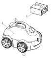
Fig. 1 is a structure diagram of a swimming pool bottom hydraulic pushed automatic cleaner; -
Fig. 2 is a structure diagram of an underwater cleaner; -
Fig. 3 is a structure diagram of a housing cover; -
Fig. 4 is a structure diagram of a housing body; -
Fig. 5 is a structure diagram of a filter; -
Fig. 6 is a structure diagram of a hydraulic driven jaw-type clutch impeller combination; -
Fig. 7 is a structure diagram of a water inlet/outlet flow passage; -
Fig. 8 is a structure diagram of a wheel and bracket; -
Fig. 9 is a structure diagram of a cable with floater; -
Fig. 10 is a structure diagram of a control power supply shown inFig. 1 ; -
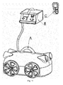
Fig. 11 is a structure diagram of a pool bottom automatic cleaner with turning function; -
Fig. 12 is a structure diagram of an underwater cleaner with turning function, -
Fig. 13 is a structure diagram of a control power supply shown inFig. 11 ; and -
Fig. 14 is a structure diagram of a remote controller shown inFig. 11 ;
in which:- 1. underwater cleaner, 2. control power supply; 11. housing cover part;
- 12. housing body part; 13. filter; 14. double extension shaft motor assembly;
- 15. hydraulic driven jaw-type clutch impeller combination; 16. water inlet/outlet flow passage;
- 17. wheel and bracket; 18. isolated hood; 19. cable with floater;
- 111. housing cover; 112. lock catch; 121. housing body;
- 122. one-way water inlet valve; 123. suction pipe; 124. one-way drain valve;
- 125. deflection member; 131. filter bracket; 132. filter bag;
- 151. impeller; 152. shaft sleeve; 161. flow passage;
- 162. flow guide cover; 163. swinging cap; 171. wheel;
- 172. bracket; 191. cable; 192. floater;
- 21. 12V AC power supply; 22. control circuit; 23. chassis;
- A. underwater cleaner with turning function; B. control power supply;
- C. remote controller; A1. housing cover part; A2. housing body part;
- A3. filter; Horizontally and in parallel arranged axial-flow pump set; A5. isolated hood;
- A6. cable with floater; B1. 12V AC power supply; B2, control circuit;
- B3. communication circuit; B4. chassis; C1. communication circuit;
- C2. battery; C3. housing
- As shown in
Fig. 1 to Fig. 10 , the swimming pool bottom hydraulic pushed automatic cleaner comprises theunderwater cleaner 1 and thecontrol power supply 2. Theunderwater cleaner 1 is composed of thehousing cover part 11, thehousing body part 12, the filter 13, the double extensionshaft motor assembly 14, the hydraulic driven jaw-type clutch impeller combination 15, the water inlet/outlet flow passage 16, the wheel andbracket 17, theisolated hood 18 and the cable with floater; 19. - The
housing cover part 11 comprises thehousing cover 111 and thelock catch 112. The double extensionshaft motor assembly 14 and the water inlet/outlet flow passage 16 are installed on the top inside thehousing cover part 111, and the center line of the front and back water inlet/outlet flow passage 16 is coaxial with the double extensionshaft motor assembly 14. Thelock catch 112 is a connecting lock for hermetically connecting thehousing cover 111 and thehousing body 121 top conveniently engage and disengage the housing cover and the housing body. Thehousing body part 12 comprises thehousing body 121, the one-waywater inlet valve 122, thesuction pipe 123, the one-way drain valve 124 and thedeflection member 125. Thehousing body 121 is a lower shell of theunderwater cleaner 1, the one-waywater inlet valve 122 and foursuction pipes 123 are arranged at the bottom, the one-way drain valve 124 is arranged on the lower portion side, and the cover plate of the valve is an elastic silica gel plate. The one-waywater inlet valve 122 is a water inlet of the axial-flow pump of the underwater cleaner, when the pump works, the one-waywater inlet valve 122 is sucked open, water containing sewage is sucked into the filter 13, and when the pump does not work, the one-waywater inlet valve 122 is automatically shut off to prevent the sewage within the filter 13 from flowing back. Thesuction pipe 123, the orifice of which is funnel-shaped, is extracted from the front and rear ends at the bottom of thehousing body 121, and extended under the leading and trailing edges of the underwater cleaner to prevent theunderwater cleaner 1 from disturbing and diffusing the sewage at the pool bottom. The one-way drain valve 124 is used for discharging the water within the housing when theunderwater cleaner 1 rises from water to reduce the weight when taken out from water. Thedeflection member 125 is an adjustment feeler lever arranged in the leading of thehousing cover 111, after automatically adjusting the direction when the leading edge of theunderwater cleaner 1 touches the pool wall, the longitudinal axis of theunderwater cleaner 1 and the pool wall form an included angle which is not 90 degrees, and it is not separated from the pool wall vertically when traveling in an opposite direction; the trailing edge of theunderwater cleaner 1 is not provided with thedeflection member 125, after automatically adjusting the direction when the trailing edge touches the pool wall, it is separated from the pool wall vertically. The housing cover is an upper shell of the underwater cleaner, the double extension shaft motor assembly is fixedly installed in the top center of the housing cover, and the inlet/outlet flow passage is fixedly installed at the front and back outlet. The filter 13 comprises afilter bracket 131 and afilter bag 132; the sewage in the pool water within the housing body is trapped, the clean water flowing through the filter 13 is discharged out of theunderwater cleaner 1 via the axial-flow pump, the filter is installed at the bottom of thehousing body 121, and the one-waywater inlet valve 122 and thesuction pipe 123 are within the filter 13. The double extensionshaft motor assembly 14 is a watertight 12V AC motor with double extension shaft, the shell of which is made of metal material, which directly works in the water, with good radiating conditions. - The hydraulic driven jaw-type clutch impeller combination 15 is composed of the
impeller 151 with sharp teeth on the end surface of the hub and theshaft sleeve 152 with sharp teeth on the end surface, the two end surfaces with sharp teeth where theimpeller 151 is connected with theshaft sleeve 152 are a pair of meshing surfaces. Theshaft sleeve 152 is fixed in the root of the outrigger shaft of the double extensionshaft motor assembly 14; theimpeller 151 is sleeved on the end portion of the outrigger shaft, and axially slideable and rotatable. The impeller and the shaft sleeve constitute a pair of jaw-type clutches. When theunderwater cleaner 1 works, along with the changing of the rotating direction of the motor, the impeller combination 15 can be automatically engaged and disengaged under the action of hydraulic power to change the working state of the impeller. The hydraulic driven jaw-type clutch impeller combination is characterized in that along with the changing of the rotating direction of the motor, the impeller combination can be automatically engaged and disengaged under the action of hydraulic power to change the working state of the impeller, and at the same time to change the travel direction of the underwater cleaner under the action of hydraulic power. When the motor rotates in the forward direction, the impeller is in a working state. A motor shaft drives the water between the impeller hub and the shaft to rotate, under the friction force of water, the impeller is made to rotate in the same direction. At this moment, the impeller is under the action of hydraulic power on the impeller surface. The end surface with sharp teeth of the impeller slides to the sleeve and directly meshes with the end surface of the sleeve to automatically enter a working state. When the motor rotates in the reverse direction, the friction force of water between the motor shaft and the impeller hub makes the impeller rotate in the reverse direction. At this moment, the impeller is under the action of hydraulic power on the impeller surface. The end surface with sharp teeth of the impeller slides far from the sleeve until it is disengaged from the sleeve to disengage the jaw-type clutch, and the impeller automatically enters a non-working state. Identical impeller components are respectively installed on the two outrigger shafts of the double extension shaft motor. When the motor rotates, although the number of the double extension shaft is one, the rotation direction of the motor is judged with respect to the shaft end, therefore, the impeller on the outrigger shaft of the motor always keeps opposite rotation direction, that is, the impeller on one end is in the working state, while the impeller on the other end has to be in the non-working state. The underwater cleaner travels towards the other end under the action of hydraulic power of the impeller on the working end. - The water inlet/outlet flow passage 16 comprises the flow passage, 161, the
flow guide cover 162 and the swingingcap 163. Theflow passage 161 is the water inlet/outlet flow passage of the axial-flow pump. When the flow rate increases and the pressure rises within theflow passage 161, the pressured water is ejected from the water outlet to push the underwater cleaner to travel in the reverse direction. Theflow guide cover 162 is located at the water outlet of the flow passage to eliminate the rotation of water flow at the water outlet and simultaneously prevent the entry of external substances. The swingingcap 163 is a water outlet cover plate which can turn outward. When theimpeller 151 is in the working state, the water flow ejected from the water outlet flow passage orifice automatically opens the swingingcap 163. When theimpeller 151 is in the non-working state, no water is discharged. The swinging cap automatically covers the water outlet under the action of its own weight torque to prevent the pool water from entering theunderwater cleaner 1. The wheel andbracket 17 is a traveling member of the underwater cleaner, comprising fourwheels 171 andbrackets 172. Thebrackets 172 are installed on thehousing body 121. Thewheels 171 are installed on stub shafts of thebrackets 172 and easily rotate on the stub shafts. Theisolated hood 18 is placed between the filter 13 and the double extensionshaft motor assembly 14 and installed on thehousing cover 111 to prevent the filter bag from being sucked into the axial-flow pump and also to prevent operators from touching the axial-flow pump by hands. The cable withfloater 19 comprises thecable 191 and thefloater 192, and is a connecting line of theunderwater cleaning water 1 and thecontrol power supply 2. Thecable 191 inputs a 12V AC current and a control signal to theunderwater cleaning water 1. Thefloater 192 provides buoyancy force for the cable to prevent the cable from sinking to the bottom of the pool to stop the traveling of theunderwater cleaning water 1. Thecontrol power supply 2, which supplies power for and controls theunderwater cleaning water 1, comprises the 12VAC power supply 21, thecontrol circuit 22 and thechassis 23. - As shown in
Fig. 2 , thehousing cover part 11, Thehousing body part 12, the double extensionshaft motor assembly 14, the hydraulic driven jaw-type clutch impeller combination 15, the water inlet/outlet flow passage 16 and thecable 19 constitute an axial-flow pump with double water injection nozzle. Thehousing cover part 11 and thehousing body part 12 constitute an axial-flow pump shell. The one-waywater inlet valve 122 at the bottom of thehousing body part 12 is a water inlet of the axial-flow pump. Two water inlet/outlet flow passage 16 are installed on thehousing cover 111, and the water outlet flow passage orifices of the flow passages are two water outlets of the axial-flow pump. The double extensionshaft motor assembly 14 is a power part of the axial-flow pump, installed on thehousing body 121. The axis of the motor is coaxial with the axis of two water inlet flow passages. Two hydraulic driven jaw-type clutch impeller combinations 15 are respectively installed on the outrigger shafts on both ends of themotor assembly 14. Theshaft sleeve 152 is fixed in the root of the outrigger shaft of the motor. Theimpeller 151 is sleeved on the end of the outrigger shaft of the motor, and slideable on the shaft. When the outrigger shaft of themotor assembly 14 rotates, the impeller combination 15 deflects according to the motor. When the impeller combination 15 on one end is engaged, the impeller is in the working state. When the impeller combination 15 on the other end is disengaged, the impeller is in the non-working state. When themotor assembly 14 is working, the impeller on one end works. The water under thehousing body 121 is sucked into thehousing body 121 via the one-waywater inlet valve 122 and is ejected from the water outlet of the water inlet/outlet flow passage 16 corresponding to the working impeller combination 15. When the motor changes the rotation direction, the other impeller combination 15 works. The water is ejected from the water outlet of the water inlet/outlet flow passage, 16 corresponding thereto, thereby realizing the axial-flow pump with double water injection nozzle. - As shown in
Fig. 11 to Fig. 14 , a swimming pool bottom hydraulic pushed automatic cleaner with turning function comprises the underwater cleaner with turning function A, the control power supply B and the remote controller C. The underwater cleaner with turning function A is formed in a way that, based on the technical scheme of theunderwater cleaner 1 ofEmbodiment 1, two or more double extensionshaft motor assemblies 14 are arranged horizontally and parallel to form two or more horizontally and parallel arranged axial-flow pump sets A4 with corresponding water inlet/outlet flow passage 16 and the hydraulic driven jaw-type clutch impeller combination 15. When theimpellers 151 on the same ends in the axial-flow pump sets A4 are working at the same time, the underwater cleaner with turning function travels along a straight line. When only oneimpeller 151 is working or theimpellers 151 on both ends of the horizontally and in parallel arranged axial-flow pump sets A4 are working alternatively, the underwater cleaner with turning function A travels in a circling or turning manner, with turning and maneuvering functions. The bottom of the swimming pool can be subjected to orderly complete coverage cleaning according to the set cleaning route. - The control power supply B comprises the 12V AC power supply B1, the control circuit B2, the communication circuit B3 and the chassis B4. The control power supply B supplies power for and controls the procedure of the swimming pool bottom hydraulic pushed automatic cleaner with turning function.
- The remote controller C, which remotely controls the cleaner, comprises the communication circuit C1, the battery C2 and the housing C3.
- The underwater cleaner with turning function A can perform orderly complete coverage cleaning for the bottom of the swimming pool according to the set procedure and operation instructions from the remote controller C.
Claims (10)
- A hydraulic driven jaw-type clutch impeller combination, comprising an impeller with sharp teeth on an end surface of a hub and a shaft sleeve with sharp teeth on an end surface, the two end surfaces with sharp teeth being a pair of meshing surfaces, wherein the shaft sleeve is fixed in the root of an outrigger shaft of a double extension shaft motor assembly; the impeller is sleeved on the end portion of the outrigger shaft; the impeller is axially slideable and rotatable; the impeller and the shaft sleeve constitute a pair of jaw-type clutches; along with the changing of the rotating direction of a motor, the impeller and the shaft sleeve are reliably engaged and disengaged under the action of hydraulic power to change the working state of the impeller.
- A swimming pool bottom hydraulic pushed automatic cleaner comprising the hydraulic driven jaw-type clutch impeller combination according to claim 1, comprising an underwater cleaner and a control power supply, which are connected together by a cable, wherein:the underwater cleaner comprises a housing cover part, a housing body part, a filter, a double extension shaft motor assembly, a hydraulic driven jaw-type clutch impeller combination, a water inlet/outlet flow passage, a wheel and bracket, an isolated hood and a cable;wherein the housing cover part, the housing body part, the double extension shaft motor assembly, the hydraulic driven jaw-type clutch impeller combination, the water inlet/outlet flow passage and the cable constitute an axial-flow pump with double water injection nozzle; both ends of the motor of the double extension shaft motor assembly are provided with outrigger shafts; the motor is watertight; the hydraulic driven jaw-type clutch impeller combination is installed on the outrigger shaft of the double extension shaft motor assembly;the water inlet/outlet flow passage comprises a flow passage, a flow guide cover and a swinging cap; the water inlet/outlet flow passage is a water inlet/outlet channel, with a water inlet in the front end and a water outlet in the tail end;the housing cover part comprises a housing cover and a lock catch;the housing body part comprises a housing body, a one-way water inlet valve, a suction pipe, a one-way drain valve and a deflection member; the housing cover and the housing body are hermetically connected with each other through the lock catch; the one-way water inlet valve is arranged at the bottom of the housing body; the suction pipe is extracted from the front and rear ends at the bottom of the housing body, and extended under the leading and trailing edges of the underwater cleaner; the deflection member is an adjustment feeler lever arranged in the leading edge of the housing cover;the filter comprises a filter bracket and a filter bag; the filter is installed at the bottom of the housing body; the one-way water inlet valve and the upper end of the suction pipe are arranged within the filter;the wheel and the bracket is fixedly installed on the side of the housing body;the isolated hood is placed between the filter and the double extension shaft motor assembly and installed on the housing cover;the control power supply comprises a power supply, a control circuit and a chassis.
- The swimming pool bottom hydraulic pushed automatic cleaner according to claim 2, wherein the number of the double extension shaft motor assembly is two, the two assemblies are arranged in parallel, and provided with four water outlet injection nozzles in total; the automatic cleaner also comprises a remote controller, which performs wireless remote control on the cleaner and comprises a communication circuit, a battery and a housing.
- The swimming pool bottom hydraulic pushed automatic cleaner according to claim 2 or 3, wherein the power supply is a 12V AC power supply.
- The swimming pool bottom hydraulic pushed automatic cleaner according to claim 2, 3 or 4, wherein a motor shell is made of metal material.
- The swimming pool bottom hydraulic pushed automatic cleaner according to claim 2, 3 or 4, wherein the cable is a buoyancy cable, which comprises a cable and floaters.
- The swimming pool bottom hydraulic pushed automatic cleaner according to claim 2, 3 or 4, wherein the suction pipe is arranged in the front end and the rear end at the bottom of the underwater cleaner; the ends of the suction pipe are under the leading and trailing edges of the housing; the orifice of the suction pipe is funnel-shaped.
- The swimming pool bottom hydraulic pushed automatic cleaner according to claim 5, wherein the suction pipe is arranged in the front end and the rear end at the bottom of the underwater cleaner; the ends of the suction pipe are under the leading and trailing edges of the housing; the orifice of the suction pipe is funnel-shaped.
- The swimming pool bottom hydraulic pushed automatic cleaner according to claim 2, 3 or 4, wherein the one-way drain valve is arranged on the lower portion of the housing body side, and the cover plate of the valve is an elastic silica gel plate.
- The swimming pool bottom hydraulic pushed automatic cleaner according to claim 5, wherein the one-way drain valve is arranged on the lower portion of the housing body side, and the cover plate of the valve is an elastic silica gel plate.
Applications Claiming Priority (3)
| Application Number | Priority Date | Filing Date | Title |
|---|---|---|---|
| CN 200910177497 CN101666168B (en) | 2009-09-30 | 2009-09-30 | Swimming pool bottom hydro power pushed automatic cleaner |
| CN 200920217844 CN201664686U (en) | 2009-09-30 | 2009-09-30 | Liquamatic tooth-embedded clutch impeller combination and swimming-pool bottom hydraulic-pushing automatic cleaning machine with combination |
| PCT/CN2010/074662 WO2011038602A1 (en) | 2009-09-30 | 2010-06-29 | Automatic cleaning machine driven by hydraulic power from bottom of swimming pool and hydraulic drive jaw type clutch impeller combination thereof |
Publications (3)
| Publication Number | Publication Date |
|---|---|
| EP2484847A1 true EP2484847A1 (en) | 2012-08-08 |
| EP2484847A4 EP2484847A4 (en) | 2013-07-03 |
| EP2484847B1 EP2484847B1 (en) | 2016-04-27 |
Family
ID=43825526
Family Applications (1)
| Application Number | Title | Priority Date | Filing Date |
|---|---|---|---|
| EP10819831.8A Active EP2484847B1 (en) | 2009-09-30 | 2010-06-29 | Automatic cleaning machine with a hydraulic drive jaw type clutch impeller combination |
Country Status (5)
| Country | Link |
|---|---|
| US (1) | US8555445B2 (en) |
| EP (1) | EP2484847B1 (en) |
| AU (1) | AU2010302872B8 (en) |
| ES (1) | ES2575219T3 (en) |
| WO (1) | WO2011038602A1 (en) |
Cited By (5)
| Publication number | Priority date | Publication date | Assignee | Title |
|---|---|---|---|---|
| EP3023561A1 (en) * | 2014-11-24 | 2016-05-25 | Upward Sales Limited | Jet propelled pool cleaner |
| EP2971409A4 (en) * | 2013-03-14 | 2016-12-07 | Hayward Ind Inc | Pool cleaner drive mechanism and associated systems and methods |
| WO2017060588A2 (en) | 2015-10-05 | 2017-04-13 | Max Roumagnac | Autonomous pool cleaning robot |
| US9677294B2 (en) | 2013-03-15 | 2017-06-13 | Hayward Industries, Inc. | Pool cleaning device with wheel drive assemblies |
| US9856669B2 (en) | 2014-11-24 | 2018-01-02 | Compurobot Technology Company | Advanced pool cleaner construction |
Families Citing this family (22)
| Publication number | Priority date | Publication date | Assignee | Title |
|---|---|---|---|---|
| ES2718604T3 (en) | 2010-02-11 | 2019-07-03 | Aqua Products Inc | Water jet pool cleaner with opposite double propellers |
| FR2981970B1 (en) * | 2011-10-27 | 2013-11-29 | Zodiac Pool Care Europe | IMMEREDE SURFACE CLEANER APPARATUS WITH SEMI-AUTOMATIC RETURN CONTROL |
| EP2929109B1 (en) * | 2012-09-04 | 2018-01-10 | Pentair Water Pool and Spa, Inc. | Pool cleaner generator module with magnetic coupling |
| US20140137343A1 (en) * | 2012-11-20 | 2014-05-22 | Aqua Products, Inc. | Pool or tank cleaning vehicle with a powered brush |
| ES2900654T3 (en) | 2013-03-15 | 2022-03-17 | Hayward Ind Inc | Modular pool/whirlpool control system |
| CN105019498A (en) * | 2014-04-21 | 2015-11-04 | 中国石油化工股份有限公司 | Intelligent machine for removing sludge of floating pontoon |
| US9885196B2 (en) | 2015-01-26 | 2018-02-06 | Hayward Industries, Inc. | Pool cleaner power coupling |
| ES2770925T3 (en) | 2015-03-23 | 2020-07-03 | Aqua Products Inc | Self-propelled robotic pool cleaner with pressure wash assembly to lift debris from a surface underneath the pool cleaner |
| EP4343457A2 (en) | 2016-01-22 | 2024-03-27 | Hayward Industries, Inc. | Systems and methods for providing network connectivity and remote monitoring, optimization, and control of pool/spa equipment |
| US11720085B2 (en) | 2016-01-22 | 2023-08-08 | Hayward Industries, Inc. | Systems and methods for providing network connectivity and remote monitoring, optimization, and control of pool/spa equipment |
| CN205713278U (en) * | 2016-06-29 | 2016-11-23 | 淮安普乐菲智能科技有限公司 | A kind of underwater cleaning robot |
| US10407931B2 (en) | 2016-09-02 | 2019-09-10 | Aqua Products, Inc. | Modular swimming pool cleaner |
| US10676950B2 (en) | 2017-05-11 | 2020-06-09 | Hayward Industries, Inc. | Pool cleaner roller latch |
| US9885194B1 (en) * | 2017-05-11 | 2018-02-06 | Hayward Industries, Inc. | Pool cleaner impeller subassembly |
| CN109424223A (en) * | 2017-08-28 | 2019-03-05 | 宁波市普世达泳池用品有限公司 | A kind of water energy cleaner |
| CN107700885B (en) * | 2017-09-19 | 2023-05-23 | 明达实业(厦门)有限公司 | Pool cleaner |
| CN116927555A (en) * | 2018-04-28 | 2023-10-24 | 天津望圆智能科技股份有限公司 | Touch wall detection device of underwater cleaner and underwater cleaner |
| CN109653547B (en) * | 2018-12-28 | 2024-02-20 | 广州蓝海机器人系统有限公司 | Submersible cleaning machine and cleaning method |
| US10774557B1 (en) | 2019-02-21 | 2020-09-15 | Aquatron Robotic Technology Ltd. | Pool cleaner with selective inlet control |
| USD945723S1 (en) * | 2020-07-09 | 2022-03-08 | Aquastar Pool Products, Inc. | Pool cleaner |
| CN113830847B (en) * | 2021-09-29 | 2023-03-21 | 中清生态环境(宁波)有限公司 | Multifunctional water body purifying ship |
| CN114876250B (en) * | 2022-05-31 | 2023-09-19 | 广州城市理工学院 | Moving method of underwater cleaning equipment |
Citations (2)
| Publication number | Priority date | Publication date | Assignee | Title |
|---|---|---|---|---|
| CN101101005A (en) * | 2007-07-31 | 2008-01-09 | 施连孔 | Directional rotating immersible pump |
| FR2925555A1 (en) * | 2007-12-21 | 2009-06-26 | Zodiac Pool Care Europ Soc Par | IMMERSE SURFACE CLEANING APPARATUS WITH EASY DRAIN |
Family Cites Families (5)
| Publication number | Priority date | Publication date | Assignee | Title |
|---|---|---|---|---|
| JPH0528921A (en) | 1991-07-18 | 1993-02-05 | Hitachi Ltd | Focusing method of camera |
| JP2977663B2 (en) * | 1992-04-14 | 1999-11-15 | サンデン株式会社 | Underwater vacuum cleaner |
| JP3281516B2 (en) * | 1995-08-07 | 2002-05-13 | 確太郎 福田 | Aquarium purifier |
| US7118632B2 (en) * | 2004-05-26 | 2006-10-10 | Aqua-Vac Systems, Inc. | Pool cleaning method and device |
| CN101666168B (en) * | 2009-09-30 | 2011-01-12 | 付桂兰 | Swimming pool bottom hydro power pushed automatic cleaner |
-
2010
- 2010-06-29 US US13/499,551 patent/US8555445B2/en active Active
- 2010-06-29 EP EP10819831.8A patent/EP2484847B1/en active Active
- 2010-06-29 ES ES10819831.8T patent/ES2575219T3/en active Active
- 2010-06-29 WO PCT/CN2010/074662 patent/WO2011038602A1/en active Application Filing
- 2010-06-29 AU AU2010302872A patent/AU2010302872B8/en active Active
Patent Citations (2)
| Publication number | Priority date | Publication date | Assignee | Title |
|---|---|---|---|---|
| CN101101005A (en) * | 2007-07-31 | 2008-01-09 | 施连孔 | Directional rotating immersible pump |
| FR2925555A1 (en) * | 2007-12-21 | 2009-06-26 | Zodiac Pool Care Europ Soc Par | IMMERSE SURFACE CLEANING APPARATUS WITH EASY DRAIN |
Non-Patent Citations (1)
| Title |
|---|
| See also references of WO2011038602A1 * |
Cited By (7)
| Publication number | Priority date | Publication date | Assignee | Title |
|---|---|---|---|---|
| EP2971409A4 (en) * | 2013-03-14 | 2016-12-07 | Hayward Ind Inc | Pool cleaner drive mechanism and associated systems and methods |
| US9677294B2 (en) | 2013-03-15 | 2017-06-13 | Hayward Industries, Inc. | Pool cleaning device with wheel drive assemblies |
| EP3023561A1 (en) * | 2014-11-24 | 2016-05-25 | Upward Sales Limited | Jet propelled pool cleaner |
| US9856669B2 (en) | 2014-11-24 | 2018-01-02 | Compurobot Technology Company | Advanced pool cleaner construction |
| WO2017060588A2 (en) | 2015-10-05 | 2017-04-13 | Max Roumagnac | Autonomous pool cleaning robot |
| US10370865B2 (en) | 2015-10-05 | 2019-08-06 | Kokido Development Limited | Autonomous pool cleaning robot |
| US10895086B2 (en) | 2015-10-05 | 2021-01-19 | Kokido Development Limited | Autonomous pool cleaning robot |
Also Published As
| Publication number | Publication date |
|---|---|
| AU2010302872A8 (en) | 2014-10-30 |
| EP2484847A4 (en) | 2013-07-03 |
| WO2011038602A1 (en) | 2011-04-07 |
| US20120279001A1 (en) | 2012-11-08 |
| AU2010302872B2 (en) | 2014-10-16 |
| US8555445B2 (en) | 2013-10-15 |
| EP2484847B1 (en) | 2016-04-27 |
| AU2010302872B8 (en) | 2014-10-30 |
| AU2010302872A2 (en) | 2012-05-31 |
| ES2575219T3 (en) | 2016-06-27 |
| AU2010302872A1 (en) | 2012-05-17 |
Similar Documents
| Publication | Publication Date | Title |
|---|---|---|
| US8555445B2 (en) | Hydraulic driven jaw-type clutch impeller combination and swimming pool bottom hydraulic pushed automatic cleaner comprising same | |
| CN101666168B (en) | Swimming pool bottom hydro power pushed automatic cleaner | |
| US11359398B2 (en) | Turbine-driven swimming pool cleaning apparatus | |
| AU2002252660B2 (en) | Electric powered automatic swimming pool cleaning system | |
| US20140251884A1 (en) | Apparatus for cleaning an immersed surface having a single reversible electric driving and pumping motor | |
| JPH0947735A (en) | Water tank purifier | |
| WO2014070301A1 (en) | Turbine-driven swimming pool cleaning apparatus and method | |
| EP3303733B1 (en) | System of pool cleaner and docking station in a pool | |
| CN110080379B (en) | Small-size sewer bottom rubbish clean out equipment | |
| CN109339010A (en) | It is a kind of for clearing up the cleaning auxiliary device of garbage floating on water surface | |
| CN215855446U (en) | A treatment facility for PTFE waste water | |
| CN205444273U (en) | Portable submarine soil pick -up car | |
| CN111305370A (en) | Pipeline dredging device for housekeeping service | |
| CN217782187U (en) | Novel hydraulic engineering desilting device | |
| CN201664686U (en) | Liquamatic tooth-embedded clutch impeller combination and swimming-pool bottom hydraulic-pushing automatic cleaning machine with combination | |
| EP3643840A2 (en) | Device for cleaning the bottom of water-holding spaces | |
| US20110088725A1 (en) | Guide device for an automatic device for cleaning a surface immersed in a liquid | |
| CN207822650U (en) | A kind of cleaner for filter element | |
| CN206867807U (en) | A kind of warship marine seawater filter | |
| CN110584539A (en) | Cleaning robot | |
| CN219502252U (en) | Multistage dust collector is used in cotton processing of blending | |
| EP4306020A1 (en) | Device structure for automatically opening and closing wastewater tank valve of cleaning machine | |
| CN216893608U (en) | Building glass curtain wall cleaning device | |
| CN212731314U (en) | A grit chamber sand removal device for domestic sewage handles | |
| JPH07328579A (en) | Water tank cleaning machine |
Legal Events
| Date | Code | Title | Description |
|---|---|---|---|
| PUAI | Public reference made under article 153(3) epc to a published international application that has entered the european phase |
Free format text: ORIGINAL CODE: 0009012 |
|
| 17P | Request for examination filed |
Effective date: 20120330 |
|
| AK | Designated contracting states |
Kind code of ref document: A1 Designated state(s): AL AT BE BG CH CY CZ DE DK EE ES FI FR GB GR HR HU IE IS IT LI LT LU LV MC MK MT NL NO PL PT RO SE SI SK SM TR |
|
| DAX | Request for extension of the european patent (deleted) | ||
| A4 | Supplementary search report drawn up and despatched |
Effective date: 20130531 |
|
| RIC1 | Information provided on ipc code assigned before grant |
Ipc: E04H 4/16 20060101AFI20130524BHEP Ipc: B08B 1/00 20060101ALI20130524BHEP Ipc: B01D 35/02 20060101ALI20130524BHEP |
|
| 17Q | First examination report despatched |
Effective date: 20140205 |
|
| GRAP | Despatch of communication of intention to grant a patent |
Free format text: ORIGINAL CODE: EPIDOSNIGR1 |
|
| INTG | Intention to grant announced |
Effective date: 20151217 |
|
| GRAS | Grant fee paid |
Free format text: ORIGINAL CODE: EPIDOSNIGR3 |
|
| GRAA | (expected) grant |
Free format text: ORIGINAL CODE: 0009210 |
|
| AK | Designated contracting states |
Kind code of ref document: B1 Designated state(s): AL AT BE BG CH CY CZ DE DK EE ES FI FR GB GR HR HU IE IS IT LI LT LU LV MC MK MT NL NO PL PT RO SE SI SK SM TR |
|
| REG | Reference to a national code |
Ref country code: GB Ref legal event code: FG4D |
|
| REG | Reference to a national code |
Ref country code: CH Ref legal event code: EP |
|
| REG | Reference to a national code |
Ref country code: AT Ref legal event code: REF Ref document number: 795006 Country of ref document: AT Kind code of ref document: T Effective date: 20160515 |
|
| REG | Reference to a national code |
Ref country code: IE Ref legal event code: FG4D |
|
| REG | Reference to a national code |
Ref country code: DE Ref legal event code: R096 Ref document number: 602010032918 Country of ref document: DE |
|
| REG | Reference to a national code |
Ref country code: ES Ref legal event code: FG2A Ref document number: 2575219 Country of ref document: ES Kind code of ref document: T3 Effective date: 20160627 Ref country code: FR Ref legal event code: PLFP Year of fee payment: 7 |
|
| REG | Reference to a national code |
Ref country code: LT Ref legal event code: MG4D |
|
| REG | Reference to a national code |
Ref country code: NL Ref legal event code: MP Effective date: 20160427 |
|
| PG25 | Lapsed in a contracting state [announced via postgrant information from national office to epo] |
Ref country code: NL Free format text: LAPSE BECAUSE OF FAILURE TO SUBMIT A TRANSLATION OF THE DESCRIPTION OR TO PAY THE FEE WITHIN THE PRESCRIBED TIME-LIMIT Effective date: 20160427 |
|
| PG25 | Lapsed in a contracting state [announced via postgrant information from national office to epo] |
Ref country code: LT Free format text: LAPSE BECAUSE OF FAILURE TO SUBMIT A TRANSLATION OF THE DESCRIPTION OR TO PAY THE FEE WITHIN THE PRESCRIBED TIME-LIMIT Effective date: 20160427 Ref country code: PL Free format text: LAPSE BECAUSE OF FAILURE TO SUBMIT A TRANSLATION OF THE DESCRIPTION OR TO PAY THE FEE WITHIN THE PRESCRIBED TIME-LIMIT Effective date: 20160427 Ref country code: NO Free format text: LAPSE BECAUSE OF FAILURE TO SUBMIT A TRANSLATION OF THE DESCRIPTION OR TO PAY THE FEE WITHIN THE PRESCRIBED TIME-LIMIT Effective date: 20160727 Ref country code: FI Free format text: LAPSE BECAUSE OF FAILURE TO SUBMIT A TRANSLATION OF THE DESCRIPTION OR TO PAY THE FEE WITHIN THE PRESCRIBED TIME-LIMIT Effective date: 20160427 |
|
| PG25 | Lapsed in a contracting state [announced via postgrant information from national office to epo] |
Ref country code: SE Free format text: LAPSE BECAUSE OF FAILURE TO SUBMIT A TRANSLATION OF THE DESCRIPTION OR TO PAY THE FEE WITHIN THE PRESCRIBED TIME-LIMIT Effective date: 20160427 Ref country code: HR Free format text: LAPSE BECAUSE OF FAILURE TO SUBMIT A TRANSLATION OF THE DESCRIPTION OR TO PAY THE FEE WITHIN THE PRESCRIBED TIME-LIMIT Effective date: 20160427 Ref country code: PT Free format text: LAPSE BECAUSE OF FAILURE TO SUBMIT A TRANSLATION OF THE DESCRIPTION OR TO PAY THE FEE WITHIN THE PRESCRIBED TIME-LIMIT Effective date: 20160829 Ref country code: GR Free format text: LAPSE BECAUSE OF FAILURE TO SUBMIT A TRANSLATION OF THE DESCRIPTION OR TO PAY THE FEE WITHIN THE PRESCRIBED TIME-LIMIT Effective date: 20160728 Ref country code: LV Free format text: LAPSE BECAUSE OF FAILURE TO SUBMIT A TRANSLATION OF THE DESCRIPTION OR TO PAY THE FEE WITHIN THE PRESCRIBED TIME-LIMIT Effective date: 20160427 |
|
| PG25 | Lapsed in a contracting state [announced via postgrant information from national office to epo] |
Ref country code: BE Free format text: LAPSE BECAUSE OF FAILURE TO SUBMIT A TRANSLATION OF THE DESCRIPTION OR TO PAY THE FEE WITHIN THE PRESCRIBED TIME-LIMIT Effective date: 20160427 Ref country code: IT Free format text: LAPSE BECAUSE OF FAILURE TO SUBMIT A TRANSLATION OF THE DESCRIPTION OR TO PAY THE FEE WITHIN THE PRESCRIBED TIME-LIMIT Effective date: 20160427 |
|
| REG | Reference to a national code |
Ref country code: DE Ref legal event code: R097 Ref document number: 602010032918 Country of ref document: DE |
|
| PG25 | Lapsed in a contracting state [announced via postgrant information from national office to epo] |
Ref country code: EE Free format text: LAPSE BECAUSE OF FAILURE TO SUBMIT A TRANSLATION OF THE DESCRIPTION OR TO PAY THE FEE WITHIN THE PRESCRIBED TIME-LIMIT Effective date: 20160427 Ref country code: MC Free format text: LAPSE BECAUSE OF FAILURE TO SUBMIT A TRANSLATION OF THE DESCRIPTION OR TO PAY THE FEE WITHIN THE PRESCRIBED TIME-LIMIT Effective date: 20160427 Ref country code: SK Free format text: LAPSE BECAUSE OF FAILURE TO SUBMIT A TRANSLATION OF THE DESCRIPTION OR TO PAY THE FEE WITHIN THE PRESCRIBED TIME-LIMIT Effective date: 20160427 Ref country code: DK Free format text: LAPSE BECAUSE OF FAILURE TO SUBMIT A TRANSLATION OF THE DESCRIPTION OR TO PAY THE FEE WITHIN THE PRESCRIBED TIME-LIMIT Effective date: 20160427 Ref country code: CZ Free format text: LAPSE BECAUSE OF FAILURE TO SUBMIT A TRANSLATION OF THE DESCRIPTION OR TO PAY THE FEE WITHIN THE PRESCRIBED TIME-LIMIT Effective date: 20160427 Ref country code: RO Free format text: LAPSE BECAUSE OF FAILURE TO SUBMIT A TRANSLATION OF THE DESCRIPTION OR TO PAY THE FEE WITHIN THE PRESCRIBED TIME-LIMIT Effective date: 20160427 |
|
| REG | Reference to a national code |
Ref country code: CH Ref legal event code: PL |
|
| PG25 | Lapsed in a contracting state [announced via postgrant information from national office to epo] |
Ref country code: SM Free format text: LAPSE BECAUSE OF FAILURE TO SUBMIT A TRANSLATION OF THE DESCRIPTION OR TO PAY THE FEE WITHIN THE PRESCRIBED TIME-LIMIT Effective date: 20160427 |
|
| PLBE | No opposition filed within time limit |
Free format text: ORIGINAL CODE: 0009261 |
|
| STAA | Information on the status of an ep patent application or granted ep patent |
Free format text: STATUS: NO OPPOSITION FILED WITHIN TIME LIMIT |
|
| GBPC | Gb: european patent ceased through non-payment of renewal fee |
Effective date: 20160727 |
|
| REG | Reference to a national code |
Ref country code: IE Ref legal event code: MM4A |
|
| 26N | No opposition filed |
Effective date: 20170130 |
|
| PG25 | Lapsed in a contracting state [announced via postgrant information from national office to epo] |
Ref country code: LI Free format text: LAPSE BECAUSE OF NON-PAYMENT OF DUE FEES Effective date: 20160630 Ref country code: CH Free format text: LAPSE BECAUSE OF NON-PAYMENT OF DUE FEES Effective date: 20160630 |
|
| PG25 | Lapsed in a contracting state [announced via postgrant information from national office to epo] |
Ref country code: GB Free format text: LAPSE BECAUSE OF NON-PAYMENT OF DUE FEES Effective date: 20160727 Ref country code: IE Free format text: LAPSE BECAUSE OF NON-PAYMENT OF DUE FEES Effective date: 20160629 Ref country code: SI Free format text: LAPSE BECAUSE OF FAILURE TO SUBMIT A TRANSLATION OF THE DESCRIPTION OR TO PAY THE FEE WITHIN THE PRESCRIBED TIME-LIMIT Effective date: 20160427 |
|
| REG | Reference to a national code |
Ref country code: FR Ref legal event code: PLFP Year of fee payment: 8 |
|
| REG | Reference to a national code |
Ref country code: AT Ref legal event code: UEP Ref document number: 795006 Country of ref document: AT Kind code of ref document: T Effective date: 20160427 |
|
| PG25 | Lapsed in a contracting state [announced via postgrant information from national office to epo] |
Ref country code: CY Free format text: LAPSE BECAUSE OF FAILURE TO SUBMIT A TRANSLATION OF THE DESCRIPTION OR TO PAY THE FEE WITHIN THE PRESCRIBED TIME-LIMIT Effective date: 20160427 Ref country code: HU Free format text: LAPSE BECAUSE OF FAILURE TO SUBMIT A TRANSLATION OF THE DESCRIPTION OR TO PAY THE FEE WITHIN THE PRESCRIBED TIME-LIMIT; INVALID AB INITIO Effective date: 20100629 |
|
| REG | Reference to a national code |
Ref country code: FR Ref legal event code: PLFP Year of fee payment: 9 |
|
| PG25 | Lapsed in a contracting state [announced via postgrant information from national office to epo] |
Ref country code: LU Free format text: LAPSE BECAUSE OF NON-PAYMENT OF DUE FEES Effective date: 20160629 Ref country code: IS Free format text: LAPSE BECAUSE OF FAILURE TO SUBMIT A TRANSLATION OF THE DESCRIPTION OR TO PAY THE FEE WITHIN THE PRESCRIBED TIME-LIMIT Effective date: 20160427 Ref country code: TR Free format text: LAPSE BECAUSE OF FAILURE TO SUBMIT A TRANSLATION OF THE DESCRIPTION OR TO PAY THE FEE WITHIN THE PRESCRIBED TIME-LIMIT Effective date: 20160427 Ref country code: MK Free format text: LAPSE BECAUSE OF FAILURE TO SUBMIT A TRANSLATION OF THE DESCRIPTION OR TO PAY THE FEE WITHIN THE PRESCRIBED TIME-LIMIT Effective date: 20160427 Ref country code: MT Free format text: LAPSE BECAUSE OF NON-PAYMENT OF DUE FEES Effective date: 20160630 |
|
| PG25 | Lapsed in a contracting state [announced via postgrant information from national office to epo] |
Ref country code: BG Free format text: LAPSE BECAUSE OF FAILURE TO SUBMIT A TRANSLATION OF THE DESCRIPTION OR TO PAY THE FEE WITHIN THE PRESCRIBED TIME-LIMIT Effective date: 20160427 |
|
| PG25 | Lapsed in a contracting state [announced via postgrant information from national office to epo] |
Ref country code: AL Free format text: LAPSE BECAUSE OF FAILURE TO SUBMIT A TRANSLATION OF THE DESCRIPTION OR TO PAY THE FEE WITHIN THE PRESCRIBED TIME-LIMIT Effective date: 20160427 |
|
| REG | Reference to a national code |
Ref country code: DE Ref legal event code: R081 Ref document number: 602010032918 Country of ref document: DE Owner name: WYBOTICS CO., LTD., CN Free format text: FORMER OWNER: FU, GUILAN, TIANJIN, CN |
|
| REG | Reference to a national code |
Ref country code: ES Ref legal event code: PC2A Owner name: WYBOTICS CO., LTD. Effective date: 20220525 |
|
| REG | Reference to a national code |
Ref country code: AT Ref legal event code: PC Ref document number: 795006 Country of ref document: AT Kind code of ref document: T Owner name: WYBOTICS CO., LTD., CN Effective date: 20220503 |
|
| PGFP | Annual fee paid to national office [announced via postgrant information from national office to epo] |
Ref country code: FR Payment date: 20230531 Year of fee payment: 14 Ref country code: DE Payment date: 20230626 Year of fee payment: 14 |
|
| PGFP | Annual fee paid to national office [announced via postgrant information from national office to epo] |
Ref country code: AT Payment date: 20230627 Year of fee payment: 14 |
|
| PGFP | Annual fee paid to national office [announced via postgrant information from national office to epo] |
Ref country code: ES Payment date: 20230705 Year of fee payment: 14 |