EP2479720B1 - System and method for storing and monitoring goods using RFID technology - Google Patents
System and method for storing and monitoring goods using RFID technology Download PDFInfo
- Publication number
- EP2479720B1 EP2479720B1 EP12150220.7A EP12150220A EP2479720B1 EP 2479720 B1 EP2479720 B1 EP 2479720B1 EP 12150220 A EP12150220 A EP 12150220A EP 2479720 B1 EP2479720 B1 EP 2479720B1
- Authority
- EP
- European Patent Office
- Prior art keywords
- detected
- reading device
- goods
- rfid
- energy level
- Prior art date
- Legal status (The legal status is an assumption and is not a legal conclusion. Google has not performed a legal analysis and makes no representation as to the accuracy of the status listed.)
- Not-in-force
Links
Images

Classifications
-
- G—PHYSICS
- G06—COMPUTING; CALCULATING OR COUNTING
- G06Q—INFORMATION AND COMMUNICATION TECHNOLOGY [ICT] SPECIALLY ADAPTED FOR ADMINISTRATIVE, COMMERCIAL, FINANCIAL, MANAGERIAL OR SUPERVISORY PURPOSES; SYSTEMS OR METHODS SPECIALLY ADAPTED FOR ADMINISTRATIVE, COMMERCIAL, FINANCIAL, MANAGERIAL OR SUPERVISORY PURPOSES, NOT OTHERWISE PROVIDED FOR
- G06Q10/00—Administration; Management
- G06Q10/08—Logistics, e.g. warehousing, loading or distribution; Inventory or stock management
-
- B—PERFORMING OPERATIONS; TRANSPORTING
- B65—CONVEYING; PACKING; STORING; HANDLING THIN OR FILAMENTARY MATERIAL
- B65G—TRANSPORT OR STORAGE DEVICES, e.g. CONVEYORS FOR LOADING OR TIPPING, SHOP CONVEYOR SYSTEMS OR PNEUMATIC TUBE CONVEYORS
- B65G1/00—Storing articles, individually or in orderly arrangement, in warehouses or magazines
- B65G1/02—Storage devices
- B65G1/04—Storage devices mechanical
- B65G1/137—Storage devices mechanical with arrangements or automatic control means for selecting which articles are to be removed
-
- G—PHYSICS
- G06—COMPUTING; CALCULATING OR COUNTING
- G06K—GRAPHICAL DATA READING; PRESENTATION OF DATA; RECORD CARRIERS; HANDLING RECORD CARRIERS
- G06K7/00—Methods or arrangements for sensing record carriers, e.g. for reading patterns
- G06K7/10—Methods or arrangements for sensing record carriers, e.g. for reading patterns by electromagnetic radiation, e.g. optical sensing; by corpuscular radiation
- G06K7/10009—Methods or arrangements for sensing record carriers, e.g. for reading patterns by electromagnetic radiation, e.g. optical sensing; by corpuscular radiation sensing by radiation using wavelengths larger than 0.1 mm, e.g. radio-waves or microwaves
- G06K7/10019—Methods or arrangements for sensing record carriers, e.g. for reading patterns by electromagnetic radiation, e.g. optical sensing; by corpuscular radiation sensing by radiation using wavelengths larger than 0.1 mm, e.g. radio-waves or microwaves resolving collision on the communication channels between simultaneously or concurrently interrogated record carriers.
- G06K7/10079—Methods or arrangements for sensing record carriers, e.g. for reading patterns by electromagnetic radiation, e.g. optical sensing; by corpuscular radiation sensing by radiation using wavelengths larger than 0.1 mm, e.g. radio-waves or microwaves resolving collision on the communication channels between simultaneously or concurrently interrogated record carriers. the collision being resolved in the spatial domain, e.g. temporary shields for blindfolding the interrogator in specific directions
- G06K7/10089—Methods or arrangements for sensing record carriers, e.g. for reading patterns by electromagnetic radiation, e.g. optical sensing; by corpuscular radiation sensing by radiation using wavelengths larger than 0.1 mm, e.g. radio-waves or microwaves resolving collision on the communication channels between simultaneously or concurrently interrogated record carriers. the collision being resolved in the spatial domain, e.g. temporary shields for blindfolding the interrogator in specific directions the interrogation device using at least one directional antenna or directional interrogation field to resolve the collision
- G06K7/10099—Methods or arrangements for sensing record carriers, e.g. for reading patterns by electromagnetic radiation, e.g. optical sensing; by corpuscular radiation sensing by radiation using wavelengths larger than 0.1 mm, e.g. radio-waves or microwaves resolving collision on the communication channels between simultaneously or concurrently interrogated record carriers. the collision being resolved in the spatial domain, e.g. temporary shields for blindfolding the interrogator in specific directions the interrogation device using at least one directional antenna or directional interrogation field to resolve the collision the directional field being used for pinpointing the location of the record carrier, e.g. for finding or locating an RFID tag amongst a plurality of RFID tags, each RFID tag being associated with an object, e.g. for physically locating the RFID tagged object in a warehouse
-
- G—PHYSICS
- G06—COMPUTING; CALCULATING OR COUNTING
- G06K—GRAPHICAL DATA READING; PRESENTATION OF DATA; RECORD CARRIERS; HANDLING RECORD CARRIERS
- G06K7/00—Methods or arrangements for sensing record carriers, e.g. for reading patterns
- G06K7/10—Methods or arrangements for sensing record carriers, e.g. for reading patterns by electromagnetic radiation, e.g. optical sensing; by corpuscular radiation
- G06K7/10009—Methods or arrangements for sensing record carriers, e.g. for reading patterns by electromagnetic radiation, e.g. optical sensing; by corpuscular radiation sensing by radiation using wavelengths larger than 0.1 mm, e.g. radio-waves or microwaves
- G06K7/10316—Methods or arrangements for sensing record carriers, e.g. for reading patterns by electromagnetic radiation, e.g. optical sensing; by corpuscular radiation sensing by radiation using wavelengths larger than 0.1 mm, e.g. radio-waves or microwaves using at least one antenna particularly designed for interrogating the wireless record carriers
- G06K7/10356—Methods or arrangements for sensing record carriers, e.g. for reading patterns by electromagnetic radiation, e.g. optical sensing; by corpuscular radiation sensing by radiation using wavelengths larger than 0.1 mm, e.g. radio-waves or microwaves using at least one antenna particularly designed for interrogating the wireless record carriers using a plurality of antennas, e.g. configurations including means to resolve interference between the plurality of antennas
-
- G—PHYSICS
- G06—COMPUTING; CALCULATING OR COUNTING
- G06K—GRAPHICAL DATA READING; PRESENTATION OF DATA; RECORD CARRIERS; HANDLING RECORD CARRIERS
- G06K7/00—Methods or arrangements for sensing record carriers, e.g. for reading patterns
- G06K7/10—Methods or arrangements for sensing record carriers, e.g. for reading patterns by electromagnetic radiation, e.g. optical sensing; by corpuscular radiation
- G06K7/10009—Methods or arrangements for sensing record carriers, e.g. for reading patterns by electromagnetic radiation, e.g. optical sensing; by corpuscular radiation sensing by radiation using wavelengths larger than 0.1 mm, e.g. radio-waves or microwaves
- G06K7/10366—Methods or arrangements for sensing record carriers, e.g. for reading patterns by electromagnetic radiation, e.g. optical sensing; by corpuscular radiation sensing by radiation using wavelengths larger than 0.1 mm, e.g. radio-waves or microwaves the interrogation device being adapted for miscellaneous applications
- G06K7/10475—Methods or arrangements for sensing record carriers, e.g. for reading patterns by electromagnetic radiation, e.g. optical sensing; by corpuscular radiation sensing by radiation using wavelengths larger than 0.1 mm, e.g. radio-waves or microwaves the interrogation device being adapted for miscellaneous applications arrangements to facilitate interaction with further interrogation devices, e.g. such that at least two interrogation devices may function and cooperate in a network of such devices
-
- B—PERFORMING OPERATIONS; TRANSPORTING
- B65—CONVEYING; PACKING; STORING; HANDLING THIN OR FILAMENTARY MATERIAL
- B65G—TRANSPORT OR STORAGE DEVICES, e.g. CONVEYORS FOR LOADING OR TIPPING, SHOP CONVEYOR SYSTEMS OR PNEUMATIC TUBE CONVEYORS
- B65G2203/00—Indexing code relating to control or detection of the articles or the load carriers during conveying
- B65G2203/04—Detection means
- B65G2203/042—Sensors
- B65G2203/046—RFID
Description
Die Erfindung betrifft ein System zur Lagerung und Überwachung von Gütern, umfassend wenigstens eine Lagerebene, auf der die Güter an definierten Positionen platzierbar sind, so dass jedes Gut einer definierten Position zugeordnet ist. Jedes Gut ist dabei jeweils mit wenigstens einem passiven RFID-Transponder versehen, und das System umfasst wenigstens ein Lesegerät zur Erfassung dieser RFID-Transponder an den Gütern. Das wenigstens eine Lesegerät steht in Verbindung mit einer Datenverarbeitungseinheit, welche Mittel zur Auswertung erfasster RFID-Signale der RFID-Transponder aufweist, und jeder Lagerebene des Systems sind wenigstens zwei Lesegeräte zugeordnet, die Transponder auf der betreffenden Lagerebene erfassen können.The invention relates to a system for storage and monitoring of goods, comprising at least one storage level on which the goods can be placed at defined positions, so that each good is assigned to a defined position. Each good is in each case provided with at least one passive RFID transponder, and the system comprises at least one reader for detecting these RFID transponders on the goods. The at least one reading device is connected to a data processing unit, which has means for evaluating detected RFID signals of the RFID transponders, and each storage level of the system is assigned at least two readers, which can detect transponders on the relevant storage level.
Die Erfindung betrifft ferner ein Verfahren zur Überwachung von Gütern in einem solchen System, bei dem die Auswertung der RFID-Signale durch die Datenverarbeitungseinheit eine Zuordnung von RFID-Transpondern und den ihnen zugeordneten Gütern zu einer Position auf einer Lagerebene beinhaltet.The invention further relates to a method for monitoring goods in such a system, wherein the evaluation of the RFID signals by the data processing unit includes an assignment of RFID transponders and their associated goods to a position on a storage level.
Im Bereich der Logistik wird verstärkt dazu übergegangen, zur Überwachung des Bestands eines Lagers und der Güterbewegungen innerhalb eines Lagers RFID-Technologie einzusetzen. Diese Technologie hat den Vorteil, dass Positionen und Bewegungen von Gütern berührungslos überwacht werden können. Dabei werden beispielsweise einzelne Güter, Behälter und/oder Paletten mit RFID-Transpondern versehen und im Lager wird eine Infrastruktur aus Lesegeräten installiert. Will man nur den Güterzufluss und Güterabfluss aus einem Lager überwachen, können RFID-Schleusen an den Ein- und Ausgängen des Lagers ausreichen, wodurch registriert werden kann, wenn Güter diese Schleusen passieren. Will man jedoch auch die Position von Gütern innerhalb eines Lagers bestimmen können, müssen innerhalb des Lagers weitere Lesegeräte vorhanden sein. Bei Regallagern bzw. Hochregallagern ist es dabei erforderlich, Regaleinheiten mit der notwendigen Anzahl von RFID-Lesegeräten auszustatten, um alle Regalböden vollständig ausleuchten zu können, d.h. RFID-Transponder auf allen Regalböden erfassen zu können.In the field of logistics, there is a growing focus on using RFID technology to monitor the inventory of a warehouse and the movement of goods within a warehouse. This technology has the advantage that the position and movement of goods can be monitored without contact. For example, individual goods, containers and / or pallets are provided with RFID transponders and an infrastructure of readers is installed in the warehouse. If one only wants to monitor the inflow of goods and the outflow of goods from one warehouse, RFID locks at the entrances and exits of the warehouse can be sufficient, whereby it can be registered when goods pass through these locks. However, if one wishes to be able to determine the position of goods within a warehouse, further readers must be present within the warehouse. In rack storage or high-bay warehouses, it is necessary to equip shelving units with the necessary number of RFID readers in order to fully illuminate all shelves, ie to capture RFID transponders on all shelves can.
Um eine sichere Erfassung von RFID-Transpondern auf Regalböden eines Regallagers zu gewährleisten, müssen jedoch bei der Ausstattung eines Regallagers bestimmte Umgebungsbedingungen, wie leitende Materialen des Regallagers, Abschirmungen, Abstände zwischen Regalbauteilen und Gütern, Überschneidungen von Wechselfeldern der Lesegeräte, etc., beachtet werden, woraus sich üblicherweise die Anzahl der erforderlichen Lesegeräte, deren Anordnung im Regallager sowie die zu verwendenden Frequenzen ergeben, die außerdem innerhalb erlaubter Frequenzbänder liegen müssen.In order to ensure a secure detection of RFID transponders on shelves of a rack storage, however, certain environmental conditions such as conductive materials of the shelf storage, shielding, distances between shelf components and goods, overlaps of alternating fields of the readers, etc., must be observed when equipping a shelf storage , which usually results in the number of readers required, their arrangement in the rack warehouse and the frequencies to be used, which must also be within allowable frequency bands.
Aus der
Aus der
Die deutsche Gebrauchsmusterschrift
Insbesondere bei der Bestimmung der Position von Gütern auf definierten Stellplätzen eines Regallagers ist oftmals das Problem zu lösen, dass RFID-Transponder dieser Güter aufgrund der Überschneidung von Wechselfeldern der Lesegeräte nicht nur von einem Lesegerät, sondern gleichzeitig von mehreren Lesegeräten gelesen werden können. Dies kann eine exakte Bestimmung der Position des betreffenden Guts erschweren, wenn jeder definierten Position auf einer Lagerebene ein Lesegerät zugeordnet ist. Verkleinert man den Abstrahlwinkel der Wechselfelder, um derartige Überschneidungen zu vermeiden, bedingt diese Vorgehensweise eine hohe Anzahl von Lesegeräten. Allerdings sind insbesondere die Lesegeräte eines RFID-Systems kostenintensiv in der Anschaffung und im Betrieb, so dass sich diese Vorgehensweise bei großen Lagern nachteilig auswirkt.In particular, when determining the position of goods on defined parking spaces of a rack warehouse is often the problem to be solved that RFID transponders of these goods due to the overlap of alternating fields of the readers can be read not only by a reader, but at the same time by multiple readers. This can complicate an exact determination of the position of the asset in question, if each defined position is assigned to a reader at a storage level. If one reduces the radiation angle of the alternating fields in order to avoid such overlaps, this procedure requires a high number of readers. However, in particular the readers of an RFID system are expensive to purchase and in operation, so that this procedure has a disadvantageous effect on large camps.
Wenn in einem Regalsystem Güter verschiedener Größe ein- und ausgelagert werden, erfordert dies ebenfalls eine Vielzahl von Lesegeräten, um eine vollständige Erfassung dieser Güter zu gewährleisten, da die Position der Güter auf den verfügbaren Stellplätzen und damit der Abstand der zugehörigen RFID-Transponder zu den am Regalsystem angebrachten Lesegeräten variieren kann. Dies ist insbesondere bei der Verwendung von Industriepaletten und Europaletten der Fall, die unterschiedliche Abmessungen aufweisen, so dass auf einem Regalboden üblicherweise mehr Europaletten nebeneinander gelagert werden können als Industriepaletten. Sollen beide Varianten überwachbar sein, muss üblicherweise eine Vielzahl von Lesegeräten am jeweiligen Regalboden angebracht werden, um Transponder an den verschiedenen möglichen Positionen auf einem Regalboden erfassen und auch lokalisieren zu können. Dies führt zu hohen Kosten und erhöht das Problem der sich überschnei überschneidenden Wechselfelder von Lesegeräten, was wiederum die Bestimmung der genauen Position von Gütern in einem Lager erschwert.When shelving systems of different sizes are stored and retrieved, this also requires a large number of readers to ensure complete coverage of these items, since the position of the items on the available spaces and thus the distance between the associated RFID transponders and the on the shelf system mounted readers may vary. This is particularly the case with the use of industrial pallets and europallets of the case, which have different dimensions, so that on a shelf usually more europallets can be stored side by side as industrial pallets. If both variants are to be monitored, it is usually necessary to attach a large number of readers to the respective shelf in order to be able to detect and also localize transponders at the various possible positions on a shelf. This leads to high costs and increases the problem of overlapping intersecting fields of readers, which in turn makes it difficult to determine the exact position of goods in a warehouse.
Aufgabe der Erfindung ist es daher, ein System zur sicheren Überwachung und Lokalisierung von Gütern in einem Lager bereitzustellen, das eine möglichst geringe Anzahl von Lesegeräten erfordert.The object of the invention is therefore to provide a system for the safe monitoring and localization of goods in a warehouse, which requires the smallest possible number of readers.
Ferner ist es Aufgabe der Erfindung, ein Verfahren zur sicheren Überwachung von Gütern in einem solchen System bereitzustellen, mit dem sich der Stellplatz eines Gutes auf einer Lagerebene ermitteln lässt.It is another object of the invention to provide a method for the safe monitoring of goods in such a system, with which the pitch of a good can be determined on a storage level.
Erfindungsgemäß wird diese Aufgabe durch ein System mit den Merkmalen des unabhängigen Anspruches 1 gelöst. Vorteilhafte Weiterbildungen des Systems ergeben sich aus den Unteransprüchen 2-6. Die Aufgabe wird ferner durch ein Verfahren nach Anspruch 7 gelöst. Vorteilhafte Ausführungsformen des Verfahrens ergeben sich aus den Unteransprüchen 8 - 12.According to the invention, this object is achieved by a system having the features of
Die Erfindung umfasst ein System zur Lagerung und Überwachung von Gütern, umfassend wenigstens eine Lagerebene, auf der die Güter an definierten Positionen platzierbar sind, so dass jedes Gut einer definierten Position zugeordnet ist. Dabei sind die Güter jeweils mit wenigstens einem passiven RFID-Transponder versehen, und das System umfasst wenigstens ein Lesegerät zur Erfassung dieser RFID-Transponder. Das wenigstens eine Lesegerät steht in Verbindung mit einer Datenverarbeitungseinheit, welche Mittel zur Auswertung erfasster RFID-Signale der RFID-Transponder aufweist, und jeder Lagerebene sind wenigstens zwei Lesegeräte zugeordnet.The invention comprises a system for storage and monitoring of goods, comprising at least one storage level on which the goods can be placed at defined positions, so that each good is assigned to a defined position. The goods are each provided with at least one passive RFID transponder, and the system comprises at least one reader for detecting these RFID transponders. The at least one reading device is connected to a data processing unit, which has means for evaluating detected RFID signals of the RFID transponders, and each storage level is assigned at least two readers.
Ein Lesegerät im Sinne dieser Erfindung ist dadurch gekennzeichnet, dass es mindestens eine Antenne an ein RFID-Lesegerät koppelt und dadurch in der Lage ist, mit einem passiven RFID-Transponder gemäß den jeweils gültigen lokalen Funk-Regularien zu kommunizieren. Sind mehrere Antennen an das RFID-Lesegerät angeschlossen, so bezeichnet der Begriff Lesegerät im Sinne dieser Erfindung jeweils eine Antenne, da deren Position, Winkel und technische Eigenschaften die Erfassung eines RFID-Transponders maßgeblich beeinflussen.A reading device in the sense of this invention is characterized in that it couples at least one antenna to an RFID reader and is thereby able to communicate with a passive RFID transponder in accordance with the respectively valid local radio regulations. If several antennas are connected to the RFID reader, the term reader in the sense of this invention refers to an antenna in each case, since their position, angle and technical properties decisively influence the detection of an RFID transponder.
Als Güter im Sinne dieser Erfindung werden sowohl Waren, Produkte, Rohstoffe, Behälter, Transportpaletten, etc. angesehen.As goods within the meaning of this invention, both goods, products, raw materials, containers, transport pallets, etc. are considered.
Erfindungsgemäß sind die definierten Positionen für Güter nebeneinander in einer Reihe auf einer Lagerebene angeordnet, und die Lesegeräte entlang dieser Reihe von definierten Positionen verschiebbar und/oder in Bezug zu dieser schwenkbar ausgeführt. Ferner ist wenigstens ein Lesegerät so ausgeführt, dass das Energieniveau des ausgestrahlten Wechselstromfeldes dieses Lesegerätes variierbar ist. Durch die Verschiebbarkeit und/oder Schwenkbarkeit wenigstens eines der Lesegeräte kann die Lage der Lesegeräte so verändert werden, dass die gleichen Lesegeräte für eine geringere oder höhere Anzahl von möglichen Positionen auf einer Lagerebene eingesetzt werden können. Die Lage der Lesegeräte kann dadurch so variiert werden, dass sie mit der erforderlichen Genauigkeit an verschiedene Situationen auf einer Lagerebene angepasst werden können. Dies kann beispielsweise durch eine Verschiebbarkeit wenigstens eines Lesegerätes erreicht werden, durch welche sich der Abstand zwischen Lesegeräten und der Abstand von Lesegeräten zu Positionen auf einer Lagerebene verändern lässt. Durch eine Schwenkbarkeit von Lesegeräten kann die Richtung des ausgestrahlten Wechselfeldes eines Lesegerätes verändert werden, was ebenfalls für die Anpassung der Lesegeräte an eine andere Stellplatzsituation auf einer Lagerebene eingesetzt werden kann. Beide Varianten können auch kombiniert verwendet werden.According to the invention, the defined positions for goods are arranged next to one another in a row on a storage level, and the readers are designed to be displaceable along this row of defined positions and / or pivotable relative thereto. Furthermore, at least one reading device is designed so that the energy level of the radiated AC field of this reading device can be varied. Due to the displaceability and / or pivotability of at least one of the readers, the position of the readers can be changed so that the same readers can be used for a lower or higher number of possible positions on a storage level. The position of the readers can thus be varied so that they can be adapted with the required accuracy to different situations at a storage level. This can be achieved for example by a displaceability of at least one reading device, by means of which the distance between reading devices and the distance from reading devices to positions on a storage level can be changed. By pivoting of readers, the direction of the radiated alternating field of a reading device can be changed, which can also be used for the adaptation of the readers to another parking space situation at a storage level. Both variants can also be used in combination.
Schwenkbarkeit im Sinne dieser Erfindung ist dadurch gekennzeichnet, dass einerseits die Lesegeräte so beweglich gelagert sind, dass manuell oder automatisch ein beliebiger Schwenkwinkel frei einstellbar ist. Andererseits kann Schwenkbarkeit im Sinne dieser Erfindung auch bedeuten, dass ein fest installiertes Lesegerät zum Schwenken erst demontiert und dann wieder montiert werden muss, wobei beispielsweise durch die Befestigung vorgegebene Schwenkwinkel eingestellt werden können.Pivotility in the context of this invention is characterized in that on the one hand the readers are so movably mounted that manually or automatically any pivot angle is freely adjustable. On the other hand, pivoting in the sense of this invention may also mean that a fixed reader must first be dismantled for pivoting and then reassembled, wherein, for example, predetermined pivoting angles can be set by the fastening.
Somit ist dabei wenigstens ein Lesegerät durch Verschieben und/oder Verschwenken aus einer ersten Lage in eine zweite Lage bewegbar, wobei in der ersten Lage bei Belegung aller Positionen der zugeordneten Lagerebene mit Gütern kein RFID-Transponder gleichzeitig von zwei benachbarten Lesegeräten erfassbar ist, während in der zweiten Lage bei Belegung aller Positionen dieser Lagerebene mit Gütern wenigstens ein RFID-Transponder gleichzeitig von zwei benachbarten Lesegeräten erfassbar ist. Die erste Lage bezeichnet dabei eine Lage der Lesegeräte, die noch für eine andere Situation auf der Lagerebene eingestellt ist, was für eine neue Situation auf der Lagerebene dazu führt, dass bei Belegung aller Positionen der zugeordneten Lagerebene mit Gütern kein RFID-Transponder gleichzeitig von zwei benachbarten Lesegeräten erfassbar ist. Dies ist jedoch nachteilig, da es für die Erfindung erforderlich ist, dass bei Belegung aller Positionen dieser Lagerebene mit Gütern wenigstens ein RFID-Transponder gleichzeitig von zwei benachbarten Lesegeräten erfassbar ist. Daher wird wenigstens ein Lesegerät durch Verschieben und/oder Verschwenken in eine zweite Lage bewegt, die an die neue Situation auf der Lagerebene angepasst ist und dadurch gekennzeichnet ist, dass bei Belegung aller Positionen dieser Lagerebene mit Gütern eben wenigstens ein RFID-Transponder gleichzeitig von zwei benachbarten Lesegeräten erfassbar ist.Thus, at least one reading device is movable by moving and / or pivoting from a first position to a second position, wherein in the first position when occupying all positions of the associated storage level with goods no RFID transponder can be detected simultaneously by two adjacent readers, while in the second layer upon occupancy of all positions of this storage level with goods at least one RFID transponder can be detected simultaneously by two adjacent readers. The first layer designates a position of the readers, which is still set for a different situation at the storage level, which leads to a new situation at the storage level that occupies all positions of the associated storage level with goods no RFID transponder of two adjacent readers can be detected. However, this is disadvantageous because it is necessary for the invention that, when occupying all positions of this storage level with goods, at least one RFID transponder can be detected simultaneously by two adjacent readers. Therefore At least one reader is moved by moving and / or pivoting in a second position, which is adapted to the new situation at the camp level and is characterized in that when occupying all positions of this storage level with goods just at least one RFID transponder of two adjacent Reading devices is detectable.
Vorzugsweise ist die Energiehöhe des ausgestrahlten Wechselstromfeldes bei wenigstens einem Lesegerät so zwischen zwei Randwerten variierbar, dass bei Belegung aller Positionen der zugeordneten Lagerebene mit Gütern wenigstens ein RFID-Transponder bei einem Wert der Energiehöhe von einem Lesegerät erfassbar ist, während der gleiche RFID-Transponder bei einem niedrigeren Wert der Energiehöhe nicht erfassbar ist. Dadurch kann bei RFID-Transpondern, die von zwei benachbarten Lesegeräten erfassbar sind, ermittelt werden, welchem Lesegerät der betreffende Transponder näher ist. Weiter entfernte Transponder können bei niedrigeren Energieniveaus nicht mehr gelesen werden, während dies für nähere Transponder noch der Fall ist, so dass aus den erfassten bzw. nicht mehr erfassten RFID-Signalen auf den ungefähren Abstand von Transpondern zu Lesegeräten geschlossen werden kann. In einem Ausführungsbeispiel der Erfindung ist das Energieniveau des Wechselfeldes des wenigstens einen Lesegerätes zwischen näherungsweise 2 Watt (ERP - Effective Radiated Power) und näherungsweise 50 Milliwatt (ERP) variierbar.Preferably, the energy level of the radiated AC field is at least one reader so variable between two boundary values that when occupying all positions of the associated storage level with goods at least one RFID transponder at a value of the energy level is detected by a reader while the same RFID transponder at a lower value of the energy level is not detectable. As a result, in the case of RFID transponders that can be detected by two adjacent readers, it can be determined which reader is closer to the relevant transponder. More distant transponders can no longer be read at lower energy levels, while this is still the case for nearer transponders, so that conclusions can be drawn from the detected or no longer detected RFID signals to the approximate distance from transponders to readers. In one embodiment of the invention, the energy level of the alternating field of the at least one reading device is variable between approximately 2 watts (ERP - Effective Radiated Power) and approximately 50 milliwatts (ERP).
Die zum Aktivieren eines RFID-Transponders erforderliche Leistung ist dabei beispielsweise abhängig vom verwendeten RFID-Chip im Transponder, von der Güte der Antenne des Transponders sowie von der Energieeinkopplung in die Antenne und vom Untergrund, auf dem der RFID-Transponder aufgebracht ist. Bei der Wahl der Randwerte ist zu beachten, dass einerseits eine an der unteren Grenze gewählte minimale Leistung zwar ausreicht, um einen in der Nähe angeordneten RFID-Transponder zu aktivieren, ein weiter entfernt angeordneter RFID-Transponder hingegen mit dieser Leistung möglicherweise nicht aktivierbar ist. Andererseits kann es auch möglich sein, dass eine an der oberen Grenze gewählte maximale Leistung zur unerwünschten überlappenden Erfassung von RFID-Transpondern in anderen Lagerebenen oder auch zur Erfassung von RFID-Transpondern bei deren Transport an der Lagerebene vorbei führen kann.The power required to activate an RFID transponder depends, for example, on the RFID chip used in the transponder, on the quality of the antenna of the transponder and on the energy input into the antenna and on the substrate on which the RFID transponder is mounted. When selecting the marginal values, it should be noted that, on the one hand, a minimum power selected at the lower limit is sufficient to activate a RFID transponder arranged in the vicinity, whereas a remotely located RFID transponder may not be able to be activated with this power. On the other hand, it may also be possible for a maximum power selected at the upper limit to lead to the undesired overlapping detection of RFID transponders in other storage levels or else for the detection of RFID transponders during their transport past the storage level.
Vorzugsweise verläuft eine Lagerebene horizontal und wenigstens zwei Lesegeräte sind oberhalb der Lagerebene und der Güter angeordnet, wobei die RFID-Transponder jeweils im oberen Bereich der Güter angebracht sind. Dabei können die wenigstens zwei Lesegeräte an einer Halterung angeordnet sein, die parallel zur Lagerebene verläuft, wobei die Halterung eine Schiene umfasst, innerhalb der das wenigstens eine Lesegerät verschiebbar angebracht ist. So können die Güter auf einfache Weise auf einer Lagerebene abgestellt bzw. wieder entfernt werden und diese Lagerebene von oben ausgeleuchtet werden.Preferably, a storage level is horizontal and at least two readers are arranged above the storage level and the goods, the RFID transponders are respectively mounted in the upper region of the goods. In this case, the at least two readers may be arranged on a holder which extends parallel to the storage plane, wherein the holder comprises a rail within which the at least one reading device is mounted displaceably is. Thus, the goods can be parked or removed at a storage level in a simple manner and this storage level can be illuminated from above.
Die Erfindung umfasst ferner ein Verfahren zur Überwachung von Gütern in einem solchen System, bei dem Signale der Lesegeräte zur Auswertung an eine Datenverarbeitungseinheit übermittelt werden, wobei die Auswertung eine Zuordnung von RFID-Transpondern und den ihnen zugeordneten Gütern zu einer Position auf einer Lagerebene beinhaltet.The invention further comprises a method for monitoring goods in such a system, in which signals of the readers are transmitted to a data processing unit for evaluation, wherein the evaluation includes an association of RFID transponders and their associated goods to a position on a storage level.
Erfindungsgemäß wird wenigstens ein Lesegerät durch Verschieben und/oder Verschwenken aus einer ersten Lage in eine zweite Lage bewegt, wobei in der ersten Lage bei Belegung aller Positionen der zugeordneten Lagerebene mit Gütern kein RFID-Transponder gleichzeitig von zwei benachbarten Lesegeräten erfassbar ist, während in der zweiten Lage bei Belegung aller Positionen dieser Lagerebene mit Gütern wenigstens ein RFID-Transponder gleichzeitig von zwei benachbarten Lesegeräten erfassbar ist. In der zweiten Lage wird dann die Energiehöhe des ausgestrahlten Wechselstromfeldes bei wenigstens einem Lesegerät zwischen zwei Randwerten variiert, wobei wenigstens ein RFID-Transponder bei einem Wert der Energiehöhe von einem Lesegerät erfasst wird, während der gleiche RFID-Transponder bei einem niedrigeren Wert der Energiehöhe nicht erfasst wird. In einem Ausführungsbeispiel der Erfindung wird bei der Variation des Energieniveaus wenigstens eines Lesegerätes das Energieniveau des Wechselfeldes dieses Lesegerätes schrittweise von näherungsweise 2 Watt (ERP) auf näherungsweise 50 Milliwatt (ERP) reduziert.According to the invention, at least one reading device is moved by shifting and / or pivoting from a first position to a second position, wherein in the first position when occupying all positions of the associated storage level with goods no RFID transponder can be detected simultaneously by two adjacent readers, while in the second location when occupying all positions of this storage level with goods at least one RFID transponder can be detected simultaneously by two adjacent readers. In the second position, the energy level of the radiated AC field is then varied between at least one reading device between two boundary values, wherein at least one RFID transponder is detected by a reading device at a value of the energy level, while the same RFID transponder is not at a lower value of the energy level is detected. In one embodiment of the invention, as the energy level of at least one reader varies, the energy level of the AC field of this reader is gradually reduced from approximately 2 watts (ERP) to approximately 50 milliwatts (ERP).
Diese Vorgehensweise hat den Vorteil, dass die Lesegeräte durch Verschieben und/oder Verschwenken aus einer für die Lokalisierung nachteiligen Lage in eine Lage gebracht werden, in der eine Lokalisierung möglich ist, wobei diese zweite Lage dadurch gekennzeichnet ist, dass bei Belegung aller Positionen dieser Lagerebene mit Gütern wenigstens ein RFID-Transponder gleichzeitig von zwei benachbarten Lesegeräten erfassbar ist. In dieser zweiten Lage können die mehrfach erfassten Transponder dadurch genauer lokalisiert werden, dass sie bei einer Variation des Energieniveaus entweder noch erfasst werden oder nicht, woraus sich wiederum auf den Abstand eines Transponders zu einem Lesegerät und damit auf die Position des zugehörigen Guts schließen lässt.This approach has the advantage that the readers are brought by moving and / or pivoting from a disadvantageous for the localization situation in a position in which a localization is possible, this second layer is characterized in that when occupying all positions of this storage level with goods at least one RFID transponder can be detected simultaneously by two adjacent readers. In this second position, the multiply detected transponders can be localized more accurately that they are either still detected in a variation of the energy level or not, which in turn can close to the distance of a transponder to a reader and thus the position of the associated Guts.
Die Lesegeräte können dabei in einem ersten Überwachungszeitraum in der ersten Lage angeordnet werden, wobei Güter einer Lagerebene an einer bestimmten Anzahl von definierten Positionen auf dieser Lagerebene platzierbar sind, während die Lesegeräte in einem zweiten Überwachungszeitraum in der zweiten Lage angeordnet werden, und in dem zweiten Überwachungszeitraum Güter an einer anderen Anzahl an definierten Positionen auf der gleichen Lagerebene platzierbar sind als im ersten Überwachungszeitraum. Die Situationen auf einer Lagerebene, an welche die Lage der Lesegeräte angepasst werden muss, unterscheiden sich somit durch die Anzahl von definierten Positionen für Güter auf einer Lagerebene. Ändert sich die Anzahl der definierten Positionen auf einer Lagerebene, werden die Lesegeräte entsprechend verschoben bzw. geschwenkt, um auch für eine geänderte Anzahl von Positionen und damit Gütern eine zuverlässige Lokalisierung zu ermöglichen.The readers can be arranged in a first monitoring period in the first layer, with goods of a storage level at a certain number of defined positions on this storage level can be placed while the readers are placed in a second monitoring period in the second layer, and in the second Goods can be placed at a different number of defined positions at the same storage level than during the first monitoring period. The situations at a storage level, to which the position of the readers must be adapted, thus differ by the number of defined positions for goods at a storage level. If the number of defined positions changes at a storage level, the readers are shifted or swiveled accordingly to enable a reliable localization even for a changed number of items and thus goods.
Dabei wird die Anzahl der Positionen auf einer Lagerebene in Abhängigkeit von der Größe der Güter gewählt. Für schmalere Güter können mehr Stellplätze auf einer Lagerebene definiert werden als für breitere Güter, wobei beispielsweise zwischen drei und vier möglichen Stellplätzen unterschieden wird.The number of positions on a storage level is chosen as a function of the size of the goods. For narrower goods more parking spaces can be defined on a storage level than for wider goods, for example, between three and four possible parking spaces is distinguished.
Um eine Lokalisierung von Gütern auf einer Lagerebene zu erreichen, ist vorzugsweise vorgesehen, dass die Datenverarbeitungseinheit bei der Auswertung von RFID-Signalen der Lesegeräte unterscheidet zwischen RFID-Transpondern, die von nur einem Lesegerät erfassbar sind und RFID-Transpondern, die gleichzeitig von zwei Lesegeräten erfassbar sind. Ein RFID-Transponder, der von nur einem Lesegerät erfasst wird, wird dabei einer Position auf der Lagerebene im Bereich dieses Lesegerätes zugeordnet, die außerhalb des Erfassungsgebietes der anderen Lesegeräte der jeweiligen Lagerebene liegt, während ein RFID-Transponder, der gleichzeitig von zwei benachbarten Lesegeräten erfasst wird, einer Position zugeordnet wird, die im Schnittbereich der Erfassungsgebiete dieser zwei benachbarten Lesegeräten liegt.In order to achieve a localization of goods at a storage level, it is preferably provided that the data processing unit distinguishes between RFID transponders that can be detected by only one reader and RFID transponders simultaneously from two readers in the evaluation of RFID signals of the readers are detectable. An RFID transponder, which is detected by only one reader, is assigned to a position at the storage level in the area of this reader, which is outside the detection area of the other readers of the respective storage level, while an RFID transponder, the same time from two adjacent readers is detected, is assigned to a position that lies in the intersection of the detection areas of these two adjacent readers.
Diese letztgenannte Zuordnung von mehrfach erfassten Transpondern kann die eindeutige Zuordnung zu einer Position oder die Zuordnung zu zwei möglichen Positionen umfassen. Um zwei mögliche Positionen zu konkretisieren, ist vorgesehen, dass ein RFID-Transponder, der von zwei benachbarten Lesegeräten erfasst wird, nach Variation des Energieniveaus wenigstens eines dieser beiden Lesegeräte derjenigen Position im Schnittbereich der Erfassungsgebiete dieser zwei benachbarten Lesegeräten zugeordnet wird, die näher an dem Lesegerät liegt, mit dem der betreffende RFID-Transponder sowohl bei einem höheren als auch bei einem niedrigeren Energieniveau erfasst wird. Vor der Variation des Energieniveaus wenigstens eines Lesegerätes kann somit für einen RFID-Transponder, der gleichzeitig von zwei benachbarten Lesegeräten erfasst wird, noch unklar sein, auf welcher von zwei Positionen er sich befindet. Die Variation des Energieniveaus kann dann vorteilhaft dazu genutzt werden, um die Abstände von RFID-Transpondern zu den beiden benachbarten Lesegeräten abzuschätzen, woraus wiederum die entsprechende Position eines RFID-Transponders genauer ermittelbar ist.This last-mentioned assignment of multiply detected transponders can comprise the unambiguous assignment to a position or the assignment to two possible positions. To concretize two possible positions, it is provided that an RFID transponder, which is detected by two adjacent readers, after varying the energy level of at least one of these two readers is assigned to the position in the intersection of the detection areas of these two adjacent readers closer to the Reader is located, with which the relevant RFID transponder is detected both at a higher and at a lower energy level. Before the variation of the energy level of at least one reading device, it is therefore still not clear for an RFID transponder, which is simultaneously detected by two adjacent reading devices, which of two positions it is located on. The variation of the energy level can then be used advantageously to the distances of RFID transponders to the two adjacent readers estimate, from which again the corresponding position of an RFID transponder can be determined more accurately.
In einem Ausführungsbeispiel der Erfindung wird die Variation des Energieniveaus wenigstens eines Lesegerätes dadurch ausgelöst, dass ein bisher nicht erfasster RFID-Transponder auf der Lagerebene von wenigstens einem Lesegerät erfasst wird. Kommt auf einer Lagerebene also ein neuer Transponder hinzu, wird eine Variation des Energieniveaus durchgeführt. Die Variation des Energieniveaus wenigstens eines Lesegerätes kann ferner insbesondere dadurch ausgelöst werden, dass ein bisher nicht erfasster RFID-Transponders auf der Lagerebene von zwei benachbarten Lesegeräten gleichzeitig erfasst wird. Diese Vorgehensweisen haben den Vorteil, dass eine Variation des Energieniveaus eines Lesegerätes nur durchgeführt wird.In one embodiment of the invention, the variation of the energy level of at least one reading device is triggered by the fact that a previously not detected RFID transponder is detected at the storage level by at least one reading device. If a new transponder is added at a storage level, a variation of the energy level is carried out. The variation of the energy level of at least one reading device can also be triggered, in particular, by simultaneously capturing a previously unperceived RFID transponder at the storage level of two adjacent reading devices. These approaches have the advantage that a variation of the energy level of a reading device is only performed.
Durch die Erfindung wird erreicht, dass in einem Lagersystem mit möglichst wenig Lesegeräten die Position von Gütern auf Lagerebenen bestimmt werden kann, wobei die Anzahl der möglichen Positionen auf einer Lagerebene und damit die Position von Gütern auf der betreffenden Lagerebene veränderlich sein kann. Insbesondere können mit zwei Lesegeräten drei oder vier größere Güter wie Paletten auf einer Lagerebene erfasst und lokalisiert werden, wobei sowohl für drei mögliche Stellplatzpositionen als auch für vier mögliche Stellplatzpositionen nur zwei Lesegeräte erforderlich sind.By the invention it is achieved that in a storage system with as few readers the position of goods can be determined on storage levels, the number of possible positions on a storage level and thus the position of goods on the respective storage level can be variable. In particular, with two readers three or four larger items such as pallets can be detected and located on a storage level, with only two readers being required for three possible parking space positions as well as for four possible parking space positions.
Die Verschiebbarkeit und/oder Verschwenkbarkeit von Lesegeräten ermöglicht dabei die vollständige und verlässliche Erfassung aller RFID-Transponder auf einer Lagerebene in verschiedenen Stellplatzsituationen, wobei eine mehrfache Erfassung von RFID-Transpondern nicht nur in Kauf genommen wird, sondern vorteilhaft für eine Lokalisierung genutzt wird, indem eine erste Positionsbestimmung durch eine Unterscheidung zwischen einfach und zweifach erfassten RFID-Transpondern erfolgt. Das Problem der mehrfach erfassten RFID-Transponder wird durch die Variation des Energieniveaus von Lesegeräten gelöst.The displaceability and / or pivoting of readers thereby enables the complete and reliable detection of all RFID transponders on a storage level in different parking space situations, with a multiple detection of RFID transponders is not only accepted, but is advantageously used for localization by a first position determination by a distinction between single and double detected RFID transponders takes place. The problem of multiply detected RFID transponders is solved by varying the energy level of readers.
Weitere Vorteile, Besonderheiten und zweckmäßige Weiterbildungen der Erfindung ergeben sich aus den Unteransprüchen und der nachfolgenden Darstellung bevorzugter Ausführungsbeispiele anhand der Abbildungen.Further advantages, features and expedient developments of the invention will become apparent from the dependent claims and the following description of preferred embodiments with reference to the drawings.
Von den Abbildungen zeigt:
- Fig. 1
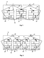
- einen Regalboden eines Regallagers mit drei Industriepaletten und der vorteilhaften Anordnung von zwei Lesegeräten;
- Fig. 2
- einen Regalboden eines Regallagers mit vier Europaletten und der nachteiligen Anordnung von zwei Lesegeräten gemäß
Fig. 1 ; - Fig. 3
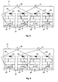
- einen Regalboden eines Regallagers mit vier Europaletten und der Anordnung von zwei verschobenen Lesegeräten;
- Fig. 4
- einen Regalboden eines Regallagers mit vier Europaletten und der Anordnung von zwei verschobenen und geschwenkten Lesegeräten;
- Fig. 5
- einen Regalboden eines Regallagers mit vier Europaletten und der Anordnung eines verschobenen Lesegerätes;
- Fig. 6
- einen Regalboden eines Regallagers mit vier Europaletten und der Anordnung eines geschwenkten Lesegerätes;
- Fig. 7
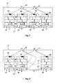
- einen Regalboden eines Regallagers gemäß
Fig. 3 mit Variation des Energieniveaus beider Lesegeräte und mit den damit verbundenen unterschiedlichen Aktivierungsreichweiten; - Fig. 8
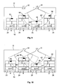
- einen Regalboden eines Regallagers gemäß
Fig. 7 in einem Ausführungsbeispiel mit unvollständiger Belegung der Stellplätze; - Fig. 9
- einen Regalboden eines Regallagers in einem Ausführungsbeispiel mit Gütern unterschiedlicher Höhe und mit Variation des Energieniveaus eines Lesegerätes; und
- Fig. 10
- einen Regalboden eines Regallagers in einem Ausführungsbeispiel mit Gütern unterschiedlicher Höhe und mit Variation des Energieniveaus beider Lesegeräte.
- Fig. 1
- a shelf of a shelf warehouse with three industrial pallets and the advantageous arrangement of two readers;
- Fig. 2
- a shelf of a rack storage with four europallets and the disadvantageous arrangement of two readers according to
Fig. 1 ; - Fig. 3
- a shelf of a racking warehouse with four europallets and the arrangement of two displaced readers;
- Fig. 4
- a shelf of a racking warehouse with four europallets and the arrangement of two displaced and tilted readers;
- Fig. 5
- a shelf of a racking warehouse with four europallets and the arrangement of a displaced reader;
- Fig. 6
- a shelf of a shelf storage with four Euro pallets and the arrangement of a pivoted reading device;
- Fig. 7
- a shelf of a shelf storage according to
Fig. 3 with variation of the energy level of both readers and with the associated different activation ranges; - Fig. 8
- a shelf of a shelf storage according to
Fig. 7 in an embodiment with incomplete occupancy of the parking spaces; - Fig. 9
- a shelf of a shelf storage in an embodiment with goods of different heights and with variation of the energy level of a reading device; and
- Fig. 10
- a shelf of a shelf storage in one embodiment with goods of different heights and with variation of the energy level of both readers.
Das erfindungsgemäße System kann beispielsweise in einem Regalsystem mit mehreren horizontalen Lagerebenen realisiert werden, in dem vorzugsweise mehrere übereinander angeordnete Regalböden vorgesehen sind, die horizontal verlaufen und auf denen Güter einzeln platziert werden können. Das System kann jedoch auch in anderen Arten von Lagern eingesetzt werden, wobei eine Lagerebene auch vertikal verlaufen könnte, wenn daran übereinander mehrere Güter angebracht werden können. Beispielsweise könnten Güter an verschiedenen definierten Positionen in eine vertikal verlaufende Schiene eingehängt werden.The system according to the invention can be realized, for example, in a shelving system with a plurality of horizontal storage levels, in which preferably a plurality of shelves arranged one above the other are provided which run horizontally and on which goods can be placed individually. However, the system can also be used in other types of warehouses be used, with a storage level could also run vertically, if it can be mounted on top of each other several goods. For example, goods could be hung at various defined positions in a vertical rail.
Die Erfindung soll jedoch anhand eines Lagersystems mit wenigstens einer horizontal verlaufenden Lagerebene erläutert werden, wobei auch der Boden einer Halle als untere Lagerebene anzusehen ist. Werden auf einem Hallenboden an definierten Positionen Güter abgestellt und diese sollen überwacht werden, eignet sich die Erfindung hierzu ebenso wie zur Überwachung von Regalen mit wenigstens einem Regalboden oberhalb eines Hallenbodens. Insbesondere bei Regalsystemen mit mehreren übereinander angeordneten Regalböden kann die Erfindung jedoch vorteilhaft dazu eingesetzt werden, um Güter auf allen definierten Stellplätzen des Regallagers zu überwachen. Die Höhe der Regalböden und damit des gesamten Regalsystems kann auch so gewählt sein, dass jeder Regalboden von einer Person manuell erreichbar ist. In diesem Fall werden nur Güter kleinerer Ausmaße in einem solchen Regallager gelagert, wobei es sich beispielsweise auch um Kartons oder Behälter mit darin befindlichen Kleingütern handeln kann.However, the invention will be explained with reference to a storage system with at least one horizontally extending storage level, wherein the floor of a hall is to be regarded as the lower storage level. If goods are parked on a hall floor at defined positions and these are to be monitored, the invention is just as suitable for monitoring shelves with at least one shelf above an indoor floor. In particular, in shelving systems with several shelves arranged one above the other, however, the invention can be advantageously used to monitor goods on all defined parking spaces of the shelf storage. The height of the shelves and thus the entire shelving system can also be chosen so that each shelf is manually accessible by one person. In this case, only goods of smaller dimensions are stored in such a rack warehouse, which may for example also be boxes or containers with small items therein.
Es kann sich jedoch auch um ein größeres Hochregallager handeln, dessen obere Regalböden üblicherweise nur mit Gabelstaplern zugängig sind. In einem solchen Hochregallager werden Güter typischerweise auf Paletten ein- und ausgelagert, und in einer zentralen Datenverarbeitungsanlage wird protokolliert, welche Palette mit welchen Gütern an welchem Stellplatz im Regallager positioniert ist. So kann zum einen der gesamte Güterbestand im Lager erfasst werden, als auch Gabelstapler bzw. deren Fahrer entsprechend angesteuert werden, um bestimmte Paletten gezielt von einem Stellplatz auslagern zu können.However, it may also be a larger high-bay warehouse, the upper shelves are usually accessible only with forklifts. In such a high-bay warehouse goods are typically stored on pallets and outsourced, and in a central data processing system is logged, which pallet is positioned with which goods at which location in the shelf storage. Thus, on the one hand, the entire goods inventory can be recorded in the warehouse, as well as forklifts or their drivers are controlled accordingly to be able to outsource specific pallets specifically from a parking space.
Um eine funkbasierte Überwachung von Gütern in einem Lager zu erreichen, wird erfindungsgemäß eine RFID-Technologie eingesetzt und jedes Gut mit einem RFID-Transponder, nachfolgend auch kurz Transponder genannt, versehen. Das Regallager wird ferner mit einer Vielzahl von Lesegeräten ausgestattet, um die Transponder der Güter im Regalsystem erfassen zu können. Im Transponder ist eine eindeutige Kennung hinterlegt, die in einer zentralen Datenverarbeitungsanlage direkt einem Gut zugeordnet sein kann. Bei Gütern, die in Behältern oder auf Paletten kommissioniert sind, ist die eindeutige Kennung dem jeweiligen Transport- bzw. Aufbewahrungsmittel zugeordnet und in der zentralen Datenverarbeitungsanlage ist hinterlegt, welche Güter wiederum diesem Transportmittel zugeordnet sind. So ist über die Überwachung des Transportmittels auch eine Überwachung der damit verbundenen Güter möglich.In order to achieve a radio-based monitoring of goods in a warehouse, an RFID technology is used according to the invention and each good is provided with an RFID transponder, also referred to below as transponder for short. The shelf warehouse is also equipped with a variety of readers to capture the transponder of the goods in the rack system. In the transponder, a unique identifier is stored, which can be assigned directly to a good in a central data processing system. For goods that are picked in containers or on pallets, the unique identifier is assigned to the respective transport or storage and stored in the central data processing system, which in turn are assigned to this means of transport. So monitoring of the means of transport and monitoring of the associated goods is possible.
Dies hat gegenüber einer visuellen Kennzeichnung beispielsweise von Paletten den Vorteil, dass der Gabelstaplerfahrer eine Palette nicht im Lager suchen muss, wenn er sie auslagern soll, sondern ihm kann mitgeteilt werden, an welchem Stellplatz in welchem Regal sich eine bestimmte Palette befindet und der Gabelstaplerfahrer kann diese Palette anfahren und aufnehmen, ohne dass er Informationen von der Palette ablesen muss. Dies erfordert natürlich, dass der Stellplatz der Palette genau bekannt ist und dem Fahrer des Gabelstaplers angezeigt werden kann.This has the advantage over a visual marking of pallets, for example, that the forklift driver does not have to search a pallet in the warehouse if he is to outsource them, but he can be told at which pitch on which shelf is a particular range and the forklift driver can approach and record this palette without having to read information from the palette. Of course, this requires that the pallet location is known exactly and can be displayed to the driver of the forklift.
In
Die Lesegeräte können jedoch auch hinter den Paletten angebracht sein, wobei die Transponder in diesem Fall ebenfalls im hinteren Bereich an den Paletten angeordnet sein sollten. Auch eine Anbringung von Lesegeräten unterhalb der Paletten ist möglich, wobei die Transponder in diesem Fall unten an den Paletten angebracht sein sollten. Insbesondere bei Gütern und/oder Verpackungen aus Materialien, die abschirmend wirken und so die verlässliche Erfassung von Transponder erschweren, hat es sich jedoch als vorteilhaft erwiesen, dass die Transponder oben an einem Gut angebracht werden. So können sie von darüber befindlichen Lesegeräten oberhalb des Gutes erfasst werden, auch wenn die Güter unterschiedliche Höhen haben bzw. Paletten unterschiedlich hoch mit Gütern beladen sind. Der jeweilige Transponder wird dann an der Oberseite der beladenen Palette angebracht, wobei er vorzugsweise von der Oberseite absteht, um negative Beeinflussungen durch den Inhalt und das Material der Palette zu vermeiden und den Transponder zuverlässig erfassen zu können.However, the readers can also be mounted behind the pallets, in which case the transponders should also be arranged at the rear on the pallets. A mounting of readers below the pallets is also possible, in which case the transponders should be attached to the bottom of the pallets. However, in particular with goods and / or packaging made of materials which have a shielding effect and thus make the reliable detection of transponders difficult, it has proven to be advantageous for the transponders to be attached to the top of a good. So they can be detected by the above located readers above the goods, even if the goods have different heights or pallets are loaded differently with goods. The respective transponder is then attached to the top of the loaded pallet, wherein it preferably protrudes from the top to negative influences by the content and To avoid the material of the pallet and to be able to detect the transponder reliably.
Der Transponder kann aber auch an der vorderen Oberkante der Palette angebracht werden, was den Vorteil hat, dass er auch von vorne zu sehen ist. Ist der Transponder beispielsweise in ein aufklebbares Label integriert, das zusätzlich bedruckt werden kann, können diese aufgedruckten Informationen von vorne abgelesen werden. Ferner kann von vorne geprüft werden, ob die Palette mit einem Transponder versehen ist. Auch bei Anbringung des Transponders an der vorderen Oberkante einer Palette steht der Transponder vorzugsweise nach oben ab, um negative Beeinflussungen durch den Inhalt und das Material der Palette zu vermeiden und den Transponder zuverlässig erfassen zu können.The transponder can also be attached to the front upper edge of the pallet, which has the advantage that it can also be seen from the front. If the transponder is integrated, for example, in a label which can be printed on, this printed information can be read from the front. Furthermore, it can be checked from the front whether the pallet is provided with a transponder. Even when attaching the transponder to the front upper edge of a pallet, the transponder is preferably upwards to avoid adverse effects of the content and the material of the pallet and to detect the transponder reliably.
In den Figuren ist ein Transponder stets vorne und unterhalb der vorderen Oberkante an einer Palette angebracht, jedoch dient dies nur der Vereinfachung der Darstellung und ist nicht als Beschränkung anzusehen. Die Anbringung des Transponders richtet sich nach dem jeweiligen Anwendungsfall und der Ausgestaltung der Palette, wobei lediglich die Ausrichtung des Transponders zum Lesegerät bzw. des Lesegerätes zum Transponder so gewählt werden sollte, dass der Abstand möglichst kurz ist bzw. keine negativen Abschirmungen auftreten.In the figures, a transponder is always attached to the front and below the front upper edge of a pallet, but this is only to simplify the illustration and is not to be considered as limiting. The attachment of the transponder depends on the particular application and the design of the pallet, wherein only the orientation of the transponder to the reader or the reader to the transponder should be chosen so that the distance is as short as possible or no negative shields occur.
Als RFID-Transponder können handelsübliche Transponder verwendet werden, die vom Fachmann entsprechend ausgestaltet sein können, wobei vorzugsweise passive Transponder ohne eigene Stromversorgung eingesetzt werden. Der Aufbau eines RFID-Transponders sieht prinzipiell eine Antenne, einen analogen Schaltkreis zum Empfangen und Senden (Transceiver), sowie einen digitalen Schaltkreis und einen permanenten Speicher vor. Die verwendeten RFID-Transponder arbeiten beispielsweise im Bereich der Langwelle bei 125-134 kHz, der Kurzwelle bei 13,56 MHz, der UHF bei 865-869 MHz bzw. 950 MHz oder der SHF bei 2,45 GHz und 5,8 GHz.Commercially available transponders can be used as RFID transponders, which can be configured accordingly by the person skilled in the art, passive transponders preferably being used without their own power supply. The structure of an RFID transponder provides in principle an antenna, an analogue circuit for receiving and transmitting (transceiver), as well as a digital circuit and a permanent memory. The RFID transponders used operate, for example, in the range of the long wave at 125-134 kHz, the shortwave at 13.56 MHz, the UHF at 865-869 MHz or 950 MHz or the SHF at 2.45 GHz and 5.8 GHz.
Vorzugsweise werden für die Erfindung passive UHF-Transponder eingesetzt, da diese besonders kostengünstig sind, einfach an einer Palette angebracht werden können und auch von vielen Firmen genutzt werden. Dadurch müssen beispielsweise keine weiteren Transponder mehr an der Palette angebracht werden, wenn Paletten bereits mit Transpondern versehen das Lager erreichen. Vielmehr besteht dann die Möglichkeit, diese Transponder weiter zu nutzen und so zusätzlich Kosten zu sparen.Preferably, passive UHF transponders are used for the invention, since they are particularly inexpensive, can be easily attached to a pallet and are also used by many companies. As a result, for example, no more transponder must be attached to the pallet when pallets already equipped with transponders reach the camp. Rather, it is then possible to continue to use these transponders and thus save additional costs.
Im Regalsystem sind mehrere Lesegeräte angebracht, die jeweils ein hochfrequentes elektromagnetisches Wechselfeld erzeugen, dem die Transponder der Güter im Bereich dieses Wechselfeldes ausgesetzt sind. Die vom Transponder über die Antenne aufgenommene Energie dient während des Kommunikationsvorganges als Stromversorgung für den Transponder. Der so aktivierte Mikrochip im Transponder decodiert die vom Lesegerät gesendeten Befehle und codiert und moduliert die Antwort in das eingestrahlte elektromagnetische Feld. Damit überträgt der Transponder wenigstens seine eigene unveränderliche Seriennummer oder auch weitere Daten des gekennzeichneten Guts an das Lesegerät, so dass das betreffende Lesegerät Transponder im Bereich seines Wechselfeldes erfassen und identifizieren kann.In the rack system several readers are attached, each generating a high-frequency alternating electromagnetic field to which the transponder of the goods are exposed in the field of this alternating field. The energy absorbed by the transponder via the antenna serves as a power supply for the transponder during the communication process. The thus activated microchip in the transponder decodes the commands sent by the reader and encodes and modulates the response in the irradiated electromagnetic field. Thus, the transponder transmits at least its own invariable serial number or other data of the marked Guts to the reader, so that the reader in question can detect and identify transponders in the field of its alternating field.
Die Reichweite des Lesegerätes hängt dabei im Wesentlichen von der Energie des Wechselfeldes ab, wobei es sich bei Betrieb eines Hochregallagers als vorteilhaft erwiesen hat, dass ein Lesegerät eine Leistung von bis zu 2 Watt (ERP) aussenden kann. Hierbei steht die Abkürzung ERP für Effective Radiated Power oder Equivalent Radiated Power, was eine standardisierte theoretische Maßeinheit für die effektive Strahlungsleistung darstellt. Die effektive Strahlungsleistung ist das Produkt der in eine Sendeantenne eingespeisten Leistung multipliziert mit deren Antennengewinn. Wird keine Richtung angegeben, gilt der Wert für die Hauptstrahlrichtung der Sendeantenne, in der gleichzeitig ihr Antennengewinn am größten ist. Vorzugsweise liegt der volle Öffnungswinkel der Antenne eines Lesegerätes nahe bei 70°, so dass in einem Winkel von 35° zur Hauptstrahlrichtung noch mindestens die Hälfte der maximalen Leistung abgestrahlt wird.The range of the reader depends essentially on the energy of the alternating field, and it has proved during operation of a high-bay warehouse advantageous that a reader can send a power of up to 2 watts (ERP). The abbreviation ERP stands for Effective Radiated Power or Equivalent Radiated Power, which represents a standardized theoretical measure of the effective radiant power. The effective radiated power is the product of the power fed into a transmitting antenna multiplied by its antenna gain. If no direction is specified, the value for the main beam direction of the transmitting antenna in which its antenna gain is the highest at the same time applies. Preferably, the full aperture angle of the antenna of a reading device is close to 70 °, so that at least half of the maximum power is radiated at an angle of 35 ° to the main beam direction.
In einem bevorzugten Ausführungsbeispiel der Erfindung verwendet das RFID-System den sogenannten 4-Kanal-Plan, bei dem nur auf 4 von 10 Hochleistungskanälen gesendet wird, wobei es sich nach den derzeitig geltenden Funk-Regularien um die Kanäle 4, 7, 10 und 13 handelt, wenn die ETSI-Norm EN 302 208 in der neusten Version (V 1.2.1) in geltendes Recht umgesetzt wurde. Dadurch kann das System von der so genannten "Listen Before Talk"-Regel (LBT) befreit werden, die in Europa dazu dient, das dem UHF-Bereich zur Verfügung stehende sehr schmale Frequenzband besser zwischen den diversen Nutzern aufzuteilen. Um eine schnelle Zuteilung der Frequenz für die neue Technologie zu ermöglichen, schreibt die LBT-Regel vor, dass ein Lesegerät vor dem Senden prüfen muss, ob ein anderer Dienst im Kanal arbeitet. Ist dies der Fall, muss es auf einen anderen Kanal ausweichen. Zudem dürfen die Lesegeräte nur vier Sekunden lang senden, bevor sie wieder das Vorhandensein anderer Nutzungen prüfen müssen. Da dies in der Praxis zu Problemen führt, hat sich der 4-Kanal-Plan für die Erfindung als vorteilhaft erwiesen, da zwar nur auf 4 Kanälen gesendet werden darf, die LBT-Regel jedoch nicht berücksichtigt werden muss. Der Betrieb anderer RFID-Systeme auf UHF-Frequenzen im Bereich des erfindungsgemäßen Systems sollte in diesem Fall jedoch vermieden werden, um die Lokalisierungsgenauigkeit und die Zuverlässigkeit der aus den RFID-Signalen gewonnenen Aussagen nicht zu beinträchtigen. Jedoch können auf den anderen Kanälen parallel zum 4-Kanal-Betrieb der RFID-Anwendungen leistungsschwache Funkanwendungen mit einer kurzen Reichweite, sogenannte Short Range Devices (SRD), betrieben werden.In a preferred embodiment of the invention, the RFID system uses the so-called 4-channel plan, in which only 4 out of 10 high-performance channels are transmitted, which according to the current radio regulations are
Die beiden in dem Ausführungsbeispiel der
Durch diese Anordnung gemäß
Der Transponder 52, der aufgrund der Reichweite des Wechselfeldes 41 nur von dem rechten Lesegerät 31 erfasst wurde, kann sich dagegen aufgrund der gleichen Logik nur rechts auf dem Stellplatz III befinden, was in der Datenverarbeitungsanlage als Position der zugehörigen Palette I-P3 mit diesem RFID-Transponder vermerkt wird. Der Transponder 51 hingegen wird im Überschneidungsbereich der beiden Wechselfelder 40 und 41 von beiden Lesegeräten 30 und 31 erfasst, was von der Logik so gewertet werden kann, dass sich die Palette I-P2 mit diesem Transponder 51 auf der mittleren Position II befinden muss, denn nur für diese Position kann eine solche Doppelerfassung eintreten.The
Durch den beschriebenen Aufbau kann somit für drei Industrieplatten verlässlich deren Position auf dem Regalboden 10 bestimmt und für die weitere Verwendung in einem Überwachungssystem hinterlegt werden. Dabei müssen nur zwei Lesegeräte eingesetzt werden, was einen Vorteil gegenüber Lösungen darstellt, bei denen beispielsweise über jedem definierten Stellplatz auf einem Regalboden ein Lesegerät angeordnet ist. Außerdem können Überschneidungen von Wechselfeldern und dadurch entstehende Doppelerfassungen vorteilhaft dazu genutzt werden, mittels einer entsprechenden Logik eine Positionsbestimmung durchzuführen. Dabei sind die beiden Lesegeräte möglichst so an den Positionen L1 und L2 oberhalb der Paletten angeordnet, dass ihre Wechselfelder die Paletten so abdecken, dass auch in den Randbereichen noch eine genaue Erfassung möglich ist.As a result of the construction described, its position on the
Sind benachbart zum Regalboden 10 weitere Regalböden links und/oder rechts davon mit einem RFID-System ausgestattet, so muss für eine genaue Positionsbestimmung der Paletten grundsätzlich gewährleistet werden, dass sich die Erfassungsbereiche der jeweils benachbarten Regalböden nicht überschneiden. Zudem dürfen keine Transponder auf Gütern erfasst werden, die im Gang vor dem Regalboden 10 transportiert werden. Vielmehr sind die Transponder ausschließlich dann zu erfassen, wenn die Güter in das Regal eingelagert oder aus dem Regal ausgelagert werden oder statisch auf dem Regalboden 10 lagern. Dies kann beispielsweise durch die Wahl geeigneter Sendeleistungen der Lesegeräte realisiert werden.If adjacent to the
Auf einem Regalboden 10 können aber nicht nur Industriepaletten, sondern beispielsweise auch Europaletten gelagert werden, die mit Abmessungen von 1200mm x 800mm weniger breit sind als Industriepaletten. Bedingt durch die anderen Abmessungen finden auf dem gleichen Regalboden 10 somit gegebenenfalls vier Europaletten Platz, wie es schematisch in
Wie in
Um die Position von Gütern auf einem Regalboden 10 mit variabler Anzahl von definierten Stellplätzen bestimmen zu können, ist daher erfindungsgemäß vorgesehen, dass die Lesegeräte 30 und 31 entlang des Regalbodens 10 verschiebbar ausgebildet sind, so dass die Positionen L1 und L2 der Lesegeräte variabel sind. Durch diese Verschiebbarkeit kann die Symmetrie der Situation in
Der gleiche Effekt kann je nach Abmessungen des Systems und der Parameter, beispielsweise der Sendeleistung, der Lesegeräte 30 und 31 eintreten, wenn die Lesegeräte 30 und 31 ergänzend oder alternativ zu einer Verschiebbarkeit auch schwenkbar ausgeführt sind. Dies ist in der
Die Verschiebung eines Lesegerätes kann beispielsweise über eine Schiene an der Halterung 11 erfolgen, entlang der das Lesegerät direkt manuell verschoben werden kann. Möglich ist auch eine Verschiebung mittels Zugseilen, die manuell entfernt von dem jeweiligen Lesegerät betätigt werden können. Dies ist insbesondere für Lesegeräte an hohen Regalböden geeignet, die nur schwer direkt zu erreichen sind. Ferner kann die Verschiebung auch automatisch erfolgen und beispielsweise durch einen Motor bewirkt werden. Zudem besteht die Möglichkeit, nur eine begrenzte Anzahl von Positionen für die Lesegeräte vorzusehen, indem in der Halterung 11 mehrere Bohrungen vorgesehen sind, in denen das Lesegerät mittels geeigneter Befestigungsmittel, wie beispielsweise Schrauben, befestigt werden kann.The displacement of a reading device can take place, for example, via a rail on the
Die Schwenkbarkeit eines Lesegerätes kann beispielsweise durch Scharniere oder Gelenke erreicht werden, über welche das Lesegerät gelagert ist. Dabei kann das Lesegerät wenigstens um eine Achse schwenkbar ausgebildet sein, wenn beispielsweise Scharniere eingesetzt werden. Es kann aber auch beliebig um mehrere Achsen schwenkbar sein, wenn beispielsweise Kugelgelenke eingesetzt werden. Auch das Schwenken eines Lesegerätes kann manuell oder motorgetrieben erfolgen. Weiterhin ist es möglich, anstelle von Scharnieren oder Gelenken eine separate Halterung für die Lesegeräte vorzusehen, die den Schwenkwinkel für das Lesegerät fest vorgibt und die durch eine Halterung mit einem anderen fest vorgegebenen Schwenkwinkel ersetzt werden kann. Zum Einstellen eines anderen Schwenkwinkels muss hierbei das Lesegerät mit der Halterung demontiert werden, die Halterung muss durch eine andere Halterung ausgetauscht werden und anschließend muss das Lesegerät mit der neuen Halterung wieder montiert werden.The pivotability of a reading device can be achieved, for example, by hinges or joints, over which the reading device is mounted. In this case, the reading device can be designed to be pivotable about at least one axis, for example when hinges are used. But it can also be arbitrarily pivotable about several axes, for example when ball joints are used. Also, the pivoting of a reading device can be done manually or motorized. Furthermore, it is possible to provide a separate holder for the readers instead of hinges or hinges, which sets the pivot angle for the reader fixed and can be replaced by a holder with another fixed predetermined pivoting angle. In order to set a different swivel angle, the reader must be disassembled with the holder, the holder must be replaced by another holder and then the reader must be re-mounted with the new holder.
Allgemein zu beachten ist, dass die Lesegeräte so an der Halterung 11 befestigt sein müssen, dass eine Palette, die die Halterung 11 nur partiell belastet, nicht zu einer Verkippung oder zu einer transversalen Verschiebung der Lesegeräte führt. Um ein Lesegerät bis zu einer vorgegebenen Position zu verschieben bzw. in eine vorgegebene Lage zu schwenken, können Anschläge oder sonstige Mittel vorgesehen sein, um das Lesegerät entsprechend auszurichten.It should be noted in general that the readers must be attached to the
In den Zuständen der
Zusätzlich zu der Verschiebbarkeit und/oder Schwenkbarkeit der Lesegeräte 30 und 31 ist daher erfindungsgemäß vorgesehen, dass das Energieniveau des elektromagnetischen Wechselfeldes wenigstens eines Lesegerätes innerhalb eines von zwei Randwerten begrenzten Bereiches variiert werden kann. Durch diese Variation des Energieniveaus des Wechselfeldes eines Lesegerätes ändert sich die Reichweite, innerhalb der Transponder von einem Lesegerät erfasst werden können. Durchläuft ein von einem Lesegerät erzeugtes Wechselfeld beispielsweise mehrere Zwischenwerte zwischen einem maximalen und einem minimalen Energieniveau, tritt der Fall ein, dass ein Transponder bei einem höheren Energieniveau noch gelesen werden kann, während er ab einem bestimmten niedrigeren Energieniveau nicht mehr erfasst wird. Auch diese Informationen werden von der Logik der Datenverarbeitungseinheit verarbeitet und können dazu genutzt werden, um zu ermitteln, ob sich die in der Mitte erfassten Transponder 54 und 55 an einer Palette auf der Position B oder an einer Palette auf der Position C befinden.In addition to the displaceability and / or pivotability of the
Dieser Vorgang soll beispielhaft anhand der
Wie aus
Das Gleiche gilt für eine Situation, in der nicht alle Stellplätze auf dem Regalboden 10 mit Paletten belegt sind, wie es beispielsweise in der
Es kann dabei ausreichend sein, die Variation des Energieniveaus eines Wechselfeldes nur an einem der Lesegeräte vorzusehen, da dies für viele Anwendungsfälle ausreicht, um eine genaue Positionsbestimmung durchführen zu können. Insbesondere für Paletten mit unterschiedlichen Höhen ist jedoch oftmals nur basierend auf der Ermittelung des ungefähren Abstands zwischen einem Lesegerät und einem Transponder keine eindeutige Aussage darüber zu treffen, ob sich der Transponder an einer Palette unterhalb des betreffenden Lesegerätes befindet oder doch an einer Palette an einer benachbarten Position. Eine solche Situation ist beispielsweise in der
Aus
Ob für eine Positionsbestimmung das Wechselfeld nur eines Lesegerätes oder beider Lesegeräte variiert wird, kann standardmäßig festgelegt sein oder bei Bedarf selektiv angesteuert werden. Eine selektive Ansteuerung kann beispielsweise erfolgen, wenn eine Situation wie in
Ferner kann vorgesehen sein, dass die Variation des Energieniveaus eines oder mehrerer Lesegeräte nicht fortlaufend durchgeführt wird, sondern nur, wenn eine neue Palette auf dem Regalboden detektiert wurde. Falls beispielsweise zu einem ersten Messzeitpunkt die Positionen aller Paletten auf dem Regalboden eindeutig bestimmt werden konnten und beim nächsten Messzeitpunkt keine neuen Transponder detektiert werden und auch keine Paletten mit Transpondern entfernt wurden, muss keine Variation des Energieniveaus der Lesegeräte erfolgen, falls davon ausgegangen werden kann, dass sich die Positionen der Paletten untereinander nicht verändert haben können. Wird dann zu einem weiteren Messzeitpunkt festgestellt, dass ein neuer Transponder hinzugekommen ist, kann die Variation des Energieniveaus für ein oder zwei Lesegeräte durchgeführt werden, um die Position des neuen Transponders einmalig genau zu bestimmen.Furthermore, it can be provided that the variation of the energy level of one or more readers is not carried out continuously, but only if a new pallet has been detected on the shelf. If, for example, the positions of all pallets on the shelf could be uniquely determined at a first measuring time and no new transponders were detected at the next measuring time and no pallets with transponders were removed, no variation of the energy level of the readers is required, if it can be assumed that the positions of the pallets with each other can not have changed. If it is then determined at a further measurement time that a new transponder has been added, the variation of the energy level for one or two readers can be carried out in order to determine the position of the new transponder once.
Auch wenn eine Palette den Regalboden 10 verlässt, muss nicht unbedingt eine Variation des Energieniveaus für die verbleibenden Paletten durchgeführt werden. Wird beispielsweise zu einem weiteren Messzeitpunkt festgestellt, dass einer der beiden äußeren Transponder 53 oder 56 nicht mehr detektiert werden kann, da zugehörige Paletten entnommen wurden, muss keine Variation des Energieniveaus durchgeführt werden, da sich an der Position der beiden mittleren Paletten offensichtlich nichts geändert hat.Even if a pallet leaves the
Auch wenn nur eine der beiden mittleren Paletten 24 oder 25 entfernt und durch eine andere Palette ersetzt wird, was durch das Erfassen eines bisher unbekannten Transponders auf einer der mittleren Positionen festgestellt werden kann, während ein bisher auf der Position B oder C erfasster Transponder nicht mehr erfasst werden kann, muss dies nicht zwingend eine Variation des Energieniveaus erfordern. Für den verbleibenden Transponder kann davon ausgegangen werden, dass sich die zugehörige Palette noch an der selben Stelle auf dem Regalboden 10 befindet, so dass sich der neu erfasste Transponder zwangsläufig auf der anderen mittleren Position befinden muss. Nur wenn beide mittleren Paletten annähernd gleichzeitig entfernt und durch neue Paletten ersetzt werden, ist erneut unklar, wie die Positionen in der Mitte des Regalbodens 10 belegt sind, so dass nun eine Variation des Energieniveaus durchgeführt werden sollte. Das wäre auch erforderlich, wenn eine mittlere Palette entfernt wurde, die andere mittlere Palette auf diese Position verschoben wurde und auf der so frei gewordenen mittleren Position eine neue Palette abgestellt wurde.Even if only one of the two
Die beschriebene Vorgehensweise zur Vermeidung der Variation des Energieniveaus von Lesegeräten kann jedoch nur gewählt werden, wenn die Vorgänge im Lager so sind, dass immer noch mit ausreichender Genauigkeit auf die Position einer Palette im Regalsystem geschlossen werden kann. Die in der Datenverarbeitungsanlage hinterlegte Logik wertet somit vorzugsweise nicht immer wieder alle Signale aus, um immer wieder neu eine vollständige Positionsbestimmung auf einem Regalboden 10 durchzuführen, sondern einmal ermittelte Positionen werden von der intelligenten Datenverarbeitungsanlage dazu verwendet, um logisch zu ermitteln, welche Änderungen auf dem Regalboden 10 eingetreten sein können, wenn Transponder sich entfernen oder neu hinzukommen. Die Variation eines Energieniveaus wird somit vorzugsweise nur bei Bedarf durchgeführt, oder wird angewendet, um zwischenzeitlich aktuell hinterlegte Positionen zu bestätigen und die Wahrscheinlichkeit ihrer Richtigkeit zu erhöhen. Da die Variation des Energieniveaus mehrerer Lesegeräte innerhalb eines größeren Lagers und die entsprechende Auswertung der Signale sehr lange dauern kann, hat diese Vorgehensweise den Vorteil, dass beispielsweise eine Inventurmessung über alle Lesegeräte so schnell wie möglich durchgeführt werden kann. Bekannte Positionen von Paletten müssen dabei nicht nochmals durch eine Variation des Energieniveaus von Lesegeräten bestätigt werden, sondern für diese Paletten muss nur bestätigt werden, dass sie sich noch auf dem Regalboden befinden. Lediglich für neu hinzugekommene Transponder muss gegebenenfalls eine Variation des Energieniveaus einzelner oder aller Lesegeräte eines Regalbodens 10 oder Lagers durchgeführt werden, wenn sich dies durch keine andere Logik verhindern lässt bzw. die Wahrscheinlichkeit der richtigen Lokalisierung erhöht werden soll.However, the described procedure for avoiding the variation of the energy level of readers can only be selected if the processes in the warehouse are such that the position of a pallet in the rack system can still be closed with sufficient accuracy. The logic stored in the data processing system thus preferably does not evaluate all the signals again and again in order to carry out a complete position determination on a
Wenn auf dem Regalboden 10 nach vier Europaletten wieder drei Industriepaletten gelagert werden sollen, können die Lesegeräte 30 und 31 für eine Erfassung der einzelnen Paletten einfach wieder in die Positionen L1 und L2 gemäß
- 1010
- Lagerebene, RegalbodenStorage level, shelf
- 1111
- Halterung, SchieneBracket, rail
- 20, 21, 2220, 21, 22
- Industriepaletteindustrial pallet
- 23, 24, 25, 2623, 24, 25, 26
- Europaletteeuro pallet
- 30, 3130, 31
- Lesegerätreader
- 40,4140.41
- Wechselfeldalternating field
- 40', 41'40 ', 41'
- Wechselfeld mit minimalem EnergieniveauAlternating field with minimal energy level
- 40", 41"40 ", 41"
- Wechselfeld mit maximalem EnergieniveauAlternating field with maximum energy level
- 50, 51, 52, 53, 54, 55, 5650, 51, 52, 53, 54, 55, 56
- RFID-Transponder, TransponderRFID transponder, transponder
- I-P1, I-P2, I-P3I-P1, I-P2, I-P3
- Industriepaletteindustrial pallet
- I, II, IIII, II, III
- Position/Stellplatz IndustriepalettePosition / Pitch industrial pallet
- E-P1, E-P2, E-P3, E-P4E-P1, E-P2, E-P3, E-P4
- Europaletteeuro pallet
- A, B, C, DA, B, C, D
- Position/Stellplatz EuropalettePosition / Pitch europallet
- L1, L2L1, L2
- Position LesegerätPosition reader
Claims (12)
- A system for storing and monitoring goods, comprising at least one storage level (10) on which the goods can be placed, whereby each item is provided with at least one passive RFID transponder, and the system comprises several reading devices (30, 31) for detecting these RFID transponders, whereby each storage level (10) is associated with at least two reading devices (30, 31), and the reading devices (30, 31) are in communication with a data processing unit that has means for evaluating detected RFID signals of the RFID transponders, and characterized in that
the goods can be placed in defined positions so that each item is associated with a defined position, and the defined positions for goods are arranged next to each other in a row on a given storage level (10), and the reading devices (30, 31) are arranged along this row of defined positions, and, for purposes of a multiple detection of RFID transponders, they can be moved towards each other along this row and/or they are configured so as to pivot relative thereto, and in that at least one reading device (30, 31) is configured in such a way that the energy level of the emitted alternating current field of this reading device (30, 31) is variable. - The system according to claim 1,
characterized in that
the at least one reading device (30, 31) can be moved from a first location into a second location by being pushed and/or pivoted, whereby, in the first location, when all of the positions of the associated storage level (10) are occupied with goods, no RFID transponder can be detected simultaneously by two adjacent reading devices (30, 31), whereas in the second location, when all of the positions of this storage level (10) are occupied with goods, at least one RFID transponder can be detected simultaneously by two adjacent reading devices (30, 31). - The system according to one or both of claims 1 and 2,
characterized in that
the energy level of the emitted alternating current field of the at least one reading device (30, 31) is variable within a range limited by two boundary values in that, when all of the positions of the associated storage level (10) are occupied with goods, at least one RFID transponder can be detected by a reading device (30, 31) at a given value of the energy level, whereas the same RFID transponder cannot be detected by this reading device (30, 31) at a lower value of the energy level. - The system according to one of claims 1 to 3,
characterized in that
one storage level (10) runs horizontally and in that at least two reading devices (30, 31) are arranged above the storage level (10) and the goods, whereby the RFID transponders are each installed in the upper section of the goods. - The system according to claim 4,
characterized in that
the at least one reading device (30, 31) is arranged on a holder (11) that runs parallel to the storage level (10), whereby the holder (11) comprises a rail in which the at least one reading device (30, 31) is installed in such a way that it can move. - System according to one of claims 1 to 5,
characterized in that
the energy level of the alternating field of the at least one reading device (30, 31) can be varied between approximately 2 watts ERP and approximately 50 milliwatts ERP. - A method for monitoring goods with a system according to one of claims 1 to 6, in which signals of the reading device (30, 31) are transmitted to a data processing unit for evaluation, whereby the evaluation comprises an association of RFID transponders, and the goods associated with them, to a position on a storage level (10),
characterized in that
at least one reading device (30, 31) is moved from a first location into a second location by being pushed and/or pivoted for purposes of a simultaneous detection of at least one RFID transponder by two adj acent reading devices when all of the positions of this storage level (10) are occupied, whereby in the first location, when all of the positions of the associated storage level (10) are occupied with goods, no RFID transponder can be detected simultaneously by two adjacent reading devices (30, 31), and a position determination is carried out by differentiating between RFID transponders that have been detected one time and those that have been detected two times, and in that, in the second location, the energy level of the emitted alternating current field of at least one reading device (30, 31) varies between two boundary values, whereby at least one RFID transponder is detected by one reading device (30, 31) at a given value of the energy level, whereas the same RFID transponder is not detected by this reading device (30, 31) at a lower value of the energy level. - The method according to claim 7,
characterized in that,
when the data processing unit evaluates RFID signals of the reading devices (30, 31), it differentiates between RFID transponders that can be detected by only one reading device (30, 31) and RFID transponders that can be detected simultaneously by two reading devices (30, 31), and in that an RFID transponder that is detected by only one reading device (30, 31) is associated with a position on the storage level (10) in the range of this reading device (30, 31) that falls outside of the detection zone of the other reading devices (30, 31) of that particular storage level (10), whereas an RFID transponder that is detected simultaneously by two adjacent reading devices (30, 31) is associated with a position that falls in the intersection area of the detection zones of these two adjacent reading devices (30, 31). - The method according to claim 8,
characterized in that
an RFID transponder that is detected by two adjacent reading devices (30, 31) - after the energy level of at least one of these two reading devices (30, 31) has been varied - is associated with the position in the intersection area of the detection zones of these two adjacent reading devices (30, 31) that is closer to the reading device (30, 31) with which that particular RFID transponder is detected at a higher as well as at a lower energy level. - The method according to one of claims 7 to 9,
characterized in that
the variation of the energy level of at least one reading device (30, 31) is initiated in that an RFID transponder on the storage level (10) that had not yet been detected is detected by at least one reading device (30, 31). - The method according to claim 10,
characterized in that
the variation of the energy level of at least one reading device (30, 31) is initiated in that an RFID transponder on the storage level (10) that had not yet been detected is detected simultaneously by two adjacent reading devices (30, 31). - The method according to claim 11,
characterized in that,
when the energy level of at least one reading device (30, 31) is varied, the energy level of the alternating current field of this reading device (30, 31) is reduced incrementally from approximately 2 watts ERP to approximately 50 milliwatts ERP.
Applications Claiming Priority (1)
| Application Number | Priority Date | Filing Date | Title |
|---|---|---|---|
| DE102011003029A DE102011003029A1 (en) | 2011-01-24 | 2011-01-24 | System and method for storage and monitoring of goods using RFID technology |
Publications (3)
| Publication Number | Publication Date |
|---|---|
| EP2479720A2 EP2479720A2 (en) | 2012-07-25 |
| EP2479720A3 EP2479720A3 (en) | 2013-01-23 |
| EP2479720B1 true EP2479720B1 (en) | 2014-03-19 |
Family
ID=45531181
Family Applications (1)
| Application Number | Title | Priority Date | Filing Date |
|---|---|---|---|
| EP12150220.7A Not-in-force EP2479720B1 (en) | 2011-01-24 | 2012-01-05 | System and method for storing and monitoring goods using RFID technology |
Country Status (2)
| Country | Link |
|---|---|
| EP (1) | EP2479720B1 (en) |
| DE (1) | DE102011003029A1 (en) |
Families Citing this family (1)
| Publication number | Priority date | Publication date | Assignee | Title |
|---|---|---|---|---|
| CN104444384B (en) * | 2014-10-27 | 2017-11-21 | 北京京东尚科信息技术有限公司 | The method and apparatus for handling code-disc data |
Family Cites Families (4)
| Publication number | Priority date | Publication date | Assignee | Title |
|---|---|---|---|---|
| US7132945B2 (en) * | 2003-08-20 | 2006-11-07 | Dematic Corp. | Material support system for supporting items having radio frequency identification (RFID) tags |
| EP3699806A1 (en) | 2006-07-11 | 2020-08-26 | Mojix, Inc. | Rfid system |
| DE102006052708B3 (en) * | 2006-11-08 | 2008-06-19 | Siemens Ag | Arrangement and method for data acquisition |
| DE202007009056U1 (en) | 2007-06-27 | 2007-10-25 | Robert Bosch Gmbh | Material warehouse with RFID antenna |
-
2011
- 2011-01-24 DE DE102011003029A patent/DE102011003029A1/en not_active Withdrawn
-
2012
- 2012-01-05 EP EP12150220.7A patent/EP2479720B1/en not_active Not-in-force
Also Published As
| Publication number | Publication date |
|---|---|
| EP2479720A2 (en) | 2012-07-25 |
| EP2479720A3 (en) | 2013-01-23 |
| DE102011003029A1 (en) | 2012-07-26 |
Similar Documents
| Publication | Publication Date | Title |
|---|---|---|
| EP2903086B1 (en) | RFID reading device for shelf occupancy detection | |
| EP2937279B1 (en) | Freight loading system for loading and unloading of an item of freight, method for creating and/or updating a loading plan | |
| EP1710203B1 (en) | Floor conveyor comprising a device for picking up loads | |
| EP2675709B1 (en) | Cargo loading system and method for controlling a multiple roller conveyor | |
| EP3291144B1 (en) | Rfid device and method for detecting compartment occupation | |
| EP1767471B1 (en) | System for identification and administration of pallets | |
| EP2479719A2 (en) | System and method for storing and monitoring goods using RFID technology | |
| DE102011009739A1 (en) | Device and method for detecting the inventory of a sales and / or storage facility as well as a warehouse management system equipped therewith | |
| EP3087877B1 (en) | Checkout system assembly with goods separator detection | |
| EP2087455B1 (en) | Arrangement and method for data acquisition | |
| EP2500850B1 (en) | Method and system for monitoring objects | |
| EP1710204B1 (en) | Industrial truck with a device for communicating with an identification system mounted on a vertically movable forks carrier | |
| EP2987760B1 (en) | Industrial truck | |
| EP3279686B1 (en) | Radio frequency identification device for communicating with rfid transponders and method for allocating rfid transponders | |
| EP2479720B1 (en) | System and method for storing and monitoring goods using RFID technology | |
| EP3452966B1 (en) | Storage logistics method | |
| EP0895212A2 (en) | A roller carriage having a transponder | |
| DE102014212108A1 (en) | TRANSPORT CONTAINER WITH INTERNAL VOLUME MONITORING AND LOGISTICS SYSTEM | |
| EP2456658B1 (en) | Container system and logistics system for ships | |
| EP1024096B1 (en) | Logistical system for shipping and receiving goods,devices,for reading data from one or more data storing devices and/or writing data in one or more data storing devices,used in such a logistical system | |
| EP2774875A1 (en) | System for completing a warehouse for small articles | |
| EP3276552A1 (en) | Rfid communication system for electronic stock monitoring of a flow rack | |
| EP3273382A1 (en) | Rfid reading device and method for compartment occupancy detection in a shelf | |
| EP3577428B1 (en) | Storage system comprising a detection arrangement assigned to the storage area | |
| DE10202477B4 (en) | Reusable containers for handling goods and methods for locating the same in a reusable container circulating system |
Legal Events
| Date | Code | Title | Description |
|---|---|---|---|
| PUAI | Public reference made under article 153(3) epc to a published international application that has entered the european phase |
Free format text: ORIGINAL CODE: 0009012 |
|
| AK | Designated contracting states |
Kind code of ref document: A2 Designated state(s): AL AT BE BG CH CY CZ DE DK EE ES FI FR GB GR HR HU IE IS IT LI LT LU LV MC MK MT NL NO PL PT RO RS SE SI SK SM TR |
|
| AX | Request for extension of the european patent |
Extension state: BA ME |
|
| REG | Reference to a national code |
Ref country code: DE Ref legal event code: R079 Ref document number: 502012000445 Country of ref document: DE Free format text: PREVIOUS MAIN CLASS: G06Q0010080000 Ipc: G06K0007100000 |
|
| PUAL | Search report despatched |
Free format text: ORIGINAL CODE: 0009013 |
|
| AK | Designated contracting states |
Kind code of ref document: A3 Designated state(s): AL AT BE BG CH CY CZ DE DK EE ES FI FR GB GR HR HU IE IS IT LI LT LU LV MC MK MT NL NO PL PT RO RS SE SI SK SM TR |
|
| AX | Request for extension of the european patent |
Extension state: BA ME |
|
| RIC1 | Information provided on ipc code assigned before grant |
Ipc: G06K 7/10 20060101AFI20121218BHEP Ipc: B65G 1/137 20060101ALI20121218BHEP Ipc: G06Q 10/08 20120101ALI20121218BHEP |
|
| REG | Reference to a national code |
Ref country code: HK Ref legal event code: DE Ref document number: 1170326 Country of ref document: HK |
|
| 17P | Request for examination filed |
Effective date: 20130723 |
|
| RBV | Designated contracting states (corrected) |
Designated state(s): AL AT BE BG CH CY CZ DE DK EE ES FI FR GB GR HR HU IE IS IT LI LT LU LV MC MK MT NL NO PL PT RO RS SE SI SK SM TR |
|
| GRAP | Despatch of communication of intention to grant a patent |
Free format text: ORIGINAL CODE: EPIDOSNIGR1 |
|
| INTG | Intention to grant announced |
Effective date: 20130920 |
|
| GRAS | Grant fee paid |
Free format text: ORIGINAL CODE: EPIDOSNIGR3 |
|
| GRAA | (expected) grant |
Free format text: ORIGINAL CODE: 0009210 |
|
| AK | Designated contracting states |
Kind code of ref document: B1 Designated state(s): AL AT BE BG CH CY CZ DE DK EE ES FI FR GB GR HR HU IE IS IT LI LT LU LV MC MK MT NL NO PL PT RO RS SE SI SK SM TR |
|
| REG | Reference to a national code |
Ref country code: GB Ref legal event code: FG4D Free format text: NOT ENGLISH |
|
| REG | Reference to a national code |
Ref country code: CH Ref legal event code: EP |
|
| REG | Reference to a national code |
Ref country code: IE Ref legal event code: FG4D Free format text: LANGUAGE OF EP DOCUMENT: GERMAN |
|
| REG | Reference to a national code |
Ref country code: AT Ref legal event code: REF Ref document number: 658079 Country of ref document: AT Kind code of ref document: T Effective date: 20140415 |
|
| REG | Reference to a national code |
Ref country code: DE Ref legal event code: R096 Ref document number: 502012000445 Country of ref document: DE Effective date: 20140430 |
|
| REG | Reference to a national code |
Ref country code: NL Ref legal event code: T3 |
|
| PG25 | Lapsed in a contracting state [announced via postgrant information from national office to epo] |
Ref country code: NO Free format text: LAPSE BECAUSE OF FAILURE TO SUBMIT A TRANSLATION OF THE DESCRIPTION OR TO PAY THE FEE WITHIN THE PRESCRIBED TIME-LIMIT Effective date: 20140619 Ref country code: LT Free format text: LAPSE BECAUSE OF FAILURE TO SUBMIT A TRANSLATION OF THE DESCRIPTION OR TO PAY THE FEE WITHIN THE PRESCRIBED TIME-LIMIT Effective date: 20140319 |
|
| REG | Reference to a national code |
Ref country code: LT Ref legal event code: MG4D |
|
| PG25 | Lapsed in a contracting state [announced via postgrant information from national office to epo] |
Ref country code: CY Free format text: LAPSE BECAUSE OF FAILURE TO SUBMIT A TRANSLATION OF THE DESCRIPTION OR TO PAY THE FEE WITHIN THE PRESCRIBED TIME-LIMIT Effective date: 20140319 Ref country code: SE Free format text: LAPSE BECAUSE OF FAILURE TO SUBMIT A TRANSLATION OF THE DESCRIPTION OR TO PAY THE FEE WITHIN THE PRESCRIBED TIME-LIMIT Effective date: 20140319 Ref country code: FI Free format text: LAPSE BECAUSE OF FAILURE TO SUBMIT A TRANSLATION OF THE DESCRIPTION OR TO PAY THE FEE WITHIN THE PRESCRIBED TIME-LIMIT Effective date: 20140319 |
|
| PG25 | Lapsed in a contracting state [announced via postgrant information from national office to epo] |
Ref country code: LV Free format text: LAPSE BECAUSE OF FAILURE TO SUBMIT A TRANSLATION OF THE DESCRIPTION OR TO PAY THE FEE WITHIN THE PRESCRIBED TIME-LIMIT Effective date: 20140319 Ref country code: HR Free format text: LAPSE BECAUSE OF FAILURE TO SUBMIT A TRANSLATION OF THE DESCRIPTION OR TO PAY THE FEE WITHIN THE PRESCRIBED TIME-LIMIT Effective date: 20140319 Ref country code: RS Free format text: LAPSE BECAUSE OF FAILURE TO SUBMIT A TRANSLATION OF THE DESCRIPTION OR TO PAY THE FEE WITHIN THE PRESCRIBED TIME-LIMIT Effective date: 20140319 |
|
| PG25 | Lapsed in a contracting state [announced via postgrant information from national office to epo] |
Ref country code: EE Free format text: LAPSE BECAUSE OF FAILURE TO SUBMIT A TRANSLATION OF THE DESCRIPTION OR TO PAY THE FEE WITHIN THE PRESCRIBED TIME-LIMIT Effective date: 20140319 Ref country code: RO Free format text: LAPSE BECAUSE OF FAILURE TO SUBMIT A TRANSLATION OF THE DESCRIPTION OR TO PAY THE FEE WITHIN THE PRESCRIBED TIME-LIMIT Effective date: 20140319 Ref country code: BG Free format text: LAPSE BECAUSE OF FAILURE TO SUBMIT A TRANSLATION OF THE DESCRIPTION OR TO PAY THE FEE WITHIN THE PRESCRIBED TIME-LIMIT Effective date: 20140619 Ref country code: CZ Free format text: LAPSE BECAUSE OF FAILURE TO SUBMIT A TRANSLATION OF THE DESCRIPTION OR TO PAY THE FEE WITHIN THE PRESCRIBED TIME-LIMIT Effective date: 20140319 Ref country code: IS Free format text: LAPSE BECAUSE OF FAILURE TO SUBMIT A TRANSLATION OF THE DESCRIPTION OR TO PAY THE FEE WITHIN THE PRESCRIBED TIME-LIMIT Effective date: 20140719 |
|
| PG25 | Lapsed in a contracting state [announced via postgrant information from national office to epo] |
Ref country code: PL Free format text: LAPSE BECAUSE OF FAILURE TO SUBMIT A TRANSLATION OF THE DESCRIPTION OR TO PAY THE FEE WITHIN THE PRESCRIBED TIME-LIMIT Effective date: 20140319 Ref country code: SK Free format text: LAPSE BECAUSE OF FAILURE TO SUBMIT A TRANSLATION OF THE DESCRIPTION OR TO PAY THE FEE WITHIN THE PRESCRIBED TIME-LIMIT Effective date: 20140319 Ref country code: ES Free format text: LAPSE BECAUSE OF FAILURE TO SUBMIT A TRANSLATION OF THE DESCRIPTION OR TO PAY THE FEE WITHIN THE PRESCRIBED TIME-LIMIT Effective date: 20140319 |
|
| REG | Reference to a national code |
Ref country code: DE Ref legal event code: R097 Ref document number: 502012000445 Country of ref document: DE |
|
| PG25 | Lapsed in a contracting state [announced via postgrant information from national office to epo] |
Ref country code: PT Free format text: LAPSE BECAUSE OF FAILURE TO SUBMIT A TRANSLATION OF THE DESCRIPTION OR TO PAY THE FEE WITHIN THE PRESCRIBED TIME-LIMIT Effective date: 20140721 |
|
| PLBE | No opposition filed within time limit |
Free format text: ORIGINAL CODE: 0009261 |
|
| STAA | Information on the status of an ep patent application or granted ep patent |
Free format text: STATUS: NO OPPOSITION FILED WITHIN TIME LIMIT |
|
| PG25 | Lapsed in a contracting state [announced via postgrant information from national office to epo] |
Ref country code: DK Free format text: LAPSE BECAUSE OF FAILURE TO SUBMIT A TRANSLATION OF THE DESCRIPTION OR TO PAY THE FEE WITHIN THE PRESCRIBED TIME-LIMIT Effective date: 20140319 |
|
| 26N | No opposition filed |
Effective date: 20141222 |
|
| REG | Reference to a national code |
Ref country code: DE Ref legal event code: R097 Ref document number: 502012000445 Country of ref document: DE Effective date: 20141222 |
|
| PGFP | Annual fee paid to national office [announced via postgrant information from national office to epo] |
Ref country code: IT Payment date: 20150131 Year of fee payment: 4 |
|
| PG25 | Lapsed in a contracting state [announced via postgrant information from national office to epo] |
Ref country code: BE Free format text: LAPSE BECAUSE OF NON-PAYMENT OF DUE FEES Effective date: 20150131 |
|
| PG25 | Lapsed in a contracting state [announced via postgrant information from national office to epo] |
Ref country code: SI Free format text: LAPSE BECAUSE OF FAILURE TO SUBMIT A TRANSLATION OF THE DESCRIPTION OR TO PAY THE FEE WITHIN THE PRESCRIBED TIME-LIMIT Effective date: 20140319 |
|
| REG | Reference to a national code |
Ref country code: DE Ref legal event code: R119 Ref document number: 502012000445 Country of ref document: DE |
|
| REG | Reference to a national code |
Ref country code: NL Ref legal event code: V1 Effective date: 20150801 |
|
| REG | Reference to a national code |
Ref country code: CH Ref legal event code: PL |
|
| PG25 | Lapsed in a contracting state [announced via postgrant information from national office to epo] |
Ref country code: LU Free format text: LAPSE BECAUSE OF FAILURE TO SUBMIT A TRANSLATION OF THE DESCRIPTION OR TO PAY THE FEE WITHIN THE PRESCRIBED TIME-LIMIT Effective date: 20150105 |
|
| PG25 | Lapsed in a contracting state [announced via postgrant information from national office to epo] |
Ref country code: MC Free format text: LAPSE BECAUSE OF FAILURE TO SUBMIT A TRANSLATION OF THE DESCRIPTION OR TO PAY THE FEE WITHIN THE PRESCRIBED TIME-LIMIT Effective date: 20140319 Ref country code: NL Free format text: LAPSE BECAUSE OF NON-PAYMENT OF DUE FEES Effective date: 20150801 |
|
| PG25 | Lapsed in a contracting state [announced via postgrant information from national office to epo] |
Ref country code: CH Free format text: LAPSE BECAUSE OF NON-PAYMENT OF DUE FEES Effective date: 20150131 Ref country code: LI Free format text: LAPSE BECAUSE OF NON-PAYMENT OF DUE FEES Effective date: 20150131 Ref country code: DE Free format text: LAPSE BECAUSE OF NON-PAYMENT OF DUE FEES Effective date: 20150801 |
|
| REG | Reference to a national code |
Ref country code: FR Ref legal event code: ST Effective date: 20150930 |
|
| REG | Reference to a national code |
Ref country code: IE Ref legal event code: MM4A |
|
| PG25 | Lapsed in a contracting state [announced via postgrant information from national office to epo] |
Ref country code: FR Free format text: LAPSE BECAUSE OF NON-PAYMENT OF DUE FEES Effective date: 20150202 |
|
| PG25 | Lapsed in a contracting state [announced via postgrant information from national office to epo] |
Ref country code: IE Free format text: LAPSE BECAUSE OF NON-PAYMENT OF DUE FEES Effective date: 20150105 |
|
| PG25 | Lapsed in a contracting state [announced via postgrant information from national office to epo] |
Ref country code: GR Free format text: LAPSE BECAUSE OF FAILURE TO SUBMIT A TRANSLATION OF THE DESCRIPTION OR TO PAY THE FEE WITHIN THE PRESCRIBED TIME-LIMIT Effective date: 20140620 |
|
| GBPC | Gb: european patent ceased through non-payment of renewal fee |
Effective date: 20160105 |
|
| PG25 | Lapsed in a contracting state [announced via postgrant information from national office to epo] |
Ref country code: GB Free format text: LAPSE BECAUSE OF NON-PAYMENT OF DUE FEES Effective date: 20160105 |
|
| PG25 | Lapsed in a contracting state [announced via postgrant information from national office to epo] |
Ref country code: IT Free format text: LAPSE BECAUSE OF NON-PAYMENT OF DUE FEES Effective date: 20160105 Ref country code: MT Free format text: LAPSE BECAUSE OF FAILURE TO SUBMIT A TRANSLATION OF THE DESCRIPTION OR TO PAY THE FEE WITHIN THE PRESCRIBED TIME-LIMIT Effective date: 20140319 |
|
| PG25 | Lapsed in a contracting state [announced via postgrant information from national office to epo] |
Ref country code: SM Free format text: LAPSE BECAUSE OF FAILURE TO SUBMIT A TRANSLATION OF THE DESCRIPTION OR TO PAY THE FEE WITHIN THE PRESCRIBED TIME-LIMIT Effective date: 20140319 Ref country code: HU Free format text: LAPSE BECAUSE OF FAILURE TO SUBMIT A TRANSLATION OF THE DESCRIPTION OR TO PAY THE FEE WITHIN THE PRESCRIBED TIME-LIMIT; INVALID AB INITIO Effective date: 20120105 |
|
| PG25 | Lapsed in a contracting state [announced via postgrant information from national office to epo] |
Ref country code: TR Free format text: LAPSE BECAUSE OF FAILURE TO SUBMIT A TRANSLATION OF THE DESCRIPTION OR TO PAY THE FEE WITHIN THE PRESCRIBED TIME-LIMIT Effective date: 20140319 |
|
| REG | Reference to a national code |
Ref country code: AT Ref legal event code: MM01 Ref document number: 658079 Country of ref document: AT Kind code of ref document: T Effective date: 20170105 |
|
| PG25 | Lapsed in a contracting state [announced via postgrant information from national office to epo] |
Ref country code: AT Free format text: LAPSE BECAUSE OF NON-PAYMENT OF DUE FEES Effective date: 20170105 |
|
| PG25 | Lapsed in a contracting state [announced via postgrant information from national office to epo] |
Ref country code: MK Free format text: LAPSE BECAUSE OF FAILURE TO SUBMIT A TRANSLATION OF THE DESCRIPTION OR TO PAY THE FEE WITHIN THE PRESCRIBED TIME-LIMIT Effective date: 20140319 |
|
| PG25 | Lapsed in a contracting state [announced via postgrant information from national office to epo] |
Ref country code: AL Free format text: LAPSE BECAUSE OF FAILURE TO SUBMIT A TRANSLATION OF THE DESCRIPTION OR TO PAY THE FEE WITHIN THE PRESCRIBED TIME-LIMIT Effective date: 20140319 |