EP2474254A1 - Modular beverage dispensing system - Google Patents
Modular beverage dispensing system Download PDFInfo
- Publication number
- EP2474254A1 EP2474254A1 EP11150389A EP11150389A EP2474254A1 EP 2474254 A1 EP2474254 A1 EP 2474254A1 EP 11150389 A EP11150389 A EP 11150389A EP 11150389 A EP11150389 A EP 11150389A EP 2474254 A1 EP2474254 A1 EP 2474254A1
- Authority
- EP
- European Patent Office
- Prior art keywords
- beverage
- machine
- outlet
- dispensing
- user
- Prior art date
- Legal status (The legal status is an assumption and is not a legal conclusion. Google has not performed a legal analysis and makes no representation as to the accuracy of the status listed.)
- Withdrawn
Links
Images

Classifications
-
- A—HUMAN NECESSITIES
- A47—FURNITURE; DOMESTIC ARTICLES OR APPLIANCES; COFFEE MILLS; SPICE MILLS; SUCTION CLEANERS IN GENERAL
- A47J—KITCHEN EQUIPMENT; COFFEE MILLS; SPICE MILLS; APPARATUS FOR MAKING BEVERAGES
- A47J31/00—Apparatus for making beverages
- A47J31/44—Parts or details or accessories of beverage-making apparatus
- A47J31/4403—Constructional details
-
- A—HUMAN NECESSITIES
- A47—FURNITURE; DOMESTIC ARTICLES OR APPLIANCES; COFFEE MILLS; SPICE MILLS; SUCTION CLEANERS IN GENERAL
- A47J—KITCHEN EQUIPMENT; COFFEE MILLS; SPICE MILLS; APPARATUS FOR MAKING BEVERAGES
- A47J31/00—Apparatus for making beverages
- A47J31/44—Parts or details or accessories of beverage-making apparatus
- A47J31/4485—Nozzles dispensing heated and foamed milk, i.e. milk is sucked from a milk container, heated and foamed inside the device, and subsequently dispensed from the nozzle
-
- A—HUMAN NECESSITIES
- A47—FURNITURE; DOMESTIC ARTICLES OR APPLIANCES; COFFEE MILLS; SPICE MILLS; SUCTION CLEANERS IN GENERAL
- A47J—KITCHEN EQUIPMENT; COFFEE MILLS; SPICE MILLS; APPARATUS FOR MAKING BEVERAGES
- A47J31/00—Apparatus for making beverages
- A47J31/44—Parts or details or accessories of beverage-making apparatus
- A47J31/60—Cleaning devices
-
- A—HUMAN NECESSITIES
- A47—FURNITURE; DOMESTIC ARTICLES OR APPLIANCES; COFFEE MILLS; SPICE MILLS; SUCTION CLEANERS IN GENERAL
- A47J—KITCHEN EQUIPMENT; COFFEE MILLS; SPICE MILLS; APPARATUS FOR MAKING BEVERAGES
- A47J2201/00—Devices having a modular construction
Definitions
- the field of the invention pertains to beverage dispensing systems having a first beverage preparation machine and a second beverage preparation machine, in particular at least one of the machines is configured for preparing a beverage from an ingredient capsule.
- a "beverage” is meant to include any human-consumable liquid substance, such as tea, hot or cold coffee, hot or cold chocolate, hot or cold milk, soup, baby food, hot or cold water, etc...
- a "capsule” is meant to include any pre-portioned beverage ingredient within an enclosing packaging of any material, in particular an airtight packaging, e.g. plastic, aluminium, recyclable and/or biodegradable packagings, and of any shape and structure, including soft pods or rigid cartridges containing the ingredient.
- Certain beverage preparation machines use capsules containing ingredients to be extracted or to be dissolved; for other machines, the ingredients are stored and dosed automatically in the machine or else are added at the time of preparation of the drink.
- filling means that include a pump for liquid, usually water, which pumps the liquid from a source of water that is cold or indeed heated through heating means, such as a heating resistor, a thermoblock or the like.
- EP 1 864 598 discloses a coffee machine that is autonomous and that can be mounted onto a docking station.
- the beverage machine is arranged to be operable whether connected to the docking station or disconnected therefrom.
- EP 1 878 368 discloses a beverage machine having a functional block in a housing that is rotatably mounted on a support base.
- the support base has a power connector for the beverage machine that allows such rotation.
- the functional block can be designed to be removable from the support base.
- the support base may have an extension with a power connector for mounting a milk-frothing apparatus thereon.
- FR 2 544 185 discloses an old espresso machine in which a hot water, a steam preparation module and a plurality of different coffee preparation modules may be mechanically and electrically connected side-by-side. The aim is to provide a system with a sufficient number of parallel coffee outlets, as required for the normal use in a bar so as to permit preparation of several espressos simultaneously. More recently, a coffee machine having two preparation modules and two coffee dispensing areas has been disclosed in WO 2009/074550 .
- US 6,029,622 discloses a coffee dispensing system having three units made up of two coffee dispensing towers and a warming base mounted side-by-side to one another.
- the first dispensing tower is adapted for large airpot vessels.
- the second dispensing tower is adapted for cups.
- the warming base adjacent to the dispenser towers is configured for maintaining coffee in an airpot vessel or in a cup warm.
- the dispensing system is powered via a power cord connected to the mains.
- the dispensing unit and warming base have an internal power interconnection or can be interconnected externally via power cords.
- Each tower or warming base has its own power switch.
- the second dispensing tower may be substituted by a coffee grinder or another accessory or attachment.
- the milk-frother is arranged to intake fresh milk from a milk container and mix the milk with air and steam within a venturi device to dispense via an outlet froth into a user-mug.
- a venturi device for dispense via an outlet froth into a user-mug.
- WO 2009/074555 discloses a system including a coffee preparation machine that has a platform for receiving a removable milk-frothing jug.
- the milk-frothing device is powered via a disconnectable strix-type connection from the platform and can be removed therefrom for pouring frothed milk into a recipient.
- the invention thus relates to a beverage preparation system having a plurality of beverage preparation machines.
- a beverage preparation machine is a coffee, tea, chocolate, cacao, milk or soup preparation machine.
- the system comprises a first beverage machine for preparing a first beverage, the first machine having a first outlet for dispensing a beverage onto a beverage dispensing area for positioning a cup or mug.
- the first machine is arranged for preparing within a beverage processing module a beverage by passing hot or cold water or another liquid through a capsule containing an ingredient, such as a flavouring ingredient, of the beverage to be prepared, such as ground coffee or tea or chocolate or cacao or milk powder.
- a beverage preparation module is for example disclosed in WO 2009/074550 .
- the beverage preparation typically includes the mixing of a plurality of beverage ingredients, e.g. water and milk powder, and/or the infusion of a beverage ingredient, such as an infusion of ground coffee or tea with water.
- a predetermined amount of beverage is formed and dispensed on user-request, which corresponds to a serving.
- the volume of such a serving may be in the range of 25 to 200 ml, e.g. the volume for filling a cup or mug, depending on the type of beverage.
- Formed and dispensed beverages may be selected from ristrettos, espressos, lungos, cappuccinos, café latte, americano coffees, teas, etc...
- a coffee machine may be configured for dispensing espressos, e.g. an adjustable volume of 20 to 60 ml per serving, and/or for dispensing lungos, e.g. a volume in the range of 70 to 150 ml per serving.
- the system comprises a second machine for preparing and dispensing a second beverage via a second beverage outlet.
- the second beverage prepared and dispensed by the second machine is mixable with the first beverage to modify the taste thereof.
- frothed or non-frothed, heated or non-heated milk may be dispensed as a second beverage to be mixed with a first beverage selected from coffee, chocolate or tea.
- Other beverage combinations are contemplated, e.g. involving syrup or sweeteners.
- Milk heating and/or frothing arrangements are known in the art, e.g. using a venturi system and/or a whisk, as for example disclosed in the abovementioned EP 0 791 321 , EP 1 830 683 , in EP 1 764 014 and WO 2009/074555 .
- the second machine is disconnectably connected to the first machine and separable therefrom.
- the connection may be mechanical, e.g. via a removable connector member such as an removably pluggable connector plate.
- the connection may be mechanical, to relatively position and secure the first and second machines.
- the connection may be to transmit power and/or data between the first and second machines.
- the first and second machines are connected via a wired, e.g. cable, or wireless, e.g. radio or light, data-transmission in particular of the known type, e.g. USB or XH or JST connection cable and like connections.
- connection is designed to be disconnectable by a user normally operating the machine, i.e. without having to dismantle the machines or significant parts thereof requiring intervention of a service person or other specially qualified person.
- connection is removably plugged, clipped, locked or the like preferably in a simple and reliable manner for normal use of the machines.
- the connection may be direct from one machine to the other, e.g. one machine housing or frame to the other machine housing or frame mechanically and/or logically, or via an active or passive interface device, e.g. via a separate intermediate cable or mechanical connector.
- the machines may be separated for transportation or when only one of the machines is needed.
- only the first beverage may be desired so that the second machine dispensing a second beverage becomes superfluous and may be removed or simply not connected to the first machine.
- the first and/or the second machine(s) may be operated in a standalone configuration, i.e. without its companion machine, namely the first or second machine as the case may be.
- the first and second machines when connected, are configurable so that the second outlet is positioned or positionable adjacent to the first outlet to dispense the second beverage onto the said beverage dispensing area and into a cup or mug in position for collecting the first beverage from the first beverage outlet.
- the first and second outlets are positionable sufficiently close to dispense first and second beverages into a cup or mug without having to move the cup or mug from under one outlet to the other outlet during the dispensing of the first and second beverages.
- the first and second beverage outlets are relatively positionable to be distant by no more than 5 cm, in particular less than 3 cm, such as less than 2 cm optionally less than 1 cm.
- Dispensing area configurations for placing a user-cup under a beverage outlet are for example disclosed in EP 1 867 260 and EP 2 227 122 .
- the second machine may be configured to dispense a milk-containing beverage.
- the second machine may have a milk supply arrangement, in particular a milk reservoir, such as a cooling cavity containing a milk tank.
- the second machine can include an arrangement for frothing and/or heating milk from said milk supply arrangement.
- the frothing and/or heating arrangement may comprise a steam generator for mixing the milk with steam and optionally air, in particular within a venturi device.
- the second machine may have a collector reservoir for collecting a cleaning liquid circulated through the frothing and/or heating arrangement, the cleaning liquid being in particular generated by a steam generator and then typically circulated along a milk path for cleaning thereof.
- the second outlet can be movable between an operative position for dispensing the second beverage onto the beverage dispensing area, e.g. into a user-cup, and a distant position, such as a rest or service position.
- the second machine is in particular prevented from dispensing the second beverage when the second outlet is in the distant position, namely away from the dispensing area where the user-cup is supposed to be placed.
- the second outlet can be movable only manually into the operative position. Such a configuration is desirable when there is a risk of collision between the second outlet and a cup that is improperly positioned on the dispensing area or of inappropriate dimensions so that it would interfere with the moving beverage outlet. By avoiding automatic movement of the beverage outlet into the operative position, there is no risk of unwanted collision between the outlet and the cup.
- the second machine may comprise an actuator for automatically returning the second outlet from the operative position into the distant position, in particular at an end of a beverage dispensing process of the second machine, e.g. a serving of the second beverage.
- the actuator comprises a spring that is stressed by manually moving the second outlet into the operative position and that drives the second outlet from the operative position into said distant position by relaxing.
- the spring may be of any kind appropriate to a particular configuration of the second machine, e.g. a traction, compression or flexion spring, a helicoidal, spiral or blade spring.
- the first machine has a first control module for controlling the preparation of the first beverage.
- the second machine may have a second control module for controlling the preparation of the second beverage.
- These first and second control modules can be in direct or indirect data-communication when the second machine is connected to the first machine. Wired or wireless data-communication may be provided, for instance via a data-communication cable and/or via a USB or XH data-interface or similar means, e.g. RS232, etc...
- the first and second control modules are in data-communication to coordinate dispensing of said first and second beverages via the first and second outlets.
- the first and second control modules may be arranged to coordinate and dispense, in particular successively, these first and second beverages on a single user-request of a combined beverage of the first and second beverages, in particular via a single user-actuation of an user-interface of the first or the second control module.
- the first machine or the second machine has a user-selector, e.g. a button, for requesting a beverage combining the first and second beverages.
- a combined beverage prepared by the first and second machines may be requested by a single user-touch of the appropriate user-interface.
- first and second control modules may be arranged to provide information to a user via a user-interface that is integrated either in the first machine or in the second machine.
- Such first and second machines can be disconnected, the first machine being arranged to prepare and dispense the first beverage and/or the second machine being arranged to prepare the second beverage.
- the first and/or second machines may be configured to operate both within the system, i.e. connected to the companion machine of the system, and in a standalone configuration, i.e. disconnected from the companion machine of the system, for instance when only the first or the second beverage is desired and/or requestable.
- the first and the second machines may have each a power connection for separate connection to a power supply, e.g. to the mains.
- a power supply e.g. to the mains.
- the invention also relates to a second machine for preparing a second beverage.
- the second machine has: a second control module and a second outlet for dispensing a second beverage onto a beverage dispensing area for positioning a user-recipient; and a connector disconnectably connectable to a first machine for preparing and delivering a first beverage, the first machine having a first control module.
- the second control module is arranged to be in data-communication with said first module to coordinate and dispense, in particular successively, said first and second beverages on a single user-request of a combined beverage of said first and second beverages, in particular via a single user-actuation of an user-interface of the first or the second control module.
- the second machine may further include any of the abovementioned feature relating to the above second machine and/or a combination of such features.
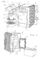
- FIG. 1 shows a system 1,2 according to the invention. This system includes:
- first machine 1 typically includes one or more of the following components:
- the heater may be a thermoblock or an on demand heater (ODH), for instance an ODH type disclosed in EP 1 253 844 , EP 1 380 243 and EP 1 809 151 .
- ODH on demand heater
- suitable brewing units and capsule management are for example disclosed in WO 2005/004683 , WO2007/135136 and WO 2009/043630 , which are hereby incorporated by way of reference.
- suitable beverage preparation modules are for instance disclosed in WO 2009/074550 and WO 2009/130099 , which are hereby incorporated by way of reference.
- a pair of user-recipient supports 12, 12' can be provided for supporting user-recipients of different heights under beverage outlet 11.
- Upper support 12 is in particular movable, e.g. pivotable about axis 12'', away from under outlet 11 to allow positioning of a larger recipient on support 12' under outlet 11.
- At least one user-recipient support 12,12' may be provided with an arrangement 12''', e.g. a handle, opening or the like, to permit or facilitate manual seizure of the support 12,12' and removal thereof from machine 1.
- support 12,12' is/are mechanically connected to ingredient receptacle 15 and removable from machine 1 and insertable thereinto en bloc.
- Second machine 2 may be arranged to dispense a milk-containing beverage 25''', such as heated and/or frothed milk, via second beverage outlet 21. Details of second machine 2 are for example disclosed in EP 2010 152 557 and EP 2010 152 558 , the contents of which are hereby incorporated by way of reference.
- first and second machines 1,2, when connected together, are configurable so that second outlet 21 is positioned or positionable adjacent to the first outlet 11 to dispense second beverage 25''' onto beverage dispensing area 12 and into a cup or mug 4 when positioned for collecting first beverage 15''' from first beverage outlet 11.
- first and second machines 1,2 are configured so that their outlets 11,21 can be positioned to dispense first and second beverages 15''',25'''into a user-recipient 4 without having to move user-recipient 4 under and between first and second outlets 11,21 for collecting first and second beverages 15''',25'''.
- First and/or second outlets 11,21 is/are typically tubular and generally straight and/or elongated.
- machines 1 and 2 may be connected together: mechanically, e.g. via a mechanical connecting member 3 that has plugs 31 fitting corresponding sockets 18',28' in machines 1,2, in particular in bottom faces of machines 1,2; and/or logically, e.g. via wired or wireless data-interfaces 18,28.
- a data-connection between machines 1,2 may be achieved with any communication standard, e.g. USB, XH, RS232 connections or the like.
- the beverage machines may be mechanically connected together directly, i.e. the structures of the machines are mechanically joined, e.g. with a reversible clip mechanism, without any separate intermediate element such as connecting member 3.
- second machine 2 comprises a milk supply arrangement 22,23, in particular a milk reservoir comprising a cooling cavity 22 containing a removable milk tank 23.
- Cooling cavity 22 has insulting walls and an insulating door 221 cooperating with one or more cooling elements, typically including a heat evacuation ventilation system 222. Cooling cavity 22 may be maintained at about 5°C.
- second machine 2 may include an arrangement 24,26 for frothing and/or heating milk 25 from milk supply arrangement 22,23.
- Frothing and/or heating arrangement 24,26 can comprise a steam generator in the form of a boiler 26.
- a pump 26' is configured for circulating water from a water reservoir 27' into steam generator 26.
- Steam 25' generated in generator 26 is mixed with milk 25 and optionally with air 25", in particular within a venturi device 24 in or upstream outlet 21. Frothed and/or heated milk 25''' is dispensed via outlet 21.
- second machine 2 can have a collector reservoir 27 for collecting a cleaning liquid 25', e.g. hot water and/or steam 25', circulated through the frothing and/or heating arrangement 24,26.
- the cleaning liquid may be generated by boiler 26 fed with water from reservoir 27' via pump 26'.
- Collector reservoir 27 and supply reservoir 27' may be adjacent to each other, in particular formed as a single component with two compartments defining reservoirs 27,27', and/or insertable into machine 2 and/or removable therefrom as a drawer, e.g. a bottom drawer of machine 2.
- Second outlet 21 can be movable, e.g. pivotable, between: an operative position for dispensing the second beverage 25''' onto the beverage dispensing area 12,12', e.g. the appropriate user-recipient support; and a distant position, such as a rest or service position on a docket station 211.
- Docket station 211 may have a collar 211' to receive outlet 21 in the distant position.
- Collar 211' may serve to stop the return movement of outlet 21 and/or confine circulation of liquid from outlet 21 into docket station 211.
- outlet 21 is off-set relative to main body 2' of machine 2, in particular on the side of body 2', and located over the dispensing area defined by cup support(s) 12,12' of machine 1.
- the distant position of outlet 21 is aligned with main body 2', in particular in front of body 2', as shown in Fig 2 .
- Outlet 21 can be pivotally mounted on main body 2' so as to be movable between the operative position and the distant position.
- second machine 2 can be prevented from dispensing second beverage 25''' when second outlet 21 is in the distant position.
- second machine can be prevented from carrying out a cleaning process when second outlet 21 is away from the distant position, in particular when second outlet 21 is in the operative position.
- One or more sensors may be provided to detect the position of outlet 21, in particular when outlet 21 is in the distant position and/or in the operative position.
- Docket station 211 may be in fluid communication, e.g. via an inner duct, with collector reservoir 27 so as to collect cleaning liquid from outlet 21 and evacuate the liquid into reservoir 27.
- second outlet 21 may be movable only manually into the operative position above recipient 4.
- a return of outlet 21 into a distant position e.g. on docket station 211 may be automatic, e.g. via an actuator in the form of an internal spring 212 that is stressed by manually moving second outlet 21 into the operative position and that drives second outlet 21 from the operative position into the distant position by relaxing.
- the actuator may be configured to return outlet 21 automatically at an end of a beverage dispensing process of second machine 2.
- outlet 21 cooperates with a locking device that locks outlet 21 in the dispensing position.
- the locking device may lock outlet 21 in the dispensing position until beverage dispensing is completed or until return is requested by a user or otherwise needed, e.g. for service purposes, and then the locking device releases outlet 21 to allow the automatic return.
- an electric motor as an actuator to move automatically the second outlet between the dispensing position and the distant position.
- the second outlet may be moved automatically into the dispensing position, a collision sensor being preferably provided, e.g. mechanically or optically, to detected and prevent any collision between a user-recipient and the second outlet when moving to the dispensing position.
- first machine 1 can comprise a first control module 19' for controlling preparation of first beverage 15''' and the second machine may include a second control module 29' for controlling the preparation of second beverage 25'''.
- First and second control modules 19', 29' can be in direct or indirect data-communication when second machine 2 is connected to first machine 1, e.g. via corresponding data-interfaces 18,28.
- first and second control modules 19',29' may be in data-communication to coordinate dispensing of first and second beverages 15''',25''' via first and second outlets 11,21.
- First and second control modules 19',29' may be arranged to coordinate and dispense, in particular successively, first and second beverages 15''', 25''' on a single user-request of a combined beverage of first and second beverages 15''',25''', in particular via a single user-actuation of a user-interface 1A, 2A of the first or the second machine 1,2.
- first and second control modules 19', 29' are arranged to provide information to a user via a user-interface 2B that is integrated in second machine 2.
- interface 2B is a screen or touch-screen or another device for providing visual and/or sound signals to a user.
- a user when machines 1,2 are connected via interfaces 18,28, a user will have the option of requesting: a first beverage only, a second beverage only, or a combination of first and second beverages.
- a combination beverage may be requested via user-selector 2A of second machine 2.
- a proper coordination of control units 19', 29' e.g. one control unit operating as a master and the other control unit operating as a slave, will lead to the coordinated control of machines 1,2 and dispensing of beverages 15''', 25''' via outlets 11,21, as desired by a user. It is also possible that, when connected together, only one of user-interfaces 1A, 2B remains active.
- machine 2 further includes a feed-back panel 2B, e.g. a screen for providing information on a beverage preparation process and/or the status of machine 2 and/or machine 1, e.g. the temperature or availability of milk in tank 23.
- a feed-back panel 2B e.g. a screen for providing information on a beverage preparation process and/or the status of machine 2 and/or machine 1, e.g. the temperature or availability of milk in tank 23.
- first machine 1 When first and second machines 1,2 are disconnected, first machine 1 can be arranged to prepare and dispense first beverage 15''' and/or second machine 2 can be arranged to prepare second beverage 25'''.
- machines 1,2 may be used in combination or separately to prepare a beverage 15''', 25'''.
- First and second machines 1,2 may have each a power connection 19,29 for separate connection to a power supply, e.g. to the mains. Electric cords may be used to connect each connector 19,29.
- An arrangement 191 may be provided to guide and/or secure such an electric cord on a face of machine 1, e.g. on a bottom face thereof.
- a similar arrangement 181 may be provided for a data-transmission cable connecting connectors 18,28.
Abstract
A beverage preparation system (1,2,3) comprises:
- a first machine (1) for preparing a first beverage (15'''), the first machine having a first outlet (11) for dispensing a beverage, such as coffee, onto a beverage dispensing area (12) for positioning a cup or mug (4); and
- a second machine (2) for preparing and dispensing a second beverage (25''') via a second beverage outlet ( 2 1 ) , the second machine being disconnectably connected to the first machine and separable therefrom.
The first and second machines (1,2), when connected, are configurable so that the second outlet (21) is positioned or positionable adjacent to the first outlet (11) to dispense the second beverage (25''') onto the beverage dispensing area (12) and into a cup or mug (4) in position for collecting the first beverage (15''') from the first beverage outlet.
Description
- The field of the invention pertains to beverage dispensing systems having a first beverage preparation machine and a second beverage preparation machine, in particular at least one of the machines is configured for preparing a beverage from an ingredient capsule.
- For the purpose of the present description, a "beverage" is meant to include any human-consumable liquid substance, such as tea, hot or cold coffee, hot or cold chocolate, hot or cold milk, soup, baby food, hot or cold water, etc... A "capsule" is meant to include any pre-portioned beverage ingredient within an enclosing packaging of any material, in particular an airtight packaging, e.g. plastic, aluminium, recyclable and/or biodegradable packagings, and of any shape and structure, including soft pods or rigid cartridges containing the ingredient.
- Certain beverage preparation machines use capsules containing ingredients to be extracted or to be dissolved; for other machines, the ingredients are stored and dosed automatically in the machine or else are added at the time of preparation of the drink.
- Most coffee machines possess within a housing: filling means that include a pump for liquid, usually water, which pumps the liquid from a source of water that is cold or indeed heated through heating means, such as a heating resistor, a thermoblock or the like.
-
EP 1 864 598 -
EP 1 878 368 -
FR 2 544 185WO 2009/074550 . - Likewise,
US 6,029,622 discloses a coffee dispensing system having three units made up of two coffee dispensing towers and a warming base mounted side-by-side to one another. The first dispensing tower is adapted for large airpot vessels. The second dispensing tower is adapted for cups. The warming base adjacent to the dispenser towers is configured for maintaining coffee in an airpot vessel or in a cup warm. The dispensing system is powered via a power cord connected to the mains. The dispensing unit and warming base have an internal power interconnection or can be interconnected externally via power cords. Each tower or warming base has its own power switch. The second dispensing tower may be substituted by a coffee grinder or another accessory or attachment. - There are also coffee machines that have an integrated milk frother for the preparation of milk-containing coffee, e.g. cappuccino. For instance, the milk-frother is arranged to intake fresh milk from a milk container and mix the milk with air and steam within a venturi device to dispense via an outlet froth into a user-mug. Examples of such devices are disclosed in
EP 0 791 321 ,EP 1 830 683EP 1 764 014 -
WO 2009/074555 discloses a system including a coffee preparation machine that has a platform for receiving a removable milk-frothing jug. The milk-frothing device is powered via a disconnectable strix-type connection from the platform and can be removed therefrom for pouring frothed milk into a recipient. - Despite all the above developments, there is still a need to increase the versatility of beverage machines.
- The invention thus relates to a beverage preparation system having a plurality of beverage preparation machines. For instance, such a machine is a coffee, tea, chocolate, cacao, milk or soup preparation machine.
- In particular, the system comprises a first beverage machine for preparing a first beverage, the first machine having a first outlet for dispensing a beverage onto a beverage dispensing area for positioning a cup or mug.
- In particular, the first machine is arranged for preparing within a beverage processing module a beverage by passing hot or cold water or another liquid through a capsule containing an ingredient, such as a flavouring ingredient, of the beverage to be prepared, such as ground coffee or tea or chocolate or cacao or milk powder. Such a beverage preparation module is for example disclosed in
WO 2009/074550 . - The beverage preparation typically includes the mixing of a plurality of beverage ingredients, e.g. water and milk powder, and/or the infusion of a beverage ingredient, such as an infusion of ground coffee or tea with water. For instance, a predetermined amount of beverage is formed and dispensed on user-request, which corresponds to a serving. The volume of such a serving may be in the range of 25 to 200 ml, e.g. the volume for filling a cup or mug, depending on the type of beverage. Formed and dispensed beverages may be selected from ristrettos, espressos, lungos, cappuccinos, café latte, americano coffees, teas, etc... In particular, a coffee machine may be configured for dispensing espressos, e.g. an adjustable volume of 20 to 60 ml per serving, and/or for dispensing lungos, e.g. a volume in the range of 70 to 150 ml per serving.
- The system comprises a second machine for preparing and dispensing a second beverage via a second beverage outlet. Typically, the second beverage prepared and dispensed by the second machine is mixable with the first beverage to modify the taste thereof. For instance, frothed or non-frothed, heated or non-heated milk may be dispensed as a second beverage to be mixed with a first beverage selected from coffee, chocolate or tea. Other beverage combinations are contemplated, e.g. involving syrup or sweeteners. Milk heating and/or frothing arrangements are known in the art, e.g. using a venturi system and/or a whisk, as for example disclosed in the abovementioned
EP 0 791 321 ,EP 1 830 683EP 1 764 014WO 2009/074555 . - The second machine is disconnectably connected to the first machine and separable therefrom. The connection may be mechanical, e.g. via a removable connector member such as an removably pluggable connector plate. The connection may be mechanical, to relatively position and secure the first and second machines. The connection may be to transmit power and/or data between the first and second machines. For instance, the first and second machines are connected via a wired, e.g. cable, or wireless, e.g. radio or light, data-transmission in particular of the known type, e.g. USB or XH or JST connection cable and like connections.
- The connection is designed to be disconnectable by a user normally operating the machine, i.e. without having to dismantle the machines or significant parts thereof requiring intervention of a service person or other specially qualified person. Typically, the connection is removably plugged, clipped, locked or the like preferably in a simple and reliable manner for normal use of the machines. The connection may be direct from one machine to the other, e.g. one machine housing or frame to the other machine housing or frame mechanically and/or logically, or via an active or passive interface device, e.g. via a separate intermediate cable or mechanical connector.
- The machines may be separated for transportation or when only one of the machines is needed. In a particular environment, only the first beverage may be desired so that the second machine dispensing a second beverage becomes superfluous and may be removed or simply not connected to the first machine. Thus, the first and/or the second machine(s) may be operated in a standalone configuration, i.e. without its companion machine, namely the first or second machine as the case may be.
- In accordance with the invention, the first and second machines, when connected, are configurable so that the second outlet is positioned or positionable adjacent to the first outlet to dispense the second beverage onto the said beverage dispensing area and into a cup or mug in position for collecting the first beverage from the first beverage outlet.
- In other words, when the first and second machines are connected, the first and second outlets are positionable sufficiently close to dispense first and second beverages into a cup or mug without having to move the cup or mug from under one outlet to the other outlet during the dispensing of the first and second beverages. Typically, the first and second beverage outlets are relatively positionable to be distant by no more than 5 cm, in particular less than 3 cm, such as less than 2 cm optionally less than 1 cm.
- Dispensing area configurations for placing a user-cup under a beverage outlet are for example disclosed in
EP 1 867 260EP 2 227 122 - As mentioned above, the second machine may be configured to dispense a milk-containing beverage. The second machine may have a milk supply arrangement, in particular a milk reservoir, such as a cooling cavity containing a milk tank. The second machine can include an arrangement for frothing and/or heating milk from said milk supply arrangement. The frothing and/or heating arrangement may comprise a steam generator for mixing the milk with steam and optionally air, in particular within a venturi device. The second machine may have a collector reservoir for collecting a cleaning liquid circulated through the frothing and/or heating arrangement, the cleaning liquid being in particular generated by a steam generator and then typically circulated along a milk path for cleaning thereof.
- The second outlet can be movable between an operative position for dispensing the second beverage onto the beverage dispensing area, e.g. into a user-cup, and a distant position, such as a rest or service position. The second machine is in particular prevented from dispensing the second beverage when the second outlet is in the distant position, namely away from the dispensing area where the user-cup is supposed to be placed.
- The second outlet can be movable only manually into the operative position. Such a configuration is desirable when there is a risk of collision between the second outlet and a cup that is improperly positioned on the dispensing area or of inappropriate dimensions so that it would interfere with the moving beverage outlet. By avoiding automatic movement of the beverage outlet into the operative position, there is no risk of unwanted collision between the outlet and the cup.
- Conversely, the return of the outlet may be automatic if proper positioning and appropriate dimensions of the cup in the beverage dispensing area is ascertained. Hence, the second machine may comprise an actuator for automatically returning the second outlet from the operative position into the distant position, in particular at an end of a beverage dispensing process of the second machine, e.g. a serving of the second beverage. For example, the actuator comprises a spring that is stressed by manually moving the second outlet into the operative position and that drives the second outlet from the operative position into said distant position by relaxing. The spring may be of any kind appropriate to a particular configuration of the second machine, e.g. a traction, compression or flexion spring, a helicoidal, spiral or blade spring.
- Typically, the first machine has a first control module for controlling the preparation of the first beverage. The second machine may have a second control module for controlling the preparation of the second beverage. These first and second control modules can be in direct or indirect data-communication when the second machine is connected to the first machine. Wired or wireless data-communication may be provided, for instance via a data-communication cable and/or via a USB or XH data-interface or similar means, e.g. RS232, etc...
- In a particular embodiment, the first and second control modules are in data-communication to coordinate dispensing of said first and second beverages via the first and second outlets. The first and second control modules may be arranged to coordinate and dispense, in particular successively, these first and second beverages on a single user-request of a combined beverage of the first and second beverages, in particular via a single user-actuation of an user-interface of the first or the second control module. For instance, the first machine or the second machine has a user-selector, e.g. a button, for requesting a beverage combining the first and second beverages. Thus, a combined beverage prepared by the first and second machines may be requested by a single user-touch of the appropriate user-interface.
- Likewise, the first and second control modules may be arranged to provide information to a user via a user-interface that is integrated either in the first machine or in the second machine.
- Such first and second machines can be disconnected, the first machine being arranged to prepare and dispense the first beverage and/or the second machine being arranged to prepare the second beverage. Hence, the first and/or second machines may be configured to operate both within the system, i.e. connected to the companion machine of the system, and in a standalone configuration, i.e. disconnected from the companion machine of the system, for instance when only the first or the second beverage is desired and/or requestable.
- The first and the second machines may have each a power connection for separate connection to a power supply, e.g. to the mains. Thus separate powering of the machines is possible which allows a standalone operation of each of the first and second machines.
- The invention also relates to a second machine for preparing a second beverage. The second machine has: a second control module and a second outlet for dispensing a second beverage onto a beverage dispensing area for positioning a user-recipient; and a connector disconnectably connectable to a first machine for preparing and delivering a first beverage, the first machine having a first control module.
- The second control module is arranged to be in data-communication with said first module to coordinate and dispense, in particular successively, said first and second beverages on a single user-request of a combined beverage of said first and second beverages, in particular via a single user-actuation of an user-interface of the first or the second control module.
- The second machine may further include any of the abovementioned feature relating to the above second machine and/or a combination of such features.
- The invention will now be described with reference to the schematic drawings, wherein:
-
Figure 1 illustrates a system according to the invention having a first beverage machine and a second beverage machine; -
Figure 2 is a perspective front view of this second beverage machine; -
Figure 3 is a perspective view from below of the first beverage machine shown inFig. 1 ; -
Figure 4 is a perspective view from behind of the second beverage machine shown inFigs 1 and 2 ; and -
Figure 5 shows a mechanical connector for mechanically connecting the first and second machines. -
Figure 1 shows asystem - a
first machine 1 for preparing and dispensing a first beverage 15''' via afirst outlet 11 onto abeverage dispensing area 12 for positioning a cup ormug 4; and - a
second machine 2 for preparing and dispensing a second beverage 25''' via asecond beverage outlet 21, the second machine being disconnectably connected to the first machine and separable therefrom. - As illustrated in
Figs 1 and3 ,first machine 1 typically includes one or more of the following components: - a) a
module 13, e.g. a brewing unit, delimiting in a processing position an inner flavouring chamber for receiving an ingredient of beverage 15''' such as a flavouring ingredient, in particular a pre-portioned ingredient supplied within a capsule, and for guiding via an inlet an incoming flow of liquid for flavouring thereof, such as water, through this ingredient tobeverage outlet 11; - b) a
handle 1B for bringingmodule 13 from this processing position into a transfer position and/or vice versa, the transfer position allowing insertion, e.g. fromoutside machine 1 via a capsule insertion slot 13', of such ingredient intomodule 13 and/or removal therefrom of said ingredient; - c) a user-
interface 1A for allowing a user to request a beverage preparation, e.g. two or three different beverage preparations such as espresso or regular or lungo coffee, and/or ahot water switch 1C for dispensing hot water, and/or a master switch (main power switch) for switchingmachine 1 on and/or off; - d) an in-line heater, such as a thermoblock, for heating this flow of liquid to be supplied to the flavouring chamber of
module 13; - e) a pump for pumping liquid through the in-line heater;
- f) one or more fluid connecting members for guiding liquid from a source of liquid, such as
tank 14 of liquid, tomodule 13; - g) an electric control unit 19' (in dotted lines in
Fig. 3 ), in particular comprising a printed circuit board (PCB), for receiving instructions from a user via input user-interface 1A and for controlling the in-line heater and the pump; - h) one or more sensors for sensing at least one characteristic selected from characteristics of
module 13, the in-line heater, the pump,liquid tank 14, aningredient receptacle 15, a flow of the liquid (e.g. by a flowmeter), a pressure of the liquid and a temperature of the liquid, and for communicating such characteristic(s) to control unit 19'; and/or - i) one or more user-recipient supports 12, 12' delimiting a beverage dispensing area for positioning a user-
recipient 4 underoutlet 11. - The heater may be a thermoblock or an on demand heater (ODH), for instance an ODH type disclosed in
EP 1 253 844EP 1 380 243EP 1 809 151WO 2005/004683 ,WO2007/135136 andWO 2009/043630 , which are hereby incorporated by way of reference. Suitable beverage preparation modules are for instance disclosed inWO 2009/074550 andWO 2009/130099 , which are hereby incorporated by way of reference. - A pair of user-recipient supports 12, 12' can be provided for supporting user-recipients of different heights under
beverage outlet 11.Upper support 12 is in particular movable, e.g. pivotable about axis 12'', away from underoutlet 11 to allow positioning of a larger recipient on support 12' underoutlet 11. At least one user-recipient support 12,12' may be provided with an arrangement 12''', e.g. a handle, opening or the like, to permit or facilitate manual seizure of thesupport 12,12' and removal thereof frommachine 1. For instance,support 12,12' is/are mechanically connected toingredient receptacle 15 and removable frommachine 1 and insertable thereinto en bloc. - Further details of the flow circuit and structure and operation of such a
machine 1 are for example disclosed inPCT/EP10/064772 PCT/EP10/064773 PCT/EP10/068580 EP 2010 152 556 EP 2010 163 649 EP 2010 169 201 EP 2010 169 766 EP 2010 175 544 -
Second machine 2 may be arranged to dispense a milk-containing beverage 25''', such as heated and/or frothed milk, viasecond beverage outlet 21. Details ofsecond machine 2 are for example disclosed inEP 2010 152 557 EP 2010 152 558 - In accordance with the invention, first and
second machines second outlet 21 is positioned or positionable adjacent to thefirst outlet 11 to dispense second beverage 25''' ontobeverage dispensing area 12 and into a cup ormug 4 when positioned for collecting first beverage 15''' fromfirst beverage outlet 11. - Hence, first and
second machines outlets recipient 4 without having to move user-recipient 4 under and between first andsecond outlets second outlets - As shown in
Figs 3 to 5 ,machines member 3 that has plugs 31 fitting corresponding sockets 18',28' inmachines machines interfaces machines member 3. - As shown in
Figs 1, 2 and4 ,second machine 2 comprises amilk supply arrangement cooling cavity 22 containing aremovable milk tank 23. Coolingcavity 22 has insulting walls and an insulatingdoor 221 cooperating with one or more cooling elements, typically including a heatevacuation ventilation system 222. Coolingcavity 22 may be maintained at about 5°C. - Furthermore, as schematically illustrated in dotted lines in
Fig. 1 ,second machine 2 may include anarrangement 24,26 for frothing and/orheating milk 25 frommilk supply arrangement heating arrangement 24,26 can comprise a steam generator in the form of a boiler 26. A pump 26' is configured for circulating water from a water reservoir 27' into steam generator 26. Steam 25' generated in generator 26 is mixed withmilk 25 and optionally withair 25", in particular within aventuri device 24 in orupstream outlet 21. Frothed and/or heated milk 25''' is dispensed viaoutlet 21. - Moreover,
second machine 2 can have acollector reservoir 27 for collecting a cleaning liquid 25', e.g. hot water and/or steam 25', circulated through the frothing and/orheating arrangement 24,26. The cleaning liquid may be generated by boiler 26 fed with water from reservoir 27' via pump 26'.Collector reservoir 27 and supply reservoir 27' may be adjacent to each other, in particular formed as a single component with twocompartments defining reservoirs 27,27', and/or insertable intomachine 2 and/or removable therefrom as a drawer, e.g. a bottom drawer ofmachine 2. -
Second outlet 21 can be movable, e.g. pivotable, between: an operative position for dispensing the second beverage 25''' onto thebeverage dispensing area 12,12', e.g. the appropriate user-recipient support; and a distant position, such as a rest or service position on adocket station 211.Docket station 211 may have a collar 211' to receiveoutlet 21 in the distant position. Collar 211' may serve to stop the return movement ofoutlet 21 and/or confine circulation of liquid fromoutlet 21 intodocket station 211. - As illustrated in
Fig. 1 , the operative position ofoutlet 21 is off-set relative to main body 2' ofmachine 2, in particular on the side of body 2', and located over the dispensing area defined by cup support(s) 12,12' ofmachine 1. The distant position ofoutlet 21 is aligned with main body 2', in particular in front of body 2', as shown inFig 2 .Outlet 21 can be pivotally mounted on main body 2' so as to be movable between the operative position and the distant position. - In particular,
second machine 2 can be prevented from dispensing second beverage 25''' whensecond outlet 21 is in the distant position. Likewise, second machine can be prevented from carrying out a cleaning process whensecond outlet 21 is away from the distant position, in particular whensecond outlet 21 is in the operative position. One or more sensors may be provided to detect the position ofoutlet 21, in particular whenoutlet 21 is in the distant position and/or in the operative position.Docket station 211 may be in fluid communication, e.g. via an inner duct, withcollector reservoir 27 so as to collect cleaning liquid fromoutlet 21 and evacuate the liquid intoreservoir 27. - To avoid any undesired collision with an improperly placed user-
recipient 4,second outlet 21 may be movable only manually into the operative position aboverecipient 4. A return ofoutlet 21 into a distant position, e.g. ondocket station 211 may be automatic, e.g. via an actuator in the form of aninternal spring 212 that is stressed by manually movingsecond outlet 21 into the operative position and that drivessecond outlet 21 from the operative position into the distant position by relaxing. The actuator may be configured to returnoutlet 21 automatically at an end of a beverage dispensing process ofsecond machine 2. For example,outlet 21 cooperates with a locking device that locksoutlet 21 in the dispensing position. The locking device may lockoutlet 21 in the dispensing position until beverage dispensing is completed or until return is requested by a user or otherwise needed, e.g. for service purposes, and then the lockingdevice releases outlet 21 to allow the automatic return. In a variation, it is also possible to provide an electric motor as an actuator to move automatically the second outlet between the dispensing position and the distant position. The second outlet may be moved automatically into the dispensing position, a collision sensor being preferably provided, e.g. mechanically or optically, to detected and prevent any collision between a user-recipient and the second outlet when moving to the dispensing position. - As mentioned above,
first machine 1 can comprise a first control module 19' for controlling preparation of first beverage 15''' and the second machine may include a second control module 29' for controlling the preparation of second beverage 25'''. First and second control modules 19', 29' can be in direct or indirect data-communication whensecond machine 2 is connected tofirst machine 1, e.g. via corresponding data-interfaces second outlets interface second machine interface 2B that is integrated insecond machine 2. For instance,interface 2B is a screen or touch-screen or another device for providing visual and/or sound signals to a user. - For example, when
machines interfaces selector selector 2A ofsecond machine 2. A proper coordination of control units 19', 29', e.g. one control unit operating as a master and the other control unit operating as a slave, will lead to the coordinated control ofmachines outlets interfaces - As illustrated in
Fig. 1 ,machine 2 further includes a feed-back panel 2B, e.g. a screen for providing information on a beverage preparation process and/or the status ofmachine 2 and/ormachine 1, e.g. the temperature or availability of milk intank 23. - When first and
second machines first machine 1 can be arranged to prepare and dispense first beverage 15''' and/orsecond machine 2 can be arranged to prepare second beverage 25'''. Hence,machines - First and
second machines power connection connector arrangement 191 may be provided to guide and/or secure such an electric cord on a face ofmachine 1, e.g. on a bottom face thereof. Likewise, asimilar arrangement 181 may be provided for a data-transmissioncable connecting connectors
Claims (15)
- A beverage preparation system (1,2,3) comprising: a first machine (1) for preparing and dispensing a first beverage (15'''), such as coffee, via a first outlet (11) onto a beverage dispensing area (12) for positioning a cup or mug (4); and a second machine (2) for preparing and dispensing a second beverage (25''') via a second beverage outlet (21), the second machine being disconnectably connected to the first machine and separable therefrom,
characterised in that the first and second machines (1,2), when connected, are configurable so that the second outlet (21) is positioned or positionable adjacent to the first outlet (11) to dispense said second beverage (25''') onto said beverage dispensing area (12) and into a cup or mug (4) in position for collecting said first beverage (15''') from the first beverage outlet. - The system of claim 1, wherein the second machine (2) comprises a milk supply arrangement (22,23), in particular a milk reservoir comprising a cooling cavity (22) containing a milk tank (23).
- The system of claim 2, wherein the second machine comprises an arrangement (24,26) for frothing and/or heating milk (25) from said milk supply arrangement (22,23), the frothing and/or heating arrangement (24,26) comprising in particular a steam generator (26) for mixing steam (25') into said milk (25) and optionally air (25''') , such as within a venturi device (24).
- The system of claim 3, wherein the second machine (2) comprises a collector reservoir (27) for collecting a cleaning liquid (25') circulated through the frothing and/or heating arrangement (24,26), the cleaning liquid being in particular generated by a steam generator (26) optionally fed with water from a source (27') via a pump (26''') .
- The system of any preceding claim, wherein the second beverage outlet (21) is movable between an operative position for dispensing said second beverage (25''') onto said beverage dispensing area (12) and a distant position, such as a rest or service position optionally on a docket station (211), the second machine (2) being in particular prevented from dispensing said second beverage (25''') when the second outlet is in the distant position.
- The system of claim 5, wherein the second outlet (21) is movable manually into the operative position, in particular only manually into the operative position.
- The system of claim 5 or 6, wherein the second outlet is movable automatically, in particular by a motor, into the operative position.
- The system of any one of claims 5 to 7, wherein the second machine (2) comprises an actuator (212) for automatically returning the second outlet (21) from the operative position into the distant position, in particular at an end of a beverage dispensing process of the second machine, the actuator optionally comprising a spring (212) that is stressed by manually or automatically moving the second outlet (21) into the operative position and that drives the second outlet from the operative into the distant position by relaxing.
- The system of any preceding claim, wherein the first and second machines (2) are directly or indirectly rigidly connected by a disconnectable mechanical link, in particular by connectable connectors (18',28') integrated in the machines (1,2) and optionally by a separate mechanical intermediate connector (3,31).
- The system of any preceding claim, wherein the first machine (1) comprises a first control module (19') for controlling preparation of said first beverage (15''') and wherein the second machine (2) comprises a second control module (29') for controlling the preparation of said second beverage (25'''), the first and second control modules being in direct or indirect data-communication when the second machine is connected to the first machine, in particular via corresponding data-interfaces (18,28) .
- The system of claim 10, wherein the first and second control modules (19',29') are in data-communication to coordinate dispensing of said first and second beverages (15''',25''') via the first and second outlets (11, 21).
- The system of claim 11, wherein the first and second control modules (19',29') are arranged to coordinate and dispense, e.g. successively, said first and second beverages (15''', 25''') on a single user-request of a combined beverage of said first and second beverages, in particular via a single user-actuation of a user-interface (1A, 2A) of the first or second machine (1,2).
- The system of claim 11 or 12, wherein the first and second control modules (19',29') are arranged to provide information to a user via a user-interface (2B) that is integrated either in the first machine (1) or in the second machine (2).
- The system of any preceding claim, wherein at least one of said first and second machines (1,2) are configured for beverage preparation and dispensing when the first and second machines are disconnected, in particular the first and the second machines having each a power connection (19,29) for separate connection to a power supply, e.g. to the mains, and autonomous operation.
- A second machine (2) for preparing a second beverage (25''') having:- a second control module (29') and a second outlet (21) for dispensing a second beverage (25''') onto a beverage dispensing area (12) for positioning a user-recipient (4); and- a connector (28) disconnectably connectable to a first machine (1) for preparing and delivering a first beverage (15'''), said first machine having a first control module (19'),
characterised in that the second control module (29') is arranged to be in data-communication with said first module (19') to coordinate and dispense, in particular successively, said first and second beverages (15"', 25''') on a single user-request of a combined beverage of said first and second beverages, in particular via a single user-actuation of a user-interface (1A, 2A) of the first or the second machine (1,2).
Priority Applications (10)
| Application Number | Priority Date | Filing Date | Title |
|---|---|---|---|
| EP11150389A EP2474254A1 (en) | 2011-01-07 | 2011-01-07 | Modular beverage dispensing system |
| US13/978,652 US10178925B2 (en) | 2011-01-07 | 2012-01-05 | Modular beverage dispensing system |
| AU2012204899A AU2012204899B2 (en) | 2011-01-07 | 2012-01-05 | Modular beverage dispensing system |
| BR112013017437A BR112013017437A2 (en) | 2011-01-07 | 2012-01-05 | modular beverage dispensing system |
| EP12700014.9A EP2661201A1 (en) | 2011-01-07 | 2012-01-05 | Modular beverage dispensing system |
| CN201280004855.0A CN103298383B (en) | 2011-01-07 | 2012-01-05 | Modular beverage distribution system |
| PCT/EP2012/050144 WO2012093157A1 (en) | 2011-01-07 | 2012-01-05 | Modular beverage dispensing system |
| JP2013547858A JP5963771B2 (en) | 2011-01-07 | 2012-01-05 | Modular beverage supply system |
| CA2821826A CA2821826A1 (en) | 2011-01-07 | 2012-01-05 | Modular beverage dispensing system |
| RU2013136827/12A RU2583904C2 (en) | 2011-01-07 | 2012-01-05 | Modular beverage dispensing system |
Applications Claiming Priority (1)
| Application Number | Priority Date | Filing Date | Title |
|---|---|---|---|
| EP11150389A EP2474254A1 (en) | 2011-01-07 | 2011-01-07 | Modular beverage dispensing system |
Publications (1)
| Publication Number | Publication Date |
|---|---|
| EP2474254A1 true EP2474254A1 (en) | 2012-07-11 |
Family
ID=44260397
Family Applications (2)
| Application Number | Title | Priority Date | Filing Date |
|---|---|---|---|
| EP11150389A Withdrawn EP2474254A1 (en) | 2011-01-07 | 2011-01-07 | Modular beverage dispensing system |
| EP12700014.9A Withdrawn EP2661201A1 (en) | 2011-01-07 | 2012-01-05 | Modular beverage dispensing system |
Family Applications After (1)
| Application Number | Title | Priority Date | Filing Date |
|---|---|---|---|
| EP12700014.9A Withdrawn EP2661201A1 (en) | 2011-01-07 | 2012-01-05 | Modular beverage dispensing system |
Country Status (9)
| Country | Link |
|---|---|
| US (1) | US10178925B2 (en) |
| EP (2) | EP2474254A1 (en) |
| JP (1) | JP5963771B2 (en) |
| CN (1) | CN103298383B (en) |
| AU (1) | AU2012204899B2 (en) |
| BR (1) | BR112013017437A2 (en) |
| CA (1) | CA2821826A1 (en) |
| RU (1) | RU2583904C2 (en) |
| WO (1) | WO2012093157A1 (en) |
Cited By (4)
| Publication number | Priority date | Publication date | Assignee | Title |
|---|---|---|---|---|
| CN103960973A (en) * | 2013-01-30 | 2014-08-06 | 广州市拓璞电器发展有限公司 | Combined device of coffee machine and milk foaming machine |
| WO2016193223A1 (en) | 2015-05-29 | 2016-12-08 | Illycaffe' S.P.A. Con Unico Socio | Modular machine for preparing beverages from capsules |
| WO2017046230A1 (en) * | 2015-09-18 | 2017-03-23 | Franke Kaffeemaschinen Ag | Cleaning system for an apparatus for dispensing liquid foodstuffs |
| CH713954A1 (en) * | 2017-07-06 | 2019-01-15 | Steiner Ag Weggis | Milk module for producing milk foam or milk drinks, preferably for installation in a coffee machine. |
Families Citing this family (39)
| Publication number | Priority date | Publication date | Assignee | Title |
|---|---|---|---|---|
| EP2474254A1 (en) * | 2011-01-07 | 2012-07-11 | Nestec S.A. | Modular beverage dispensing system |
| US10980368B2 (en) * | 2013-11-29 | 2021-04-20 | Steiner Ag Weggis | Device for pouring out milk froth, liquids or the like |
| USD734634S1 (en) | 2014-03-13 | 2015-07-21 | Megatrade International, Inc. | Dispenser |
| WO2015173100A1 (en) * | 2014-05-13 | 2015-11-19 | Nestec S.A. | Beverage preparation device for hot and cold beverages |
| EP2965671B1 (en) * | 2014-07-07 | 2018-02-28 | De'Longhi Appliances S.r.l. | Milk container that can be associated with a coffee machine and coffee machine having such a milk container |
| WO2016005304A1 (en) * | 2014-07-07 | 2016-01-14 | De' Longhi Appliances S.R.L. | Milk container that can be associated with a coffee machine and coffee machine having such a milk container |
| EP3166458B1 (en) * | 2014-07-09 | 2021-05-05 | Société des Produits Nestlé S.A. | Coupling of a device for connecting a beverage machine to a distribution network |
| DE102014215689A1 (en) * | 2014-08-07 | 2016-02-11 | Franke Kaffeemaschinen Ag | Supply unit for supplying a liquid food to a beverage dispenser and method for cleaning at least one feed unit for supplying a liquid food to a beverage dispenser |
| US9844293B2 (en) | 2015-03-06 | 2017-12-19 | Spectrum Brands, Inc. | Apparatus for dispensing beverages |
| KR102400390B1 (en) * | 2015-03-17 | 2022-05-19 | 엘지전자 주식회사 | Drink Machine |
| US10913647B2 (en) | 2015-06-11 | 2021-02-09 | LifeFuels, Inc. | Portable system for dispensing controlled quantities of additives into a beverage |
| WO2017019812A1 (en) * | 2015-07-28 | 2017-02-02 | Camellia Labs Inc | Apparatus and method for making tea latte |
| PT3344098T (en) * | 2015-09-04 | 2019-09-23 | Nestle Sa | Beverage machine with an ergonomic user-interface |
| US20170095105A1 (en) * | 2015-10-05 | 2017-04-06 | Joseph R. Clark | Mini steam generator for cooking food, modular cooking appliance, and modular food preparation station |
| AU2016343218A1 (en) * | 2015-10-23 | 2018-03-08 | Société des Produits Nestlé S.A. | Expandable functionality beverage preparation machine |
| AU2016342223A1 (en) * | 2015-10-23 | 2018-03-08 | Société des Produits Nestlé S.A. | Beverage system |
| NL2016403B1 (en) * | 2016-03-09 | 2017-09-26 | Douwe Egberts Bv | Assembly and method for frothing fluid. |
| NL2016400B1 (en) | 2016-03-09 | 2017-09-26 | Douwe Egberts Bv | Assembly and method for frothing milk. |
| CA3016105A1 (en) | 2016-04-07 | 2017-10-12 | Nestec S.A. | Beverage preparation machine with two-liquid circuits and electronic device for controlling the same |
| US11378463B2 (en) | 2016-08-10 | 2022-07-05 | Breville Pty Limited | Sensor mounting assembly |
| BR112019008836A2 (en) | 2016-11-09 | 2019-07-09 | Pepsico Inc | carbonated beverage manufacturing sets, methods, and systems |
| US10898031B2 (en) * | 2016-11-16 | 2021-01-26 | F'real Foods Llc | Modular blender with improved water heating and light beam detection |
| EP3340195A1 (en) * | 2016-12-23 | 2018-06-27 | Qbo Coffee GmbH | Method for operating a machine for making beverages, machine for making beverages and method for operating an operator panel |
| IT201700070372A1 (en) * | 2017-06-23 | 2018-12-23 | De Longhi Appliances Srl | BUILT-IN COFFEE MACHINE |
| CN107536473B (en) * | 2017-08-18 | 2021-02-05 | 湛江市新诺饮料设备制造有限公司 | Milk tea coffee machine and preparation method of outlet beverage thereof |
| CN111107770A (en) * | 2017-09-25 | 2020-05-05 | 雀巢产品有限公司 | Beverage machine with modularity |
| ES2956783T3 (en) | 2017-09-25 | 2023-12-28 | Nestle Sa | Beverage machines with removable module |
| US11419449B2 (en) | 2017-12-08 | 2022-08-23 | Societe Des Produits Nestle S.A. | Device for producing milk and/or milk foam and associated system |
| US11337533B1 (en) * | 2018-06-08 | 2022-05-24 | Infuze, L.L.C. | Portable system for dispensing controlled quantities of additives into a beverage |
| US10781093B2 (en) * | 2018-07-23 | 2020-09-22 | Cardomon International Limited | Liquid dispenser for dispensing water and a flavored beverage |
| CN109091003A (en) * | 2018-08-06 | 2018-12-28 | 上海机商实业有限公司 | Automatic vending coffee machine and its method for preparing coffee |
| US20210251419A1 (en) * | 2018-08-09 | 2021-08-19 | Societe Des Produits Nestle S.A. | Easily insertable cup support |
| WO2020064984A1 (en) * | 2018-09-27 | 2020-04-02 | Société des Produits Nestlé SA | Beverage machine with an actuation distribution |
| CN109409996B (en) * | 2018-10-16 | 2022-03-08 | 上海氦豚机器人科技有限公司 | Beverage making system and selling system based on Internet |
| KR102215503B1 (en) * | 2018-12-31 | 2021-02-15 | 제노스전자(주) | Interfacing Device Capable of Setting for Each User |
| US10889424B1 (en) | 2019-09-14 | 2021-01-12 | LifeFuels, Inc. | Portable beverage container systems and methods for adjusting the composition of a beverage |
| US11903516B1 (en) | 2020-04-25 | 2024-02-20 | Cirkul, Inc. | Systems and methods for bottle apparatuses, container assemblies, and dispensing apparatuses |
| CN111932777B (en) * | 2020-07-10 | 2022-09-20 | 江苏蓝天空港设备有限公司 | Multifunctional vending machine |
| US11812892B1 (en) | 2022-04-25 | 2023-11-14 | Sharkninja Operating Llc | Fluid texturing device |
Citations (20)
| Publication number | Priority date | Publication date | Assignee | Title |
|---|---|---|---|---|
| FR2544185A3 (en) | 1983-04-14 | 1984-10-19 | Nuova Faema Spa | Series of modular elements capable of being arranged in various ways in order to make up espresso coffee machines |
| US5498757A (en) * | 1995-04-04 | 1996-03-12 | Boyd Coffee Company | Milk frothing and heating system |
| EP0791321A1 (en) | 1996-02-22 | 1997-08-27 | Gaggia Espanola, SA | Expresso coffee machine provided with a device for whipping milk |
| US6029622A (en) | 1997-08-29 | 2000-02-29 | Mitsubishi Denki Kabushiki Kaisha | Fuel control method and system for cylinder injection type internal combustion engine |
| EP1253844A1 (en) | 2000-01-24 | 2002-11-06 | Societe Des Produits Nestle S.A. | A liquid heating module, a system comprising said module and a process for heating liquid |
| EP1380243A1 (en) | 2002-07-12 | 2004-01-14 | Nestec S.A. | A device for the heating of a liquid |
| WO2005004683A1 (en) | 2003-07-10 | 2005-01-20 | Nestec S.A. | Cap extraction device |
| EP1764014A1 (en) | 2005-09-20 | 2007-03-21 | Nestec S.A. | Thermoblock-based beverage production device with brewing chambers |
| EP1809151A2 (en) | 2004-09-13 | 2007-07-25 | Nestec S.A. | Device and method for heating a liquid |
| EP1830683A2 (en) | 2004-11-11 | 2007-09-12 | Nestec S.A. | Self-cleaning mixing head for producing a milk-based mixture and beverage production machines comprising such a mixing head |
| US20070243305A1 (en) * | 2004-04-21 | 2007-10-18 | Marconi Gian C | Device for Producing a Milk-Based Drink |
| WO2007135136A1 (en) | 2006-05-24 | 2007-11-29 | Nestec S.A. | Brewing device for capsule with closure mechanism of variable transmission ratio |
| EP1864598A1 (en) | 2006-06-09 | 2007-12-12 | Nestec S.A. | Modular beverage production device with docking station |
| EP1867260A1 (en) | 2006-06-16 | 2007-12-19 | Nestec S.A. | Beverage distribution apparatus with support system and droplet recuperation for containers with different sizes |
| EP1878368A1 (en) | 2006-07-11 | 2008-01-16 | Nestec S.A. | Beverage production machine with functional block and support base |
| WO2009043630A2 (en) | 2007-10-04 | 2009-04-09 | Nestec S.A. | Beverage brewing unit |
| EP2070454A1 (en) * | 2007-12-12 | 2009-06-17 | Nestec S.A. | Modular manufacturing of beverage production machines |
| WO2009130099A1 (en) | 2008-04-22 | 2009-10-29 | Nestec S.A. | Modular assembly of a beverage preparation machine |
| US20100212508A1 (en) * | 2009-02-24 | 2010-08-26 | Jura Elektroapparte AG | Dispensing device and coffee machine for milk and milk foam |
| WO2011015963A2 (en) * | 2009-08-03 | 2011-02-10 | Saeco Strategic Services Limited | Coffee machine with a refrigerated compartment |
Family Cites Families (42)
| Publication number | Priority date | Publication date | Assignee | Title |
|---|---|---|---|---|
| IT207919Z2 (en) * | 1986-03-10 | 1988-02-22 | Gaggia Brevetti | ESPRESSO COFFEE MACHINE |
| US4829888A (en) * | 1987-04-23 | 1989-05-16 | Newco Research Corp. | Modularized custom beverage brewer |
| US4892031A (en) * | 1987-04-23 | 1990-01-09 | Newco Research Corporation | Modularized custom beverage brewer |
| IT1230290B (en) * | 1989-07-05 | 1991-10-18 | Nuova Faema Spa | AUTOMATIC MACHINE FOR THE DISPENSING OF COFFEE, CAPPUCCINO AND SIMILAR. |
| US5327815A (en) * | 1991-07-05 | 1994-07-12 | Nestec S.A. | Device for use in beverage extraction machines |
| US5473972A (en) * | 1994-10-24 | 1995-12-12 | Conair Corporation | Milk container attachment for cappucino maker |
| JPH0928572A (en) * | 1995-07-25 | 1997-02-04 | Matsushita Electric Ind Co Ltd | Automatic tea supplying machine |
| US5549036A (en) * | 1995-08-24 | 1996-08-27 | Hourizadeh; Richard | Cappuccino making apparatus |
| US5916351A (en) * | 1995-11-13 | 1999-06-29 | Hamilton Beach--Proctor Silex, Inc. | Modular beverage brewing system with interlocking assembly |
| US6029562A (en) * | 1995-11-13 | 2000-02-29 | Kevin O'Donnell | Modular beverage brewing system with interlocking assembly |
| DE29605821U1 (en) * | 1996-03-28 | 1996-06-20 | Wu Tsann Kuen | Infusion device for a venturi-like device for producing bubbles |
| US5611262A (en) * | 1996-06-24 | 1997-03-18 | Conair Corporation | Cappuccino maker |
| US6095031A (en) * | 1999-01-08 | 2000-08-01 | Bloomfield Industries Canada Limited | Computer controlled brewing apparatus |
| DE19921483C1 (en) * | 1999-05-08 | 2000-08-17 | Braun Gmbh | Appts for foaming milk has a steam pipe with an end jet extending from a base body with a sliding vertical movement in a housing to move the jet in and out of the milk without holding the vessel |
| US6698624B2 (en) * | 2001-04-04 | 2004-03-02 | Nestec S.A. | Device for dispensing a flowable powder substance |
| AU2002259156A1 (en) * | 2001-05-07 | 2002-11-18 | Bunn-O-Matic Corporation | Container positioner |
| RU2331349C2 (en) * | 2003-01-24 | 2008-08-20 | Крафт Фудз Р Унд Д, Инк. | Beverage-making machine |
| DK1472963T3 (en) * | 2003-05-02 | 2009-03-30 | Schaerer Ag M | Device for delivering milk and / or milk foam |
| EP1656866A1 (en) * | 2004-11-12 | 2006-05-17 | Nestec S.A. | Device and method for the preparation of froth from a liquid milk-based food product |
| GB2451005B (en) | 2005-02-28 | 2009-09-23 | Coffee Nation Ltd | Apparatus for preparing beverages |
| US20060254428A1 (en) * | 2005-05-14 | 2006-11-16 | Glucksman Dov Z | Coffee making apparatus |
| ITMI20050880A1 (en) * | 2005-05-16 | 2006-11-17 | Saeco Internat Group S P A | STEAM UNIT WITH EXTERNAL ANCHORING INCLUDING A CARAFE FOR FOAMING MILK AND HEATING DRINKS FOR ESPRESSO DRINKING MACHINE |
| KR20070117945A (en) * | 2006-06-09 | 2007-12-13 | 신장호 | An automatic swing for latter art |
| ITFI20060263A1 (en) * | 2006-10-27 | 2008-04-28 | Saeco Ipr Ltd | EMULSIFIER DEVICE FOR THE PRODUCTION OF FOAMED AND SIMILAR MILK AND RELATIVE METHOD |
| MX2009006983A (en) * | 2006-12-27 | 2009-09-04 | Jura Elektroapparate Ag | Method for dispensing milk portions in drink preparation machines. |
| JP2008194074A (en) | 2007-02-08 | 2008-08-28 | Ryuui Tech Kk | Brewer type coffee machine with nitrogen gas filling function |
| DE202007008813U1 (en) * | 2007-06-21 | 2007-11-29 | Mahlich, Gotthard | The beverage brewer |
| DE202007008814U1 (en) * | 2007-06-21 | 2007-11-29 | Mahlich, Gotthard | Brewing unit of a beverage preparation device |
| WO2009048187A1 (en) * | 2007-10-08 | 2009-04-16 | Kwan Un Baik | Extraction apparatus for use in herb processing in operation of vacuum and low temperature using ultrasonic oscillator |
| ATE505119T1 (en) * | 2007-12-12 | 2011-04-15 | Nestec Sa | CONTAINER FOR USED CAPSULES OR PODS FOR MACHINES FOR PREPARING LIQUIDS OR BEVERAGES |
| DE102008004462A1 (en) | 2008-01-15 | 2009-07-23 | BSH Bosch und Siemens Hausgeräte GmbH | Coffee machine with horizontally movable broth beverage outlet |
| ITFI20080198A1 (en) * | 2008-10-15 | 2010-04-16 | Saeco Ipr Ltd | "COFFEE MACHINE'" |
| DE202009001491U1 (en) * | 2009-02-06 | 2010-06-24 | Melitta Haushaltsprodukte Gmbh & Co. Kommanditgesellschaft | Device for conveying milk |
| DE102009013938A1 (en) * | 2009-03-19 | 2010-09-23 | Niro-Plan Ag | Device for frothing a liquid food in a container |
| IT1394313B1 (en) * | 2009-06-16 | 2012-06-06 | De Longhi Appliances Srl | DEVICE FOR THE PREPARATION OF A MILK BASED DRINK |
| ITFI20090248A1 (en) * | 2009-11-25 | 2011-05-26 | Saeco Ipr Ltd | "COFFEE MACHINE' " |
| PL2345354T3 (en) * | 2010-01-19 | 2013-02-28 | Jura Elektroapparate Ag | Dispensing device for dispensing coffee and/or milk and/or milk foam, beverage making machine with a dispensing device and method for assembling a dispensing device |
| EP2353469A1 (en) * | 2010-02-03 | 2011-08-10 | Nestec S.A. | Beverage preparation machine for large size beverages |
| EP2353474A1 (en) * | 2010-02-03 | 2011-08-10 | Nestec S.A. | Beverage dispenser with safe cleaning arrangement |
| EP2474254A1 (en) * | 2011-01-07 | 2012-07-11 | Nestec S.A. | Modular beverage dispensing system |
| US9507416B2 (en) * | 2011-02-22 | 2016-11-29 | Robert Howard Kimball | Providing a corrected view based on the position of a user with respect to a mobile platform |
| EP2965671B1 (en) * | 2014-07-07 | 2018-02-28 | De'Longhi Appliances S.r.l. | Milk container that can be associated with a coffee machine and coffee machine having such a milk container |
-
2011
- 2011-01-07 EP EP11150389A patent/EP2474254A1/en not_active Withdrawn
-
2012
- 2012-01-05 CA CA2821826A patent/CA2821826A1/en not_active Abandoned
- 2012-01-05 EP EP12700014.9A patent/EP2661201A1/en not_active Withdrawn
- 2012-01-05 WO PCT/EP2012/050144 patent/WO2012093157A1/en active Application Filing
- 2012-01-05 BR BR112013017437A patent/BR112013017437A2/en not_active IP Right Cessation
- 2012-01-05 RU RU2013136827/12A patent/RU2583904C2/en not_active IP Right Cessation
- 2012-01-05 CN CN201280004855.0A patent/CN103298383B/en not_active Expired - Fee Related
- 2012-01-05 US US13/978,652 patent/US10178925B2/en active Active
- 2012-01-05 JP JP2013547858A patent/JP5963771B2/en not_active Expired - Fee Related
- 2012-01-05 AU AU2012204899A patent/AU2012204899B2/en not_active Ceased
Patent Citations (23)
| Publication number | Priority date | Publication date | Assignee | Title |
|---|---|---|---|---|
| FR2544185A3 (en) | 1983-04-14 | 1984-10-19 | Nuova Faema Spa | Series of modular elements capable of being arranged in various ways in order to make up espresso coffee machines |
| US5498757A (en) * | 1995-04-04 | 1996-03-12 | Boyd Coffee Company | Milk frothing and heating system |
| EP0791321A1 (en) | 1996-02-22 | 1997-08-27 | Gaggia Espanola, SA | Expresso coffee machine provided with a device for whipping milk |
| US6029622A (en) | 1997-08-29 | 2000-02-29 | Mitsubishi Denki Kabushiki Kaisha | Fuel control method and system for cylinder injection type internal combustion engine |
| EP1253844A1 (en) | 2000-01-24 | 2002-11-06 | Societe Des Produits Nestle S.A. | A liquid heating module, a system comprising said module and a process for heating liquid |
| EP1380243A1 (en) | 2002-07-12 | 2004-01-14 | Nestec S.A. | A device for the heating of a liquid |
| WO2005004683A1 (en) | 2003-07-10 | 2005-01-20 | Nestec S.A. | Cap extraction device |
| US20070243305A1 (en) * | 2004-04-21 | 2007-10-18 | Marconi Gian C | Device for Producing a Milk-Based Drink |
| EP1809151A2 (en) | 2004-09-13 | 2007-07-25 | Nestec S.A. | Device and method for heating a liquid |
| EP1830683A2 (en) | 2004-11-11 | 2007-09-12 | Nestec S.A. | Self-cleaning mixing head for producing a milk-based mixture and beverage production machines comprising such a mixing head |
| EP1764014A1 (en) | 2005-09-20 | 2007-03-21 | Nestec S.A. | Thermoblock-based beverage production device with brewing chambers |
| WO2007135136A1 (en) | 2006-05-24 | 2007-11-29 | Nestec S.A. | Brewing device for capsule with closure mechanism of variable transmission ratio |
| EP1864598A1 (en) | 2006-06-09 | 2007-12-12 | Nestec S.A. | Modular beverage production device with docking station |
| EP1867260A1 (en) | 2006-06-16 | 2007-12-19 | Nestec S.A. | Beverage distribution apparatus with support system and droplet recuperation for containers with different sizes |
| EP1878368A1 (en) | 2006-07-11 | 2008-01-16 | Nestec S.A. | Beverage production machine with functional block and support base |
| WO2009043630A2 (en) | 2007-10-04 | 2009-04-09 | Nestec S.A. | Beverage brewing unit |
| EP2070454A1 (en) * | 2007-12-12 | 2009-06-17 | Nestec S.A. | Modular manufacturing of beverage production machines |
| WO2009074550A2 (en) | 2007-12-12 | 2009-06-18 | Nestec S.A. | Modular manufacturing of beverage production machines |
| WO2009074555A2 (en) | 2007-12-12 | 2009-06-18 | Nestec S.A. | Liquid food or beverage machine with combinable accessories |
| EP2227122A1 (en) | 2007-12-12 | 2010-09-15 | Nestec S.A. | Liquid food or beverage machine having a drip tray and a cup support |
| WO2009130099A1 (en) | 2008-04-22 | 2009-10-29 | Nestec S.A. | Modular assembly of a beverage preparation machine |
| US20100212508A1 (en) * | 2009-02-24 | 2010-08-26 | Jura Elektroapparte AG | Dispensing device and coffee machine for milk and milk foam |
| WO2011015963A2 (en) * | 2009-08-03 | 2011-02-10 | Saeco Strategic Services Limited | Coffee machine with a refrigerated compartment |
Cited By (8)
| Publication number | Priority date | Publication date | Assignee | Title |
|---|---|---|---|---|
| CN103960973A (en) * | 2013-01-30 | 2014-08-06 | 广州市拓璞电器发展有限公司 | Combined device of coffee machine and milk foaming machine |
| WO2016193223A1 (en) | 2015-05-29 | 2016-12-08 | Illycaffe' S.P.A. Con Unico Socio | Modular machine for preparing beverages from capsules |
| CN107920680A (en) * | 2015-05-29 | 2018-04-17 | 意利咖啡独资股份公司 | For preparing the module machine of beverage from capsule |
| US11083325B2 (en) | 2015-05-29 | 2021-08-10 | Illycaffe' S.P.A. Con Unico Socio | Modular machine for preparing beverages from capsules |
| WO2017046230A1 (en) * | 2015-09-18 | 2017-03-23 | Franke Kaffeemaschinen Ag | Cleaning system for an apparatus for dispensing liquid foodstuffs |
| US10182679B2 (en) | 2015-09-18 | 2019-01-22 | Franke Kaffeemaschinen Ag | Cleaning system for an apparatus for dispensing liquid foodstuffs |
| AU2016323410B2 (en) * | 2015-09-18 | 2020-10-15 | Franke Kaffeemaschinen Ag | Cleaning system for an apparatus for dispensing liquid foodstuffs |
| CH713954A1 (en) * | 2017-07-06 | 2019-01-15 | Steiner Ag Weggis | Milk module for producing milk foam or milk drinks, preferably for installation in a coffee machine. |
Also Published As
| Publication number | Publication date |
|---|---|
| EP2661201A1 (en) | 2013-11-13 |
| AU2012204899A1 (en) | 2013-07-04 |
| US10178925B2 (en) | 2019-01-15 |
| CN103298383A (en) | 2013-09-11 |
| CN103298383B (en) | 2019-10-01 |
| CA2821826A1 (en) | 2012-07-12 |
| JP5963771B2 (en) | 2016-08-03 |
| US20130276636A1 (en) | 2013-10-24 |
| WO2012093157A1 (en) | 2012-07-12 |
| RU2583904C2 (en) | 2016-05-10 |
| AU2012204899B2 (en) | 2016-06-23 |
| RU2013136827A (en) | 2015-02-20 |
| JP2014502901A (en) | 2014-02-06 |
| BR112013017437A2 (en) | 2016-09-27 |
Similar Documents
| Publication | Publication Date | Title |
|---|---|---|
| US10178925B2 (en) | Modular beverage dispensing system | |
| EP2797465B1 (en) | A multi-system beverage machine | |
| RU2506875C2 (en) | Machine to be combined with auxiliary devices for liquid food and beverages preparation | |
| EP2592980B1 (en) | Secure cup support for beverage machine | |
| EP2755537B1 (en) | Clean multi-system beverage machine | |
| EP2755535B1 (en) | Multi-system beverage machine multiple connections | |
| EP2755536B1 (en) | Multi-system beverage machine safe connector | |
| EP3373779B1 (en) | Easy connection of a liquid tank to a beverage machine | |
| CN111107770A (en) | Beverage machine with modularity | |
| CN111132588A (en) | Beverage machine with removable module |
Legal Events
| Date | Code | Title | Description |
|---|---|---|---|
| PUAI | Public reference made under article 153(3) epc to a published international application that has entered the european phase |
Free format text: ORIGINAL CODE: 0009012 |
|
| AK | Designated contracting states |
Kind code of ref document: A1 Designated state(s): AL AT BE BG CH CY CZ DE DK EE ES FI FR GB GR HR HU IE IS IT LI LT LU LV MC MK MT NL NO PL PT RO RS SE SI SK SM TR |
|
| AX | Request for extension of the european patent |
Extension state: BA ME |
|
| 17P | Request for examination filed |
Effective date: 20130111 |
|
| STAA | Information on the status of an ep patent application or granted ep patent |
Free format text: STATUS: THE APPLICATION IS DEEMED TO BE WITHDRAWN |
|
| 18D | Application deemed to be withdrawn |
Effective date: 20130112 |