EP2473228B1 - Pacing, sensing or defibrillator leads for implantation into the myocardium - Google Patents
Pacing, sensing or defibrillator leads for implantation into the myocardium Download PDFInfo
- Publication number
- EP2473228B1 EP2473228B1 EP10760158.5A EP10760158A EP2473228B1 EP 2473228 B1 EP2473228 B1 EP 2473228B1 EP 10760158 A EP10760158 A EP 10760158A EP 2473228 B1 EP2473228 B1 EP 2473228B1
- Authority
- EP
- European Patent Office
- Prior art keywords
- tip
- electrode
- helix
- lead
- insulated
- Prior art date
- Legal status (The legal status is an assumption and is not a legal conclusion. Google has not performed a legal analysis and makes no representation as to the accuracy of the status listed.)
- Not-in-force
Links
- XDTMQSROBMDMFD-UHFFFAOYSA-N C1CCCCC1 Chemical compound C1CCCCC1 XDTMQSROBMDMFD-UHFFFAOYSA-N 0.000 description 1
Images


Classifications
-
- A—HUMAN NECESSITIES
- A61—MEDICAL OR VETERINARY SCIENCE; HYGIENE
- A61N—ELECTROTHERAPY; MAGNETOTHERAPY; RADIATION THERAPY; ULTRASOUND THERAPY
- A61N1/00—Electrotherapy; Circuits therefor
- A61N1/02—Details
- A61N1/04—Electrodes
- A61N1/05—Electrodes for implantation or insertion into the body, e.g. heart electrode
- A61N1/056—Transvascular endocardial electrode systems
- A61N1/0565—Electrode heads
-
- A—HUMAN NECESSITIES
- A61—MEDICAL OR VETERINARY SCIENCE; HYGIENE
- A61N—ELECTROTHERAPY; MAGNETOTHERAPY; RADIATION THERAPY; ULTRASOUND THERAPY
- A61N1/00—Electrotherapy; Circuits therefor
- A61N1/02—Details
- A61N1/04—Electrodes
- A61N1/05—Electrodes for implantation or insertion into the body, e.g. heart electrode
- A61N1/056—Transvascular endocardial electrode systems
- A61N1/057—Anchoring means; Means for fixing the head inside the heart
- A61N1/0573—Anchoring means; Means for fixing the head inside the heart chacterised by means penetrating the heart tissue, e.g. helix needle or hook
Definitions
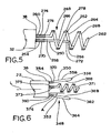
- the first tip 350 and the second tip 352 are both in the form of linear pins 366 and 368, respectively.
- the linear pins 366 and 368 are oriented at an angle A relative to the axis L of the lead body 22.
- the angle A measures in the range of five (5) degrees to sixty (60) degrees, with an angle of thirty-five (35) degrees being most preferable.
- the tip structure 348 also includes an anchor helix 371.
- the tip 350 includes an insulated portion 370 adjacent the proximal end 354, with the balance of the tip 350 being uninsulated.
- the tip 352 includes an insulated portion 374 adjacent the proximal end 360, with the balance of the tip 352 being uninsulated.
- the device may be used to pace the atrium when delivering anti-tachycardia pacing to diagnose the mechanism of the arrhythmia and to treat the arrhythmia. For example, one may employ the following exemplary steps: 1) pace the atrium, via the ring electrode C; 2) if arrhythmia terminates, then do nothing more; 3) if the arrhythmia does not terminate, then compare the atrial rate to the ventricular rate; 4) if the atrial rate is greater than the ventricular rate, then do nothing; and 5) if the ventricular rate is more than the (paced) atrial rate, then shock the heart/ventricle with the ICD.
- This approach may allow for potentially treating supraventricular arrhythmias and disassociating the atrium from the ventricle so as to allow for a more accurate diagnosis of the tachycardia mechanism.
- Figure 42 shows a lead tip having a plurality of intramyocardial electrodes disposed on a helix, and also having an additional ring electrode disposed on the lead body, with the additional ring electrode being non-intramyocardial and suitable for use in pacing, for example, the atrium.
Landscapes
- Health & Medical Sciences (AREA)
- Cardiology (AREA)
- Heart & Thoracic Surgery (AREA)
- Nuclear Medicine, Radiotherapy & Molecular Imaging (AREA)
- Engineering & Computer Science (AREA)
- Biomedical Technology (AREA)
- Vascular Medicine (AREA)
- Radiology & Medical Imaging (AREA)
- Life Sciences & Earth Sciences (AREA)
- Animal Behavior & Ethology (AREA)
- General Health & Medical Sciences (AREA)
- Public Health (AREA)
- Veterinary Medicine (AREA)
- Electrotherapy Devices (AREA)
Description
- The present invention relates generally to implantable leads for cardiac devices having pacing, sensing, and/or defibrillator leads and, more specifically, to improved tips for such leads.
- In the field of implantable cardiac devices implantable cardiac devices, implantable systems typically employ various leads for sensing and pacing cardiac activity, and for delivering electrical impulses for defibrillation. As is known, the leads are electrical conductors, typically covered with suitable coatings, and are placed at a desired location within the heart in order to deliver electrical impulses or sense of electrical activity at the appropriate location. The leads may be arranged linearly or coaxially, and are typically delivered using a variety of known delivery sheaths or catheters.
- Documenent
US 2008/294229 discloses an electrical lead for a cardiac device that includes a lead body and first and second electrodes having respective tips. Said document generally discloses various installation combinations for the first and second electrodes. - The present invention provides an electrical lead for a cardiac device as detailed in independent claims 1 and 11. Further embodiments of the invention are realised according to the corresponding dependent claims.
- In one example not falling within the scope of the claims, an electrical lead for a cardiac device includes a lead body having a proximal end and a distal end and sized for insertion through a lumen of a steerable catheter. First and second electrodes are provided having opposite polarity and extend through the lead body, with the first and second electrodes each terminating in a tip having a proximal end, a distal end, and an effective length, and with the tip of the first and second electrodes arranged to extend from the lead body for insertion into an area of cardiac tissue. The tip of the first electrode includes a fully insulated portion on the proximal end and a fully insulated portion on the distal end, with each of the fully insulated portions measuring in a range between 5 percent and 40 percent of an effective length of the tip of the first electrode. The tip of the first electrode further includes an intermediate section having an uninsulated portion. The tip of the second electrode includes a helical section surrounding a portion of the tip of the first electrode, the helical section having an outwardly facing portion facing away from the first electrode and an insulated inwardly facing portion facing toward the first electrode. The tip of the second electrode includes a fully insulated portion on the proximal end and a partially insulated portion extending from the fully insulated portion toward the distal end, with the fully insulated portion on the proximal end measuring in a range between 5 percent and 40 percent of an effective length of the tip of the second electrode.
- In a further example not falling within the scope of the claims, the tip of the first electrode may be linear, and the helical portion of the second electrode surrounds a portion of the first electrode. The effective length of the tip of the first electrode is less than the effective length of the tip of the second electrode, and may be about 75 percent of the effective length of the tip of the second electrode. The intermediate section of the tip of the first electrode may include insulation, and a partially uninsulated portion of the intermediate section may be formed by a plurality of perforations through the insulation. The helical portion of the tip of the second electrode may form or otherwise serve as an anchor arranged to secure the distal end of the lead body adjacent the area of cardiac tissue. The partially insulated portion of the helix includes no insulation on the outwardly facing surface. Each of the fully insulated portions of the tip of the first electrode measures from 5 percent to no more than 15 percent. Still preferably, one or more of the preferred forms disclosed herein mat permit placement of two electrodes of opposite polarity within the myocardium via a single lead, thus permitting intramyocardial stimulation with the absence of an electrode, such as a ring electrode, within a cardiac chamber
- In another example not falling within the scope of the claims, an electrical lead for a cardiac device includes a lead body having a proximal end and a distal end, with the lead body sized for insertion through a lumen of a steerable catheter. An anchor is arranged to secure the distal end of the lead body into cardiac tissue, and a first electrode and a second electrode are provided having opposite polarity and extend through the lead body. The first and second electrodes each terminate in a tip having a proximal end, a distal end, and an effective length, with the tip of the first and second electrodes arranged to extend from the lead body for insertion into the area of cardiac tissue. The tip of each of the first and second electrodes includes a fully insulated portion on the proximal end, a fully insulated portion on the distal end, with each of the fully insulated portions on both the proximal and distal ends having an insulated length measuring between 5 percent and 40 percent of an effective length of the tip. The tip of each of the first and second electrodes further includes an intermediate section between the proximal and distal ends having an uninsulated portion.
- In still a further example not falling within the scope of the claims, the tip of the second electrode may include a helical section surrounding a portion of the tip of the first electrode, with the tip of the second electrode including a fully insulated portion on the proximal end and an uninsulated portion extending from the fully insulated portion toward the distal end, and with the fully insulated portion on the proximal end measuring in a range between 5 percent and 40 percent of an effective length of the tip of the second electrode. Alternatively, the tip of the first electrode may include a fully insulated linear proximal end and an uninsulated helical distal end, and the tip of the second electrode may have a helical shape and include a fully insulated portion measuring in a range between 5 percent and 40 percent of an effective length of the tip of the second electrode. A portion of the tip of the second electrode may surround the linear proximal end of the tip of the first electrode. The first tip may be formed of a wire suture housed within a hollow lumen of a retractable central delivery pin, and the first tip may be sized to extend into the area of cardiac tissue upon retraction of the delivery pin. As another alternative, an anchor may secure a tip assembly adjacent to the area of cardiac tissue, and each the first tip and the second tip may include a plurality of outwardly extending bristles disposed adjacent the insulated distal end. The tip alternatively may include a pin arranged to extend from the lead body in a position adjacent the area of cardiac tissue, and may carry a first expandable electrode in electrical communication with the first electrode and a second expandable electrode in electrical communication with the second electrode, with each of the first and second expandable electrodes capable of being delivered through the lead body in a collapsed state and deployable into cardiac tissue, at or adjacent the desired area of cardiac tissue. Such electrodes may be formed of a memory material. Finally, an insulated tip may carry the first and second electrodes and may comprise a wire suture, with the first and second electrodes spaced apart on the tip. The tip and the first and second electrodes are sized to extend through a lead body having a proximal end and a distal end and sized for insertion through a lumen of a steerable catheter to allow placement of the first tip and the second tip adjacent an area of cardiac tissue.
- In accordance with a further example not falling within the scope of the claims, an electrical lead assembly for use with a cardiac device includes an insulated helix structure, the helix structure arranged to be embedded into an area of cardiac tissue, and a first electrode and a second electrode operatively carried by the helix structure, with the first and second electrodes spaced apart from one another along the helix structure and electrically insulated from one another. The helix structure and the first and second electrodes are sized to extend through a lead body having a proximal end and a distal end, with the lead body sized for insertion through a lumen of a steerable catheter to allow placement of the first tip and the second tip adjacent the area of cardiac tissue. The first electrode is operatively coupled to a first wire extending through an interior portion of the helix structure, with the first electrode comprising a first externally mounted conductive portion disposed about a first exterior portion of the helix. The second electrode is operatively coupled to a second wire extending through the interior portion of the helix structure, with the second electrode comprising a second externally mounted conductive portion disposed about a second exterior portion of the helix.
- In accordance with yet a further example not falling within the scope of the claims, an electrical lead assembly for use with a cardiac device includes a conductive helix structure, the helix structure arranged to be embedded into an area of cardiac tissue, the helix structure having an insulated portion and an uninsulated portion, a first electrode formed by the uninsulated portion of the helix structure, a second electrode operatively carried by the insulated portion of the helix structure, and with the first and second electrodes spaced apart from one another along the helix structure and electrically insulated from one another. The helix structure and the first and second electrodes are sized to extend through a lead body having a proximal end and a distal end, the lead body sized for insertion through a lumen of a steerable catheter to allow placement of the first tip and the second tip adjacent the area of cardiac tissue. Insulation preferably ensures that the first wire does not contact the helix, and the electrode mounted on the helix is electrically insulated from the helix, although mechanically the electrode may be embedded so as to form a single mechanical helix. The second electrode is operatively coupled to a wire extending through an interior portion of the helix structure, the second electrode comprising an externally mounted conductive portion disposed about a first exterior portion of the helix.
- In accordance with an additional example not falling within the scope of the claims, an electrical lead assembly for use with a cardiac device includes a helix, at least a portion of the helix arranged to be embedded into an area of cardiac tissue and with the helix having an insulated portion and a non-insulated tip, the non-insulated tip forming a first electrode. A coil covers at least a portion of the insulated portion of the helix, with the coil including an insulated portion and a non-insulated portion, the non-insulated portion extending distally past the insulated portion of the coil, with the non-insulated portion forming a second electrode. The first electrode and the second electrode spaced apart from one another by an exposed section of the insulated portion of the helix, and the helix and the first and second electrodes are sized to extend through a lead body having a proximal end and a distal end, the lead body sized for insertion through a lumen of a steerable catheter to allow placement of the first and second electrodes into the area of cardiac tissue. The first electrode is operatively coupled to a first wire extending through the lead body and arranged for operative coupling with the cardiac device, and the second electrode is operatively coupled to a second wire extending through the lead body and arranged for operative coupling with the cardiac device.
- In accordance with still a further example not falling within the scope of the claims, an electrical lead for a cardiac device includes a lead body having a proximal end and a distal end, the lead body sized for insertion through a lumen of a steerable catheter, a helix operatively coupled to the lead body adjacent the distal end, at least a portion of the helix arranged to anchor the lead body to an area of cardiac tissue, with the helix having a proximal insulated portion and a non-insulated portion adjacent a distal tip, the non-insulated portion forming a first electrode. A coil covers at least a portion of the insulated portion of the helix, with the coil having a proximal insulated portion and a non-insulated exposed portion, the non-insulated exposed portion extending distally past the proximal insulated portion of the coil, the non-insulated exposed portion forming a second electrode. The first electrode and the second electrode are spaced apart from one another by an exposed section of the insulated portion of the helix, and the helix and the first and second electrodes are sized to extend from the distal end of the lead body. The first electrode is operatively coupled to a first wire extending through the lead body and arranged for operative coupling with the cardiac device, and the second electrode is operatively coupled to a second wire extending through the lead body and arranged for operative coupling with the cardiac device. The first and second wires are insulated from one another throughout a length of the lead body.
-
-
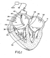
Figure 1 is a cross-sectional diagram of a heart illustrating the deployment of a bipolar pacing, sensing, or defibrillating lead via a lead body to the atrial ventricular septum. -
Figure 2 is an enlarged fragmentary view of a bipolar pacing lead assembled in accordance with the teachings of the present invention and illustrating an exemplary lead body terminating in lead tips for insertion in the myocardium at, for example, the atrial ventricular septum or at other suitable locations, with each of the lead tips electrically coupled to a corresponding electrode. -
Figure 3 is an enlarged fragmentary view of the distal end of the lead body showing a lead tip assembled in accordance with the teachings of a first disclosed example of the present invention. -
Figure 3A is a cross-sectional view taken along line 3A-3A ofFigure 3 , and illustrates a partially insulated helix having insulation on the portion of the helix that faces the centrally located tip or pin. -
Figure 4 is an enlarged fragmentary view of the distal end of a lead body and showing a lead tip. -
Figure 5 is an enlarged fragmentary view of the distal end of a lead body and showing a lead tip. -
Figure 6 is an enlarged fragmentary view of the distal end of a lead body and showing a lead tip. -
Figure 7 is an enlarged fragmentary view of the distal end of a lead body and showing a lead tip. -
Figure 8 is an enlarged fragmentary view of the distal end of a lead body and showing a lead tip. -
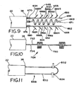
Figure 9 is an enlarged fragmentary view of the distal end of a lead body and showing a lead tip. -
Figure 10 is an enlarged fragmentary view of the distal end of a lead body and showing a lead tip. -
Figure 11 is an enlarged fragmentary view of the distal end of a lead body and showing a lead tip. -
Figure 12 is a diagrammatic view of a heart illustrating a lead delivery tool having a branch for registration with an anatomical landmark, such as the coronary sinus, having a known positional relationship relative to the atrioventricular septum to permit placement of a pacing, sensing, or defibrillator lead at the atrioventricular septum. -
Figure 13 is an enlarged diagrammatic view of the lead delivery tool illustrated inFigure 12 and showing a first lumen branch for registration with the anatomical landmark, and a second lumen branch for registration with the atrioventricular septum to permit placement of the electrode lead body at the atrioventricular septum. -
Figure 14 is a cross-sectional illustration of a heart and illustrating a delivery sheath having an undeployed blocking device equipped with a pair of sensors arranged for positioning on opposite sides of the tricuspid valve, wherein the blocking device may assist placement of a separate lead body at the atrioventricular septum. -
Figure 15 is a cross-sectional view similar toFigure 14 and illustrating the blocking device in a deployed state. -
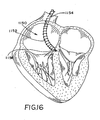
Figure 16 is another cross-sectional view of a heart and illustrating an implantable cardiac defibrillator (ICD) coil carried on an enlarged delivery sheath which has been routed over a pre-existing lead body for a pacing or sensing device. -
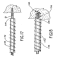
Figure 17 is an enlarged fragmentary view of the enlarged delivery sheath disposed adjacent a distal end of the existing lead body but shown in an unanchored state. -
Figure 18 is an enlarged fragmentary view similar toFigure 17 but showing the delivery sheath for the ICD coil in an anchored state secured to an area of cardiac tissue, such as the AVS. -
Figure 19 is a schematic view of a lead tip comprising an insulated inner helix surrounded by an insulated outer helix. -
Figure 20 is an enlarged fragmentary view, partly in section, of the double helix construction ofFigure 19 and illustrating a first set of holes or apertures in the insulation surrounding the outer helix, as well as a second set of holes or apertures through the outer helix and extending through the insulation and all the way to the inner helix. -
Figure 21 is an enlarged fragmentary view, partly in section, of another aspect of a double helix lead tip in which an insulated connector plug extends from the inner helix through an aperture in the insulated outer helix. -
Figures 22 and 23 are enlarged views of a lead tip comprising a jaw having a pair of opposed barbed prongs that are insulated from one another and that may be crimped inwardly toward one another to secure the barbed prongs to cardiac tissue. -
Figure 24 is a fragmentary elevational view of a lead tip comprising a spliced helix. -
Figure 25 is an enlarged cross-sectional view of the spliced helix ofFigure 24 . - Figures 26a, 26b and 26c are elevational views of a braided helix lead tip
-
Figure 27 is an enlarged cross-sectional view of the braided helix lead tip of figures 26a-c and illustrating portions of the exterior insulation removed to expose areas of opposite polarity. -
Figure 28 is an enlarged fragmentary view illustrating the distal end of a delivery sheath for delivering a two-wire lead tip and having an internal ramp to direct the distal ends of the wires. -
Figure 29 is an elevational view of a lead tip and having a nonconductive helix structure carrying a pair of electrodes in the form of coils attached to, formed on, or otherwise secured or adhered to the nonconductive helix. -
Figure 30 is an enlarged fragmentary view of the nonconductive helix lead tip ofFigure 29 in which insulated wires run through the helix to corresponding externally mounted cuffs. -
Figure 31 is an enlarged fragmentary view of the nonconductive helix lead tip ofFigure 29 in which insulated wires run through the helix to corresponding externally mounted coils formed from of a series of wire loops wound around the nonconductive helix. -
Figure 32 is an enlarged fragmentary cross sectional view illustrating one exemplary form of routing a wire through the helix ofFigure 29 and routing the wire through the helix such that the wire can be wound around the helix to form an external conductor such as a cuff or coil. -
Figure 33 is an enlarged fragmentary cross-sectional view illustrating another exemplary manner by which a wire may be routed through the helix and wound about the exterior of the helix to form an external cuff or coil in an area of reduced external diameter on the underlying helix. -
Figure 34 is an enlarged fragmentary cross-sectional view illustrating a pair of insulated wires running through the center lumen of the helix. -
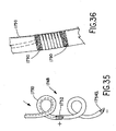
Figure 35 is an elevational view of a lead tip having an insulated and conductive helix structure carrying an external cuff or coil to form one electrode and having an area of removed insulation, in this case at the distal end of the lead tip, to form another electrode having opposite polarity. -
Figure 36 is an enlarged fragmentary elevational view illustrating the externally formed cuff or coil bounded by a polymer, adhesive, or other bonding agent in order to seal any holes or apertures through the underlying helix and two minimize movement were sliding of the external cuff or coil. -
Figures 37a, 37b, 37c and 37d are elevational views of further exemplary lead tips, which may be the same or similar to any one of the lead tips shown inFigure 19 ,Figure 24 , and/orFigures 29-36 , with the lead tips provided with multiple electrodes in a symmetrical arrangement as shown inFigure 37a , an asymmetric arrangement as shown inFigure 37b and 37c , or with the electrodes spaced in near-field and far-field pairs as shown inFigure 37d . -
Figure 38 is a graphical depiction of cardiac activity and illustrating the relationship between R wave amplitude and T wave amplitude. -
Figure 39 is an enlarged fragmentary schematic view in section illustrating a lead tip having a plurality of electrodes or electrode pairs disposed at various positions relative to the distal end of the deployment instrument and shown with various electrodes or electrode pairs disposed in different areas of the relevant cardiac tissue, such as the sub-endocardium, the mid-myocardium, and/or the sub-epicardium. -
Figure 40 is an enlarged fragmentary view of an exemplary delivery sheath and corresponding helical lead tip protruding from the delivery sheath, in which the delivery sheath or other delivery instrument includes a primary winding while the helical lead tip includes a secondary winding to enable the voltage at the lead tip to be stepped up according to known electrical principles. -
Figure 41 is an enlarged fragmentary view in section of a retractable drive mechanism for embedding any one of the foregoing helical or helix-shaped lead tips into desired tissue, and having a retractable stylet/driver which is releasably engageable with the lead tip and which is arranged to rotationally drive the lead tip according to a known mechanical ratio, such as a 1:1 drive ratio. -
Figure 42 is an enlarged fragmentary view illustrating an exemplary lead tip having a plurality of intramyocardial electrodes disposed on a helix, and also having an additional ring electrode disposed on the lead body, with the additional ring electrode being non-intramyocardial and suitable for use in pacing, for example, the atrium. -
Figure 43 is an enlarged fragmentary view in perspective of the distal end of the lead body and showing a lead tip shown in an anchored state secured to an area of cardiac tissue, such as the AVS. -
Figure 44 is a further enlarged fragmentary view in perspective of the lead tip shown inFigure 43 . -
Figure 45 is an enlarged elevational view of an exemplary helix for use in the lead tip ofFigures 43 and44 . -
Figure 46 is left side elevational view of the helix ofFigure 45 . -
Figure 47 is an enlarged fragmentary elevational view of a portion of the helix ofFigures 43 and44 having an exemplary braided coil arrangement surrounding the portion of the helix. -
Figure 47A is a cross-sectional view of the braided coil ofFigure 47 . -
Figure 48 is an enlarged fragmentary elevational view of a portion of the helix ofFigures 43 and44 having an exemplary three-wire coil arrangement surrounding the portion of the helix. -
Figure 48A is a cross-sectional view of the three-wire arrangement ofFigure 48 . -
Figure 49 is an enlarged fragmentary elevational view of a portion of the helix ofFigures 43 and44 having an exemplary wire mesh coil arrangement surrounding the portion of the helix. - Referring now to the drawings,
Figures 1 illustrates an exemplarylead deployment system 20 for deploying an electrical lead 21 (obscured inFigure 1 but shown inFigure 2 ) having alead body 22 to cardiac tissue located at a desiredarea 24 on the atrioventricular septum (AVS) 26 within a heart H. The heart H includes aright atrium 28, aleft atrium 30, an area of themyocardium 32, and atricuspid valve 34. Thelead body 22 includes aproximal end 36 illustrated schematically inFigure 1 , and adistal end 38. Theproximal end 36 is shown connected to an implantable cardiac device or ICD. Thelead body 22 typically includes alumen 40, which typically houses at least two conductors (describing greater detail below with respect to, for example,Figure 2 ) which run through thelumen 40, generally along anaxis 42 of thelumen 40. Thelumen 40 is typically part of a steerable catheter of the type commonly employed in the relevant art. A more complete description of the exemplarylead deployment system 20 can be found in co-pendingU.S. Provisional Patent Application No. 60/753,098, filed December 25, 2005 U.S. Non-provisional Patent Application No. 12/131,756, filed June 2, 2008 - Referring now to
Figure 2 , thedistal end 38 of thelead body 22 is shown in greater detail. Anelectrode 44 and anelectrode 46 are shown within thelumen 40 of thelead body 22. The shape, arrangement, and/or the orientation for theelectrodes electrodes electrodes tip structure 48, with at least portions of thetip structure 48 being structured for insertion or implantation into the desiredarea 24 of cardiac tissue as will be discussed in greater detail below. Those of skill in the art will also understand that theelectrode - Referring now to
Figure 3 , thetip structure 48 is shown in greater detail and is assembled in accordance with the teachings of a first disclosed example of the present invention. Thetip structure 48 is shown attached to thedistal end 38 of thelead body 22, with afirst tip 50 and asecond tip 52 protruding from the distal and 38 of thelead body 22. Thefirst tip 50 preferably is electrically coupled to theelectrode 44, while thesecond tip 52 is electrically coupled to theelectrode 46. Thefirst tip 50 includes aproximal end 54, adistal end 56 and anintermediate portion 58. Thesecond tip 52 also includes aproximal end 60, adistal end 62, and anintermediate portion 64. In the embodiment ofFigure 3 , thefirst tip 50 is in the form of alinear pin 66, while thesecond tip 52 is in the form of ahelix 68, with thelinear pin 66 having an effective length L1 and with thehelix 68 having an effective length L2. According to the exemplary form ofFigure 3 , the effective length L2 is greater than the effective length L1. In one preferred form, effective length L1 is approximately 75% of the effective length L2. The effective length may be the overall length of the helix, rather than the length measured along the circuitous path of the curving helix. The effective length may be measured in the undeployed state, because it could be hard to measure the effective length when actually implanted. Those of skill in the art will understand that thetips distal end 38 of thelead body 22 such that thetips area 24 of cardiac tissue. - Referring still to
Figure 3 , thetip 50 includes an insulatedportion 70 adjacent theproximal end 54 and aninsulated portion 72 adjacent thedistal end 56. In the example ofFigure 3 , theinsulated portions intermediate portion 58 is uninsulated. As an alternative, theintermediate portion 58 may be partially insulated, and the partially insulated portion may include an insulated layer having a plurality ofperforations 59 through the insulation. Preferably, the exposed area of a pin or pins may lie in the range of 10% to 90% of the pin area. Preferably, each of theinsulated portions first tip 50. Still preferably, each of theinsulated portions helix 68 of thesecond tip 52 winds around thefirst tip 50 so as to surround a portion of thefirst tip 50, and thesecond tip 52 includes an insulatedportion 74 adjacent theproximal end 60. In the example ofFigure 3 , theinsulated portion 74 is fully insulated, and measures in a range between 5% and 40% of the effective length L-2 of thesecond tip 52. Theinsulated portion 74 includes anend 76, at which point the insulation transitions to a partially insulatedportion 78. - Referring now to
Figure 3A , a portion of thehelix 68 and a portion of thelinear pin 66 are shown. Thehelix 68 includes an upwardly facingsurface 80 facing away from thelinear pin 66 of thefirst tip 50, and further includes an inwardly facingsurface 82 facing toward thelinear pin 66 of thefirst tip 50. The partially insulatedportion 78 is formed by a layer ofinsulation 84 formed or otherwise suitably applied to the inwardly facingsurface 82 of thehelix 68. In accordance with the disclosed example, the current between the first andsecond tips tip pin 66 and thehelix 68. Such an arrangement may allow electrical impulses to capture a greater area of tissue. - In the example of
Figure 3 and3A , the insulation forming the insulated portions may be any material that can prevent or minimize the conduction of electricity. The insulation of the proximal and/or distal ends of the tips may minimize or prevent short-circuiting in the event thehelix 68 and thepin 66 come in contact with one another. Further, in accordance with the disclosed example, the insulation at the proximal ends of both thelinear pin 66 and thehelix 68 may minimize or prevent certain problems such as, for example, far field sensing and/or abberant tissue stimulation in the event that thetips area 24 of the myocardium at the AVS during implantation. Further, it will be understood that thetips 50 and 52 (i.e., thelinear pin 66 and the helix 68) are both retractable and/or deployable such that during delivery the distal ends 56 and 62 do not protrude from thedistal end 38 of thelead body 22. Once thehelix 68 is in place, thelinear pin 66 may be deployed out of thelead body 22 into the myocardium. - Referring now to
Figure 4 , another embodiment of a tip structure 148 is shown. The tip structure 148 again is attached to thedistal end 38 of thelead body 22 with a first tip 150 and asecond tip 152 protruding from thedistal end 38 of thelead body 22. Once again, the first tip 150 and thesecond tip 152 are electrically coupled to corresponding electrodes (not shown) in a manner similar to that discussed above with respect to the first disclosed example. The first tip 150 includes aproximal end 154, adistal end 156, and an intermediate portion 158. Thesecond tip 152 also includes a proximal end 160, adistal end 162, and anintermediate portion 164. In the embodiment ofFigure 4 , the first tip 150 and thesecond tip 152 are both in the form oflinear pins linear pins anchor 169 which, in the example ofFigure 4 , is in the form of ahelix 171. The tip 150 includes aninsulated portion 170 adjacent theproximal end 154, it and aninsulated portion 172 adjacent thedistal end 156. Similarly, thetip 152 includes aninsulated portion 174 adjacent the proximal end 160 and aninsulated portion 175 adjacent thedistal end 162. In the example ofFigure 4 , the insulated portions on each of thetips 150 and 152 has a length measuring the inner range between 5% and 40% of the length of thetips 150 and 152. Preferably, the length of theinsulated portions anchor 169 is preferably insulated along its entire length. Theintermediate portions 158 and 164 of thetips 150 and 152, respectively, are preferably uninsulated or only partially insulated. In the example ofFigure 4 , thepins pins 166 168 can be variable, with the preferred length being about 75% of the effective length of the anchor/helix. Preferably, the effective lengths are measured in the same manner as that discussed above with respect to the first disclosed example. - Referring now to
Figure 5 , atip structure 248 is shown. Thetip structure 248 is shown attached to thedistal end 38 of thelead body 22, with afirst tip 250 and asecond tip 252 protruding from thedistal end 38 of thelead body 22. Thetips first tip 250 includes aproximal end 254, adistal end 256 and anintermediate portion 258. Thesecond tip 252 also includes aproximal end 260, adistal end 262, and anintermediate portion 264. In the embodiment ofFigure 3 , thefirst tip 250 is in the form of alinear pin 266, while thesecond tip 252 is in the form of ahelix 268, with thelinear pin 266 having an effective length L1 and with thehelix 268 having an effective length L2 (again measured as discussed above). According to the exemplary form ofFigure 4 , the effective length L2 is greater than the effective length L1 and, in one preferred form, is approximately 75% of the effective length L2. Thetip 250 includes aninsulated portion 270 adjacent theproximal end 254 and aninsulated portion 272 adjacent thedistal end 256. Theinsulated portions intermediate portion 258 is uninsulated. Preferably, each of theinsulated portions first tip 250. Still preferably, each of theinsulated portions helix 268 of thesecond tip 252 winds around thefirst tip 250 so as to surround a portion of thefirst tip 250. Thesecond tip 252 includes aninsulated portion 274 adjacent theproximal end 260. Theinsulated portion 274 is fully insulated, and measures in a range between 5% and 40% of the effective length L2 of thesecond tip 252. Theinsulated portion 274 includes anend 276, at which point the insulation transitions to anuninsulated portion 278. - Referring now to
Figure 6 , another embodiment of atip structure 348 is shown. Thetip structure 348 is similar in some respects to the tip structure 148 discussed above with respect toFigure 4 . In the interest of brevity, only the significant differences between the embodiment ofFigure 6 and the embodiment ofFigure 4 will be discussed in detail, it being understood that all remaining features may be the same or similar with the features discussed above. Afirst tip 350 and asecond tip 352 protrude from thedistal end 38 of thelead body 22, with thefirst tip 350 having aproximal end 354, adistal end 356, and anintermediate portion 358, and with thesecond tip 352 having aproximal end 360, adistal end 362, and anintermediate portion 364. In the embodiment ofFigure 6 , thefirst tip 350 and thesecond tip 352 are both in the form oflinear pins linear pins lead body 22. Preferably, the angle A measures in the range of five (5) degrees to sixty (60) degrees, with an angle of thirty-five (35) degrees being most preferable. Thetip structure 348 also includes ananchor helix 371. Thetip 350 includes aninsulated portion 370 adjacent theproximal end 354, with the balance of thetip 350 being uninsulated. Similarly, thetip 352 includes aninsulated portion 374 adjacent theproximal end 360, with the balance of thetip 352 being uninsulated. The insulated portions on each of thetips tips anchor helix 371 may have an insulatedportion 373 adjacent aproximal end 375 with the balance being either fully insulated, uninsulated, or partially insulated. Preferably, the lengths of thepins anchor helix 371. - Referring now to
Figure 7 , atip structure 448 is shown. Thetip structure 448 again is shown attached to thedistal end 38 of thelead body 22 in a manner substantially similar to those embodiments described above. Afirst tip 450 includes aproximal end 454, adistal end 456, anintermediate portion 458, while thesecond tip 452 includes aproximal end 460, adistal end 462, and anintermediate portion 464. In the embodiment ofFigure 7 , thefirst tip 450 is in the form of a linear portion 466 from the proximal end of 454 to a boundary ortransition 459 adjacent a central part of theintermediate portion 458. After thetransition 459, thefirst tip 450 includes ahelical portion 461 extending to thedistal end 456. Thesecond tip 452 is in the form of ahelix 468. According to the exemplary form ofFigure 7 , a combined length L2 of thehelical portion 461 and the linear portion 466 is greater than the effective length L2 of thehelix 468. Preferably, all of the linear portion 466 of thefirst tip 450 is insulated, while thehelical portion 461 extending from thetransition 459 is uninsulated. Thesecond tip 452 preferably includes aninsulated portion 472 that measures in a range between 5% and 40% of the effective length L2 of thehelix 468. Still preferably, theinsulated portion 472 measures about 15% of the effective length L2 of thehelix 468. - Referring now to
Figure 8 , atip structure 548 is shown. Thetip structure 548 is similar in many respects to the embodiment ofFigure 5 . Therefore, in the interest of brevity, to the extent practical only the significant differences between the embodiment ofFigure 8 and the embodiment ofFigure 5 will be discussed in detail. Afirst tip 550 includes aproximal end 554, adistal end 556 and anintermediate portion 558, while asecond tip 552 includes aproximal end 560, adistal end 562, and anintermediate portion 564. In the embodiment ofFigure 8 , thefirst tip 550 is in the form of awire suture 566, while thesecond tip 552 is in the form of ahelix 568. Thewire suture 566 preferably is made from a relatively fine gauge wire, and thus may be more flexible relative to the larger gauge, stiffer linear pins employee in other embodiments discussed herein. During deployment, thehelix 568 of thesecond tip 552 is placed into the targetedarea 24 of cardiac tissue (preferably AVS or other suitable areas of the myocardium). Then alumen 569 of acentral delivery pin 571 is advanced into the selected area of cardiac tissue, with thedelivery pin 571 in turn located within the lumen of the delivery catheter. Thedelivery pin 571 is then retracted, leaving the wiresuture wire suture 566 in place. Preferably, theproximal end 560 of thetip 552 includes an insulateportion 574. Still preferably, theinsulated portion 574 measures a range between 5% and 40% of the effective length L1 of thefirst tip 550, and more preferably about 15% of the effective length L1. - Referring now to
Figure 9 , another embodiment of atip structure 648 is shown. Thetip structure 648 again is attached to thedistal end 38 of thelead body 22 with afirst tip 650 and asecond tip 652 protruding from thedistal end 38 of thelead body 22. Once again, thefirst tip 650 and thesecond tip 652 are electrically coupled to corresponding electrodes (not shown) in a manner similar to that discussed above with respect to the above-described examples. Thefirst tip 650 includes aproximal end 654, adistal end 656, and anintermediate portion 658. Thesecond tip 652 also includes aproximal end 660, adistal end 662, and anintermediate portion 664. In the embodiment ofFigure 9 , thefirst tip 650 and thesecond tip 652 are both in the form oflinear pins linear pins linear pins tip structure 648 also includes ananchor 669 which, in the example ofFigure 9 , is in the form of ahelix 671. Preferably the bristles 666a-e and 668a-e are arranged to deploy away from thehelix 671, although thehelix 671 may be insulated. Thetip 650 includes aninsulated portion 670 adjacent theproximal end 654, while thetip 652 includes an insulated portion 674 adjacent theproximal end 660. The insulated portions on each of thetips tips anchor 669 is preferably insulated along its entire length. Theintermediate portions tips Figure 9 , thepins lead body 22 and into the myocardium, preferably at no angle or at only a small angle. Preferably, the length of thepins separate anchor 669 may be eliminated. - Referring now to
Figure 10 , yet a further embodiment of atip structure 748 is shown. Thetip structure 748 again is attached to thedistal end 38 of thelead body 22. Acentral portion 750 carries afirst electrode 752 and asecond electrode 754, which are insulated from one another and insulated for thecentral portion 750. Once again, theelectrodes electrodes lead body 22 so as to extend from thedistal end 38. - Referring now to
Figure 11 , a still further embodiment of atip structure 848 is shown. Thetip structure 848 again is attached to thedistal end 38 of thelead body 22. Thetip structure 848 includes aninsulated wire suture 850, and afirst electrode 852 and asecond electrode 854 are carried by and spaced along thewire suture 850, which are preferably insulated from one another. Once again, theelectrodes wire suture 850 may be a braided wire formed of multiple insulated wires, which enables theelectrodes wire suture 850 yet remain insulated from one another Preferably, the wire suture is flexible enough to be deployed through a needle into the myocardium or other targeted tissue. - Based on the embodiment disclosed in
Figure 11 , the device could be modified to deliver two separate sutures from the same apparatus and may be used for intramyocardial bipolar pacing. By tightening one suture more or less than the other suture, it may be possible to, in effect, have different size electrodes or conduction velocities downstream from one electrode. This arrangement may allow for pacing from more than one location using the same bipolar pair. Further, the wire suture may itself have more than one electrode. The wire suture structure may be used epicardially or endocardially to capture or lasso a piece of myocardium, thus not only working as an intramyocardial electrode, but also as a fixation mechanism. - Referring now to
Figures 12 and13 , alead delivery tool 950 is shown. Thelead delivery tool 950 includes adelivery sheath 952 having a curved design that is adapted to cannulate the coronary sinus ostium. Delivery sheaths designed to cannulate the coronary sinus are known and readily available. Thelead delivery tool 950 includes afirst lumen 954 having adistal end 956 which carries anexpandable component 958, which may be a compliant balloon or a nitinol component. Thedelivery sheath 952 is routed to the opening of the coronary sinus CS, and theexpandable component 958 is expanded or inflated to secure the sheath at the coronary sinus. Thedelivery tool 950 includes asecond lumen 960, which branches off thedelivery tool 950. Thesecond lumen 960 is sized and located relative to thefirst lumen 954 such that, when thefirst lumen 954 is disposed at the coronary sinus, thesecond lumen 960 will be located adjacent the AVS. Consequently, thesecond lumen 960 provides a platform to deliver thelead body 22 to the AVS, whereby any one of the above-described examples of the foregoing lead body and tip structures may be routed to the AVS. In further accordance with a preferred form of the invention, thesecond lumen 960 may include a telescoping pre-formed inner sheath that would accommodate the selected lead body and that would route the lead body closely adjacent the AVS. The first andsecond lumens delivery tool 950 based upon evidence that there is a relatively fixed relationship between the coronary sinus and the AVS. Further, there is evidence that since the coronary sinus and the AVS, at least from the perspective of the right atrial endocardial location, are in relative juxtaposition, they move together during cardiac motion. Accordingly, a sheath stabilized in the coronary sinus ostium may provide a stable platform for deploying an atrioventricular septal lead. The component of the main sheath in the coronary sinus could have a very tiny lumen, simply enough to allow placement of a wire for stability and confirmation of position or injection of contrast to confirm positioned within the coronary sinus. At best, most of the lumen could be made available for the fork or the side hole design for permitting placement of the lead at the AVS. Such a lead may be a "peel away" or "cuttable" lead to allow for lead deployment. Plus, the lead would not have to have a modified proximal end and could use standard IS-1 connectors, which are standard in all current pacemakers and defibrillator pace-sense ports. Finally, the example ofFigures 12 and13 may be usable for some patients in whom atrioventricular septal pacing may provide protection against tricuspid regurgitation by not violating the tricuspid valve, but may not effectively resynchronize congestive heart failure. These patients could require an AVS lead at a second lead at the left ventricle (via the coronary sinus). It is conceivable that in a subset of patients who may benefit from a lead placed at the AVS, a more traditional left ventricular lead may be placed through the sheath in the coronary sinus into a more traditional left ventricular position. This "forked sheath" would permit placement of both leads using a single sheath and facilitate the implant procedure. - Referring now to
Figures 14 and15 , anotherdelivery tool 1050 is shown. In the example ofFigures 14 and15 , thedelivery tool 1050 includes adelivery sheath 1052 having aproximal sensor 1054, adistal sensor 1056, and anexpandable component 1058 located on thedelivery sheath 1052 between theproximal sensor 1054 and thedistal sensor 1056. The proximal anddistal sensors delivery tool 1050 is positioned such that theproximal sensor 1054 is disposed in the right atrium while the distal sensor is disposed in the right ventricle. Consequently, the proximal sensor reports atrial pressures and electrograms, while the distal sensor reports distal pressures and electograms. Once a physician establishes the correct placement of thedelivery tool 1050, with each of the sensors in the appropriate chamber, theexpandable component 1058 may be deployed above the tricuspid valve. A lead body, which may be thelead body 22 discussed above with respect to the foregoing examples, can then be deployed out of thedelivery sheath 1052 or through a separate delivery sheath (not shown, but which may be the same or similar to any one of the delivery devices discussed herein). Theexpandable component 1058, which may be an expandable balloon, a memory material, or any other suitable expandable component, keeps thelead body 22 in the right atrium and prevents the physician from accidentally slipping below the tricuspid valve into the right ventricle. In addition to helping to obtain correct placement of thelead body 22 at or adjacent the AVS, this arrangement may minimize or prevent the risk that thelead body 22 slips below the tricuspid valve, thus minimizing or preventing possible damage to the tricuspid valve. - Referring now to
Figures 16-18 , anotherdelivery tool 1150 is shown. Thedelivery tool 1150 assembled in accordance with the teachings of the disclosed example allows for placement of an implantable cardiac defibrillator (ICD) to be deployed over an already placed lead 23 (Figure 17 ), which may be a pacing lead, a sensing lead, or any other existing lead. Thedelivery tool 1150 includes adelivery sheath 1152 having acentral lumen 1154 large enough to fit over thelead 23 during deployment, and includes a proximal end (not shown) and adistal end 1156. This "over the lead" (OTL) ICD arrangement is placed over the existinglead 23 and then is secured at thedistal end 1156. In the arrangement ofFigures 16-18 , the disclosed design may allow for a CRT-D unit to be created around theAVS pacing lead 23. Thus, the resulting CRT-D does not cross a cardiac valve. In the arrangement ofFigures 16-18 , thecoils 1150 may be fixed at the proximal end to the ICD, or may be fixed adjacent the distal end using a deployable anchor 1158 (Figure 18 ), which preferably is ahelical anchor 1160. Note that in this embodiment the helical anchor can also serve as an intramyocardial ICD coil, to allow for delivery of energy directly into the myocardium. This could allow for better defibrillation thresholds. The ICD coil placed over-the-lead could be placed entirely within the myocardium or with a portion of the coil within the myocardium and a portion outside the myocardium as shown inFigure 18 . - Exemplary algorithms may improve ICD performance based on the use of intramyocardial sensing leads. The following examples take advantage of the fact that all pacing and sensing leads may be located completely intramyocardially.
- For example, one exemplary algorithm may guide the timing of morphology templates as well as morphology comparison during tachycardia. One of the common modalities of failure of morphology algorithms, which compare the morphology of an electrogram during tachycardia to template morphology recorded during normal rhythm, is the difficulty in aligning the two templates. If there is slight deviation in the peak of the template (which is often used for alignment), or minor change in the onset of the electrogram during tachycardia as compared to baseline (despite being an exact match otherwise), then templates and tachycardia electrograms are said to be different by analysis despite actually being the same. Given the benefit of the intramyocardial fixed reference, alignment errors may be rare or non-existent, as the intramyocardial electrogram would serve as an excellent fiducial point. Thus, the tachycardia intramyocardial electrogram timing point would be used as the reference time and compared to the template intramyocardial electrogram timing point. The far field electrograms would actually then be compared aligned using the intramyocardial electrogram. This approach may minimize or eliminate "phase shift" errors in comparing electrogram morphology.
- Next, during tachycardia, it is possible to assess the response of tachycardia during basal/septal VPCs (premature ventricular contractions) placed within the septal myocardium. If placement of such VPCs as either single impulses or burst dissociates the ventricle from the atrium during a 1:1 tachycardia without change in the atrial rate, then an atrial tachycardia is diagnosed. Alternatively, if a burst of pacing from the site results in 1:1 ventriculoatrial conduction, then the pattern of resumption of activity following the pacing could define the arrhythmia mechanism. Thus, if upon discontinuation of pacing there is a VVA (ventricular beat, ventricular beat, atrial beat) pattern, then VT (ventricular tachycardia) is diagnosed and treated. However, if upon termination of pacing there is a VAV (ventricular beat, atrial beat, ventricular beta) or VAAV pattern, then supraventricular tachycardia is diagnosed and no painful/shock therapy is delivered. The fact that there may be available reliable ventricular and atrial sensing permits use of these forms of maneuvers that would be otherwise difficult for the device to interpret. In an alternative approach which could also be complementary, the atrium could be paced. If accelerating the atrium does not accelerate ventricular activation, this indicates VT.
- One possible primary differentiation/algorithms for SVT is atrial pacing instead of, or in addition to, ventricular pacing in a pre-programmed zone. For slower arrhythmias, atrial pacing may terminate an atrial flutter or transiently slow sinus tachycardia. In addition, if AV nodal conduction is good, then a VT may be terminated possibly easier than pacing the ventricle itself. If AV nodal conduction is poor, then dissociation or variable AV intervals will result, thus suggesting ventricular tachycardia. Simultaneous atrioventricular pacing could also be considered during charge. Thus, it may be desirable to incorporate such an algorithm into a device. In so doing, the device may be coupled to one or more of the lead structures disclosed herein, and the device could have another electrode, which may be the type found in standard leads that are not intramyocardial, and then use that additional lead to pace the atrium and use the intramyocardial lead to pace the ventricle. If such an arrangement is combined with the ICD, this would be useful as a single lead, not necessarily for atrial pacing, but specifically for this differentiating algorithm. See, for example,
Figure 42 , which shows an exemplary pair of electrodes A and B for placement in the myocardium, and the additional ring electrode C which may be a standard ring electrode and which is no placed into the myocardium. Those of skill in the art will understand that the electrodes A and B may be replaced with any of the other lead tip/electrode designs outlined herein. - In the approach of
Figure 42 , the device may be used to pace the atrium when delivering anti-tachycardia pacing to diagnose the mechanism of the arrhythmia and to treat the arrhythmia. For example, one may employ the following exemplary steps: 1) pace the atrium, via the ring electrode C; 2) if arrhythmia terminates, then do nothing more; 3) if the arrhythmia does not terminate, then compare the atrial rate to the ventricular rate; 4) if the atrial rate is greater than the ventricular rate, then do nothing; and 5) if the ventricular rate is more than the (paced) atrial rate, then shock the heart/ventricle with the ICD. This approach may allow for potentially treating supraventricular arrhythmias and disassociating the atrium from the ventricle so as to allow for a more accurate diagnosis of the tachycardia mechanism. - Next, if there were to be more than two electrodes within the myocardium, we could then make actual vector velocity and directionality determination of wave front propagation within the muscle either across the septum or from apex to base or base to apex depending on how the lead replaced. The positioning of multiple intramyocardial electrodes would allow actual measurement of conduction of velocity and directionality from one electrode to the next. Recording these patterns during a baseline normal rhythm and comparing them during a tachycardia would further permit differentiation of SVT (supraventricular tachycardia) from VT.
- Further, the differential response to high and low output pacing from the intraventricular septum tachycardia and normal rhythm may also permit differentiation between SVT and VT.
- Also, intratmyocardial electrodes could be a way of electrically causing transient AV (atrioventricular) nodal block, if high energy output or very low energy intramyocardial shock can reliably introduce block. Shock delivered in a right ventricular coil results in frequent right bundle branch block that may last a short period of time, for example a minute or two. If a reliable AV node block that is short lived can be developed, then this would be of beneficial in determining the mechanism of arrhythmia and could prove to terminate many supraventricular arrhythmias. Thus, this could be uniquely therapeutic and diagnostic.
- Finally, if an atrial electrogram recorded by an intramyocardial atrial lead is used, then it is possible to know reliably when p wave activity is occurring. Thus, it is possible to exclude the p wave by digitally subtracting it from far field electrograms to reliably analyze the electrograms for morphology (if there is 1:1 VA conduction during a tachycardia).
- In accordance with one or more of the above-described exemplary forms of the invention, better sensing of cardiac activity may be possible. In one or more exemplary forms, better sensing allows better performance of ICD's, and places less of a burden on adjusting control algorithms which, in prior systems, typically had to be adjusted to account for poor signal quality. Further, in accordance with one or more exemplary forms discussed above, the present invention may provide better sensing and better pacing of ICD's or other devices by placing both the pacing lead and the sensing lead into the myocardium.
- It has been discovered that, in some circumstances, it may be advantageous to restrict, limit, or otherwise contain the delivery of the IM electrodes to the myocardium within to a single moving delivery element. To facilitate the delivery of both electrode poles into the myocardium within a single moving platform or element, several exemplary additional embodiments have been developed for the lead tip assembly.
- Referring now to
Figures 19-21 , another exemplarylead tip structure 1248 is shown. Thelead tip structure 1248 takes the form of a "helix-within-a-helix." Thelead tip structure 1248 may be used in place of one or more of the lead tip structures discussed above. Thetip structure 1248 is in the form of ahelix 1249. As best as shown inFigure 20 , thehelix 1249 includes aninner helix 1251 and anouter helix 1253. Theinner helix 1249 extends through apassage 1255 formed by the hollowouter helix 1253. Theinner helix 1251 includesinsulation 1257, while theouter helix 1253 includesinsulation 1259. It will be appreciated that theinner helix 1251 is conductive, as is theouter helix 1253. The insulation applied about theinner helix 1251 prevents electrically conductive contact between theinner helix 1251 and theouter helix 1253. In the example shown, theouter helix 1253 is designated as a positive electrode while theinner helix 1251 is designated as the negative electrode. The polarity may be switched if desired. A gap orhole 1261 is formed through theinsulation 1259 on theouter helix 1253 to expose a portion of the conductiveouter helix 1253, thus forming anelectrode 1265. Alternatively, there may be a series or plurality of gaps or holes through theinsulation 1259 on theouter helix 1253 in order to expose additional portions of the conductiveouter helix 1253 to formadditional electrodes 1265. Another gap orhole 1263 is formed through the outer helix 1253 (through theinsulation 1259 and through the exterior or the wall of the outer helix 1253). The gap orhole 1263 extends through theinsulation 1257 on theinner helix 1251 in order to expose a conductive portion of theinner helix 1251, and consequently forms anelectrode 1267. Again, there may be a series or plurality of gaps or holes extending to theinner helix 1251 to formadditional electrodes 1267. - Preferably, both the
inner helix 1251 and theouter helix 1253 are fully insulated to prevent contact between the two helixes which would result in short-circuiting. Theinsulation 1259 on theouter helix 1253 may be etched away (via chemical, laser, or mechanical etching) at various points to create theelectrodes 1265. Separately, holes are created within the outer helix, and the insulation is etched away from the inner helix at the same point to create the opposite pole electrode. - Referring to
Figure 21 , theelectrode 1267 carried by theinner helix 1251 may take the form of an optional connector plug 1268 that extends from theinner helix 1251 through a suitable aperture or hole through the surface of theouter helix 1253. The connector plug 1268 may includeinsulation 1272. The connector plug 1268 will be in suitable electrical contact with the conductiveinner helix 1251. The insulation on the outside of the connector plug 1268 preferably spans thehole 1270 created in the outer helix and thereby prevents short-circuiting. Still preferably, the connector plug 1268 is shaped to correspond to the shape of thehole 1270 in theouter helix 1253. The connector plug 1268 could be fixed in place by a variety of methods (adhesive, welding, physical force, etc.). - Referring now to
Figures 22 and 23 , another exemplarylead tip structure 1348 is shown. Thelead tip structure 1348 takes the form of ajaw 1350, such as an inwardly crimpable jaw having afirst arm 1351 and asecond arm 1353. Thelead tip structure 1348 may be used in place of one or more of the lead tip structures discussed above. Eacharm lead tip structure 1348 contains or otherwise forms anelectrode electrodes barb jaw 1350 would be delivered to the tissue of interest, either in an open state or in a closed state. Preferably, thejaw 1350 then would be used to grasp the tissue to be stimulated and, in the process, drive theelectrodes arms arms jaw 1350. This embodiment may be particularly useful for moderator band pacing. The moderator band is a prominent muscle bundle which crosses from the septomarginal trabeculation to the anterior papillary muscle and then to the parietal wall of the right ventricle. - Referring now to
Figures 24 and 25 , another exemplarylead tip structure 1448 is shown. Thelead tip structure 1448 takes the form of a splicedhelix 1450 in which twoseparate wire halves helix 1450. Each half is in electrical communication with a corresponding electrode. Both halves preferably are fully insulated, including along an insulated interface 1454. Portions of the insulation are removed from each of thehalves electrodes - Referring now to
Figures 26 and 27 , another exemplarylead tip structure 1548 is shown, and which forms a "braided helix" embodiment. This approach consists of two conductingwires 1551 and 1553 which are first braided together and then formed into ahelix 1550. The distal tips 1551a and 1553a of the two wires can be embedded into aplastic tip 1555 to prevent short-circuiting and to prevent unwinding of the wires. The two wires can be fully insulated, with insulation etched away at conduction sites to form therelevant electrodes -
Figure 28 illustrates an exemplary "hook-wire" anchor ortip structure 1648. This approach again includes of twoindependent wires wire -
Figures 29-34 illustrate alead structure 1748. Thelead structure 1748 includes anonconductive helix 1750 having a first externally mountedelectrode 1752 and a second externally mountedelectrode 1754 spaced apart along thehelix 1750. As shown inFigure 30 , the externally mounted electrodes may take the form of aconductive cuff helix 1750. Thecuff 1755 is electrically connected to a firstconductive wire 1759 while thesecond cuff 1757 is electrically connected to a secondconductive wire 1761. Alternatively, as shown inFigure 31 , the externally mountedelectrodes external wire coil wires -
Figure 32 illustrates one exemplary manner by which any one of theconductive wires hollow helix 1750. In the example ofFigure 32 , thehelix 1750 includes ahole 1777 which extends through the exterior of thehelix 1750 into a hollowcentral lumen 1779. As shown, the wire exits thehole 1777, and then begins to wind around an exterior portion of thehelix 1750. Alternatively, the wire could exit thecentral lumen 1779 and be electrically coupled to any one of the aforementioned conductive cuffs.. As shown, the wire is fully insulated within thecentral lumen 1779, and includes anuninsulated portion 1781 which commences after the wire has exited thehole 1777. Preferably, an adhesive or other suitable bonding agent is provided adjacent thehole 1777, which preferably helps to secure the externally mounted conductor to thehelix 1750.Figure 33 is similar toFigure 32 , but illustrates the externally mounted conductor, in this case one of thecoils helix 1750. Such a construction will preferably help to secure the conduct of element to the helix while allowing the surface of the helix to remain flush or substantially flush.Figure 34 illustrates thewires central lumen 1779 of thehelix 1750. - Referring to
Figure 35 , another alternative example of thelead tip structure 1748 is shown and again takes the form of thehelix 1750. In the example ofFigure 35 , thehelix 1750 is conductive and fully insulated and includes an externally mountedelectrode 1752 similar to either of the cuff or coil arrangements discussed immediately above. However, a second electrode 1754a is formed adjacent a distal tip of thehelix 1750 by removing a portion of the insulation adjacent the distal tip. -
Figure 36 illustrates any one of the foregoing externally mountedelectrodes rings 1790 of a bonding agent, such as a polymer and/or an adhesive. Therings 1790 help to seal the hole 1777 (obscure inFigure 36 but similar to thehole 1777 discussed above), and further help to prevent the externally mounted electrode from sliding relative to thehelix 1750. -
Figures 37a through 37d illustrate additional variations on the exemplary lead tip structures discussed herein. The lead tip structures ofFigures 37a through 37d may be based on any one or more of the foregoing exemplary embodiments. Alead tip structure 1848 as shown inFigure 37a includes ahelix 1850 having multiplepositive electrodes 1852 in multiplenegative electrodes 1854. In this embodiment, the electrodes are symmetrical, in that there are an equal number of positive and negative electrodes. By comparison, in the example ofFigures 37b and 37c , again there are multiple electrodes on theunderlying helix 1850, but this time there are morepositive electrodes 1852 thennegative electrodes 1854. Further, in the example ofFigure 37b , not all of the electrodes have the same size. For example, in the example ofFigure 37b , the lower positive electrode is larger than the upper positive electrode, in that the lower positive electrode is longer than the smaller positive electrode. - Multi-electrode designs can be used for a variety of applications. In one instance, they can be used to selectively pace different tissues within the myocardium (see
Figures 38 and 39 for examples of different tissue areas or tissue planes within the myocardium). - Referring again to
Figure 37b , thenegative electrode 1854 is relatively small in disposed at or adjacent a distal tip of thehelix 1850. This example has a small distal cathode with two electrodes which serve as the anodes. In this particular embodiment, the cathode is distal and the anodes are proximal. The fundamental concept is that by having electrodes of different sizes, it is possible to preferentially favor capture of the myocardial layer at the level of the smaller electrodes. This results if a similar current passes between a functionally large electrode and a functionally small electrode, the smaller electrode will necessarily have a higher current density. This higher current density increases the likelihood of capture at that particular site. Thus, if an intramyocardial electrode is designed to preferentially pace the deep tissues, mid myocardial layers, or subendocardial layers, the position of the smaller electrodes would be accordingly deployed. This allows a higher level of control of the pacing site and may affect depolarization and repolarization as well as intramyocardial vectors. This embodiment may be particularly useful if deployed from the epicardial surface, since it could cause early endocardial capture, a likely desirable and more normal pattern of activation presently not possible with endocardial electrodes. Preferential pacing of the papillary muscles or other endocavitary structures may also be possible using a variable exposed area/electrode surface area intramyocardial leads. - This concept can be further expanded with use of multiple electrodes as shown in
Figure 37c . In this particular drawing, there is a single helix with four different and independently controlled electrodes. As shown, the four electrodes here are of equal size and labeled A (distal most) through D (proximal most). In this arrangement, if the goal was to maximize capture of subendocardial tissues, the electrode D (proximal electrode) would serve as the cathode where as the other three electrodes would be electrically tied together and made the anode. This large anode and small cathode proximally would favor subendocardial capture. Conversely, if the desire were to capture deep tissues, the electrode A would be the cathode with the B, C, and D electrodes joined together to form the anode (this latter option shown in the design ofFigure 37c ). - Another application of these multi-electrode designs can be for sensing myocardial electrical activity. Referring to the example of
Figure 37d , this sensing function can be achieved by alternating between a small antennae (near-field myocardial signals) and a larger antennae (far-field myocardial signals). Simultaneous, recordings could be performed between the near-field and between the far-field electrode systems to compare the relative depolarization and repolarization between the deep and more superficial myocardial layers. It is known that there are differences in repolarization between endocardial, mid myocardial, and epicardial tissue layers. Thus, a plurality of electrodes deployed as described would have the capabilities to note differences in repolarizations to each of the myocardial layers. This information may have several potential uses. One could be early detection of ischemia which may differentially affect repolarization of the different tissue layers. -
Figures 38 and 39 show another sensing benefit of intramyocardial electrodes may be the reduction or elimination of T-wave oversensing. Oversensing of the T wave is a significant clinical problem both with pacemakers but particularly with Implantable Cardiac Defibrillator (ICD) systems. The oversensed T wave can be inappropriately detected as ventricular tachycardia or fibrillation giving rise to increased frequency of inappropriate ICD therapies including shocks. There is no present clear solution to this problem. Various algorithms to vary the sensing parameters and repositioning the lead (a second procedure) are often resorted to but with variable success. - One possible prerequisite to avoiding T wave oversensing may be to have a sufficient margin between the amplitude of the sensed R wave and the sensed T wave (see
Figure 38 for sample ECG tracing). Typically the R wave is significantly larger than the T wave and thus an appropriately set sensing threshold allows detection of ventricular depolarization without detecting the T wave (repolarization). Switching back and forth between different electrode surface sizes or between an intramyocardial bipole, as opposed to a standard bipole, may allow custom fitting the sensed electrogram to most significantly distinguish the R wave from the repolarization wave. - One or more of the exemplary intramyocardial pacing/sensing leads described herein may be used to sense depolarization, as well as repolarization within the myocardium. Suitable positioning of the lead tip, selection of electrode size and, in some iterations (see below), varying the intramyocardial bipoles used for sensing may allow preferential detection at variable depths into the myocardium (subendocardial, variable distance mid myocardial and subepicardial and subendocardial left ventricular). The myocardial cells at each of these layers are different with different durations of the action potential and period of repolarization. Thus, the ratio of the R wave to the T wave will vary at each of these layers and in a given patient a specific layer (say mid myocardial) when sensed will result in a favorable profile of R wave to T wave amplitude minimizing the chance of T wave oversensing. Certain existing leads may not allow for intramyocardial sensing since the anode is not intramyocardial and therefore can not also allow variable sensing based on depth. On the other hand, lead tips assembled in accordance with the teachings of one or more of the examples disclosed herein may allow for the option of picking the intramyocardial depth least likely to result in T wave oversensing (
Figures 38 and 39 ). - In some iterations the intramyocardial lead has multiple intramyocardial poles. Preferentially choosing the cathode and anode at a specific depth or separation one from the other, which again in some iterations would be a programmable option enabled by one or more of the specific exemplary leads but programmable through the device interfaced with the lead minimizes the likelihood of T wave oversensing.
-
Figure 40 shows a "Helix-Transformer" embodiment. This concept includes the use of coils within the lead body and on the helix to step up or down the voltage delivered from the control unit to the helix. From the basic electronic function of transformers, the voltage of a secondary winding compared to the voltage in a primary winding is equivalent to the ratio of the number of turns on the secondary winding divided by the number of turns on the primary winding (Vs/Vp = Ns/Np). Thus, if we had the secondary winding as the simulating electrode on the helix and having twice the number of turns on this winding as compared to the primary winding in the lead body we could double the voltage at the helix. This could help capture myocardial tissue and possibly save battery life in the control unit. This also may permit capture of local tissue that otherwise would be difficult to capture. The fact that we have a totally intramyocardial electrode may let us have both "terminals" (exposed conductor) on the winding which could be wrapped around the helix. - In
Figure 40 , the primary winding is inside the distal end of the lead body. Through the center of the primary winding is the material which will form the helix (i.e. the proximal helix, which within the lead body is straight). Note that the wire consisting of the primary winding is insulated. The helix acts as the transformer core, through which the magnetic flux (but hopefully little electric current) will pass. On the part of the helix which is extended into the myocardium, there is exposed conductor at the proximal end followed by insulated wire wrapped around the helix and then exposed conductor distally. The voltage that is transformed will be developed across the proximal and distal exposed conductor. In the figure shown labeled by the Vs (secondary voltage). The helix would ideally be made of a relatively poor conductor to minimize eddy currents and inefficiency.Figure 42 shows a lead tip having a plurality of intramyocardial electrodes disposed on a helix, and also having an additional ring electrode disposed on the lead body, with the additional ring electrode being non-intramyocardial and suitable for use in pacing, for example, the atrium. -
Figure 41 depicts a mechanism which may offer enhanced control of distal helix deployment.Figure 41 shows the use of astylet 1900 running down the lumen L of the lead so as to engage a drive mechanism 1902 of a helix 1950 to deploy the helix 1950 into the myocardium. Thestylet 1900, which is particularly stiff and which has a "squared peg" or other suitable drive shape or drive interface at the distal end fits into the drive mechanism and allows for one to one (1:1) control of the distal helix due to the rotational stiffness of the stylet material. Thus, one turn of the stylet by the operator would result in one turn of the distal helix. Upon completion of lead deployment, the stylet would be removed giving the lead the flexibility necessary for long term survival. - Referring now to
Figures 43 and44 , a preferred embodiment of an electricallead tip assembly 2048 is shown. Thelead tip assembly 2048 again is attached to thedistal end 38 of thelead body 22. In the example shown, thelead tip 2048 includes ahelix 2050 protruding from thedistal end 38 of thelead body 22. Thehelix 2050 includes aproximal portion 2052 generally adjacent thedistal end 38 of thelead body 22, and distal tip orend 2054. In the example shown, theend 2054 terminates in a sharpenedportion 2056, which may aid insertion of thehelix 2050 into the desired area of tissue so that thehelix 2050 may be suitably embedded into the tissue. - In the example of
Figures 43 and44 , thehelix 2050 includes aninsulated portion 2058, which stops short of theend 2054, thus defining a non-insulated section orportion 2060 generally adjacent theend 2054. Acoil 2062 covers a portion of thehelix 2050. In the example shown, thecoil 2062 is applied over theinsulated portion 2058 of thehelix 2050, but stops short of anend 2064 of theinsulated portion 2058, thus forming an exposedsection 2066 of theinsulated portion 2058.Insulation 2068. covers a proximal portion of thecoil 2062, thus defining aninsulated portion 2070 of the coil and an exposed ornon-insulated portion 2072 of thecoil 2062. Thehelix 2050 and thecoil 2062 are both electrically conductive, and bothhelix 2050 and thecoil 2062 are electrically coupled to corresponding conductors or wires that extend through the lead body to the appropriate ICD or other cardiac device (not shown) in a manner similar to that discussed above with respect to the above-described examples. Accordingly, thenon-insulated portion 2060 of thehelix 2050 forms afirst electrode 2074, and thenon-insulated portion 2070 of thecoil 2062 forms asecond electrode 2076. Thefirst electrode 2074 and thesecond electrode 2076 are spaced apart from one another by the exposedsection 2066 of theinsulated portion 2058. It will be understood that thehelix 2050 and thecoil 2062, as well as their respective conductors or wires, are electrically insulated from one another. - As shown in
Figure 44 , thenon-insulated portion 2060 of thehelix 2050 has alength 2080, which may be measured either along the winding of the helix, or which may be measured parallel to alongitudinal axis 2078 of thehelix 2050. Similarly, the exposedportion 2072 of thecoil 2062 has alength 2082, and the exposedsection 2066 has alength 2084, both of which may be measured in the same possible manners. - Referring now to
Figure 45 , theexemplary helix 2050 has afirst pitch 2088 in a first section adjacent theend 2054, and asecond pitch 2090 adjacent the proximal portion. The end view ofFigure 46 illustrates the manner by which the insulatedportion 2058 terminates leaving the exposednon-insulated portion 2060 to form thefirst electrode 2074. Both figures illustrate how the first andsecond electrodes section 2066. - Referring now to
Figures 47 and 47A , in the example shown therein thecoil 2062 is formed from braidedwires 2092, with thebraided wires 2092 being wrapped around theinsulated portion 2058 of thehelix 2050 in a plurality of windings. As shown inFigure 47A , thebraided wires 2090 may be a plurality of individual wires and, in the example shown, there are three individual wires. - Referring now to
Figures 48 and 48A , in the example shown therein thecoil 2062 is formed from a multiple wire assembly 2094, with the multiple wire assembly 2094 being wrapped around theinsulated portion 2058 of thehelix 2050 to once again form a plurality of windings. As shown inFigure 47A , the multiple wire assembly 2094 is formed from three individual wires wound around the helix in parallel. - Referring now to
Figure 49 , in the example shown therein thecoil 2062 is formed from awire mesh assembly 2096, with thewire mesh assembly 2096 surrounding the relevantinsulated portion 2058, much like a sleeve. Preferably, thewire mesh assembly 2096 is formed from a plurality of individual wires. - In the example of
Figures 43-49 , thehelix 2050 is formed from a conductive material, which may be platinum/iridium, or any other suitable material. The insulation forming theinsulated portion 2058 and theinsulated portion 2072 may be formed from polyester, parylene, polyimide, or any other suitable material. The length of thenon-insulated portion 2060 may be very to optimize performance of the device by allowing changes in impedance and/or tissue capture, or other variables. When assembled in accordance with the disclosed example, theinsulated portion 2070 which covers a portion of the coil 20620 preferably operate to prevent current from leaking into a heart chamber in cases where the lead device is not fully deployed and or not fully embedded into the myocardium or other desired area of cardiac tissue. Once again, the insulation over the coil can be very to optimize performance of the device as mentioned above. In the foregoing cases, both the length of the insulated sections and the thickness of insulation may be varied. Thecoil 2062 can be secured to the underlying helix 2050 (e.g., to the insulated portion 2058) by bonding, gluing, heating, or by any other suitable mechanism in order to prevent the coil from becoming dislodged or unraveled. Moreover, in the examples ofFigures 47-49 , each of the designs shown therein for thecoil 2062 preferably are formed from a plurality of wires rather than a single wire arrangement. Consequently, by employing any one of these exemplary configurations, thecoil 2062 may still function in the event of breakage of any one of the individual wires.
Claims (11)
- An electrical lead for a cardiac device, the electrical lead comprising:a lead body (22) having a proximal end (36) and a distal end (38), the lead body (22) sized for insertion through a lumen of a steerable sheath;a first electrode (44) and a second electrode (46) having opposite polarity and extending through the lead body (22), the first and second electrodes (44, 46) each terminating in a tip (50, 52) having a proximal end (54, 60), a distal end (56, 62), and a length (L1, L2), the tip (50, 52) of the first and second electrodes (44, 46) arranged to extend from the lead body (22) for insertion into an area of cardiac tissue;the tip (50) of the first electrode (44) including a fully insulated portion (70) on the proximal end (54) and a fully insulated portion (72) on the distal end (56); andthe tip (52) of the second electrode (46) comprising a helical section surrounding a portion of the tip (50) of the first electrode (44), the helical section comprising an outwardly facing portion (80) facing away from the first electrode (44) and an inwardly facing portion (82) facing toward the first electrode (44), the tip (52) of the second electrode (46) including a fully insulated portion on the proximal end (60) and a partially insulated portion extending from the fully insulated portion toward the distal end (62),characterized in thateach of the fully insulated portions (70, 72) on the tip (50) of the first electrode (44) measures between 5 percent and 40 percent of the length (L1) of the tip (50) of the first electrode (44), the tip (50) of the first electrode (44) further including an intermediate section (58) having an uninsulated portion, andthe fully insulated portion on the proximal end (60) of the second electrode (46) measures between 5 percent and 40 percent of the length (L2) of the tip (52) of the second electrode (46), the partially insulated portion formed by insulation on the inwardly facing portion (82) of the second electrode (46).
- The electrical lead of claim 1, wherein the tip (50) of the first electrode (44) is linear.
- The electrical lead of claim 2, wherein the helical portion of the second electrode (46) surrounds a portion of the first electrode (44).
- The electrical lead of claim 1, wherein the length (L1) of the tip (50) of the first electrode (44) is less than the length (L2) of the tip (52) of the second electrode (46).
- The electrical lead of claim 4, wherein the length (L1) of the tip (50) of the first electrode (44) is about 10% to 90% of the length (L2) of the tip (52) of the second electrode (46).
- The electrical lead of claim 4, wherein the length (L1) of the tip (50) of the first electrode (44) is about 75 percent of the length (L2) of the tip (52) of the second electrode (46).
- The electrical lead of claim 1, wherein the intermediate section (58) of the tip (50) of the first electrode (44) includes insulation and wherein the partially uninsulated portion of the intermediate section (58) is formed by a plurality of perforations (59) through the insulation of the intermediate section (58).
- The electrical lead of claim 1, wherein the helical portion of the tip (52) of the second electrode (46) forms an anchor arranged to secure the distal end (38) of the lead body (22) adjacent the area of cardiac tissue.
- The electrical lead of claim 1, wherein the partially insulated portion includes no insulation on the outwardly facing surface (80).
- The electrical lead of claim 1, wherein the each of the fully insulated portions of the tip (50) of the first electrode (44) measures from 5 percent to no more than 15 percent.
- An electrical lead for a cardiac device, the electrical lead comprising:a lead body (22) having a proximal end (36) and a distal end (38), the lead body (22) sized for insertion through a lumen of a steerable catheter;a first electrode (44) and a second electrode (46) having opposite polarity and extending through the lead body (22), the first and second electrodes (44, 46) each terminating in a tip (50, 52) having a proximal end (54, 60), a distal end (56, 62), and a length (L1, L2), the tip (50, 52) of the first and second electrodes (44, 46) arranged to extend from the lead body (22) for insertion into an area of cardiac tissue;the tip (50) of the first electrode (44) including a fully insulated portion (70) on the proximal end (54) and a fully insulated portion (72) on the distal end (60); andthe tip (52) of the second electrode (46) comprising a helical section surrounding a portion of the tip (50) of the first electrode (44), the tip (52) of the second electrode (46) including a fully insulated portion on the proximal end (60) and an uninsulated portion extending from the fully insulated portion toward the distal end (62),characterized in thateach of the fully insulated portions of the tip (50) of the first electrode (44) measures between 5 percent and 40 percent of the length (L1) of the tip (50) of the first electrode (44), the tip (50) of the first electrode (44) further including an intermediate section (58) having a partially insulated portion, the partially insulated portion including insulation and perforations (59) through the insulation, andthe fully insulated portion on the proximal end (60) of the tip (52) of the second electrode (46) measures between 5 percent and 40 percent of the length (L2) of the tip (52) of the second electrode (46).
Applications Claiming Priority (2)
| Application Number | Priority Date | Filing Date | Title |
|---|---|---|---|
| US23964009P | 2009-09-03 | 2009-09-03 | |
| PCT/US2010/047738 WO2011028949A1 (en) | 2009-09-03 | 2010-09-02 | Pacing, sensing or defibrillator leads for implantation into the myocardium |
Publications (2)
| Publication Number | Publication Date |
|---|---|
| EP2473228A1 EP2473228A1 (en) | 2012-07-11 |
| EP2473228B1 true EP2473228B1 (en) | 2014-12-31 |
Family
ID=43066819
Family Applications (1)
| Application Number | Title | Priority Date | Filing Date |
|---|---|---|---|
| EP10760158.5A Not-in-force EP2473228B1 (en) | 2009-09-03 | 2010-09-02 | Pacing, sensing or defibrillator leads for implantation into the myocardium |
Country Status (3)
| Country | Link |
|---|---|
| US (1) | US9072890B2 (en) |
| EP (1) | EP2473228B1 (en) |
| WO (1) | WO2011028949A1 (en) |
Cited By (1)
| Publication number | Priority date | Publication date | Assignee | Title |
|---|---|---|---|---|
| EP4205800A1 (en) * | 2021-12-29 | 2023-07-05 | Cairdac | Implantable medical device with flexible helical anchoring screw |
Families Citing this family (74)
| Publication number | Priority date | Publication date | Assignee | Title |
|---|---|---|---|---|
| WO2010088687A1 (en) | 2009-02-02 | 2010-08-05 | Nanostim, Inc. | Leadless cardiac pacemaker with secondary fixation capability |
| US8504139B2 (en) | 2009-03-10 | 2013-08-06 | Medtronic Xomed, Inc. | Navigating a surgical instrument |
| US9226689B2 (en) | 2009-03-10 | 2016-01-05 | Medtronic Xomed, Inc. | Flexible circuit sheet |
| US9226688B2 (en) | 2009-03-10 | 2016-01-05 | Medtronic Xomed, Inc. | Flexible circuit assemblies |
| JP5613826B2 (en) * | 2010-04-30 | 2014-10-29 | メドトロニック ゾームド,インコーポレイテッド | Guided malleable surgical instrument |
| US9060692B2 (en) | 2010-10-12 | 2015-06-23 | Pacesetter, Inc. | Temperature sensor for a leadless cardiac pacemaker |
| US9020611B2 (en) * | 2010-10-13 | 2015-04-28 | Pacesetter, Inc. | Leadless cardiac pacemaker with anti-unscrewing feature |
| CN103429296A (en) | 2010-12-13 | 2013-12-04 | 内诺斯蒂姆股份有限公司 | Delivery catheter systems and methods |
| US9126032B2 (en) | 2010-12-13 | 2015-09-08 | Pacesetter, Inc. | Pacemaker retrieval systems and methods |
| EP2654889B1 (en) | 2010-12-20 | 2017-03-01 | Pacesetter, Inc. | Leadless pacemaker with radial fixation mechanism |
| US9974501B2 (en) | 2011-01-28 | 2018-05-22 | Medtronic Navigation, Inc. | Method and apparatus for image-based navigation |
| US10617374B2 (en) | 2011-01-28 | 2020-04-14 | Medtronic Navigation, Inc. | Method and apparatus for image-based navigation |
| US10492868B2 (en) | 2011-01-28 | 2019-12-03 | Medtronic Navigation, Inc. | Method and apparatus for image-based navigation |
| US8945146B2 (en) | 2011-10-24 | 2015-02-03 | Medtronic, Inc. | Delivery system assemblies and associated methods for implantable medical devices |
| US9750486B2 (en) | 2011-10-25 | 2017-09-05 | Medtronic Navigation, Inc. | Trackable biopsy needle |
| US20130123872A1 (en) * | 2011-11-03 | 2013-05-16 | Pacesetter, Inc. | Leadless implantable medical device with dual chamber sensing functionality |
| US9511236B2 (en) | 2011-11-04 | 2016-12-06 | Pacesetter, Inc. | Leadless cardiac pacemaker with integral battery and redundant welds |
| US9216293B2 (en) | 2011-11-17 | 2015-12-22 | Medtronic, Inc. | Delivery system assemblies for implantable medical devices |
| US8721587B2 (en) * | 2011-11-17 | 2014-05-13 | Medtronic, Inc. | Delivery system assemblies and associated methods for implantable medical devices |
| WO2014022661A1 (en) | 2012-08-01 | 2014-02-06 | Nanostim, Inc. | Biostimulator circuit with flying cell |
| WO2014026105A1 (en) * | 2012-08-10 | 2014-02-13 | Intermountain Invention Managment, Llc | Epicardial lead placement apparatus, systems, and methods |
| US10278729B2 (en) | 2013-04-26 | 2019-05-07 | Medtronic Xomed, Inc. | Medical device and its construction |
| US10105073B2 (en) | 2013-11-21 | 2018-10-23 | Biosense Webster (Israel) Ltd | Flexible multiple-arm diagnostic catheter |
| US10799283B2 (en) | 2014-07-28 | 2020-10-13 | Boston Scientific Scimed, Inc. | Multiple lead electrode probe for controlled tissue ablation |
| US10905886B2 (en) | 2015-12-28 | 2021-02-02 | Cardiac Pacemakers, Inc. | Implantable medical device for deployment across the atrioventricular septum |
| CN105536141B (en) * | 2016-01-21 | 2019-01-04 | 常州瑞神安医疗器械有限公司 | A kind of embedded nerve stimulator electrode cable contact structure |
| US10668294B2 (en) | 2016-05-10 | 2020-06-02 | Cardiac Pacemakers, Inc. | Leadless cardiac pacemaker configured for over the wire delivery |
| US11207527B2 (en) | 2016-07-06 | 2021-12-28 | Cardiac Pacemakers, Inc. | Method and system for determining an atrial contraction timing fiducial in a leadless cardiac pacemaker system |
| US10688304B2 (en) | 2016-07-20 | 2020-06-23 | Cardiac Pacemakers, Inc. | Method and system for utilizing an atrial contraction timing fiducial in a leadless cardiac pacemaker system |
| CN109562269B (en) | 2016-08-19 | 2023-08-11 | 心脏起搏器股份公司 | Transseptal implantable medical device |
| US10758737B2 (en) | 2016-09-21 | 2020-09-01 | Cardiac Pacemakers, Inc. | Using sensor data from an intracardially implanted medical device to influence operation of an extracardially implantable cardioverter |
| CN109803720B (en) | 2016-09-21 | 2023-08-15 | 心脏起搏器股份公司 | Leadless stimulation device having a housing containing its internal components and functioning as a terminal for a battery case and an internal battery |
| US10994145B2 (en) | 2016-09-21 | 2021-05-04 | Cardiac Pacemakers, Inc. | Implantable cardiac monitor |
| EP3532159B1 (en) | 2016-10-27 | 2021-12-22 | Cardiac Pacemakers, Inc. | Implantable medical device delivery system with integrated sensor |
| EP3532160B1 (en) | 2016-10-27 | 2023-01-25 | Cardiac Pacemakers, Inc. | Separate device in managing the pace pulse energy of a cardiac pacemaker |
| WO2018081133A1 (en) | 2016-10-27 | 2018-05-03 | Cardiac Pacemakers, Inc. | Implantable medical device having a sense channel with performance adjustment |
| US10765871B2 (en) | 2016-10-27 | 2020-09-08 | Cardiac Pacemakers, Inc. | Implantable medical device with pressure sensor |
| US10413733B2 (en) | 2016-10-27 | 2019-09-17 | Cardiac Pacemakers, Inc. | Implantable medical device with gyroscope |
| JP6843235B2 (en) | 2016-10-31 | 2021-03-17 | カーディアック ペースメイカーズ, インコーポレイテッド | Systems and methods for activity level pacing |
| US10617874B2 (en) | 2016-10-31 | 2020-04-14 | Cardiac Pacemakers, Inc. | Systems and methods for activity level pacing |
| WO2018089311A1 (en) | 2016-11-08 | 2018-05-17 | Cardiac Pacemakers, Inc | Implantable medical device for atrial deployment |
| WO2018089308A1 (en) | 2016-11-09 | 2018-05-17 | Cardiac Pacemakers, Inc. | Systems, devices, and methods for setting cardiac pacing pulse parameters for a cardiac pacing device |
| US10737102B2 (en) | 2017-01-26 | 2020-08-11 | Cardiac Pacemakers, Inc. | Leadless implantable device with detachable fixation |
| JP7000438B2 (en) | 2017-01-26 | 2022-01-19 | カーディアック ペースメイカーズ, インコーポレイテッド | Human device communication with redundant message transmission |
| US10849522B2 (en) | 2017-04-03 | 2020-12-01 | Cardiac Pacemakers, Inc. | Modular cardiac rhythm management using Q to LV activation measures |
| US10905872B2 (en) | 2017-04-03 | 2021-02-02 | Cardiac Pacemakers, Inc. | Implantable medical device with a movable electrode biased toward an extended position |
| US10821288B2 (en) | 2017-04-03 | 2020-11-03 | Cardiac Pacemakers, Inc. | Cardiac pacemaker with pacing pulse energy adjustment based on sensed heart rate |
| EP3668592B1 (en) | 2017-08-18 | 2021-11-17 | Cardiac Pacemakers, Inc. | Implantable medical device with pressure sensor |
| WO2019036568A1 (en) | 2017-08-18 | 2019-02-21 | Cardiac Pacemakers, Inc. | Implantable medical device with a flux concentrator and a receiving coil disposed about the flux concentrator |
| EP3684465B1 (en) | 2017-09-20 | 2021-07-14 | Cardiac Pacemakers, Inc. | Implantable medical device with multiple modes of operation |
| US11185703B2 (en) | 2017-11-07 | 2021-11-30 | Cardiac Pacemakers, Inc. | Leadless cardiac pacemaker for bundle of his pacing |
| CN111432874A (en) | 2017-12-01 | 2020-07-17 | 心脏起搏器股份公司 | Method and system for detecting atrial contraction timing reference within search window from a ventricular implanted leadless cardiac pacemaker |
| EP3717060B1 (en) | 2017-12-01 | 2022-10-05 | Cardiac Pacemakers, Inc. | Leadless cardiac pacemaker with reversionary behavior |
| US11071870B2 (en) | 2017-12-01 | 2021-07-27 | Cardiac Pacemakers, Inc. | Methods and systems for detecting atrial contraction timing fiducials and determining a cardiac interval from a ventricularly implanted leadless cardiac pacemaker |
| CN111417433B (en) | 2017-12-01 | 2024-04-30 | 心脏起搏器股份公司 | Method and system for detecting atrial contraction timing reference during ventricular filling from ventricular implanted leadless cardiac pacemaker |
| US11529523B2 (en) | 2018-01-04 | 2022-12-20 | Cardiac Pacemakers, Inc. | Handheld bridge device for providing a communication bridge between an implanted medical device and a smartphone |
| EP3735293B1 (en) | 2018-01-04 | 2022-03-09 | Cardiac Pacemakers, Inc. | Dual chamber pacing without beat-to-beat communication |
| CN111787974A (en) * | 2018-03-02 | 2020-10-16 | 美敦力公司 | Implantable medical-treatment electrode assemblies and devices |
| US11235159B2 (en) | 2018-03-23 | 2022-02-01 | Medtronic, Inc. | VFA cardiac resynchronization therapy |
| EP3768160B1 (en) | 2018-03-23 | 2023-06-07 | Medtronic, Inc. | Vfa cardiac therapy for tachycardia |
| JP2021518208A (en) | 2018-03-23 | 2021-08-02 | メドトロニック,インコーポレイテッド | AV Synchronized VfA Cardiac Treatment |
| US11026673B2 (en) | 2018-05-10 | 2021-06-08 | Edwards Lifesciences Corporation | Corkscrew tissue anchor |
| CN112770807A (en) | 2018-09-26 | 2021-05-07 | 美敦力公司 | Capture in atrial-to-ventricular cardiac therapy |
| US11951313B2 (en) | 2018-11-17 | 2024-04-09 | Medtronic, Inc. | VFA delivery systems and methods |
| US11679265B2 (en) | 2019-02-14 | 2023-06-20 | Medtronic, Inc. | Lead-in-lead systems and methods for cardiac therapy |
| US11697025B2 (en) | 2019-03-29 | 2023-07-11 | Medtronic, Inc. | Cardiac conduction system capture |
| US11213676B2 (en) | 2019-04-01 | 2022-01-04 | Medtronic, Inc. | Delivery systems for VfA cardiac therapy |
| US11712188B2 (en) | 2019-05-07 | 2023-08-01 | Medtronic, Inc. | Posterior left bundle branch engagement |
| US11305127B2 (en) | 2019-08-26 | 2022-04-19 | Medtronic Inc. | VfA delivery and implant region detection |
| US20210106839A1 (en) * | 2019-10-14 | 2021-04-15 | Medtronic, Inc. | Adjustable lead systems for cardiac septal wall implantation |
| US11813466B2 (en) | 2020-01-27 | 2023-11-14 | Medtronic, Inc. | Atrioventricular nodal stimulation |
| US11911168B2 (en) | 2020-04-03 | 2024-02-27 | Medtronic, Inc. | Cardiac conduction system therapy benefit determination |
| US11813464B2 (en) | 2020-07-31 | 2023-11-14 | Medtronic, Inc. | Cardiac conduction system evaluation |
| WO2024023622A1 (en) * | 2022-07-26 | 2024-02-01 | Medtronic, Inc. | Medical device fixation with anti-rotation feature |
Family Cites Families (41)
| Publication number | Priority date | Publication date | Assignee | Title |
|---|---|---|---|---|
| US4010758A (en) | 1975-09-03 | 1977-03-08 | Medtronic, Inc. | Bipolar body tissue electrode |
| US4355642A (en) | 1980-11-14 | 1982-10-26 | Physio-Control Corporation | Multipolar electrode for body tissue |
| US4577643A (en) | 1984-05-10 | 1986-03-25 | Cordis Corporation | Movable multi-contact electromechanical connection |
| US4662382A (en) | 1985-01-16 | 1987-05-05 | Intermedics, Inc. | Pacemaker lead with enhanced sensitivity |
| JPH0538723Y2 (en) | 1988-12-19 | 1993-09-30 | ||
| US5020545A (en) | 1990-01-23 | 1991-06-04 | Siemens-Pacesetter, Inc. | Cardiac lead assembly and method of attaching a cardiac lead assembly |
| US5076285A (en) | 1990-03-30 | 1991-12-31 | Medtronic, Inc. | Screw-in lead |
| US5246014A (en) | 1991-11-08 | 1993-09-21 | Medtronic, Inc. | Implantable lead system |
| US5447533A (en) | 1992-09-03 | 1995-09-05 | Pacesetter, Inc. | Implantable stimulation lead having an advanceable therapeutic drug delivery system |
| SE9202792D0 (en) | 1992-09-28 | 1992-09-28 | Siemens Elema Ab | ELECTRODING SYSTEM FOR PACEMAKER |
| WO1995003843A1 (en) | 1993-07-30 | 1995-02-09 | The Regents Of The University Of California | Endocardial infusion catheter |
| US5431649A (en) | 1993-08-27 | 1995-07-11 | Medtronic, Inc. | Method and apparatus for R-F ablation |
| US5507743A (en) | 1993-11-08 | 1996-04-16 | Zomed International | Coiled RF electrode treatment apparatus |
| US5545201A (en) * | 1995-03-29 | 1996-08-13 | Pacesetter, Inc. | Bipolar active fixation lead for sensing and pacing the heart |
| US5728140A (en) | 1996-06-17 | 1998-03-17 | Cardiac Pacemakers, Inc. | Method for evoking capture of left ventricle using transeptal pacing lead |
| US5755764A (en) * | 1996-09-10 | 1998-05-26 | Sulzer Intermedics Inc. | Implantable cardiac stimulation catheter |
| US5837006A (en) | 1996-09-10 | 1998-11-17 | Medtronic, Inc. | Retraction stop for helical medical lead electrode |
| US6501994B1 (en) * | 1997-12-24 | 2002-12-31 | Cardiac Pacemakers, Inc. | High impedance electrode tip |
| US6272379B1 (en) | 1999-03-17 | 2001-08-07 | Cathco, Inc. | Implantable electronic system with acute myocardial infarction detection and patient warning capabilities |
| US6497704B2 (en) | 2001-04-04 | 2002-12-24 | Moshe Ein-Gal | Electrosurgical apparatus |
| US6468263B1 (en) | 2001-05-21 | 2002-10-22 | Angel Medical Systems, Inc. | Implantable responsive system for sensing and treating acute myocardial infarction and for treating stroke |
| US7027876B2 (en) | 2001-10-12 | 2006-04-11 | Medtronic, Inc. | Lead system for providing electrical stimulation to the Bundle of His |
| US6819959B1 (en) | 2001-11-21 | 2004-11-16 | Pacesetter, Inc. | Extendable/retractable screw-in tip design with an improved thread/screw mechanism |
| US7177704B2 (en) | 2002-04-29 | 2007-02-13 | Medtronic, Inc. | Pacing method and apparatus |
| US6923807B2 (en) | 2002-06-27 | 2005-08-02 | Ethicon, Inc. | Helical device and method for aiding the ablation and assessment of tissue |
| WO2004011081A1 (en) | 2002-07-25 | 2004-02-05 | Oscor Inc. | Epicardial screw-in lead |
| US6937897B2 (en) | 2002-09-30 | 2005-08-30 | Medtronic, Inc. | Electrode for His bundle stimulation |
| US7082335B2 (en) | 2002-09-30 | 2006-07-25 | Medtronic, Inc. | Multipolar pacing method and apparatus |
| US7103418B2 (en) | 2002-10-02 | 2006-09-05 | Medtronic, Inc. | Active fluid delivery catheter |
| AU2004251673B2 (en) | 2003-06-04 | 2010-01-28 | Synecor Llc | Intravascular electrophysiological system and methods |
| US7107096B2 (en) | 2004-01-28 | 2006-09-12 | Angel Medical Systems, Inc. | System for patient alerting associated with a cardiac event |
| US7988690B2 (en) * | 2004-01-30 | 2011-08-02 | W.L. Gore & Associates, Inc. | Welding systems useful for closure of cardiac openings |
| US7369901B1 (en) | 2004-02-11 | 2008-05-06 | Pacesetter, Inc. | Myocardial lead and lead system |
| US7162310B2 (en) | 2004-05-10 | 2007-01-09 | Pacesetter, Inc. | Flat wire helix electrode used in screw-in cardiac stimulation leads |
| US7212870B1 (en) * | 2004-09-16 | 2007-05-01 | Pacesetter, Inc. | Dual helix active fixation stimulation lead |
| US7650186B2 (en) | 2004-10-20 | 2010-01-19 | Boston Scientific Scimed, Inc. | Leadless cardiac stimulation systems |
| AR047851A1 (en) | 2004-12-20 | 2006-03-01 | Giniger Alberto German | A NEW MARCAPASOS THAT RESTORES OR PRESERVES THE PHYSIOLOGICAL ELECTRIC DRIVING OF THE HEART AND A METHOD OF APPLICATION |
| US7321798B2 (en) | 2005-03-31 | 2008-01-22 | Medtronic, Inc. | Trans-septal/trans-myocardial ventricular pacing lead |
| US7794458B2 (en) * | 2005-07-22 | 2010-09-14 | Boston Scientific Scimed, Inc. | Bipolar radio frequency ablation device with retractable insulator |
| US20080294229A1 (en) * | 2006-10-17 | 2008-11-27 | Friedman Paul A | Helical Electrodes for Intramyocardial Pacing and Sensing |
| WO2008058265A2 (en) | 2006-11-08 | 2008-05-15 | Emerge Medsystems Llc | Transmuscular left ventricular cardiac stimulation leads and related systems and methods |
-
2010
- 2010-09-02 WO PCT/US2010/047738 patent/WO2011028949A1/en active Application Filing
- 2010-09-02 EP EP10760158.5A patent/EP2473228B1/en not_active Not-in-force
- 2010-09-02 US US13/393,521 patent/US9072890B2/en active Active
Cited By (1)
| Publication number | Priority date | Publication date | Assignee | Title |
|---|---|---|---|---|
| EP4205800A1 (en) * | 2021-12-29 | 2023-07-05 | Cairdac | Implantable medical device with flexible helical anchoring screw |
Also Published As
| Publication number | Publication date |
|---|---|
| WO2011028949A1 (en) | 2011-03-10 |
| US20120245665A1 (en) | 2012-09-27 |
| US9072890B2 (en) | 2015-07-07 |
| EP2473228A1 (en) | 2012-07-11 |
Similar Documents
| Publication | Publication Date | Title |
|---|---|---|
| EP2473228B1 (en) | Pacing, sensing or defibrillator leads for implantation into the myocardium | |
| US7412289B2 (en) | Multi-electrode lead | |
| EP2890444B1 (en) | His bundle lead delivery system | |
| CA2249993C (en) | Left ventricular access lead for heart failure pacing | |
| EP1140279B1 (en) | Temporary atrial cardioversion electrode catheter | |
| JP5154692B2 (en) | His bundle stimulation system | |
| US6868291B1 (en) | Arrangement for implanting an endocardial cardiac lead | |
| US6381835B1 (en) | Endocardial defibrillation lead with multi-lumen body and axially mounted distal electrode | |
| US9031647B2 (en) | Guidewire and signal analyzer for pacing site optimization | |
| US20080294229A1 (en) | Helical Electrodes for Intramyocardial Pacing and Sensing | |
| WO2007073435A1 (en) | Helical electrodes for intramyocardial pacing and sensing | |
| US10661080B2 (en) | Shaped epicardial lead and placement system and method | |
| JPH03170171A (en) | Braided electrode lead, catheter and their use | |
| US9289593B1 (en) | Endovascular electrode system for tissue stimulation | |
| CN103180008A (en) | Medical device fixation attachment mechanism | |
| US7239923B1 (en) | Lead having varying stiffness and method of manufacturing thereof | |
| US11446486B1 (en) | Multielectrode medical lead | |
| US11654278B1 (en) | Cardiac pacing lead | |
| CN116440413A (en) | Catheter and lead for conductive system | |
| US6401334B1 (en) | Apparatus for laser stripping coated cables for endocardial defibrillation leads and method of manufacture of such leads | |
| Kenny | Lead technology |
Legal Events
| Date | Code | Title | Description |
|---|---|---|---|
| PUAI | Public reference made under article 153(3) epc to a published international application that has entered the european phase |
Free format text: ORIGINAL CODE: 0009012 |
|
| 17P | Request for examination filed |
Effective date: 20120330 |
|
| AK | Designated contracting states |
Kind code of ref document: A1 Designated state(s): AL AT BE BG CH CY CZ DE DK EE ES FI FR GB GR HR HU IE IS IT LI LT LU LV MC MK MT NL NO PL PT RO SE SI SK SM TR |
|
| DAX | Request for extension of the european patent (deleted) | ||
| GRAP | Despatch of communication of intention to grant a patent |
Free format text: ORIGINAL CODE: EPIDOSNIGR1 |
|
| INTG | Intention to grant announced |
Effective date: 20140513 |
|
| GRAS | Grant fee paid |
Free format text: ORIGINAL CODE: EPIDOSNIGR3 |
|
| GRAP | Despatch of communication of intention to grant a patent |
Free format text: ORIGINAL CODE: EPIDOSNIGR1 |
|
| INTG | Intention to grant announced |
Effective date: 20141021 |
|
| GRAA | (expected) grant |
Free format text: ORIGINAL CODE: 0009210 |
|
| AK | Designated contracting states |
Kind code of ref document: B1 Designated state(s): AL AT BE BG CH CY CZ DE DK EE ES FI FR GB GR HR HU IE IS IT LI LT LU LV MC MK MT NL NO PL PT RO SE SI SK SM TR |
|
| REG | Reference to a national code |
Ref country code: CH Ref legal event code: EP Ref country code: GB Ref legal event code: FG4D |
|
| REG | Reference to a national code |
Ref country code: IE Ref legal event code: FG4D |
|
| REG | Reference to a national code |
Ref country code: AT Ref legal event code: REF Ref document number: 704021 Country of ref document: AT Kind code of ref document: T Effective date: 20150215 |
|
| REG | Reference to a national code |
Ref country code: DE Ref legal event code: R096 Ref document number: 602010021458 Country of ref document: DE Effective date: 20150219 |
|
| PG25 | Lapsed in a contracting state [announced via postgrant information from national office to epo] |
Ref country code: FI Free format text: LAPSE BECAUSE OF FAILURE TO SUBMIT A TRANSLATION OF THE DESCRIPTION OR TO PAY THE FEE WITHIN THE PRESCRIBED TIME-LIMIT Effective date: 20141231 Ref country code: LT Free format text: LAPSE BECAUSE OF FAILURE TO SUBMIT A TRANSLATION OF THE DESCRIPTION OR TO PAY THE FEE WITHIN THE PRESCRIBED TIME-LIMIT Effective date: 20141231 Ref country code: NO Free format text: LAPSE BECAUSE OF FAILURE TO SUBMIT A TRANSLATION OF THE DESCRIPTION OR TO PAY THE FEE WITHIN THE PRESCRIBED TIME-LIMIT Effective date: 20150331 |
|
| REG | Reference to a national code |
Ref country code: NL Ref legal event code: VDEP Effective date: 20141231 |
|
| REG | Reference to a national code |
Ref country code: LT Ref legal event code: MG4D |
|
| PG25 | Lapsed in a contracting state [announced via postgrant information from national office to epo] |
Ref country code: HR Free format text: LAPSE BECAUSE OF FAILURE TO SUBMIT A TRANSLATION OF THE DESCRIPTION OR TO PAY THE FEE WITHIN THE PRESCRIBED TIME-LIMIT Effective date: 20141231 Ref country code: GR Free format text: LAPSE BECAUSE OF FAILURE TO SUBMIT A TRANSLATION OF THE DESCRIPTION OR TO PAY THE FEE WITHIN THE PRESCRIBED TIME-LIMIT Effective date: 20150401 Ref country code: LV Free format text: LAPSE BECAUSE OF FAILURE TO SUBMIT A TRANSLATION OF THE DESCRIPTION OR TO PAY THE FEE WITHIN THE PRESCRIBED TIME-LIMIT Effective date: 20141231 Ref country code: SE Free format text: LAPSE BECAUSE OF FAILURE TO SUBMIT A TRANSLATION OF THE DESCRIPTION OR TO PAY THE FEE WITHIN THE PRESCRIBED TIME-LIMIT Effective date: 20141231 |
|
| REG | Reference to a national code |
Ref country code: AT Ref legal event code: MK05 Ref document number: 704021 Country of ref document: AT Kind code of ref document: T Effective date: 20141231 |
|
| PG25 | Lapsed in a contracting state [announced via postgrant information from national office to epo] |
Ref country code: NL Free format text: LAPSE BECAUSE OF FAILURE TO SUBMIT A TRANSLATION OF THE DESCRIPTION OR TO PAY THE FEE WITHIN THE PRESCRIBED TIME-LIMIT Effective date: 20141231 |
|
| PG25 | Lapsed in a contracting state [announced via postgrant information from national office to epo] |
Ref country code: ES Free format text: LAPSE BECAUSE OF FAILURE TO SUBMIT A TRANSLATION OF THE DESCRIPTION OR TO PAY THE FEE WITHIN THE PRESCRIBED TIME-LIMIT Effective date: 20141231 Ref country code: CZ Free format text: LAPSE BECAUSE OF FAILURE TO SUBMIT A TRANSLATION OF THE DESCRIPTION OR TO PAY THE FEE WITHIN THE PRESCRIBED TIME-LIMIT Effective date: 20141231 Ref country code: SK Free format text: LAPSE BECAUSE OF FAILURE TO SUBMIT A TRANSLATION OF THE DESCRIPTION OR TO PAY THE FEE WITHIN THE PRESCRIBED TIME-LIMIT Effective date: 20141231 Ref country code: RO Free format text: LAPSE BECAUSE OF FAILURE TO SUBMIT A TRANSLATION OF THE DESCRIPTION OR TO PAY THE FEE WITHIN THE PRESCRIBED TIME-LIMIT Effective date: 20141231 |
|
| PG25 | Lapsed in a contracting state [announced via postgrant information from national office to epo] |
Ref country code: IS Free format text: LAPSE BECAUSE OF FAILURE TO SUBMIT A TRANSLATION OF THE DESCRIPTION OR TO PAY THE FEE WITHIN THE PRESCRIBED TIME-LIMIT Effective date: 20150430 Ref country code: AT Free format text: LAPSE BECAUSE OF FAILURE TO SUBMIT A TRANSLATION OF THE DESCRIPTION OR TO PAY THE FEE WITHIN THE PRESCRIBED TIME-LIMIT Effective date: 20141231 Ref country code: PL Free format text: LAPSE BECAUSE OF FAILURE TO SUBMIT A TRANSLATION OF THE DESCRIPTION OR TO PAY THE FEE WITHIN THE PRESCRIBED TIME-LIMIT Effective date: 20141231 |
|
| REG | Reference to a national code |
Ref country code: DE Ref legal event code: R097 Ref document number: 602010021458 Country of ref document: DE |
|
| PG25 | Lapsed in a contracting state [announced via postgrant information from national office to epo] |
Ref country code: EE Free format text: LAPSE BECAUSE OF FAILURE TO SUBMIT A TRANSLATION OF THE DESCRIPTION OR TO PAY THE FEE WITHIN THE PRESCRIBED TIME-LIMIT Effective date: 20141231 Ref country code: DK Free format text: LAPSE BECAUSE OF FAILURE TO SUBMIT A TRANSLATION OF THE DESCRIPTION OR TO PAY THE FEE WITHIN THE PRESCRIBED TIME-LIMIT Effective date: 20141231 |
|
| PLBE | No opposition filed within time limit |
Free format text: ORIGINAL CODE: 0009261 |
|
| STAA | Information on the status of an ep patent application or granted ep patent |
Free format text: STATUS: NO OPPOSITION FILED WITHIN TIME LIMIT |
|
| 26N | No opposition filed |
Effective date: 20151001 |
|
| PG25 | Lapsed in a contracting state [announced via postgrant information from national office to epo] |
Ref country code: IT Free format text: LAPSE BECAUSE OF FAILURE TO SUBMIT A TRANSLATION OF THE DESCRIPTION OR TO PAY THE FEE WITHIN THE PRESCRIBED TIME-LIMIT Effective date: 20141231 |
|
| PG25 | Lapsed in a contracting state [announced via postgrant information from national office to epo] |
Ref country code: SI Free format text: LAPSE BECAUSE OF FAILURE TO SUBMIT A TRANSLATION OF THE DESCRIPTION OR TO PAY THE FEE WITHIN THE PRESCRIBED TIME-LIMIT Effective date: 20141231 |
|
| PG25 | Lapsed in a contracting state [announced via postgrant information from national office to epo] |
Ref country code: MC Free format text: LAPSE BECAUSE OF FAILURE TO SUBMIT A TRANSLATION OF THE DESCRIPTION OR TO PAY THE FEE WITHIN THE PRESCRIBED TIME-LIMIT Effective date: 20141231 Ref country code: LU Free format text: LAPSE BECAUSE OF FAILURE TO SUBMIT A TRANSLATION OF THE DESCRIPTION OR TO PAY THE FEE WITHIN THE PRESCRIBED TIME-LIMIT Effective date: 20150902 |
|
| REG | Reference to a national code |
Ref country code: CH Ref legal event code: PL |
|
| GBPC | Gb: european patent ceased through non-payment of renewal fee |
Effective date: 20150902 |
|
| PG25 | Lapsed in a contracting state [announced via postgrant information from national office to epo] |
Ref country code: BE Free format text: LAPSE BECAUSE OF FAILURE TO SUBMIT A TRANSLATION OF THE DESCRIPTION OR TO PAY THE FEE WITHIN THE PRESCRIBED TIME-LIMIT Effective date: 20141231 |
|
| REG | Reference to a national code |
Ref country code: IE Ref legal event code: MM4A |
|
| REG | Reference to a national code |
Ref country code: FR Ref legal event code: ST Effective date: 20160531 |
|
| PG25 | Lapsed in a contracting state [announced via postgrant information from national office to epo] |
Ref country code: GB Free format text: LAPSE BECAUSE OF NON-PAYMENT OF DUE FEES Effective date: 20150902 Ref country code: LI Free format text: LAPSE BECAUSE OF NON-PAYMENT OF DUE FEES Effective date: 20150930 Ref country code: CH Free format text: LAPSE BECAUSE OF NON-PAYMENT OF DUE FEES Effective date: 20150930 Ref country code: IE Free format text: LAPSE BECAUSE OF NON-PAYMENT OF DUE FEES Effective date: 20150902 |
|
| PG25 | Lapsed in a contracting state [announced via postgrant information from national office to epo] |
Ref country code: FR Free format text: LAPSE BECAUSE OF NON-PAYMENT OF DUE FEES Effective date: 20150930 |
|
| PG25 | Lapsed in a contracting state [announced via postgrant information from national office to epo] |
Ref country code: MT Free format text: LAPSE BECAUSE OF FAILURE TO SUBMIT A TRANSLATION OF THE DESCRIPTION OR TO PAY THE FEE WITHIN THE PRESCRIBED TIME-LIMIT Effective date: 20141231 |
|
| PG25 | Lapsed in a contracting state [announced via postgrant information from national office to epo] |
Ref country code: SM Free format text: LAPSE BECAUSE OF FAILURE TO SUBMIT A TRANSLATION OF THE DESCRIPTION OR TO PAY THE FEE WITHIN THE PRESCRIBED TIME-LIMIT Effective date: 20141231 Ref country code: HU Free format text: LAPSE BECAUSE OF FAILURE TO SUBMIT A TRANSLATION OF THE DESCRIPTION OR TO PAY THE FEE WITHIN THE PRESCRIBED TIME-LIMIT; INVALID AB INITIO Effective date: 20100902 Ref country code: BG Free format text: LAPSE BECAUSE OF FAILURE TO SUBMIT A TRANSLATION OF THE DESCRIPTION OR TO PAY THE FEE WITHIN THE PRESCRIBED TIME-LIMIT Effective date: 20141231 |
|
| PG25 | Lapsed in a contracting state [announced via postgrant information from national office to epo] |
Ref country code: CY Free format text: LAPSE BECAUSE OF FAILURE TO SUBMIT A TRANSLATION OF THE DESCRIPTION OR TO PAY THE FEE WITHIN THE PRESCRIBED TIME-LIMIT Effective date: 20141231 |
|
| PG25 | Lapsed in a contracting state [announced via postgrant information from national office to epo] |
Ref country code: TR Free format text: LAPSE BECAUSE OF FAILURE TO SUBMIT A TRANSLATION OF THE DESCRIPTION OR TO PAY THE FEE WITHIN THE PRESCRIBED TIME-LIMIT Effective date: 20141231 |
|
| PG25 | Lapsed in a contracting state [announced via postgrant information from national office to epo] |
Ref country code: MK Free format text: LAPSE BECAUSE OF FAILURE TO SUBMIT A TRANSLATION OF THE DESCRIPTION OR TO PAY THE FEE WITHIN THE PRESCRIBED TIME-LIMIT Effective date: 20141231 |
|
| PG25 | Lapsed in a contracting state [announced via postgrant information from national office to epo] |
Ref country code: PT Free format text: LAPSE BECAUSE OF FAILURE TO SUBMIT A TRANSLATION OF THE DESCRIPTION OR TO PAY THE FEE WITHIN THE PRESCRIBED TIME-LIMIT Effective date: 20141231 |
|
| PG25 | Lapsed in a contracting state [announced via postgrant information from national office to epo] |
Ref country code: AL Free format text: LAPSE BECAUSE OF FAILURE TO SUBMIT A TRANSLATION OF THE DESCRIPTION OR TO PAY THE FEE WITHIN THE PRESCRIBED TIME-LIMIT Effective date: 20141231 |
|
| PGFP | Annual fee paid to national office [announced via postgrant information from national office to epo] |
Ref country code: DE Payment date: 20190820 Year of fee payment: 10 |
|
| REG | Reference to a national code |
Ref country code: DE Ref legal event code: R119 Ref document number: 602010021458 Country of ref document: DE |
|
| PG25 | Lapsed in a contracting state [announced via postgrant information from national office to epo] |
Ref country code: DE Free format text: LAPSE BECAUSE OF NON-PAYMENT OF DUE FEES Effective date: 20210401 |
|
| P01 | Opt-out of the competence of the unified patent court (upc) registered |
Effective date: 20230529 |