EP2469703B1 - System and method for synchronous machine health monitoring - Google Patents
System and method for synchronous machine health monitoring Download PDFInfo
- Publication number
- EP2469703B1 EP2469703B1 EP11192364.5A EP11192364A EP2469703B1 EP 2469703 B1 EP2469703 B1 EP 2469703B1 EP 11192364 A EP11192364 A EP 11192364A EP 2469703 B1 EP2469703 B1 EP 2469703B1
- Authority
- EP
- European Patent Office
- Prior art keywords
- computed
- computing
- synchronous machine
- values
- znn
- Prior art date
- Legal status (The legal status is an assumption and is not a legal conclusion. Google has not performed a legal analysis and makes no representation as to the accuracy of the status listed.)
- Active
Links
- 230000001360 synchronised effect Effects 0.000 title claims description 98
- 238000012544 monitoring process Methods 0.000 title claims description 27
- 238000000034 method Methods 0.000 title claims description 12
- 238000004804 winding Methods 0.000 claims description 41
- 230000005415 magnetization Effects 0.000 description 6
- 238000004590 computer program Methods 0.000 description 5
- 230000005284 excitation Effects 0.000 description 5
- 230000015654 memory Effects 0.000 description 5
- 230000006870 function Effects 0.000 description 4
- 238000010586 diagram Methods 0.000 description 3
- 238000003475 lamination Methods 0.000 description 2
- 230000002035 prolonged effect Effects 0.000 description 2
- 230000003068 static effect Effects 0.000 description 2
- 238000007619 statistical method Methods 0.000 description 2
- 238000006243 chemical reaction Methods 0.000 description 1
- 238000012937 correction Methods 0.000 description 1
- 230000001419 dependent effect Effects 0.000 description 1
- 238000001514 detection method Methods 0.000 description 1
- 230000004907 flux Effects 0.000 description 1
- 239000000696 magnetic material Substances 0.000 description 1
- 238000012423 maintenance Methods 0.000 description 1
- 230000003287 optical effect Effects 0.000 description 1
- 230000010363 phase shift Effects 0.000 description 1
- 238000004088 simulation Methods 0.000 description 1
- 238000012360 testing method Methods 0.000 description 1
- 230000000007 visual effect Effects 0.000 description 1
Images

Classifications
-
- H—ELECTRICITY
- H02—GENERATION; CONVERSION OR DISTRIBUTION OF ELECTRIC POWER
- H02P—CONTROL OR REGULATION OF ELECTRIC MOTORS, ELECTRIC GENERATORS OR DYNAMO-ELECTRIC CONVERTERS; CONTROLLING TRANSFORMERS, REACTORS OR CHOKE COILS
- H02P23/00—Arrangements or methods for the control of AC motors characterised by a control method other than vector control
- H02P23/14—Estimation or adaptation of motor parameters, e.g. rotor time constant, flux, speed, current or voltage
-
- G—PHYSICS
- G01—MEASURING; TESTING
- G01R—MEASURING ELECTRIC VARIABLES; MEASURING MAGNETIC VARIABLES
- G01R31/00—Arrangements for testing electric properties; Arrangements for locating electric faults; Arrangements for electrical testing characterised by what is being tested not provided for elsewhere
- G01R31/34—Testing dynamo-electric machines
- G01R31/346—Testing of armature or field windings
-
- H—ELECTRICITY
- H02—GENERATION; CONVERSION OR DISTRIBUTION OF ELECTRIC POWER
- H02P—CONTROL OR REGULATION OF ELECTRIC MOTORS, ELECTRIC GENERATORS OR DYNAMO-ELECTRIC CONVERTERS; CONTROLLING TRANSFORMERS, REACTORS OR CHOKE COILS
- H02P25/00—Arrangements or methods for the control of AC motors characterised by the kind of AC motor or by structural details
- H02P25/02—Arrangements or methods for the control of AC motors characterised by the kind of AC motor or by structural details characterised by the kind of motor
- H02P25/022—Synchronous motors
- H02P25/024—Synchronous motors controlled by supply frequency
-
- H—ELECTRICITY
- H02—GENERATION; CONVERSION OR DISTRIBUTION OF ELECTRIC POWER
- H02P—CONTROL OR REGULATION OF ELECTRIC MOTORS, ELECTRIC GENERATORS OR DYNAMO-ELECTRIC CONVERTERS; CONTROLLING TRANSFORMERS, REACTORS OR CHOKE COILS
- H02P29/00—Arrangements for regulating or controlling electric motors, appropriate for both AC and DC motors
- H02P29/02—Providing protection against overload without automatic interruption of supply
- H02P29/024—Detecting a fault condition, e.g. short circuit, locked rotor, open circuit or loss of load
- H02P29/0241—Detecting a fault condition, e.g. short circuit, locked rotor, open circuit or loss of load the fault being an overvoltage
-
- G—PHYSICS
- G01—MEASURING; TESTING
- G01R—MEASURING ELECTRIC VARIABLES; MEASURING MAGNETIC VARIABLES
- G01R31/00—Arrangements for testing electric properties; Arrangements for locating electric faults; Arrangements for electrical testing characterised by what is being tested not provided for elsewhere
- G01R31/34—Testing dynamo-electric machines
- G01R31/343—Testing dynamo-electric machines in operation
Definitions
- Embodiments presented herein relate generally to diagnostics of synchronous machines and more specifically to health monitoring of synchronous machines.
- a synchronous machine is one where the rotor rotates at a speed synchronous with the supply alternating current (AC) frequency.
- a conventional synchronous machine includes laminated armature windings disposed on a stator, and laminated field windings disposed on a rotor. The field winding of the synchronous machine is supplied with Direct Current (DC). Some small synchronous machines use permanent magnets in place of the field winding. Synchronous machines are extensively used in power plants, aviation power systems, power factor correction systems, and so forth.
- Synchronous machines may operate in a generator mode, where an external prime mover rotates the rotor to produce AC power.
- synchronous machines may operate in a motoring mode, where external AC power generates a rotating magnetic field, thus turning the rotor.
- the armature winding is subjected to a high electrical current and/or voltage during operation. The lamination of the armature windings may degrade with time and prolonged use, thus causing short circuits between successive turns of the armature winding. A short circuit tends to create circulating currents which in turn result in local hot spots within the armature.
- One known method for synchronous machine health monitoring includes creating a model of the synchronous machine, and simulating synchronous machine operation.
- synchronous machine models are created on the assumption that the spatial distribution of windings inside the machine is sinusoidal.
- the windings of a synchronous machine with an inter-turn fault no longer have a sinusoidal distribution.
- the model may not take into account the inherent asymmetry in winding distribution under fault conditions. This may lead to erroneous fault detection.
- US 6236947 B1 discloses a motor performance analyzer for evaluating and reporting motor condition and performance of an operating motor in which an effective negative sequence impedance is calculated and used to determine a winding fault indicator using baseline values for resistance and impedance.
- US 5514978 A discloses methods of detecting turn faults in synchronous motors by multiplying a negative sequence current phasor by a characteristic negative sequence impedance, subtracting the result from a negative sequence voltage phasor, and comparing the resulting estimated voltage differential with a threshold.
- FIG. 1 illustrates an environment 100 in which various embodiments may operate.
- the environment 100 includes a synchronous machine 102, an exciter and control unit 104, a monitoring unit 106, a synchronous machine health monitoring system 108 and a data store 110.
- the synchronous machine 102 is an electromechanical energy conversion device where the rotor rotates at the same speed as the rotational speed of a rotating magnetic field.
- Example synchronous machines include synchronous generators, synchronous motors, and power factor compensators.
- the synchronous machine 102 may be switched between a motoring mode and a generating mode by changing the electrical connections.
- the synchronous machine 102 is an integrated starter-generator.
- the synchronous machine 102 operates in the motoring mode, accepting electrical energy from an onboard battery to start the gas turbine engine. Once the gas turbine engine is fired up, control electronics switch the synchronous machine 102 to the generating mode, accepting mechanical energy from the gas turbine engine shaft, and generating electrical power for the aircraft.
- the synchronous machine 102 includes a field winding and an armature winding.
- the synchronous machine 102 may be of a rotating armature type including the field winding disposed on the stator, and the armature winding disposed on the rotor.
- the synchronous machine 102 may be of a rotating field type including the field winding disposed on the rotor, and the armature winding disposed on the stator.
- Armature windings are laminated and typically carry a large current. Prolonged usage may degrade the lamination and may cause inter-turn faults.
- Various embodiments presented herein may be applied to detect inter-turn faults in the armature winding. The embodiments presented herein are described for the rotating field type synchronous machine. However, it should be appreciated that the embodiments may apply equally to all types of synchronous machine.
- the exciter and control unit 104 includes an exciter such as, but not limited to, a DC generator, a battery, a rectified AC supply, or a static exciter, to excite the field windings.
- the static exciter feeds back a portion of the AC from each phase of generator output to the field windings, as DC excitations, through a system of transformers, rectifiers, and reactors.
- An external DC source may be used for initial excitation of the field windings.
- the exciter applies an excitation voltage, herein referred to as field voltage to the field windings of the synchronous machine 102, thereby causing a field current to flow through the field winding.
- the flux linked to stationary coils, disposed in a stator of the generator 102 varies in a sinusoidal fashion, causing a sinusoidal variation of voltage across the terminals of the stationary coils.
- the exciter and control unit 104 controls the operation of the generator 102.
- the exciter and control unit 104 may control the field voltage, and field current supplied to the generator 102.
- the synchronous machine 102 may be operated and controlled by the exciter and control unit 104.
- the exciter and control unit 104 may include direct current (DC) power supply, alternating current (AC) power supply, and a control system for controlling the operation of the synchronous machine 102.
- the control system may control the field winding voltage so that the voltage at the output remains constant. Further, the control system may control the power delivered to the synchronous machine 102 or the power delivered from the synchronous machine 102.
- the control system may also control the power factor of the synchronous machine 102.
- the exciter and control unit 104 controls the operation of the synchronous machine 102 based on operating data obtained from the monitoring unit 106.
- the monitoring unit 106 may include one or more sensors for obtaining the operating data corresponding to the synchronous machine 102.
- the operating data may include phase current values, phase voltage values of one or more phases of the synchronous machine 102, and the speed of the synchronous machine.
- the operating data may further include a field current, an input power, an output power, a power factor, for example.
- the operating data may then be conveyed to the exciter and control unit 104 and the synchronous machine health monitoring system 108.
- the synchronous machine health monitoring system 108 has been described in detail in connection with FIG. 3 .
- the monitoring unit 106, and the exciter and control unit 104 may be included in an integrated excitation, control and monitoring system.
- an integrated excitation, control and monitoring system may be implemented using hardware such as, but not limited to, microcontrollers, microprocessors, logic circuits, and memories; and software modules stored on the memories.
- the environment 100 may further consist of the data store 110.
- the data store 110 may include data corresponding to the operation of the synchronous machine 102.
- the data store 110 may include a look up table comprising a negative sequence voltage (Vn) of the synchronous machine 102 as a function of a positive sequence current and the field current at rated speed.
- the data store 110 may further include a magnetization characteristic of the magnetic material used for constructing the synchronous machine 102.
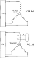
- FIG. 2 illustrates the circuit level distinction between a healthy armature winding and an armature winding with a winding fault.
- Fig. 2A illustrates a healthy armature winding
- Fig. 2B illustrates an armature winding with the winding fault.
- the winding fault creates an asymmetry in the magnetic field which further generates sequence components of the magnetic field.
- Sequence components of magnetic field include a positive sequence component, a negative sequence component and a zero sequence component.
- the negative sequence component of the magnetic field induces a negative sequence back electromotive force (EMF) in the armature winding.
- the negative sequence component typically carries the signature of the winding fault. Knowledge of the negative sequence back EMF may be used to detect the winding fault.
- EMF negative sequence back electromotive force
- the negative sequence back EMF may not be measurable.
- the embodiments presented herein include a method of estimating the negative sequence back EMF manifested in terms of a machine health indicator. Said machine health indicator may be computed based on the negative sequence voltage (Vn) appearing at the terminals of the synchronous machine 102.
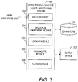
- FIG. 3 illustrates the synchronous machine health monitoring system 108, according to one embodiment.
- the synchronous machine health monitoring system 108 may include a data receiver 302 for receiving data associated with the synchronous machine102.
- the data associated with the synchronous machine 102 may include the phase voltage values and the phase current values of one or more phases, speed, the field current, the power input, the power output, the power factor and the like.
- the data receiver 302 may also convert the phase voltage values into corresponding line voltage values, and phase currents into corresponding line currents.
- the synchronous machine health monitoring system 108 may further include a sequence component module 304 for computing the sequence components of the phase voltage values, and the phase current values.
- the sequence components of phase voltage values may include a positive sequence voltage, a negative sequence voltage (Vn) and a zero sequence voltage.
- the sequence component module 304 may then the sequence components of the voltages and currents, as per the configuration of the synchronous machine. Different configurations of the synchronous machine carry inter-turn fault signatures in different sequence components. For a three phase three wire configuration, or a balanced load configuration, the sequence component module 304 may compute a Vn from the received phase voltage values or line voltage values.
- the sequence component module 304 computes the negative sequence voltage Vn. For an unbalanced load configuration of the synchronous machine 102, the sequence component module 304 computes the negative sequence current In, and the negative sequence impedance Znn, in addition to the Vn. Further, for a three phase four wire configuration of the synchronous machine 102, the sequence component module 304 computes the zero sequence current 10, in addition to the Vn, In, and Znn.
- the synchronous machine health monitoring system 108 may further include a lookup module 306 for retrieving one or more known Vn.
- the known values of one or more Vn may be obtained from the data store 110.
- the data store 110 may include the known and healthy Vn values tabulated as a function of the field current, the positive sequence current at one particular speed, for example.
- the Vn values may correspond to the rated speed of the synchronous machine.
- the lookup module may scale the retrieved Vn based on the measured speed of the synchronous machine.
- the Vn values and the speed of the synchronous machine have a linear relationship with each other.
- the data store 110 may include different sets of known Vn values for different speeds of the synchronous machine 102.
- the lookup module 306 may further include a computing unit for computing the field current and the positive sequence current based on the plurality of phase current values.
- the positive sequence current may be obtained from the plurality of phase current values.
- the field current may be obtained based on the plurality of phase current values and the magnetization characteristic of the synchronous machine 102.
- the magnetization characteristics may be stored in the data store 110.
- the lookup module 306 may retrieve the magnetization characteristics data from the data store 110 for computing the field current.
- the known Vn may be retrieved based on the field current and the positive sequence current.
- the lookup module 306 may further have a query unit for querying the data store 110 using the field current and the positive sequence current.
- the query unit may retrieve the one or more known Vn values, wherein the Vn values may include an open circuit Vn and a healthy state Vn.
- the open circuit Vn may obtained by retrieving that open circuit Vn entry from the lookup table that corresponds the field current computed by the lookup module 306.
- the healthy state Vn is obtained by retrieving that Vn entry from the lookup table that corresponds to the positive sequence current and the field current computed by the lookup module 306.
- the data store 110 may additionally include known In and known Znn values at particular speeds, tabulated as a function of the field current and the positive sequence current.
- the data store 110 may include a known 10 in addition to the known Vn, known In, and known Znn values at particular speeds.
- the lookup module 306 may retrieve the known In, known Zn, and known 10 values using similar techniques as described for retrieving the known Vn.
- the synchronous machine health monitoring system 108 may further include a prognostic module 308 for computing a machine health indicator based on the computed Vn and the one or more known Vn.
- the machine health indicator may be computed by obtaining a phasor difference of the health state Vn and the computed Vn and normalizing the phasor difference with respect to the open circuit Vn.
- the health of the synchronous machine 102 may be assessed based on the machine health indicator.
- the machine health indicator has a specific healthy state value. If the machine health indicator computed by the prognostic module 308 is different from the healthy state value then an inter-turn fault in the armature of the synchronous machine 102, may be indicated.
- the healthy state value of the machine health indicator may be obtained by testing a healthy synchronous machine. Alternately, the healthy state value may be obtained by performing simulations on a model of the synchronous machine 102.
- the system 108 may further include an alarm module 310.
- the alarm module 310 may raise an alarm if the machine health indicator deviates from the healthy state value.
- the fault condition may be indicated through the output device 312.
- the output device 312 may be a display device displaying a warning.
- the display device may be an audio alarm.
- the output device 312 may further be an audiovisual alarm.
- the alarm module 310 may use statistical methods to raise an alarm. For example, the alarm module 310 may monitor the machine health indicator over, say, a 5 minute window. The alarm module 310 may then compute the proportion of the duration for which the machine health indicator deviates from the healthy state value during the 5 minute window. The alarm module 310 may then raise a flag based on the computed proportion. Alternatively, the alarm module 310 may use statistical variability measures such as, but not limited to, standard deviation or statistical mean. The alarm module 310 may compute a mean of the machine health indicator over a 15 minute window, for example. The alarm module 310 may then compare the mean with a healthy state value of the machine health indicator, and raise an alarm if the mean deviates from the healthy state value by a predetermined amount. The use of statistical methods may prevent momentary variations in the machine health indicator from triggering an alarm. This may be useful to reduce false alarms.
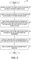
- FIG. 4 is a flowchart illustrating a process 400 for synchronous machine health monitoring, according to an embodiment.
- a plurality of phase voltage values and a plurality of phase current values may be received.
- Other data pertaining to the operation of the synchronous machine 102 may also be received.
- synchronous machine speed, power input, power output, power factor and the like may be received.
- the received phase voltage values may be transformed into line voltage values. It may be appreciated that the line voltage values and the phase voltage values are phasor quantities and have a phase angle associated with them. Therefore the process 400 may associate a particular phase angle to each of the phase voltage values and phase current values. A necessary phase shift should be incorporated while obtaining the line voltage values from the phase voltage values.
- the Vn may be computed based on the phase voltage values.
- the Vn may be computed by multiplying the each of the phase voltage values by a suitable factor and then taking the phasor sum of each of the phase voltage values.
- one or more operating parameters may be computed based on the phase voltage values and the phase current values.
- the one or more operating parameters may be computed based on the line voltage values and the line current values.
- the operating parameters may include the field current, and the positive sequence current.
- the field current may be computed based on the magnetization characteristics and the phase current values.
- the magnetization characteristics data may be retrieved from the data store 110.
- the positive sequence current may be computed based on the phase current values corresponding to the three phases of the synchronous machine 102.
- one or more known Vn values may be obtained based on the one or more operating parameters.
- the known values of one or more Vn may be obtained from the data store 110.
- the data store 110 may include the known Vn values tabulated as a function of the field current, the positive sequence current, for various different values of synchronous machine speed.
- the data store 110 may further have the known Vn values corresponding to a healthy synchronous machine.
- the known values of the Vn may include the healthy state Vn and the healthy open circuit Vn.
- the open circuit Vn may obtained by retrieving that open circuit Vn entry from the lookup table that corresponds to the field current obtained in step 406, and the received value of synchronous machine speed.
- the healthy state Vn is obtained by retrieving that Vn entry from the lookup table which corresponds to the positive sequence current, the field current obtained in step 406, and the received value of synchronous machine speed.
- the synchronous machine health monitoring system 102 may additionally obtain known In and known Znn values. In another embodiment, for prognostics of a three phase four wire configuration, the synchronous machine health monitoring system 102 may obtain a known 10 in addition to the known Vn, known In, and known Znn values.
- the machine health indicator may be computed based on the computed Vn and the one or more known Vn.
- the machine health indicator may be computed by obtaining a phasor difference of the healthy state Vn and the computed Vn and normalizing the phasor difference with respect to the open circuit Vn.
- the health of the synchronous machine 102 may be assessed based on the machine health indicator.
- the machine health indicator has a specific healthy state value. If the machine health indicator computed by the prognostic module 408 is different from the healthy state value then an inter-turn fault in the armature of the synchronous machine 102 may be inferred.
- an alarm may be raised based on the value of the machine health indicator.
- the alarm may be raised by comparing the machine health indicator with a predefined threshold.
- the predefined threshold may be the healthy state value of the machine health indicator. As described in connection with FIG. 3 the alarm may be audio, visual or audiovisual.
- the synchronous machine health monitoring system 108 may be implemented as computer executable instructions.
- the system 108 may have one or more processors for executing the computer executable instructions.
- the computer readable instructions may be embodied into a non-transitory computer readable medium such as a magnetic storage disc, an optical storage disc, and so forth.
- the computer readable medium may be one of a Random Access Memory (RAM), Read Only Memory (ROM), Programmable Read Only Memory (PROM), Erasable Programmable Read Only Memory (EPROM) and the like.
- the coded instructions of the computer program product may include instructions for receiving the plurality of phase voltage values, phase current values, computing Vn based on the plurality of phase voltage values and the plurality of current values, computing the one or more operating parameters based on the phase voltage values and the phase current values.
- the operating parameters may include the field current and the positive sequence current.
- the computer program product may further have coded instructions for converting the phase voltage values into line voltage values.
- the computer program product may further have coded instructions for retrieving the open circuit Vn and the healthy state Vn from the data store 110.
- the computer program product may further have instructions for computing the machine health indicator by obtaining the phasor difference of the healthy state Vn and the computed Vn, and normalizing the phasor difference with respect to the open circuit Vn.
- the computer program product may also have coded instructions for comparing the machine health indicator with the predefine threshold and raising an alarm based on the comparison.
Landscapes
- Engineering & Computer Science (AREA)
- Power Engineering (AREA)
- Physics & Mathematics (AREA)
- General Physics & Mathematics (AREA)
- Tests Of Circuit Breakers, Generators, And Electric Motors (AREA)
- Control Of Eletrric Generators (AREA)
- Remote Monitoring And Control Of Power-Distribution Networks (AREA)
Description
- Embodiments presented herein relate generally to diagnostics of synchronous machines and more specifically to health monitoring of synchronous machines.
- A synchronous machine is one where the rotor rotates at a speed synchronous with the supply alternating current (AC) frequency. A conventional synchronous machine includes laminated armature windings disposed on a stator, and laminated field windings disposed on a rotor. The field winding of the synchronous machine is supplied with Direct Current (DC). Some small synchronous machines use permanent magnets in place of the field winding. Synchronous machines are extensively used in power plants, aviation power systems, power factor correction systems, and so forth.
- Synchronous machines may operate in a generator mode, where an external prime mover rotates the rotor to produce AC power. Alternatively, synchronous machines may operate in a motoring mode, where external AC power generates a rotating magnetic field, thus turning the rotor. In both modes, the armature winding is subjected to a high electrical current and/or voltage during operation. The lamination of the armature windings may degrade with time and prolonged use, thus causing short circuits between successive turns of the armature winding. A short circuit tends to create circulating currents which in turn result in local hot spots within the armature.
- If not detected and repaired in time, such faults may cause unplanned outages. In aviation engines, a failure of the synchronous generator may lead to loss of power to all control and support systems. Therefore, it is important that armature winding faults are detected at incipient stage, to plan appropriate maintenance tasks.
- One known method for synchronous machine health monitoring includes creating a model of the synchronous machine, and simulating synchronous machine operation.
- However, synchronous machine models are created on the assumption that the spatial distribution of windings inside the machine is sinusoidal. The windings of a synchronous machine with an inter-turn fault no longer have a sinusoidal distribution. In other words, the model may not take into account the inherent asymmetry in winding distribution under fault conditions. This may lead to erroneous fault detection.
-
US 6236947 B1 discloses a motor performance analyzer for evaluating and reporting motor condition and performance of an operating motor in which an effective negative sequence impedance is calculated and used to determine a winding fault indicator using baseline values for resistance and impedance.US 5514978 A discloses methods of detecting turn faults in synchronous motors by multiplying a negative sequence current phasor by a characteristic negative sequence impedance, subtracting the result from a negative sequence voltage phasor, and comparing the resulting estimated voltage differential with a threshold. -
-
FIG. 1 is a simplified block diagram illustrating an exemplary environment in which various embodiments may operate; -
FIG. 2A is an exemplary circuit diagram of a healthy synchronous machine, according to one embodiment; -
FIG. 2B is an exemplary circuit diagram of a synchronous machine with winding faults, according to one embodiment; -
FIG. 3 is an exemplary synchronous machine health monitoring system, according to one embodiment; and -
FIG. 4 is a flowchart illustrating an exemplary process of synchronous machine health monitoring, according to one embodiment. - The invention is defined in the appended independent claims with preferred embodiments disclosed in the dependent claims.
- Embodiments presented herein relate to a method and a system for monitoring health of a synchronous machine.
FIG. 1 illustrates anenvironment 100 in which various embodiments may operate. Theenvironment 100 includes asynchronous machine 102, an exciter andcontrol unit 104, amonitoring unit 106, a synchronous machinehealth monitoring system 108 and adata store 110. - The
synchronous machine 102 is an electromechanical energy conversion device where the rotor rotates at the same speed as the rotational speed of a rotating magnetic field. Example synchronous machines include synchronous generators, synchronous motors, and power factor compensators. Thesynchronous machine 102 may be switched between a motoring mode and a generating mode by changing the electrical connections. For instance, in aviation gas turbine engines, thesynchronous machine 102 is an integrated starter-generator. Thesynchronous machine 102 operates in the motoring mode, accepting electrical energy from an onboard battery to start the gas turbine engine. Once the gas turbine engine is fired up, control electronics switch thesynchronous machine 102 to the generating mode, accepting mechanical energy from the gas turbine engine shaft, and generating electrical power for the aircraft. Thesynchronous machine 102 includes a field winding and an armature winding. Typically, in low power and low torque applications thesynchronous machine 102 may be of a rotating armature type including the field winding disposed on the stator, and the armature winding disposed on the rotor. In industrial applications involving high torque and high power, thesynchronous machine 102 may be of a rotating field type including the field winding disposed on the rotor, and the armature winding disposed on the stator. Armature windings are laminated and typically carry a large current. Prolonged usage may degrade the lamination and may cause inter-turn faults. Various embodiments presented herein may be applied to detect inter-turn faults in the armature winding. The embodiments presented herein are described for the rotating field type synchronous machine. However, it should be appreciated that the embodiments may apply equally to all types of synchronous machine. - The exciter and
control unit 104 includes an exciter such as, but not limited to, a DC generator, a battery, a rectified AC supply, or a static exciter, to excite the field windings. The static exciter feeds back a portion of the AC from each phase of generator output to the field windings, as DC excitations, through a system of transformers, rectifiers, and reactors. An external DC source may be used for initial excitation of the field windings. The exciter applies an excitation voltage, herein referred to as field voltage to the field windings of thesynchronous machine 102, thereby causing a field current to flow through the field winding. Due to rotation of the field windings, the flux linked to stationary coils, disposed in a stator of thegenerator 102, varies in a sinusoidal fashion, causing a sinusoidal variation of voltage across the terminals of the stationary coils. The exciter andcontrol unit 104 controls the operation of thegenerator 102. For example, the exciter andcontrol unit 104 may control the field voltage, and field current supplied to thegenerator 102. - The
synchronous machine 102 may be operated and controlled by the exciter andcontrol unit 104. The exciter andcontrol unit 104 may include direct current (DC) power supply, alternating current (AC) power supply, and a control system for controlling the operation of thesynchronous machine 102. The control system may control the field winding voltage so that the voltage at the output remains constant. Further, the control system may control the power delivered to thesynchronous machine 102 or the power delivered from thesynchronous machine 102. The control system may also control the power factor of thesynchronous machine 102. The exciter andcontrol unit 104 controls the operation of thesynchronous machine 102 based on operating data obtained from themonitoring unit 106. - The
monitoring unit 106 may include one or more sensors for obtaining the operating data corresponding to thesynchronous machine 102. The operating data may include phase current values, phase voltage values of one or more phases of thesynchronous machine 102, and the speed of the synchronous machine. The operating data may further include a field current, an input power, an output power, a power factor, for example. The operating data may then be conveyed to the exciter andcontrol unit 104 and the synchronous machinehealth monitoring system 108. The synchronous machinehealth monitoring system 108 has been described in detail in connection withFIG. 3 . - In one embodiment, the
monitoring unit 106, and the exciter andcontrol unit 104 may be included in an integrated excitation, control and monitoring system. Such an integrated excitation, control and monitoring system may be implemented using hardware such as, but not limited to, microcontrollers, microprocessors, logic circuits, and memories; and software modules stored on the memories. - The
environment 100 may further consist of thedata store 110. Thedata store 110 may include data corresponding to the operation of thesynchronous machine 102. For example, thedata store 110 may include a look up table comprising a negative sequence voltage (Vn) of thesynchronous machine 102 as a function of a positive sequence current and the field current at rated speed. Thedata store 110 may further include a magnetization characteristic of the magnetic material used for constructing thesynchronous machine 102. -
FIG. 2 illustrates the circuit level distinction between a healthy armature winding and an armature winding with a winding fault.Fig. 2A illustrates a healthy armature winding andFig. 2B illustrates an armature winding with the winding fault. As shown in shown inFIG. 2B the winding fault creates an asymmetry in the magnetic field which further generates sequence components of the magnetic field. Sequence components of magnetic field include a positive sequence component, a negative sequence component and a zero sequence component. The negative sequence component of the magnetic field induces a negative sequence back electromotive force (EMF) in the armature winding. The negative sequence component typically carries the signature of the winding fault. Knowledge of the negative sequence back EMF may be used to detect the winding fault. - Typically, the negative sequence back EMF may not be measurable. The embodiments presented herein include a method of estimating the negative sequence back EMF manifested in terms of a machine health indicator. Said machine health indicator may be computed based on the negative sequence voltage (Vn) appearing at the terminals of the
synchronous machine 102. -
FIG. 3 illustrates the synchronous machinehealth monitoring system 108, according to one embodiment. The synchronous machinehealth monitoring system 108 may include adata receiver 302 for receiving data associated with the synchronous machine102. The data associated with thesynchronous machine 102 may include the phase voltage values and the phase current values of one or more phases, speed, the field current, the power input, the power output, the power factor and the like. Thedata receiver 302 may also convert the phase voltage values into corresponding line voltage values, and phase currents into corresponding line currents. - The synchronous machine
health monitoring system 108 may further include asequence component module 304 for computing the sequence components of the phase voltage values, and the phase current values. The sequence components of phase voltage values may include a positive sequence voltage, a negative sequence voltage (Vn) and a zero sequence voltage. Thesequence component module 304 may then the sequence components of the voltages and currents, as per the configuration of the synchronous machine. Different configurations of the synchronous machine carry inter-turn fault signatures in different sequence components. For a three phase three wire configuration, or a balanced load configuration, thesequence component module 304 may compute a Vn from the received phase voltage values or line voltage values. For instance, for a three phase three wire configuration or a balance load configuration of thesynchronous machine 102, thesequence component module 304 computes the negative sequence voltage Vn. For an unbalanced load configuration of thesynchronous machine 102, thesequence component module 304 computes the negative sequence current In, and the negative sequence impedance Znn, in addition to the Vn. Further, for a three phase four wire configuration of thesynchronous machine 102, thesequence component module 304 computes the zero sequence current 10, in addition to the Vn, In, and Znn. - The synchronous machine
health monitoring system 108 may further include alookup module 306 for retrieving one or more known Vn. The known values of one or more Vn may be obtained from thedata store 110. Thedata store 110 may include the known and healthy Vn values tabulated as a function of the field current, the positive sequence current at one particular speed, for example. The Vn values may correspond to the rated speed of the synchronous machine. After retrieving the known Vn, the lookup module may scale the retrieved Vn based on the measured speed of the synchronous machine. The Vn values and the speed of the synchronous machine have a linear relationship with each other. Alternatively, thedata store 110 may include different sets of known Vn values for different speeds of thesynchronous machine 102. In an embodiment, thelookup module 306 may further include a computing unit for computing the field current and the positive sequence current based on the plurality of phase current values. The positive sequence current may be obtained from the plurality of phase current values. Similarly, the field current may be obtained based on the plurality of phase current values and the magnetization characteristic of thesynchronous machine 102. The magnetization characteristics may be stored in thedata store 110. Thelookup module 306 may retrieve the magnetization characteristics data from thedata store 110 for computing the field current. In an embodiment, the known Vn may be retrieved based on the field current and the positive sequence current. - The
lookup module 306 may further have a query unit for querying thedata store 110 using the field current and the positive sequence current. The query unit may retrieve the one or more known Vn values, wherein the Vn values may include an open circuit Vn and a healthy state Vn. The open circuit Vn may obtained by retrieving that open circuit Vn entry from the lookup table that corresponds the field current computed by thelookup module 306. Further, the healthy state Vn is obtained by retrieving that Vn entry from the lookup table that corresponds to the positive sequence current and the field current computed by thelookup module 306. - As described above different configurations of the
synchronous machine 102 may carry inter-turn fault signatures in different sequence components. In the implementation for an unbalanced three phase configuration, thedata store 110 may additionally include known In and known Znn values at particular speeds, tabulated as a function of the field current and the positive sequence current. Alternatively, in the implementation for a three phase four wire configuration, thedata store 110 may include a known 10 in addition to the known Vn, known In, and known Znn values at particular speeds. Thelookup module 306 may retrieve the known In, known Zn, and known 10 values using similar techniques as described for retrieving the known Vn. - The synchronous machine
health monitoring system 108 may further include aprognostic module 308 for computing a machine health indicator based on the computed Vn and the one or more known Vn. In an embodiment, the machine health indicator may be computed by obtaining a phasor difference of the health state Vn and the computed Vn and normalizing the phasor difference with respect to the open circuit Vn. The health of thesynchronous machine 102 may be assessed based on the machine health indicator. The machine health indicator has a specific healthy state value. If the machine health indicator computed by theprognostic module 308 is different from the healthy state value then an inter-turn fault in the armature of thesynchronous machine 102, may be indicated. The healthy state value of the machine health indicator may be obtained by testing a healthy synchronous machine. Alternately, the healthy state value may be obtained by performing simulations on a model of thesynchronous machine 102. - The
system 108 may further include analarm module 310. Thealarm module 310 may raise an alarm if the machine health indicator deviates from the healthy state value. The fault condition may be indicated through theoutput device 312. In an embodiment theoutput device 312 may be a display device displaying a warning. In an alternate embodiment, the display device may be an audio alarm. Theoutput device 312 may further be an audiovisual alarm. - In various embodiments, the
alarm module 310 may use statistical methods to raise an alarm. For example, thealarm module 310 may monitor the machine health indicator over, say, a 5 minute window. Thealarm module 310 may then compute the proportion of the duration for which the machine health indicator deviates from the healthy state value during the 5 minute window. Thealarm module 310 may then raise a flag based on the computed proportion. Alternatively, thealarm module 310 may use statistical variability measures such as, but not limited to, standard deviation or statistical mean. Thealarm module 310 may compute a mean of the machine health indicator over a 15 minute window, for example. Thealarm module 310 may then compare the mean with a healthy state value of the machine health indicator, and raise an alarm if the mean deviates from the healthy state value by a predetermined amount. The use of statistical methods may prevent momentary variations in the machine health indicator from triggering an alarm. This may be useful to reduce false alarms. -
FIG. 4 is a flowchart illustrating aprocess 400 for synchronous machine health monitoring, according to an embodiment. In step 402 a plurality of phase voltage values and a plurality of phase current values may be received. Other data pertaining to the operation of thesynchronous machine 102 may also be received. For example, synchronous machine speed, power input, power output, power factor and the like may be received. In an embodiment, the received phase voltage values may be transformed into line voltage values. It may be appreciated that the line voltage values and the phase voltage values are phasor quantities and have a phase angle associated with them. Therefore theprocess 400 may associate a particular phase angle to each of the phase voltage values and phase current values. A necessary phase shift should be incorporated while obtaining the line voltage values from the phase voltage values. - In
step 404 the Vn may be computed based on the phase voltage values. The Vn may be computed by multiplying the each of the phase voltage values by a suitable factor and then taking the phasor sum of each of the phase voltage values. - In
step 406 one or more operating parameters may be computed based on the phase voltage values and the phase current values. In an embodiment, the one or more operating parameters may be computed based on the line voltage values and the line current values. The operating parameters may include the field current, and the positive sequence current. The field current may be computed based on the magnetization characteristics and the phase current values. The magnetization characteristics data may be retrieved from thedata store 110. Further, the positive sequence current may be computed based on the phase current values corresponding to the three phases of thesynchronous machine 102. - In
step 408 one or more known Vn values may be obtained based on the one or more operating parameters. The known values of one or more Vn may be obtained from thedata store 110. Thedata store 110 may include the known Vn values tabulated as a function of the field current, the positive sequence current, for various different values of synchronous machine speed. Thedata store 110 may further have the known Vn values corresponding to a healthy synchronous machine. - The known values of the Vn may include the healthy state Vn and the healthy open circuit Vn. The open circuit Vn may obtained by retrieving that open circuit Vn entry from the lookup table that corresponds to the field current obtained in
step 406, and the received value of synchronous machine speed. Further, the healthy state Vn is obtained by retrieving that Vn entry from the lookup table which corresponds to the positive sequence current, the field current obtained instep 406, and the received value of synchronous machine speed. - In one embodiment, for prognostics of an unbalanced three phase configuration, the synchronous machine
health monitoring system 102 may additionally obtain known In and known Znn values. In another embodiment, for prognostics of a three phase four wire configuration, the synchronous machinehealth monitoring system 102 may obtain a known 10 in addition to the known Vn, known In, and known Znn values. - In
step 410, the machine health indicator may be computed based on the computed Vn and the one or more known Vn. In an embodiment, the machine health indicator may be computed by obtaining a phasor difference of the healthy state Vn and the computed Vn and normalizing the phasor difference with respect to the open circuit Vn. The health of thesynchronous machine 102 may be assessed based on the machine health indicator. The machine health indicator has a specific healthy state value. If the machine health indicator computed by theprognostic module 408 is different from the healthy state value then an inter-turn fault in the armature of thesynchronous machine 102 may be inferred. Instep 412, an alarm may be raised based on the value of the machine health indicator. The alarm may be raised by comparing the machine health indicator with a predefined threshold. The predefined threshold may be the healthy state value of the machine health indicator. As described in connection withFIG. 3 the alarm may be audio, visual or audiovisual. - In various embodiments the synchronous machine
health monitoring system 108 may be implemented as computer executable instructions. Thesystem 108 may have one or more processors for executing the computer executable instructions. The computer readable instructions may be embodied into a non-transitory computer readable medium such as a magnetic storage disc, an optical storage disc, and so forth. Alternatively, the computer readable medium may be one of a Random Access Memory (RAM), Read Only Memory (ROM), Programmable Read Only Memory (PROM), Erasable Programmable Read Only Memory (EPROM) and the like. - The coded instructions of the computer program product may include instructions for receiving the plurality of phase voltage values, phase current values, computing Vn based on the plurality of phase voltage values and the plurality of current values, computing the one or more operating parameters based on the phase voltage values and the phase current values. The operating parameters may include the field current and the positive sequence current. The computer program product may further have coded instructions for converting the phase voltage values into line voltage values. The computer program product may further have coded instructions for retrieving the open circuit Vn and the healthy state Vn from the
data store 110. The computer program product may further have instructions for computing the machine health indicator by obtaining the phasor difference of the healthy state Vn and the computed Vn, and normalizing the phasor difference with respect to the open circuit Vn. The computer program product may also have coded instructions for comparing the machine health indicator with the predefine threshold and raising an alarm based on the comparison. - It may be noted that the voltages and the current, except the field current, disclosed herein are phasor quantities and are manipulated according to the rules of phasor algebra unless explicitly stated otherwise.
Claims (9)
- A method for synchronous machine health monitoring comprising:receiving (402) a plurality of phase voltage values and a plurality of phase current values;computing (404) a negative sequence voltage, Vn, based on the plurality of phase voltage values, wherein the Vn is representative of a negative sequence back electromotive force which carries a signature of a winding fault in a synchronous machine (102);computing (406) one or more operating parameters based on at least one of the plurality of phase voltage values and the plurality of phase current values;retrieving (408) from a data store (110), known Vn based on the one or more operating parameters, the known Vn including a healthy state open circuit Vn and a healthy state Vn;computing (410) a machine health indicator based on the computed Vn and the known Vn, wherein the known Vn may be scaled according to a measured speed of the synchronous machine (102), wherein computing the machine health indicator comprises:computing a phasor difference between the healthy state Vn and the computed Vn; andnormalizing the phasor difference with respect to the healthy state open circuit Vn; and raising (412) an alarm based on the machine health indicator.
- The method of claim 1 further comprising:computing a negative sequence current, In, and a negative sequence impedence, Znn, based on the plurality of phase voltage values and the plurality of phase current values;retrieving from a data store (110), one or more known In, and one or more known Znn based on the one or more operating parameters; andtaking into account the computed In, the computed Znn, the one or more known In, and the one or more known Znn, for computing the machine health indicator.
- The method of claim 2 further comprising:computing a zero sequence current, I0, based on the plurality of phase current values;retrieving from a data store (110), one or more known 10 based on the one or more operating parameters; andtaking into account the computed 10 and the one or more known 10, for computing the machine health indicator.
- A system for synchronous machine health monitoring comprising:a data receiver (302) for receiving a plurality of phase voltage values and a plurality of phase current values;a sequence component module (304) for computing a negative sequence voltage, Vn, based on the plurality of phase voltage values, wherein the Vn is representative of a negative sequence back electromotive force which carries a signature of a winding fault in a synchronous machine (102);a lookup module (306) for retrieving from a data store(110), known Vn based on at least one of the plurality of phase voltage values and the plurality of phase current values, the known Vn including a healthy stateopen circuit Vn and a healthy state Vn;a prognostic module (308) for computing a machine health indicator based on the computed Vn and the known Vn, wherein the known Vn may be scaled according to a measured speed of the synchronous machine (102) and wherein computing the machine health indicator comprises computing a phasor difference between the healthy state Vn and the computed Vn and normalizing the phasor difference with respect to the healthy state open circuit Vn; andan alarm module (310) for raising an alarm based on the machine health indicator.
- The system of claim 4, wherein:the sequence component module (304) further computes at least one of a negative sequence current In, a negative sequence impedence, Znn, and a zero sequence current I0, based on the plurality of phase voltage values and the plurality of phase current values;the lookup module (306) further retrieves at least one of a known In, a known Znn, and a known 10; andthe prognostic module (308) computes the machine health indicator further based on at least one of the computed In, the computed Znn, and the computed 10, the known In, the known Znn, and the known 10.
- The system of either of claim 4 or 5 wherein the lookup module further comprises:a computing unit for computing a field current and a positive sequence current based on the plurality of phase current values; anda query unit for querying the data store using the field current and the positive sequence current.
- A product comprising a non-transitory computer readable medium encoded with computer-executable instructions for monitoring health of a synchronous machine, wherein the computer executable instructions, when executed, cause one or more processors to:receive (402) a plurality of phase voltage values and a plurality of phase current values;compute (404) a negative sequence voltage, Vn, based on the plurality of phase voltage values, wherein the Vn is representative of a negative sequence back electromotive force which carries a signature of a winding fault in a synchronous machine;compute (406) one or more operating parameters based on at least one of the plurality of phase voltage values and the plurality of phase current values;retrieve (408) from a data store, known Vn based on the one or more operating parameters, the known Vn including a healthy stateopen circuit Vn and a healthy state Vn;compute (410) a machine health indicator based on the computed Vn and the known Vn, wherein the known Vn may be scaled according to a measured speed of the synchronous machine; further comprising computer executable instructions to cause the one or more processors to:compute a phasor difference between the healthy state Vn and the computed Vn;normalize the phasor difference with respect to the healthy state open circuit Vn; andraise (412) an alarm based on the machine health indicator.
- The product of claim 7, further comprising computer executable instructions to cause the one or more processors to:compute at least one of a negative sequence current In, a negative sequence impedence Znn, and a zero sequence current I0, based on the plurality of phase voltage values and the plurality of phase current values;retrieve at least one of a known In, a known Znn, and a known 10; andcompute the machine health indicator further based on at least one of the computed In, the computed Znn, and the computed 10, the known In, the known Znn, and the known 10.
- The product of either of claim 7 or claim 8 further comprising computer executable instructions to cause the one or more processors to compute a plurality of voltage phasors based on the plurality of phase voltage values.
Applications Claiming Priority (1)
| Application Number | Priority Date | Filing Date | Title |
|---|---|---|---|
| US12/976,309 US8803461B2 (en) | 2010-12-22 | 2010-12-22 | System and method for synchronous machine health monitoring |
Publications (3)
| Publication Number | Publication Date |
|---|---|
| EP2469703A2 EP2469703A2 (en) | 2012-06-27 |
| EP2469703A3 EP2469703A3 (en) | 2017-02-01 |
| EP2469703B1 true EP2469703B1 (en) | 2020-09-23 |
Family
ID=45495623
Family Applications (1)
| Application Number | Title | Priority Date | Filing Date |
|---|---|---|---|
| EP11192364.5A Active EP2469703B1 (en) | 2010-12-22 | 2011-12-07 | System and method for synchronous machine health monitoring |
Country Status (6)
| Country | Link |
|---|---|
| US (1) | US8803461B2 (en) |
| EP (1) | EP2469703B1 (en) |
| JP (1) | JP6118019B2 (en) |
| CN (1) | CN102608491B (en) |
| BR (1) | BRPI1105177A2 (en) |
| CA (1) | CA2761344C (en) |
Families Citing this family (17)
| Publication number | Priority date | Publication date | Assignee | Title |
|---|---|---|---|---|
| JP5882019B2 (en) * | 2011-10-17 | 2016-03-09 | 株式会社日立製作所 | Inverter-driven rotating electrical machine testing method and rotating electrical machine testing method |
| US20140074413A1 (en) * | 2012-09-13 | 2014-03-13 | General Electric Company | Detection of generator stator inter-circuit faults |
| FR3023628A1 (en) * | 2014-07-10 | 2016-01-15 | Airbus Helicopters | METHOD AND SYSTEM FOR MERGING DEVICE MONITORING INDICATORS |
| WO2016092871A1 (en) | 2014-12-10 | 2016-06-16 | 三菱電機株式会社 | Electric motor diagnosis device |
| GB201616900D0 (en) | 2016-10-05 | 2016-11-16 | Rolls Royce Plc | Brushless synchronous generator stator winding fault |
| EP3306284A1 (en) | 2016-10-10 | 2018-04-11 | Rolls-Royce plc | A method and apparatus for diagnosing a fault condition in an electric machine |
| KR101878810B1 (en) * | 2017-03-08 | 2018-07-16 | 엘지전자 주식회사 | Fault diagnosis method of motor |
| CN107171494B (en) * | 2017-06-15 | 2018-07-20 | 苏州达思灵新能源科技有限公司 | A kind of compressed air turbodynamo system |
| US10895873B2 (en) * | 2018-04-25 | 2021-01-19 | Aktiebolaget Skf | Machine health monitoring of rotating machinery |
| CN109387724B (en) * | 2018-09-30 | 2020-10-27 | 南京理工大学 | Fault diagnosis method for synchronous phase modulator based on longitudinal analysis and transverse correction |
| US11143715B2 (en) * | 2019-08-15 | 2021-10-12 | Schweitzer Engineering Laboratories, Inc. | Broken conductor detection in a multiple-phase electric power delivery system |
| JP7312670B2 (en) * | 2019-10-31 | 2023-07-21 | 株式会社日立産機システム | Rotating equipment diagnostic system and method. |
| EP4109721B1 (en) * | 2020-02-17 | 2024-01-31 | Mitsubishi Electric Corporation | Diagnostic device of permanent magnet synchronous motor, and inverter comprising said diagnostic device |
| CN111917349B (en) * | 2020-06-22 | 2022-06-28 | 广州智能装备研究院有限公司 | Fault diagnosis method and system for permanent magnet synchronous motor |
| KR102425497B1 (en) * | 2020-10-28 | 2022-07-27 | 주식회사 위드피에스 | Synchoronous generator, apparatus and method for monitoring of synchoronous generator, computer-readable storage medium and computer program |
| DE102020215366A1 (en) * | 2020-12-04 | 2022-06-09 | Rolls-Royce Deutschland Ltd & Co Kg | Monitoring method and device for an electric propulsion system |
| JP7461899B2 (en) | 2021-01-08 | 2024-04-04 | 日立建機株式会社 | Maintenance Support System |
Family Cites Families (23)
| Publication number | Priority date | Publication date | Assignee | Title |
|---|---|---|---|---|
| US3723718A (en) | 1970-11-09 | 1973-03-27 | Syst De Corp | Simulation through rotating coordinate transformation |
| SU1591660A1 (en) * | 1988-03-22 | 1991-11-30 | Do Politekh Inst | Method of determining inductive leakage reactance of three-phase synchronic machine |
| US4937530A (en) * | 1988-07-19 | 1990-06-26 | Siemens Aktiengesellschaft | Apparatus for monitoring phase voltages of a polyphase tachometer generator to detect phase failures |
| US5252915A (en) * | 1992-01-23 | 1993-10-12 | Ontario Hydro | Method and apparatus for detecting stator faults in rotary dynamoelectric machines |
| US5270640A (en) * | 1992-04-23 | 1993-12-14 | The Penn State Research Foundation | Method for incipient failure detection in electric machines |
| US5345158A (en) * | 1992-10-02 | 1994-09-06 | General Electric Company | Electrical distribution equipment with torque estimating capability |
| US5612601A (en) * | 1993-11-22 | 1997-03-18 | Martin Marietta Energy Systems, Inc. | Method for assessing motor insulation on operating motors |
| US5477163A (en) * | 1994-08-03 | 1995-12-19 | General Electric Company | Turn fault detection |
| US5514978A (en) * | 1995-03-20 | 1996-05-07 | General Electric Company | Stator turn fault detector for AC motor |
| US5786708A (en) * | 1996-04-01 | 1998-07-28 | General Electric Company | Self-tuning and compensating turn fault detector |
| US6144924A (en) * | 1996-05-20 | 2000-11-07 | Crane Nuclear, Inc. | Motor condition and performance analyzer |
| JP3441634B2 (en) * | 1997-10-02 | 2003-09-02 | 株式会社日立製作所 | Generator motor control device and power generation system using the same |
| US6141196A (en) * | 1998-03-02 | 2000-10-31 | General Electric Company | Method and apparatus for compensation of phasor estimations |
| US20050218906A1 (en) * | 2004-03-31 | 2005-10-06 | Younsi Abdelkrim K | System and method for monitoring of insulation condition |
| ITVA20040055A1 (en) | 2004-11-23 | 2005-02-23 | St Microelectronics Srl | METHOD AND CIRCUIT OF CONTROL OF AN ELECTRICITY GENERATION SYSTEM |
| US7873496B2 (en) | 2005-12-09 | 2011-01-18 | Abb Technology Ltd. | Method and device for fault detection in an N-winding three-phase power transformer |
| CN101087093B (en) * | 2007-06-08 | 2011-01-12 | 哈尔滨工业大学 | Synchronization electromotor with detection coil |
| EP2017632B1 (en) * | 2007-07-19 | 2010-08-25 | ABB Research Ltd. | Method for fault location in uncompensated power lines with two-end unsynchronized measurement |
| JP4458174B2 (en) | 2008-03-21 | 2010-04-28 | 株式会社デンソー | Rotating machine control device and rotating machine control system |
| US8135551B2 (en) * | 2009-02-03 | 2012-03-13 | General Electric Company | Robust on line stator turn fault identification system |
| US8140291B2 (en) * | 2009-02-03 | 2012-03-20 | General Electric Company | Stator turn fault detection apparatus and method for induction machine |
| CN101556307B (en) * | 2009-03-11 | 2011-07-06 | 东北大学 | Permanent magnet synchronous motor control performance automation test system |
| CN101603997B (en) * | 2009-07-03 | 2011-03-30 | 哈尔滨工业大学 | Method for testing parameters of synchronous motor and device for achieving same |
-
2010
- 2010-12-22 US US12/976,309 patent/US8803461B2/en active Active
-
2011
- 2011-12-07 BR BRPI1105177-9A patent/BRPI1105177A2/en not_active Application Discontinuation
- 2011-12-07 EP EP11192364.5A patent/EP2469703B1/en active Active
- 2011-12-08 CA CA2761344A patent/CA2761344C/en not_active Expired - Fee Related
- 2011-12-13 JP JP2011271833A patent/JP6118019B2/en active Active
- 2011-12-22 CN CN201110461564.1A patent/CN102608491B/en active Active
Non-Patent Citations (1)
| Title |
|---|
| None * |
Also Published As
| Publication number | Publication date |
|---|---|
| US8803461B2 (en) | 2014-08-12 |
| JP2012132909A (en) | 2012-07-12 |
| EP2469703A3 (en) | 2017-02-01 |
| US20120161684A1 (en) | 2012-06-28 |
| CA2761344A1 (en) | 2012-06-22 |
| CN102608491B (en) | 2016-04-20 |
| EP2469703A2 (en) | 2012-06-27 |
| CN102608491A (en) | 2012-07-25 |
| BRPI1105177A2 (en) | 2013-04-24 |
| JP6118019B2 (en) | 2017-04-19 |
| CA2761344C (en) | 2019-01-15 |
Similar Documents
| Publication | Publication Date | Title |
|---|---|---|
| EP2469703B1 (en) | System and method for synchronous machine health monitoring | |
| US10042011B2 (en) | Method to detect or monitor the demagnetization of a magnet | |
| Riera-Guasp et al. | Advances in electrical machine, power electronic, and drive condition monitoring and fault detection: State of the art | |
| Da et al. | A new approach to fault diagnostics for permanent magnet synchronous machines using electromagnetic signature analysis | |
| EP2942867B1 (en) | Induction motor speed estimation | |
| EP3480610B1 (en) | Diagnosing a winding set of a stator | |
| EP1930738A2 (en) | Method for detecting an electrical short condition in a dynamoelectric machine | |
| Rosero et al. | On the short-circuiting fault detection in a PMSM by means of stator current transformations | |
| Spyropoulos et al. | A review on the faults of electric machines used in electric ships | |
| CN104871424A (en) | Driving a rotating device based on a combination of speed detection by a sensor and sensor-less speed detection | |
| Irfan et al. | Development of an intelligent condition monitoring system for AC induction motors using PLC | |
| US10082531B2 (en) | Electrical machine component failure detection apparatus and method | |
| Kral et al. | Model-based detection of rotor faults without rotor position sensor-the sensorless Vienna monitoring method | |
| Lee et al. | Diagnosis of interturn short-circuit fault in PMSM by residual voltage analysis | |
| CN102221673A (en) | Method for testing copper loss and temperature rise of multi-phase high-power low-speed permanent magnet synchronous motor | |
| Li et al. | The correlation analysis of PM inter-turn fault based on stator current and vibration signal | |
| KR102212084B1 (en) | Fault diagnosis method of synchronous motor | |
| Asfani et al. | Simulation analysis on high impedance temporary short circuit in induction motor winding | |
| Praneeth et al. | Algorithm for prediction and control of induction motor stator interturn faults in electric vehicles | |
| Eldeeb et al. | Radiated EM Flux Based Diagnostic Approach for Stator Insulation Failures in Inverter Fed Motors | |
| Leboeuf et al. | Fault detection in a current controlled PM drive using back-EMF estimation and residual analysis | |
| Zeng et al. | A New Method to Estimate the Severity of Interturn Short-Circuit Fault for PMSM | |
| Sarikhani et al. | Inter-turn fault diagnosis of PM synchronous generator for variable speed wind applications using floating-space-vector | |
| LOZANOV et al. | Capabilities for Diagnostics of Pump System's Electrical Equipment via Frequency Converters | |
| Khelfi et al. | Dynamic Eccentricity Faut Diagnosis for Inverter-Fed Induction Motor Using Stator Current Temporal Envelope Estimation |
Legal Events
| Date | Code | Title | Description |
|---|---|---|---|
| AK | Designated contracting states |
Kind code of ref document: A2 Designated state(s): AL AT BE BG CH CY CZ DE DK EE ES FI FR GB GR HR HU IE IS IT LI LT LU LV MC MK MT NL NO PL PT RO RS SE SI SK SM TR |
|
| AX | Request for extension of the european patent |
Extension state: BA ME |
|
| PUAI | Public reference made under article 153(3) epc to a published international application that has entered the european phase |
Free format text: ORIGINAL CODE: 0009012 |
|
| PUAL | Search report despatched |
Free format text: ORIGINAL CODE: 0009013 |
|
| AK | Designated contracting states |
Kind code of ref document: A3 Designated state(s): AL AT BE BG CH CY CZ DE DK EE ES FI FR GB GR HR HU IE IS IT LI LT LU LV MC MK MT NL NO PL PT RO RS SE SI SK SM TR |
|
| AX | Request for extension of the european patent |
Extension state: BA ME |
|
| RIC1 | Information provided on ipc code assigned before grant |
Ipc: G01R 31/34 20060101ALI20161223BHEP Ipc: H02P 25/02 20160101AFI20161223BHEP Ipc: H02P 23/14 20060101ALI20161223BHEP |
|
| STAA | Information on the status of an ep patent application or granted ep patent |
Free format text: STATUS: REQUEST FOR EXAMINATION WAS MADE |
|
| 17P | Request for examination filed |
Effective date: 20170801 |
|
| RBV | Designated contracting states (corrected) |
Designated state(s): AL AT BE BG CH CY CZ DE DK EE ES FI FR GB GR HR HU IE IS IT LI LT LU LV MC MK MT NL NO PL PT RO RS SE SI SK SM TR |
|
| STAA | Information on the status of an ep patent application or granted ep patent |
Free format text: STATUS: EXAMINATION IS IN PROGRESS |
|
| 17Q | First examination report despatched |
Effective date: 20180312 |
|
| REG | Reference to a national code |
Ref country code: DE Ref legal event code: R079 Ref document number: 602011068685 Country of ref document: DE Free format text: PREVIOUS MAIN CLASS: H02P0025020000 Ipc: H02P0029024000 |
|
| GRAP | Despatch of communication of intention to grant a patent |
Free format text: ORIGINAL CODE: EPIDOSNIGR1 |
|
| STAA | Information on the status of an ep patent application or granted ep patent |
Free format text: STATUS: GRANT OF PATENT IS INTENDED |
|
| RIC1 | Information provided on ipc code assigned before grant |
Ipc: H02P 23/14 20060101ALI20200327BHEP Ipc: G01R 31/34 20200101ALI20200327BHEP Ipc: H02P 29/024 20160101AFI20200327BHEP |
|
| INTG | Intention to grant announced |
Effective date: 20200415 |
|
| GRAS | Grant fee paid |
Free format text: ORIGINAL CODE: EPIDOSNIGR3 |
|
| GRAA | (expected) grant |
Free format text: ORIGINAL CODE: 0009210 |
|
| STAA | Information on the status of an ep patent application or granted ep patent |
Free format text: STATUS: THE PATENT HAS BEEN GRANTED |
|
| AK | Designated contracting states |
Kind code of ref document: B1 Designated state(s): AL AT BE BG CH CY CZ DE DK EE ES FI FR GB GR HR HU IE IS IT LI LT LU LV MC MK MT NL NO PL PT RO RS SE SI SK SM TR |
|
| REG | Reference to a national code |
Ref country code: GB Ref legal event code: FG4D |
|
| REG | Reference to a national code |
Ref country code: CH Ref legal event code: EP |
|
| REG | Reference to a national code |
Ref country code: DE Ref legal event code: R096 Ref document number: 602011068685 Country of ref document: DE |
|
| REG | Reference to a national code |
Ref country code: IE Ref legal event code: FG4D |
|
| REG | Reference to a national code |
Ref country code: AT Ref legal event code: REF Ref document number: 1317412 Country of ref document: AT Kind code of ref document: T Effective date: 20201015 |
|
| PG25 | Lapsed in a contracting state [announced via postgrant information from national office to epo] |
Ref country code: SE Free format text: LAPSE BECAUSE OF FAILURE TO SUBMIT A TRANSLATION OF THE DESCRIPTION OR TO PAY THE FEE WITHIN THE PRESCRIBED TIME-LIMIT Effective date: 20200923 Ref country code: HR Free format text: LAPSE BECAUSE OF FAILURE TO SUBMIT A TRANSLATION OF THE DESCRIPTION OR TO PAY THE FEE WITHIN THE PRESCRIBED TIME-LIMIT Effective date: 20200923 Ref country code: FI Free format text: LAPSE BECAUSE OF FAILURE TO SUBMIT A TRANSLATION OF THE DESCRIPTION OR TO PAY THE FEE WITHIN THE PRESCRIBED TIME-LIMIT Effective date: 20200923 Ref country code: BG Free format text: LAPSE BECAUSE OF FAILURE TO SUBMIT A TRANSLATION OF THE DESCRIPTION OR TO PAY THE FEE WITHIN THE PRESCRIBED TIME-LIMIT Effective date: 20201223 Ref country code: NO Free format text: LAPSE BECAUSE OF FAILURE TO SUBMIT A TRANSLATION OF THE DESCRIPTION OR TO PAY THE FEE WITHIN THE PRESCRIBED TIME-LIMIT Effective date: 20201223 Ref country code: GR Free format text: LAPSE BECAUSE OF FAILURE TO SUBMIT A TRANSLATION OF THE DESCRIPTION OR TO PAY THE FEE WITHIN THE PRESCRIBED TIME-LIMIT Effective date: 20201224 |
|
| REG | Reference to a national code |
Ref country code: AT Ref legal event code: MK05 Ref document number: 1317412 Country of ref document: AT Kind code of ref document: T Effective date: 20200923 |
|
| PG25 | Lapsed in a contracting state [announced via postgrant information from national office to epo] |
Ref country code: LV Free format text: LAPSE BECAUSE OF FAILURE TO SUBMIT A TRANSLATION OF THE DESCRIPTION OR TO PAY THE FEE WITHIN THE PRESCRIBED TIME-LIMIT Effective date: 20200923 Ref country code: RS Free format text: LAPSE BECAUSE OF FAILURE TO SUBMIT A TRANSLATION OF THE DESCRIPTION OR TO PAY THE FEE WITHIN THE PRESCRIBED TIME-LIMIT Effective date: 20200923 |
|
| REG | Reference to a national code |
Ref country code: NL Ref legal event code: MP Effective date: 20200923 |
|
| REG | Reference to a national code |
Ref country code: LT Ref legal event code: MG4D |
|
| PG25 | Lapsed in a contracting state [announced via postgrant information from national office to epo] |
Ref country code: RO Free format text: LAPSE BECAUSE OF FAILURE TO SUBMIT A TRANSLATION OF THE DESCRIPTION OR TO PAY THE FEE WITHIN THE PRESCRIBED TIME-LIMIT Effective date: 20200923 Ref country code: SM Free format text: LAPSE BECAUSE OF FAILURE TO SUBMIT A TRANSLATION OF THE DESCRIPTION OR TO PAY THE FEE WITHIN THE PRESCRIBED TIME-LIMIT Effective date: 20200923 Ref country code: NL Free format text: LAPSE BECAUSE OF FAILURE TO SUBMIT A TRANSLATION OF THE DESCRIPTION OR TO PAY THE FEE WITHIN THE PRESCRIBED TIME-LIMIT Effective date: 20200923 Ref country code: LT Free format text: LAPSE BECAUSE OF FAILURE TO SUBMIT A TRANSLATION OF THE DESCRIPTION OR TO PAY THE FEE WITHIN THE PRESCRIBED TIME-LIMIT Effective date: 20200923 Ref country code: PT Free format text: LAPSE BECAUSE OF FAILURE TO SUBMIT A TRANSLATION OF THE DESCRIPTION OR TO PAY THE FEE WITHIN THE PRESCRIBED TIME-LIMIT Effective date: 20210125 Ref country code: EE Free format text: LAPSE BECAUSE OF FAILURE TO SUBMIT A TRANSLATION OF THE DESCRIPTION OR TO PAY THE FEE WITHIN THE PRESCRIBED TIME-LIMIT Effective date: 20200923 Ref country code: CZ Free format text: LAPSE BECAUSE OF FAILURE TO SUBMIT A TRANSLATION OF THE DESCRIPTION OR TO PAY THE FEE WITHIN THE PRESCRIBED TIME-LIMIT Effective date: 20200923 |
|
| PG25 | Lapsed in a contracting state [announced via postgrant information from national office to epo] |
Ref country code: PL Free format text: LAPSE BECAUSE OF FAILURE TO SUBMIT A TRANSLATION OF THE DESCRIPTION OR TO PAY THE FEE WITHIN THE PRESCRIBED TIME-LIMIT Effective date: 20200923 Ref country code: AL Free format text: LAPSE BECAUSE OF FAILURE TO SUBMIT A TRANSLATION OF THE DESCRIPTION OR TO PAY THE FEE WITHIN THE PRESCRIBED TIME-LIMIT Effective date: 20200923 Ref country code: AT Free format text: LAPSE BECAUSE OF FAILURE TO SUBMIT A TRANSLATION OF THE DESCRIPTION OR TO PAY THE FEE WITHIN THE PRESCRIBED TIME-LIMIT Effective date: 20200923 Ref country code: IS Free format text: LAPSE BECAUSE OF FAILURE TO SUBMIT A TRANSLATION OF THE DESCRIPTION OR TO PAY THE FEE WITHIN THE PRESCRIBED TIME-LIMIT Effective date: 20210123 Ref country code: ES Free format text: LAPSE BECAUSE OF FAILURE TO SUBMIT A TRANSLATION OF THE DESCRIPTION OR TO PAY THE FEE WITHIN THE PRESCRIBED TIME-LIMIT Effective date: 20200923 |
|
| REG | Reference to a national code |
Ref country code: DE Ref legal event code: R097 Ref document number: 602011068685 Country of ref document: DE |
|
| PG25 | Lapsed in a contracting state [announced via postgrant information from national office to epo] |
Ref country code: SK Free format text: LAPSE BECAUSE OF FAILURE TO SUBMIT A TRANSLATION OF THE DESCRIPTION OR TO PAY THE FEE WITHIN THE PRESCRIBED TIME-LIMIT Effective date: 20200923 |
|
| PLBE | No opposition filed within time limit |
Free format text: ORIGINAL CODE: 0009261 |
|
| REG | Reference to a national code |
Ref country code: CH Ref legal event code: PL |
|
| STAA | Information on the status of an ep patent application or granted ep patent |
Free format text: STATUS: NO OPPOSITION FILED WITHIN TIME LIMIT |
|
| PG25 | Lapsed in a contracting state [announced via postgrant information from national office to epo] |
Ref country code: SI Free format text: LAPSE BECAUSE OF FAILURE TO SUBMIT A TRANSLATION OF THE DESCRIPTION OR TO PAY THE FEE WITHIN THE PRESCRIBED TIME-LIMIT Effective date: 20200923 Ref country code: MC Free format text: LAPSE BECAUSE OF FAILURE TO SUBMIT A TRANSLATION OF THE DESCRIPTION OR TO PAY THE FEE WITHIN THE PRESCRIBED TIME-LIMIT Effective date: 20200923 Ref country code: DK Free format text: LAPSE BECAUSE OF FAILURE TO SUBMIT A TRANSLATION OF THE DESCRIPTION OR TO PAY THE FEE WITHIN THE PRESCRIBED TIME-LIMIT Effective date: 20200923 |
|
| 26N | No opposition filed |
Effective date: 20210624 |
|
| REG | Reference to a national code |
Ref country code: BE Ref legal event code: MM Effective date: 20201231 |
|
| PG25 | Lapsed in a contracting state [announced via postgrant information from national office to epo] |
Ref country code: IT Free format text: LAPSE BECAUSE OF FAILURE TO SUBMIT A TRANSLATION OF THE DESCRIPTION OR TO PAY THE FEE WITHIN THE PRESCRIBED TIME-LIMIT Effective date: 20200923 Ref country code: IE Free format text: LAPSE BECAUSE OF NON-PAYMENT OF DUE FEES Effective date: 20201207 Ref country code: LU Free format text: LAPSE BECAUSE OF NON-PAYMENT OF DUE FEES Effective date: 20201207 |
|
| PG25 | Lapsed in a contracting state [announced via postgrant information from national office to epo] |
Ref country code: LI Free format text: LAPSE BECAUSE OF NON-PAYMENT OF DUE FEES Effective date: 20201231 Ref country code: CH Free format text: LAPSE BECAUSE OF NON-PAYMENT OF DUE FEES Effective date: 20201231 |
|
| PG25 | Lapsed in a contracting state [announced via postgrant information from national office to epo] |
Ref country code: TR Free format text: LAPSE BECAUSE OF FAILURE TO SUBMIT A TRANSLATION OF THE DESCRIPTION OR TO PAY THE FEE WITHIN THE PRESCRIBED TIME-LIMIT Effective date: 20200923 Ref country code: MT Free format text: LAPSE BECAUSE OF FAILURE TO SUBMIT A TRANSLATION OF THE DESCRIPTION OR TO PAY THE FEE WITHIN THE PRESCRIBED TIME-LIMIT Effective date: 20200923 Ref country code: CY Free format text: LAPSE BECAUSE OF FAILURE TO SUBMIT A TRANSLATION OF THE DESCRIPTION OR TO PAY THE FEE WITHIN THE PRESCRIBED TIME-LIMIT Effective date: 20200923 |
|
| PG25 | Lapsed in a contracting state [announced via postgrant information from national office to epo] |
Ref country code: MK Free format text: LAPSE BECAUSE OF FAILURE TO SUBMIT A TRANSLATION OF THE DESCRIPTION OR TO PAY THE FEE WITHIN THE PRESCRIBED TIME-LIMIT Effective date: 20200923 |
|
| PG25 | Lapsed in a contracting state [announced via postgrant information from national office to epo] |
Ref country code: BE Free format text: LAPSE BECAUSE OF NON-PAYMENT OF DUE FEES Effective date: 20201231 |
|
| P01 | Opt-out of the competence of the unified patent court (upc) registered |
Effective date: 20230411 |
|
| PGFP | Annual fee paid to national office [announced via postgrant information from national office to epo] |
Ref country code: GB Payment date: 20231124 Year of fee payment: 13 |
|
| PGFP | Annual fee paid to national office [announced via postgrant information from national office to epo] |
Ref country code: FR Payment date: 20231122 Year of fee payment: 13 Ref country code: DE Payment date: 20231121 Year of fee payment: 13 |