EP2467781B1 - Systems and methods to efficiently schedule commands at a memory controller - Google Patents
Systems and methods to efficiently schedule commands at a memory controller Download PDFInfo
- Publication number
- EP2467781B1 EP2467781B1 EP10742504A EP10742504A EP2467781B1 EP 2467781 B1 EP2467781 B1 EP 2467781B1 EP 10742504 A EP10742504 A EP 10742504A EP 10742504 A EP10742504 A EP 10742504A EP 2467781 B1 EP2467781 B1 EP 2467781B1
- Authority
- EP
- European Patent Office
- Prior art keywords
- memory controller
- command
- commands
- controller port
- link
- Prior art date
- Legal status (The legal status is an assumption and is not a legal conclusion. Google has not performed a legal analysis and makes no representation as to the accuracy of the status listed.)
- Active
Links
- 230000015654 memory Effects 0.000 title claims description 546
- 238000000034 method Methods 0.000 title claims description 52
- 230000009471 action Effects 0.000 claims description 207
- 230000005540 biological transmission Effects 0.000 claims description 80
- 230000004044 response Effects 0.000 claims description 58
- 238000001514 detection method Methods 0.000 claims description 12
- 238000012358 sourcing Methods 0.000 claims description 10
- 238000004590 computer program Methods 0.000 claims description 3
- 230000000977 initiatory effect Effects 0.000 claims description 3
- 238000010586 diagram Methods 0.000 description 24
- 230000003111 delayed effect Effects 0.000 description 7
- 238000012545 processing Methods 0.000 description 7
- 238000013519 translation Methods 0.000 description 7
- 230000000694 effects Effects 0.000 description 3
- 230000003287 optical effect Effects 0.000 description 3
- 230000008569 process Effects 0.000 description 3
- 239000004065 semiconductor Substances 0.000 description 2
- 230000001360 synchronised effect Effects 0.000 description 2
- 238000004891 communication Methods 0.000 description 1
- 125000004122 cyclic group Chemical group 0.000 description 1
- 230000003292 diminished effect Effects 0.000 description 1
- 238000012986 modification Methods 0.000 description 1
- 230000004048 modification Effects 0.000 description 1
- 239000007787 solid Substances 0.000 description 1
Images


Classifications
-
- G—PHYSICS
- G06—COMPUTING; CALCULATING OR COUNTING
- G06F—ELECTRIC DIGITAL DATA PROCESSING
- G06F11/00—Error detection; Error correction; Monitoring
- G06F11/07—Responding to the occurrence of a fault, e.g. fault tolerance
- G06F11/14—Error detection or correction of the data by redundancy in operation
- G06F11/1402—Saving, restoring, recovering or retrying
- G06F11/1405—Saving, restoring, recovering or retrying at machine instruction level
- G06F11/141—Saving, restoring, recovering or retrying at machine instruction level for bus or memory accesses
Definitions
- the present invention relates generally to data communication, and more specifically, to reducing data transmission errors.
- Data transmissions can be significantly affected by errors in the transmission.
- transmission errors may affect a read command sent from a memory controller to a memory redrive device.
- the memory redrive device may transmit a special error indication command alert status frame.
- the alert status frame indicates that the read command was corrupted.
- the memory controller may subsequently perform a corrective action, such as resending the failed command. For instance, the memory controller may replay the read command or retrain the link between the memory controller and the memory redrive device prior to replaying the read command.
- a memory controller When a memory controller is engaged in a corrective action, its ability to process new commands and data is diminished. For example, the memory controller may be unavailable to transmit commands from a requesting agent or to receive data related to the commands. Commands assigned to a memory controller may become backlogged in the memory controller. Such a backlog may increase memory latency. In many instances, memory latency may result in an undesirable decrease in overall system performance. Therefore, there exists a need for improved command scheduling at the memory controller.
- an improved method of scheduling commands at a memory controller includes detecting a transmission error between a first memory controller port and a first redrive device. A first corrective action is initiated at the first memory controller port in response to the detection of the transmission error. The method further includes determining that a second memory controller port initiated a second corrective action. Incoming read commands are distributed based on a comparison of the first corrective action and the second corrective action.
- an improved method of scheduling commands at a memory controller includes determining that a link between a memory controller and a redrive device requires the synchronization command to be transmitted from the memory controller to the redrive device.
- An undesirable half of a core clock cycle may be determined based on a round-trip time of a signal.
- the method further includes scheduling transmission of the synchronization command based on the determination of the undesirable half of the core clock cycle.
- an improved method to schedule commands at a memory controller includes receiving from a memory controller port an indication of a number of queued commands in a read queue of the memory controller port during a cycle. A number of sent commands transmitted to the memory controller port may be tracked. The method further includes determining a predicted number of queued commands in the read queue during a subsequent cycle based on the number of queued commands and the number of sent commands.
- FIG. 1 is a diagram of a first embodiment of a system configured to schedule commands at a memory controller and is generally designated 100.
- the system 100 includes a first redrive device 108, a second redrive device 110, and a memory controller 102.
- the memory controller 102 includes an address translation unit 112, a first memory controller port 104, and a second memory controller port 106.
- the first memory controller port 104 and the first redrive device 108 are connected via a first high speed link.
- the second memory controller port 106 and the second redrive device 110 may be connected via a second high speed link. Each high speed link may refer to two unidirectional high speed links.
- the first memory controller port 104 may transmit to the first redrive device 108 via a southbound link of the first high speed link.
- the first redrive device 108 may transmit to the first memory controller port 104 via a northbound link of the first high speed link.
- the first memory controller port 104 and the second memory controller port 106 access different redrive devices that contain identical memory contents.
- the first memory controller port 104 and the second memory controller port 106 may be mirrored. Data accessed by the first memory controller port 104 and the second memory controller port 106 may be identical.
- the memory controller 102 may compare a first corrective action 122 initiated at the first memory controller port 104 and a second corrective action 124 initiated at the second memory controller port 106. Comparing the corrective actions may include determining a severity of the corrective actions and a sequence in which the corrective actions were initiated. Based on the comparison, the memory controller 102 may determine which of the memory controller ports will be available first for processing incoming read commands 126. Scheduling the incoming read commands 126 to be performed by the memory controller 102 port that is first available may reduce delay caused by the incoming read commands 126. Such incoming read commands 126 may become backlogged at a memory controller port engaged in a corrective action. Minimizing delay at the memory controller ports improves memory latency and increases the overall efficiency of the system 100.
- the memory controller 102 may be configured to detect a transmission error between the first memory controller port 104 and the first redrive device 108.
- the memory controller 102 may be further configured to initiate the first corrective action 122 at the first memory controller port 104 in response to the detection of the transmission error 120.
- the memory controller 102 may determine that the second memory controller port 106 initiated the second corrective action 124.
- the memory controller 102 may distribute the incoming read commands 126 based on the comparison of the first corrective action 122 and the second corrective action 124.
- the first memory controller port 104 may transmit a stream of commands to the first redrive device 108 via the southbound link of the first high speed link.
- the first redrive device 108 may decode and reformat the stream of commands to send to a memory structure (not illustrated) connected to the first redrive device 108.
- the memory structure may retrieve data in response to the command stream and may transmit the data to the first redrive device 108.
- the first redrive device 108 may reformat the data received from the memory structure and transmit the reformatted data to the first memory controller port 104 via the northbound link of the high speed link.
- the first redrive device 108 may detect a transmission error in the command stream received via the southbound link of the first high speed link. For example, the first redrive device 108 may determine that a first command within the command stream contains an uncorrectable error-correcting code (ECC) or a cyclic redundancy check (CRC) error. After detecting the transmission error 120, the first redrive device 108 may drop all subsequent commands in the command stream and return an alert status frame to the first memory controller port 104. The first redrive device 108 may return a stream of alert status frames to the first memory controller port 104 via the northbound link of the first high speed link in response to the transmission error 120.
- ECC uncorrectable error-correcting code
- CRC cyclic redundancy check
- the first memory controller port 104 may use the received alert status frames to detect the transmission error 120 between the first memory controller port 104 and the first redrive device 108. For instance, the first memory controller port 104 may determine that the transmission error 120 occurred in the southbound link of the first high speed link based on the receipt of the alert status frame via the northbound link of the first high speed link.
- the first memory controller port 104 may detect the transmission error 120 in the data received from the first redrive device 108 via the northbound link of the first high speed link.
- the first memory controller port 104 may include logic that checks the data received from the first redrive device 108 for CRC errors.
- the CRC checking may indicate that the data received from the first redrive device 108 contains a transmission error (e.g., the transmission error 120).
- the memory controller 102 may initiate the first corrective action 122 at the first memory controller port 104.
- the first corrective action 122 may be a replay action.
- the replay action may be selected as the first corrective action 122 in instances where the first high speed link is ready for reissuance of the command stream.
- the first memory controller port 104 may issue a link error status reset of the first high speed link.
- the link error status reset may be referred to as a soft reset. If the soft reset is successful in clearing the first high speed link of the alert status frames, then the first high speed link may be ready for reissuance of the command stream.
- the first memory controller port 104 may initiate the replay action as the first corrective action 122.
- the first redrive device 108 may detect the transmission error 120 in the first command of the command stream received via the southbound link of the first high speed link.
- the first redrive device 108 may drop all subsequent commands in the command stream that were received after the first command.
- the first redrive device 108 may not redrive the first command or the subsequent commands to the memory structure.
- the replay action may be used to reissue the command stream to the first redrive to allow the first redrive device 108 to redrive the command stream to the memory structure.
- the first memory controller port 104 may reissue the command stream from a point where the first redrive device 108 terminated the command stream in response to detecting the transmission error 120. In this case, the first memory controller port 104 may reissue the command stream to the first redrive device 108 starting with the first command.
- the first memory controller port 104 may continue to receive alert status frames on the northbound link of the first high speed link after performing the soft reset.
- the first memory controller port 104 may initiate a link retrain action as the first corrective action 122.
- the link retrain action may include retraining the first high speed link between the first memory controller port 104 and the first redrive device 108.
- the first memory controller port 104 may perform the replay action after the link retrain action has prepared the first high speed link for the receipt of the reissued commands. For example, after the first high speed link is retrained, the first memory controller port 104 may reissue the command stream from a point where the first redrive device 108 terminated the command stream in response to detecting the transmission error 120.
- the first memory controller port 104 may initiate the first corrective action 122 in response to the detection of the transmission error 120 in the northbound link of the first high speed link. For instance, the first memory controller port 104 may detect a CRC error in the data received via the northbound link of the first high speed link. The first memory controller port 104 may determine that a second command in the command stream issued via the southbound link of the first high speed link resulted in the corrupted data in the northbound link. For example, the first memory controller port 104 may initiate the replay action by reissuing the command stream to the first redrive device 108 via the southbound link of the first high speed link starting with the second command.
- the memory controller 102 may determine whether the second memory controller port 106 initiated a corrective action (e.g., the second corrective action 124). In response to detecting the second corrective action 124, the memory controller 102 may compare the first corrective action 122 and the second corrective action 124. Comparing the corrective actions may include determining a severity of each of the corrective actions and determining which corrective action was initiated first. The severity of the corrective action may be based on a number of clock cycles needed to perform the corrective action. The link retrain action may take more clock cycles to perform than the replay action and is therefore more severe.
- a corrective action e.g., the second corrective action 124
- Comparing the corrective actions may include determining a severity of each of the corrective actions and determining which corrective action was initiated first. The severity of the corrective action may be based on a number of clock cycles needed to perform the corrective action. The link retrain action may take more clock cycles to perform than the replay action and is therefore more severe.
- the memory controller 102 may indicate which corrective action will be completed first.
- the memory controller may also indicate the order in which the memory controller ports will become available for processing normal traffic (e.g., the incoming read commands 126). In mirrored mode, the incoming read commands may be distributed to either memory controller port.
- the memory controller 102 may distribute the incoming read commands 126 based on the comparison of the first corrective action 122 and the second corrective action 124.
- the address translation unit 112 may distribute the incoming read commands 126. For instance, the address translation unit 112 may determine based on the comparison that the second memory controller port 106 will complete the second corrective action 124 before the first memory controller port 104 will complete the first corrective action 122.
- the address translation unit 112 may direct the incoming read commands 126 to the second memory controller port 106. Directing the incoming read commands 126 to the second memory controller port 106 may prevent the incoming read commands 126 from being stalled on the first memory controller port 104 as the first memory controller port 104 completes the first corrective action 122. Preventing the incoming read commands 126 from becoming delayed may improve memory latency. In applications where the system 100 is streaming audio or video, preventing read commands from becoming backlogged at a memory controller port may prevent potentially noticeable effects such as gaps in the audio or the video.
- FIG. 2 is a diagram of a second embodiment of a system to schedule commands at a memory controller and is generally designated 200.
- the system 200 includes many elements found in the system 100 referred to in FIG. 1 , where similar elements have the same reference number.
- the first memory controller port 104 may transmit a stream of commands to the first redrive device 108 via the southbound link of the first high speed link.
- the first redrive device 108 may decode and reformat the stream of commands to send to a memory structure (not illustrated) connected to the first redrive device 108.
- the memory structure may retrieve data in response to the command stream and may transmit the data to the first redrive device 108.
- the first redrive device 108 may reformat the data received from the memory structure and transmit the reformatted data to the first memory controller port 104 via the northbound link of the first high speed link.
- the first redrive device 108 may detect a transmission error in the command stream received via the southbound link of the first high speed link. For instance, the first redrive device 108 may determine that a first command within the command stream contains an ECC or CRC single bit error. After detecting the transmission error 120 the first redrive device 108 may drop all subsequent commands in the command stream and return an alert status frame to the first memory controller port 104.
- the first redrive device 108 may return a stream of alert status frames to the first memory controller port 104 via the northbound link of the first high speed link in response to the transmission error 120.
- the first memory controller port 104 may use the received alert status frames to detect the transmission error 120 between the first memory controller port 104 and the first redrive device 108. For example, the first memory controller port 104 may determine that the transmission error 120 occurred in the southbound link of the first high speed link based on the receipt of the alert status frame via the northbound link of the first high speed link.
- the first memory controller port 104 may detect the transmission error 120 in the data received from the first redrive device 108 via the northbound link.
- the first memory controller port 104 may include logic that checks the data received from the first redrive device 108 for CRC errors.
- the CRC checking may indicate that the data received from the first redrive device 108 contains a transmission error (e.g., the transmission error 120).
- the memory controller 102 may initiate the first corrective action 222 at the first memory controller port 104.
- the first corrective action 222 may be a replay action.
- the replay action may be selected as the first corrective action 222 in instances where the first high speed link is ready for reissuance of the command stream. For instance, after receiving the alert status frame the first memory controller port 104 may issue a soft reset of the first high speed link.
- the first high speed link may be ready for reissuance of the command stream.
- the first memory controller port 104 may initiate the replay action as the first corrective action 222.
- the first redrive device 108 may detect the transmission error 120 in the first command of the command stream received via the southbound link of the first high speed link.
- the first redrive device 108 may drop all subsequent commands in the command stream that were received after the first command.
- the first redrive device 108 may not redrive the first command or the subsequent commands to the memory structure.
- the replay action may be used to reissue the command stream to the first redrive to allow the first redrive device 108 to redrive the command stream to the memory structure.
- the first memory controller port 104 may reissue the command stream from a point where the first redrive device 108 terminated the command stream in response to the transmission error 120.
- the first memory controller port 104 may reissue the command stream to the first redrive device 108 starting with the first command.
- the first memory controller port 104 may continue to receive alert status frames on the northbound link of the first high speed link after performing the soft reset.
- the first memory controller port 104 may initiate a link retrain action as the first corrective action 222.
- the link retrain action may include retraining the first high speed link between the first memory controller port 104 and the first redrive device 108.
- the first memory controller port 104 may perform the replay action after the link retrain action has prepared the first high speed link for the receipt of the reissued commands. For instance, after the first high speed link is retrained, the first memory controller port 104 may reissue the command stream from a point where the first redrive device 108 terminated the command stream in response to detecting the transmission error 120.
- the first memory controller port 104 may initiate the first corrective action 222 in response to the detection of the transmission error 120 in the northbound link of the first high speed link. For example, the first memory controller port 104 may detect a CRC error in the data received via the northbound link of the first high speed link. The first memory controller port 104 may determine that a second command in the command stream issued via the southbound link of the first high speed link resulted in the corrupted data in the northbound link of the first high speed link. For instance, the first memory controller port 104 may initiate the replay action by reissuing the command stream to the first redrive device 108 via the southbound link of the first high speed link starting with the second command.
- the memory controller 102 may determine whether the second memory controller port 106 initiated a corrective action (e.g., the second corrective action 224). In response to detecting the second corrective action 224, the memory controller 102 may compare the first corrective action 222 and the second corrective action 224. Comparing the corrective actions may include determining a severity of each of the corrective actions and determining which corrective action was initiated first.
- the severity of the corrective action may be based on a number of clock cycles needed to perform a corrective action.
- the link retrain action takes more clock cycles to perform than the replay action and is therefore more severe.
- the memory controller 102 may indicate which corrective action will be completed first and the order in which the memory controller ports will become available for processing normal traffic (e.g., the incoming read commands 226).
- the memory controller 102 may distribute the incoming read commands 226 based on the comparison of the first corrective action 222 and the second corrective action 224. For example, the memory controller 102 may determine based on the comparison that the second memory controller port 106 will complete the second corrective action 224 before the first memory controller port 104 will complete the first corrective action 222. The memory controller 102 may direct the incoming read commands 226 to the second memory controller port 106.
- the memory controller 102 may distribute the incoming read commands 226 to the second memory controller port 106 in response to a comparison.
- the comparison may indicate that the second corrective action 224 initiated a second replay action before the first corrective action 222 initiated a first replay action.
- Directing the incoming read commands 226 to the second memory controller port 106 may prevent the incoming read commands 226 from being stalled on the first memory controller port 104 as the first memory controller port 104 completes the first corrective action 222. Preventing the incoming read commands 226 from becoming delayed may improve memory latency. For example, in applications where the system 200 is streaming audio or video, preventing read commands from becoming backlogged at a memory controller port may prevent potentially noticeable effects such as gaps in the audio or the video.
- FIG. 3 is a diagram of a third embodiment of a system to schedule commands at a memory controller and is generally designated 300.
- the system 300 includes many elements found in the system 100 referred to in FIG. 1 , where similar elements have the same reference number.
- the first memory controller port 104 may transmit a stream of commands to the first redrive device 108 via the southbound link of the first high speed link.
- the first redrive device 108 may decode and reformat the stream of commands to send to a memory structure (not illustrated) connected to the first redrive device 108.
- the memory structure may retrieve data in response to the command stream and may transmit the data to the first redrive device 108.
- the first redrive device 108 may reformat the data received from the memory structure and transmit the reformatted data to the first memory controller port 104 via the northbound link of the first high speed link.
- the first redrive device 108 may detect a transmission error in the command stream received via the southbound link. For instance, the first redrive device 108 may determine that a first command within the command stream contains a single bit error. After detecting the transmission error 120 the first redrive device 108 may drop all subsequent commands in the command stream and return an alert status frame to the first memory controller port 104.
- the first redrive device 108 may return a stream of alert status frames to the first memory controller port 104 via the northbound link of the first high speed link in response to the transmission error 120.
- the first memory controller port 104 may use the received alert status frames to detect the transmission error 120 between the first memory controller port 104 and the first redrive device 108. For example, the first memory controller port 104 may determine that the transmission error 120 occurred in the southbound link of the first high speed link. This determination may be based on the receipt of the alert status frame via the northbound link of the first high speed link.
- the first memory controller port 104 may detect the transmission error 120 in the data received from the first redrive device 108 via the northbound link of the first high speed link.
- the first memory controller may include logic that checks the data received from the first redrive device 108 for CRC errors.
- the CRC checking may indicate that the data received from the first redrive device 108 may contain a transmission error (e.g., the transmission error 120).
- the memory controller 102 may initiate the first corrective action 322 at the first memory controller port 104.
- the first corrective action 322 is a replay action.
- the replay action may be selected as the first corrective action 322 where the first high speed link is ready for reissuance of the command stream.
- the first memory controller port 104 may issue a soft reset of the first high speed link. If the soft reset is successful in clearing the first high speed link of the alert status frames then the first high speed link may be ready for reissuance of the command stream.
- the first memory controller port 104 may initiate the replay action as the first corrective action 322.
- the first redrive device 108 may detect the transmission error 120 in the first command of the command stream received via the southbound link of the first high speed link.
- the first redrive device 108 may drop all subsequent commands in the command stream that were received after the first command.
- the first redrive device 108 may not redrive the first command or the subsequent commands to the memory structure.
- the replay action may be used to reissue the command stream to the first redrive to allow the first redrive device 108 to redrive the command stream to the memory structure.
- the first memory controller port 104 may reissue the command stream from a point where the first redrive device 108 terminated the command stream in response to detecting the transmission error 120.
- the first memory controller port 104 may reissue the command stream to the first redrive device 108 starting with the first command.
- the first high speed link may not be ready to receive the reissued commands via the replay action.
- the first memory controller port 104 may continue to receive alert status frames on the northbound link of the first high speed link after performing the soft reset.
- the first memory controller port 104 may initiate a link retrain action as the first corrective action 322.
- the link retrain action may include retraining the first high speed link between the first memory controller port 104 and the first redrive device 108.
- the first memory controller port 104 may execute the replay action after the link retrain action has prepared the first high speed link for the receipt of the reissued commands. For instance, after the first high speed link is retrained, the first memory controller port 104 may reissue the command stream from a point where the first redrive device 108 terminated the command stream in response to detecting the transmission error 120.
- the first memory controller port 104 may initiate the first corrective action 322 in response to the detection of the transmission error 120 in the northbound link of the first high speed link. For example, the first memory controller port 104 may detect a CRC error in the data received via the northbound link of the first high speed link. The first memory controller port 104 may determine that a second command in the command stream issued via the southbound link of the first high speed link resulted in the corrupted data in the northbound link of the first high speed link. For instance, the first memory controller port 104 may initiate the replay action by reissuing the command stream to the first redrive device 108 via the southbound link of the first high speed link starting with the second command.
- the memory controller 102 may determine whether the second memory controller port 106 initiated a corrective action (e.g., the second corrective action 324). In response to detecting the second corrective action 324, the memory controller 102 may compare the first corrective action 322 and the second corrective action 324. Comparing the corrective actions may include determining a severity of each of the corrective actions and determining which corrective action was initiated first.
- the severity of the corrective action may be an indication of how many clock cycles a memory controller would take to perform the corrective action.
- the link retrain action may take more clock cycles to perform that the replay action and therefore is more severe.
- the memory controller 102 may indicate which corrective action will be completed first and the order in which the memory controller ports will become available for processing normal traffic (e.g., the incoming read commands 326).
- the memory controller 102 may distribute the incoming read commands 326 based on the comparison of the first corrective action 322 and the second corrective action 324. For instance, the memory controller 102 may determine based on the comparison that the first corrective action 322 is a link retrain action and the second corrective action 324 is a replay action.
- the link retrain action may be more severe than the replay action because the link retrain action takes longer to perform.
- the memory controller 102 may determine that the second memory controller port 106 will complete the second corrective action 324 (i.e., the replay action) before the first memory controller port 104 will complete the first corrective action 322 (i.e., the link retrain action).
- the memory controller 102 may direct the incoming read commands 326 to the second memory controller port 106. Directing the incoming read commands 326 to the second memory controller port 106 may prevent the incoming read commands 326 from being stalled on the first memory controller port 104 as the first memory controller port 104 completes the first corrective action 322. Preventing the incoming read commands 326 from becoming delayed may improve memory latency. For example, in applications where the system 300 is streaming audio or video, preventing read commands from becoming backlogged at a memory controller port may prevent potentially noticeable effects such as gaps in the audio or the video.
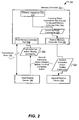
- a diagram of a first embodiment of a method to schedule commands at a memory controller is illustrated and is generally designated 400.
- the method 400 commences in start state 401.
- a first memory controller port may determine whether an alert status frame is received on a link between the first memory controller port and a first redrive device. If the first memory controller port may not receive the alert status frames, the logic returns to block 402. If an alert status frame is received, the first memory controller port performs a soft reset, at block 404. Thereafter, the first memory controller port may determine at block 406 whether the link is clear of alert status frames. If so, the first memory controller port may initiate at block 408 a first replay action at the first memory controller port.
- the first memory controller port may indicate to an address translation unit at block 410 that the first replay action is in progress at the first memory controller port.
- the memory controller may determine whether a second memory controller port is engaged in a replay action (e.g., the second replay action). If the second memory controller port is not engaged in the second replay action, the logic proceeds to block 416. If the second memory controller is engaged in the second replay action, the logic proceeds to block 414.
- the memory controller determines whether the second memory controller port initiated the second replay action before the first memory controller port initiated the first replay action. If the second memory controller port initiated the second replay action before the first memory controller port in the first replay action, the memory controller directs incoming read commands at block 418 to the second memory controller port.
- the first memory controller port may determine whether the first memory controller port has completed the first replay action. If the first memory controller port has completed the first replay action, the memory controller directs the incoming read commands at block 422 to both the first memory controller port and the second memory controller port. The logic may end at state 434.
- the logic returns to the block 420. If the second memory controller port did not initiate the second replay action before the first memory controller port initiated the first replay action at block 414, the memory controller may direct the incoming read commands at block 436 to the first memory controller port.
- the memory controller may determine whether the second memory controller port has completed the second replay action. If so, the memory controller may direct at block 422 the incoming read commands to both the first memory controller port and the second memory controller port. The logic may end at state 434. At block 438, if the second memory controller port has not completed the second reply action, the logic returns to block 438.
- the memory controller may determine whether the second memory controller port is engaged in a retrain of a link between the second memory controller port and a second redrive device. If the second memory controller port initiated the second link retrain action, the memory controller may direct at block 440 the incoming read commands to the first memory controller port. At block 445, the memory controller determines whether the second memory controller port is in retrain. If the second memory controller port is in retrain, the logic returns to block 445. If the second memory controller port has completed the retrain, the memory controller at block 422 may direct the incoming read commands to both the first memory controller port and the second memory controller port. The logic may end at state 434.
- the memory controller at block 418 may direct the incoming read commands to the second memory controller port.
- the first memory controller port may determine whether the first memory controller port has completed the first replay action. If the first memory controller port has not completed the first replay action, the logic returns to the block 420. If the first memory controller port has completed the first replay action, the memory controller at block 422 may direct the incoming read commands to both the first memory controller port and the second memory controller port. The logic may end at state 434.
- the first memory controller port initiates at block 424 the first link retrain action between the first memory controller port and the first redrive device.
- the first memory controller port indicates to the address translation unit that the first memory controller port has initiated the first link retrain, at block 426.
- the memory controller determines at block 428 whether the second memory controller port is engaged in the second link retrain action.
- the memory controller at block 422 may direct the incoming read commands to both the first memory controller port and the second memory controller port. The logic ends at state 434.
- the logic proceeds to block 430 and the memory controller may direct the incoming read commands to the second memory controller port.
- the memory controller determines whether the first memory controller port has completed the first link retrain action. If the first memory controller port has not completed the first link retrain action, the logic returns to block 432. If the first memory controller port has completed retraining the link between the first memory controller port and the first redrive device, the first memory controller port initiates the first replay action at block 408 at the first memory controller port. The first memory controller port indicates to an address translation unit at block 410 that the first replay action is in progress at the first memory controller port.
- the memory controller determines whether a second memory controller port is engaged in the second replay action. If the second memory controller port has not initiated the second replay action, the logic proceeds to block 416. If the second memory controller has initiated the second replay action, the logic proceeds to block 414.
- the memory controller may determine whether the second memory controller port initiated the second replay action before the first memory controller port initiated the first replay action. If the second memory controller port initiated the replay action before the first memory controller port, the logic proceeds to block 418 and the memory controller directs incoming read commands to the second memory controller port.
- the first memory controller port may determine at block 420 whether the first memory controller port has completed the first replay action. If the first memory controller port has completed the first replay action, the memory controller at block 422 may direct the incoming read commands to both the first memory controller port and the second memory controller port. The logic may end at state 434. If the first memory controller port has not completed the replay action, the logic may return to block 420 until the first replay action at the first memory controller port is complete.
- the memory controller directs at block 436 the incoming read commands to the first memory controller port.
- the memory controller may determine whether the second memory controller port has completed the second replay action. If so, the memory controller directs at block 422 the incoming read commands to both the first memory controller port and the second memory controller port. The logic may end at state 434. At block 438, if the second memory controller port has not completed the second reply action, the logic may return to block 438.
- the memory controller may determine whether the second memory controller port is engaged in a retrain of a link between the second memory controller port and a second redrive device. If the second memory controller port initiated the second link retrain action, the memory controller may direct at block 440 the incoming read commands to the first memory controller port. At block 445, the memory controller determines whether the second memory controller port is in retrain. If the second memory controller port is in retrain, the logic returns to block 445. If the second memory controller port has completed the retrain, the memory controller at block 422 may direct the incoming read commands to both the first memory controller port and the second memory controller port. The logic may end at state 434.
- the memory controller at block 418 may direct the incoming read commands to the second memory controller port.
- the first memory controller port determines whether the first memory controller port has completed the first replay action. If the first memory controller port has not completed the first replay action, the logic returns to the block 420. If the first memory controller port has completed the first replay action, the memory controller at block 422 may direct the incoming read commands to both the first memory controller port and the second memory controller port. The logic may end at state 434.
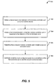
- FIG. 5 is a flow diagram of a second embodiment of a method 500 of scheduling commands at a memory controller.
- the method 500 may be executed by any of the systems of FIGS. 1-3 , or any combination thereof.
- the method 500 may include detecting a transmission error between a first memory controller port and a first redrive device, at block 502.
- the memory controller 102 of FIGS. 1-3 may detect the transmission error 120 between the first memory controller port 104 and the first redrive device 108.
- the method 500 may also include initiating a first corrective action at the first memory controller port in response to the detection of the transmission error, at block 504.
- the memory controller 102 of FIGS. 1-3 initiates the first corrective action 122 at the first memory controller port 104 in response to the detection of the transmission error 120.
- the method 500 further includes determining that a second memory controller port initiated a second corrective action, at block 506.
- the memory controller 102 of FIGS. 1-3 may determine that the second memory controller port 106 initiated the second corrective action 124.
- the method 500 may also include distributing incoming read commands based on a comparison of the first corrective action and the second corrective action, at block 508.
- the memory controller 102 of FIGS. 1-3 distributes the incoming read commands 126 based on the comparison of the first corrective action 122 and the second corrective action 124.
- FIG. 6 is a diagram of a fourth embodiment of a system configured to schedule commands at a memory controller and is generally designated 600.
- the system 600 includes a memory controller 602 and a redrive device 604 connected via a link 606.
- the link 606 refers to two unidirectional high speed links.
- the memory controller 602 may transmit to the redrive device 604 via a southbound link
- the redrive device 604 may transmit to the memory controller 602 via a northbound link.
- the memory controller 602 may include a core clock domain and a datalink layer domain that are synchronous in nature, but not actually the same frequency.
- the core clock domain and the datalink layer may be multiples of one another.
- the core clock domain may include the portions of the memory controller 602 that perform processes based on a core clock 610.
- the datalink layer domain may include the portions of the memory controller 602 that perform processes based on a memory clock.
- the memory controller 602 may receive data from the redrive device 604 via the link 606 based on the memory clock. After the data is received in the datalink layer domain, the memory controller 602 may align the data to the core clock 610 before transmitting via the core clock domain the data to a processor that is synchronized with the core clock 610.
- alignment with the core clock domain may include delaying first data received in the datalink layer domain during a second half of the core clock cycle by half a core clock cycle.
- the first data received during the second half of the core clock cycle may not be transmitted to the core clock domain until the next first half of the core clock cycle.
- Delaying the first data until the next first half of the core clock cycle may delay second data received during the next first half of the core clock cycle by half a core clock cycle. This delay may, in turn, delay third data received during a following second half of the core clock cycle.
- Fourth data received during a following first half of the core clock cycle may also be delayed, as well as fifth data received during a following second half of the core clock cycle.
- a gap may form between the second data and the fourth data.
- the delayed second data may fill the half core clock cycle gap without delaying the fourth data. Therefore, the first data, second data, fourth data, and fifth data may be transmitted efficiently to the core clock domain without the gap.
- the memory controller 602 may schedule transmission of commands to result in a sequence of data that when aligned to the core clock 610 may be transmitted to the core clock domain without the gap. Scheduling the commands to result in gapless data may include scheduling a synchronization command 608 to be transmitted on an undesirable half of the core clock cycle. Scheduling the synchronization command 608 on the undesirable half of the core clock cycle may include determining which half of the core clock cycle transmission on which would produce data that may be transmitted without the gap. Efficiently scheduling the commands at the memory controller 602 to prevent gaps in data during core clock alignment may improve the efficiency of the memory controller 602 and reduces memory latency.
- the memory controller 602 may be configured to determine that the link 606 between the memory controller 602 and the redrive device 604 requires the synchronization command 608 to be transmitted from the memory controller 602 to the redrive device 604.
- the memory controller 602 may be configured to determine the undesirable half of the core clock cycle based on a round-trip time 618 of a signal.
- the memory controller 602 is configured to schedule transmission of the synchronization command 608 based on the determination of the undesirable half of the core clock cycle.
- the memory controller 602 may determine that the link 606 between the memory controller 602 and the redrive device 604 requires a synchronization command (e.g., the synchronization command 608). Determining that the link 606 requires the synchronization command 608 may include the memory controller 602 determining a number of frames transmitted over the link. The memory controller 602 may compare the number of frames transmitted over the link 606 to an upper threshold and a lower threshold.
- a synchronization command e.g., the synchronization command 608
- the upper threshold may be the maximum number of frames that can be transmitted over the link 606 before the synchronization command 608 must be transmitted to maintain link synchronization.
- the lower threshold may be the minimum number of frames that must be transmitted before the synchronization command 608 is transmitted.
- the lower threshold may be forty-two frames and the upper threshold may be eighty-four frames.
- the memory controller 602 may determine that the link 606 requires the synchronization command 608 to be transmitted at some point before the eighty-fourth frame is transmitted. For instance, to maintain link synchronization, the memory controller 602 may transmit the synchronization command 608 on the southbound link to the redrive device 604 between the forty-second frame and the eighty-fourth frame.
- the memory controller 602 may schedule the transmission of the synchronization command 608. Scheduling the synchronization command 608 may include determining which half of the core clock cycle to transmit the synchronization command 608.
- Determining which half of the core clock cycle to transmit the synchronization command 608 may include determining the desirable half and the undesirable half.
- the desirable half of the core clock cycle may refer to the half of the core clock cycle upon which transmission of a particular command results in data that arrives at the memory controller 602 on the first half of the core clock cycle. Data that arrives at the first half of the core clock cycle is aligned with the core clock domain and therefore may not create the delay.
- the desirable half of the core clock cycle results in efficient receipt of data at the memory controller 602.
- the undesirable half of the core clock cycle may refer to the half of the core clock cycle upon which transmission of the particular command results in data that arrives at the memory controller 602 on the second half of the core clock cycle. Data that arrives at the second half of the core clock cycle is not aligned with the core clock domain and therefore may create the delay. In this case, transmitting commands on the undesirable half of the core clock cycle may result in inefficient receipt of the data at the memory controller 602.
- Determining which half of the core clock cycle is the undesirable half is based on the round-trip time 618 of a signal.
- the memory controller 602 may determine the number of core clock cycles between the particular command being issued to the redrive device 604 and the data in response to the particular command arriving at the memory controller 602.
- wire delay may contribute to the round-trip time 618.
- Receiver, internal logic, cross chip wire, and driver delay in the redrive device 604 may contribute to the round-trip time 618.
- the round-trip time 618 between issuance of the particular command and the data arriving in response may be eight full core clock cycles and one half core clock cycle. If the particular command was issued on the first half of the core clock cycle, data would have returned on the second half of the core clock cycle. Data returned on the second half of the core clock cycle creates the delay. In this case, the first half of the core clock cycle is the undesirable half.
- the memory controller 602 may determine the number of memory clocks between the particular command being issued to the redrive device 604 and the data in response to the particular command arriving at the memory controller 602.
- the memory clock is twice as fast as the core clock 610.
- the round-trip time 618 between issuance of the particular command and the data arriving in response may be seventeen memory clocks.
- the round-trip time 618 was nine full core clock cycles, issuance of the particular command on the second half of the core clock cycle would result in data returned on the second half of the core clock cycle. In this case, the second half of the core clock cycle is the undesirable half.
- the memory controller 602 stores the determination of which half of the core clock cycle is the undesirable half. Storing the determination may allow the memory controller 602 to avoid having to make the determination every time the requirement for the synchronization command 608 is detected.
- the memory controller 602 may re-determine which half of the core clock cycle is the undesirable half after the link 606 is retrained. For example, retraining the link 606 may impact the round-trip delay of the signal due to thermal or voltage drift.
- the memory controller 602 may re-determine periodically which half of the core clock cycle is the undesirable half. For instance, the memory controller 602 may perform the determination after a pre-set number of core clocks have occurred subsequent to a previous determination.
- Scheduling transmission of the synchronization command 608 based on the undesirable half of the core clock cycle may include transmitting the synchronization command 608 on the undesirable half of the core clock cycle. Transmitting the synchronization command 608 to the redrive device 604 on the undesirable half may result in the synchronization status arriving at the memory controller 602 on the second half of the core clock cycle. The synchronization status is extracted in the datalink layer of the memory controller 602 and is not used in the core clock domain. If the synchronization status is received by the memory controller 602 on the second half of the core clock cycle, then data received before the synchronization status may be delayed by a half of the core clock cycle without delaying the data received after the synchronization status.
- the memory controller 602 may prevent overhead associated with issuing the synchronization command. Reducing the synchronization overhead may improve the efficiency of the memory controller 602 and reduce memory latency.
- FIG. 7 is a diagram of a fifth embodiment of a system to schedule commands at a memory controller 602 and is generally designated 700.
- the system 700 includes many elements found in the system 600 referred to in FIG. 6 , where similar elements include the same reference number.
- the determination of which half of the core clock cycle 730 is an undesirable half 728 may be based on a round-trip time 732 of a signal.
- the round-trip time 732 of the signal may be the number of core clock cycles between a particular command 722 being issued to the redrive device 604 and data 724 in response to the particular command 722 arriving at the memory controller 602.
- the round-trip time 732 of the signal may be determined based on the number of memory clock cycle between the particular command 722 being issued to the redrive device 604 and the data 724 in response to the particular command 722 arriving at the memory controller 602.
- the memory controller 602 may determine that the round-trip time 732 is equivalent to an even number of memory clock cycles. For example, the round-trip time 732 between issuance of the particular command 722 and the data 724 arriving in response to the particular command 722 may be eighteen memory clock cycles. Eighteen memory clock cycles may correspond to nine full core clock cycles 730 when the memory clock is twice as fast as the core clock. Transmitting the particular command 722 on the second half of the core clock cycle 730 may result in the data 724 in response arriving at the memory controller 602 on the second half of the core clock cycle 730. Data arriving at the second half of the core clock cycle 730 is not aligned with the core clock domain and therefore may create delay. Because the transmission of the particular command 722 on the second half of the core clock cycle results in data 724 on the second half of the core clock cycle, the second half of the core clock cycle is the undesirable half 728.
- the memory controller 602 may prevent overhead associated with issuing the synchronization command. Reducing the synchronization overhead may improve the efficiency of the memory controller 602 and reduce memory latency.
- FIG. 8 is a diagram of a sixth embodiment of a system to schedule commands at a memory controller 602 and is generally designated 800.
- the system 800 includes many elements found in the system 600 referred to in FIG. 6 , where similar elements include the same reference number.
- the determination of which half of the core clock cycle 830 is an undesirable half 826 may be based on a round-trip time 832 of a signal.
- the round-trip time 832 of the signal may be the number of core clock cycles between a particular command 822 being issued to the redrive device 604 and data 824 in response to the particular command 822 arriving at the memory controller 602.
- the round-trip time 832 of the signal may be determined based on the number of memory clock cycle between the particular command 822 being issued to the redrive device 604 and the data 824 in response to the particular command 822 arriving at the memory controller 602.
- the memory controller 602 may determine that the round-trip time 832 is equivalent to an odd number of memory clock cycles. For instance, the round-trip time 832 between issuance of the particular command 822 and the data 824 arriving in response to the particular command 822 may be seventeen memory clock cycles. Seventeen memory clock cycles may correspond to eight full core clock cycles 830 and one half core clock cycle 830 when the memory clock 820 is twice as fast as the core clock 610. Transmitting the particular command 822 on the first half of the core clock cycle 830 results in the data 824 in response arriving at the memory controller 602 on the second half of the core clock cycle 830. Data arriving at the second half of the core clock cycle 830 is not aligned with the core clock domain and therefore may create delay. Because the transmission of the particular command 822 on the first half of the core clock cycle results in data 824 on the second half of the core clock cycle, the first half of the core clock cycle is the undesirable half 828.
- the memory controller 602 may prevent overhead associated with issuing the synchronization command. Reducing the synchronization overhead may improve the efficiency of the memory controller 602 and reduce memory latency.
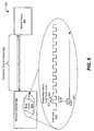
- FIG. 9 is a diagram of a seventh embodiment of a system to schedule commands at a memory controller and is generally designated 900.
- the system 900 includes many elements found in the system 600 referred to in FIG. 6 , where similar elements include the same reference number.
- the memory controller determines that the round-trip time 956 of a signal is seventeen memory clock 920 cycles. Based on the determination that the round-trip time 956 is an odd number, the memory controller may determine that the first half is the undesirable half 964 of the core clock 610 cycle. In response, the memory controller may schedule the transmission of the synchronization command 944 on the first half 964 of the core clock 610 cycle.
- the synchronization command 944 may be replaced with any command that results in non-data that may be extracted in the datalink layer. For example, the memory controller may transmit a first command 940 on the undesirable half 964 and a second command 942 on a desirable half 966 of the core clock 610 cycle.
- the memory controller may transmit the synchronization command 944 on the undesirable half 964, a third command 946 on the desirable half 966, and a fourth command 948 on the undesirable half 964.
- the memory controller may receive first data 950 at a physical layer of the memory controller in response to the first command 940 and the second command 942.
- the memory controller may receive a synchronization status 952 in response to the synchronization command 944, and second data 954 in response to the third command 946 and the fourth command 948.
- frames arriving at the memory controller from the redrive device may follow a sequence where a first portion of the first data 950 arrives when the core clock 610 is on the second half of the core clock cycle.
- a second portion of the first data 950 may arrive when the core clock 610 is on a following first half of the core clock cycle.
- the synchronization status 952 may arrive when the core clock 610 is on a next second half of the core clock cycle.
- a first portion of the second data 954 may arrive when the core clock 610 is on a next first half of the core clock cycle.
- a second portion of the second data 954 may arrive when the core clock 610 is on a next second half of the core clock cycle.
- the memory controller may extract 958 the synchronization status 952 at the data link layer of the memory controller.
- the synchronization status 952 may only be used in the data link layer of the memory controller and may not be transmitted to the core clock domain of the memory controller.
- a gap may be created between the first data 950 and the second data 954.
- the memory controller may delay 960 the first data 950 by a half core clock cycle to align the first data 950 with the core clock domain. For example, if the first portion of the first data 950 arrived on the second half of the core clock 610 cycle, the core clock domain of the memory controller may not receive the first portion of the first data 950 until a next half of the core clock cycle (i.e., the first half).
- the memory controller may read the first data 950. With the synchronization status extracted and the second data 954 aligned with the core clock domain, the memory controller may read the second data 954 during a following first half of the core clock cycle. The memory controller may gather 962 the first data 950 and the second data 954 within two core clock cycles despite the half core clock cycle between issuance of the second command 942 and issuance of the third command 946.
- data e.g., the first data 950
- data received before the synchronization status 952 may be delayed by a half of the core clock cycle without delaying the data (e.g., the second data 954) received after the synchronization status 952.
- the memory controller 602 may schedule commands to prevent gaps in data during a core clock alignment. Preventing gaps during the core clock alignment may improve the efficiency of the memory controller 602 and reduce memory latency.
- FIG. 10 is a flow diagram of a third embodiment of a method 1000 to schedule commands at a memory controller.
- the method 1000 is performed by any of the systems of FIGS. 6-9 , or any combination thereof.
- the method 1000 includes determining that a link between a memory controller and a redrive device requires the synchronization command to be transmitted from the memory controller to the redrive device, at 1002. For instance, the memory controller 602 of FIG. 6 determines that the link 606 between the memory controller 602 and the redrive device 604 requires the synchronization command 608 to be transmitted from the memory controller 602 to the redrive device 604.
- the method 1000 may also include determining an undesirable half of a core clock cycle based on a round-trip time of a signal, at block 1004.
- the memory controller 602 of FIG. 6 determines the undesirable half (612 or 614) of the core clock 610 cycle based on the round-trip time 618 of the signal.
- the memory controller 602 of FIG. 7 determines the undesirable half 728 of the core clock cycle 730 based on the round-trip time 732.
- the memory controller 602 of FIG. 8 determines the undesirable half 826 of the core clock cycle 830 based on the round-trip time 832.
- the method 1000 further includes scheduling transmission of the synchronization command based on the determination of the undesirable half of the core clock cycle, at 1006.
- a memory controller may schedule transmission of the synchronization command 608 of FIG. 6 based on the determination of the undesirable half (612 or 614) of the core clock 610 cycle.
- scheduling of the transmission of the synchronization command 944 of FIG. 9 based on the determination of the undesirable half 964 of the core clock cycle.
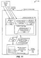
- FIG. 11 is a diagram of an eighth embodiment of a system to schedule commands at a memory controller and is generally designated 1100.
- the system 1100 includes a memory controller 1102 with a memory controller unit 1104 and a memory controller port 1108.
- the memory controller unit 1104 includes prediction logic 1106 and the memory controller port 1108 includes a read queue 1110.
- the memory controller unit 1104 utilizes information gathered from multiple locations to predict the number of queued commands 1134 in the read queue 1110. Speculatively determining when the read queue 1110 is full allows the memory controller unit 1104 to provide efficient backpressure to sourcing agents 1140. Improving the accuracy of the predictions of a read queue status allows the memory controller 1102 to fill more of the read queue 1110. Filling more of the read queue 1110 improves utilization of the read queue 1110 and the overall efficiency of the memory controller 1102.
- the memory controller 1102 is configured to receive from the memory controller port 1108 an indication 1120 of a number 1132 of queued commands in the read queue 1110 of the memory controller port 1108 during a cycle.
- the memory controller may be configured to track a number 1126 of sent commands 1128 transmitted to the memory controller port 1108.
- the memory controller 1102 may be configured to determine a predicted number 1130 of queued commands 1134 in the read queue during a subsequent cycle based on the number 1132 of queued commands in the cycle and the number 1126 of sent commands 1128.
- the memory controller unit 1104 may transmit commands 1128 to the memory controller port 1108.
- the memory controller unit 1104 may track the number 1126 of the commands 1128 sent to the memory controller port 1108.
- the memory controller port 1108 determines the number 1132 of queued commands in the read queue during the cycle.
- the memory controller port 1108 may send to the memory controller unit 1104 the indication 1120 of the number 1132 of queued commands in the read queue during the cycle.
- the memory controller unit 1104 may determine the predicted number 1130 of queued commands 1134 in the read queue during the subsequent cycle. The determination may be based on the number 1132 of queued commands during the cycle and the number 1126 of sent commands.
- the prediction logic 1106 of the memory controller unit 1104 may predict the number 1130 of queued commands 1134 in the read queue during the subsequent cycle. For example, the prediction logic 1106 may determine the predicted number 1130 of queued commands 1134 in the read queue during the subsequent cycle is ten when the number 1126 of sent commands is two and the number 1132 of queued commands in the read queue during the cycle is nine. In this case, the prediction logic 1106 predicted that one command was issued from the read queue 1110 between the cycle and the subsequent cycle.
- the memory controller unit 1104 may determine whether to prevent subsequent commands from being directed to the memory controller port 1108. The determination may be based on the predicted number 1130 of queued commands in the read queue during the subsequent cycle and a maximum read queue capacity.
- the maximum read queue may be a maximum number of commands that the read queue 1110 can hold. For instance, the memory controller unit 1104 may prevent the subsequent commands from being directed to the memory controller port 1108 when the predicted number 1130 of queued commands in the read queue during the subsequent cycle is ten and the maximum read queue capacity is twelve.
- the memory controller unit 1104 may receive incoming commands 1124 from the sourcing agents 1140.
- the incoming commands 1124 may originate from a processor port, a scalability port, a request handler, or a pending queue.
- the memory controller may be able to ignore requests from some sourcing agents and have to take requests from other sourcing agents. For example, the memory controller may ignore fastpath requests.
- the memory controller unit 1104 may determine a number 1122 of the incoming commands 1124 received.
- the memory controller unit 1104 may apply backpressure to the sourcing agents 1140 based on the predicted number 1130 of queued commands in the read queue during the subsequent cycle and the number 1122 of incoming commands 1124.
- the backpressure may include signals that direct an individual sourcing agent to stop sending the incoming commands 1124.
- the memory controller unit 1104 may apply the backpressure to the sourcing agents 1140 when the predicted number 1130 of queued commands in the read queue during the subsequent cycle is ten and the number 1122 of incoming commands 1124 is five. Applying the backpressure to the sourcing agents 1140 prevents the read queue 1110 in the memory controller port 1108 from overfilling.
- Speculatively determining when the read queue 1110 is full allows the memory controller unit 1104 to efficiently provide the backpressure to the sourcing agents 1140 and better predict the status of the read queue 1110. Improving the accuracy of predictions related to the status of the read queue 1110 may allow the memory controller 1102 to fill more of the read queue 1110. Filling more of the read queue 1110 improves the utilization of the read queue 1110 and increases the overall efficiency of the memory controller 1102.
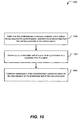
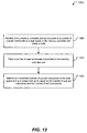
- FIG. 12 is a flow diagram of fourth embodiment of a method 1200 to schedule commands at a memory controller.
- the method 1300 is performed by any of the systems of FIG. 11 .
- the method includes receiving from a memory controller port an indication of a number of queued commands in the read queue of the memory controller port during a cycle, at block 1202.
- the memory controller unit 1104 of FIG. 11 receives from the memory controller port 1108 the indication 1120 of the number 1132 of queued commands in the read queue 1110 during the cycle.
- the method 1200 also includes tracking a number of sent commands transmitted to the memory controller port, at block 1206. For instance, the memory controller unit 1104 of FIG. 11 tracks the number 1126 of the sent commands 1128.
- the method 1200 also includes determining a predicted number of queued commands in the read queue during a subsequent cycle based on the number of queued commands and the number of sent commands, at block 1208. For example, the prediction logic 1106 of the memory controller unit 1104 of FIG. 11 determines the predicted number 1130 of the queued commands 1134 in the read queue during a subsequent cycle based on the number 1132 of queued commands in the read queue during the cycle and the number 1126 of sent commands 1128.
- Particular embodiments can take the form of an entirely hardware embodiment, an entirely software embodiment or an embodiment containing both hardware and software elements.
- the disclosed methods are implemented in software, which includes but is not limited to firmware, resident software, microcode, etc.
- embodiments can take the form of a computer program product accessible from a computer-usable or computer-readable medium providing program code for use by or in connection with a computer or any instruction execution system.
- a computer-usable or computer readable medium can be any apparatus that can contain, store, communicate, propagate, or transport the program for use by or in connection with the instruction execution system, apparatus, or device.
- the medium can be an electronic, magnetic, optical, electromagnetic, infrared, or semiconductor system (or apparatus or device) or a propagation medium.
- Examples of a computer-readable medium include a semiconductor or solid state memory, magnetic tape, a removable computer diskette, a random access memory (RAM), a read-only memory (ROM), a rigid magnetic disk and an optical disk.
- Current examples of optical disks include compact disc - read only memory (CD-ROM), compact disc - read/write (CD-R/W) and DVD.
- a data processing system suitable for storing and/or executing program code will include at least one processor coupled directly or indirectly to memory elements through a system bus.
- the memory elements can include local memory employed during actual execution of the program code, bulk storage, and cache memories which provide temporary storage of at least some program code in order to reduce the number of times code must be retrieved from bulk storage during execution.
- I/O devices including but not limited to keyboards, displays, pointing devices, etc.
- I/O controllers can be coupled to the system either directly or through intervening I/O controllers.
- Network adapters may also be coupled to the system to enable the data processing system to become coupled to other data processing systems or remote printers or storage devices through intervening private or public networks.
- Modems, cable modems, and Ethernet cards are just a few of the currently available types of network adapters.
Landscapes
- Engineering & Computer Science (AREA)
- Theoretical Computer Science (AREA)
- Quality & Reliability (AREA)
- Physics & Mathematics (AREA)
- General Engineering & Computer Science (AREA)
- General Physics & Mathematics (AREA)
- Data Exchanges In Wide-Area Networks (AREA)
- Debugging And Monitoring (AREA)
Description
- The present invention relates generally to data communication, and more specifically, to reducing data transmission errors.
- Data transmissions can be significantly affected by errors in the transmission. For example, transmission errors may affect a read command sent from a memory controller to a memory redrive device. In response to a detected error, the memory redrive device may transmit a special error indication command alert status frame. The alert status frame indicates that the read command was corrupted. The memory controller may subsequently perform a corrective action, such as resending the failed command. For instance, the memory controller may replay the read command or retrain the link between the memory controller and the memory redrive device prior to replaying the read command.
- When a memory controller is engaged in a corrective action, its ability to process new commands and data is diminished. For example, the memory controller may be unavailable to transmit commands from a requesting agent or to receive data related to the commands. Commands assigned to a memory controller may become backlogged in the memory controller. Such a backlog may increase memory latency. In many instances, memory latency may result in an undesirable decrease in overall system performance. Therefore, there exists a need for improved command scheduling at the memory controller.
- In a particular embodiment, an improved method of scheduling commands at a memory controller is disclosed. The method includes detecting a transmission error between a first memory controller port and a first redrive device. A first corrective action is initiated at the first memory controller port in response to the detection of the transmission error. The method further includes determining that a second memory controller port initiated a second corrective action. Incoming read commands are distributed based on a comparison of the first corrective action and the second corrective action.
- In another particular embodiment, an improved method of scheduling commands at a memory controller is disclosed. The method includes determining that a link between a memory controller and a redrive device requires the synchronization command to be transmitted from the memory controller to the redrive device. An undesirable half of a core clock cycle may be determined based on a round-trip time of a signal. The method further includes scheduling transmission of the synchronization command based on the determination of the undesirable half of the core clock cycle.
- In another particular embodiment, an improved method to schedule commands at a memory controller is disclosed. The method includes receiving from a memory controller port an indication of a number of queued commands in a read queue of the memory controller port during a cycle. A number of sent commands transmitted to the memory controller port may be tracked. The method further includes determining a predicted number of queued commands in the read queue during a subsequent cycle based on the number of queued commands and the number of sent commands.
- These and other advantages and features that characterize the invention are set forth in the claims annexed hereto and forming a further part hereof. However, for a better understanding of the invention, and of the advantages attained through its use, reference should be made to the drawings and to the accompanying descriptive matter in which there are described exemplary embodiments of the invention.
-
FIG. 1 is a block diagram of a first embodiment of a system to schedule commands at a memory controller; -
FIG. 2 is a block diagram of a second embodiment of a system to schedule commands at a memory controller; -
FIG. 3 is a block diagram of a third embodiment of a system to schedule commands at a memory controller; -
FIG. 4 is a flow diagram of a first embodiment of a method to schedule commands at a memory controller; -
FIG. 5 is a flow diagram of a second embodiment of a method to schedule commands at a memory controller; -
FIG. 6 is a block diagram of a fourth embodiment of a system to schedule commands at a memory controller; -
FIG. 7 is a block diagram of a fifth embodiment of a system to schedule commands at a memory controller; -
FIG. 8 is a block diagram of a sixth embodiment of a system to schedule commands at a memory controller; -
FIG. 9 is a block diagram of a seventh embodiment of a system to schedule commands at a memory controller; -
FIG. 10 is a flow diagram of third embodiment of a method to schedule commands at a memory controller; -
FIG. 11 is a block diagram of an eighth embodiment of a system to schedule commands at a memory controller; and -
FIG. 12 is a flow diagram of a fourth embodiment of a method to schedule commands at a memory controller. -
FIG. 1 is a diagram of a first embodiment of a system configured to schedule commands at a memory controller and is generally designated 100. The system 100 includes afirst redrive device 108, asecond redrive device 110, and amemory controller 102. Thememory controller 102 includes anaddress translation unit 112, a firstmemory controller port 104, and a secondmemory controller port 106. In a particular embodiment, the firstmemory controller port 104 and thefirst redrive device 108 are connected via a first high speed link. The secondmemory controller port 106 and thesecond redrive device 110 may be connected via a second high speed link. Each high speed link may refer to two unidirectional high speed links. For instance, the firstmemory controller port 104 may transmit to the first redrivedevice 108 via a southbound link of the first high speed link. Thefirst redrive device 108 may transmit to the firstmemory controller port 104 via a northbound link of the first high speed link. - In a particular embodiment, the first
memory controller port 104 and the secondmemory controller port 106 access different redrive devices that contain identical memory contents. For example, the firstmemory controller port 104 and the secondmemory controller port 106 may be mirrored. Data accessed by the firstmemory controller port 104 and the secondmemory controller port 106 may be identical. - The
memory controller 102 may compare a firstcorrective action 122 initiated at the firstmemory controller port 104 and a secondcorrective action 124 initiated at the secondmemory controller port 106. Comparing the corrective actions may include determining a severity of the corrective actions and a sequence in which the corrective actions were initiated. Based on the comparison, thememory controller 102 may determine which of the memory controller ports will be available first for processingincoming read commands 126. Scheduling theincoming read commands 126 to be performed by thememory controller 102 port that is first available may reduce delay caused by theincoming read commands 126. Suchincoming read commands 126 may become backlogged at a memory controller port engaged in a corrective action. Minimizing delay at the memory controller ports improves memory latency and increases the overall efficiency of the system 100. - The
memory controller 102 may be configured to detect a transmission error between the firstmemory controller port 104 and thefirst redrive device 108. Thememory controller 102 may be further configured to initiate the firstcorrective action 122 at the firstmemory controller port 104 in response to the detection of thetransmission error 120. Thememory controller 102 may determine that the secondmemory controller port 106 initiated the secondcorrective action 124. Thememory controller 102 may distribute the incoming read commands 126 based on the comparison of the firstcorrective action 122 and the secondcorrective action 124. - The first
memory controller port 104 may transmit a stream of commands to thefirst redrive device 108 via the southbound link of the first high speed link. Thefirst redrive device 108 may decode and reformat the stream of commands to send to a memory structure (not illustrated) connected to thefirst redrive device 108. The memory structure may retrieve data in response to the command stream and may transmit the data to thefirst redrive device 108. Thefirst redrive device 108 may reformat the data received from the memory structure and transmit the reformatted data to the firstmemory controller port 104 via the northbound link of the high speed link. - The
first redrive device 108 may detect a transmission error in the command stream received via the southbound link of the first high speed link. For example, thefirst redrive device 108 may determine that a first command within the command stream contains an uncorrectable error-correcting code (ECC) or a cyclic redundancy check (CRC) error. After detecting thetransmission error 120, thefirst redrive device 108 may drop all subsequent commands in the command stream and return an alert status frame to the firstmemory controller port 104. Thefirst redrive device 108 may return a stream of alert status frames to the firstmemory controller port 104 via the northbound link of the first high speed link in response to thetransmission error 120. The firstmemory controller port 104 may use the received alert status frames to detect thetransmission error 120 between the firstmemory controller port 104 and thefirst redrive device 108. For instance, the firstmemory controller port 104 may determine that thetransmission error 120 occurred in the southbound link of the first high speed link based on the receipt of the alert status frame via the northbound link of the first high speed link. - The first
memory controller port 104 may detect thetransmission error 120 in the data received from thefirst redrive device 108 via the northbound link of the first high speed link. For example, the firstmemory controller port 104 may include logic that checks the data received from thefirst redrive device 108 for CRC errors. For instance, the CRC checking may indicate that the data received from thefirst redrive device 108 contains a transmission error (e.g., the transmission error 120). - In response to the detection of the
transmission error 120, thememory controller 102 may initiate the firstcorrective action 122 at the firstmemory controller port 104. The firstcorrective action 122 may be a replay action. The replay action may be selected as the firstcorrective action 122 in instances where the first high speed link is ready for reissuance of the command stream. For example, after receiving the alert status frame, the firstmemory controller port 104 may issue a link error status reset of the first high speed link. Alternatively, the link error status reset may be referred to as a soft reset. If the soft reset is successful in clearing the first high speed link of the alert status frames, then the first high speed link may be ready for reissuance of the command stream. The firstmemory controller port 104 may initiate the replay action as the firstcorrective action 122. For instance, thefirst redrive device 108 may detect thetransmission error 120 in the first command of the command stream received via the southbound link of the first high speed link. - In response to detecting the
transmission error 120, thefirst redrive device 108 may drop all subsequent commands in the command stream that were received after the first command. Thefirst redrive device 108 may not redrive the first command or the subsequent commands to the memory structure. The replay action may be used to reissue the command stream to the first redrive to allow thefirst redrive device 108 to redrive the command stream to the memory structure. For example, the firstmemory controller port 104 may reissue the command stream from a point where thefirst redrive device 108 terminated the command stream in response to detecting thetransmission error 120. In this case, the firstmemory controller port 104 may reissue the command stream to thefirst redrive device 108 starting with the first command. - However, if the soft reset is not successful in clearing the first high speed link of the alert status frames then the first high speed link may not be ready to receive the reissued commands during the replay action. For instance, the first
memory controller port 104 may continue to receive alert status frames on the northbound link of the first high speed link after performing the soft reset. The firstmemory controller port 104 may initiate a link retrain action as the firstcorrective action 122. The link retrain action may include retraining the first high speed link between the firstmemory controller port 104 and thefirst redrive device 108. The firstmemory controller port 104 may perform the replay action after the link retrain action has prepared the first high speed link for the receipt of the reissued commands. For example, after the first high speed link is retrained, the firstmemory controller port 104 may reissue the command stream from a point where thefirst redrive device 108 terminated the command stream in response to detecting thetransmission error 120. - Alternatively, the first
memory controller port 104 may initiate the firstcorrective action 122 in response to the detection of thetransmission error 120 in the northbound link of the first high speed link. For instance, the firstmemory controller port 104 may detect a CRC error in the data received via the northbound link of the first high speed link. The firstmemory controller port 104 may determine that a second command in the command stream issued via the southbound link of the first high speed link resulted in the corrupted data in the northbound link. For example, the firstmemory controller port 104 may initiate the replay action by reissuing the command stream to thefirst redrive device 108 via the southbound link of the first high speed link starting with the second command. - In response to detecting the
transmission error 120 in the first high speed link via the southbound link or the northbound link, thememory controller 102 may determine whether the secondmemory controller port 106 initiated a corrective action (e.g., the second corrective action 124). In response to detecting the secondcorrective action 124, thememory controller 102 may compare the firstcorrective action 122 and the secondcorrective action 124. Comparing the corrective actions may include determining a severity of each of the corrective actions and determining which corrective action was initiated first. The severity of the corrective action may be based on a number of clock cycles needed to perform the corrective action. The link retrain action may take more clock cycles to perform than the replay action and is therefore more severe. Based on the comparison, thememory controller 102 may indicate which corrective action will be completed first. The memory controller may also indicate the order in which the memory controller ports will become available for processing normal traffic (e.g., the incoming read commands 126). In mirrored mode, the incoming read commands may be distributed to either memory controller port. - The
memory controller 102 may distribute the incoming read commands 126 based on the comparison of the firstcorrective action 122 and the secondcorrective action 124. Theaddress translation unit 112 may distribute the incoming read commands 126. For instance, theaddress translation unit 112 may determine based on the comparison that the secondmemory controller port 106 will complete the secondcorrective action 124 before the firstmemory controller port 104 will complete the firstcorrective action 122. Theaddress translation unit 112 may direct the incoming read commands 126 to the secondmemory controller port 106. Directing the incoming read commands 126 to the secondmemory controller port 106 may prevent the incoming read commands 126 from being stalled on the firstmemory controller port 104 as the firstmemory controller port 104 completes the firstcorrective action 122. Preventing the incoming read commands 126 from becoming delayed may improve memory latency. In applications where the system 100 is streaming audio or video, preventing read commands from becoming backlogged at a memory controller port may prevent potentially noticeable effects such as gaps in the audio or the video. -
FIG. 2 is a diagram of a second embodiment of a system to schedule commands at a memory controller and is generally designated 200. Thesystem 200 includes many elements found in the system 100 referred to inFIG. 1 , where similar elements have the same reference number. - The first
memory controller port 104 may transmit a stream of commands to thefirst redrive device 108 via the southbound link of the first high speed link. Thefirst redrive device 108 may decode and reformat the stream of commands to send to a memory structure (not illustrated) connected to thefirst redrive device 108. The memory structure may retrieve data in response to the command stream and may transmit the data to thefirst redrive device 108. Thefirst redrive device 108 may reformat the data received from the memory structure and transmit the reformatted data to the firstmemory controller port 104 via the northbound link of the first high speed link. - The
first redrive device 108 may detect a transmission error in the command stream received via the southbound link of the first high speed link. For instance, thefirst redrive device 108 may determine that a first command within the command stream contains an ECC or CRC single bit error. After detecting thetransmission error 120 thefirst redrive device 108 may drop all subsequent commands in the command stream and return an alert status frame to the firstmemory controller port 104. - The
first redrive device 108 may return a stream of alert status frames to the firstmemory controller port 104 via the northbound link of the first high speed link in response to thetransmission error 120. The firstmemory controller port 104 may use the received alert status frames to detect thetransmission error 120 between the firstmemory controller port 104 and thefirst redrive device 108. For example, the firstmemory controller port 104 may determine that thetransmission error 120 occurred in the southbound link of the first high speed link based on the receipt of the alert status frame via the northbound link of the first high speed link. - The first
memory controller port 104 may detect thetransmission error 120 in the data received from thefirst redrive device 108 via the northbound link. For instance, the firstmemory controller port 104 may include logic that checks the data received from thefirst redrive device 108 for CRC errors. For example, the CRC checking may indicate that the data received from thefirst redrive device 108 contains a transmission error (e.g., the transmission error 120). - In response to the detection of the
transmission error 120, thememory controller 102 may initiate the first corrective action 222 at the firstmemory controller port 104. The first corrective action 222 may be a replay action. The replay action may be selected as the first corrective action 222 in instances where the first high speed link is ready for reissuance of the command stream. For instance, after receiving the alert status frame the firstmemory controller port 104 may issue a soft reset of the first high speed link. - If the soft reset is successful in clearing the first high speed link of the alert status frames then the first high speed link may be ready for reissuance of the command stream. The first
memory controller port 104 may initiate the replay action as the first corrective action 222. For example, thefirst redrive device 108 may detect thetransmission error 120 in the first command of the command stream received via the southbound link of the first high speed link. - In response to detecting the
transmission error 120, thefirst redrive device 108 may drop all subsequent commands in the command stream that were received after the first command. Thefirst redrive device 108 may not redrive the first command or the subsequent commands to the memory structure. The replay action may be used to reissue the command stream to the first redrive to allow thefirst redrive device 108 to redrive the command stream to the memory structure. For instance, the firstmemory controller port 104 may reissue the command stream from a point where thefirst redrive device 108 terminated the command stream in response to thetransmission error 120. The firstmemory controller port 104 may reissue the command stream to thefirst redrive device 108 starting with the first command. - However, if the soft reset is unsuccessful in clearing the first high speed link of the alert status frames then the first high speed link may not be ready to receive the reissued commands via the replay action. For example, the first
memory controller port 104 may continue to receive alert status frames on the northbound link of the first high speed link after performing the soft reset. The firstmemory controller port 104 may initiate a link retrain action as the first corrective action 222. The link retrain action may include retraining the first high speed link between the firstmemory controller port 104 and thefirst redrive device 108. - The first
memory controller port 104 may perform the replay action after the link retrain action has prepared the first high speed link for the receipt of the reissued commands. For instance, after the first high speed link is retrained, the firstmemory controller port 104 may reissue the command stream from a point where thefirst redrive device 108 terminated the command stream in response to detecting thetransmission error 120. - Alternatively, the first
memory controller port 104 may initiate the first corrective action 222 in response to the detection of thetransmission error 120 in the northbound link of the first high speed link. For example, the firstmemory controller port 104 may detect a CRC error in the data received via the northbound link of the first high speed link. The firstmemory controller port 104 may determine that a second command in the command stream issued via the southbound link of the first high speed link resulted in the corrupted data in the northbound link of the first high speed link. For instance, the firstmemory controller port 104 may initiate the replay action by reissuing the command stream to thefirst redrive device 108 via the southbound link of the first high speed link starting with the second command. - In response to detecting the
transmission error 120 in the first high speed link via the southbound link or the northbound link, thememory controller 102 may determine whether the secondmemory controller port 106 initiated a corrective action (e.g., the second corrective action 224). In response to detecting the secondcorrective action 224, thememory controller 102 may compare the first corrective action 222 and the secondcorrective action 224. Comparing the corrective actions may include determining a severity of each of the corrective actions and determining which corrective action was initiated first. - The severity of the corrective action may be based on a number of clock cycles needed to perform a corrective action. The link retrain action takes more clock cycles to perform than the replay action and is therefore more severe. Based on the comparison, the
memory controller 102 may indicate which corrective action will be completed first and the order in which the memory controller ports will become available for processing normal traffic (e.g., the incoming read commands 226). - The
memory controller 102 may distribute the incoming read commands 226 based on the comparison of the first corrective action 222 and the secondcorrective action 224. For example, thememory controller 102 may determine based on the comparison that the secondmemory controller port 106 will complete the secondcorrective action 224 before the firstmemory controller port 104 will complete the first corrective action 222. Thememory controller 102 may direct the incoming read commands 226 to the secondmemory controller port 106. - As another example, the
memory controller 102 may distribute the incoming read commands 226 to the secondmemory controller port 106 in response to a comparison. The comparison may indicate that the secondcorrective action 224 initiated a second replay action before the first corrective action 222 initiated a first replay action. Directing the incoming read commands 226 to the secondmemory controller port 106 may prevent the incoming read commands 226 from being stalled on the firstmemory controller port 104 as the firstmemory controller port 104 completes the first corrective action 222. Preventing the incoming read commands 226 from becoming delayed may improve memory latency. For example, in applications where thesystem 200 is streaming audio or video, preventing read commands from becoming backlogged at a memory controller port may prevent potentially noticeable effects such as gaps in the audio or the video. -
FIG. 3 is a diagram of a third embodiment of a system to schedule commands at a memory controller and is generally designated 300. Thesystem 300 includes many elements found in the system 100 referred to inFIG. 1 , where similar elements have the same reference number. - During operation, the first
memory controller port 104 may transmit a stream of commands to thefirst redrive device 108 via the southbound link of the first high speed link. Thefirst redrive device 108 may decode and reformat the stream of commands to send to a memory structure (not illustrated) connected to thefirst redrive device 108. The memory structure may retrieve data in response to the command stream and may transmit the data to thefirst redrive device 108. Thefirst redrive device 108 may reformat the data received from the memory structure and transmit the reformatted data to the firstmemory controller port 104 via the northbound link of the first high speed link. - The
first redrive device 108 may detect a transmission error in the command stream received via the southbound link. For instance, thefirst redrive device 108 may determine that a first command within the command stream contains a single bit error. After detecting thetransmission error 120 thefirst redrive device 108 may drop all subsequent commands in the command stream and return an alert status frame to the firstmemory controller port 104. - The
first redrive device 108 may return a stream of alert status frames to the firstmemory controller port 104 via the northbound link of the first high speed link in response to thetransmission error 120. The firstmemory controller port 104 may use the received alert status frames to detect thetransmission error 120 between the firstmemory controller port 104 and thefirst redrive device 108. For example, the firstmemory controller port 104 may determine that thetransmission error 120 occurred in the southbound link of the first high speed link. This determination may be based on the receipt of the alert status frame via the northbound link of the first high speed link. - The first
memory controller port 104 may detect thetransmission error 120 in the data received from thefirst redrive device 108 via the northbound link of the first high speed link. For instance, the first memory controller may include logic that checks the data received from thefirst redrive device 108 for CRC errors. For example, the CRC checking may indicate that the data received from thefirst redrive device 108 may contain a transmission error (e.g., the transmission error 120). - In response to the detection of the
transmission error 120, thememory controller 102 may initiate the firstcorrective action 322 at the firstmemory controller port 104. The firstcorrective action 322 is a replay action. The replay action may be selected as the firstcorrective action 322 where the first high speed link is ready for reissuance of the command stream. For instance, after receiving the alert status frame the firstmemory controller port 104 may issue a soft reset of the first high speed link. If the soft reset is successful in clearing the first high speed link of the alert status frames then the first high speed link may be ready for reissuance of the command stream. The firstmemory controller port 104 may initiate the replay action as the firstcorrective action 322. For example, thefirst redrive device 108 may detect thetransmission error 120 in the first command of the command stream received via the southbound link of the first high speed link. - In response to detecting the
transmission error 120, thefirst redrive device 108 may drop all subsequent commands in the command stream that were received after the first command. Thefirst redrive device 108 may not redrive the first command or the subsequent commands to the memory structure. The replay action may be used to reissue the command stream to the first redrive to allow thefirst redrive device 108 to redrive the command stream to the memory structure. For instance, the firstmemory controller port 104 may reissue the command stream from a point where thefirst redrive device 108 terminated the command stream in response to detecting thetransmission error 120. The firstmemory controller port 104 may reissue the command stream to thefirst redrive device 108 starting with the first command. - If the soft reset unsuccessful in clearing the first high speed link of the alert status frames, then the first high speed link may not be ready to receive the reissued commands via the replay action. For example, the first
memory controller port 104 may continue to receive alert status frames on the northbound link of the first high speed link after performing the soft reset. The firstmemory controller port 104 may initiate a link retrain action as the firstcorrective action 322. The link retrain action may include retraining the first high speed link between the firstmemory controller port 104 and thefirst redrive device 108. - The first
memory controller port 104 may execute the replay action after the link retrain action has prepared the first high speed link for the receipt of the reissued commands. For instance, after the first high speed link is retrained, the firstmemory controller port 104 may reissue the command stream from a point where thefirst redrive device 108 terminated the command stream in response to detecting thetransmission error 120. - Alternatively, the first
memory controller port 104 may initiate the firstcorrective action 322 in response to the detection of thetransmission error 120 in the northbound link of the first high speed link. For example, the firstmemory controller port 104 may detect a CRC error in the data received via the northbound link of the first high speed link. The firstmemory controller port 104 may determine that a second command in the command stream issued via the southbound link of the first high speed link resulted in the corrupted data in the northbound link of the first high speed link. For instance, the firstmemory controller port 104 may initiate the replay action by reissuing the command stream to thefirst redrive device 108 via the southbound link of the first high speed link starting with the second command. - In response to detecting the
transmission error 120 in the first high speed link via the southbound link or the northbound link, thememory controller 102 may determine whether the secondmemory controller port 106 initiated a corrective action (e.g., the second corrective action 324). In response to detecting the secondcorrective action 324, thememory controller 102 may compare the firstcorrective action 322 and the secondcorrective action 324. Comparing the corrective actions may include determining a severity of each of the corrective actions and determining which corrective action was initiated first. - The severity of the corrective action may be an indication of how many clock cycles a memory controller would take to perform the corrective action. The link retrain action may take more clock cycles to perform that the replay action and therefore is more severe. Based on the comparison, the
memory controller 102 may indicate which corrective action will be completed first and the order in which the memory controller ports will become available for processing normal traffic (e.g., the incoming read commands 326). - The
memory controller 102 may distribute the incoming read commands 326 based on the comparison of the firstcorrective action 322 and the secondcorrective action 324. For instance, thememory controller 102 may determine based on the comparison that the firstcorrective action 322 is a link retrain action and the secondcorrective action 324 is a replay action. The link retrain action may be more severe than the replay action because the link retrain action takes longer to perform. - Based on this comparison, the
memory controller 102 may determine that the secondmemory controller port 106 will complete the second corrective action 324 (i.e., the replay action) before the firstmemory controller port 104 will complete the first corrective action 322 (i.e., the link retrain action). Thememory controller 102 may direct the incoming read commands 326 to the secondmemory controller port 106. Directing the incoming read commands 326 to the secondmemory controller port 106 may prevent the incoming read commands 326 from being stalled on the firstmemory controller port 104 as the firstmemory controller port 104 completes the firstcorrective action 322. Preventing the incoming read commands 326 from becoming delayed may improve memory latency. For example, in applications where thesystem 300 is streaming audio or video, preventing read commands from becoming backlogged at a memory controller port may prevent potentially noticeable effects such as gaps in the audio or the video. - Referring to
FIG. 4 , a diagram of a first embodiment of a method to schedule commands at a memory controller is illustrated and is generally designated 400. Themethod 400 commences instart state 401. Atblock 402, a first memory controller port may determine whether an alert status frame is received on a link between the first memory controller port and a first redrive device. If the first memory controller port may not receive the alert status frames, the logic returns to block 402. If an alert status frame is received, the first memory controller port performs a soft reset, atblock 404. Thereafter, the first memory controller port may determine atblock 406 whether the link is clear of alert status frames. If so, the first memory controller port may initiate at block 408 a first replay action at the first memory controller port. - The first memory controller port may indicate to an address translation unit at
block 410 that the first replay action is in progress at the first memory controller port. Atblock 412, the memory controller may determine whether a second memory controller port is engaged in a replay action (e.g., the second replay action). If the second memory controller port is not engaged in the second replay action, the logic proceeds to block 416. If the second memory controller is engaged in the second replay action, the logic proceeds to block 414. - At
block 414, the memory controller determines whether the second memory controller port initiated the second replay action before the first memory controller port initiated the first replay action. If the second memory controller port initiated the second replay action before the first memory controller port in the first replay action, the memory controller directs incoming read commands atblock 418 to the second memory controller port. Atblock 420, the first memory controller port may determine whether the first memory controller port has completed the first replay action. If the first memory controller port has completed the first replay action, the memory controller directs the incoming read commands atblock 422 to both the first memory controller port and the second memory controller port. The logic may end atstate 434. - If the first memory controller port has not completed the first replay action at
block 420, the logic returns to theblock 420. If the second memory controller port did not initiate the second replay action before the first memory controller port initiated the first replay action atblock 414, the memory controller may direct the incoming read commands atblock 436 to the first memory controller port. - At
block 438, the memory controller may determine whether the second memory controller port has completed the second replay action. If so, the memory controller may direct atblock 422 the incoming read commands to both the first memory controller port and the second memory controller port. The logic may end atstate 434. Atblock 438, if the second memory controller port has not completed the second reply action, the logic returns to block 438. - At
block 416, the memory controller may determine whether the second memory controller port is engaged in a retrain of a link between the second memory controller port and a second redrive device. If the second memory controller port initiated the second link retrain action, the memory controller may direct atblock 440 the incoming read commands to the first memory controller port. Atblock 445, the memory controller determines whether the second memory controller port is in retrain. If the second memory controller port is in retrain, the logic returns to block 445. If the second memory controller port has completed the retrain, the memory controller atblock 422 may direct the incoming read commands to both the first memory controller port and the second memory controller port. The logic may end atstate 434. - If the second memory controller port is not engaged in the second link retrain action at
block 416, the memory controller atblock 418 may direct the incoming read commands to the second memory controller port. Atblock 420, the first memory controller port may determine whether the first memory controller port has completed the first replay action. If the first memory controller port has not completed the first replay action, the logic returns to theblock 420. If the first memory controller port has completed the first replay action, the memory controller atblock 422 may direct the incoming read commands to both the first memory controller port and the second memory controller port. The logic may end atstate 434. - If the alert status frames are cleared at
block 406, the first memory controller port initiates atblock 424 the first link retrain action between the first memory controller port and the first redrive device. The first memory controller port indicates to the address translation unit that the first memory controller port has initiated the first link retrain, atblock 426. The memory controller determines atblock 428 whether the second memory controller port is engaged in the second link retrain action. - If the second memory controller port is retraining the link between the second memory controller port and the second redrive device, the memory controller at
block 422 may direct the incoming read commands to both the first memory controller port and the second memory controller port. The logic ends atstate 434. - If the second memory controller port is not engaged in the second link retrain action at
block 428, the logic proceeds to block 430 and the memory controller may direct the incoming read commands to the second memory controller port. Atblock 432, the memory controller determines whether the first memory controller port has completed the first link retrain action. If the first memory controller port has not completed the first link retrain action, the logic returns to block 432. If the first memory controller port has completed retraining the link between the first memory controller port and the first redrive device, the first memory controller port initiates the first replay action atblock 408 at the first memory controller port. The first memory controller port indicates to an address translation unit atblock 410 that the first replay action is in progress at the first memory controller port. Atblock 412, the memory controller determines whether a second memory controller port is engaged in the second replay action. If the second memory controller port has not initiated the second replay action, the logic proceeds to block 416. If the second memory controller has initiated the second replay action, the logic proceeds to block 414. - At
block 414, the memory controller may determine whether the second memory controller port initiated the second replay action before the first memory controller port initiated the first replay action. If the second memory controller port initiated the replay action before the first memory controller port, the logic proceeds to block 418 and the memory controller directs incoming read commands to the second memory controller port. - The first memory controller port may determine at
block 420 whether the first memory controller port has completed the first replay action. If the first memory controller port has completed the first replay action, the memory controller atblock 422 may direct the incoming read commands to both the first memory controller port and the second memory controller port. The logic may end atstate 434. If the first memory controller port has not completed the replay action, the logic may return to block 420 until the first replay action at the first memory controller port is complete. - If the second memory controller port did not initiate the second replay action before the first memory controller port initiated the first replay action at
block 414, the memory controller directs atblock 436 the incoming read commands to the first memory controller port. Atblock 438, the memory controller may determine whether the second memory controller port has completed the second replay action. If so, the memory controller directs atblock 422 the incoming read commands to both the first memory controller port and the second memory controller port. The logic may end atstate 434. Atblock 438, if the second memory controller port has not completed the second reply action, the logic may return to block 438. - At
block 416, the memory controller may determine whether the second memory controller port is engaged in a retrain of a link between the second memory controller port and a second redrive device. If the second memory controller port initiated the second link retrain action, the memory controller may direct atblock 440 the incoming read commands to the first memory controller port. Atblock 445, the memory controller determines whether the second memory controller port is in retrain. If the second memory controller port is in retrain, the logic returns to block 445. If the second memory controller port has completed the retrain, the memory controller atblock 422 may direct the incoming read commands to both the first memory controller port and the second memory controller port. The logic may end atstate 434. - At
block 416, if the second memory controller port is not engaged in the second link retrain action, the memory controller atblock 418 may direct the incoming read commands to the second memory controller port. Atblock 420, the first memory controller port determines whether the first memory controller port has completed the first replay action. If the first memory controller port has not completed the first replay action, the logic returns to theblock 420. If the first memory controller port has completed the first replay action, the memory controller atblock 422 may direct the incoming read commands to both the first memory controller port and the second memory controller port. The logic may end atstate 434. -
FIG. 5 is a flow diagram of a second embodiment of amethod 500 of scheduling commands at a memory controller. Themethod 500 may be executed by any of the systems ofFIGS. 1-3 , or any combination thereof. Themethod 500 may include detecting a transmission error between a first memory controller port and a first redrive device, atblock 502. For instance, thememory controller 102 ofFIGS. 1-3 may detect thetransmission error 120 between the firstmemory controller port 104 and thefirst redrive device 108. - The
method 500 may also include initiating a first corrective action at the first memory controller port in response to the detection of the transmission error, atblock 504. For example, thememory controller 102 ofFIGS. 1-3 initiates the firstcorrective action 122 at the firstmemory controller port 104 in response to the detection of thetransmission error 120. Themethod 500 further includes determining that a second memory controller port initiated a second corrective action, atblock 506. For instance, thememory controller 102 ofFIGS. 1-3 may determine that the secondmemory controller port 106 initiated the secondcorrective action 124. Themethod 500 may also include distributing incoming read commands based on a comparison of the first corrective action and the second corrective action, atblock 508. For example, thememory controller 102 ofFIGS. 1-3 distributes the incoming read commands 126 based on the comparison of the firstcorrective action 122 and the secondcorrective action 124. -
FIG. 6 is a diagram of a fourth embodiment of a system configured to schedule commands at a memory controller and is generally designated 600. Thesystem 600 includes amemory controller 602 and aredrive device 604 connected via alink 606. Thelink 606 refers to two unidirectional high speed links. For instance, thememory controller 602 may transmit to theredrive device 604 via a southbound link, and theredrive device 604 may transmit to thememory controller 602 via a northbound link. - The
memory controller 602 may include a core clock domain and a datalink layer domain that are synchronous in nature, but not actually the same frequency. The core clock domain and the datalink layer may be multiples of one another. The core clock domain may include the portions of thememory controller 602 that perform processes based on acore clock 610. The datalink layer domain may include the portions of thememory controller 602 that perform processes based on a memory clock. For example, in the datalink layer domain, thememory controller 602 may receive data from theredrive device 604 via thelink 606 based on the memory clock. After the data is received in the datalink layer domain, thememory controller 602 may align the data to thecore clock 610 before transmitting via the core clock domain the data to a processor that is synchronized with thecore clock 610. - For instance, alignment with the core clock domain may include delaying first data received in the datalink layer domain during a second half of the core clock cycle by half a core clock cycle. The first data received during the second half of the core clock cycle may not be transmitted to the core clock domain until the next first half of the core clock cycle. Delaying the first data until the next first half of the core clock cycle may delay second data received during the next first half of the core clock cycle by half a core clock cycle. This delay may, in turn, delay third data received during a following second half of the core clock cycle. Fourth data received during a following first half of the core clock cycle may also be delayed, as well as fifth data received during a following second half of the core clock cycle. If non-data is received that may be extracted in the datalink layer domain and not transmitted to the core clock domain, a gap may form between the second data and the fourth data. The delayed second data may fill the half core clock cycle gap without delaying the fourth data. Therefore, the first data, second data, fourth data, and fifth data may be transmitted efficiently to the core clock domain without the gap.
- The
memory controller 602 may schedule transmission of commands to result in a sequence of data that when aligned to thecore clock 610 may be transmitted to the core clock domain without the gap. Scheduling the commands to result in gapless data may include scheduling asynchronization command 608 to be transmitted on an undesirable half of the core clock cycle. Scheduling thesynchronization command 608 on the undesirable half of the core clock cycle may include determining which half of the core clock cycle transmission on which would produce data that may be transmitted without the gap. Efficiently scheduling the commands at thememory controller 602 to prevent gaps in data during core clock alignment may improve the efficiency of thememory controller 602 and reduces memory latency. - The
memory controller 602 may be configured to determine that thelink 606 between thememory controller 602 and theredrive device 604 requires thesynchronization command 608 to be transmitted from thememory controller 602 to theredrive device 604. Thememory controller 602 may be configured to determine the undesirable half of the core clock cycle based on a round-trip time 618 of a signal. In a particular embodiment, thememory controller 602 is configured to schedule transmission of thesynchronization command 608 based on the determination of the undesirable half of the core clock cycle. - The
memory controller 602 may determine that thelink 606 between thememory controller 602 and theredrive device 604 requires a synchronization command (e.g., the synchronization command 608). Determining that thelink 606 requires thesynchronization command 608 may include thememory controller 602 determining a number of frames transmitted over the link. Thememory controller 602 may compare the number of frames transmitted over thelink 606 to an upper threshold and a lower threshold. - The upper threshold may be the maximum number of frames that can be transmitted over the
link 606 before thesynchronization command 608 must be transmitted to maintain link synchronization. The lower threshold may be the minimum number of frames that must be transmitted before thesynchronization command 608 is transmitted. For example, the lower threshold may be forty-two frames and the upper threshold may be eighty-four frames. After thememory controller 602 has transmitted forty-two normal frames (e.g., read commands) thememory controller 602 may determine that thelink 606 requires thesynchronization command 608 to be transmitted at some point before the eighty-fourth frame is transmitted. For instance, to maintain link synchronization, thememory controller 602 may transmit thesynchronization command 608 on the southbound link to theredrive device 604 between the forty-second frame and the eighty-fourth frame. - In response to determining that the
link 606 requires thesynchronization command 608, thememory controller 602 may schedule the transmission of thesynchronization command 608. Scheduling thesynchronization command 608 may include determining which half of the core clock cycle to transmit thesynchronization command 608. - Determining which half of the core clock cycle to transmit the
synchronization command 608 may include determining the desirable half and the undesirable half. The desirable half of the core clock cycle may refer to the half of the core clock cycle upon which transmission of a particular command results in data that arrives at thememory controller 602 on the first half of the core clock cycle. Data that arrives at the first half of the core clock cycle is aligned with the core clock domain and therefore may not create the delay. The desirable half of the core clock cycle results in efficient receipt of data at thememory controller 602. The undesirable half of the core clock cycle may refer to the half of the core clock cycle upon which transmission of the particular command results in data that arrives at thememory controller 602 on the second half of the core clock cycle. Data that arrives at the second half of the core clock cycle is not aligned with the core clock domain and therefore may create the delay. In this case, transmitting commands on the undesirable half of the core clock cycle may result in inefficient receipt of the data at thememory controller 602. - Determining which half of the core clock cycle is the undesirable half is based on the round-
trip time 618 of a signal. Thememory controller 602 may determine the number of core clock cycles between the particular command being issued to theredrive device 604 and the data in response to the particular command arriving at thememory controller 602. During transmission of the particular command over the link, wire delay may contribute to the round-trip time 618. Receiver, internal logic, cross chip wire, and driver delay in theredrive device 604 may contribute to the round-trip time 618. For example, the round-trip time 618 between issuance of the particular command and the data arriving in response may be eight full core clock cycles and one half core clock cycle. If the particular command was issued on the first half of the core clock cycle, data would have returned on the second half of the core clock cycle. Data returned on the second half of the core clock cycle creates the delay. In this case, the first half of the core clock cycle is the undesirable half. - Alternatively, the
memory controller 602 may determine the number of memory clocks between the particular command being issued to theredrive device 604 and the data in response to the particular command arriving at thememory controller 602. The memory clock is twice as fast as thecore clock 610. For instance, the round-trip time 618 between issuance of the particular command and the data arriving in response may be seventeen memory clocks. As another example, if the round-trip time 618 was nine full core clock cycles, issuance of the particular command on the second half of the core clock cycle would result in data returned on the second half of the core clock cycle. In this case, the second half of the core clock cycle is the undesirable half. - The
memory controller 602 stores the determination of which half of the core clock cycle is the undesirable half. Storing the determination may allow thememory controller 602 to avoid having to make the determination every time the requirement for thesynchronization command 608 is detected. Thememory controller 602 may re-determine which half of the core clock cycle is the undesirable half after thelink 606 is retrained. For example, retraining thelink 606 may impact the round-trip delay of the signal due to thermal or voltage drift. Thememory controller 602 may re-determine periodically which half of the core clock cycle is the undesirable half. For instance, thememory controller 602 may perform the determination after a pre-set number of core clocks have occurred subsequent to a previous determination. - Scheduling transmission of the
synchronization command 608 based on the undesirable half of the core clock cycle may include transmitting thesynchronization command 608 on the undesirable half of the core clock cycle. Transmitting thesynchronization command 608 to theredrive device 604 on the undesirable half may result in the synchronization status arriving at thememory controller 602 on the second half of the core clock cycle. The synchronization status is extracted in the datalink layer of thememory controller 602 and is not used in the core clock domain. If the synchronization status is received by thememory controller 602 on the second half of the core clock cycle, then data received before the synchronization status may be delayed by a half of the core clock cycle without delaying the data received after the synchronization status. By determining which half of the core clock cycle will result in the delay (e.g., an undesirable half of the core clock cycle) during realignment and scheduling thesynchronization command 608 based on the determination, thememory controller 602 may prevent overhead associated with issuing the synchronization command. Reducing the synchronization overhead may improve the efficiency of thememory controller 602 and reduce memory latency. -
FIG. 7 is a diagram of a fifth embodiment of a system to schedule commands at amemory controller 602 and is generally designated 700. Thesystem 700 includes many elements found in thesystem 600 referred to inFIG. 6 , where similar elements include the same reference number. - During operation, the determination of which half of the
core clock cycle 730 is an undesirable half 728 may be based on a round-trip time 732 of a signal. The round-trip time 732 of the signal may be the number of core clock cycles between aparticular command 722 being issued to theredrive device 604 anddata 724 in response to theparticular command 722 arriving at thememory controller 602. Alternatively, the round-trip time 732 of the signal may be determined based on the number of memory clock cycle between theparticular command 722 being issued to theredrive device 604 and thedata 724 in response to theparticular command 722 arriving at thememory controller 602. - The
memory controller 602 may determine that the round-trip time 732 is equivalent to an even number of memory clock cycles. For example, the round-trip time 732 between issuance of theparticular command 722 and thedata 724 arriving in response to theparticular command 722 may be eighteen memory clock cycles. Eighteen memory clock cycles may correspond to nine full core clock cycles 730 when the memory clock is twice as fast as the core clock. Transmitting theparticular command 722 on the second half of thecore clock cycle 730 may result in thedata 724 in response arriving at thememory controller 602 on the second half of thecore clock cycle 730. Data arriving at the second half of thecore clock cycle 730 is not aligned with the core clock domain and therefore may create delay. Because the transmission of theparticular command 722 on the second half of the core clock cycle results indata 724 on the second half of the core clock cycle, the second half of the core clock cycle is the undesirable half 728. - By determining which half of the
core clock cycle 730 will result in the delay (e.g., an undesirable half 728 of the core clock cycle 730) thememory controller 602 may prevent overhead associated with issuing the synchronization command. Reducing the synchronization overhead may improve the efficiency of thememory controller 602 and reduce memory latency. -
FIG. 8 is a diagram of a sixth embodiment of a system to schedule commands at amemory controller 602 and is generally designated 800. Thesystem 800 includes many elements found in thesystem 600 referred to inFIG. 6 , where similar elements include the same reference number. - During operation, the determination of which half of the
core clock cycle 830 is anundesirable half 826 may be based on a round-trip time 832 of a signal. The round-trip time 832 of the signal may be the number of core clock cycles between aparticular command 822 being issued to theredrive device 604 anddata 824 in response to theparticular command 822 arriving at thememory controller 602. Alternatively, the round-trip time 832 of the signal may be determined based on the number of memory clock cycle between theparticular command 822 being issued to theredrive device 604 and thedata 824 in response to theparticular command 822 arriving at thememory controller 602. - The
memory controller 602 may determine that the round-trip time 832 is equivalent to an odd number of memory clock cycles. For instance, the round-trip time 832 between issuance of theparticular command 822 and thedata 824 arriving in response to theparticular command 822 may be seventeen memory clock cycles. Seventeen memory clock cycles may correspond to eight full core clock cycles 830 and one halfcore clock cycle 830 when thememory clock 820 is twice as fast as thecore clock 610. Transmitting theparticular command 822 on the first half of thecore clock cycle 830 results in thedata 824 in response arriving at thememory controller 602 on the second half of thecore clock cycle 830. Data arriving at the second half of thecore clock cycle 830 is not aligned with the core clock domain and therefore may create delay. Because the transmission of theparticular command 822 on the first half of the core clock cycle results indata 824 on the second half of the core clock cycle, the first half of the core clock cycle is the undesirable half 828. - By determining which half of the
core clock cycle 830 will result in the delay (e.g., an undesirable half 828 of the core clock cycle 830) thememory controller 602 may prevent overhead associated with issuing the synchronization command. Reducing the synchronization overhead may improve the efficiency of thememory controller 602 and reduce memory latency. -
FIG. 9 is a diagram of a seventh embodiment of a system to schedule commands at a memory controller and is generally designated 900. Thesystem 900 includes many elements found in thesystem 600 referred to inFIG. 6 , where similar elements include the same reference number. - The memory controller determines that the round-
trip time 956 of a signal is seventeenmemory clock 920 cycles. Based on the determination that the round-trip time 956 is an odd number, the memory controller may determine that the first half is theundesirable half 964 of thecore clock 610 cycle. In response, the memory controller may schedule the transmission of the synchronization command 944 on thefirst half 964 of thecore clock 610 cycle. The synchronization command 944 may be replaced with any command that results in non-data that may be extracted in the datalink layer. For example, the memory controller may transmit afirst command 940 on theundesirable half 964 and a second command 942 on adesirable half 966 of thecore clock 610 cycle. The memory controller may transmit the synchronization command 944 on theundesirable half 964, a third command 946 on thedesirable half 966, and a fourth command 948 on theundesirable half 964. - The memory controller may receive
first data 950 at a physical layer of the memory controller in response to thefirst command 940 and the second command 942. The memory controller may receive a synchronization status 952 in response to the synchronization command 944, andsecond data 954 in response to the third command 946 and the fourth command 948. For instance, frames arriving at the memory controller from the redrive device may follow a sequence where a first portion of thefirst data 950 arrives when thecore clock 610 is on the second half of the core clock cycle. A second portion of thefirst data 950 may arrive when thecore clock 610 is on a following first half of the core clock cycle. The synchronization status 952 may arrive when thecore clock 610 is on a next second half of the core clock cycle. A first portion of thesecond data 954 may arrive when thecore clock 610 is on a next first half of the core clock cycle. A second portion of thesecond data 954 may arrive when thecore clock 610 is on a next second half of the core clock cycle. - The memory controller may extract 958 the synchronization status 952 at the data link layer of the memory controller. The synchronization status 952 may only be used in the data link layer of the memory controller and may not be transmitted to the core clock domain of the memory controller. A gap may be created between the
first data 950 and thesecond data 954. The memory controller may delay 960 thefirst data 950 by a half core clock cycle to align thefirst data 950 with the core clock domain. For example, if the first portion of thefirst data 950 arrived on the second half of thecore clock 610 cycle, the core clock domain of the memory controller may not receive the first portion of thefirst data 950 until a next half of the core clock cycle (i.e., the first half). - During the next first half of the core clock cycle, the memory controller may read the
first data 950. With the synchronization status extracted and thesecond data 954 aligned with the core clock domain, the memory controller may read thesecond data 954 during a following first half of the core clock cycle. The memory controller may gather 962 thefirst data 950 and thesecond data 954 within two core clock cycles despite the half core clock cycle between issuance of the second command 942 and issuance of the third command 946. - If the synchronization status 952 is received by the memory controller on the second half of the core clock cycle, data (e.g., the first data 950) received before the synchronization status 952 may be delayed by a half of the core clock cycle without delaying the data (e.g., the second data 954) received after the synchronization status 952. By determining which half of the
core clock cycle 830 will result in the delay (e.g., an undesirable half 828 of the core clock cycle 830) thememory controller 602 may schedule commands to prevent gaps in data during a core clock alignment. Preventing gaps during the core clock alignment may improve the efficiency of thememory controller 602 and reduce memory latency. -
FIG. 10 is a flow diagram of a third embodiment of amethod 1000 to schedule commands at a memory controller. In a particular embodiment, themethod 1000 is performed by any of the systems ofFIGS. 6-9 , or any combination thereof. Themethod 1000 includes determining that a link between a memory controller and a redrive device requires the synchronization command to be transmitted from the memory controller to the redrive device, at 1002. For instance, thememory controller 602 ofFIG. 6 determines that thelink 606 between thememory controller 602 and theredrive device 604 requires thesynchronization command 608 to be transmitted from thememory controller 602 to theredrive device 604. - The
method 1000 may also include determining an undesirable half of a core clock cycle based on a round-trip time of a signal, atblock 1004. For example, thememory controller 602 ofFIG. 6 determines the undesirable half (612 or 614) of thecore clock 610 cycle based on the round-trip time 618 of the signal. As another example, thememory controller 602 ofFIG. 7 determines the undesirable half 728 of thecore clock cycle 730 based on the round-trip time 732. As another example, thememory controller 602 ofFIG. 8 determines theundesirable half 826 of thecore clock cycle 830 based on the round-trip time 832. Themethod 1000 further includes scheduling transmission of the synchronization command based on the determination of the undesirable half of the core clock cycle, at 1006. For instance, a memory controller may schedule transmission of thesynchronization command 608 ofFIG. 6 based on the determination of the undesirable half (612 or 614) of thecore clock 610 cycle. As another example, scheduling of the transmission of the synchronization command 944 ofFIG. 9 based on the determination of theundesirable half 964 of the core clock cycle. -
FIG. 11 is a diagram of an eighth embodiment of a system to schedule commands at a memory controller and is generally designated 1100. Thesystem 1100 includes amemory controller 1102 with amemory controller unit 1104 and amemory controller port 1108. Thememory controller unit 1104 includesprediction logic 1106 and thememory controller port 1108 includes aread queue 1110. - The
memory controller unit 1104 utilizes information gathered from multiple locations to predict the number of queuedcommands 1134 in theread queue 1110. Speculatively determining when theread queue 1110 is full allows thememory controller unit 1104 to provide efficient backpressure to sourcing agents 1140. Improving the accuracy of the predictions of a read queue status allows thememory controller 1102 to fill more of theread queue 1110. Filling more of theread queue 1110 improves utilization of theread queue 1110 and the overall efficiency of thememory controller 1102. - The
memory controller 1102 is configured to receive from thememory controller port 1108 an indication 1120 of anumber 1132 of queued commands in theread queue 1110 of thememory controller port 1108 during a cycle. The memory controller may be configured to track anumber 1126 of sentcommands 1128 transmitted to thememory controller port 1108. Thememory controller 1102 may be configured to determine a predictednumber 1130 of queuedcommands 1134 in the read queue during a subsequent cycle based on thenumber 1132 of queued commands in the cycle and thenumber 1126 of sent commands 1128. - The
memory controller unit 1104 may transmitcommands 1128 to thememory controller port 1108. Thememory controller unit 1104 may track thenumber 1126 of thecommands 1128 sent to thememory controller port 1108. Thememory controller port 1108 determines thenumber 1132 of queued commands in the read queue during the cycle. Thememory controller port 1108 may send to thememory controller unit 1104 the indication 1120 of thenumber 1132 of queued commands in the read queue during the cycle. - The
memory controller unit 1104 may determine the predictednumber 1130 of queuedcommands 1134 in the read queue during the subsequent cycle. The determination may be based on thenumber 1132 of queued commands during the cycle and thenumber 1126 of sent commands. Theprediction logic 1106 of thememory controller unit 1104 may predict thenumber 1130 of queuedcommands 1134 in the read queue during the subsequent cycle. For example, theprediction logic 1106 may determine the predictednumber 1130 of queuedcommands 1134 in the read queue during the subsequent cycle is ten when thenumber 1126 of sent commands is two and thenumber 1132 of queued commands in the read queue during the cycle is nine. In this case, theprediction logic 1106 predicted that one command was issued from theread queue 1110 between the cycle and the subsequent cycle. - The
memory controller unit 1104 may determine whether to prevent subsequent commands from being directed to thememory controller port 1108. The determination may be based on the predictednumber 1130 of queued commands in the read queue during the subsequent cycle and a maximum read queue capacity. The maximum read queue may be a maximum number of commands that theread queue 1110 can hold. For instance, thememory controller unit 1104 may prevent the subsequent commands from being directed to thememory controller port 1108 when the predictednumber 1130 of queued commands in the read queue during the subsequent cycle is ten and the maximum read queue capacity is twelve. - The
memory controller unit 1104 may receiveincoming commands 1124 from the sourcing agents 1140. For example, theincoming commands 1124 may originate from a processor port, a scalability port, a request handler, or a pending queue. The memory controller may be able to ignore requests from some sourcing agents and have to take requests from other sourcing agents. For example, the memory controller may ignore fastpath requests. Thememory controller unit 1104 may determine anumber 1122 of theincoming commands 1124 received. Thememory controller unit 1104 may apply backpressure to the sourcing agents 1140 based on the predictednumber 1130 of queued commands in the read queue during the subsequent cycle and thenumber 1122 ofincoming commands 1124. The backpressure may include signals that direct an individual sourcing agent to stop sending theincoming commands 1124. For instance, thememory controller unit 1104 may apply the backpressure to the sourcing agents 1140 when the predictednumber 1130 of queued commands in the read queue during the subsequent cycle is ten and thenumber 1122 ofincoming commands 1124 is five. Applying the backpressure to the sourcing agents 1140 prevents theread queue 1110 in thememory controller port 1108 from overfilling. - Speculatively determining when the
read queue 1110 is full allows thememory controller unit 1104 to efficiently provide the backpressure to the sourcing agents 1140 and better predict the status of theread queue 1110. Improving the accuracy of predictions related to the status of theread queue 1110 may allow thememory controller 1102 to fill more of theread queue 1110. Filling more of theread queue 1110 improves the utilization of theread queue 1110 and increases the overall efficiency of thememory controller 1102. -
FIG. 12 is a flow diagram of fourth embodiment of amethod 1200 to schedule commands at a memory controller. The method 1300 is performed by any of the systems ofFIG. 11 . The method includes receiving from a memory controller port an indication of a number of queued commands in the read queue of the memory controller port during a cycle, atblock 1202. For example, thememory controller unit 1104 ofFIG. 11 receives from thememory controller port 1108 the indication 1120 of thenumber 1132 of queued commands in theread queue 1110 during the cycle. Themethod 1200 also includes tracking a number of sent commands transmitted to the memory controller port, atblock 1206. For instance, thememory controller unit 1104 ofFIG. 11 tracks thenumber 1126 of the sent commands 1128. Themethod 1200 also includes determining a predicted number of queued commands in the read queue during a subsequent cycle based on the number of queued commands and the number of sent commands, at block 1208. For example, theprediction logic 1106 of thememory controller unit 1104 ofFIG. 11 determines the predictednumber 1130 of the queued commands 1134 in the read queue during a subsequent cycle based on thenumber 1132 of queued commands in the read queue during the cycle and thenumber 1126 of sent commands 1128. - Particular embodiments can take the form of an entirely hardware embodiment, an entirely software embodiment or an embodiment containing both hardware and software elements. In a particular embodiment, the disclosed methods are implemented in software, which includes but is not limited to firmware, resident software, microcode, etc.
- Further, embodiments can take the form of a computer program product accessible from a computer-usable or computer-readable medium providing program code for use by or in connection with a computer or any instruction execution system. For the purposes of this description, a computer-usable or computer readable medium can be any apparatus that can contain, store, communicate, propagate, or transport the program for use by or in connection with the instruction execution system, apparatus, or device.
- The medium can be an electronic, magnetic, optical, electromagnetic, infrared, or semiconductor system (or apparatus or device) or a propagation medium. Examples of a computer-readable medium include a semiconductor or solid state memory, magnetic tape, a removable computer diskette, a random access memory (RAM), a read-only memory (ROM), a rigid magnetic disk and an optical disk. Current examples of optical disks include compact disc - read only memory (CD-ROM), compact disc - read/write (CD-R/W) and DVD.
- A data processing system suitable for storing and/or executing program code will include at least one processor coupled directly or indirectly to memory elements through a system bus. The memory elements can include local memory employed during actual execution of the program code, bulk storage, and cache memories which provide temporary storage of at least some program code in order to reduce the number of times code must be retrieved from bulk storage during execution.
- Input/output or I/O devices (including but not limited to keyboards, displays, pointing devices, etc.) can be coupled to the system either directly or through intervening I/O controllers.
- Network adapters may also be coupled to the system to enable the data processing system to become coupled to other data processing systems or remote printers or storage devices through intervening private or public networks. Modems, cable modems, and Ethernet cards are just a few of the currently available types of network adapters.
- The previous description of the disclosed embodiments is provided to enable any person skilled in the art to make or use the disclosed embodiments. Various modifications to these embodiments will be readily apparent to those skilled in the art, and the generic principles defined herein may be applied to other embodiments without departing from the scope of the disclosure. Thus, the present disclosure is not intended to be limited to the embodiments shown herein but is to be accorded the widest scope possible consistent with the principles and features as defined by the following claims.
- While the present invention has been illustrated by a description of various embodiments and while these embodiments have been described in considerable detail, it is not the intention of the Applicants to restrict, or any way limit the scope of the appended claims to such detail. The invention in its broader aspects is therefore not limited to the specific details, representative apparatus, method, and illustrative examples shown and described. Accordingly, departures may be made from such details without departing from the scope of Applicants' general inventive concept.
Claims (15)
- A method for scheduling commands at a memory controller, the method comprising:detecting (502) a transmission error between a first memory controller port and a first redrive device;initiating (504) a first corrective action at the first memory controller port in response to the detection of the transmission error;determining (506) that a second memory controller port initiated a second corrective action; anddistributing (508) a plurality of incoming read commands based on a comparison of the first corrective action and the second corrective action.
- The method of claim 1, wherein the plurality of incoming read commands are distributed to the second memory controller port in response to: at least one of:the comparison indicating that the second corrective action was initiated before the first corrective action was initiated;the comparison indicating that the second corrective action initiated a second replay action before the first corrective action initiated a first replay action; andthe comparison indicating that the first corrective action is a link retrain action and the second corrective action is a replay action.
- The method of claim 2, wherein the replay action comprises reissuing a command stream to a second redrive device, wherein the command stream is reissued from a point where the second redrive device terminated the command stream in response to the transmission error; and
wherein the link retrain action comprises retraining a link between the first memory controller port and the first redrive device. - The method of any preceding claim, further comprising:determining that a link between a memory controller and a redrive device requires a synchronization command to be transmitted from the memory controller to the redrive device;determining an undesirable half of a core clock cycle based on a round-trip time of a signal; andscheduling transmission of the synchronization command based on the determination of the undesirable half of the core clock cycle.
- The method of claim 4, wherein the signal round-trip time is calculated based on the number of memory clock cycles that pass between issuance of a command from the memory controller and data received at the memory controller in response to the command.
- The method of claim 5, wherein the determination of the undesirable half of the core clock cycle comprises at least one of:determining that the signal round-trip time is equivalent to an odd number of memory clock cycles; anddetermining that the signal round-trip time is equivalent to an even number of memory clock cycles.
- The method of claim 4, wherein scheduling transmission of the synchronization command based on the determination of the undesirable half comprises transmitting a first command on the undesirable half, a second command on a desirable half of the core clock cycle, the synchronization command on the undesirable half, a third command on the desirable half, and a fourth command on the undesirable half.
- The method of claim 7, further comprising:receiving at a physical layer of the memory controller first data in response to the first command and the second command, a synchronization status in response to the synchronization command, and third data in response to the third command and the fourth command;delaying the first data by a half core clock cycle to align the first data with the core clock cycle;extracting the synchronization status at a data link layer of the memory controller; andgathering the first data and the second data within two core clock cycles.
- The method of claim 4, wherein the determination that the synchronization command is required to be transmitted from the memory controller to the redrive device is based on the number of frames sent to the redrive device subsequent to transmission of a previous synchronization command.
- The method of any preceding claim, further comprising:receiving from a memory controller port an indication of a number of queued commands in a read queue of the memory controller port during a cycle;tracking a number of sent commands transmitted to the memory controller port; anddetermining a predicted number of queued commands in the read queue during a subsequent cycle based on the number of queued commands and the number of sent commands.
- The method of claim 10, wherein determining the predicted number of queued commands in the read queue during the subsequent cycle comprises adding a preset number to the number of queued commands during the subsequent cycle.
- The method of claim 10, further comprising:determining a number of incoming commands; anddetermining whether to prevent subsequent commands from being directed to the memory controller port based on the predicted number of queued commands in the read queue on the subsequent cycle and a maximum read queue capacity.
- The method of claim 12, further comprising:applying backpressure to sourcing agents based on the predicted number of queued commands in the read queue during the subsequent cycle and the number of incoming commands.
- An apparatus for scheduling commands at a memory controller, the apparatus comprising:means for detecting a transmission error (120) between a first memory controller port (104) and a first redrive device (108);means for initiating a first corrective action (222) at the first memory controller port in response to detection of the transmission error;means for determining that a second memory controller port (106) initiated a second corrective action (224); andmeans (102) for distributing a plurality of incoming read commands based on a comparison of the first corrective action and the second corrective action.
- A computer program comprising computer program code stored on a computer readable medium to, when loaded into a computer system and executed thereon, cause said computer system to perform all the steps of a method according to any of claims 1 to 13.
Applications Claiming Priority (2)
| Application Number | Priority Date | Filing Date | Title |
|---|---|---|---|
| US12/545,192 US8132048B2 (en) | 2009-08-21 | 2009-08-21 | Systems and methods to efficiently schedule commands at a memory controller |
| PCT/EP2010/061833 WO2011020791A1 (en) | 2009-08-21 | 2010-08-13 | Systems and methods to efficiently schedule commands at a memory controller |
Publications (2)
| Publication Number | Publication Date |
|---|---|
| EP2467781A1 EP2467781A1 (en) | 2012-06-27 |
| EP2467781B1 true EP2467781B1 (en) | 2013-03-13 |
Family
ID=42668733
Family Applications (1)
| Application Number | Title | Priority Date | Filing Date |
|---|---|---|---|
| EP10742504A Active EP2467781B1 (en) | 2009-08-21 | 2010-08-13 | Systems and methods to efficiently schedule commands at a memory controller |
Country Status (5)
| Country | Link |
|---|---|
| US (1) | US8132048B2 (en) |
| EP (1) | EP2467781B1 (en) |
| JP (1) | JP5128724B2 (en) |
| CN (1) | CN102483712B (en) |
| WO (1) | WO2011020791A1 (en) |
Families Citing this family (15)
| Publication number | Priority date | Publication date | Assignee | Title |
|---|---|---|---|---|
| US8205138B2 (en) * | 2008-08-07 | 2012-06-19 | International Business Machines Corporation | Memory controller for reducing time to initialize main memory |
| US8352786B2 (en) * | 2010-07-20 | 2013-01-08 | International Business Machines Corporation | Compressed replay buffer |
| JP5337177B2 (en) * | 2011-02-03 | 2013-11-06 | 株式会社東芝 | Memory control device and memory control method |
| KR101907068B1 (en) * | 2012-06-20 | 2018-10-11 | 에스케이하이닉스 주식회사 | Memory device |
| EP3005128B1 (en) | 2013-05-30 | 2018-07-04 | Hewlett-Packard Enterprise Development LP | Separate memory controllers to access data in memory |
| US9058273B1 (en) * | 2013-12-20 | 2015-06-16 | International Business Machines Corporation | Frequency determination across an interface of a data processing system |
| US9673994B2 (en) * | 2014-01-20 | 2017-06-06 | General Electric Company | Synchrophasor data management systems and methods |
| US9626270B2 (en) * | 2014-09-26 | 2017-04-18 | Intel Corporation | Link retraining based on runtime performance characteristics |
| US10133627B2 (en) * | 2015-12-11 | 2018-11-20 | SK Hynix Inc. | Memory device controller with mirrored command and operating method thereof |
| US11675659B2 (en) * | 2016-07-15 | 2023-06-13 | Advanced Micro Devices, Inc. | DDR memory error recovery |
| KR20180068346A (en) * | 2016-12-13 | 2018-06-22 | 에스케이하이닉스 주식회사 | Semiconductor device and operating method thereof |
| US10635617B2 (en) | 2017-05-19 | 2020-04-28 | Western Digital Technologies, Inc. | Context-aware dynamic command scheduling for a data storage system |
| US10437482B2 (en) * | 2017-07-25 | 2019-10-08 | Samsung Electronics Co., Ltd. | Coordinated near-far memory controller for process-in-HBM |
| US10572183B2 (en) * | 2017-10-18 | 2020-02-25 | Advanced Micro Devices, Inc. | Power efficient retraining of memory accesses |
| US20230236757A1 (en) * | 2022-01-27 | 2023-07-27 | Micron Technology, Inc. | Arbitration policy to prioritize read command dequeuing by delaying write command dequeuing |
Family Cites Families (8)
| Publication number | Priority date | Publication date | Assignee | Title |
|---|---|---|---|---|
| DE3912705C2 (en) * | 1989-04-18 | 1996-06-20 | Siemens Nixdorf Inf Syst | Method and arrangement for controlling data exchange in the case of write requests from processing units to a cache memory |
| US5210867A (en) | 1990-10-05 | 1993-05-11 | Bull Hn Information Systems Inc. | Method and apparatus for memory retry |
| US20030163769A1 (en) * | 2002-02-27 | 2003-08-28 | Sun Microsystems, Inc. | Memory module including an error detection mechanism for address and control signals |
| US7024591B2 (en) * | 2002-07-12 | 2006-04-04 | Crossroads Systems, Inc. | Mechanism for enabling enhanced fibre channel error recovery across redundant paths using SCSI level commands |
| US7328315B2 (en) * | 2005-02-03 | 2008-02-05 | International Business Machines Corporation | System and method for managing mirrored memory transactions and error recovery |
| KR100660874B1 (en) * | 2005-07-25 | 2006-12-26 | 삼성전자주식회사 | Refresh control method of dram having dual ports |
| US7644347B2 (en) * | 2005-09-30 | 2010-01-05 | Intel Corporation | Silent data corruption mitigation using error correction code with embedded signaling fault detection |
| US8127087B2 (en) * | 2009-02-12 | 2012-02-28 | International Business Machines Corporation | Memory controller for improved read port selection in a memory mirrored system |
-
2009
- 2009-08-21 US US12/545,192 patent/US8132048B2/en active Active
-
2010
- 2010-08-13 JP JP2012525149A patent/JP5128724B2/en not_active Expired - Fee Related
- 2010-08-13 CN CN201080036977.9A patent/CN102483712B/en active Active
- 2010-08-13 WO PCT/EP2010/061833 patent/WO2011020791A1/en active Application Filing
- 2010-08-13 EP EP10742504A patent/EP2467781B1/en active Active
Also Published As
| Publication number | Publication date |
|---|---|
| EP2467781A1 (en) | 2012-06-27 |
| CN102483712B (en) | 2015-04-01 |
| US8132048B2 (en) | 2012-03-06 |
| WO2011020791A1 (en) | 2011-02-24 |
| US20110047400A1 (en) | 2011-02-24 |
| JP2013502019A (en) | 2013-01-17 |
| CN102483712A (en) | 2012-05-30 |
| JP5128724B2 (en) | 2013-01-23 |
Similar Documents
| Publication | Publication Date | Title |
|---|---|---|
| EP2467781B1 (en) | Systems and methods to efficiently schedule commands at a memory controller | |
| US8346998B2 (en) | System and method for transmitting data packets in a computer system having a memory hub architecture | |
| CN111641474A (en) | FLIT-based parallel forward error correction and parity checking | |
| US11379123B2 (en) | Address/command chip synchronized autonomous data chip address sequencer for a distributed buffer memory system | |
| JP5186382B2 (en) | Method and system for enabling indeterminate read data latency in a memory system | |
| US10419035B2 (en) | Use of multiple cyclic redundancy codes for optimized fail isolation | |
| US20100138573A1 (en) | System including transmitter and receiver | |
| CN111638992A (en) | Microchip-based packetization | |
| US9104564B2 (en) | Early data delivery prior to error detection completion | |
| CN103765522A (en) | Rank-specific cyclic redundancy check | |
| US9697152B1 (en) | I/O processing system including dynamic missing interrupt and input/output detection | |
| US10430264B2 (en) | Monitoring correctable errors on a bus interface to determine whether to redirect input/output (I/O) traffic from a first processing unit to a second processing unit | |
| US20190163384A1 (en) | Host Synchronized Autonomous Data Chip Address Sequencer for A Distributed Buffer Memory System | |
| US8539309B2 (en) | System and method for responding to error detection | |
| JP5381109B2 (en) | Communication apparatus and control program thereof | |
| CN109800202A (en) | A kind of data transmission system based on PCIE, method and device | |
| WO2014047382A1 (en) | Hardware integrity verification | |
| CN109344630B (en) | Block generation method, device, equipment and storage medium | |
| US20090268727A1 (en) | Early header CRC in data response packets with variable gap count | |
| US20220308954A1 (en) | Selection of processing mode for receiver circuit |
Legal Events
| Date | Code | Title | Description |
|---|---|---|---|
| PUAI | Public reference made under article 153(3) epc to a published international application that has entered the european phase |
Free format text: ORIGINAL CODE: 0009012 |
|
| 17P | Request for examination filed |
Effective date: 20120313 |
|
| AK | Designated contracting states |
Kind code of ref document: A1 Designated state(s): AL AT BE BG CH CY CZ DE DK EE ES FI FR GB GR HR HU IE IS IT LI LT LU LV MC MK MT NL NO PL PT RO SE SI SK SM TR |
|
| GRAP | Despatch of communication of intention to grant a patent |
Free format text: ORIGINAL CODE: EPIDOSNIGR1 |
|
| DAX | Request for extension of the european patent (deleted) | ||
| GRAS | Grant fee paid |
Free format text: ORIGINAL CODE: EPIDOSNIGR3 |
|
| GRAA | (expected) grant |
Free format text: ORIGINAL CODE: 0009210 |
|
| AK | Designated contracting states |
Kind code of ref document: B1 Designated state(s): AL AT BE BG CH CY CZ DE DK EE ES FI FR GB GR HR HU IE IS IT LI LT LU LV MC MK MT NL NO PL PT RO SE SI SK SM TR |
|
| REG | Reference to a national code |
Ref country code: GB Ref legal event code: FG4D |
|
| REG | Reference to a national code |
Ref country code: CH Ref legal event code: NV Representative=s name: IBM RESEARCH GMBH ZURICH RESEARCH LABORATORY I, CH Ref country code: CH Ref legal event code: EP Ref country code: AT Ref legal event code: REF Ref document number: 601166 Country of ref document: AT Kind code of ref document: T Effective date: 20130315 |
|
| REG | Reference to a national code |
Ref country code: DE Ref legal event code: R084 Ref document number: 602010005497 Country of ref document: DE |
|
| REG | Reference to a national code |
Ref country code: GB Ref legal event code: 746 Effective date: 20130319 Ref country code: IE Ref legal event code: FG4D |
|
| REG | Reference to a national code |
Ref country code: DE Ref legal event code: R096 Ref document number: 602010005497 Country of ref document: DE Effective date: 20130502 |
|
| REG | Reference to a national code |
Ref country code: DE Ref legal event code: R084 Ref document number: 602010005497 Country of ref document: DE Effective date: 20130405 |
|
| PG25 | Lapsed in a contracting state [announced via postgrant information from national office to epo] |
Ref country code: BG Free format text: LAPSE BECAUSE OF FAILURE TO SUBMIT A TRANSLATION OF THE DESCRIPTION OR TO PAY THE FEE WITHIN THE PRESCRIBED TIME-LIMIT Effective date: 20130613 Ref country code: ES Free format text: LAPSE BECAUSE OF FAILURE TO SUBMIT A TRANSLATION OF THE DESCRIPTION OR TO PAY THE FEE WITHIN THE PRESCRIBED TIME-LIMIT Effective date: 20130624 Ref country code: NO Free format text: LAPSE BECAUSE OF FAILURE TO SUBMIT A TRANSLATION OF THE DESCRIPTION OR TO PAY THE FEE WITHIN THE PRESCRIBED TIME-LIMIT Effective date: 20130613 Ref country code: SE Free format text: LAPSE BECAUSE OF FAILURE TO SUBMIT A TRANSLATION OF THE DESCRIPTION OR TO PAY THE FEE WITHIN THE PRESCRIBED TIME-LIMIT Effective date: 20130313 Ref country code: LT Free format text: LAPSE BECAUSE OF FAILURE TO SUBMIT A TRANSLATION OF THE DESCRIPTION OR TO PAY THE FEE WITHIN THE PRESCRIBED TIME-LIMIT Effective date: 20130313 |
|
| REG | Reference to a national code |
Ref country code: AT Ref legal event code: MK05 Ref document number: 601166 Country of ref document: AT Kind code of ref document: T Effective date: 20130313 |
|
| REG | Reference to a national code |
Ref country code: NL Ref legal event code: VDEP Effective date: 20130313 |
|
| REG | Reference to a national code |
Ref country code: LT Ref legal event code: MG4D |
|
| PG25 | Lapsed in a contracting state [announced via postgrant information from national office to epo] |
Ref country code: LV Free format text: LAPSE BECAUSE OF FAILURE TO SUBMIT A TRANSLATION OF THE DESCRIPTION OR TO PAY THE FEE WITHIN THE PRESCRIBED TIME-LIMIT Effective date: 20130313 Ref country code: SI Free format text: LAPSE BECAUSE OF FAILURE TO SUBMIT A TRANSLATION OF THE DESCRIPTION OR TO PAY THE FEE WITHIN THE PRESCRIBED TIME-LIMIT Effective date: 20130313 Ref country code: FI Free format text: LAPSE BECAUSE OF FAILURE TO SUBMIT A TRANSLATION OF THE DESCRIPTION OR TO PAY THE FEE WITHIN THE PRESCRIBED TIME-LIMIT Effective date: 20130313 Ref country code: GR Free format text: LAPSE BECAUSE OF FAILURE TO SUBMIT A TRANSLATION OF THE DESCRIPTION OR TO PAY THE FEE WITHIN THE PRESCRIBED TIME-LIMIT Effective date: 20130614 |
|
| PG25 | Lapsed in a contracting state [announced via postgrant information from national office to epo] |
Ref country code: HR Free format text: LAPSE BECAUSE OF FAILURE TO SUBMIT A TRANSLATION OF THE DESCRIPTION OR TO PAY THE FEE WITHIN THE PRESCRIBED TIME-LIMIT Effective date: 20130313 Ref country code: BE Free format text: LAPSE BECAUSE OF FAILURE TO SUBMIT A TRANSLATION OF THE DESCRIPTION OR TO PAY THE FEE WITHIN THE PRESCRIBED TIME-LIMIT Effective date: 20130313 |
|
| PG25 | Lapsed in a contracting state [announced via postgrant information from national office to epo] |
Ref country code: PT Free format text: LAPSE BECAUSE OF FAILURE TO SUBMIT A TRANSLATION OF THE DESCRIPTION OR TO PAY THE FEE WITHIN THE PRESCRIBED TIME-LIMIT Effective date: 20130715 Ref country code: RO Free format text: LAPSE BECAUSE OF FAILURE TO SUBMIT A TRANSLATION OF THE DESCRIPTION OR TO PAY THE FEE WITHIN THE PRESCRIBED TIME-LIMIT Effective date: 20130313 Ref country code: CZ Free format text: LAPSE BECAUSE OF FAILURE TO SUBMIT A TRANSLATION OF THE DESCRIPTION OR TO PAY THE FEE WITHIN THE PRESCRIBED TIME-LIMIT Effective date: 20130313 Ref country code: EE Free format text: LAPSE BECAUSE OF FAILURE TO SUBMIT A TRANSLATION OF THE DESCRIPTION OR TO PAY THE FEE WITHIN THE PRESCRIBED TIME-LIMIT Effective date: 20130313 Ref country code: IS Free format text: LAPSE BECAUSE OF FAILURE TO SUBMIT A TRANSLATION OF THE DESCRIPTION OR TO PAY THE FEE WITHIN THE PRESCRIBED TIME-LIMIT Effective date: 20130713 Ref country code: NL Free format text: LAPSE BECAUSE OF FAILURE TO SUBMIT A TRANSLATION OF THE DESCRIPTION OR TO PAY THE FEE WITHIN THE PRESCRIBED TIME-LIMIT Effective date: 20130313 Ref country code: AT Free format text: LAPSE BECAUSE OF FAILURE TO SUBMIT A TRANSLATION OF THE DESCRIPTION OR TO PAY THE FEE WITHIN THE PRESCRIBED TIME-LIMIT Effective date: 20130313 Ref country code: SK Free format text: LAPSE BECAUSE OF FAILURE TO SUBMIT A TRANSLATION OF THE DESCRIPTION OR TO PAY THE FEE WITHIN THE PRESCRIBED TIME-LIMIT Effective date: 20130313 |
|
| PG25 | Lapsed in a contracting state [announced via postgrant information from national office to epo] |
Ref country code: PL Free format text: LAPSE BECAUSE OF FAILURE TO SUBMIT A TRANSLATION OF THE DESCRIPTION OR TO PAY THE FEE WITHIN THE PRESCRIBED TIME-LIMIT Effective date: 20130313 |
|
| PLBE | No opposition filed within time limit |
Free format text: ORIGINAL CODE: 0009261 |
|
| STAA | Information on the status of an ep patent application or granted ep patent |
Free format text: STATUS: NO OPPOSITION FILED WITHIN TIME LIMIT |
|
| PG25 | Lapsed in a contracting state [announced via postgrant information from national office to epo] |
Ref country code: DK Free format text: LAPSE BECAUSE OF FAILURE TO SUBMIT A TRANSLATION OF THE DESCRIPTION OR TO PAY THE FEE WITHIN THE PRESCRIBED TIME-LIMIT Effective date: 20130313 |
|
| 26N | No opposition filed |
Effective date: 20131216 |
|
| PG25 | Lapsed in a contracting state [announced via postgrant information from national office to epo] |
Ref country code: IT Free format text: LAPSE BECAUSE OF FAILURE TO SUBMIT A TRANSLATION OF THE DESCRIPTION OR TO PAY THE FEE WITHIN THE PRESCRIBED TIME-LIMIT Effective date: 20130313 |
|
| REG | Reference to a national code |
Ref country code: DE Ref legal event code: R097 Ref document number: 602010005497 Country of ref document: DE Effective date: 20131216 |
|
| PG25 | Lapsed in a contracting state [announced via postgrant information from national office to epo] |
Ref country code: MC Free format text: LAPSE BECAUSE OF FAILURE TO SUBMIT A TRANSLATION OF THE DESCRIPTION OR TO PAY THE FEE WITHIN THE PRESCRIBED TIME-LIMIT Effective date: 20130313 |
|
| REG | Reference to a national code |
Ref country code: IE Ref legal event code: MM4A |
|
| REG | Reference to a national code |
Ref country code: FR Ref legal event code: ST Effective date: 20140430 |
|
| PG25 | Lapsed in a contracting state [announced via postgrant information from national office to epo] |
Ref country code: IE Free format text: LAPSE BECAUSE OF NON-PAYMENT OF DUE FEES Effective date: 20130813 |
|
| PG25 | Lapsed in a contracting state [announced via postgrant information from national office to epo] |
Ref country code: FR Free format text: LAPSE BECAUSE OF NON-PAYMENT OF DUE FEES Effective date: 20130902 |
|
| REG | Reference to a national code |
Ref country code: CH Ref legal event code: PL |
|
| PG25 | Lapsed in a contracting state [announced via postgrant information from national office to epo] |
Ref country code: LI Free format text: LAPSE BECAUSE OF NON-PAYMENT OF DUE FEES Effective date: 20140831 Ref country code: CH Free format text: LAPSE BECAUSE OF NON-PAYMENT OF DUE FEES Effective date: 20140831 |
|
| PG25 | Lapsed in a contracting state [announced via postgrant information from national office to epo] |
Ref country code: SM Free format text: LAPSE BECAUSE OF FAILURE TO SUBMIT A TRANSLATION OF THE DESCRIPTION OR TO PAY THE FEE WITHIN THE PRESCRIBED TIME-LIMIT Effective date: 20130313 |
|
| PG25 | Lapsed in a contracting state [announced via postgrant information from national office to epo] |
Ref country code: CY Free format text: LAPSE BECAUSE OF FAILURE TO SUBMIT A TRANSLATION OF THE DESCRIPTION OR TO PAY THE FEE WITHIN THE PRESCRIBED TIME-LIMIT Effective date: 20130313 Ref country code: TR Free format text: LAPSE BECAUSE OF FAILURE TO SUBMIT A TRANSLATION OF THE DESCRIPTION OR TO PAY THE FEE WITHIN THE PRESCRIBED TIME-LIMIT Effective date: 20130313 Ref country code: MT Free format text: LAPSE BECAUSE OF FAILURE TO SUBMIT A TRANSLATION OF THE DESCRIPTION OR TO PAY THE FEE WITHIN THE PRESCRIBED TIME-LIMIT Effective date: 20130313 |
|
| PG25 | Lapsed in a contracting state [announced via postgrant information from national office to epo] |
Ref country code: HU Free format text: LAPSE BECAUSE OF FAILURE TO SUBMIT A TRANSLATION OF THE DESCRIPTION OR TO PAY THE FEE WITHIN THE PRESCRIBED TIME-LIMIT; INVALID AB INITIO Effective date: 20100813 Ref country code: LU Free format text: LAPSE BECAUSE OF NON-PAYMENT OF DUE FEES Effective date: 20130813 Ref country code: MK Free format text: LAPSE BECAUSE OF FAILURE TO SUBMIT A TRANSLATION OF THE DESCRIPTION OR TO PAY THE FEE WITHIN THE PRESCRIBED TIME-LIMIT Effective date: 20130313 |
|
| PGFP | Annual fee paid to national office [announced via postgrant information from national office to epo] |
Ref country code: GB Payment date: 20150812 Year of fee payment: 6 |
|
| REG | Reference to a national code |
Ref country code: DE Ref legal event code: R081 Ref document number: 602010005497 Country of ref document: DE Owner name: GLOBALFOUNDRIES U.S. INC., SANTA CLARA, US Free format text: FORMER OWNER: INTERNATIONAL BUSINESS MACHINES CORPORATION, ARMONK, N.Y., US Ref country code: DE Ref legal event code: R082 Ref document number: 602010005497 Country of ref document: DE Representative=s name: GRUENECKER PATENT- UND RECHTSANWAELTE PARTG MB, DE Ref country code: DE Ref legal event code: R081 Ref document number: 602010005497 Country of ref document: DE Owner name: GLOBALFOUNDRIES U.S. INC., SANTA CLARA, US Free format text: FORMER OWNER: INTERNATIONAL BUSINESS MACHINES CORPORATION, ARMONK, NY, US Ref country code: DE Ref legal event code: R082 Ref document number: 602010005497 Country of ref document: DE Representative=s name: RICHARDT PATENTANWAELTE PARTG MBB, DE Ref country code: DE Ref legal event code: R081 Ref document number: 602010005497 Country of ref document: DE Owner name: GLOBALFOUNDRIES INC., KY Free format text: FORMER OWNER: INTERNATIONAL BUSINESS MACHINES CORPORATION, ARMONK, N.Y., US |
|
| REG | Reference to a national code |
Ref country code: DE Ref legal event code: R081 Ref document number: 602010005497 Country of ref document: DE Owner name: GLOBALFOUNDRIES U.S. INC., SANTA CLARA, US Free format text: FORMER OWNER: GLOBALFOUNDRIES US 2 LLC (N.D.GES.DES STAATES DELAWARE), HOPEWELL JUNCTION, N.Y., US Ref country code: DE Ref legal event code: R082 Ref document number: 602010005497 Country of ref document: DE Representative=s name: GRUENECKER PATENT- UND RECHTSANWAELTE PARTG MB, DE Ref country code: DE Ref legal event code: R082 Ref document number: 602010005497 Country of ref document: DE Representative=s name: RICHARDT PATENTANWAELTE PARTG MBB, DE Ref country code: DE Ref legal event code: R081 Ref document number: 602010005497 Country of ref document: DE Owner name: GLOBALFOUNDRIES INC., KY Free format text: FORMER OWNER: GLOBALFOUNDRIES US 2 LLC (N.D.GES.DES STAATES DELAWARE), HOPEWELL JUNCTION, N.Y., US |
|
| GBPC | Gb: european patent ceased through non-payment of renewal fee |
Effective date: 20160813 |
|
| PG25 | Lapsed in a contracting state [announced via postgrant information from national office to epo] |
Ref country code: GB Free format text: LAPSE BECAUSE OF NON-PAYMENT OF DUE FEES Effective date: 20160813 |
|
| PG25 | Lapsed in a contracting state [announced via postgrant information from national office to epo] |
Ref country code: AL Free format text: LAPSE BECAUSE OF FAILURE TO SUBMIT A TRANSLATION OF THE DESCRIPTION OR TO PAY THE FEE WITHIN THE PRESCRIBED TIME-LIMIT Effective date: 20130313 |
|
| REG | Reference to a national code |
Ref country code: DE Ref legal event code: R082 Ref document number: 602010005497 Country of ref document: DE Representative=s name: GRUENECKER PATENT- UND RECHTSANWAELTE PARTG MB, DE Ref country code: DE Ref legal event code: R081 Ref document number: 602010005497 Country of ref document: DE Owner name: GLOBALFOUNDRIES U.S. INC., SANTA CLARA, US Free format text: FORMER OWNER: GLOBALFOUNDRIES INC., GRAND CAYMAN, KY |
|
| P01 | Opt-out of the competence of the unified patent court (upc) registered |
Effective date: 20230412 |
|
| PGFP | Annual fee paid to national office [announced via postgrant information from national office to epo] |
Ref country code: DE Payment date: 20230620 Year of fee payment: 14 |