EP2466954B1 - Method, system and access gateway router for handoff management and user data management when handing off - Google Patents
Method, system and access gateway router for handoff management and user data management when handing off Download PDFInfo
- Publication number
- EP2466954B1 EP2466954B1 EP10816659.6A EP10816659A EP2466954B1 EP 2466954 B1 EP2466954 B1 EP 2466954B1 EP 10816659 A EP10816659 A EP 10816659A EP 2466954 B1 EP2466954 B1 EP 2466954B1
- Authority
- EP
- European Patent Office
- Prior art keywords
- mapping
- handover
- agr2
- agr1
- module
- Prior art date
- Legal status (The legal status is an assumption and is not a legal conclusion. Google has not performed a legal analysis and makes no representation as to the accuracy of the status listed.)
- Active
Links
- 238000000034 method Methods 0.000 title claims description 66
- 238000007726 management method Methods 0.000 title claims description 28
- 238000013523 data management Methods 0.000 title claims description 8
- 238000013507 mapping Methods 0.000 claims description 260
- 238000004891 communication Methods 0.000 claims description 44
- 238000000926 separation method Methods 0.000 claims description 28
- 230000008569 process Effects 0.000 claims description 21
- 102100031930 Anterior gradient protein 3 Human genes 0.000 claims description 13
- 101000775037 Homo sapiens Anterior gradient protein 3 Proteins 0.000 claims description 13
- 230000000977 initiatory effect Effects 0.000 claims description 13
- 230000004044 response Effects 0.000 claims description 13
- 230000032683 aging Effects 0.000 claims description 5
- 102100031936 Anterior gradient protein 2 homolog Human genes 0.000 claims 34
- 101000775021 Homo sapiens Anterior gradient protein 2 homolog Proteins 0.000 claims 34
- 101000844204 Homo sapiens Thioredoxin domain-containing protein 12 Proteins 0.000 claims 32
- 102100032032 Thioredoxin domain-containing protein 12 Human genes 0.000 claims 32
- 238000004750 isotope dilution mass spectroscopy Methods 0.000 description 18
- 230000006870 function Effects 0.000 description 12
- 239000010410 layer Substances 0.000 description 9
- 238000012545 processing Methods 0.000 description 7
- 238000010586 diagram Methods 0.000 description 5
- 230000011664 signaling Effects 0.000 description 5
- 238000005538 encapsulation Methods 0.000 description 4
- 238000010295 mobile communication Methods 0.000 description 4
- 238000001514 detection method Methods 0.000 description 3
- 230000005540 biological transmission Effects 0.000 description 2
- 239000012792 core layer Substances 0.000 description 2
- 238000005516 engineering process Methods 0.000 description 2
- 230000010354 integration Effects 0.000 description 2
- 230000003993 interaction Effects 0.000 description 2
- 230000007704 transition Effects 0.000 description 2
- 238000013475 authorization Methods 0.000 description 1
- 239000000470 constituent Substances 0.000 description 1
- 230000008878 coupling Effects 0.000 description 1
- 238000010168 coupling process Methods 0.000 description 1
- 238000005859 coupling reaction Methods 0.000 description 1
- 230000007547 defect Effects 0.000 description 1
- 230000007774 longterm Effects 0.000 description 1
- 230000006855 networking Effects 0.000 description 1
- 230000000737 periodic effect Effects 0.000 description 1
- 230000009467 reduction Effects 0.000 description 1
- 230000001360 synchronised effect Effects 0.000 description 1
- 230000001960 triggered effect Effects 0.000 description 1
Images


Classifications
-
- H—ELECTRICITY
- H04—ELECTRIC COMMUNICATION TECHNIQUE
- H04W—WIRELESS COMMUNICATION NETWORKS
- H04W36/00—Hand-off or reselection arrangements
- H04W36/12—Reselecting a serving backbone network switching or routing node
-
- H—ELECTRICITY
- H04—ELECTRIC COMMUNICATION TECHNIQUE
- H04W—WIRELESS COMMUNICATION NETWORKS
- H04W36/00—Hand-off or reselection arrangements
- H04W36/14—Reselecting a network or an air interface
-
- H—ELECTRICITY
- H04—ELECTRIC COMMUNICATION TECHNIQUE
- H04W—WIRELESS COMMUNICATION NETWORKS
- H04W40/00—Communication routing or communication path finding
- H04W40/34—Modification of an existing route
- H04W40/36—Modification of an existing route due to handover
Definitions
- This invention relates to the field of communication technology, and in particular, to a method, system and access gateway router (AGR) for handover management of a mobile node and user data management during the handover.
- AGR system and access gateway router
- the IP address in the transmission control protocol/internet protocol (TCP/IP) used extensively in existing Internet has double functions, not only regarded as the Locator of the communication terminal host network interface of the network layer in network topology, but also regarded as the Identifier of the host network interface of the transmission layer.
- TCP/IP transmission control protocol/internet protocol
- the situation when the host moves has not been considered at the beginning of designing the TCP/IP.
- the semantic overload defect of this kind of IP address is obvious day by day.
- the IP address of the host changes, not only the routing changes, but the Identifier of the communication terminal host also changes, thus causing the routing load more and more serious, and the changing of the host identifier also will cause the interruption of application and connection.
- the problem of the Identifier and Locator separation is proposed to aim at solving the problems including the semantic over load and the serious routing load of the IP address, etc., separating the double function of the IP address, realizing supporting to the problems, such as, the mobility, multiple home-ness, dynamic re-allocation of the IP address, reduction of the routing load and the exchange visit between different network areas in next generation Internet.
- the implement method based on the network router is one of the solutions about the Identifier and Locator separation.
- the prior art has proposed an implement method of mobile handover management based on the network router scheme, where the access switch router is used to notify all the access switch routers where the Correspondent Nodes (CNs) of the mobile nodes are located of the new mapping relationship of the mobile node (MN for short).
- CNs Correspondent Nodes
- All CN information for each locally accessed MN is stored in the access switch router, which informs, according to the stored information, the access switch router where the CN is located of the new identifier mapping relationship of the MN.
- the number of the records of the CNs stored by the access switch router is limited and every record needs one deleting timer, to save the memory space.
- the access switch router can store the records of the CNs of all the locally accessed user terminals, and secondly there is a requirement that all the access switch routers can notify the access router which the correspondent node accesses independently or with the help of the mapping server. If the mapping server cannot provide the help of forwarding the notification, then the access switch router must store the information of the access switch router where the correspondent node is located.
- Table 1 and table 2 are a kind of organizing mode of the locally accessed mapping table and the correspondent node mapping table stored by the access switch router in this case. Table 1, Identifier mapping table of the locally accessed terminal of the access switch router Access identifier Router identifier Correspondent node 1 ... Correspondent node N
- Table 1 the maximum number of records of the correspondent node must be limited, or else the pressure of the memory is too large.
- Table 2 Mapping identifier mapping table of the correspondent node of the access switch router Access identifier Router identifier Access switch router of the access network Timer
- the record (including the access identifier and routing identifier) of every correspondent node may also require a timer, to determine that the record of a correspondent node should be deleted if there is no communication with this correspondent node for a long time to save the memory space.
- the above solution mainly has the following problems:
- the Chinese patent CN 101119312A discloses a solution for the Identifier and Locator separation.
- the mobility detection of the mobile node mainly is mainly completed relying on the message interaction between the user terminal and the access switch router.
- the access router needs to periodically transmit the router notification, and the user terminal, relying on that router notification or link state event of the lower layer communication link to find its own movement.
- the user terminal after finding its own movement, should apply for re-access to the access router, which helps to complete the authentication and assigning new terminal Locator.
- the access router further takes charge of notifying the mapping server to update the mapping relationship of the user terminal.
- the user terminal can broadcast a router notification request after re-establishing the link, then the access switch router replies with a router notification message including the access port identifier of the access switch router, and the user terminal then modifies the gateway and initiates the access request.
- the process of mobility detection of the user terminal is finished mainly by the cooperation of the user terminal with the access switch router.
- the landmark trigger condition of initiating a handover management flow is that the user terminal finds its own movement and applies for re-accessing to the access router.
- the base station system such as the base station subsystem (BSS), radio access network (RAN), evolved node B (eNodeB), etc.
- the user terminal does not know the radio resource distribution situation of the wireless network, and cannot finish the selection of the handover target cell. Also, there will be a greater handover time delay if the terminal initiates the handover.
- the mobility detection needs to be finished by the cooperation of the user terminal, and the protocol stack software of the user terminal needs to be modified, facing the obstacle of the synchronous updating of the user desktop software.
- the technical problem to be solved in the invention is to provide a method and system for handover management of a mobile node, which realizes the handover management of the mobility in an Identifier and Locator separation framework.
- the present invention is defined in the independent claims.
- a method for handover management of a mobile node is provided, applied to an Identifier and Locator separation framework, wherein, when a current source radio access network (RAN) of a mobile node (MN) determines that the MN needs to initiate a handover, the method comprises:
- the method further comprises:
- the method further comprises: the AGR2, after establishing the new Identifier and Locator mapping relationship of the MN, initiating a mapping update request to a mapping server to request to update the Identifier and Locator mapping relationship of the MN.
- the method further comprises:
- the method further comprises: in the step of the AGR2 establishing the forwarding relationship with the AGR1, the AGR2 and the AGR1 establishes the forwarding relationship by the way of tunnel capsulation, to forward the data message.
- the method further comprises: the AGR1 deleting the forwarding relationship in a certain time after establishing the forwarding relationship, and/or, the AGR2, after notifying the AGR where the CN is located of the new Identifier and Locator mapping relationship of the MN , transmitting a deleting instruction to the AGR1, and the AGR1 deleting the forwarding relationship according to the deleting instruction.
- the AGR stores an Identifier and Locator mapping route table of all the CNs in communication with the MN, and performs an aging process to the mapping route table by the following way:
- a method for handover management of a mobile node is further provided, applied to an Identifier and Locator separation framework, wherein, when a current source radio access network (RAN) of a mobile node (MN) determines that the MN needs to initiate a handover, the method comprises:
- the method further comprises: the AGR2, after establishing the new Identifier and Locator mapping relationship of the MN, initiating a mapping update request to a mapping server to request to update the Identifier and Locator mapping relationship of the MN.
- the method further comprises:
- a method of user data management of an access gateway router in a handover process of a mobile node is further provided, applied to an Identifier and Locator separation framework, wherein, when the MN hands over from a source radio access network (RAN) to a target RAN, the method comprising:
- the method further comprises: the AGR2, after establishing a new Identifier and Locator mapping relationship of the MN, initiating a mapping update request to a mapping server to request to update the Identifier and Locator mapping relationship of the MN.
- the method further comprises:
- the method further comprises: the AGR1 deleting the forwarding relationship in a certain time after establishing the forwarding relationship, and/or, the AGR2, after notifying the AGR where the CN is located of the new Identifier and Locator mapping relationship of the MN, transmitting a deleting instruction to the AGR1, and the AGR1 deleting the forwarding relationship according to the deleting instruction.
- the AGR where the MN is located stores an Identifier and Locator mapping route table of all CNs in communication with the MN, and performs an aging processing on the mapping route table by the following way:
- a system for handover management of a mobile node is further provided, applied to an Identifier and Locator separation framework, wherein, the system comprising a mobile node (MN), a radio access network (RAN) and an access gateway router (AGR), wherein:
- MN mobile node
- RAN radio access network
- AGR access gateway router
- the AGR comprises a route location identifier allocating module, a correspondent node information obtaining module and a mapping relationship updating module, wherein, the route location identifier allocating module is configured to, after receiving the handover request of the MN, allocate a new route location identifier (RID) for the MN and transmit to the mapping relationship updating module; the correspondent node information obtaining module is configured to, after receiving the handover request, obtain information of all CNs in communication with the MN from the AGR of the source RAN of the MN and transmit to the mapping relationship updating module; after receiving the request for obtaining information of the correspondent node transmitted by the AGR of the target RAN which the MN hands over to, transmit the information of all CNs in communication with the MN to the AGR of the target RAN; the mapping relationship updating module is configured to, after receiving the new RID of the MN, establish a new Identifier and Locator mapping relationship of the MN, and notify the AGR where the CN is located the new Identifier and Locator mapping relationship of the
- the mapping relationship updating module of the AGR2 is further configured to, after establishing the new Identifier and Locator mapping relationship of the MN, initiate a mapping update request to a mapping server to request to update the Identifier and Locator mapping relationship of the MN.
- the AGR further comprises a data forwarding module, wherein, the data forwarding module of the AGR of the target RAN is configured to, after receiving the handover request, establish a forwarding relationship with the AGR of the source RAN, and transmit a data message transmitted towards the MN to the MN after receiving the handover completion message; the data forwarding module of the AGR of the source RAN is configured to, according to the established forwarding relationship, transmit the received data message transmitted towards the MN to the AGR of the target RAN during the handover or after receiving the handover completion message.
- the mapping relationship updating module of the AGR of the target RAN is further configured to, after notifying the new Identifier and Locator mapping relationship of the MN to the AGR where the CN is located, transmit a deleting instruction to the AGR of the source RAN; the mapping relationship updating module of the AGR of the source RAN is further configured to, delete the forwarding relationship according to the deleting instruction, and/or, delete the forwarding relationship in a certain time after establishing the forwarding relationship.
- the AGR further comprises a timing module and an entry managing module, wherein, the timing module is configured to set a time cycle of the polling timer, and notify the entry managing module when the time cycle of the polling timer arrives; the entry managing module is configured to store the Identifier and Locator mapping route table of all CNs in communication with the MN, set a timer label for each entry when establishing the entries of the mapping route table, and an initialization value of the timer label is a set default integer value; when querying a certain entry of the mapping route table every time, reset the timer label corresponding to the entry of the mapping route table to the initialization value; and when receiving the notification of the timing module, poll the entries of the mapping route table, reduce the timer label corresponding to each entry of the mapping route table by 1, and then delete a certain entry of the mapping route table when detecting that the timer label of the entry of the mapping route table is 0.
- An access gateway router of user data management in a handover process of a mobile node is further provided, applied to an Identifier and Locator separation framework, comprising a route location identifier allocating module, a correspondent node information obtaining module and a mapping relationship updating module, wherein, the route location identifier allocating module is configured to, after receiving a handover request of the mobile node (MN), allocate a new route location identifier (RID) to the MN and transmit the new RID to the mapping relationship updating module; the correspondent node information obtaining module is configured to, after receiving the handover request, obtain information of all correspondent nodes (CNs) in communication with the MN from an access gateway router (AGR) of a source radio access network (RAN) of the MN and transmit to the mapping relationship updating module; after receiving the request for obtaining information of the correspondent node transmitted by the AGR of the target RAN which the MN hands over to, transmit the information of all the CNs in communication with the MN to the AGR of the target RAN; the mapping relationship
- the mapping relationship updating module is further configured to, after establishing the new Identifier and Locator mapping relationship of the MN, initiate a mapping update request to a mapping server to request to update the Identifier and Locator mapping relationship of the MN.
- the AGR further comprises a data forwarding module, wherein, the data forwarding module of the AGR2 is configured to, after receiving the handover request, establish a forwarding relationship with the AGR1, and transmit a data message transmitted towards the MN to the MN after receiving the handover completion message; the data forwarding module of the AGR1 is configured to, according to the established forwarding relationship, transmit the received data message transmitted towards the MN to the AGR2 during the handover or after receiving the handover completion message.
- the mapping relationship updating module of the AGR of the target RAN is further configured to, after notifying the AGR where the CN is located of the new Identifier and Locator mapping relationship of the MN, transmit a deleting instruction to the AGR of the source RAN; the mapping relationship updating module of the AGR of the source RAN is further configured to, delete the forwarding relationship according to the deleting instruction, and/or, delete the forwarding relationship in a certain time after establishing the forwarding relationship.
- the AGR further comprises a timing module and an entry managing module, wherein, the timing module is configured to set a time cycle of a polling timer, and notify the entry managing module when the time cycle of the polling timer arrives; the entry managing module is configured to store the Identifier and Locator mapping route table of all CNs in communication with the MN, set a timer label for each entry when establishing the entries of the mapping route table, wherein, an initialization value of the timer label is a set default integer value; when querying a certain entry of the mapping route table every time, reset the timer label corresponding to the entry of the mapping route table to the initialization value; and when receiving the notification of the timing module, poll the entries of the mapping route table, reduce the timer label corresponding to each entry of the mapping route table by 1, and delete a certain entry of the mapping route table when detecting that the timer label of the entry of the mapping route table is 0.
- the solution realizes the handover management of the mobility in the Identifier and Locator separation framework based on the network, provides a simple handover management procedure by combining the characteristic of the mobile communication network, provides an optimized user data management method in the handover management procedure, and makes the function distribution and the main procedure of each function entity in the handover management procedure clearly.
- a method for compatible transition is provided based on the mobile communication cell network, such as the wideband code division multiple access (WCDMA), the code division multiple access (CDMA), the time division-synchronous code division multiple access (TDSCDMA), the high speed downlink packet access (HSDPA), the high speed uplink packet access (HSUPA), the long term evolution (LTE), the worldwide interoperability for microwave access (WiMax), etc.
- WCDMA wideband code division multiple access
- CDMA code division multiple access
- TDSCDMA time division-synchronous code division multiple access
- HSDPA high speed downlink packet access
- HSUPA high speed uplink packet access
- LTE long term evolution
- WiMax worldwide interoperability for microwave access
- the present example provides a network based Identifier and Locator separation framework, of which the core idea is to divide the network into an access layer and a core layer, and there are two kinds of identifier types of the mobile nodes in the network: a user identifier (access identifier, AID for short) and routing location identifier (RID for short).
- a unique AID is configured for each user in the network, and that AID maintains unchanged all the time in the movement process; while in the data forwarding process, the AID can only be used in the access layer, and the RID can only be used in the core layer; when communicating in the application layer between the user terminals, the AID is used to identify the opposite end.
- the network based Identifier and Locator separation framework mainly includes: a radio access network (RAN), an access gateway router (AGR for short), a general switch router (GSR for short), a mapping server (identifier mapping server, IDMS for short), an authentication center, etc. Those are described separately as follows.
- the AGR is responsible for providing access service for various mobile nodes, allocating the RID for the accessed user, and transmitting the user data message in the backbone network after encapsulating the identifier into the data message.
- the AGR when receiving the data message transmitted by the terminal, queries the AID-RID mapping table in the local cache (CACHE) according to the destination address (that is the AID of the correspondent node) in the data message. Specifically, if the corresponding AID-RID mapping entry is queried out, then the AGR encapsulates the RID of the found communication terminal in the header of the message and transmits to the backbone network to perform the forwarding processing; if the corresponding AID-RID mapping entry is not queried out, the AGR forwards the data message to the backbone network, and initiates the process of querying the AID-RID mapping information (of the correspondent node) to the IDMS, and stores the corresponding AIDc-RIDc mapping returned by the IDMS locally to be ready for querying when forwarding the message subsequently.
- CACHE local cache
- the AGR when having not queried out the corresponding AID-RID mapping entry, can also select not to forward the data message to the backbone network but to initiate the process of querying the AID-RID mapping information (of the correspondent node) to the IDMS, and encapsulates the found RID of the correspondent node in the header of the message and transmits to the backbone network to perform the forwarding processing after the IDMS returns the corresponding AIDc-RIDc mapping.
- the AGR when receiving the data message transmitted to the terminal, performs the de-encapsulation processing to the data message, strips the newly added header of the message including the RID in the data message, and transmits to the terminal.
- the main functions of the GSR are to perform the route selection and forward the data message according to the routing location identifier (RID) in the data message.
- RID routing location identifier
- the IDMS is mainly responsible for maintaining the mapping relationship of the access identifier and location identifier in the network, and providing the querying service to the access gateway router and other mapping servers.
- the authentication center is responsible for recording the information such as the user type, user service grade, etc., and performing validity authentication and authorization to the user when the user accesses.
- the authentication center supports the two-way authentication between the network and the user.
- the radio access network is responsible for providing and maintaining the two-layer link from the user terminal to the AGR; and responsible for wireless resource management in the case of the cell mobile network application scene.
- the network can be divided into an access network and a backbone network.
- the access network locates at the edge of backbone network, responsible for the accessing of all terminals, and in the RAN section, all the user terminals use AID to address.
- the backbone network is responsible for the routing of the terminals accessing through different access networks.
- the access network and the backbone network do not overlap on the topological relationship.
- AID is used in the application layer between the communication hosts to identify the opposite end, and the communication between the user terminals can perform with the only need of using the AID of the opposite end.
- the access gateway router locates at the boundary point of the backbone network and the access network, interfacing with the access network and the backbone network, responsible for providing the access service for the terminal, maintaining the user connection, forwarding the user data, etc. All the communications between user terminals are forwarded and managed through the access gateway router in the located access network. The data message between the terminals in the service range of the same access gateway router is forwarded to the opposite end directly.
- the data message between the terminals locating at service ranges of different access gateway routers is forwarded as follows: when the terminal sends out the data message, the corresponding access gateway router carries the RID information (that RID is corresponding to the AID) in the forwarded data message; correspondingly, when the terminal receives the data message, the access gateway router performs the opposite operation, that is, strips the RID information and forwards the data message to the terminal.
- the mapping server stores the mapping relationship between Identifier and Locator allocated to all accessed user terminals in the network, and analyzes the identifier relationship through the signaling interacting with the access gateway router.
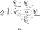
- the related interfaces of the network framework of the above network based Identifier and Locator separation framework are shown in FIG. 2 .
- the S1/D1 is the interface between the user terminal and the AGR
- S1 is used for the signaling of the user access management
- the D1 is the data forwarding interface.
- S2 is used for the handover management signaling during the handover between the AGRs
- the D2 is for data forwarding during the handover between the AGRs.
- D3 is a data forwarding interface between the AGR and the GSR
- the S4/S5/S6 are the signaling interfaces used for inquiring and maintaining the AID-RID mapping relationship.
- D4m is a data forwarding interface between the AGR and IDMS. when there is no direct coupling relationship between a visited IDMS and a home IDMS, the Broke IDMS forwards the signaling between the visited IDMS and the home IDMS.
- the method of handover management realizing mobility support in the above-mentioned network framework is described hereinafter.
- the CN and the MN establish communication, receive and transmit the data message with each other.
- the AGR where the CN is located can query the mapping relationship between the AID and the RID of the MN from the mapping server IDMS according to the AID carried in the message of the MN, thus obtaining the route location identifier RID of the MN.
- the handover flow is triggered.
- the handover-out gateway AGR and the handover-in gateway AGR establish the forwarding relationship, and in the handover process or after the handover finishes, the handover-out gateway AGR forwards the received data message transmitted towards the MN to the handover-in gateway AGR, and the handover-in gateway AGR forwards to the MN.
- the AID-RID mapping relationship of the MN stored in the mapping server IDMS is updated, and the CN is notified of the new AID-RID mapping relationship, and other associated constituent parts are notified in the network.
- the specific flow is as shown in FIG. 3 and includes the following steps.
- the source RAN when determining that the MN needs to perform the handover, transmits a handover request carrying the identifier information, such as AIDm and so on, of the target RAN and the MN to the handover-out gateway AGR1.
- the source RAN can perform the handover judgment combining with the distribution situation of the radio resource according to the information, such as strong or weak wireless signal of the MN, system load, etc.
- the source RAN is the radio access network that the MN accesses currently, and the handover-out gateway is the access gateway router that the MN connects currently.
- the AGR1 After receiving the handover request message transmitted by the radio access system, finds the handover-in AGR2 according to the identifier information of the target RAN and forwards the handover request message to the AGR2, and the message carries the identifier information of the MN.
- the corresponding relationship table of the adjacent RAN and AGR is configured in the AGR with the adjacent relationship in physical locations, and therefore, the AGR1 will store the corresponding relation table entry of the RAN and the AGR2.
- step 103 the AGR2, after receiving the handover request message, allocates a new RID for that user, establishes the AIDm-RIDm mapping relationship of that mobile node in the AGR2, and interacts messages with the target RAN to allocate the radio resource for the MN.
- step 104 the AGR2 transmits a handover response message to the AGR1, interacts the messages with the AGR1 to obtain the mapping relationship AIDc-RIDc of all CNs in data communication with the MN, and establishes the data forwarding relationship with the AGR1.
- the operation of establishing the data forwarding relationship here is the content of the related art, of which the typical practice is realized by way of tunnel encapsulation, that is, the AGR1, when receiving the data message transmitted by the MN from the AGR2, strips the tunnel encapsulation of the AGR1-AGR2, and then transmits to the CN; the AGR1, when receiving the data message transmitted towards the MN from the CN, adds the tunnel encapsulation of the AGR1-AGR2 in the header of the message and then transmits to the AGR2, and the AGR2 de-encapsulates and transmits to the MN.
- the AGR1 after recording the forwarding relationship with the AGR2, forwards the data message transmitted towards the MN, received during the handover, to the MN through the AGR2; in another example, the AGR1 can also cache the data message transmitted towards the MN first, and after the handover finishes, for example after receiving the handover completion message of the AGR2, then the AGR1 forwards the cached data message to the MN through the AGR2.
- the AGR1 after receiving the handover response, forwards the data directly to the AGR2 or forwards the data after caching.
- step 105 the AGR2 initiates a mapping update flow to the IDMS to update the AIDm-RIDm mapping relationship of that user terminal stored by the IDMS.
- step 104 can be performed with step 104 at the same time, and the precedence order of the two is not limited here.
- step 106 after receiving the handover response message transmitted by the AGR2, the AGR1 transmits the handover command to the MN through the source RAN.
- step 107 after receiving the handover command, the MN initiates the access request to the target RAN, requests to establish the communication link with the AGR2, and receives and transmits and receives the data message from the communication link.
- step after the MN receives the handover command, the communication contact with the source RAN/AGR1 is interrupted, and the MN needs to access the network from the target RAN side.
- step 108 AGR2, after receiving the handover completion message transmitted by the target RAN, forwards to the AGR1.
- step 109 the AGR2, according to the mapping relationship AIDc-RIDc of all CNs in the data communication with the MN obtained from the AGR1, initiates the mapping update relationship request to the access gateway router AGR3 directed by the RIDc, and notifies the access gateway router AGR3 of the CN to update the stored AIDm-RIDm mapping relationship of the MN.
- the AGR1 will delete the forwarding relationship between the AGR1 and the AGR2 of the MN, for example, during the handover, the AGR1 can set a message timer for forwarding the data to the AGR2, and the AGR1 will delete the forwarding relationship with the AGR2 after the timer is overtime; and/or the AGR2 transmits a signal for deleting the forwarding relationship to the AGR1 after finishing the process of updating the mapping relationship of the AGR3 of all CNs in communicating with the MN (the embodiment takes the case that the MN only has one correspondent node as an example for description), and the AGR1 deletes the forwarding relationship between the AGR1 and the AGR2 of the MN after receiving that signal.
- the handover management of the mobile node in the movement process mainly involves the interaction and processing among the mobile node, the access gateway router and the mapping server to guarantee that the communication between the user terminals which are initiating a communication or communicating in the handover process is performed normally, and meanwhile try to reduce the packet loss rate in the handover process.
- the access switch router AGRm needs to store the information of all CNs for each locally accessed MN, and notifies the new Identifier and Locator mapping relationship of the MN to the access switch router AGRc to which the CN belongs according to the stored information.
- the access switch router is required to have the following functions.
- mapping route table entry can be performed in the following ways.
- the access switch router AGRm decides which entry is to be replaced, and replaces it with a new mapping route entry. For example, the mapping route entry not being queried in the maximum duration is replaced, the entry with a minimum number of the querying times is replaced, or the entry with a lower preferential rank is replaced, etc.
- the network framework which the present example is based on can be a locator/ID separation protocol (LISP) + alternative logical topology (ALT), wherein, the egress tunnel router (ETR) / ingress tunnel router (ITR) are corresponding to the AGR (that is, the AGR is equal to the function combination of the ETR and ITR) in example one and the mapping distribution node (map-resolver) / mapping server (map-server) are responding to the IDMS in example 1.
- the endpoint identifiers (EID) in the LISP are corresponding to the AID in example 1
- the route address (routing locators, RLOC) is corresponding to the RID in example 1.
- the specific implementation steps are totally the same as the example 1.
- the tunnel routers are introduced in the LISP system, and the terminal encapsulates the LISP when transmitting the data packet and the data packet is de-encapsulated before arriving to the destination.
- the ITR encapsulates a new LISP header for each packet and the new header is stripped in the ETR. That operation process is corresponding to that in example one, the AGR transmits the data message of the terminal in backbone network after encapsulating Identifier in the data message, and when receiving the data message transmitted towards the terminal, the AGR de-encapsulates and then transmits to the terminal after receiving the data message transmitted to the terminal.
- the IP addresses of "the external layer header" in the LISP data packet are RLOCs.
- the ITR performs the EID-to-RLOC searching to determine the route path to the ETR, and the ETR takes the RLOC as its one address. That operation is corresponding to that in Example one, the AGR encapsulates the RID route information in the data message transmitted by the terminal, and then the data message is routing forwarded to the AGR where the correspondent node directed by the destination RID is located through the GSR.
- the ALT as one topological structure in the Internet, is identified as a plane with special functions by the way defined by the LISP system, which is equal to the IDMS in the backbone network in Example one.
- the network framework which the present example is based on can be an integration network, as shown in FIG. 5 , wherein, the access router is corresponding to the AGR in Example one.
- the specific implementation steps of the present example are the same as the Example one, which will not go into details here.
- the present invention further provides a system for handover management of a mobile node, applied to an Identifier and Locator separation framework including a MN, a RAN and an AGR, wherein, the AGR further includes a route location identifier allocating module, a correspondent node information obtaining module and a mapping relationship updating module, wherein:
- the AGR further comprises a route location identifier allocating module, a correspondent node information obtaining module and a mapping relationship updating module, wherein, the route location identifier allocating module is configured to, after receiving the handover request of the MN, allocate a new route location identifier (RID) for the MN and transmit to the mapping relationship updating module; the correspondent node information obtaining module is configured to, after receiving the handover request, obtain information of all CNs in communication with the MN from the AGR of the source RAN of the MN and transmit to the mapping relationship updating module; after receiving the request for obtaining information of the correspondent node transmitted by the AGR of the target RAN which the MN hands over to, transmit the information of all CNs in communication with the MN to the AGR of the target RAN; the mapping relationship updating module is configured to, after receiving the new RID of the MN, establish a new Identifier and Locator mapping relationship of the MN, and notify the AGR where the CN is located the new Identifier and Locator mapping
- mapping relationship updating module of the AGR2 is further configured to, after establishing the new Identifier and Locator mapping relationship of the MN, initiate a mapping update request to a mapping server to request to update the Identifier and Locator mapping relationship of the MN.
- the AGR further comprises a data forwarding module, wherein, the data forwarding module of the AGR of the target RAN is configured to, after receiving the handover request, establish a forwarding relationship with the AGR of the source RAN, and transmit a data message transmitted towards the MN to the MN after receiving the handover completion message; the data forwarding module of the AGR of the source RAN is configured to, according to the established forwarding relationship, transmit the received data message transmitted towards the MN to the AGR of the target RAN during the handover or after receiving the handover completion message.
- mapping relationship updating module of the AGR of the target RAN is further configured to, after notifying the new Identifier and Locator mapping relationship of the MN to the AGR where the CN is located, transmit a deleting instruction to the AGR of the source RAN; the mapping relationship updating module of the AGR of the source RAN is further configured to, delete the forwarding relationship according to the deleting instruction, and/or, delete the forwarding relationship in a certain time after establishing the forwarding relationship.
- the AGR further comprises a timing module and an entry managing module, wherein, the timing module is configured to set a time cycle of the polling timer, and notify the entry managing module when the time cycle of the polling timer arrives; the entry managing module is configured to store the Identifier and Locator mapping route table of all CNs in communication with the MN, set a timer label for each entry when establishing the entries of the mapping route table, and an initialization value of the timer label is a set default integer value; when querying a certain entry of the mapping route table every time, reset the timer label corresponding to the entry of the mapping route table to the initialization value; and when receiving the notification of the timing module, poll the entries of the mapping route table, reduce the timer label corresponding to each entry of the mapping route table by 1, and then delete a certain entry of the mapping route table when detecting that the timer label of the entry of the mapping route table is 0.
- the example of the present invention also provides an AGR implementing user data management in a handover process of a
- mapping relationship updating module is further configured to, after establishing the new Identifier and Locator mapping relationship of the MN, initiate a mapping update request to a mapping server to request to update the Identifier and Locator mapping relationship of the MN.
- the AGR further comprises a data forwarding module, wherein, the data forwarding module of the AGR2 is configured to, after receiving the handover request, establish a forwarding relationship with the AGR1, and transmit a data message transmitted towards the MN to the MN after receiving the handover completion message; the data forwarding module of the AGR1 is configured to, according to the established forwarding relationship, transmit the received data message transmitted towards the MN to the AGR2 during the handover or after receiving the handover completion message.
- mapping relationship updating module of the AGR of the target RAN is further configured to, after notifying the AGR where the CN is located of the new Identifier and Locator mapping relationship of the MN, transmit a deleting instruction to the AGR of the source RAN; the mapping relationship updating module of the AGR of the source RAN is further configured to, delete the forwarding relationship according to the deleting instruction, and/or, delete the forwarding relationship in a certain time after establishing the forwarding relationship.
- the AGR further comprises a timing module and an entry managing module, wherein, the timing module is configured to set a time cycle of a polling timer, and notify the entry managing module when the time cycle of the polling timer arrives; the entry managing module is configured to store the Identifier and Locator mapping route table of all CNs in communication with the MN, set a timer label for each entry when establishing the entries of the mapping route table, wherein, an initialization value of the timer label is a set default integer value; when querying a certain entry of the mapping route table every time, reset the timer label corresponding to the entry of the mapping route table to the initialization value; and when receiving the notification of the timing module, poll the entries of the mapping route table, reduce the timer label corresponding to each entry of the mapping route table by 1, and delete a certain entry of the mapping route table when detecting that the timer label of the entry of the mapping route table is 0.
- the timing module is configured to set a time cycle of a polling timer, and notify the entry managing module when
- the scheme in the present invention realizes the handover management of the mobility in the Identifier and Locator separation framework based on the network, provides a simple handover management procedure by combining the characteristic of the mobile communication network, provides an optimized user data management method in the handover management procedure, and makes the function distribution and the main procedure of each function entity in the handover management procedure clearly.
- a method for compatible transition is provided for the current mobile communication cell network, and the related procedure of mobility management in the network based Identifier and Locator separation framework is implemented by network side equipments, and there is no new function requirement for the mobile node and the mobile node can support without changing.
Landscapes
- Engineering & Computer Science (AREA)
- Computer Networks & Wireless Communication (AREA)
- Signal Processing (AREA)
- Mobile Radio Communication Systems (AREA)
Description
- This invention relates to the field of communication technology, and in particular, to a method, system and access gateway router (AGR) for handover management of a mobile node and user data management during the handover.
- The IP address in the transmission control protocol/internet protocol (TCP/IP) used extensively in existing Internet has double functions, not only regarded as the Locator of the communication terminal host network interface of the network layer in network topology, but also regarded as the Identifier of the host network interface of the transmission layer. The situation when the host moves has not been considered at the beginning of designing the TCP/IP. However, when it is more and more general to move the host, the semantic overload defect of this kind of IP address is obvious day by day. When the IP address of the host changes, not only the routing changes, but the Identifier of the communication terminal host also changes, thus causing the routing load more and more serious, and the changing of the host identifier also will cause the interruption of application and connection.
- The problem of the Identifier and Locator separation is proposed to aim at solving the problems including the semantic over load and the serious routing load of the IP address, etc., separating the double function of the IP address, realizing supporting to the problems, such as, the mobility, multiple home-ness, dynamic re-allocation of the IP address, reduction of the routing load and the exchange visit between different network areas in next generation Internet.
- In the prior art, the implement method based on the network router is one of the solutions about the Identifier and Locator separation. The prior art has proposed an implement method of mobile handover management based on the network router scheme, where the access switch router is used to notify all the access switch routers where the Correspondent Nodes (CNs) of the mobile nodes are located of the new mapping relationship of the mobile node (MN for short).
- All CN information for each locally accessed MN is stored in the access switch router, which informs, according to the stored information, the access switch router where the CN is located of the new identifier mapping relationship of the MN. The number of the records of the CNs stored by the access switch router is limited and every record needs one deleting timer, to save the memory space.
- In a specific embodiment, it is firstly required that the access switch router can store the records of the CNs of all the locally accessed user terminals, and secondly there is a requirement that all the access switch routers can notify the access router which the correspondent node accesses independently or with the help of the mapping server. If the mapping server cannot provide the help of forwarding the notification, then the access switch router must store the information of the access switch router where the correspondent node is located. Table 1 and table 2 are a kind of organizing mode of the locally accessed mapping table and the correspondent node mapping table stored by the access switch router in this case.
Table 1, Identifier mapping table of the locally accessed terminal of the access switch router Access identifier Router identifier Correspondent node 1 ... Correspondent node N - In table 1, the maximum number of records of the correspondent node must be limited, or else the pressure of the memory is too large.
Table 2, Mapping identifier mapping table of the correspondent node of the access switch router Access identifier Router identifier Access switch router of the access network Timer - In table 2, the record (including the access identifier and routing identifier) of every correspondent node may also require a timer, to determine that the record of a correspondent node should be deleted if there is no communication with this correspondent node for a long time to save the memory space.
- The above solution mainly has the following problems:
- 1. there is a memory consuming to set the timer, and the way to set a deleting timer for each record reduces the number of records of correspondent nodes able to be stored, and can not save the memory space;
- 2. there is a certain consuming of the processing performance of the central processing unit (CPU) to set the timer, and the way to set a deleting timer for each record to limit the number of records of correspondent nodes stored by the access switch router, makes the number of the timers that the access switch router can support at the same time also become one of the limitation conditions.
- In addition, the Chinese patent
CN 101119312A discloses a solution for the Identifier and Locator separation. In that solution, the mobility detection of the mobile node mainly is mainly completed relying on the message interaction between the user terminal and the access switch router. The access router needs to periodically transmit the router notification, and the user terminal, relying on that router notification or link state event of the lower layer communication link to find its own movement. The user terminal, after finding its own movement, should apply for re-access to the access router, which helps to complete the authentication and assigning new terminal Locator. Then the access router further takes charge of notifying the mapping server to update the mapping relationship of the user terminal. In order to shorten the handover time correspondingly, the user terminal can broadcast a router notification request after re-establishing the link, then the access switch router replies with a router notification message including the access port identifier of the access switch router, and the user terminal then modifies the gateway and initiates the access request. - In the above-mentioned solution, the process of mobility detection of the user terminal is finished mainly by the cooperation of the user terminal with the access switch router. Under the scenario of handover, the landmark trigger condition of initiating a handover management flow is that the user terminal finds its own movement and applies for re-accessing to the access router. In the case of networking of cell mobile network, compared with the base station system, such as the base station subsystem (BSS), radio access network (RAN), evolved node B (eNodeB), etc., the user terminal does not know the radio resource distribution situation of the wireless network, and cannot finish the selection of the handover target cell. Also, there will be a greater handover time delay if the terminal initiates the handover. In addition, the mobility detection needs to be finished by the cooperation of the user terminal, and the protocol stack software of the user terminal needs to be modified, facing the obstacle of the synchronous updating of the user desktop software.
- The features of the preamble of the independent claims are known from
CN 101 119 312 A . Related technologies are known fromWO 2009/106615 A1 . DocumentsEP 2 480 011 A1 ,EP 2 480 033 A1 andEP 2 482 585 A1 , published after the filing date of the present application, disclose another examples of the prior art. - The technical problem to be solved in the invention is to provide a method and system for handover management of a mobile node, which realizes the handover management of the mobility in an Identifier and Locator separation framework. The present invention is defined in the independent claims.
- A method for handover management of a mobile node is provided, applied to an Identifier and Locator separation framework, wherein, when a current source radio access network (RAN) of a mobile node (MN) determines that the MN needs to initiate a handover, the method comprises:
- the source RAN initiating a handover request comprising information of a target RAN to a first access gateway router (AGR1), and the AGR1 transmitting the handover request to a second access gateway router (AGR2) of the target RAN according to the information of the target RAN;
- the AGR2, after receiving the handover request, returning a handover response; after receiving the handover response, the AGR1 transmitting a handover command to the MN; and
- the MN initiating an access request to the target RAN according to the received handover command and finishing the handover to the target RAN.
- The method further comprises:
- the AGR2, after receiving the handover request, allocating a new route location identifier (RID) for the MN, establishing a new Identifier and Locator mapping relationship of the MN; and obtaining information of all correspondent nodes (CNs) in communication with the MN from the AGR1; and
- after receiving a handover completion message transmitted by the target RAN, the AGR2 notifying the AGR where the CN is located of the new Identifier and Locator mapping relationship of the MN according to the obtained information of the CN.
- The method further comprises:
the AGR2, after establishing the new Identifier and Locator mapping relationship of the MN, initiating a mapping update request to a mapping server to request to update the Identifier and Locator mapping relationship of the MN. - The method further comprises:
- the AGR2, after receiving the handover request, establishing a forwarding relationship with the AGR1; and
- the AGR1 transmitting a received data message transmitted towards the MN to the AGR2 during the handover or after receiving the handover completion message, and the AGR2 forwarding the data message to the MN.
- The method further comprises:
in the step of the AGR2 establishing the forwarding relationship with the AGR1, the AGR2 and the AGR1 establishes the forwarding relationship by the way of tunnel capsulation, to forward the data message. - The method further comprises:
the AGR1 deleting the forwarding relationship in a certain time after establishing the forwarding relationship, and/or, the AGR2, after notifying the AGR where the CN is located of the new Identifier and Locator mapping relationship of the MN , transmitting a deleting instruction to the AGR1, and the AGR1 deleting the forwarding relationship according to the deleting instruction. - The AGR stores an Identifier and Locator mapping route table of all the CNs in communication with the MN, and performs an aging process to the mapping route table by the following way:
- setting a polling timer;
- when establishing entries of the mapping route table, setting a timer label for each entry, and an initialization value of the timer label being a set default integer value;
- when querying a certain entry of the mapping route table every time, resetting the timer label corresponding to the entry of the mapping route table to the initialization value;
- when a time cycle of the polling timer arrives, polling the mapping route table, reducing the timer label corresponding to each entry of the mapping route table in the mapping route table by 1, and deleting a certain entry of the mapping route table when detecting that the timer label of the entry of the mapping route table is 0.
- A method for handover management of a mobile node is further provided, applied to an Identifier and Locator separation framework, wherein, when a current source radio access network (RAN) of a mobile node (MN) determines that the MN needs to initiate a handover, the method comprises:
- the source RAN initiating a handover request including information of a target RAN to a first access gateway router (AGR1), and the AGR1 transmitting the handover request to a second access gateway router (AGR2) of the target RAN according to the information of the target RAN;
- the AGR2, after receiving the handover request, allocating a new route location identifier (RID) for the MN, establishing a new Identifier and Locator mapping relationship of the MN; and obtaining information of all correspondent nodes (CNs) in communication with the MN from the AGR1;
- the MN initiating an access request to the target RAN and finishing the handover to the target RAN; after receiving a handover completion message transmitted by the target RAN, the AGR2 notifying the AGR where the CN is located of the new Identifier and Locator mapping relationship of the MN according to the obtained information of the CN.
- The method further comprises:
the AGR2, after establishing the new Identifier and Locator mapping relationship of the MN, initiating a mapping update request to a mapping server to request to update the Identifier and Locator mapping relationship of the MN. - The method further comprises:
- the AGR2, after receiving the handover request, establishing a forwarding relationship with the AGR1; and
- the AGR1 transmitting a received data message transmitted towards the MN to the AGR2 during the handover or after receiving the handover completion message, and the AGR2 forwarding to the MN.
- A method of user data management of an access gateway router in a handover process of a mobile node is further provided, applied to an Identifier and Locator separation framework, wherein, when the MN hands over from a source radio access network (RAN) to a target RAN, the method comprising:
- a second access gateway router (AGR2) of the target RAN allocating new route location identifier (RID) for the MN, establishing a new Identifier and Locator mapping relationship of the MN; and obtaining information of all CNs in communication with the MN from a first access gateway router (AGR1) of the source RAN; and
- after the MN completes the handover, the AGR2 notifying the AGR where the CN is located of the new Identifier and Locator mapping relationship of the MN according to the obtained information of the CN.
- The method further comprises:
the AGR2, after establishing a new Identifier and Locator mapping relationship of the MN, initiating a mapping update request to a mapping server to request to update the Identifier and Locator mapping relationship of the MN. - The method further comprises:
- the AGR2, after receiving the handover request, establishing a forwarding relationship with the AGR1; and
- the AGR1 transmitting a received data message transmitted towards the MN to the AGR2 during the handover or after receiving the handover completion message, and the AGR2 forwarding to the MN.
- The method further comprises:
the AGR1 deleting the forwarding relationship in a certain time after establishing the forwarding relationship, and/or, the AGR2, after notifying the AGR where the CN is located of the new Identifier and Locator mapping relationship of the MN, transmitting a deleting instruction to the AGR1, and the AGR1 deleting the forwarding relationship according to the deleting instruction. - The AGR where the MN is located stores an Identifier and Locator mapping route table of all CNs in communication with the MN, and performs an aging processing on the mapping route table by the following way:
- setting a polling timer;
- when establishing entries of the mapping route table, setting a timer label for each entry, and an initialization value of the timer label being a set default integer value;
- when querying a certain entry of the mapping route table every time, resetting the timer label corresponding to the entry of the mapping route table to the initialization value;
- when a time cycle of the polling timer arrives, polling the mapping route table, reducing the timer label corresponding to each entry of the mapping route table in the mapping route table by 1, and deleting a certain entry of the mapping route table when detecting that the timer label of the entry of the mapping route table is 0.
- A system for handover management of a mobile node is further provided, applied to an Identifier and Locator separation framework, wherein, the system comprising a mobile node (MN), a radio access network (RAN) and an access gateway router (AGR), wherein:
- a current source RAN of the MN is configured to, when determining that the MN needs to initiate a handover, initiate a handover request comprising information of a target RAN to a first access gateway router (AGR1);
- the AGR1 is configured to transmit the handover request to a second access gateway router (AGR2) of the target RAN according to the information of the target RAN in the received handover request;
- the AGR2 is configured to, after receiving the handover request, return a handover response;
- the target RAN is configured to complete the access of the MN according to the received access request, and transmit a handover completion message to the AGR2;
- the MN is configured to, according to the received handover command, initiate the access request to the target RAN through the AGR2, and finish the handover to the target RAN.
- The AGR comprises a route location identifier allocating module, a correspondent node information obtaining module and a mapping relationship updating module, wherein,
the route location identifier allocating module is configured to, after receiving the handover request of the MN, allocate a new route location identifier (RID) for the MN and transmit to the mapping relationship updating module;
the correspondent node information obtaining module is configured to, after receiving the handover request, obtain information of all CNs in communication with the MN from the AGR of the source RAN of the MN and transmit to the mapping relationship updating module; after receiving the request for obtaining information of the correspondent node transmitted by the AGR of the target RAN which the MN hands over to, transmit the information of all CNs in communication with the MN to the AGR of the target RAN;
the mapping relationship updating module is configured to, after receiving the new RID of the MN, establish a new Identifier and Locator mapping relationship of the MN, and notify the AGR where the CN is located the new Identifier and Locator mapping relationship of the MN according to the information of the CN. - The mapping relationship updating module of the AGR2 is further configured to, after establishing the new Identifier and Locator mapping relationship of the MN, initiate a mapping update request to a mapping server to request to update the Identifier and Locator mapping relationship of the MN.
- The AGR further comprises a data forwarding module, wherein,
the data forwarding module of the AGR of the target RAN is configured to, after receiving the handover request, establish a forwarding relationship with the AGR of the source RAN, and transmit a data message transmitted towards the MN to the MN after receiving the handover completion message;
the data forwarding module of the AGR of the source RAN is configured to, according to the established forwarding relationship, transmit the received data message transmitted towards the MN to the AGR of the target RAN during the handover or after receiving the handover completion message. - The mapping relationship updating module of the AGR of the target RAN is further configured to, after notifying the new Identifier and Locator mapping relationship of the MN to the AGR where the CN is located, transmit a deleting instruction to the AGR of the source RAN;
the mapping relationship updating module of the AGR of the source RAN is further configured to, delete the forwarding relationship according to the deleting instruction, and/or, delete the forwarding relationship in a certain time after establishing the forwarding relationship. - The AGR further comprises a timing module and an entry managing module, wherein,
the timing module is configured to set a time cycle of the polling timer, and notify the entry managing module when the time cycle of the polling timer arrives;
the entry managing module is configured to store the Identifier and Locator mapping route table of all CNs in communication with the MN, set a timer label for each entry when establishing the entries of the mapping route table, and an initialization value of the timer label is a set default integer value; when querying a certain entry of the mapping route table every time, reset the timer label corresponding to the entry of the mapping route table to the initialization value; and when receiving the notification of the timing module, poll the entries of the mapping route table, reduce the timer label corresponding to each entry of the mapping route table by 1, and then delete a certain entry of the mapping route table when detecting that the timer label of the entry of the mapping route table is 0. - An access gateway router of user data management in a handover process of a mobile node is further provided, applied to an Identifier and Locator separation framework, comprising a route location identifier allocating module, a correspondent node information obtaining module and a mapping relationship updating module, wherein,
the route location identifier allocating module is configured to, after receiving a handover request of the mobile node (MN), allocate a new route location identifier (RID) to the MN and transmit the new RID to the mapping relationship updating module;
the correspondent node information obtaining module is configured to, after receiving the handover request, obtain information of all correspondent nodes (CNs) in communication with the MN from an access gateway router (AGR) of a source radio access network (RAN) of the MN and transmit to the mapping relationship updating module; after receiving the request for obtaining information of the correspondent node transmitted by the AGR of the target RAN which the MN hands over to, transmit the information of all the CNs in communication with the MN to the AGR of the target RAN;
the mapping relationship updating module is configured to, after receiving the new RID of the MN, establish a new Identifier and Locator mapping relationship of the MN, and notify the AGR where the CN is located of the new Identifier and Locator mapping relationship of the MN according to the information of the CN. - The mapping relationship updating module is further configured to, after establishing the new Identifier and Locator mapping relationship of the MN, initiate a mapping update request to a mapping server to request to update the Identifier and Locator mapping relationship of the MN.
- The AGR further comprises a data forwarding module, wherein,
the data forwarding module of the AGR2 is configured to, after receiving the handover request, establish a forwarding relationship with the AGR1, and transmit a data message transmitted towards the MN to the MN after receiving the handover completion message;
the data forwarding module of the AGR1 is configured to, according to the established forwarding relationship, transmit the received data message transmitted towards the MN to the AGR2 during the handover or after receiving the handover completion message. - The mapping relationship updating module of the AGR of the target RAN is further configured to, after notifying the AGR where the CN is located of the new Identifier and Locator mapping relationship of the MN, transmit a deleting instruction to the AGR of the source RAN;
the mapping relationship updating module of the AGR of the source RAN is further configured to, delete the forwarding relationship according to the deleting instruction, and/or, delete the forwarding relationship in a certain time after establishing the forwarding relationship. - The AGR further comprises a timing module and an entry managing module, wherein,
the timing module is configured to set a time cycle of a polling timer, and notify the entry managing module when the time cycle of the polling timer arrives;
the entry managing module is configured to store the Identifier and Locator mapping route table of all CNs in communication with the MN, set a timer label for each entry when establishing the entries of the mapping route table, wherein, an initialization value of the timer label is a set default integer value; when querying a certain entry of the mapping route table every time, reset the timer label corresponding to the entry of the mapping route table to the initialization value; and when receiving the notification of the timing module, poll the entries of the mapping route table, reduce the timer label corresponding to each entry of the mapping route table by 1, and delete a certain entry of the mapping route table when detecting that the timer label of the entry of the mapping route table is 0. - Compared with the related art, the above solution has at least the following advantages.
- The solution realizes the handover management of the mobility in the Identifier and Locator separation framework based on the network, provides a simple handover management procedure by combining the characteristic of the mobile communication network, provides an optimized user data management method in the handover management procedure, and makes the function distribution and the main procedure of each function entity in the handover management procedure clearly.
- A method for compatible transition is provided based on the mobile communication cell network, such as the wideband code division multiple access (WCDMA), the code division multiple access (CDMA), the time division-synchronous code division multiple access (TDSCDMA), the high speed downlink packet access (HSDPA), the high speed uplink packet access (HSUPA), the long term evolution (LTE), the worldwide interoperability for microwave access (WiMax), etc., and the related procedure of mobility management in the network based Identifier and Locator separation framework is implemented by network side equipments, and there is no new function requirement for the mobile node and the mobile node can support without changing.
-
-
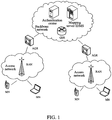
FIG. 1 is a schematic diagram of the network topology of a network based Identifier and Locator separation framework according to Example one of the present invention. -
FIG. 2 is a schematic diagram of related interfaces of the network framework of the network based Identifier and Locator separation framework according to Example one of the present invention. -
FIG. 3 is a flow chart of a method of handover management in an Identifier and Locator separation framework according to Example one of the present invention. -
FIG. 4 is a schematic diagram of the network topology of an Identifier and Locator separation framework based on LISP protocol according to Example two of the present invention. -
FIG. 5 is a schematic diagram of the network topology of an Identifier and Locator separation framework of an integration network according to Example three of the present invention. - The present invention is described in detail with reference to the accompanying drawings and in combination with examples hereinafter.
- In order to overcome the disadvantage of the related art, the present example provides a network based Identifier and Locator separation framework, of which the core idea is to divide the network into an access layer and a core layer, and there are two kinds of identifier types of the mobile nodes in the network: a user identifier (access identifier, AID for short) and routing location identifier (RID for short). A unique AID is configured for each user in the network, and that AID maintains unchanged all the time in the movement process; while in the data forwarding process, the AID can only be used in the access layer, and the RID can only be used in the core layer; when communicating in the application layer between the user terminals, the AID is used to identify the opposite end.
- The schematic diagram of the topology of the above network based Identifier and Locator separation framework is as shown in
FIG.1 , wherein, the network based Identifier and Locator separation framework mainly includes: a radio access network (RAN), an access gateway router (AGR for short), a general switch router (GSR for short), a mapping server (identifier mapping server, IDMS for short), an authentication center, etc. Those are described separately as follows. - The AGR is responsible for providing access service for various mobile nodes, allocating the RID for the accessed user, and transmitting the user data message in the backbone network after encapsulating the identifier into the data message.
- The AGR, when receiving the data message transmitted by the terminal, queries the AID-RID mapping table in the local cache (CACHE) according to the destination address (that is the AID of the correspondent node) in the data message. Specifically, if the corresponding AID-RID mapping entry is queried out, then the AGR encapsulates the RID of the found communication terminal in the header of the message and transmits to the backbone network to perform the forwarding processing; if the corresponding AID-RID mapping entry is not queried out, the AGR forwards the data message to the backbone network, and initiates the process of querying the AID-RID mapping information (of the correspondent node) to the IDMS, and stores the corresponding AIDc-RIDc mapping returned by the IDMS locally to be ready for querying when forwarding the message subsequently.
- Or, the AGR, when having not queried out the corresponding AID-RID mapping entry, can also select not to forward the data message to the backbone network but to initiate the process of querying the AID-RID mapping information (of the correspondent node) to the IDMS, and encapsulates the found RID of the correspondent node in the header of the message and transmits to the backbone network to perform the forwarding processing after the IDMS returns the corresponding AIDc-RIDc mapping.
- The AGR, when receiving the data message transmitted to the terminal, performs the de-encapsulation processing to the data message, strips the newly added header of the message including the RID in the data message, and transmits to the terminal.
- The main functions of the GSR are to perform the route selection and forward the data message according to the routing location identifier (RID) in the data message.
- The IDMS is mainly responsible for maintaining the mapping relationship of the access identifier and location identifier in the network, and providing the querying service to the access gateway router and other mapping servers.
- The authentication center is responsible for recording the information such as the user type, user service grade, etc., and performing validity authentication and authorization to the user when the user accesses. The authentication center supports the two-way authentication between the network and the user.
- The radio access network is responsible for providing and maintaining the two-layer link from the user terminal to the AGR; and responsible for wireless resource management in the case of the cell mobile network application scene.
- In that framework shown in
FIG. 1 , the network can be divided into an access network and a backbone network. The access network locates at the edge of backbone network, responsible for the accessing of all terminals, and in the RAN section, all the user terminals use AID to address. The backbone network is responsible for the routing of the terminals accessing through different access networks. The access network and the backbone network do not overlap on the topological relationship. AID is used in the application layer between the communication hosts to identify the opposite end, and the communication between the user terminals can perform with the only need of using the AID of the opposite end. - The access gateway router locates at the boundary point of the backbone network and the access network, interfacing with the access network and the backbone network, responsible for providing the access service for the terminal, maintaining the user connection, forwarding the user data, etc. All the communications between user terminals are forwarded and managed through the access gateway router in the located access network. The data message between the terminals in the service range of the same access gateway router is forwarded to the opposite end directly. The data message between the terminals locating at service ranges of different access gateway routers is forwarded as follows: when the terminal sends out the data message, the corresponding access gateway router carries the RID information (that RID is corresponding to the AID) in the forwarded data message; correspondingly, when the terminal receives the data message, the access gateway router performs the opposite operation, that is, strips the RID information and forwards the data message to the terminal. The mapping server stores the mapping relationship between Identifier and Locator allocated to all accessed user terminals in the network, and analyzes the identifier relationship through the signaling interacting with the access gateway router.
- The related interfaces of the network framework of the above network based Identifier and Locator separation framework are shown in
FIG. 2 . The S1/D1 is the interface between the user terminal and the AGR, S1 is used for the signaling of the user access management, and the D1 is the data forwarding interface. S2 is used for the handover management signaling during the handover between the AGRs, and the D2 is for data forwarding during the handover between the AGRs. D3 is a data forwarding interface between the AGR and the GSR, and the S4/S5/S6 are the signaling interfaces used for inquiring and maintaining the AID-RID mapping relationship. D4m is a data forwarding interface between the AGR and IDMS. when there is no direct coupling relationship between a visited IDMS and a home IDMS, the Broke IDMS forwards the signaling between the visited IDMS and the home IDMS. - The method of handover management realizing mobility support in the above-mentioned network framework is described hereinafter. The CN and the MN establish communication, receive and transmit the data message with each other. In the process of establishing the communication relationship with MN, the AGR where the CN is located can query the mapping relationship between the AID and the RID of the MN from the mapping server IDMS according to the AID carried in the message of the MN, thus obtaining the route location identifier RID of the MN.
- After the radio access network detects the mobility of the MN (that is, the location of the MN has changed, moving from the coverage of one AGR to another AGR, and in this case, it needs to initiate a handover flow), the handover flow is triggered. In the handover process, the handover-out gateway AGR and the handover-in gateway AGR establish the forwarding relationship, and in the handover process or after the handover finishes, the handover-out gateway AGR forwards the received data message transmitted towards the MN to the handover-in gateway AGR, and the handover-in gateway AGR forwards to the MN.
- The AID-RID mapping relationship of the MN stored in the mapping server IDMS is updated, and the CN is notified of the new AID-RID mapping relationship, and other associated constituent parts are notified in the network.
- The specific flow is as shown in
FIG. 3 and includes the following steps. - In
step 101, the source RAN, when determining that the MN needs to perform the handover, transmits a handover request carrying the identifier information, such as AIDm and so on, of the target RAN and the MN to the handover-out gateway AGR1. - The source RAN can perform the handover judgment combining with the distribution situation of the radio resource according to the information, such as strong or weak wireless signal of the MN, system load, etc. The source RAN is the radio access network that the MN accesses currently, and the handover-out gateway is the access gateway router that the MN connects currently.
- In step 102, the AGR1, after receiving the handover request message transmitted by the radio access system, finds the handover-in AGR2 according to the identifier information of the target RAN and forwards the handover request message to the AGR2, and the message carries the identifier information of the MN.
- In the cell mobile network, the corresponding relationship table of the adjacent RAN and AGR is configured in the AGR with the adjacent relationship in physical locations, and therefore, the AGR1 will store the corresponding relation table entry of the RAN and the AGR2.
- In step 103, the AGR2, after receiving the handover request message, allocates a new RID for that user, establishes the AIDm-RIDm mapping relationship of that mobile node in the AGR2, and interacts messages with the target RAN to allocate the radio resource for the MN.
- In step 104, the AGR2 transmits a handover response message to the AGR1, interacts the messages with the AGR1 to obtain the mapping relationship AIDc-RIDc of all CNs in data communication with the MN, and establishes the data forwarding relationship with the AGR1.
- The operation of establishing the data forwarding relationship here is the content of the related art, of which the typical practice is realized by way of tunnel encapsulation, that is, the AGR1, when receiving the data message transmitted by the MN from the AGR2, strips the tunnel encapsulation of the AGR1-AGR2, and then transmits to the CN; the AGR1, when receiving the data message transmitted towards the MN from the CN, adds the tunnel encapsulation of the AGR1-AGR2 in the header of the message and then transmits to the AGR2, and the AGR2 de-encapsulates and transmits to the MN.
- The AGR1, after recording the forwarding relationship with the AGR2, forwards the data message transmitted towards the MN, received during the handover, to the MN through the AGR2; in another example, the AGR1 can also cache the data message transmitted towards the MN first, and after the handover finishes, for example after receiving the handover completion message of the AGR2, then the AGR1 forwards the cached data message to the MN through the AGR2.
- Certainly, the data forwarding relationship can also not be established. The AGR1, after receiving the handover response, forwards the data directly to the AGR2 or forwards the data after caching.
- In step 105, the AGR2 initiates a mapping update flow to the IDMS to update the AIDm-RIDm mapping relationship of that user terminal stored by the IDMS.
- The step can be performed with step 104 at the same time, and the precedence order of the two is not limited here.
- In
step 106, after receiving the handover response message transmitted by the AGR2, the AGR1 transmits the handover command to the MN through the source RAN. - In step 107, after receiving the handover command, the MN initiates the access request to the target RAN, requests to establish the communication link with the AGR2, and receives and transmits and receives the data message from the communication link.
- In that step, after the MN receives the handover command, the communication contact with the source RAN/AGR1 is interrupted, and the MN needs to access the network from the target RAN side.
- In step 108, AGR2, after receiving the handover completion message transmitted by the target RAN, forwards to the AGR1.
- In step 109, the AGR2, according to the mapping relationship AIDc-RIDc of all CNs in the data communication with the MN obtained from the AGR1, initiates the mapping update relationship request to the access gateway router AGR3 directed by the RIDc, and notifies the access gateway router AGR3 of the CN to update the stored AIDm-RIDm mapping relationship of the MN.
- The AGR3, after updating the AIDm-RIDm mapping relationship of the MN according to the received notification, transmits the data that the CN transmitted towards the MN to the AGR2. If the AGR2 does not receive the data packet transmitted by the AGR3 after initiating the update mapping relationship request to the AGR3, and still receives the data transmitted by the AGR1 constantly, it is illustrated that the AGR3 does not receive the update mapping relationship request, and then the AGR2 will re-initiate the update mapping relationship request to the AGR3.
- In addition, after the handover finishes, the AGR1 will delete the forwarding relationship between the AGR1 and the AGR2 of the MN, for example, during the handover, the AGR1 can set a message timer for forwarding the data to the AGR2, and the AGR1 will delete the forwarding relationship with the AGR2 after the timer is overtime; and/or the AGR2 transmits a signal for deleting the forwarding relationship to the AGR1 after finishing the process of updating the mapping relationship of the AGR3 of all CNs in communicating with the MN (the embodiment takes the case that the MN only has one correspondent node as an example for description), and the AGR1 deletes the forwarding relationship between the AGR1 and the AGR2 of the MN after receiving that signal.
- In the present invention, the handover management of the mobile node in the movement process mainly involves the interaction and processing among the mobile node, the access gateway router and the mapping server to guarantee that the communication between the user terminals which are initiating a communication or communicating in the handover process is performed normally, and meanwhile try to reduce the packet loss rate in the handover process.
- In the above-mentioned scheme, the access switch router AGRm needs to store the information of all CNs for each locally accessed MN, and notifies the new Identifier and Locator mapping relationship of the MN to the access switch router AGRc to which the CN belongs according to the stored information.
- Therefore, the access switch router is required to have the following functions.
- 1) The access switch router AGRm can store the records of all CNs communicating with the locally accessed user terminal MN.
- 2) The access switch router AGRm stores the Identifier and Locator mapping relationship of all CNs and forms the AIDc-RIDc mapping route table of the CN. The data message forwarded in the backbone network as shown in
FIG. 1 is generated by way of using the data message to encapsulate the RIDc header or by way of using the RIDc to replace the AIDc, through querying the AIDc-RIDc mapping route table. - 3) Due to the performance limitation of the access switch router AGRm, the mapping route table entries that can be stored are limited, and therefore, the AGRm needs to support the aging of the mapping route table entry.
- Further, the aging of the mapping route table entry can be performed in the following ways.
- The first way, when the mapping route table entry goes beyond the performance limitation of the access switch router AGRm, the access switch router AGRm decides which entry is to be replaced, and replaces it with a new mapping route entry. For example, the mapping route entry not being queried in the maximum duration is replaced, the entry with a minimum number of the querying times is replaced, or the entry with a lower preferential rank is replaced, etc.
- The second way, the following steps can be used.
- 1) The AGRm sets a uniform periodic timer Ti.
- 2) When the mapping route table entry is established, a timer label TL is stored for each entry, and the initialization TL is the a default integer value set by the AGRm system.
- 3) The AGRm resets the TL corresponding to a certain mapping route table entry to be the initialization value when querying that mapping route table entry every time.
- 4) When the Ti timer arrives, the AGRm polls the mapping route table entries, and reduces the TL corresponding to each mapping route table entry by 1. When the TL of a certain mapping route table entry is detected to be 0, the mapping route table entry is deleted.
- As shown in
FIG. 4 , the network framework which the present example is based on can be a locator/ID separation protocol (LISP) + alternative logical topology (ALT), wherein, the egress tunnel router (ETR) / ingress tunnel router (ITR) are corresponding to the AGR (that is, the AGR is equal to the function combination of the ETR and ITR) in example one and the mapping distribution node (map-resolver) / mapping server (map-server) are responding to the IDMS in example 1. Wherein, the endpoint identifiers (EID) in the LISP are corresponding to the AID in example 1, and the route address (routing locators, RLOC) is corresponding to the RID in example 1. The specific implementation steps are totally the same as the example 1. - The tunnel routers are introduced in the LISP system, and the terminal encapsulates the LISP when transmitting the data packet and the data packet is de-encapsulated before arriving to the destination. In the process of the end-to-end packet switching between the terminals in two networks, the ITR encapsulates a new LISP header for each packet and the new header is stripped in the ETR. That operation process is corresponding to that in example one, the AGR transmits the data message of the terminal in backbone network after encapsulating Identifier in the data message, and when receiving the data message transmitted towards the terminal, the AGR de-encapsulates and then transmits to the terminal after receiving the data message transmitted to the terminal.
- The IP addresses of "the external layer header" in the LISP data packet are RLOCs. The ITR performs the EID-to-RLOC searching to determine the route path to the ETR, and the ETR takes the RLOC as its one address. That operation is corresponding to that in Example one, the AGR encapsulates the RID route information in the data message transmitted by the terminal, and then the data message is routing forwarded to the AGR where the correspondent node directed by the destination RID is located through the GSR.
- The ALT, as one topological structure in the Internet, is identified as a plane with special functions by the way defined by the LISP system, which is equal to the IDMS in the backbone network in Example one.
- The specific implementation steps of the present example are same as the Example one, which will not go into details here.
- The network framework which the present example is based on can be an integration network, as shown in
FIG. 5 , wherein, the access router is corresponding to the AGR in Example one. The specific implementation steps of the present example are the same as the Example one, which will not go into details here. - Based on the above method, the present invention further provides a system for handover management of a mobile node, applied to an Identifier and Locator separation framework including a MN, a RAN and an AGR, wherein, the AGR further includes a route location identifier allocating module, a correspondent node information obtaining module and a mapping relationship updating module, wherein:
- a current source RAN of the MN is configured to, when determining that the MN needs to initiate a handover, initiate a handover request comprising information of a target RAN to a first access gateway router (AGR1);;
- the AGR1 is configured to transmit the handover request to a second access gateway router (AGR2) of the target RAN according to the information of the target RAN in the received handover request;
- the AGR2 is configured to, after receiving the handover request, return a handover response;
- the target RAN is configured to complete the access of the MN according to the received access request, and transmit a handover completion message to the AGR2;
- the MN is configured to, according to the received handover command, initiate the access request to the target RAN through the AGR2, and finish the handover to the target RAN.
- Wherein, the AGR further comprises a route location identifier allocating module, a correspondent node information obtaining module and a mapping relationship updating module, wherein,
the route location identifier allocating module is configured to, after receiving the handover request of the MN, allocate a new route location identifier (RID) for the MN and transmit to the mapping relationship updating module;
the correspondent node information obtaining module is configured to, after receiving the handover request, obtain information of all CNs in communication with the MN from the AGR of the source RAN of the MN and transmit to the mapping relationship updating module; after receiving the request for obtaining information of the correspondent node transmitted by the AGR of the target RAN which the MN hands over to, transmit the information of all CNs in communication with the MN to the AGR of the target RAN;
the mapping relationship updating module is configured to, after receiving the new RID of the MN, establish a new Identifier and Locator mapping relationship of the MN, and notify the AGR where the CN is located the new Identifier and Locator mapping relationship of the MN according to the information of the CN. - Wherein, the mapping relationship updating module of the AGR2 is further configured to, after establishing the new Identifier and Locator mapping relationship of the MN, initiate a mapping update request to a mapping server to request to update the Identifier and Locator mapping relationship of the MN.
- Wherein, the AGR further comprises a data forwarding module, wherein,
the data forwarding module of the AGR of the target RAN is configured to, after receiving the handover request, establish a forwarding relationship with the AGR of the source RAN, and transmit a data message transmitted towards the MN to the MN after receiving the handover completion message;
the data forwarding module of the AGR of the source RAN is configured to, according to the established forwarding relationship, transmit the received data message transmitted towards the MN to the AGR of the target RAN during the handover or after receiving the handover completion message. - Wherein, the mapping relationship updating module of the AGR of the target RAN is further configured to, after notifying the new Identifier and Locator mapping relationship of the MN to the AGR where the CN is located, transmit a deleting instruction to the AGR of the source RAN;
the mapping relationship updating module of the AGR of the source RAN is further configured to, delete the forwarding relationship according to the deleting instruction, and/or, delete the forwarding relationship in a certain time after establishing the forwarding relationship. - Wherein, the AGR further comprises a timing module and an entry managing module, wherein,
the timing module is configured to set a time cycle of the polling timer, and notify the entry managing module when the time cycle of the polling timer arrives;
the entry managing module is configured to store the Identifier and Locator mapping route table of all CNs in communication with the MN, set a timer label for each entry when establishing the entries of the mapping route table, and an initialization value of the timer label is a set default integer value; when querying a certain entry of the mapping route table every time, reset the timer label corresponding to the entry of the mapping route table to the initialization value; and when receiving the notification of the timing module, poll the entries of the mapping route table, reduce the timer label corresponding to each entry of the mapping route table by 1, and then delete a certain entry of the mapping route table when detecting that the timer label of the entry of the mapping route table is 0.In addition, the example of the present invention also provides an AGR implementing user data management in a handover process of a mobile node, applied to an Identifier and Locator separation framework including a route location identifier allocating module, a correspondent node information obtaining module and a mapping relationship updating module, wherein,
the route location identifier allocating module is configured to, after receiving a handover request of the mobile node (MN), allocate a new route location identifier (RID) to the MN and transmit the new RID to the mapping relationship updating module;
the correspondent node information obtaining module is configured to, after receiving the handover request, obtain information of all correspondent nodes (CNs) in communication with the MN from an access gateway router (AGR) of a source radio access network (RAN) of the MN and transmit to the mapping relationship updating module; after receiving the request for obtaining information of the correspondent node transmitted by the AGR of the target RAN which the MN hands over to, transmit the information of all the CNs in communication with the MN to the AGR of the target RAN;
the mapping relationship updating module is configured to, after receiving the new RID of the MN, establish a new Identifier and Locator mapping relationship of the MN, and notify the AGR where the CN is located of the new Identifier and Locator mapping relationship of the MN according to the information of the CN. - Wherein, the mapping relationship updating module is further configured to, after establishing the new Identifier and Locator mapping relationship of the MN, initiate a mapping update request to a mapping server to request to update the Identifier and Locator mapping relationship of the MN.
- Wherein, the AGR further comprises a data forwarding module, wherein,
the data forwarding module of the AGR2 is configured to, after receiving the handover request, establish a forwarding relationship with the AGR1, and transmit a data message transmitted towards the MN to the MN after receiving the handover completion message;
the data forwarding module of the AGR1 is configured to, according to the established forwarding relationship, transmit the received data message transmitted towards the MN to the AGR2 during the handover or after receiving the handover completion message. - Wherein, the mapping relationship updating module of the AGR of the target RAN is further configured to, after notifying the AGR where the CN is located of the new Identifier and Locator mapping relationship of the MN, transmit a deleting instruction to the AGR of the source RAN;
the mapping relationship updating module of the AGR of the source RAN is further configured to, delete the forwarding relationship according to the deleting instruction, and/or, delete the forwarding relationship in a certain time after establishing the forwarding relationship. - Wherein, the AGR further comprises a timing module and an entry managing module, wherein,
the timing module is configured to set a time cycle of a polling timer, and notify the entry managing module when the time cycle of the polling timer arrives;
the entry managing module is configured to store the Identifier and Locator mapping route table of all CNs in communication with the MN, set a timer label for each entry when establishing the entries of the mapping route table, wherein, an initialization value of the timer label is a set default integer value; when querying a certain entry of the mapping route table every time, reset the timer label corresponding to the entry of the mapping route table to the initialization value; and when receiving the notification of the timing module, poll the entries of the mapping route table, reduce the timer label corresponding to each entry of the mapping route table by 1, and delete a certain entry of the mapping route table when detecting that the timer label of the entry of the mapping route table is 0. - The scheme in the present invention realizes the handover management of the mobility in the Identifier and Locator separation framework based on the network, provides a simple handover management procedure by combining the characteristic of the mobile communication network, provides an optimized user data management method in the handover management procedure, and makes the function distribution and the main procedure of each function entity in the handover management procedure clearly. A method for compatible transition is provided for the current mobile communication cell network, and the related procedure of mobility management in the network based Identifier and Locator separation framework is implemented by network side equipments, and there is no new function requirement for the mobile node and the mobile node can support without changing.
Claims (17)
- A method for handover management of a mobile node, MN, for an Identifier and Locator separation framework, when a current source radio access network, RAN, of the MN determines that the MN needs to initiate a handover, the method comprises:the source RAN initiating (101) a handover request including information of a target RAN to a first access gateway router, AGR1, and the AGR1 transmitting (102) the handover request to a second access gateway router, AGR2, of the target RAN according to the information of the target RAN;the AGR2, after receiving the handover request, allocating (103) a new route location identifier, RID, for the MN, establishing (103) a new Identifier and Locator mapping relationship of the MN which is a mapping relationship between an AID of the MN and the new RID of the MN;the AGR2 returning (104) a handover response to the AGR1, obtaining (104) a mapping relationship between the AID and the RID of all correspondent nodes, CNs, in communication with the MN from the AGR1;after receiving the handover response, the AGR1 transmitting (106) a handover command to the MN through the source RAN;the MN initiating (107) an access request to the target RAN through the AGR2 according to the received handover command, and finishing the handover to the target RAN; after receiving a handover completion message transmitted by the target RAN, the AGR2 notifying (109) a third access gateway router, AGR3, where the CN is located of the new Identifier and Locator mapping relationship of the MN according to the obtained information of the CN;wherein the AID is configured for each user, and maintains unchanged all the time in a movement process;the method further comprising:the AGR2, after receiving the handover request, establishing (104) a forwarding relationship with the AGR1; andthe AGR1 transmitting a received data message transmitted towards the MN to the AGR2 during the handover, and the AGR2 forwarding the data message to the MN.
- The method according to claim 1, further comprising:
the AGR2, after establishing the new Identifier and Locator mapping relationship of the MN, initiating (105) a mapping update request to a mapping server to request to update a mapping relationship between the AID and the RID of the MN. - The method according to claim 1, wherein
in the step of the AGR2 establishing (104) the forwarding relationship with the AGR1, the AGR2 and the AGR1 establishes the forwarding relationship by the way of tunnel capsulation, to forward the data message. - The method according to claim 1, further comprising:
the AGR1 deleting the forwarding relationship in a certain time after establishing the forwarding relationship, and/or, the AGR2, after notifying the AGR where the CN is located of the new Identifier and Locator mapping relationship of the MN , transmitting a deleting instruction to the AGR1, and the AGR1 deleting the forwarding relationship according to the deleting instruction. - The method according to claim 1, wherein
the AGR1 stores an Identifier and Locator mapping route table of all the CNs in communication with the MN, and performs an aging process to the mapping route table by the following way:setting a polling timer;when establishing entries of the mapping route table, setting a timer label for each entry, and an initialization value of the timer label being a set default integer value;when querying a certain entry of the mapping route table every time, resetting the timer label corresponding to the entry of the mapping route table to the initialization value;when a time cycle of the polling timer arrives, polling the mapping route table, reducing the timer label corresponding to each entry of the mapping route table in the mapping route table by 1, and deleting a certain entry of the mapping route table when detecting that the timer label of the entry of the mapping route table is 0. - A system for handover management of a mobile node for an Identifier and Locator separation framework, the system comprising a mobile node, MN, a resource radio access network, RAN, a target RAN, a first access gateway router, AGR1, and a second access gateway router, AGR2, wherein
a current source RAN of the MN is configured to, when determining that the MN needs to initiate a handover, initiate a handover request comprising information of a target RAN to the AGR1;
the AGR1 is configured to transmit the handover request to the AGR2 of the target RAN according to the information of the target RAN in the received handover request; after receiving a handover response from the AGR2, transmit a handover command to the MN through the source RAN;
the AGR2 is configured to, after receiving the handover request from the AGR1, return the handover response; the AGR2 comprise a route location identifier allocating module, a correspondent node information obtaining module, a mapping relationship updating module and a data forwarding module, wherein,
the route location identifier allocating module is configured to, after receiving the handover request of the MN, allocate a new route location identifier, RID, for the MN and transmit the new RID to the mapping relationship updating module;
the correspondent node information obtaining module is configured to, after receiving the handover request, obtain information of all Correspondent Nodes, CNs, in communication with the MN from the AGR1 of the source RAN of the MN and transmit to the mapping relationship updating module;
the mapping relationship updating module is configured to, after receiving the new RID of the MN, establish a new Identifier and Locator mapping relationship of the MN which is a mapping relationship between an AID of the MN and the new RID of the MN, and notify a third access gateway router, AGR3, where a Correspondent Node, CN, is located the new Identifier and Locator mapping relationship of the MN according to the information of the CN;
the data forwarding module of the AGR2 of the target RAN is configured to, after receiving the handover request, establish a forwarding relationship with the AGR1 of the source RAN;
the AGR1 also comprises a data forwarding module, the data forwarding module of the AGR1 of the source RAN is configured to, according to an established forwarding relationship with the AGR2, transmit the received data message transmitted towards the MN to the AGR2 of the target RAN during the handover;
the MN is configured to, according to the received handover command, initiate the access request to the target RAN through the AGR2, and finish the handover to the target RAN;
wherein the AID is configured for each user, and maintains unchanged all the time in a movement process. - The system according to claim 6, wherein the target RAN is configured to complete the access of the MN according to the received access request, and transmit a handover completion message to the AGR2.
- The system according to claim 7, wherein
the AGR1 comprise a correspondent node information obtaining module, wherein,
the correspondent node information obtaining module is configured to, after receiving the request for obtaining information of the correspondent node transmitted by the AGR2 of the target RAN which the MN hands over to, transmit a mapping relationship between the AID and the RID of all CNs in communication with the MN to the AGR2 of the target RAN. - The system according to claim 8, wherein
the mapping relationship updating module of the AGR2 is further configured to, after establishing the new Identifier and Locator mapping relationship of the MN, initiate a mapping update request to a mapping server to request to update a mapping relationship between the AID and the RID of the MN. - The system according to claim 8, wherein
the AGR1 and the AGR2 further comprises a data forwarding module, wherein
the data forwarding module of the AGR2 of the target RAN is also configured to, transmit a data message transmitted towards the MN to the MN after receiving the handover completion message from the target RAN. - The system according to claim 10, wherein
the mapping relationship updating module of the AGR2 of the target RAN is further configured to, after notifying the new Identifier and Locator mapping relationship of the MN to the AGR3 where the CN is located, transmit a deleting instruction to the AGR1 of the source RAN;
the AGR1 also comprises a mapping relationship updating module, the mapping relationship updating module of the AGR1 of the source RAN is configured to, delete the forwarding relationship according to the deleting instruction, and/or, delete the forwarding relationship in a certain time after establishing the forwarding relationship. - The system according to any one of claims 7 to 11, wherein
the AGR1 further comprises a timing module and an entry managing module, wherein,
the timing module is configured to set a time cycle of the polling timer, and notify the entry managing module when the time cycle of the polling timer arrives;
the entry managing module is configured to store the Identifier and Locator mapping route table of all CNs in communication with the MN, set a timer label for each entry when establishing the entries of the mapping route table, and an initialization value of the timer label is a set default integer value; when querying a certain entry of the mapping route table every time, reset the timer label corresponding to the entry of the mapping route table to the initialization value; and when receiving the notification of the timing module, poll the entries of the mapping route table, reduce the timer label corresponding to each entry of the mapping route table by 1, and then delete a certain entry of the mapping route table when detecting that the timer label of the entry of the mapping route table is 0. - An access gateway router, AGR, of user data management in a handover process of a mobile node, MN, for an Identifier and Locator separation framework, comprising:the AGR is configured to receive a handover request including information of a target RAN from a source RAN, and transmit the handover request to a second access gateway router, AGR2, of the target RAN according to the information of the target RAN;the AGR comprises a route location identifier allocating module, a correspondent node information obtaining module, a mapping relationship updating module and a data forwarding module, whereinthe route location identifier allocating module is configured to, after receiving the handover request from a first access gateway router, AGR1, of the source radio access network, RAN, of the MN, allocate a new route location identifier, RID, to the MN and transmit the new RID to the mapping relationship updating module;the correspondent node information obtaining module is configured to, after receiving the handover request, obtain information of all correspondent nodes, CNs, in communication with the MN from the AGR1 and transmit the information of all CNs in communication with the MN to the mapping relationship updating module; after receiving the request for obtaining information of the correspondent node transmitted by the AGR2 of a target RAN which the MN hands over to, transmit a mapping relationship between the AID and the RID of all the CNs in communication with the MN to the AGR2 of the target RAN;the mapping relationship updating module is configured to, after receiving the new RID of the MN, establish a new Identifier and Locator mapping relationship of the MN which is a mapping relationship between an AID of the MN and the new RID of the MN, and notify a third access gateway router, AGR3, where the CN is located of the new Identifier and Locator mapping relationship of the MN according to the information of the CN;the data forwarding module is configured to, after receiving the handover request, establish a forwarding relationship with the AGR1; according to an established forwarding relationship with the AGR2, transmit the received data message transmitted towards the MN to the AGR2, of the RAN of the MN during the handover;the AGR is also configured to after receiving the handover request from the AGR1, return the handover response; after receiving a handover response from the AGR2, transmit a handover command to the MN through the source RAN;wherein the AID is configured for each user, and maintains unchanged all the time in a movement process.
- The AGR according to claim 13, wherein
the mapping relationship updating module is further configured to, after establishing the new Identifier and Locator mapping relationship of the MN, initiate a mapping update request to a mapping server to request to update a mapping relationship between the AID and the RID of the MN. - The AGR according to claim 13, wherein
the data forwarding module is configured to, transmit a data message transmitted towards the MN to the MN after receiving a handover completion message from the target RAN. - The AGR according to claim 13, 14 or 15, wherein
the mapping relationship updating module is further configured to, after notifying the AGR3 where the CN is located of the new Identifier and Locator mapping relationship of the MN, transmit a deleting instruction to the AGR1 of the source RAN;
the mapping relationship updating module is further configured to, delete the forwarding relationship according to the deleting instruction, and/or, delete the forwarding relationship in a certain time after establishing the forwarding relationship. - The AGR according to claim 16, wherein
the AGR further comprises a timing module and an entry managing module, wherein,
the timing module is configured to set a time cycle of a polling timer, and notify the entry managing module when the time cycle of the polling timer arrives;
the entry managing module is configured to store the Identifier and Locator mapping route table of all CNs in communication with the MN, set a timer label for each entry when establishing the entries of the mapping route table, wherein, an initialization value of the timer label is a set default integer value; when querying a certain entry of the mapping route table every time, reset the timer label corresponding to the entry of the mapping route table to the initialization value; and when receiving the notification of the timing module, poll the entries of the mapping route table, reduce the timer label corresponding to each entry of the mapping route table by 1, and delete a certain entry of the mapping route table when detecting that the timer label of the entry of the mapping route table is 0.
Applications Claiming Priority (2)
| Application Number | Priority Date | Filing Date | Title |
|---|---|---|---|
| CN2009101746916A CN102026318B (en) | 2009-09-17 | 2009-09-17 | Switching management method and system and user data management method and system during switching as well as AGR (Access gateway Router) |
| PCT/CN2010/076313 WO2011032455A1 (en) | 2009-09-17 | 2010-08-24 | Method, system and access gateway router for handoff management and user data management when handing off |
Publications (3)
| Publication Number | Publication Date |
|---|---|
| EP2466954A1 EP2466954A1 (en) | 2012-06-20 |
| EP2466954A4 EP2466954A4 (en) | 2016-10-26 |
| EP2466954B1 true EP2466954B1 (en) | 2019-10-09 |
Family
ID=43758089
Family Applications (1)
| Application Number | Title | Priority Date | Filing Date |
|---|---|---|---|
| EP10816659.6A Active EP2466954B1 (en) | 2009-09-17 | 2010-08-24 | Method, system and access gateway router for handoff management and user data management when handing off |
Country Status (3)
| Country | Link |
|---|---|
| EP (1) | EP2466954B1 (en) |
| CN (1) | CN102026318B (en) |
| WO (1) | WO2011032455A1 (en) |
Families Citing this family (8)
| Publication number | Priority date | Publication date | Assignee | Title |
|---|---|---|---|---|
| CN102232284B (en) * | 2011-05-06 | 2014-02-19 | 华为技术有限公司 | Method and device for improving performance for accessing forwarding table |
| CN102868599B (en) * | 2011-07-08 | 2017-06-30 | 南京中兴新软件有限责任公司 | Identity and position separated protocol mobile node and control method for movement, mobile node |
| CN103036758B (en) * | 2011-10-10 | 2017-02-15 | 中兴通讯股份有限公司 | Method of interconnection and interworking between identifying net and traditional network, access service router (ASR) and interworking service router (ISR) |
| CN103095857A (en) * | 2011-10-28 | 2013-05-08 | 中兴通讯股份有限公司 | Method of accessing and quitting network and sending messages and network side equipment |
| CN103108375A (en) | 2011-11-14 | 2013-05-15 | 中兴通讯股份有限公司 | Route optimizing method, system and access network unit in switching process |
| CN103167464B (en) * | 2011-12-09 | 2018-06-15 | 中兴通讯股份有限公司 | Method, MS and the MN of triggering update mobile node map information |
| WO2015180141A1 (en) * | 2014-05-30 | 2015-12-03 | 华为技术有限公司 | Service path changing method and device |
| CN104506971A (en) * | 2014-12-31 | 2015-04-08 | 绵阳芯联芯网络科技有限公司 | Method for achieving passive optical network mobile roaming based on separation mapping mechanism |
Family Cites Families (9)
| Publication number | Priority date | Publication date | Assignee | Title |
|---|---|---|---|---|
| KR100568152B1 (en) * | 2003-10-20 | 2006-04-07 | 삼성전자주식회사 | Method for searching Crossover router and reservating resource in the mobile network, and resorce reservation system thereof |
| CN100428843C (en) * | 2004-12-02 | 2008-10-22 | 华为技术有限公司 | Broad band mobile cut-in net system and its method |
| CN101330527B (en) * | 2007-06-22 | 2011-02-09 | 华为技术有限公司 | Mobile node, access router and method for collocating address for rapidly switching |
| CN101383755B (en) * | 2007-09-04 | 2012-10-17 | 华为技术有限公司 | Proxy mobile IPv6 switching method and related network entity |
| CN100521660C (en) * | 2007-09-13 | 2009-07-29 | 北京交通大学 | Method for implementing integrated network mobile switch management |
| FI20085194A0 (en) * | 2008-02-29 | 2008-02-29 | Nokia Siemens Networks Oy | Method and apparatus for switching procedure in a telecommunications network with extension of extended transmission |
| CN102045693B (en) * | 2009-10-16 | 2015-05-20 | 中兴通讯股份有限公司 | Information reporting/notifying, switching and data forwarding method, AN and ILR |
| CN101951589B (en) * | 2009-10-17 | 2015-07-22 | 中兴通讯股份有限公司 | Method for information acquisition/notification, data message retransmission and switching and access node |
| CN102056258B (en) * | 2009-10-30 | 2015-08-12 | 中兴通讯股份有限公司 | A kind of method and system realizing terminal switch |
-
2009
- 2009-09-17 CN CN2009101746916A patent/CN102026318B/en active Active
-
2010
- 2010-08-24 EP EP10816659.6A patent/EP2466954B1/en active Active
- 2010-08-24 WO PCT/CN2010/076313 patent/WO2011032455A1/en active Application Filing
Non-Patent Citations (1)
| Title |
|---|
| None * |
Also Published As
| Publication number | Publication date |
|---|---|
| EP2466954A1 (en) | 2012-06-20 |
| CN102026318B (en) | 2013-09-11 |
| WO2011032455A1 (en) | 2011-03-24 |
| EP2466954A4 (en) | 2016-10-26 |
| CN102026318A (en) | 2011-04-20 |
Similar Documents
| Publication | Publication Date | Title |
|---|---|---|
| EP2466954B1 (en) | Method, system and access gateway router for handoff management and user data management when handing off | |
| US9622072B2 (en) | Communication method, method for forwarding data message during the communication process and communication node thereof | |
| US8711749B2 (en) | Information obtaining and notification, data message forwarding and handover method and access node | |
| CN106790732B (en) | Address translation method, device and system, and network identification control method and device | |
| EP2480011B1 (en) | Method for information notification and method and access node for forwarding data message during handover procedure | |
| US8804746B2 (en) | Network based on identity identifier and location separation architecture backbone network, and network element thereof | |
| US20090135783A1 (en) | FMIPv6 Intergration with Wimax | |
| EP3410752B1 (en) | Mobility management method, apparatus and system | |
| WO2015021591A1 (en) | Storage method and device for internet content | |
| EP1753189B1 (en) | A method for communicating between sgsn nodes | |
| EP2466815B1 (en) | Method and system for initiating forwarding of communicaiton, information and data message and for routing configuration | |
| CN109743726B (en) | Method for sharing static terminal in LTE system roaming scene | |
| CN105264927A (en) | Method and relevant device for determining information | |
| CN110913348B (en) | Distributed network architecture without fixed infrastructure support and position management method thereof | |
| WO2011032498A1 (en) | Method and system for allocating position identifier and transmitting message | |
| US8520631B2 (en) | Proxy based approach for IP address assignment to decrease latency of hand-offs in mobile IP telephony | |
| US11206590B2 (en) | Method for realizing wireless network convergence | |
| WO2012083685A1 (en) | Method and system for improving use efficiency of mapping and routing table | |
| US10893450B2 (en) | Method for data transmission during cross-cell handover | |
| CN108011986B (en) | Method for guiding and forwarding data message, access point equipment and network equipment | |
| WO2012075778A1 (en) | Method and system for managing data messages during handover of mobile nodes | |
| KR20130007254A (en) | Method and apparatus for supporting sever access using anycast address in heterogeneous network environment |
Legal Events
| Date | Code | Title | Description |
|---|---|---|---|
| PUAI | Public reference made under article 153(3) epc to a published international application that has entered the european phase |
Free format text: ORIGINAL CODE: 0009012 |
|
| 17P | Request for examination filed |
Effective date: 20120316 |
|
| AK | Designated contracting states |
Kind code of ref document: A1 Designated state(s): AL AT BE BG CH CY CZ DE DK EE ES FI FR GB GR HR HU IE IS IT LI LT LU LV MC MK MT NL NO PL PT RO SE SI SK SM TR |
|
| DAX | Request for extension of the european patent (deleted) | ||
| RIC1 | Information provided on ipc code assigned before grant |
Ipc: H04W 40/36 20090101ALI20160915BHEP Ipc: H04W 36/14 20090101ALN20160915BHEP Ipc: H04W 36/12 20090101AFI20160915BHEP |
|
| RA4 | Supplementary search report drawn up and despatched (corrected) |
Effective date: 20160922 |
|
| STAA | Information on the status of an ep patent application or granted ep patent |
Free format text: STATUS: EXAMINATION IS IN PROGRESS |
|
| 17Q | First examination report despatched |
Effective date: 20180417 |
|
| GRAP | Despatch of communication of intention to grant a patent |
Free format text: ORIGINAL CODE: EPIDOSNIGR1 |
|
| STAA | Information on the status of an ep patent application or granted ep patent |
Free format text: STATUS: GRANT OF PATENT IS INTENDED |
|
| RIC1 | Information provided on ipc code assigned before grant |
Ipc: H04W 36/12 20090101AFI20190409BHEP Ipc: H04W 40/36 20090101ALI20190409BHEP Ipc: H04W 36/14 20090101ALN20190409BHEP |
|
| INTG | Intention to grant announced |
Effective date: 20190430 |
|
| GRAS | Grant fee paid |
Free format text: ORIGINAL CODE: EPIDOSNIGR3 |
|
| GRAA | (expected) grant |
Free format text: ORIGINAL CODE: 0009210 |
|
| STAA | Information on the status of an ep patent application or granted ep patent |
Free format text: STATUS: THE PATENT HAS BEEN GRANTED |
|
| AK | Designated contracting states |
Kind code of ref document: B1 Designated state(s): AL AT BE BG CH CY CZ DE DK EE ES FI FR GB GR HR HU IE IS IT LI LT LU LV MC MK MT NL NO PL PT RO SE SI SK SM TR |
|
| REG | Reference to a national code |
Ref country code: GB Ref legal event code: FG4D |
|
| REG | Reference to a national code |
Ref country code: CH Ref legal event code: EP |
|
| REG | Reference to a national code |
Ref country code: IE Ref legal event code: FG4D |
|
| REG | Reference to a national code |
Ref country code: DE Ref legal event code: R096 Ref document number: 602010061465 Country of ref document: DE |
|
| REG | Reference to a national code |
Ref country code: AT Ref legal event code: REF Ref document number: 1190282 Country of ref document: AT Kind code of ref document: T Effective date: 20191115 |
|
| REG | Reference to a national code |
Ref country code: NL Ref legal event code: MP Effective date: 20191009 |
|
| REG | Reference to a national code |
Ref country code: LT Ref legal event code: MG4D |
|
| REG | Reference to a national code |
Ref country code: AT Ref legal event code: MK05 Ref document number: 1190282 Country of ref document: AT Kind code of ref document: T Effective date: 20191009 |
|
| PG25 | Lapsed in a contracting state [announced via postgrant information from national office to epo] |
Ref country code: SE Free format text: LAPSE BECAUSE OF FAILURE TO SUBMIT A TRANSLATION OF THE DESCRIPTION OR TO PAY THE FEE WITHIN THE PRESCRIBED TIME-LIMIT Effective date: 20191009 Ref country code: LV Free format text: LAPSE BECAUSE OF FAILURE TO SUBMIT A TRANSLATION OF THE DESCRIPTION OR TO PAY THE FEE WITHIN THE PRESCRIBED TIME-LIMIT Effective date: 20191009 Ref country code: AT Free format text: LAPSE BECAUSE OF FAILURE TO SUBMIT A TRANSLATION OF THE DESCRIPTION OR TO PAY THE FEE WITHIN THE PRESCRIBED TIME-LIMIT Effective date: 20191009 Ref country code: NL Free format text: LAPSE BECAUSE OF FAILURE TO SUBMIT A TRANSLATION OF THE DESCRIPTION OR TO PAY THE FEE WITHIN THE PRESCRIBED TIME-LIMIT Effective date: 20191009 Ref country code: PL Free format text: LAPSE BECAUSE OF FAILURE TO SUBMIT A TRANSLATION OF THE DESCRIPTION OR TO PAY THE FEE WITHIN THE PRESCRIBED TIME-LIMIT Effective date: 20191009 Ref country code: NO Free format text: LAPSE BECAUSE OF FAILURE TO SUBMIT A TRANSLATION OF THE DESCRIPTION OR TO PAY THE FEE WITHIN THE PRESCRIBED TIME-LIMIT Effective date: 20200109 Ref country code: BG Free format text: LAPSE BECAUSE OF FAILURE TO SUBMIT A TRANSLATION OF THE DESCRIPTION OR TO PAY THE FEE WITHIN THE PRESCRIBED TIME-LIMIT Effective date: 20200109 Ref country code: FI Free format text: LAPSE BECAUSE OF FAILURE TO SUBMIT A TRANSLATION OF THE DESCRIPTION OR TO PAY THE FEE WITHIN THE PRESCRIBED TIME-LIMIT Effective date: 20191009 Ref country code: GR Free format text: LAPSE BECAUSE OF FAILURE TO SUBMIT A TRANSLATION OF THE DESCRIPTION OR TO PAY THE FEE WITHIN THE PRESCRIBED TIME-LIMIT Effective date: 20200110 Ref country code: ES Free format text: LAPSE BECAUSE OF FAILURE TO SUBMIT A TRANSLATION OF THE DESCRIPTION OR TO PAY THE FEE WITHIN THE PRESCRIBED TIME-LIMIT Effective date: 20191009 Ref country code: LT Free format text: LAPSE BECAUSE OF FAILURE TO SUBMIT A TRANSLATION OF THE DESCRIPTION OR TO PAY THE FEE WITHIN THE PRESCRIBED TIME-LIMIT Effective date: 20191009 Ref country code: PT Free format text: LAPSE BECAUSE OF FAILURE TO SUBMIT A TRANSLATION OF THE DESCRIPTION OR TO PAY THE FEE WITHIN THE PRESCRIBED TIME-LIMIT Effective date: 20200210 |
|
| PG25 | Lapsed in a contracting state [announced via postgrant information from national office to epo] |
Ref country code: HR Free format text: LAPSE BECAUSE OF FAILURE TO SUBMIT A TRANSLATION OF THE DESCRIPTION OR TO PAY THE FEE WITHIN THE PRESCRIBED TIME-LIMIT Effective date: 20191009 Ref country code: IS Free format text: LAPSE BECAUSE OF FAILURE TO SUBMIT A TRANSLATION OF THE DESCRIPTION OR TO PAY THE FEE WITHIN THE PRESCRIBED TIME-LIMIT Effective date: 20200224 |
|
| PG25 | Lapsed in a contracting state [announced via postgrant information from national office to epo] |
Ref country code: AL Free format text: LAPSE BECAUSE OF FAILURE TO SUBMIT A TRANSLATION OF THE DESCRIPTION OR TO PAY THE FEE WITHIN THE PRESCRIBED TIME-LIMIT Effective date: 20191009 |
|
| REG | Reference to a national code |
Ref country code: DE Ref legal event code: R097 Ref document number: 602010061465 Country of ref document: DE |
|
| PG2D | Information on lapse in contracting state deleted |
Ref country code: IS |
|
| PG25 | Lapsed in a contracting state [announced via postgrant information from national office to epo] |
Ref country code: CZ Free format text: LAPSE BECAUSE OF FAILURE TO SUBMIT A TRANSLATION OF THE DESCRIPTION OR TO PAY THE FEE WITHIN THE PRESCRIBED TIME-LIMIT Effective date: 20191009 Ref country code: RO Free format text: LAPSE BECAUSE OF FAILURE TO SUBMIT A TRANSLATION OF THE DESCRIPTION OR TO PAY THE FEE WITHIN THE PRESCRIBED TIME-LIMIT Effective date: 20191009 Ref country code: EE Free format text: LAPSE BECAUSE OF FAILURE TO SUBMIT A TRANSLATION OF THE DESCRIPTION OR TO PAY THE FEE WITHIN THE PRESCRIBED TIME-LIMIT Effective date: 20191009 Ref country code: DK Free format text: LAPSE BECAUSE OF FAILURE TO SUBMIT A TRANSLATION OF THE DESCRIPTION OR TO PAY THE FEE WITHIN THE PRESCRIBED TIME-LIMIT Effective date: 20191009 Ref country code: IS Free format text: LAPSE BECAUSE OF FAILURE TO SUBMIT A TRANSLATION OF THE DESCRIPTION OR TO PAY THE FEE WITHIN THE PRESCRIBED TIME-LIMIT Effective date: 20200209 |
|
| PLBE | No opposition filed within time limit |
Free format text: ORIGINAL CODE: 0009261 |
|
| STAA | Information on the status of an ep patent application or granted ep patent |
Free format text: STATUS: NO OPPOSITION FILED WITHIN TIME LIMIT |
|
| PG25 | Lapsed in a contracting state [announced via postgrant information from national office to epo] |
Ref country code: IT Free format text: LAPSE BECAUSE OF FAILURE TO SUBMIT A TRANSLATION OF THE DESCRIPTION OR TO PAY THE FEE WITHIN THE PRESCRIBED TIME-LIMIT Effective date: 20191009 Ref country code: SK Free format text: LAPSE BECAUSE OF FAILURE TO SUBMIT A TRANSLATION OF THE DESCRIPTION OR TO PAY THE FEE WITHIN THE PRESCRIBED TIME-LIMIT Effective date: 20191009 Ref country code: SM Free format text: LAPSE BECAUSE OF FAILURE TO SUBMIT A TRANSLATION OF THE DESCRIPTION OR TO PAY THE FEE WITHIN THE PRESCRIBED TIME-LIMIT Effective date: 20191009 |
|
| 26N | No opposition filed |
Effective date: 20200710 |
|
| PG25 | Lapsed in a contracting state [announced via postgrant information from national office to epo] |
Ref country code: SI Free format text: LAPSE BECAUSE OF FAILURE TO SUBMIT A TRANSLATION OF THE DESCRIPTION OR TO PAY THE FEE WITHIN THE PRESCRIBED TIME-LIMIT Effective date: 20191009 |
|
| PG25 | Lapsed in a contracting state [announced via postgrant information from national office to epo] |
Ref country code: MC Free format text: LAPSE BECAUSE OF FAILURE TO SUBMIT A TRANSLATION OF THE DESCRIPTION OR TO PAY THE FEE WITHIN THE PRESCRIBED TIME-LIMIT Effective date: 20191009 |
|
| REG | Reference to a national code |
Ref country code: CH Ref legal event code: PL |
|
| PG25 | Lapsed in a contracting state [announced via postgrant information from national office to epo] |
Ref country code: LU Free format text: LAPSE BECAUSE OF NON-PAYMENT OF DUE FEES Effective date: 20200824 Ref country code: CH Free format text: LAPSE BECAUSE OF NON-PAYMENT OF DUE FEES Effective date: 20200831 Ref country code: LI Free format text: LAPSE BECAUSE OF NON-PAYMENT OF DUE FEES Effective date: 20200831 |
|
| REG | Reference to a national code |
Ref country code: BE Ref legal event code: MM Effective date: 20200831 |
|
| PGFP | Annual fee paid to national office [announced via postgrant information from national office to epo] |
Ref country code: DE Payment date: 20201222 Year of fee payment: 11 |
|
| PG25 | Lapsed in a contracting state [announced via postgrant information from national office to epo] |
Ref country code: BE Free format text: LAPSE BECAUSE OF NON-PAYMENT OF DUE FEES Effective date: 20200831 Ref country code: IE Free format text: LAPSE BECAUSE OF NON-PAYMENT OF DUE FEES Effective date: 20200824 |
|
| REG | Reference to a national code |
Ref country code: DE Ref legal event code: R119 Ref document number: 602010061465 Country of ref document: DE |
|
| PG25 | Lapsed in a contracting state [announced via postgrant information from national office to epo] |
Ref country code: TR Free format text: LAPSE BECAUSE OF FAILURE TO SUBMIT A TRANSLATION OF THE DESCRIPTION OR TO PAY THE FEE WITHIN THE PRESCRIBED TIME-LIMIT Effective date: 20191009 Ref country code: MT Free format text: LAPSE BECAUSE OF FAILURE TO SUBMIT A TRANSLATION OF THE DESCRIPTION OR TO PAY THE FEE WITHIN THE PRESCRIBED TIME-LIMIT Effective date: 20191009 Ref country code: CY Free format text: LAPSE BECAUSE OF FAILURE TO SUBMIT A TRANSLATION OF THE DESCRIPTION OR TO PAY THE FEE WITHIN THE PRESCRIBED TIME-LIMIT Effective date: 20191009 |
|
| PG25 | Lapsed in a contracting state [announced via postgrant information from national office to epo] |
Ref country code: MK Free format text: LAPSE BECAUSE OF FAILURE TO SUBMIT A TRANSLATION OF THE DESCRIPTION OR TO PAY THE FEE WITHIN THE PRESCRIBED TIME-LIMIT Effective date: 20191009 |
|
| PG25 | Lapsed in a contracting state [announced via postgrant information from national office to epo] |
Ref country code: DE Free format text: LAPSE BECAUSE OF NON-PAYMENT OF DUE FEES Effective date: 20220301 |
|
| PGFP | Annual fee paid to national office [announced via postgrant information from national office to epo] |
Ref country code: GB Payment date: 20230706 Year of fee payment: 14 |
|
| PGFP | Annual fee paid to national office [announced via postgrant information from national office to epo] |
Ref country code: FR Payment date: 20230703 Year of fee payment: 14 |