EP2462422B1 - Device for performing component and material tests on samples - Google Patents
Device for performing component and material tests on samples Download PDFInfo
- Publication number
- EP2462422B1 EP2462422B1 EP10739472.8A EP10739472A EP2462422B1 EP 2462422 B1 EP2462422 B1 EP 2462422B1 EP 10739472 A EP10739472 A EP 10739472A EP 2462422 B1 EP2462422 B1 EP 2462422B1
- Authority
- EP
- European Patent Office
- Prior art keywords
- force
- rack
- spindle
- sample
- positioner
- Prior art date
- Legal status (The legal status is an assumption and is not a legal conclusion. Google has not performed a legal analysis and makes no representation as to the accuracy of the status listed.)
- Not-in-force
Links
Images


Classifications
-
- G—PHYSICS
- G01—MEASURING; TESTING
- G01N—INVESTIGATING OR ANALYSING MATERIALS BY DETERMINING THEIR CHEMICAL OR PHYSICAL PROPERTIES
- G01N3/00—Investigating strength properties of solid materials by application of mechanical stress
- G01N3/02—Details
- G01N3/04—Chucks
-
- G—PHYSICS
- G01—MEASURING; TESTING
- G01N—INVESTIGATING OR ANALYSING MATERIALS BY DETERMINING THEIR CHEMICAL OR PHYSICAL PROPERTIES
- G01N2203/00—Investigating strength properties of solid materials by application of mechanical stress
- G01N2203/0014—Type of force applied
- G01N2203/0016—Tensile or compressive
-
- G—PHYSICS
- G01—MEASURING; TESTING
- G01N—INVESTIGATING OR ANALYSING MATERIALS BY DETERMINING THEIR CHEMICAL OR PHYSICAL PROPERTIES
- G01N2203/00—Investigating strength properties of solid materials by application of mechanical stress
- G01N2203/02—Details not specific for a particular testing method
- G01N2203/06—Indicating or recording means; Sensing means
- G01N2203/067—Parameter measured for estimating the property
- G01N2203/0676—Force, weight, load, energy, speed or acceleration
-
- G—PHYSICS
- G01—MEASURING; TESTING
- G01N—INVESTIGATING OR ANALYSING MATERIALS BY DETERMINING THEIR CHEMICAL OR PHYSICAL PROPERTIES
- G01N2203/00—Investigating strength properties of solid materials by application of mechanical stress
- G01N2203/02—Details not specific for a particular testing method
- G01N2203/06—Indicating or recording means; Sensing means
- G01N2203/067—Parameter measured for estimating the property
- G01N2203/0682—Spatial dimension, e.g. length, area, angle
Definitions
- the invention relates to a device for performing component and material tests on samples, in particular of compression and tensile tests on springs and elastic components, assemblies and material samples, with two oppositely arranged sample receptacles, between which a force for loading the interposed sample can be generated wherein the one sample receptacle is fixedly arranged on a base frame and the other sample receptacle is arranged on a displaceable adjusting element, furthermore with a travel sensor for detecting the travel of the sample receptacle via a measuring transducer and a force transducer detecting the force applied to the sample.
- EP 1 126 269 a device for dynamic mechanical analysis of samples, the material properties of which are to be determined over a wide frequency range.
- suitable measures are proposed for the construction of the sample holder, the adjusting device and a carrier.
- the JP 5 149851 describes a test arrangement in which the tensile / compressive properties of a sample are determined by measuring the axial displacement of the sample in such a condition that the load on the sample in the axial direction is determined by an axial displacement measuring assembly.
- tilting errors and elastic deformations occur due to the fact that the introduction of force usually takes place outside the test axis, which likewise affects the measuring accuracy.
- the invention has for its object to improve a device of the type mentioned in that measurement errors due to tilting movements by force application outside the scholarach be largely minimized and beyond the device is constructed so that instead of the determination of individual measuring points a continuous force Way diagram can be included.
- the actuator has a hollow drilled, the Wasteaster with a small distance enclosing and standing with the sample receiving force application element in the form of a spindle, rack, a hydraulic or pneumatic cylinder or the like., About the manual or motor force application coaxial or at least almost coaxial with the educafach done.
- the advantage achieved by the invention consists essentially in the fact that tilting moments by acting on the actuator eccentrically acting, the deformation of the sample serving forces are largely avoided, so that the measurement errors occurring thereby are greatly minimized.
- control element is connected via a play-free guide on the base frame. As a result, any resulting lateral forces can be absorbed by this additional guide.
- the invention proposes that the rack is provided with a running in the axial direction of the toothing, in which the force is applied by means of a pinion.
- the actuator is provided in the region of the toothing with a recess for the passage of the pinion.
- the toothing is introduced into the cylindrical lateral surface of the rack.
- the pinion may have an outer contour adapted to the lateral surface of the rack.
- the rack is provided at least in the region of the toothing with an axially extending free cutting, through which a Wegtaster only half encompassing half shell is formed, both cut surfaces are provided with a toothing and engages in each toothing each arranged on a common shaft pinion.
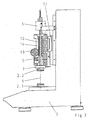
- the apparatus shown in the drawing is used to carry out component and material tests on samples 1, in particular of compression and tensile tests on springs and elastic components, assemblies and material samples.
- the device consists of two oppositely arranged sample receivers 2.1, 2.2, between which a force for loading between these sample holders 2.1, 2.2 arranged sample 1 can be generated.
- the lower of the two sample holders 2.1 is fixedly arranged on a base frame 3, while the other sample holder 2.2 is arranged on a movable adjusting element 4.
- a displacement sensor 5 is provided which is in communication with a displacement sensor 6.
- the upper sample holder 2.2 is in communication with a force transducer 7, which detects the force applied to the sample 1 force.
- the actuator 4 has in the embodiment of the Fig. 1 and 2 a standing with the sample holder 2.2, hollow-drilled spindle 8, which surrounds the displacement sensor 5 with a small distance.
- the manual or motor force application takes place, which takes place here also in consequence of the small distance to the measuring axis 9 coaxially.
- the spindle 8 itself is - as is clear from the Fig. 2 can be seen - attached via a spindle nut 10 in the adjusting element 4 and rotationally driven via a motor 15 via a gear 16.
- the actuator 4, as well as the FIG. 2 can recognize, connected via a play-free guide 11 on the base frame 3.
- FIGS. 3 to 5 show, instead of the spindle 8, a toothed rack provided with a toothing 12 extending in the axial direction can be used.
- this toothing 12 engages a pinion 13, via which the force is introduced into the rack 8.
- This can either - as indicated in the drawing - done by hand or be made by electric motor. Although the introduction of force is somewhat eccentric, it is still almost coaxial.
- the adjusting element 4 is in the region of the toothing, as is made Fig. 3 can be seen, provided with a recess 14 for the passage of the pinion 13.
- the toothing 12 can be introduced into the cylindrical lateral surface of the toothed rack 8, wherein the pinion 13 can have a shape adapted to the surface of the toothed rack 8 for this purpose.
- the rack 8 is provided, at least in the region of the toothing 12, with an axially extending free-cutting, whereby the toothed rack 8 forms a half-shell which only half encompasses the position sensor 5.
- both cut surfaces of the rack 8 are provided with a toothing 12, wherein the cut surfaces approximately in the plane of educaach lie, so that here the force is applied on both sides of the strigfach, but directly in the plane.
- each of the two gearing engages each arranged on a common shaft pinion, whereby the resulting force falls into the scholarachse.
- a pinion with a radial groove it is also possible to use instead a pinion with a radial groove.
Landscapes
- Physics & Mathematics (AREA)
- Health & Medical Sciences (AREA)
- Life Sciences & Earth Sciences (AREA)
- Chemical & Material Sciences (AREA)
- Analytical Chemistry (AREA)
- Biochemistry (AREA)
- General Health & Medical Sciences (AREA)
- General Physics & Mathematics (AREA)
- Immunology (AREA)
- Pathology (AREA)
- Investigating Strength Of Materials By Application Of Mechanical Stress (AREA)
- Transmission Devices (AREA)
Description
Die Erfindung betrifft eine Vorrichtung zur Durchführung von Bauteil- und Werkstoffprüfungen an Proben, insbesondere von Druck- und Zugversuchen an Federn und elastischen Bauteilen, Baugruppen und Werkstoffproben, mit zwei sich gegenüberstehend angeordneten Probenaufnahmen, zwischen denen eine Kraft zur Belastung der dazwischen angeordneten Probe erzeugbar ist, wobei die eine Probenaufnahme fest an einem Grundrahmen und die andere Probenaufnahme an einem verfahrbaren Stellelement angeordnet ist, ferner mit einem den Verfahrweg der Probenaufnahme über einen Messtaster erfassenden Wegaufnehmer sowie einem die auf die Probe aufgebrachte Kraft erfassenden Kraftaufnehmer.The invention relates to a device for performing component and material tests on samples, in particular of compression and tensile tests on springs and elastic components, assemblies and material samples, with two oppositely arranged sample receptacles, between which a force for loading the interposed sample can be generated wherein the one sample receptacle is fixedly arranged on a base frame and the other sample receptacle is arranged on a displaceable adjusting element, furthermore with a travel sensor for detecting the travel of the sample receptacle via a measuring transducer and a force transducer detecting the force applied to the sample.
Derartige Vorrichtungen sind in unterschiedlichen Ausführungsformen aus der Praxis bekannt, bei denen jedoch je nach konstruktivem Aufbau Messfehler erster Ordnung nach Abbe zu beobachten sind, soweit die zu messende Strecke und das Messnormal nicht in einer Flucht liegen.Such devices are known in practice in different embodiments, but in which, depending on the structural design measuring errors of the first order to Abbe are observed, as far as the distance to be measured and the measurement standard are not in alignment.
Weiter beschreibt die
Das aus der
Die
Weiter treten Kippfehler und elastische Verformungen dadurch auf, dass die Krafteinleitung üblicherweise außerhalb der Prüfachse erfolgt, wodurch ebenfalls die Messgenauigkeit beeinträchtigt wird.Furthermore, tilting errors and elastic deformations occur due to the fact that the introduction of force usually takes place outside the test axis, which likewise affects the measuring accuracy.
Der Erfindung liegt die Aufgabe zugrunde, eine Vorrichtung der eingangs genannten Art dahingehend zu verbessern, dass Messfehler in Folge von Kippbewegungen durch Krafteinleitung außerhalb der Prüfachse weitgehend minimiert werden und darüber hinaus die Vorrichtung so aufgebaut ist, dass statt der Ermittlung einzelner Messpunkte ein durchgehendes Kraft-Weg-Diagramm aufgenommen werden kann.The invention has for its object to improve a device of the type mentioned in that measurement errors due to tilting movements by force application outside the Prüfach be largely minimized and beyond the device is constructed so that instead of the determination of individual measuring points a continuous force Way diagram can be included.
Diese Aufgabe wird nach der Erfindung dadurch gelöst, dass das Stellelement ein hohl gebohrtes, den Wegtaster mit geringem Abstand umschließendes und mit der Probenaufnahme in Verbindung stehendes Krafteinleitungselement in Form einer Spindel, Zahnstange, eines Hydraulik- oder Pneumatikzylinders oder dergl. aufweist, über die die manuelle oder motorische Krafteinleitung koaxial oder zumindest nahezu koaxial zur Prüfachse erfolgt.This object is achieved according to the invention in that the actuator has a hollow drilled, the Wasteaster with a small distance enclosing and standing with the sample receiving force application element in the form of a spindle, rack, a hydraulic or pneumatic cylinder or the like., About the manual or motor force application coaxial or at least almost coaxial with the Prüffach done.
Der durch die Erfindung erreichte Vorteil besteht im wesentlichen darin, dass Kippmomente durch an dem Stellelement exzentrisch angreifende, der Verformung der Probe dienende Kräfte weitestgehend vermieden werden, so dass auch die hierdurch auftretenden Messfehler stark minimiert werden.The advantage achieved by the invention consists essentially in the fact that tilting moments by acting on the actuator eccentrically acting, the deformation of the sample serving forces are largely avoided, so that the measurement errors occurring thereby are greatly minimized.
In bevorzugter Ausführungsform der Erfindung ist dazu weiter in konstruktiver Hinsicht vorgesehen, dass bei als Spindel ausgebildetem Krafteinleitungselement diese über eine Spindelmutter in dem Stellelement befestigt ist.In a preferred embodiment of the invention is further provided to constructively that when trained as a spindle force introduction element it is attached via a spindle nut in the actuator.
Weiter empfiehlt es sich im Rahmen der Erfindung, dass das Stellelement über eine spielfreie Führung am Grundrahmen angeschlossen ist. Hierdurch können eventuell noch entstehende Querkräfte von dieser zusätzlichen Führung aufgenommen werden.Further, it is recommended in the invention that the control element is connected via a play-free guide on the base frame. As a result, any resulting lateral forces can be absorbed by this additional guide.
Um die Krafteinleitung bei als Zahnstange ausgebildetem Krafteinleitungselement vorzunehmen, schlägt die Erfindung vor, dass die Zahnstange mit einer in axialer Richtung verlaufenden Verzahnung versehen ist, in die die Krafteinleitung mittels eines Ritzels erfolgt.In order to carry out the introduction of force when trained as a rack force introduction element, the invention proposes that the rack is provided with a running in the axial direction of the toothing, in which the force is applied by means of a pinion.
Hierbei empfiehlt es sich weiter, dass das Stellelement im Bereich der Verzahnung mit einer Ausparung zum Durchtritt des Ritzels versehen ist.It is further recommended that the actuator is provided in the region of the toothing with a recess for the passage of the pinion.
Nach einer ersten Ausführungsform der Erfindung ist die Verzahnung in die zylindrische Mantelfläche der Zahnstange eingebracht. Hierbei kann das Ritzel eine der Mantelfläche der Zahnstange angepasste Außenkontur aufweisen.According to a first embodiment of the invention, the toothing is introduced into the cylindrical lateral surface of the rack. In this case, the pinion may have an outer contour adapted to the lateral surface of the rack.
Nach einer zweiten, messtechnisch noch vorteilhafteren Ausgestaltung der Erfindung ist die Zahnstange zumindest im Bereich der Verzahnung mit einer axial sich erstreckenden Freischneidung versehen, durch die eine den Wegtaster nur halb umgreifende Halbschale gebildet wird, wobei beide Schnittflächen mit einer Verzahnung versehen sind und in jeder Verzahnung jeweils ein auf einer gemeinsamen Welle angeordnetes Ritzel greift. Auf diese Weise erfolgt die Krafteinleitung gleichmäßig beidseits der eigentlichen Messachse, wobei die Krafteinleitung selbst bei entsprechender Gestaltung der Spindel unmittelbar in der Ebene der Messachse erfolgen kann. Diese Ausführungsform führt daher zu keinem oder allenfalls minimalsten Kippfehlern.After a second, metrologically even more advantageous embodiment of the invention, the rack is provided at least in the region of the toothing with an axially extending free cutting, through which a Wegtaster only half encompassing half shell is formed, both cut surfaces are provided with a toothing and engages in each toothing each arranged on a common shaft pinion. In this way, the introduction of force takes place uniformly on both sides of the actual measuring axis, wherein the force can be applied directly in the plane of the measuring axis even with a corresponding design of the spindle. This embodiment therefore leads to no or at most minimal tilt errors.
Im Folgenden wird die Erfindung an in der Zeichnung dargestellten Ausführungsbeispielen näher erläutert; es zeigen:
- Fig. 1
- den Gegenstand nach der Erfindung in einer Vorderansicht,
- Fig. 2
- den Gegenstand nach
Fig. 1 in Seitenansicht, teilweise im Schnitt dargestellt, - Fig. 3
- eine alternative Ausführungsform des Erfindungsgegenstandes in der
Fig. 2 entsprechender Darstellung, - Fig. 4
- die Zahnstange der Vorrichtung nach den
Fig. 1 und2 in einer ersten Ausführungsform in Seiten-, Stirn- und Draufsicht sowie im Schnitt dargestellt, - Fig. 5
- die Zahnstange in einer alternativen Ausführungsform, dargestellt entsprechend
Fig. 4 .
- Fig. 1
- the object according to the invention in a front view,
- Fig. 2
- the object after
Fig. 1 in side view, partially shown in section, - Fig. 3
- an alternative embodiment of the subject invention in the
Fig. 2 corresponding representation, - Fig. 4
- the rack of the device after the
Fig. 1 and2 in a first embodiment shown in side, front and top view and in section, - Fig. 5
- the rack in an alternative embodiment, shown accordingly
Fig. 4 ,
Die in der Zeichnung dargestellte Vorrichtung dient zur Durchführung von Bauteil- und Werkstoffprüfungen an Proben 1, insbesondere von Druck- und Zugversuchen an Federn und elastischen Bauteilen, Baugruppen und Werkstoffproben.The apparatus shown in the drawing is used to carry out component and material tests on
Im Einzelnen besteht die Vorrichtung aus zwei sich gegenüber stehend angeordneten Probenaufnahmen 2.1, 2.2, zwischen denen eine Kraft zur Belastung der zwischen diesen Probenaufnahmen 2.1, 2.2 angeordneten Probe 1 erzeugbar ist.In detail, the device consists of two oppositely arranged sample receivers 2.1, 2.2, between which a force for loading between these sample holders 2.1, 2.2 arranged
Die untere der beiden Probenaufnahmen 2.1 ist fest an einem Grundrahmen 3 angeordnet, während die andere Probenaufnahme 2.2 an einem verfahrbaren Stellelement 4 angeordnet ist.The lower of the two sample holders 2.1 is fixedly arranged on a
Um den Verfahrweg der oberen Probenaufnahme 2.2 erfassen zu können, ist ein Wegtaster 5 vorgesehen, der mit einem Wegaufnehmer 6 in Verbindung steht.In order to detect the travel path of the upper sample holder 2.2, a
Ferner steht die obere Probenaufnahme 2.2 mit einem Kraftaufnehmer 7 in Verbindung, der die auf die Probe 1 aufgebrachte Kraft erfasst.Furthermore, the upper sample holder 2.2 is in communication with a
Das Stellelement 4 weist in dem Ausführungsbeispiel nach den
Die Spindel 8 selbst ist - wie sich aus der
Wie die
Das Stellelement 4 ist im Bereich der Verzahnung, wie dies aus
Gemäß
Bei der Ausführungsform gemäß
In jeder der beiden Verzahnungem greift jeweils ein auf einer gemeinsamen Welle angeordnetes Ritzel, wodurch die resultierende Kraft in die Prüfachse fällt. Ebenso ist es auch möglich, statt dessen ein Ritzel mit radialem Einstich einzusetzen.In each of the two gearing engages each arranged on a common shaft pinion, whereby the resulting force falls into the Prüfachse. Likewise, it is also possible to use instead a pinion with a radial groove.
Claims (7)
- An apparatus for conducting component and material tests on samples, in particular compression and tensile tests on springs and elastic components, assemblies, and material samples, comprising two spaced sample holders (2.1, 2.2) between which a force can be generated so as to apply a load to the sample therebetween, wherein the one sample holder (2.1) is fixed to a base frame (3), while the other sample holder (2.2) is on a movable positioner (4), furthermore comprising a motion detector (6) that uses a probe (5) to record the travel distance of the sample holder (2.2), and comprising a force sensor (7) that records the force applied to the sample (1), characterized in that the positioner (4) includes a tubular force application element (8) that surrounds the probe (5) with a small clearance and is connected to the sample holder (2.2), the force application element being in the form of a spindle, gear rack, hydraulic unit, or pneumatic cylinder, or the like, through which the manual or motorized application of force is effected coaxially or at least nearly coaxially relative to the test axis (9).
- The apparatus according to claim 1, characterized in that in the case of a force application element (8) in the form of a spindle this spindle is attached by a spindle nut (10) to the positioner (4).
- The apparatus according to claims 1 or 2, characterized in that the positioner (4) is connected to the base frame (3) through a backlash-free guide (11).
- The apparatus according to one of claims 1 through 3, characterized in that the application of force is effected by a pinion (13) when the force application element (8) is a spindle having an axially extending rack (12).
- The apparatus according to claim 4, characterized in that the positioner (4) is formed with a cut-out (14) in the region of the rack (12) through the pinion (13) engages.
- The apparatus according to claims 4 or 5, characterized in that the rack (12) is formed in the cylindrical outer surface of the spindle (8).
- The apparatus according to claims 4 or 5, characterized in that the spindle (8) is provided with an axially extending cut-out at least in the region of the rack (12), thereby creating a tubular semicylinder that only half surrounds the probe (5), wherein both edges are provided with a rack (12), and one pinion (13) each on a common shaft engages each rack (12).
Applications Claiming Priority (2)
| Application Number | Priority Date | Filing Date | Title |
|---|---|---|---|
| DE102009036247A DE102009036247A1 (en) | 2009-08-05 | 2009-08-05 | Device for performing component and material tests on samples |
| PCT/DE2010/000681 WO2011015171A2 (en) | 2009-08-05 | 2010-06-17 | Device for performing component and material tests on samples |
Publications (2)
| Publication Number | Publication Date |
|---|---|
| EP2462422A2 EP2462422A2 (en) | 2012-06-13 |
| EP2462422B1 true EP2462422B1 (en) | 2013-10-09 |
Family
ID=43430100
Family Applications (1)
| Application Number | Title | Priority Date | Filing Date |
|---|---|---|---|
| EP10739472.8A Not-in-force EP2462422B1 (en) | 2009-08-05 | 2010-06-17 | Device for performing component and material tests on samples |
Country Status (4)
| Country | Link |
|---|---|
| US (1) | US20120192655A1 (en) |
| EP (1) | EP2462422B1 (en) |
| DE (1) | DE102009036247A1 (en) |
| WO (1) | WO2011015171A2 (en) |
Families Citing this family (7)
| Publication number | Priority date | Publication date | Assignee | Title |
|---|---|---|---|---|
| US9378662B2 (en) * | 2011-08-04 | 2016-06-28 | Ats Holdings Llc | Simplified spine testing device |
| CN103398898A (en) * | 2013-08-16 | 2013-11-20 | 常熟市苏常工程质量检测有限公司 | Anti-pressure testing device |
| DE102015201993A1 (en) | 2015-02-05 | 2016-08-11 | Zwick Gmbh & Co. Kg | Material sample holder with control unit |
| CN104749031B (en) * | 2015-04-13 | 2017-05-17 | 武汉理工大学 | Measurement jig and measurement method for rotary blade |
| CN109827839B (en) * | 2019-02-14 | 2021-02-09 | 南京航空航天大学 | Device and method for testing mechanical property of internal yarn of ceramic matrix composite |
| CN112577892B (en) * | 2020-12-11 | 2024-03-12 | 中国汽车工程研究院股份有限公司 | Gear rack type loading compression bar of material friction abnormal sound test bed |
| CN113701969B (en) * | 2021-10-27 | 2022-02-11 | 海安东洋弹簧有限公司 | Drilling rod spring compression performance check out test set |
Family Cites Families (4)
| Publication number | Priority date | Publication date | Assignee | Title |
|---|---|---|---|---|
| JPH05149851A (en) * | 1991-11-29 | 1993-06-15 | Toshin Kogyo Kk | Material tester |
| US6539809B1 (en) * | 1999-04-18 | 2003-04-01 | Testing Machines, Inc. | Test apparatus for measuring stresses and strains |
| EP1126269B1 (en) * | 2000-02-03 | 2008-03-26 | Mettler-Toledo AG | Device for dynamic mechanical sample analysis |
| JP4922527B2 (en) * | 2000-06-06 | 2012-04-25 | アジレント・テクノロジーズ・インク | Dynamic tensile testing machine |
-
2009
- 2009-08-05 DE DE102009036247A patent/DE102009036247A1/en not_active Withdrawn
-
2010
- 2010-06-17 WO PCT/DE2010/000681 patent/WO2011015171A2/en active Application Filing
- 2010-06-17 EP EP10739472.8A patent/EP2462422B1/en not_active Not-in-force
- 2010-06-17 US US13/387,145 patent/US20120192655A1/en not_active Abandoned
Also Published As
| Publication number | Publication date |
|---|---|
| WO2011015171A3 (en) | 2011-12-29 |
| WO2011015171A2 (en) | 2011-02-10 |
| US20120192655A1 (en) | 2012-08-02 |
| EP2462422A2 (en) | 2012-06-13 |
| DE102009036247A1 (en) | 2011-02-10 |
Similar Documents
| Publication | Publication Date | Title |
|---|---|---|
| EP2462422B1 (en) | Device for performing component and material tests on samples | |
| DE102008050465B4 (en) | Device for performing component and material tests on samples | |
| DE102011113540B4 (en) | Device for determining the biaxial strain characteristics of a sample | |
| DE102014200703A1 (en) | Test device for sheet materials and test methods | |
| EP1980835A1 (en) | Appartus for measuring bending stiffness | |
| EP0482360A2 (en) | Motor-driven press with load and displacement sensors | |
| DE4000180A1 (en) | DEVICE FOR DETERMINING MATERIAL HARDNESS | |
| WO2011015170A2 (en) | Device for performing component and material tests on samples | |
| EP1126269B1 (en) | Device for dynamic mechanical sample analysis | |
| DE2753549C2 (en) | Overload protection for a force measuring device | |
| DE10344544B3 (en) | Apparatus for mechanical testing of fiber-reinforced materials to determine pressure characteristic values, has clamping pads at clamping blocks operated by hydraulic cylinders on both workpiece ends | |
| EP1466157B1 (en) | Device for low-vibration force measurement in rapid dynamic tensile experiments on material samples | |
| DE3128537C2 (en) | ||
| DE102016123122B3 (en) | Haptic test measuring device and method for determining a force-displacement curve in a haptic test measurement | |
| DE102014107127B4 (en) | powder Press | |
| DE4327260C2 (en) | Manually operated hardness tester | |
| DE10319947B4 (en) | Device for measuring the circumferential shape of rotationally symmetrical workpieces | |
| DE3623362C2 (en) | ||
| DE19517215C1 (en) | Multi-coordinate probe | |
| EP2863172B1 (en) | Device and method for non-destructive measurement of the thickness of a layer of a plastic foam | |
| DE20314761U1 (en) | Mechanical material compression test fixture has C shaped clamp blocks on guide rods with test piece held in hydraulically clamped jaws | |
| DE2707873C2 (en) | Rockwell hardness tester | |
| DE914071C (en) | Method and device for determining the hardness of a material | |
| DE2750461A1 (en) | Displacement transducer for fracture toughness tests on metals - uses two rigid arms joined at one end by spring link to which strain-gauges are attached | |
| DE4422873A1 (en) | Manually-operated hardness tester |
Legal Events
| Date | Code | Title | Description |
|---|---|---|---|
| PUAI | Public reference made under article 153(3) epc to a published international application that has entered the european phase |
Free format text: ORIGINAL CODE: 0009012 |
|
| 17P | Request for examination filed |
Effective date: 20120131 |
|
| AK | Designated contracting states |
Kind code of ref document: A2 Designated state(s): AL AT BE BG CH CY CZ DE DK EE ES FI FR GB GR HR HU IE IS IT LI LT LU LV MC MK MT NL NO PL PT RO SE SI SK SM TR |
|
| DAX | Request for extension of the european patent (deleted) | ||
| 17Q | First examination report despatched |
Effective date: 20121213 |
|
| REG | Reference to a national code |
Ref country code: DE Ref legal event code: R079 Ref document number: 502010005019 Country of ref document: DE Free format text: PREVIOUS MAIN CLASS: G01N0003020000 Ipc: G01N0003040000 |
|
| RIC1 | Information provided on ipc code assigned before grant |
Ipc: G01N 3/04 20060101AFI20130423BHEP |
|
| GRAP | Despatch of communication of intention to grant a patent |
Free format text: ORIGINAL CODE: EPIDOSNIGR1 |
|
| INTG | Intention to grant announced |
Effective date: 20130605 |
|
| GRAS | Grant fee paid |
Free format text: ORIGINAL CODE: EPIDOSNIGR3 |
|
| GRAA | (expected) grant |
Free format text: ORIGINAL CODE: 0009210 |
|
| AK | Designated contracting states |
Kind code of ref document: B1 Designated state(s): AL AT BE BG CH CY CZ DE DK EE ES FI FR GB GR HR HU IE IS IT LI LT LU LV MC MK MT NL NO PL PT RO SE SI SK SM TR |
|
| REG | Reference to a national code |
Ref country code: GB Ref legal event code: FG4D Free format text: NOT ENGLISH |
|
| REG | Reference to a national code |
Ref country code: AT Ref legal event code: REF Ref document number: 635764 Country of ref document: AT Kind code of ref document: T Effective date: 20131015 Ref country code: CH Ref legal event code: EP Ref country code: CH Ref legal event code: NV Representative=s name: ISLER AND PEDRAZZINI AG, CH |
|
| REG | Reference to a national code |
Ref country code: IE Ref legal event code: FG4D Free format text: LANGUAGE OF EP DOCUMENT: GERMAN |
|
| REG | Reference to a national code |
Ref country code: DE Ref legal event code: R096 Ref document number: 502010005019 Country of ref document: DE Effective date: 20131205 |
|
| REG | Reference to a national code |
Ref country code: NL Ref legal event code: VDEP Effective date: 20131009 |
|
| PG25 | Lapsed in a contracting state [announced via postgrant information from national office to epo] |
Ref country code: SI Free format text: LAPSE BECAUSE OF FAILURE TO SUBMIT A TRANSLATION OF THE DESCRIPTION OR TO PAY THE FEE WITHIN THE PRESCRIBED TIME-LIMIT Effective date: 20131009 |
|
| REG | Reference to a national code |
Ref country code: LT Ref legal event code: MG4D |
|
| PG25 | Lapsed in a contracting state [announced via postgrant information from national office to epo] |
Ref country code: NL Free format text: LAPSE BECAUSE OF FAILURE TO SUBMIT A TRANSLATION OF THE DESCRIPTION OR TO PAY THE FEE WITHIN THE PRESCRIBED TIME-LIMIT Effective date: 20131009 Ref country code: HR Free format text: LAPSE BECAUSE OF FAILURE TO SUBMIT A TRANSLATION OF THE DESCRIPTION OR TO PAY THE FEE WITHIN THE PRESCRIBED TIME-LIMIT Effective date: 20131009 Ref country code: LT Free format text: LAPSE BECAUSE OF FAILURE TO SUBMIT A TRANSLATION OF THE DESCRIPTION OR TO PAY THE FEE WITHIN THE PRESCRIBED TIME-LIMIT Effective date: 20131009 Ref country code: SE Free format text: LAPSE BECAUSE OF FAILURE TO SUBMIT A TRANSLATION OF THE DESCRIPTION OR TO PAY THE FEE WITHIN THE PRESCRIBED TIME-LIMIT Effective date: 20131009 Ref country code: FI Free format text: LAPSE BECAUSE OF FAILURE TO SUBMIT A TRANSLATION OF THE DESCRIPTION OR TO PAY THE FEE WITHIN THE PRESCRIBED TIME-LIMIT Effective date: 20131009 Ref country code: IS Free format text: LAPSE BECAUSE OF FAILURE TO SUBMIT A TRANSLATION OF THE DESCRIPTION OR TO PAY THE FEE WITHIN THE PRESCRIBED TIME-LIMIT Effective date: 20140209 Ref country code: NO Free format text: LAPSE BECAUSE OF FAILURE TO SUBMIT A TRANSLATION OF THE DESCRIPTION OR TO PAY THE FEE WITHIN THE PRESCRIBED TIME-LIMIT Effective date: 20140109 |
|
| PG25 | Lapsed in a contracting state [announced via postgrant information from national office to epo] |
Ref country code: CY Free format text: LAPSE BECAUSE OF FAILURE TO SUBMIT A TRANSLATION OF THE DESCRIPTION OR TO PAY THE FEE WITHIN THE PRESCRIBED TIME-LIMIT Effective date: 20131009 Ref country code: ES Free format text: LAPSE BECAUSE OF FAILURE TO SUBMIT A TRANSLATION OF THE DESCRIPTION OR TO PAY THE FEE WITHIN THE PRESCRIBED TIME-LIMIT Effective date: 20131009 Ref country code: LV Free format text: LAPSE BECAUSE OF FAILURE TO SUBMIT A TRANSLATION OF THE DESCRIPTION OR TO PAY THE FEE WITHIN THE PRESCRIBED TIME-LIMIT Effective date: 20131009 Ref country code: PL Free format text: LAPSE BECAUSE OF FAILURE TO SUBMIT A TRANSLATION OF THE DESCRIPTION OR TO PAY THE FEE WITHIN THE PRESCRIBED TIME-LIMIT Effective date: 20131009 |
|
| PG25 | Lapsed in a contracting state [announced via postgrant information from national office to epo] |
Ref country code: PT Free format text: LAPSE BECAUSE OF FAILURE TO SUBMIT A TRANSLATION OF THE DESCRIPTION OR TO PAY THE FEE WITHIN THE PRESCRIBED TIME-LIMIT Effective date: 20140210 |
|
| REG | Reference to a national code |
Ref country code: DE Ref legal event code: R097 Ref document number: 502010005019 Country of ref document: DE |
|
| PG25 | Lapsed in a contracting state [announced via postgrant information from national office to epo] |
Ref country code: EE Free format text: LAPSE BECAUSE OF FAILURE TO SUBMIT A TRANSLATION OF THE DESCRIPTION OR TO PAY THE FEE WITHIN THE PRESCRIBED TIME-LIMIT Effective date: 20131009 |
|
| PLBE | No opposition filed within time limit |
Free format text: ORIGINAL CODE: 0009261 |
|
| STAA | Information on the status of an ep patent application or granted ep patent |
Free format text: STATUS: NO OPPOSITION FILED WITHIN TIME LIMIT |
|
| PG25 | Lapsed in a contracting state [announced via postgrant information from national office to epo] |
Ref country code: CZ Free format text: LAPSE BECAUSE OF FAILURE TO SUBMIT A TRANSLATION OF THE DESCRIPTION OR TO PAY THE FEE WITHIN THE PRESCRIBED TIME-LIMIT Effective date: 20131009 Ref country code: SK Free format text: LAPSE BECAUSE OF FAILURE TO SUBMIT A TRANSLATION OF THE DESCRIPTION OR TO PAY THE FEE WITHIN THE PRESCRIBED TIME-LIMIT Effective date: 20131009 Ref country code: RO Free format text: LAPSE BECAUSE OF FAILURE TO SUBMIT A TRANSLATION OF THE DESCRIPTION OR TO PAY THE FEE WITHIN THE PRESCRIBED TIME-LIMIT Effective date: 20131009 Ref country code: IT Free format text: LAPSE BECAUSE OF FAILURE TO SUBMIT A TRANSLATION OF THE DESCRIPTION OR TO PAY THE FEE WITHIN THE PRESCRIBED TIME-LIMIT Effective date: 20131009 |
|
| 26N | No opposition filed |
Effective date: 20140710 |
|
| PG25 | Lapsed in a contracting state [announced via postgrant information from national office to epo] |
Ref country code: DK Free format text: LAPSE BECAUSE OF FAILURE TO SUBMIT A TRANSLATION OF THE DESCRIPTION OR TO PAY THE FEE WITHIN THE PRESCRIBED TIME-LIMIT Effective date: 20131009 |
|
| REG | Reference to a national code |
Ref country code: DE Ref legal event code: R097 Ref document number: 502010005019 Country of ref document: DE Effective date: 20140710 |
|
| PG25 | Lapsed in a contracting state [announced via postgrant information from national office to epo] |
Ref country code: MC Free format text: LAPSE BECAUSE OF FAILURE TO SUBMIT A TRANSLATION OF THE DESCRIPTION OR TO PAY THE FEE WITHIN THE PRESCRIBED TIME-LIMIT Effective date: 20131009 Ref country code: LU Free format text: LAPSE BECAUSE OF FAILURE TO SUBMIT A TRANSLATION OF THE DESCRIPTION OR TO PAY THE FEE WITHIN THE PRESCRIBED TIME-LIMIT Effective date: 20140617 |
|
| REG | Reference to a national code |
Ref country code: IE Ref legal event code: MM4A |
|
| PG25 | Lapsed in a contracting state [announced via postgrant information from national office to epo] |
Ref country code: IE Free format text: LAPSE BECAUSE OF NON-PAYMENT OF DUE FEES Effective date: 20140617 |
|
| REG | Reference to a national code |
Ref country code: FR Ref legal event code: PLFP Year of fee payment: 7 |
|
| PG25 | Lapsed in a contracting state [announced via postgrant information from national office to epo] |
Ref country code: MT Free format text: LAPSE BECAUSE OF FAILURE TO SUBMIT A TRANSLATION OF THE DESCRIPTION OR TO PAY THE FEE WITHIN THE PRESCRIBED TIME-LIMIT Effective date: 20131009 |
|
| PG25 | Lapsed in a contracting state [announced via postgrant information from national office to epo] |
Ref country code: SM Free format text: LAPSE BECAUSE OF FAILURE TO SUBMIT A TRANSLATION OF THE DESCRIPTION OR TO PAY THE FEE WITHIN THE PRESCRIBED TIME-LIMIT Effective date: 20131009 |
|
| PG25 | Lapsed in a contracting state [announced via postgrant information from national office to epo] |
Ref country code: GR Free format text: LAPSE BECAUSE OF FAILURE TO SUBMIT A TRANSLATION OF THE DESCRIPTION OR TO PAY THE FEE WITHIN THE PRESCRIBED TIME-LIMIT Effective date: 20140110 Ref country code: BG Free format text: LAPSE BECAUSE OF FAILURE TO SUBMIT A TRANSLATION OF THE DESCRIPTION OR TO PAY THE FEE WITHIN THE PRESCRIBED TIME-LIMIT Effective date: 20131009 |
|
| PG25 | Lapsed in a contracting state [announced via postgrant information from national office to epo] |
Ref country code: HU Free format text: LAPSE BECAUSE OF FAILURE TO SUBMIT A TRANSLATION OF THE DESCRIPTION OR TO PAY THE FEE WITHIN THE PRESCRIBED TIME-LIMIT; INVALID AB INITIO Effective date: 20100617 Ref country code: TR Free format text: LAPSE BECAUSE OF FAILURE TO SUBMIT A TRANSLATION OF THE DESCRIPTION OR TO PAY THE FEE WITHIN THE PRESCRIBED TIME-LIMIT Effective date: 20131009 |
|
| REG | Reference to a national code |
Ref country code: FR Ref legal event code: PLFP Year of fee payment: 8 |
|
| REG | Reference to a national code |
Ref country code: FR Ref legal event code: PLFP Year of fee payment: 9 |
|
| PG25 | Lapsed in a contracting state [announced via postgrant information from national office to epo] |
Ref country code: MK Free format text: LAPSE BECAUSE OF FAILURE TO SUBMIT A TRANSLATION OF THE DESCRIPTION OR TO PAY THE FEE WITHIN THE PRESCRIBED TIME-LIMIT Effective date: 20131009 |
|
| PG25 | Lapsed in a contracting state [announced via postgrant information from national office to epo] |
Ref country code: AL Free format text: LAPSE BECAUSE OF FAILURE TO SUBMIT A TRANSLATION OF THE DESCRIPTION OR TO PAY THE FEE WITHIN THE PRESCRIBED TIME-LIMIT Effective date: 20131009 |
|
| PGFP | Annual fee paid to national office [announced via postgrant information from national office to epo] |
Ref country code: BE Payment date: 20190527 Year of fee payment: 10 Ref country code: FR Payment date: 20190410 Year of fee payment: 10 |
|
| PGFP | Annual fee paid to national office [announced via postgrant information from national office to epo] |
Ref country code: CH Payment date: 20190611 Year of fee payment: 10 |
|
| PGFP | Annual fee paid to national office [announced via postgrant information from national office to epo] |
Ref country code: GB Payment date: 20190624 Year of fee payment: 10 Ref country code: AT Payment date: 20190607 Year of fee payment: 10 Ref country code: DE Payment date: 20190816 Year of fee payment: 10 |
|
| REG | Reference to a national code |
Ref country code: DE Ref legal event code: R119 Ref document number: 502010005019 Country of ref document: DE |
|
| REG | Reference to a national code |
Ref country code: CH Ref legal event code: PL |
|
| REG | Reference to a national code |
Ref country code: AT Ref legal event code: MM01 Ref document number: 635764 Country of ref document: AT Kind code of ref document: T Effective date: 20200617 |
|
| GBPC | Gb: european patent ceased through non-payment of renewal fee |
Effective date: 20200617 |
|
| REG | Reference to a national code |
Ref country code: BE Ref legal event code: MM Effective date: 20200630 |
|
| PG25 | Lapsed in a contracting state [announced via postgrant information from national office to epo] |
Ref country code: FR Free format text: LAPSE BECAUSE OF NON-PAYMENT OF DUE FEES Effective date: 20200630 Ref country code: GB Free format text: LAPSE BECAUSE OF NON-PAYMENT OF DUE FEES Effective date: 20200617 Ref country code: LI Free format text: LAPSE BECAUSE OF NON-PAYMENT OF DUE FEES Effective date: 20200630 Ref country code: CH Free format text: LAPSE BECAUSE OF NON-PAYMENT OF DUE FEES Effective date: 20200630 |
|
| PG25 | Lapsed in a contracting state [announced via postgrant information from national office to epo] |
Ref country code: AT Free format text: LAPSE BECAUSE OF NON-PAYMENT OF DUE FEES Effective date: 20200617 Ref country code: BE Free format text: LAPSE BECAUSE OF NON-PAYMENT OF DUE FEES Effective date: 20200630 Ref country code: DE Free format text: LAPSE BECAUSE OF NON-PAYMENT OF DUE FEES Effective date: 20210101 |