EP2461345B1 - Configurable electrical switching apparatus including a plurality of separable contacts and a plurality of field-configurable jumpers to provide a number of poles - Google Patents
Configurable electrical switching apparatus including a plurality of separable contacts and a plurality of field-configurable jumpers to provide a number of poles Download PDFInfo
- Publication number
- EP2461345B1 EP2461345B1 EP11009554.4A EP11009554A EP2461345B1 EP 2461345 B1 EP2461345 B1 EP 2461345B1 EP 11009554 A EP11009554 A EP 11009554A EP 2461345 B1 EP2461345 B1 EP 2461345B1
- Authority
- EP
- European Patent Office
- Prior art keywords
- terminals
- field
- separable contacts
- switching apparatus
- pairs
- Prior art date
- Legal status (The legal status is an assumption and is not a legal conclusion. Google has not performed a legal analysis and makes no representation as to the accuracy of the status listed.)
- Active
Links
- 239000004020 conductor Substances 0.000 claims description 9
- 230000007246 mechanism Effects 0.000 description 5
- 230000008878 coupling Effects 0.000 description 2
- 238000010168 coupling process Methods 0.000 description 2
- 238000005859 coupling reaction Methods 0.000 description 2
- RYGMFSIKBFXOCR-UHFFFAOYSA-N Copper Chemical compound [Cu] RYGMFSIKBFXOCR-UHFFFAOYSA-N 0.000 description 1
- 229910052782 aluminium Inorganic materials 0.000 description 1
- XAGFODPZIPBFFR-UHFFFAOYSA-N aluminium Chemical compound [Al] XAGFODPZIPBFFR-UHFFFAOYSA-N 0.000 description 1
- 230000002457 bidirectional effect Effects 0.000 description 1
- 230000015572 biosynthetic process Effects 0.000 description 1
- 238000010276 construction Methods 0.000 description 1
- 229910052802 copper Inorganic materials 0.000 description 1
- 239000010949 copper Substances 0.000 description 1
- 230000001419 dependent effect Effects 0.000 description 1
- 238000010586 diagram Methods 0.000 description 1
- 230000006872 improvement Effects 0.000 description 1
- 238000009434 installation Methods 0.000 description 1
- 239000000463 material Substances 0.000 description 1
- 229910052751 metal Inorganic materials 0.000 description 1
- 239000002184 metal Substances 0.000 description 1
- 230000004048 modification Effects 0.000 description 1
- 238000012986 modification Methods 0.000 description 1
- 230000005405 multipole Effects 0.000 description 1
- 230000004044 response Effects 0.000 description 1
- 239000007787 solid Substances 0.000 description 1
Images


Classifications
-
- H—ELECTRICITY
- H01—ELECTRIC ELEMENTS
- H01H—ELECTRIC SWITCHES; RELAYS; SELECTORS; EMERGENCY PROTECTIVE DEVICES
- H01H71/00—Details of the protective switches or relays covered by groups H01H73/00 - H01H83/00
- H01H71/08—Terminals; Connections
-
- H—ELECTRICITY
- H01—ELECTRIC ELEMENTS
- H01H—ELECTRIC SWITCHES; RELAYS; SELECTORS; EMERGENCY PROTECTIVE DEVICES
- H01H11/00—Apparatus or processes specially adapted for the manufacture of electric switches
- H01H11/0006—Apparatus or processes specially adapted for the manufacture of electric switches for converting electric switches
- H01H11/0031—Apparatus or processes specially adapted for the manufacture of electric switches for converting electric switches for allowing different types or orientation of connections to contacts
-
- H—ELECTRICITY
- H01—ELECTRIC ELEMENTS
- H01H—ELECTRIC SWITCHES; RELAYS; SELECTORS; EMERGENCY PROTECTIVE DEVICES
- H01H71/00—Details of the protective switches or relays covered by groups H01H73/00 - H01H83/00
- H01H71/08—Terminals; Connections
- H01H71/082—Connections between juxtaposed circuit breakers
-
- H—ELECTRICITY
- H01—ELECTRIC ELEMENTS
- H01H—ELECTRIC SWITCHES; RELAYS; SELECTORS; EMERGENCY PROTECTIVE DEVICES
- H01H71/00—Details of the protective switches or relays covered by groups H01H73/00 - H01H83/00
- H01H71/10—Operating or release mechanisms
- H01H71/1045—Multiple circuits-breaker, e.g. for the purpose of dividing current or potential drop
-
- H—ELECTRICITY
- H01—ELECTRIC ELEMENTS
- H01R—ELECTRICALLY-CONDUCTIVE CONNECTIONS; STRUCTURAL ASSOCIATIONS OF A PLURALITY OF MUTUALLY-INSULATED ELECTRICAL CONNECTING ELEMENTS; COUPLING DEVICES; CURRENT COLLECTORS
- H01R31/00—Coupling parts supported only by co-operation with counterpart
- H01R31/08—Short-circuiting members for bridging contacts in a counterpart
Description
- The disclosed concept pertains generally to electrical switching apparatus and, more particularly, to circuit breakers including a plurality of separable contacts.
-
U.S. Patent No. 6,614,334 discloses a series arrangement of two circuit breaker mechanisms. The interruption performance of the circuit breaker is determined by the "current limitation of series arcs," which provides two arcs in series, thereby having twice the resistance of a single arc. - It is known to connect multiple poles of circuit breakers in series to provide a high voltage for a low voltage switching and interruption device (e.g., without limitation, 750 VDC; 1000 VDC; 1500 VAC).
- Circuit breakers are typically available in one-, two-, three- and four-pole construction, although larger counts of poles are possible.
- For a 1000 VDC application, typically multiple circuit breakers are tied together. Most known existing six-pole or eight-pole air circuit breakers are designed such that the poles are electrically connected internally in breaker structures in a predetermined manner. This limits the flexibility of wiring the six-pole or eight-pole circuit breakers in switchgear and switchboards.
-
FR 2 427 679 A1 - Furthermore,
EP 2 189 996 A1 relates to a circuit breaker device for bidirectional direct current and an installation with photovoltaic cells provided with such a device. The device has a predefined even number of separable contacts comprising two contacts electrically connected to connection terminals. Arc chutes are provided with respective arc formation chambers. Tripping mechanisms are associated with respective pairs of separable contacts to separate the separable contacts of the pairs in response to electric faults in an electric line. The tripping mechanisms are connected to each other by a mechanical link permitting simultaneous opening of separable contacts. - There is room for improvement in electrical switching apparatus, such as circuit breakers including a plurality of separable contacts.
- In accordance with the present invention, an electrical switching apparatus as set forth in claim 1 is provided. Further embodiments are claimed in the dependent claims. These needs and others are met by embodiments of the disclosed concept, in which the electrical switching apparatus inter alia comprises: at least one pole; a plurality of first terminals; a plurality of second terminals; a plurality of pairs of separable contacts; and a plurality of field-configurable jumpers, each of the plurality of field-configurable jumpers electrically connecting two of the pairs of separable contacts in series, each of the plurality of field-configurable jumpers being electrically connected to: (a) two of the first terminals, (b) two of the first terminals or two of the second terminals; or (c) one of the first terminals and one of the second terminals.
- N may be an integer count of the at least one pole; the N of the plurality of first terminals may be input terminals; the N of the plurality of second terminals may be output terminals; two of the pairs of separable contacts may be electrically connected in series for each of the at least one pole; and each of the N of the plurality of field-configurable jumpers may be electrically connected between one of the plurality of first terminals that may be not one of the input terminals and one of the plurality of second terminals that may be not one of the output terminals.
- The at least one pole may be the integer count N of a plurality of poles structured to power an AC load having the integer count N of a plurality of phases.
- Each of the plurality of field-configurable jumpers may be electrically connected to the one of the first terminals and the one of the second terminals.
- N may be an integer count of the at least one pole; the N of the plurality of second terminals may be input terminals; the N of the plurality of second terminals may be output terminals; two of the pairs of separable contacts may be electrically connected in series for each of the at least one pole; and each of the N of the plurality of field-configurable jumpers may be electrically connected between two of the plurality of first terminals.
- Each of the plurality of field-configurable jumpers may be electrically connected to the two of the first terminals.
- Two of the plurality of first terminals may be input terminals; two of the plurality of second terminals may be output terminals; N may be an integer count of the plurality of field-configurable jumpers; two of the pairs of separable contacts may be electrically connected to the output terminals; half of the N field-configurable jumpers may electrically connect half of the pairs of separable contacts in series between one of the input terminals and one of the output terminals; the other half of the N field-configurable jumpers may electrically connect the other half of the pairs of separable contacts in series between the other one of the input terminals and the other one of the output terminals; and the output terminals may be structured for electrical connection to a load.
- One of the plurality of first terminals may be an input terminal; another one of the plurality of first terminals may be an output terminal; N may be an integer count of the plurality of field-configurable jumpers; one of the pairs of separable contacts may be electrically connected to the input terminal; another one of the pairs of separable contacts may be electrically connected to the output terminal; the N of the plurality of field-configurable jumpers may electrically connect the pairs of separable contacts in series between the input terminal and the output terminal; and the input terminal and the output terminal may be structured to receive the series combination of a load and a power source.
- Each of the plurality of field-configurable jumpers may be electrically connected to the two of the first terminals or two of the second terminals.
- A full understanding of the disclosed concept can be gained from the following description of the preferred embodiments when read in conjunction with the accompanying drawings in which:
-
Figures 1-4 are block diagrams in schematic form of terminals, separable contacts and jumpers of electrical switching apparatus in accordance with embodiments of the disclosed concept. -
Figures 5-8 are isometric views of the electrical switching apparatus ofFigures 1-4 , respectively. - As employed herein, the term "number" shall mean one or an integer greater than one (i.e., a plurality).
- As employed herein, the term "fastener" shall mean screws, bolts and the combinations of bolts and nuts (e.g., without limitation, lock nuts) and bolts, washers and nuts.
- As employed herein, the term "electrical conductor" shall mean a wire (e.g., solid; stranded; insulated; non-insulated), a copper conductor, an aluminum conductor, a suitable metal conductor, or other suitable material or object that permits an electric current to flow easily.
- As employed herein, the term "low voltage" shall mean a voltage less than or equal to about 1000 VAC or about 750 VDC.
- As employed herein, the term "high voltage for a low voltage device" shall mean greater than a "low voltage" and up to approximately 1500 volts, although this may be slightly higher depending upon the application but no more than 2000 volts.
- As employed herein, the statement that two or more parts are "connected" or "coupled" together shall mean that the parts are joined together either directly or joined through one or more intermediate parts. Further, as employed herein, the statement that two or more parts are "attached" shall mean that the parts are joined together directly.
- The disclosed concept is described in association with six-pole circuit breakers (i.e., having six pairs of separable contacts), although the disclosed concept is applicable to a wide range of electrical switching apparatus having eight poles (i.e., having eight pairs of separable contacts) or any other suitable plurality of poles.
- An example six-pole air circuit breaker as disclosed herein can include terminals accessible for every pole for both high voltage (for a low voltage device) AC and DC applications. With accessibility to terminals of each pole, the six-pole circuit breaker can be wired or otherwise configured in different ways. For example, with six poles electrically connected in series, it can be used for applications with systems voltages over 600 VDC. With two poles tied in series, for instance, it can be used for three-phase applications over 600 VAC.
- In a "potentially grounded load", the system ground could be either at the power end or at the load (at the site).
- The disclosed concept can be employed, for example and without limitation, for "green" systems (e.g., wind and solar segments).
- Referring to
Figures 1-4 , configured electrical switching apparatus, such as circuit breakers 100,200,300,400, include at least one pole. For example, three configured poles 102,202 are shown in respectiveFigures 1 and 2 , and one configured pole 302,402 is shown inFigures 3 and 4 , respectively. The circuit breakers 100,200,300,400 further include a plurality of first terminals 104,204,304,404, a plurality of second terminals 106,206,306,406, a plurality of pairs of separable contacts 108,208,308,408, and a plurality of field-configurable jumpers 110,210,310,410, respectively. Each of the plurality of field-configurable jumpers 110,210,310,410 electrically connects two of the respective pairs of separable contacts 108,208,308,408 in series. Each of the plurality of field-configurable jumpers 110,210,310,410 is electrically connected to: (a) two of thefirst terminals 204 as shown with thejumpers 210 inFigure 2 , (b) two of the first terminals 304,404 or two of the second terminals 306,406 as shown with the jumpers 310,410 inFigures 3 and 4 , respectively, or (c) one of thefirst terminals 104 and one of thesecond terminals 106 as shown with thejumpers 110 inFigure 1 . - It will be appreciated that the example circuit breakers 100,200,300,400 can be the same or similar devices except for the specific example configurations of the various field-configurable jumpers 110,210,310,410.
- For example, with reference to
Figure 1 , N=3 is a non-limiting example integer count of the threeexample poles 102. N of the plurality offirst terminals 104 are input terminals. N of the plurality ofsecond terminals 106 are output terminals. Two of the pairs ofseparable contacts 108 are electrically connected in series for each of the threeexample poles 102. Each of N of the plurality of field-configurable jumpers 110 is electrically connected between one of the plurality offirst terminals 104 that is not one of the input terminals and one of the plurality ofsecond terminals 106 that is not one of the output terminals. For example, thecircuit breaker 100, as configured inFigure 1 , can input three input phases 112 (as shown in phantom line drawing) (e.g., without limitation, phases A, B and C from an example three-phase power source (not shown)) and output three output phases 114 (as shown in phantom line drawing) (e.g., without limitation, phases A, B and C to an example three-phase load (not shown)). - The three
example poles 102 are structured to power an AC load (not shown) having three example phases. It will be appreciated, however, that any suitable number of phases can be employed for either AC or DC loads. - For example, with reference to
Figure 2 , N=3 is an example non-limiting integer count of the threeexample poles 202. N of the plurality ofsecond terminals 206 are input terminals. N of the plurality ofsecond terminals 206 are output terminals. Two of the pairs ofseparable contacts 208 are electrically connected in series for each of the threeexample poles 202. Each of N of the field-configurable jumpers 210 is electrically connected between two of the plurality offirst terminals 204. For example, thecircuit breaker 200, as configured inFigure 2 , can input three input phases 212 (as shown in phantom line drawing) (from an example three-phase power source (not shown)) and output three output phases 214 (as shown in phantom line drawing) (to an example three-phase load (not shown)). - The three
example poles 202 are structured to power an AC load (not shown) having three example phases. It will be appreciated, however, that any suitable number of phases can be employed for either AC or DC loads. - For example, with reference to
Figure 3 , two of the plurality offirst terminals 304 are input terminals, two of the plurality ofsecond terminals 306 are output terminals for a load 312 (shown in phantom line drawing), N=4 is an example integer count of the plurality of field-configurable jumpers 310, two of the pairs ofseparable contacts 308 are electrically connected to the output terminals for theload 312, half (N/2=2) of the N field-configurable jumpers 310 electrically connect half of the pairs ofseparable contacts 308 in series between one of theinput terminals 304 and one of the output terminals for theload 312, and the other half of the N field-configurable jumpers 310 electrically connect the other half of the pairs ofseparable contacts 308 in series between the other one of theinput terminals 304 and the other one of the output terminals for theload 312. - The
example load 312 is a DC load, and theexample pole 302 is structured to power the DC load. For example, thecircuit breaker 300, as configured inFigure 3 , can input one DC input 314 (as shown in phantom line drawing) (from an example DC power source (not shown)) and output one DC output 316 (as shown in phantom line drawing) to theexample DC load 312. - For example, with reference to
Figure 4 , one of the plurality offirst terminals 404 is an input terminal, another one of the plurality offirst terminals 404 is an output terminal, N=5 is an integer count of the plurality of field-configurable jumpers 410, one of the pairs ofseparable contacts 408 is electrically connected to the input terminal, another one of the pairs ofseparable contacts 408 is electrically connected to the output terminal, N of the plurality of field-configurable jumpers 410 electrically connect the pairs ofseparable contacts 408 in series between the input terminal and the output terminal, and the input terminal and the output terminal are structured to receive the series combination of aload 412 and apower source 414. - The
example load 412 is a DC load, and thepole 402 is structured to power the DC load. For example, thecircuit breaker 400, as configured inFigure 4 , can input one DC input from the DC power source 414 (as shown in phantom line drawing) for theDC load 412. -
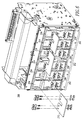
Figures 5-8 shows the respective circuit breakers 100,200,300,400. It will be appreciated that the separable contacts 108,208,308,408 ofFigures 1-4 , respectively, are not shown along with the corresponding circuit breaker operating mechanism (not shown) and trip unit (not shown). - As shown in
Figure 5 , each of the field-configurable jumpers 110 is an electrical conductor including a firstplanar portion 116, a secondplanar portion 118 and a thirdplanar portion 120. The firstplanar portion 116 is parallel to the thirdplanar portion 120. The secondplanar portion 118 is normal to the firstplanar portion 116 and to the thirdplanar portion 120. The firstplanar portion 116 is electrically connected to one of thefirst terminals 104 by a number offasteners 122. The thirdplanar portion 120 is electrically connected to one of thesecond terminals 106 by a number offasteners 124. The example secondplanar portion 118 is a non-rectangular parallelogram, in order to accommodate the width offset and the height offset between the corresponding terminals 104,106. - As shown in
Figures 6-8 , each of the field-configurable jumpers 210,310,410 is a planar U-shaped electrical conductor. - While specific embodiments of the disclosed concept have been described in detail, it will be appreciated by those skilled in the art that various modifications and alternatives to those details could be developed in light of the overall teachings of the disclosure. Accordingly, the particular arrangements disclosed are meant to be illustrative only and not limiting as to the scope of the disclosed concept which is to be given the full breadth of the claims appended.
-
- 100
- electrical switching apparatus, such as a circuit breaker
- 102
- three poles
- 104
- plurality of first terminals
- 106
- plurality of second terminals
- 108
- plurality of pairs of separable contacts
- 110
- plurality of field-configurable jumpers
- 112
- three input phases
- 114
- three output phases
- 116
- first planar portion
- 118
- second planar portion
- 120
- third planar portion
- 122
- number of fasteners
- 124
- number of fasteners
- 200
- circuit breaker
- 202
- three poles
- 204
- plurality of first terminals
- 206
- plurality of second terminals
- 208
- plurality of pairs of separable contacts
- 210
- plurality of field-configurable jumpers
- 212
- three input phases
- 214
- three output phases
- 300
- circuit breaker
- 302
- pole
- 304
- plurality of first terminals
- 306
- plurality of second terminals
- 308
- plurality of pairs of separable contacts
- 310
- plurality of field-configurable jumpers
- 312
- load
- 314
- DC input
- 316
- DC output
- 400
- circuit breaker
- 402
- pole
- 404
- plurality of first terminals
- 406
- plurality of second terminals
- 408
- plurality of pairs of separable contacts
- 410
- plurality of field-configurable jumpers
- 412
- load
- 414
- power source
Claims (15)
- An electrical switching apparatus (100; 200; 300; 400) comprising:at least one pole (102; 202; 302; 402);a plurality of first terminals (104; 204; 304; 404);a plurality of second terminals (106; 206; 306; 406);a plurality of pairs of separable contacts (108; 208; 308; 408); and
a plurality of field-configurable jumpers (110; 210; 310; 410), each of said plurality of field-configurable jumpers electrically connecting two of said pairs of separable contacts in series, each of said plurality of field-configurable jumpers being electrically connected to: (a) two of said first terminals (204), (b) two of said first terminals (304; 404) or two of said second terminals (306; 406); or (c) one of said first terminals (104) and one of said second terminals (106),characterized in thatsaid first terminals (104; 204; 304; 404) are disposed above said second terminals (106; 206; 306; 406), andin that all of said first terminals (104; 204; 304; 404), said second terminals (106; 206; 306; 406) and said field-configurable jumpers (110; 210; 310; 410) are accessible from one side of said electrical switching apparatus (100; 200; 300; 400). - The electrical switching apparatus (100) of Claim 1 wherein N is an integer count of said at least one pole (102); wherein said N of said plurality of first terminals are input terminals (104); wherein said N of said plurality of second terminals are output terminals (106); wherein two of said pairs of separable contacts (108) are electrically connected in series for each of said at least one pole; and wherein each of said N of said plurality of field-configurable jumpers (110) is electrically connected between one of said plurality of first terminals that is not one of said input terminals and one of said plurality of second terminals that is not one of said output terminals.
- The electrical switching apparatus (100) of Claim 1 wherein N is an integer count of said at least one pole; wherein said N of said plurality of second terminals are input terminals; wherein said N of said plurality of second terminals are output terminals; wherein two of said pairs of separable contacts are electrically connected in series for each of said at least one pole; and wherein each of said N of said plurality of field-configurable jumpers is electrically connected between two of said plurality of first terminals.
- The electrical switching apparatus (300) of Claim 1 wherein two of said plurality of first terminals are input terminals (304); wherein two of said plurality of second terminals are output terminals (306); wherein N is an integer count of said plurality of field-configurable jumpers (310); wherein two of said pairs of separable contacts (308) are electrically connected to said output terminals; wherein half of said N field-configurable jumpers electrically connect half of said pairs of separable contacts in series between one of said input terminals and one of said output terminals; wherein the other half of said N field-configurable jumpers electrically connect the other half of said pairs of separable contacts in series between the other one of said input terminals and the other one of said output terminals; and wherein said output terminals are structured for electrical connection to a load (312).
- The electrical switching apparatus (400) of Claim 1 wherein one of said plurality of first terminals is an input terminal (404); wherein another one of said plurality of first terminals is an output terminal (404); wherein N is an integer count of said plurality of field-configurable jumpers (410); wherein one of said pairs of separable contacts (408) is electrically connected to said input terminal; wherein another one of said pairs of separable contacts is electrically connected to said output terminal; wherein said N of said plurality of field-configurable jumpers electrically connect said pairs of separable contacts in series between said input terminal and said output terminal; and wherein said input terminal and said output terminal are structured to receive the series combination of a load (412) and a power source (414).
- The electrical switching apparatus (300; 400) of Claims 4 or 5 wherein said load is a DC load (312; 412); and wherein said at least one pole is one pole (302; 402) structured to power said DC load.
- The electrical switching apparatus (200) of Claim 1 wherein said each of said plurality of field-configurable jumpers (210) is electrically connected to said two of said first terminals (204).
- The electrical switching apparatus (200) of Claim 7 wherein said at least one pole is a plurality of poles (202) structured to power an AC load having a plurality of phases.
- The electrical switching apparatus (300; 400) of Claim 1 wherein said each of said plurality of field-configurable jumpers (310;410) is electrically connected to said two of said first terminals (304; 404) or two of said second terminals (306; 406).
- The electrical switching apparatus (300; 400) of Claim 9 wherein said at least one pole is one pole (302; 402) structured to power a DC load (312; 412).
- The electrical switching apparatus (300; 400) of Claim 10 wherein said plurality of first terminals are six first terminals (304; 404); wherein said plurality of second terminals are six second terminals (306; 406); wherein said plurality of pairs of separable contacts are six pairs of separable contacts (308; 408); and wherein said plurality of field-configurable jumpers are four or five field-configurable jumpers (310; 410).
- The electrical switching apparatus (100) of Claim 1 wherein said each of said plurality of field-configurable jumpers (110) is electrically connected to said one of said first terminals (104) and said one of said second terminals (66).
- The electrical switching apparatus (100) of Claim 12 wherein said at least one pole is a plurality of poles (102) structured to power an AC load having a plurality of phases.
- The electrical switching apparatus of Claim 1 wherein each of said plurality of field-configurable jumpers is a planar U-shaped electrical conductor (210; 310; 410).
- The electrical switching apparatus of Claim 1 wherein each of said plurality of field-configurable jumpers is an electrical conductor (110) including a first planar portion (116), a second planar portion (118) and a third planar portion (120); wherein said first planar portion is parallel to said third planar portion; wherein said second planar portion is normal to said first planar portion and said third planar portion; wherein said first planar portion is electrically connected to said one of said first terminals; wherein said third planar portion is electrically connected to said one of said second terminals; and wherein said second planar portion is a non-rectangular parallelogram.
Applications Claiming Priority (1)
| Application Number | Priority Date | Filing Date | Title |
|---|---|---|---|
| US12/958,566 US8253044B2 (en) | 2010-12-02 | 2010-12-02 | Configurable electrical switching apparatus including a plurality of separable contacts and a plurality of field-configurable jumpers to provide a number of poles |
Publications (3)
| Publication Number | Publication Date |
|---|---|
| EP2461345A2 EP2461345A2 (en) | 2012-06-06 |
| EP2461345A3 EP2461345A3 (en) | 2012-10-17 |
| EP2461345B1 true EP2461345B1 (en) | 2016-05-18 |
Family
ID=46161187
Family Applications (1)
| Application Number | Title | Priority Date | Filing Date |
|---|---|---|---|
| EP11009554.4A Active EP2461345B1 (en) | 2010-12-02 | 2011-12-02 | Configurable electrical switching apparatus including a plurality of separable contacts and a plurality of field-configurable jumpers to provide a number of poles |
Country Status (4)
| Country | Link |
|---|---|
| US (1) | US8253044B2 (en) |
| EP (1) | EP2461345B1 (en) |
| AU (1) | AU2011253735B2 (en) |
| CA (1) | CA2760372A1 (en) |
Cited By (1)
| Publication number | Priority date | Publication date | Assignee | Title |
|---|---|---|---|---|
| CN108389761A (en) * | 2018-02-13 | 2018-08-10 | 乐志胜 | A kind of breaker for compact earth circuit |
Families Citing this family (11)
| Publication number | Priority date | Publication date | Assignee | Title |
|---|---|---|---|---|
| US9025298B2 (en) | 2012-10-22 | 2015-05-05 | Eaton Corporation | Electrical switching apparatus including transductor circuit and alternating current electronic trip circuit |
| US9384928B2 (en) * | 2012-10-22 | 2016-07-05 | Eaton Coporation | Electrical switching apparatus including transductor circuit and alternating current electronic trip circuit |
| US9368306B2 (en) | 2013-02-07 | 2016-06-14 | Abl Ip Holding Llc | Configurable multi-pole relay |
| WO2015088654A1 (en) * | 2013-12-09 | 2015-06-18 | Eaton Corporation | Electrical switching apparatus including transductor circuit and alternating current electronic trip circuit |
| EP3084799B1 (en) * | 2013-12-18 | 2017-12-20 | Eaton Corporation | Electrical switching apparatus including alternating current electronic trip circuit with arc fault detection circuit |
| US9472945B2 (en) * | 2013-12-18 | 2016-10-18 | Eaton Corporation | Electrical switching apparatus including alternating current electronic trip circuit with arc fault detection circuit |
| AU2016414878B2 (en) * | 2016-07-13 | 2019-10-31 | Mitsubishi Electric Corporation | No-voltage output and voltage output switching circuit |
| KR101823516B1 (en) * | 2016-08-31 | 2018-01-30 | 엘에스산전 주식회사 | Trip mechanism for dc molded case circuit breaker |
| KR20180094413A (en) | 2017-02-15 | 2018-08-23 | 엘에스산전 주식회사 | Circuit Breaker for DC |
| KR102108146B1 (en) * | 2017-12-27 | 2020-05-11 | 엘에스일렉트릭(주) | Circuit breaker for direct current |
| CN112787124B (en) * | 2019-11-11 | 2024-02-06 | 北京京人电器有限公司 | Electric connection mechanism |
Family Cites Families (13)
| Publication number | Priority date | Publication date | Assignee | Title |
|---|---|---|---|---|
| DE1959962U (en) * | 1967-01-24 | 1967-05-11 | Elektrotechnische Fabrik Kuepp | SWITCHGEAR BANK WITH CONTACT BRIDGES. |
| US3909097A (en) * | 1974-08-06 | 1975-09-30 | Intertherm | Bus bar terminal means for pairs of circuit-braking elements |
| FR2427679A1 (en) * | 1978-05-29 | 1979-12-28 | Merlin Gerin | LV multipole circuit breaker - has modules, two per pole and interconnected on side opposite to input and output cables |
| US4222088A (en) * | 1978-09-27 | 1980-09-09 | Burton Richard H | Electronic lock |
| US4947068A (en) * | 1989-03-30 | 1990-08-07 | Emerson Electric Co. | Motor for whirlpool baths |
| US5504689A (en) * | 1993-12-16 | 1996-04-02 | Dell Usa, L.P. | Apparatus and method for testing computer bus characteristics |
| US5726507A (en) * | 1996-01-19 | 1998-03-10 | Basic Resources, Inc. | Temporary electrical interfaces, install ations, processes, and systems for contruction sites |
| DE19718231C1 (en) * | 1997-04-30 | 1998-09-24 | Harting Kgaa | Switch connector |
| US20030148658A1 (en) * | 2002-02-04 | 2003-08-07 | Lias Edward Ethber | Circuit breaker jumper assembly with cover assembly access knockouts |
| US6614334B1 (en) | 2002-06-27 | 2003-09-02 | Eaton Corporation | Circuit breaker including two circuit breaker mechanisms and an operating handle |
| US20050073789A1 (en) * | 2003-08-28 | 2005-04-07 | James Tanis | Solid state multi-pole switching device for plug-in switching units |
| FR2938969A1 (en) * | 2008-11-21 | 2010-05-28 | Schneider Electric Ind Sas | CUTTING DEVICE FOR CUTTING BIDIRECTIONAL CONTINUOUS CURRENT AND PHOTOVOLTAIC CELL INSTALLATION EQUIPPED WITH SUCH A DEVICE |
| CN101907094A (en) * | 2009-06-05 | 2010-12-08 | 弘拓机电工业(上海)有限公司 | Screw machine |
-
2010
- 2010-12-02 US US12/958,566 patent/US8253044B2/en active Active
-
2011
- 2011-12-01 AU AU2011253735A patent/AU2011253735B2/en not_active Expired - Fee Related
- 2011-12-01 CA CA2760372A patent/CA2760372A1/en not_active Abandoned
- 2011-12-02 EP EP11009554.4A patent/EP2461345B1/en active Active
Cited By (1)
| Publication number | Priority date | Publication date | Assignee | Title |
|---|---|---|---|---|
| CN108389761A (en) * | 2018-02-13 | 2018-08-10 | 乐志胜 | A kind of breaker for compact earth circuit |
Also Published As
| Publication number | Publication date |
|---|---|
| CN102568945A (en) | 2012-07-11 |
| AU2011253735B2 (en) | 2014-09-18 |
| US8253044B2 (en) | 2012-08-28 |
| US20120138442A1 (en) | 2012-06-07 |
| CA2760372A1 (en) | 2012-06-02 |
| EP2461345A3 (en) | 2012-10-17 |
| AU2011253735A1 (en) | 2012-06-21 |
| EP2461345A2 (en) | 2012-06-06 |
Similar Documents
| Publication | Publication Date | Title |
|---|---|---|
| EP2461345B1 (en) | Configurable electrical switching apparatus including a plurality of separable contacts and a plurality of field-configurable jumpers to provide a number of poles | |
| US8248760B2 (en) | Switch arrangement for an electrical switchgear | |
| RU2329561C1 (en) | Device of protective disconnection of narrow structural version | |
| US6924721B2 (en) | Gas segregator barrier for electrical switching apparatus | |
| US7286337B2 (en) | Switching device for power distribution | |
| TW200924332A (en) | Vacuum insulated switchgear | |
| US7772723B1 (en) | Electrical panel having electrically isolated neutral stab | |
| US6411486B1 (en) | Surge protected electrical power distribution system | |
| US9124077B2 (en) | Meter socket and load center combination apparatus, electrical distribution systems, and methods of assembly | |
| US9478949B2 (en) | Fusible meter stack apparatus, multi-unit power distribution apparatus, and operational methods | |
| EP2876660A1 (en) | Circuit breaker with low-clearance connections | |
| JPH11297179A (en) | Circuit breaker and its main circuit terminal adapter | |
| US9263860B2 (en) | Power distribution system, and switchgear assembly, and mounting member therefor | |
| CA2290241A1 (en) | Four-pole to three-pole bussing for a network protector | |
| JPH04255406A (en) | Stacked switchboard | |
| RU2258290C2 (en) | Switchgear power-switch cubicle with equipment compartment and junction compartment | |
| US8743531B2 (en) | Drawout disconnecting and isolating means for DC applications | |
| US20240112873A1 (en) | Insulating-material housing and compact circuit breaker | |
| US20230096943A1 (en) | Electricity Distribution System for a Domestic Installation Comprising Multiple Electrical Sources | |
| KR20240032992A (en) | High voltage gas insulated switchgear for single or three phase operation, HV GIS | |
| CN102568945B (en) | Configurable electric switchgear | |
| AU2022202853A1 (en) | Fishbone busbar assembly | |
| JP2005204464A (en) | Distribution board | |
| WO2023169804A1 (en) | Electronically switching rail-mounted device and insulating material housing | |
| JP2008067596A (en) | Switchgear for power distribution |
Legal Events
| Date | Code | Title | Description |
|---|---|---|---|
| PUAI | Public reference made under article 153(3) epc to a published international application that has entered the european phase |
Free format text: ORIGINAL CODE: 0009012 |
|
| AK | Designated contracting states |
Kind code of ref document: A2 Designated state(s): AL AT BE BG CH CY CZ DE DK EE ES FI FR GB GR HR HU IE IS IT LI LT LU LV MC MK MT NL NO PL PT RO RS SE SI SK SM TR |
|
| AX | Request for extension of the european patent |
Extension state: BA ME |
|
| PUAL | Search report despatched |
Free format text: ORIGINAL CODE: 0009013 |
|
| AK | Designated contracting states |
Kind code of ref document: A3 Designated state(s): AL AT BE BG CH CY CZ DE DK EE ES FI FR GB GR HR HU IE IS IT LI LT LU LV MC MK MT NL NO PL PT RO RS SE SI SK SM TR |
|
| AX | Request for extension of the european patent |
Extension state: BA ME |
|
| RIC1 | Information provided on ipc code assigned before grant |
Ipc: H01H 71/08 20060101AFI20120913BHEP Ipc: H01H 71/10 20060101ALI20120913BHEP |
|
| 17P | Request for examination filed |
Effective date: 20130417 |
|
| GRAP | Despatch of communication of intention to grant a patent |
Free format text: ORIGINAL CODE: EPIDOSNIGR1 |
|
| INTG | Intention to grant announced |
Effective date: 20151125 |
|
| GRAS | Grant fee paid |
Free format text: ORIGINAL CODE: EPIDOSNIGR3 |
|
| GRAA | (expected) grant |
Free format text: ORIGINAL CODE: 0009210 |
|
| AK | Designated contracting states |
Kind code of ref document: B1 Designated state(s): AL AT BE BG CH CY CZ DE DK EE ES FI FR GB GR HR HU IE IS IT LI LT LU LV MC MK MT NL NO PL PT RO RS SE SI SK SM TR |
|
| REG | Reference to a national code |
Ref country code: GB Ref legal event code: FG4D |
|
| REG | Reference to a national code |
Ref country code: CH Ref legal event code: EP |
|
| REG | Reference to a national code |
Ref country code: IE Ref legal event code: FG4D Ref country code: AT Ref legal event code: REF Ref document number: 801119 Country of ref document: AT Kind code of ref document: T Effective date: 20160615 |
|
| REG | Reference to a national code |
Ref country code: DE Ref legal event code: R096 Ref document number: 602011026649 Country of ref document: DE |
|
| REG | Reference to a national code |
Ref country code: NL Ref legal event code: FP |
|
| REG | Reference to a national code |
Ref country code: LT Ref legal event code: MG4D |
|
| PG25 | Lapsed in a contracting state [announced via postgrant information from national office to epo] |
Ref country code: FI Free format text: LAPSE BECAUSE OF FAILURE TO SUBMIT A TRANSLATION OF THE DESCRIPTION OR TO PAY THE FEE WITHIN THE PRESCRIBED TIME-LIMIT Effective date: 20160518 Ref country code: NO Free format text: LAPSE BECAUSE OF FAILURE TO SUBMIT A TRANSLATION OF THE DESCRIPTION OR TO PAY THE FEE WITHIN THE PRESCRIBED TIME-LIMIT Effective date: 20160818 Ref country code: LT Free format text: LAPSE BECAUSE OF FAILURE TO SUBMIT A TRANSLATION OF THE DESCRIPTION OR TO PAY THE FEE WITHIN THE PRESCRIBED TIME-LIMIT Effective date: 20160518 |
|
| REG | Reference to a national code |
Ref country code: FR Ref legal event code: PLFP Year of fee payment: 6 |
|
| PG25 | Lapsed in a contracting state [announced via postgrant information from national office to epo] |
Ref country code: SE Free format text: LAPSE BECAUSE OF FAILURE TO SUBMIT A TRANSLATION OF THE DESCRIPTION OR TO PAY THE FEE WITHIN THE PRESCRIBED TIME-LIMIT Effective date: 20160518 Ref country code: LV Free format text: LAPSE BECAUSE OF FAILURE TO SUBMIT A TRANSLATION OF THE DESCRIPTION OR TO PAY THE FEE WITHIN THE PRESCRIBED TIME-LIMIT Effective date: 20160518 Ref country code: ES Free format text: LAPSE BECAUSE OF FAILURE TO SUBMIT A TRANSLATION OF THE DESCRIPTION OR TO PAY THE FEE WITHIN THE PRESCRIBED TIME-LIMIT Effective date: 20160518 Ref country code: PT Free format text: LAPSE BECAUSE OF FAILURE TO SUBMIT A TRANSLATION OF THE DESCRIPTION OR TO PAY THE FEE WITHIN THE PRESCRIBED TIME-LIMIT Effective date: 20160919 Ref country code: HR Free format text: LAPSE BECAUSE OF FAILURE TO SUBMIT A TRANSLATION OF THE DESCRIPTION OR TO PAY THE FEE WITHIN THE PRESCRIBED TIME-LIMIT Effective date: 20160518 Ref country code: RS Free format text: LAPSE BECAUSE OF FAILURE TO SUBMIT A TRANSLATION OF THE DESCRIPTION OR TO PAY THE FEE WITHIN THE PRESCRIBED TIME-LIMIT Effective date: 20160518 Ref country code: GR Free format text: LAPSE BECAUSE OF FAILURE TO SUBMIT A TRANSLATION OF THE DESCRIPTION OR TO PAY THE FEE WITHIN THE PRESCRIBED TIME-LIMIT Effective date: 20160819 |
|
| PG25 | Lapsed in a contracting state [announced via postgrant information from national office to epo] |
Ref country code: DK Free format text: LAPSE BECAUSE OF FAILURE TO SUBMIT A TRANSLATION OF THE DESCRIPTION OR TO PAY THE FEE WITHIN THE PRESCRIBED TIME-LIMIT Effective date: 20160518 Ref country code: EE Free format text: LAPSE BECAUSE OF FAILURE TO SUBMIT A TRANSLATION OF THE DESCRIPTION OR TO PAY THE FEE WITHIN THE PRESCRIBED TIME-LIMIT Effective date: 20160518 Ref country code: RO Free format text: LAPSE BECAUSE OF FAILURE TO SUBMIT A TRANSLATION OF THE DESCRIPTION OR TO PAY THE FEE WITHIN THE PRESCRIBED TIME-LIMIT Effective date: 20160518 Ref country code: SK Free format text: LAPSE BECAUSE OF FAILURE TO SUBMIT A TRANSLATION OF THE DESCRIPTION OR TO PAY THE FEE WITHIN THE PRESCRIBED TIME-LIMIT Effective date: 20160518 |
|
| REG | Reference to a national code |
Ref country code: DE Ref legal event code: R097 Ref document number: 602011026649 Country of ref document: DE |
|
| PG25 | Lapsed in a contracting state [announced via postgrant information from national office to epo] |
Ref country code: BE Free format text: LAPSE BECAUSE OF FAILURE TO SUBMIT A TRANSLATION OF THE DESCRIPTION OR TO PAY THE FEE WITHIN THE PRESCRIBED TIME-LIMIT Effective date: 20160518 Ref country code: SM Free format text: LAPSE BECAUSE OF FAILURE TO SUBMIT A TRANSLATION OF THE DESCRIPTION OR TO PAY THE FEE WITHIN THE PRESCRIBED TIME-LIMIT Effective date: 20160518 Ref country code: PL Free format text: LAPSE BECAUSE OF FAILURE TO SUBMIT A TRANSLATION OF THE DESCRIPTION OR TO PAY THE FEE WITHIN THE PRESCRIBED TIME-LIMIT Effective date: 20160518 |
|
| PLBE | No opposition filed within time limit |
Free format text: ORIGINAL CODE: 0009261 |
|
| STAA | Information on the status of an ep patent application or granted ep patent |
Free format text: STATUS: NO OPPOSITION FILED WITHIN TIME LIMIT |
|
| 26N | No opposition filed |
Effective date: 20170221 |
|
| PG25 | Lapsed in a contracting state [announced via postgrant information from national office to epo] |
Ref country code: SI Free format text: LAPSE BECAUSE OF FAILURE TO SUBMIT A TRANSLATION OF THE DESCRIPTION OR TO PAY THE FEE WITHIN THE PRESCRIBED TIME-LIMIT Effective date: 20160518 |
|
| PG25 | Lapsed in a contracting state [announced via postgrant information from national office to epo] |
Ref country code: MC Free format text: LAPSE BECAUSE OF FAILURE TO SUBMIT A TRANSLATION OF THE DESCRIPTION OR TO PAY THE FEE WITHIN THE PRESCRIBED TIME-LIMIT Effective date: 20160518 |
|
| REG | Reference to a national code |
Ref country code: CH Ref legal event code: PL |
|
| REG | Reference to a national code |
Ref country code: IE Ref legal event code: MM4A |
|
| PG25 | Lapsed in a contracting state [announced via postgrant information from national office to epo] |
Ref country code: CH Free format text: LAPSE BECAUSE OF NON-PAYMENT OF DUE FEES Effective date: 20161231 Ref country code: LI Free format text: LAPSE BECAUSE OF NON-PAYMENT OF DUE FEES Effective date: 20161231 Ref country code: LU Free format text: LAPSE BECAUSE OF NON-PAYMENT OF DUE FEES Effective date: 20161202 |
|
| REG | Reference to a national code |
Ref country code: FR Ref legal event code: PLFP Year of fee payment: 7 |
|
| PG25 | Lapsed in a contracting state [announced via postgrant information from national office to epo] |
Ref country code: IE Free format text: LAPSE BECAUSE OF NON-PAYMENT OF DUE FEES Effective date: 20161202 |
|
| PGFP | Annual fee paid to national office [announced via postgrant information from national office to epo] |
Ref country code: NL Payment date: 20171212 Year of fee payment: 7 Ref country code: CZ Payment date: 20171127 Year of fee payment: 7 |
|
| PGFP | Annual fee paid to national office [announced via postgrant information from national office to epo] |
Ref country code: GB Payment date: 20171128 Year of fee payment: 7 Ref country code: AT Payment date: 20171128 Year of fee payment: 7 |
|
| PG25 | Lapsed in a contracting state [announced via postgrant information from national office to epo] |
Ref country code: CY Free format text: LAPSE BECAUSE OF FAILURE TO SUBMIT A TRANSLATION OF THE DESCRIPTION OR TO PAY THE FEE WITHIN THE PRESCRIBED TIME-LIMIT Effective date: 20160518 Ref country code: HU Free format text: LAPSE BECAUSE OF FAILURE TO SUBMIT A TRANSLATION OF THE DESCRIPTION OR TO PAY THE FEE WITHIN THE PRESCRIBED TIME-LIMIT; INVALID AB INITIO Effective date: 20111202 |
|
| PG25 | Lapsed in a contracting state [announced via postgrant information from national office to epo] |
Ref country code: IS Free format text: LAPSE BECAUSE OF FAILURE TO SUBMIT A TRANSLATION OF THE DESCRIPTION OR TO PAY THE FEE WITHIN THE PRESCRIBED TIME-LIMIT Effective date: 20160518 Ref country code: TR Free format text: LAPSE BECAUSE OF FAILURE TO SUBMIT A TRANSLATION OF THE DESCRIPTION OR TO PAY THE FEE WITHIN THE PRESCRIBED TIME-LIMIT Effective date: 20160518 Ref country code: MK Free format text: LAPSE BECAUSE OF FAILURE TO SUBMIT A TRANSLATION OF THE DESCRIPTION OR TO PAY THE FEE WITHIN THE PRESCRIBED TIME-LIMIT Effective date: 20160518 |
|
| PG25 | Lapsed in a contracting state [announced via postgrant information from national office to epo] |
Ref country code: BG Free format text: LAPSE BECAUSE OF FAILURE TO SUBMIT A TRANSLATION OF THE DESCRIPTION OR TO PAY THE FEE WITHIN THE PRESCRIBED TIME-LIMIT Effective date: 20160518 |
|
| PG25 | Lapsed in a contracting state [announced via postgrant information from national office to epo] |
Ref country code: MT Free format text: LAPSE BECAUSE OF NON-PAYMENT OF DUE FEES Effective date: 20161202 |
|
| PG25 | Lapsed in a contracting state [announced via postgrant information from national office to epo] |
Ref country code: AL Free format text: LAPSE BECAUSE OF FAILURE TO SUBMIT A TRANSLATION OF THE DESCRIPTION OR TO PAY THE FEE WITHIN THE PRESCRIBED TIME-LIMIT Effective date: 20160518 |
|
| REG | Reference to a national code |
Ref country code: AT Ref legal event code: UEP Ref document number: 801119 Country of ref document: AT Kind code of ref document: T Effective date: 20160518 |
|
| REG | Reference to a national code |
Ref country code: GB Ref legal event code: 732E Free format text: REGISTERED BETWEEN 20181115 AND 20181130 |
|
| REG | Reference to a national code |
Ref country code: DE Ref legal event code: R082 Ref document number: 602011026649 Country of ref document: DE Ref country code: DE Ref legal event code: R081 Ref document number: 602011026649 Country of ref document: DE Owner name: EATON INTELLIGENT POWER LIMITED, IE Free format text: FORMER OWNER: EATON CORPORATION, CLEVELAND, OHIO, US |
|
| REG | Reference to a national code |
Ref country code: AT Ref legal event code: PC Ref document number: 801119 Country of ref document: AT Kind code of ref document: T Owner name: EATON INTELLIGENT POWER LIMITED, IE Effective date: 20190531 |
|
| PG25 | Lapsed in a contracting state [announced via postgrant information from national office to epo] |
Ref country code: CZ Free format text: LAPSE BECAUSE OF NON-PAYMENT OF DUE FEES Effective date: 20181202 |
|
| REG | Reference to a national code |
Ref country code: NL Ref legal event code: MM Effective date: 20190101 |
|
| REG | Reference to a national code |
Ref country code: AT Ref legal event code: MM01 Ref document number: 801119 Country of ref document: AT Kind code of ref document: T Effective date: 20181202 |
|
| GBPC | Gb: european patent ceased through non-payment of renewal fee |
Effective date: 20181202 |
|
| PG25 | Lapsed in a contracting state [announced via postgrant information from national office to epo] |
Ref country code: NL Free format text: LAPSE BECAUSE OF NON-PAYMENT OF DUE FEES Effective date: 20190101 |
|
| PG25 | Lapsed in a contracting state [announced via postgrant information from national office to epo] |
Ref country code: GB Free format text: LAPSE BECAUSE OF NON-PAYMENT OF DUE FEES Effective date: 20181202 Ref country code: AT Free format text: LAPSE BECAUSE OF NON-PAYMENT OF DUE FEES Effective date: 20181202 |
|
| PGFP | Annual fee paid to national office [announced via postgrant information from national office to epo] |
Ref country code: IT Payment date: 20221122 Year of fee payment: 12 |
|
| P01 | Opt-out of the competence of the unified patent court (upc) registered |
Effective date: 20230521 |
|
| PGFP | Annual fee paid to national office [announced via postgrant information from national office to epo] |
Ref country code: FR Payment date: 20231122 Year of fee payment: 13 Ref country code: DE Payment date: 20231121 Year of fee payment: 13 |