EP2458751B1 - Optical communication system and method - Google Patents
Optical communication system and method Download PDFInfo
- Publication number
- EP2458751B1 EP2458751B1 EP10192953.7A EP10192953A EP2458751B1 EP 2458751 B1 EP2458751 B1 EP 2458751B1 EP 10192953 A EP10192953 A EP 10192953A EP 2458751 B1 EP2458751 B1 EP 2458751B1
- Authority
- EP
- European Patent Office
- Prior art keywords
- polarization
- signal
- frequency
- laser
- pump
- Prior art date
- Legal status (The legal status is an assumption and is not a legal conclusion. Google has not performed a legal analysis and makes no representation as to the accuracy of the status listed.)
- Active
Links
- 230000003287 optical effect Effects 0.000 title claims abstract description 74
- 238000000034 method Methods 0.000 title claims abstract description 18
- 238000004891 communication Methods 0.000 title abstract description 9
- 230000010287 polarization Effects 0.000 claims abstract description 144
- 230000001427 coherent effect Effects 0.000 claims abstract description 9
- 229940125730 polarisation modulator Drugs 0.000 claims description 7
- 239000013307 optical fiber Substances 0.000 claims description 3
- 230000001902 propagating effect Effects 0.000 claims description 3
- 238000005388 cross polarization Methods 0.000 abstract description 11
- 230000010363 phase shift Effects 0.000 abstract description 8
- 230000000694 effects Effects 0.000 abstract description 7
- 230000000116 mitigating effect Effects 0.000 abstract 1
- 230000005540 biological transmission Effects 0.000 description 19
- 239000000835 fiber Substances 0.000 description 14
- 230000015556 catabolic process Effects 0.000 description 11
- 238000006731 degradation reaction Methods 0.000 description 11
- 230000003595 spectral effect Effects 0.000 description 11
- 230000028161 membrane depolarization Effects 0.000 description 9
- 230000002269 spontaneous effect Effects 0.000 description 9
- 238000001069 Raman spectroscopy Methods 0.000 description 8
- 230000001419 dependent effect Effects 0.000 description 8
- 230000003993 interaction Effects 0.000 description 6
- 230000001066 destructive effect Effects 0.000 description 5
- 230000003044 adaptive effect Effects 0.000 description 4
- 230000008901 benefit Effects 0.000 description 3
- 230000000644 propagated effect Effects 0.000 description 3
- 230000006735 deficit Effects 0.000 description 2
- 230000003111 delayed effect Effects 0.000 description 2
- 238000001514 detection method Methods 0.000 description 2
- 239000006185 dispersion Substances 0.000 description 2
- 238000012986 modification Methods 0.000 description 2
- 230000004048 modification Effects 0.000 description 2
- 238000012545 processing Methods 0.000 description 2
- 230000006641 stabilisation Effects 0.000 description 2
- 238000011105 stabilization Methods 0.000 description 2
- 230000001629 suppression Effects 0.000 description 2
- 230000001052 transient effect Effects 0.000 description 2
- 229910052691 Erbium Inorganic materials 0.000 description 1
- 230000003321 amplification Effects 0.000 description 1
- 238000004458 analytical method Methods 0.000 description 1
- 238000010009 beating Methods 0.000 description 1
- 230000009286 beneficial effect Effects 0.000 description 1
- 238000006243 chemical reaction Methods 0.000 description 1
- UYAHIZSMUZPPFV-UHFFFAOYSA-N erbium Chemical compound [Er] UYAHIZSMUZPPFV-UHFFFAOYSA-N 0.000 description 1
- 238000002474 experimental method Methods 0.000 description 1
- 238000003199 nucleic acid amplification method Methods 0.000 description 1
- 230000035945 sensitivity Effects 0.000 description 1
- 238000001228 spectrum Methods 0.000 description 1
- 230000008646 thermal stress Effects 0.000 description 1
Images


Classifications
-
- H—ELECTRICITY
- H04—ELECTRIC COMMUNICATION TECHNIQUE
- H04J—MULTIPLEX COMMUNICATION
- H04J14/00—Optical multiplex systems
- H04J14/06—Polarisation multiplex systems
-
- H—ELECTRICITY
- H04—ELECTRIC COMMUNICATION TECHNIQUE
- H04B—TRANSMISSION
- H04B10/00—Transmission systems employing electromagnetic waves other than radio-waves, e.g. infrared, visible or ultraviolet light, or employing corpuscular radiation, e.g. quantum communication
- H04B10/25—Arrangements specific to fibre transmission
- H04B10/2507—Arrangements specific to fibre transmission for the reduction or elimination of distortion or dispersion
- H04B10/2543—Arrangements specific to fibre transmission for the reduction or elimination of distortion or dispersion due to fibre non-linearities, e.g. Kerr effect
-
- H—ELECTRICITY
- H04—ELECTRIC COMMUNICATION TECHNIQUE
- H04B—TRANSMISSION
- H04B10/00—Transmission systems employing electromagnetic waves other than radio-waves, e.g. infrared, visible or ultraviolet light, or employing corpuscular radiation, e.g. quantum communication
- H04B10/25—Arrangements specific to fibre transmission
- H04B10/2507—Arrangements specific to fibre transmission for the reduction or elimination of distortion or dispersion
- H04B10/2569—Arrangements specific to fibre transmission for the reduction or elimination of distortion or dispersion due to polarisation mode dispersion [PMD]
-
- H—ELECTRICITY
- H04—ELECTRIC COMMUNICATION TECHNIQUE
- H04B—TRANSMISSION
- H04B10/00—Transmission systems employing electromagnetic waves other than radio-waves, e.g. infrared, visible or ultraviolet light, or employing corpuscular radiation, e.g. quantum communication
- H04B10/29—Repeaters
- H04B10/291—Repeaters in which processing or amplification is carried out without conversion of the main signal from optical form
- H04B10/2912—Repeaters in which processing or amplification is carried out without conversion of the main signal from optical form characterised by the medium used for amplification or processing
- H04B10/2916—Repeaters in which processing or amplification is carried out without conversion of the main signal from optical form characterised by the medium used for amplification or processing using Raman or Brillouin amplifiers
-
- H—ELECTRICITY
- H04—ELECTRIC COMMUNICATION TECHNIQUE
- H04B—TRANSMISSION
- H04B10/00—Transmission systems employing electromagnetic waves other than radio-waves, e.g. infrared, visible or ultraviolet light, or employing corpuscular radiation, e.g. quantum communication
- H04B10/50—Transmitters
- H04B10/516—Details of coding or modulation
- H04B10/532—Polarisation modulation
-
- H—ELECTRICITY
- H04—ELECTRIC COMMUNICATION TECHNIQUE
- H04J—MULTIPLEX COMMUNICATION
- H04J14/00—Optical multiplex systems
- H04J14/02—Wavelength-division multiplex systems
Definitions
- the invention refers to a system and a method for signal processing in a communication system (e.g. an optical communication system).
- a communication system e.g. an optical communication system
- Relatively robust and price effective on-off keying widely applied for data rates of up to 10 Gbit/s, is step by step replaced by transmission formats modulated in phase and polarization, enabling further increase of data rates to 40 Gbit/s, 100 Gbit/s and higher.
- CP-QPSK coherently-detected polarization-multiplexed quadrature phase shift keying
- the main CP-QPSK drivers are that it doubles the spectral efficiency and the total capacity, it is part of the 100G standardization according to the Optical Internetworking Forum (OIF), and all major system houses and component suppliers are currently working on CP-QPSK solutions.
- OFI Optical Internetworking Forum
- high power pump lasers for Raman amplifiers which enable a further increase of span length or idler channels which guarantee optimum EDFA operation in Dense Wavelength Division Multiplexing (DWDM) systems with limited total channel count as well as link stabilization in submarine transmission systems, or dynamically controlled Continuous Wave (CW) channels, which allow for network stabilization in case of sudden power transients (e.g. due to fiber cut).
- DWDM Dense Wavelength Division Multiplexing
- CW Continuous Wave
- the power level of the pump signal is usually higher than the average power level of the in-service data signals.
- an unpolarized CW light or a filtered ASE source is conventionally employed.
- DWDM Dense Wavelength Division Multiplexing
- OOK On Off Keying
- ODB Optical Duo Binary
- DPSK Differential Phase Shift Keying.
- DQPSK Differential Quadrature Phase Shift Keying
- modulation formats based on polarization multiplexing are sensitive to random or deterministic polarization rotations induced by cross-polarization modulation (XPolM) between the optical signals propagating along a transmission link.
- XPolM cross-polarization modulation
- Fig. 1 is a schematic representation of the application of a conventional depolarization technique.
- Fig 1 shows a combination of two delayed fractions of a single CW light 11, the first fraction over a Variable Optical Attenuator 14 and the second fraction over an optical fiber 13 characterized by a fiber length L > L coh , where L coh is the coherence length.
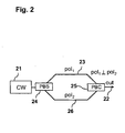
- Fig. 2 is a schematic representation of the application of a conventional depolarization technique.
- Fig 2 shows the combination 22 of two orthogonally polarized CW signals 23 and 26 from a single laser source 21. It shows also the Polarization Beam Splitter PBS 24, which splits the single laser source 21 in two orthogonally polarized CW signals 23 and 26, and a Polarization Beam Combiner PBC 25, which combines the two orthogonally polarized CW signals 23 and 26.
- Fig. 3 is a representation 31 of the degradation of the Bit Error Ratio BER 32 of a 40G CP-QPSK optical signal due to a depolarized CW channel.
- Fig 3 shows the Bit Error Ratio BER 32 of a 40G CP-QPSK optical signal versus the difference between the power of the Continuous Wave CW pump signal and the power of CP-QPSK optical signal for three different cases:
- the CW pump and 40G CP-QPSK co-propagate over a 700 km fiber link.
- the CW power level has been continuously increased relatively to the data signal.
- significant bit-error ratio degradations in the CP-QPSK signal can be observed starting at power differences of 1 dB.
- FEC threshold of 10 -3 is violated when exceeding 5 dB pump-data power difference.
- significant distortions have been detected even when the CW signal is located 2.5THz away from the CP-QPSK channel.
- a conventional depolarized CW signal causes significant penalties for polarization multiplexed data signals over a very wide spectral region, whose width depends on the power of the CW signal itself. For this reason, due to high power difference, similar distortions can be expected also from co-propagating Raman pumps, thus strongly limiting its application in optical transmission systems with polarization-multiplexed channels.
- ASE Amplified Spontaneous Emission
- Fig. 4 is a representation 41 of the degradation of the Bit Error Ratio BER 42 of a 40G CP-QPSK optical signal due to a Amplified Spontaneous Emission (ASE) source.
- Fig 4 shows the Bit Error Ratio BER 42 of a 40G CP-QPSK optical signal versus the difference between the power of the Amplified Spontaneous Emission (ASE) source and the power of CP-QPSK optical signal for three different cases:
- Cross polarization modulation effects are expected to affect not only standard coherent receivers based on digital signal processing, but also direct-detection receivers employing fast polarization controllers for input polarization demultiplexing. Indeed, current active polarization controllers can compensate only relatively slow polarization rotations (in the order of a hundred kHz) but would not be able to cope with fast polarization rotations induced by Cross Polarization Modulation (XPolM).
- XPolM Cross Polarization Modulation
- the problem to be solved is to overcome the disadvantages stated above and in particular to provide a solution that minimize the destructive Cross Polarization Modulation (XPolM) interactions in polarization-multiplexed transmission systems such as CP-QPSK.
- XPolM Cross Polarization Modulation
- an optical communication system for transmitting an optical signal, comprising a pump source configured to generate a pump signal having rotating polarization, a polarization sensitive receiver for receiving the optical signal having a polarization tracking cut-off frequency, wherein the polarization of the pump signal is configured to rotate at a predetermined frequency of polarization rotation and the frequency of polarization rotation of the pump signal is higher than the polarization tracking cut-off frequency of the receiver.
- the polarization tracking cut-off frequency can be defined as a frequency of polarization variations that leads to factor of two higher BER at the polarization sensitive receiver comparing to case without.
- the optical signal is a coherently-detected polarization-multiplexed quadrature phase shift keying (CP-QPSK) signal.
- CP-QPSK coherently-detected polarization-multiplexed quadrature phase shift keying
- system further comprises a continuous wave (CW) laser source for generating a continuous wave (CW) laser signal.
- CW continuous wave
- the system further comprises a polarization modulator for modulating the continuous wave (CW) laser signal and a radio frequency (RF) source connected with the polarization modulator for generating the polarization rotation of the pump signal.
- a polarization modulator for modulating the continuous wave (CW) laser signal
- RF radio frequency
- the system further comprises a first polarization rotator for rotating the polarization of the continuous wave (CW) laser signal and thereby generating a first component of the pump signal.
- CW continuous wave
- the system further comprises an optical phase modulator for phase-modulating the continuous wave (CW) laser signal and a radio frequency (RF) source connected with the phase modulator, the optical phase modulator being configured to generate a second component of the pump signal.
- CW continuous wave
- RF radio frequency
- the pump signal is a combination of the first component and the second component of the pump signal.
- first component and the second component of the pump signal have a different polarization with respect to each other.
- the radio frequency (RF) source is configured to adjust the frequency of polarization rotation of the pump signal.
- the system further comprises a first continuous wave (CW) laser source for generating a first continuous wave laser signal and a second continuous wave (CW) laser source for generating a second continuous wave (CW) laser signal, the first and the second continuous wave (CW) laser signals being frequency detuned with respect to each other.
- CW continuous wave
- CW continuous wave
- system further comprises a second polarization rotator coupled with the second continuous wave (CW) laser source for rotating the polarization of the second continuous wave (CW) laser signal and thereby generating a second laser signal.
- CW continuous wave
- the pump signal is a combination of the first continuous wave (CW) laser signal and the second laser signal, the first continuous wave (CW) laser signal and the second laser signal having a different polarization with respect to each other.
- the frequency of polarization rotation of the pump signal is adjustable by adjusting the frequency detuning of the first and the second continuous wave (CW) laser signals with respect to each other.
- the apparatus further includes an optical fiber link for propagating the pump signal and the optical signal.
- the polarization sensitive receiver is a coherent receiver.
- a method for transmitting an optical signal which includes: generating a pump signal having rotating polarization, transmitting the pump signal, transmitting the optical signal, receiving the optical signal by means of a polarization sensitive receiver having a polarization tracking cut-off frequency, rotating the polarization of the pump signal at a predetermined frequency of polarization rotation, the frequency of polarization rotation of the pump signal being higher than the polarization tracking cut-off frequency of the receiver.
- Fig. 5 is a schematic representation of the application of a depolarization technique for application in polarization-multiplexed transmission system according to an embodiment of the invention.
- a pump source 51 for example a Raman pump source, which includes a single CW light source 53, for example a laser source.
- the CW light source 53 generates a CW laser signal 56 which is modulated by a polarization modulator 55, in particular a fast polarization modulator, that generates the fast polarization rotation of the pump signal 52.
- the required speed of polarization rotations can be generated using the RF source 54, connected to the polarization modulator 55, which is configured to adjust the frequency of polarization rotation of the pump signal 52.
- the so generated pump signal 52 can be propagated in a fiber link together with an optical signal, for example a CP-QPSK signal.
- the optical signal and the pump signal 52 can be received by a polarization sensitive receiver having a given polarization tracking cut-off frequency.
- the ultra-fast polarization of the pump signal 52 can be adjusted in such a way that the frequency of polarization rotation of the pump signal 52 is higher than the polarization tracking cut-off frequency of the receiver.
- the spectral components of the polarization rotation can be naturally rejected by the polarization sensitive receiver, which may also be a coherent receiver.
- the polarization tracking cut-off frequency can be defined as a frequency of polarization variations that leads to factor of two higher BER at the polarization sensitive receiver comparing to case without. In this way the destructive Cross Polarization Modulation (XPolM) interactions in polarization-multiplexed transmission systems can be efficiently minimized.
- XPolM Cross Polarization Modulation
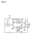
- Fig. 6 is a schematic representation of the application of a depolarization technique for application in polarization-multiplexed transmission system according to an embodiment of the invention.
- a pump source 61 for example a Raman pump source, which generates a pump signal 62, combination of a phase modulated component 68 and a phase un-modulated component 67, having different polarization, derived from a single CW laser source 63.
- An optical coupler for example a 3dB coupler (not shown in Figure 6 ) may split the single laser source 63 in two differently polarized CW signals 623 and 626. According to a different embodiment of the invention, the two CW signals 623 and 626 may be orthogonally polarized.
- An optical phase modulator 66 phase-modulates the CW signals 626, while a polarization rotator 65, rotates the polarization of the CW signal 623 relative to the CW signal 626.
- An optical coupler for example a 3dB coupler (not shown in Figure 6 ), may combine the two differently polarized CW signals 67 and 68.
- the required speed of polarization rotations can be generated using the RF source 64, connected to the optical phase modulator 66, which is configured to adjust the frequency of polarization rotation of the pump signal 62.
- the so generated pump signal 62 can be propagated in a fiber link together with an optical signal, for example a CP-QPSK signal.
- the optical signal and the pump signal 62 can be received by a polarization sensitive receiver having a polarization tracking cut-off frequency.
- the ultra-fast polarization of the pump signal 62 can be adjusted in such a way that the frequency of polarization rotation of the pump signal 62 is higher than the polarization tracking cut-off frequency of the receiver.
- the spectral components of the polarization rotation can be naturally rejected by the polarization sensitive receiver, which may also be a coherent receiver. In this way the destructive Cross Polarization Modulation (XPolM) interactions in polarization-multiplexed transmission systems can be efficiently minimized.
- XPolM destructive Cross Polarization Modulation
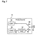
- Fig. 7 is a schematic representation of the application of a depolarization technique for application in polarization-multiplexed transmission system according to an embodiment of the invention.
- Fig 7 shows a pump source 71, for example a Raman pump source, which generates pump signal 72, combination of two frequency detuned, differently polarized CW laser signals 75 and 78 from two CW laser sources 73 and 74.
- the two CW signals 75 and 78 may be orthogonally polarized.
- a polarization rotator 77 coupled with the second continuous wave (CW) laser source 74, which rotates the polarization of the continuous wave (CW) laser signal 76 relative to the CW signal 75 thereby generating the CW signal 78.
- the fast polarization rotation is generated by combining the two laser signal 78 and 75.
- the frequency of polarization rotation of the pump signal 72 can be adjustable by adjusting the frequency detuning of the first 75 and the second 76 continuous wave (CW) laser signals with respect to each other.
- speed of polarization rotation is directly related to the frequency detuning of the two CW channels.
- the so generated pump signal 72 can be propagated in an fiber link together with an optical signal, for example a CP-QPSK signal.
- the optical signal and the pump signal 72 can be received by a polarization sensitive receiver having a polarization tracking cut-off frequency.
- the ultra-fast polarization of the pump signal 72 can be adjusted in such a way that the frequency of polarization rotation of the pump signal 72 is higher than the polarization tracking cut-off frequency of the receiver.
- the spectral components of the polarization rotation can be naturally rejected by the polarization sensitive receiver, which may also be a coherent receiver. In this way the destructive Cross Polarization Modulation (XPolM) interactions in polarization-multiplexed transmission systems can be efficiently minimized.
- XPolM destructive Cross Polarization Modulation
- the embodiment of the invention comprising the two detuned CW laser signal 75 and 78 does not require necessarily the employment of high RF electronics; furthermore, it provides a benefit related to power budget, mechanical footprint as well as cost efficiency.
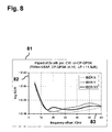
- Fig. 8 is a representation 81 of the degradation of the Bit Error Ratio BER 82 of a 40G CP-QPSK optical signal due to two orthogonally polarized, frequency detuned CW laser sources.
- Fig 8 shows the Bit Error Ratio BER 82 of a 40G CP-QPSK optical signal versus the frequency offset 83 between the two orthogonally polarized, frequency detuned CW laser sources.
- the 40G CP-QPSK receiver is characterized by a polarization tracking cut-off frequency of around 8 GHz.
- Fig. 9 is a representation 91 of the degradation of the Bit Error Ratio BER 92 of a 40G CP-QPSK optical signal due to two orthogonally polarized, frequency detuned CW laser sources.
- Fig 9 shows the Bit Error Ratio BER 92 of a 40G CP-QPSK optical signal versus the spacing 93 between the CW pump signal and the CP-QPSK signal.
- Fig. 9 shows that a frequency offset ⁇ f of 15 GHz between the two CW signals leads to distortion-free performance almost independently of the spacing between the CW pump and the CP-QPSK channel.
- the present invention allows for generic usage of optical pump sources independently on modulation format of data channels.
- a critical minimum frequency detuning For each modulation format and data rate, a critical minimum frequency detuning has to be identified individually. Theoretically, a fix value for the maximum frequency detuning cannot be established. Larger frequency offset may be beneficial for reducing of pump beating, however this may reduce the optical bandwidth available for useful channels' transmission and may leads to higher sensitivity to frequency dependent polarization changes (due to second order polarization mode dispersion, SOPMD or polarization dependent loss, PDL).
- SOPMD second order polarization mode dispersion
- PDL polarization dependent loss
- CW sources fixed laser with wavelength locker or a tunable laser can be used.
- the two CW lights have to be combined at different polarizations (preferably orthogonally polarized).
- the power level of the lasers should preferably be similar, but slight mismatches do not affect the performance significantly.
Abstract
Description
- The invention refers to a system and a method for signal processing in a communication system (e.g. an optical communication system).
- Driven by growing demand on transmission capacities, sophisticated modulation formats with improved spectral efficiency are becoming the established technology-of-choice for commercial usage in optical communication systems.
- Relatively robust and price effective on-off keying, widely applied for data rates of up to 10 Gbit/s, is step by step replaced by transmission formats modulated in phase and polarization, enabling further increase of data rates to 40 Gbit/s, 100 Gbit/s and higher.
- Hereto, combination of polarization multiplexing and coherent signal detection, namely "coherently-detected polarization-multiplexed quadrature phase shift keying" (CP-QPSK), has been identified as a modulation format of choice for next generation high capacity transmission.
- The main CP-QPSK drivers are that it doubles the spectral efficiency and the total capacity, it is part of the 100G standardization according to the Optical Internetworking Forum (OIF), and all major system houses and component suppliers are currently working on CP-QPSK solutions.
- On system level, it is of interest to reuse already implemented concepts when introducing new modulation formats.
- This applies also for optical pump sources that are currently used in context with different applications.
- As an example of applications for optical pump sources it is worthwhile to mention high power pump lasers for Raman amplifiers, which enable a further increase of span length or idler channels which guarantee optimum EDFA operation in Dense Wavelength Division Multiplexing (DWDM) systems with limited total channel count as well as link stabilization in submarine transmission systems, or dynamically controlled Continuous Wave (CW) channels, which allow for network stabilization in case of sudden power transients (e.g. due to fiber cut).
- In all of the aforementioned applications, the power level of the pump signal is usually higher than the average power level of the in-service data signals. In order to prevent polarization dependent gain ripple or signal distortions due to FWM interactions or polarization-dependent Raman gain, an unpolarized CW light or a filtered ASE source is conventionally employed.
- In the European patent application
EP 1315321 "Pump source including polarization scrambling in Raman amplified optical WDM systems" a pump source including a polarization scrambler is proposed to reduce the effects of polarization dependent gain. - Further in the patent application
US 5345331 A "Technique for reducing polarization dependent gain in an amplified optical transmission system" a pump source arrangement is disclosed, wherein the pump laser coupled to a passive polarization scrambler to reduce the effects of polarization dependent gain. - All these techniques are well known in the art and used in current Dense Wavelength Division Multiplexing (DWDM) systems with conventional modulation formats as, for example, On Off Keying (OOK), Optical Duo Binary (ODB), Differential Phase Shift Keying. (DPSK) or Differential Quadrature Phase Shift Keying (DQPSK).
- However, much more than other modulation formats, modulation formats based on polarization multiplexing are sensitive to random or deterministic polarization rotations induced by cross-polarization modulation (XPolM) between the optical signals propagating along a transmission link.
- In particular, a critical role is played by the spectral region in which such polarization rotations fall. Accordingly, the following classification can be introduced:
- Slow polarization rotations, whose spectral components fall within the adaptive compensation speed of the receiver (< 100 kHz). These rotations are typically caused by mechanical and thermal stress effects cumulating during fiber propagation and the receiver is designed to fully compensate for them.
- Fast polarization rotations, whose spectral components exceed the adaptive compensation speed of the receiver but fall within its electrical bandwidth (between 100 kHz and the polarization tracking cut-off frequency). These polarization rotations result from XPolM effects cumulating during fiber propagation and the adaptive algorithms within the receiver are not fast enough to compensate for them.
- Ultra-fast polarization rotations, whose spectral components fall outside the electrical bandwidth of the receiver (above the polarization tracking cut-off frequency). These polarization rotations also result from XPolM effects cumulating during fiber propagation, but they are so fast that they are rejected by the electrical filter of the receiver and therefore must not be compensated for by the adaptive algorithms of the receiver itself.
-
Fig. 1 is a schematic representation of the application of a conventional depolarization technique. In particular,Fig 1 shows a combination of two delayed fractions of asingle CW light 11, the first fraction over a VariableOptical Attenuator 14 and the second fraction over anoptical fiber 13 characterized by a fiber length L > Lcoh, where Lcoh is the coherence length. -
Fig. 2 is a schematic representation of the application of a conventional depolarization technique. In particular,Fig 2 shows thecombination 22 of two orthogonally polarizedCW signals single laser source 21. It shows also the Polarization Beam Splitter PBS 24, which splits thesingle laser source 21 in two orthogonally polarizedCW signals CW signals -
Fig. 3 is arepresentation 31 of the degradation of the BitError Ratio BER 32 of a 40G CP-QPSK optical signal due to a depolarized CW channel. In particular,Fig 3 shows the BitError Ratio BER 32 of a 40G CP-QPSK optical signal versus the difference between the power of the Continuous Wave CW pump signal and the power of CP-QPSK optical signal for three different cases: - a
combination 34 of two delayed fractions of a single CW light, the CW signal being located 50GHz away from the CP-QPSK optical signal; - a
combination 35 of two orthogonally polarized CW signals and from a single laser source, the CW signal being located 50GHz away from the CP-QPSK optical signal; - a
combination 36 of two orthogonally polarized CW signals and from a single laser source, the CW signal being located 2.6THz away from the CP-QPSK optical signal. - In the example, the CW pump and 40G CP-QPSK co-propagate over a 700 km fiber link. The CW power level has been continuously increased relatively to the data signal. As shown in
Fig. 3 , significant bit-error ratio degradations in the CP-QPSK signal can be observed starting at power differences of 1 dB. When the CW signal is a direct neighbor of the CP-QPSK data signal FEC threshold of 10-3 is violated when exceeding 5 dB pump-data power difference. Furthermore, significant distortions have been detected even when the CW signal is located 2.5THz away from the CP-QPSK channel. - The example represented in
Fig. 3 clearly shows that a conventional depolarized CW signal causes significant penalties for polarization multiplexed data signals over a very wide spectral region, whose width depends on the power of the CW signal itself. For this reason, due to high power difference, similar distortions can be expected also from co-propagating Raman pumps, thus strongly limiting its application in optical transmission systems with polarization-multiplexed channels. - As an alternative, the use of filtered Amplified Spontaneous Emission (ASE) light has been investigated. In contrary to intentionally depolarized CW signals characterized by fast but deterministic polarization rotations, ASE light is completely depolarized, therefore polarization rotations are completely randomized and all polarization states are represented in it with the same probability.
-
Fig. 4 is arepresentation 41 of the degradation of the BitError Ratio BER 42 of a 40G CP-QPSK optical signal due to a Amplified Spontaneous Emission (ASE) source. In particular,Fig 4 shows the BitError Ratio BER 42 of a 40G CP-QPSK optical signal versus the difference between the power of the Amplified Spontaneous Emission (ASE) source and the power of CP-QPSK optical signal for three different cases: - the Amplified Spontaneous Emission (ASE) source is located 350GHz away 44 from the CP-QPSK optical signal;
- the Amplified Spontaneous Emission (ASE) source is located 850GHz away 45 from the CP-QPSK optical signal;
- the Amplified Spontaneous Emission (ASE) source is located 2.60THz away 46 from the CP-QPSK optical signal.
- For this experiment, a wide-band, Amplified Spontaneous Emission (ASE) source filtered by two cascaded 50 GHz optical band-pass filters has been co-propagated together with a 40G CP-QPSK signal over a 700 km fiber link, and the bit-error ratio of the data signal has been measured for different delta power values. As shown in
Fig. 4 , significant bit-error rate degradations of CP-QPSK signal over a large spectral region could be observed when increasing the power of the ASE source. This is due to the fact that the Cross Polarization Modulation (XPolM) induced random polarization rotations cover all of the above-mentioned categories: slow, fast and ultra fast. In this case, the fast polarization rotations were responsible for the observed impairment. - Cross polarization modulation effects are expected to affect not only standard coherent receivers based on digital signal processing, but also direct-detection receivers employing fast polarization controllers for input polarization demultiplexing. Indeed, current active polarization controllers can compensate only relatively slow polarization rotations (in the order of a hundred kHz) but would not be able to cope with fast polarization rotations induced by Cross Polarization Modulation (XPolM).
- A large number o idler channels schemes, as well as transient suppression channels schemes based either on polarized/depolarized CW signals or on filtered ASE sources are known from the prior art. Cited, for example, is C. Headley, G. Agraval, "Raman Amplification in Fiber Optics Communication Systems" Academic Press, December 30, 2004 , or J. Chesnoy, G. Agrawal, I. P. Kaminow, and P. Kelley, "Undersea Fiber Communication Systems" Academic Press, October 3 .
- However, such conventional schemes have a severe impact on next generation transmission systems based on coherently-detected polarization-multiplexed optical signals such as CP-QPSK.
- The problem to be solved is to overcome the disadvantages stated above and in particular to provide a solution that minimize the destructive Cross Polarization Modulation (XPolM) interactions in polarization-multiplexed transmission systems such as CP-QPSK.
- In order to overcome the above-described need in the art, the present invention discloses an optical communication system for transmitting an optical signal, comprising a pump source configured to generate a pump signal having rotating polarization, a polarization sensitive receiver for receiving the optical signal having a polarization tracking cut-off frequency, wherein the polarization of the pump signal is configured to rotate at a predetermined frequency of polarization rotation and the frequency of polarization rotation of the pump signal is higher than the polarization tracking cut-off frequency of the receiver.
- The polarization tracking cut-off frequency can be defined as a frequency of polarization variations that leads to factor of two higher BER at the polarization sensitive receiver comparing to case without.
- In a next embodiment of the invention the optical signal is a coherently-detected polarization-multiplexed quadrature phase shift keying (CP-QPSK) signal.
- It is also an embodiment, that the system further comprises a continuous wave (CW) laser source for generating a continuous wave (CW) laser signal.
- In other alternative embodiments of the present invention, the system further comprises a polarization modulator for modulating the continuous wave (CW) laser signal and a radio frequency (RF) source connected with the polarization modulator for generating the polarization rotation of the pump signal.
- In a further embodiment, the system further comprises a first polarization rotator for rotating the polarization of the continuous wave (CW) laser signal and thereby generating a first component of the pump signal.
- In a next embodiment, the system further comprises an optical phase modulator for phase-modulating the continuous wave (CW) laser signal and a radio frequency (RF) source connected with the phase modulator, the optical phase modulator being configured to generate a second component of the pump signal.
- In an alternative embodiment, the pump signal is a combination of the first component and the second component of the pump signal.
- It is also an embodiment, that the first component and the second component of the pump signal have a different polarization with respect to each other.
- In other alternative embodiments of the present invention, the radio frequency (RF) source is configured to adjust the frequency of polarization rotation of the pump signal.
- In a further embodiment, the system further comprises a first continuous wave (CW) laser source for generating a first continuous wave laser signal and a second continuous wave (CW) laser source for generating a second continuous wave (CW) laser signal, the first and the second continuous wave (CW) laser signals being frequency detuned with respect to each other.
- In a next embodiment, the system further comprises a second polarization rotator coupled with the second continuous wave (CW) laser source for rotating the polarization of the second continuous wave (CW) laser signal and thereby generating a second laser signal.
- In an alternative embodiment, the pump signal is a combination of the first continuous wave (CW) laser signal and the second laser signal, the first continuous wave (CW) laser signal and the second laser signal having a different polarization with respect to each other.
- It is also an embodiment, that the frequency of polarization rotation of the pump signal is adjustable by adjusting the frequency detuning of the first and the second continuous wave (CW) laser signals with respect to each other.
- In a further embodiment, the apparatus further includes an optical fiber link for propagating the pump signal and the optical signal.
- In an alternative embodiment, the polarization sensitive receiver is a coherent receiver.
- The problem stated above is also solved by a method for transmitting an optical signal which includes: generating a pump signal having rotating polarization, transmitting the pump signal, transmitting the optical signal, receiving the optical signal by means of a polarization sensitive receiver having a polarization tracking cut-off frequency, rotating the polarization of the pump signal at a predetermined frequency of polarization rotation, the frequency of polarization rotation of the pump signal being higher than the polarization tracking cut-off frequency of the receiver.
- The method, the apparatus and the system provided, in particular, bears the following advantages:
- a) They minimize the destructive Cross Polarization Modulation (XPolM) interactions in polarization-multiplexed transmission systems such as CP-QPSK.
- b) They allow the generic usage of optical pump sources independently on modulation format of data channels.
- c) They do not require necessarily the employment of high RF electronics.
- d) They are easy to implement.
- e) They provide a benefit related to power budget, mechanical footprint as well as cost efficiency.
- The invention is explained by way of example in more detail below with the aid of the attached drawings.
-
Fig. 1 is a schematic representation of the application of a conventional depolarization technique. -
Fig. 2 is a schematic representation of the application of a conventional depolarization technique. -
Fig. 3 is arepresentation 31 of the degradation of the BitError Ratio BER 32 of a 40G CP-QPSK optical signal due to a depolarized CW channel. -
Fig. 4 is arepresentation 41 of the degradation of the BitError Ratio BER 42 of a 40G CP-QPSK optical signal due to an Amplified Spontaneous Emission (ASE) source. -
Fig. 5 is a schematic representation of the application of a depolarization technique for application in polarization-multiplexed transmission system according to an embodiment of the invention. -
Fig. 7 is a schematic representation of the application of a depolarization technique for application in polarization-multiplexed transmission system according to an embodiment of the invention. -
Fig. 8 is arepresentation 81 of the degradation of the BitError Ratio BER 82 of a 40G CP-QPSK optical signal due to two orthogonally polarized, frequency detuned CW laser sources. -
Fig. 9 is arepresentation 91 of the degradation of the BitError Ratio BER 92 of a 40G CP-QPSK optical signal due to two orthogonally polarized, frequency detuned CW laser sources. - As regards the description of
Figures 1 to 4 , reference is made to the background of the invention. - Illustrative embodiments will now be described with reference to the accompanying drawings to disclose the teachings of the present invention. While the present invention is described herein with reference to illustrative embodiments for particular applications, it should be understood that the invention is not limited thereto. Those having ordinary skill in the art and access to the teachings provided herein will recognize additional modifications, applications, and embodiments within the scope thereof and additional fields in which the present invention would be of significant utility.
-
Fig. 5 is a schematic representation of the application of a depolarization technique for application in polarization-multiplexed transmission system according to an embodiment of the invention. In particular,Fig 5 shows apump source 51, for example a Raman pump source, which includes a single CWlight source 53, for example a laser source. The CWlight source 53 generates aCW laser signal 56 which is modulated by apolarization modulator 55, in particular a fast polarization modulator, that generates the fast polarization rotation of thepump signal 52. The required speed of polarization rotations can be generated using theRF source 54, connected to thepolarization modulator 55, which is configured to adjust the frequency of polarization rotation of thepump signal 52. The so generatedpump signal 52 can be propagated in a fiber link together with an optical signal, for example a CP-QPSK signal. The optical signal and thepump signal 52 can be received by a polarization sensitive receiver having a given polarization tracking cut-off frequency. The ultra-fast polarization of thepump signal 52 can be adjusted in such a way that the frequency of polarization rotation of thepump signal 52 is higher than the polarization tracking cut-off frequency of the receiver. As a consequence, the spectral components of the polarization rotation can be naturally rejected by the polarization sensitive receiver, which may also be a coherent receiver. The polarization tracking cut-off frequency can be defined as a frequency of polarization variations that leads to factor of two higher BER at the polarization sensitive receiver comparing to case without. In this way the destructive Cross Polarization Modulation (XPolM) interactions in polarization-multiplexed transmission systems can be efficiently minimized. -
Fig. 6 is a schematic representation of the application of a depolarization technique for application in polarization-multiplexed transmission system according to an embodiment of the invention. In particular,Fig 6 shows apump source 61, for example a Raman pump source, which generates apump signal 62, combination of a phase modulatedcomponent 68 and a phase un-modulated component 67, having different polarization, derived from a singleCW laser source 63. An optical coupler, for example a 3dB coupler (not shown inFigure 6 ) may split thesingle laser source 63 in two differently polarized CW signals 623 and 626. According to a different embodiment of the invention, the twoCW signals optical phase modulator 66, phase-modulates the CW signals 626, while apolarization rotator 65, rotates the polarization of the CW signal 623 relative to theCW signal 626. An optical coupler, for example a 3dB coupler (not shown inFigure 6 ), may combine the two differently polarized CW signals 67 and 68. The required speed of polarization rotations can be generated using theRF source 64, connected to theoptical phase modulator 66, which is configured to adjust the frequency of polarization rotation of thepump signal 62. The so generatedpump signal 62 can be propagated in a fiber link together with an optical signal, for example a CP-QPSK signal. The optical signal and thepump signal 62 can be received by a polarization sensitive receiver having a polarization tracking cut-off frequency. The ultra-fast polarization of thepump signal 62 can be adjusted in such a way that the frequency of polarization rotation of thepump signal 62 is higher than the polarization tracking cut-off frequency of the receiver. As a consequence, the spectral components of the polarization rotation can be naturally rejected by the polarization sensitive receiver, which may also be a coherent receiver. In this way the destructive Cross Polarization Modulation (XPolM) interactions in polarization-multiplexed transmission systems can be efficiently minimized. -
Fig. 7 is a schematic representation of the application of a depolarization technique for application in polarization-multiplexed transmission system according to an embodiment of the invention. In particular,Fig 7 shows apump source 71, for example a Raman pump source, which generatespump signal 72, combination of two frequency detuned, differently polarized CW laser signals 75 and 78 from twoCW laser sources polarization rotator 77, coupled with the second continuous wave (CW)laser source 74, which rotates the polarization of the continuous wave (CW)laser signal 76 relative to the CW signal 75 thereby generating theCW signal 78. The fast polarization rotation is generated by combining the twolaser signal 78 and 75. The frequency of polarization rotation of thepump signal 72 can be adjustable by adjusting the frequency detuning of the first 75 and the second 76 continuous wave (CW) laser signals with respect to each other. Hereto, speed of polarization rotation is directly related to the frequency detuning of the two CW channels. - The so generated
pump signal 72 can be propagated in an fiber link together with an optical signal, for example a CP-QPSK signal. The optical signal and thepump signal 72 can be received by a polarization sensitive receiver having a polarization tracking cut-off frequency. The ultra-fast polarization of thepump signal 72 can be adjusted in such a way that the frequency of polarization rotation of thepump signal 72 is higher than the polarization tracking cut-off frequency of the receiver. As a consequence, the spectral components of the polarization rotation can be naturally rejected by the polarization sensitive receiver, which may also be a coherent receiver. In this way the destructive Cross Polarization Modulation (XPolM) interactions in polarization-multiplexed transmission systems can be efficiently minimized. - The embodiment of the invention comprising the two detuned
CW laser signal 75 and 78 does not require necessarily the employment of high RF electronics; furthermore, it provides a benefit related to power budget, mechanical footprint as well as cost efficiency. -
Fig. 8 is arepresentation 81 of the degradation of the BitError Ratio BER 82 of a 40G CP-QPSK optical signal due to two orthogonally polarized, frequency detuned CW laser sources. - In particular,
Fig 8 shows the BitError Ratio BER 82 of a 40G CP-QPSK optical signal versus the frequency offset 83 between the two orthogonally polarized, frequency detuned CW laser sources. - The 40G CP-QPSK receiver is characterized by a polarization tracking cut-off frequency of around 8 GHz.
- For frequency offset below 10 GHz, significant degradations of data signal can be observed when co-propagating with the pump in a fiber link (optical power variation ΔP = 11.5 dB). However once the frequency offset is larger than a critical minimum detuning (in the example shown in
Fig. 8 ca. 12 GHz), the distorting influence of the high power pump signal is effectively suppressed. -
Fig. 9 is arepresentation 91 of the degradation of the BitError Ratio BER 92 of a 40G CP-QPSK optical signal due to two orthogonally polarized, frequency detuned CW laser sources. - In particular,
Fig 9 shows the BitError Ratio BER 92 of a 40G CP-QPSK optical signal versus thespacing 93 between the CW pump signal and the CP-QPSK signal. - Moreover,
Fig. 9 shows that a frequency offset Δf of 15 GHz between the two CW signals leads to distortion-free performance almost independently of the spacing between the CW pump and the CP-QPSK channel. - The experimental analysis confirmed that a minimum frequency detuning (polarization rotation speed) is required in order to effectively suppress impairments on polarization multiplexed data signals. Thus, controlled frequency spacing between the two CW lasers may be needed.
- The present invention allows for generic usage of optical pump sources independently on modulation format of data channels.
- For each modulation format and data rate, a critical minimum frequency detuning has to be identified individually. Theoretically, a fix value for the maximum frequency detuning cannot be established. Larger frequency offset may be beneficial for reducing of pump beating, however this may reduce the optical bandwidth available for useful channels' transmission and may leads to higher sensitivity to frequency dependent polarization changes (due to second order polarization mode dispersion, SOPMD or polarization dependent loss, PDL).
- As far as the CW sources are concerned, fixed laser with wavelength locker or a tunable laser can be used. The two CW lights have to be combined at different polarizations (preferably orthogonally polarized). The power level of the lasers should preferably be similar, but slight mismatches do not affect the performance significantly.
- The present invention is not limited to the details of the above described principles. The scope of the invention is defined by the appended claims and all changes and modifications as fall within the equivalents of the scope of the claims are therefore to be embraced by the invention. Mathematical conversions or equivalent calculations of the signal values based on the inventive method or the use of analogue signals instead of digital values are also incorporated.
-
- ASE
- Amplified Spontaneous Emission
- BER
- Bit Error Ratio
- CW
- Continuous Wave
- CP-QPSK
- Coherent Polarization-multiplexed Quadrature Phase Shift Keying
- DPSK
- Differential Phase Shift Keying
- DQPSK
- Differential Quadrature Phase Shift Keying
- DWDM
- Dense Wavelength Division Multiplexing
- EDFA
- Erbium Doped Fiber Amplifier
- FWM
- Four Wave Mixing
- ODB
- Optical Duo Binary
- OIF
- Optical Internetworking Forum
- OOK
- On Off Keying
- OTSC
- Optical Transient Suppression for C-band
- OSA
- Optical Spectrum Analyzer
- PBC
- Polarization Beam Combiner
- PBS
- Polarization Beam Splitter
- PDL
- Polarization Dependent Loss
- SOPMD
- Second Order Polarization Mode Dispersion
- VOA
- Variable Optical Attenuator
- XPolM
- Cross Polarization Modulation
Claims (15)
- An arrangement for transmitting an optical signal comprising:a pump source (51, 61, 71) configured to generate a pump signal (52, 62, 72) having rotating polarization;a polarization sensitive receiver for receiving the optical signal having a polarization tracking cut-off frequency which is defined as a frequency of polarization variations that leads to factor of two higher BER at the polarization sensitive receiver compared to case without;characterized in that:the polarization of the pump signal (52, 62, 72) is configured to rotate at a predetermined frequency of polarization rotation;the frequency of polarization rotation of the pump signal (52, 62, 72) is higher than the polarization tracking cut-off frequency of the receiver.
- A system according to claim 1, the system further comprising a continuous wave (CW) laser source (53, 63) for generating a continuous wave (CW) laser signal.
- A system according to claim 2, the system further comprising a polarization modulator (55) for modulating the continuous wave (CW) laser signal and a radio frequency (RF) source (54) connected with the polarization modulator (55) for generating the polarization rotation of the pump signal.
- A system according to claim 2, the system further comprising a first polarization rotator (65) for rotating the polarization of the continuous wave (CW) laser signal and thereby generating a first component (67) of the pump signal (62).
- A system according to claim 4, the system further comprising an optical phase modulator (66) for phase-modulating the continuous wave (CW) laser signal and a radio frequency (RF) source (64) connected with the phase modulator (66), the optical phase modulator (66) being configured to generate a second component (68) of the pump signal (62).
- A system according to claim 5, the pump signal (62) being a combination of the first component (67) and the second component (68) of the pump signal (62).
- A system according to claim 6, the first component (67) and the second component (68) of the pump signal (62) having a different polarization with respect to each other.
- A system as claimed in claim 3 or in any of the claims from 5 to 7, wherein the radio frequency (RF) source (54, 64) is configured to adjust the frequency of polarization rotation of the pump signal (52, 62).
- A system according to claim 1, the system further comprising a first continuous wave (CW) laser source (73) for generating a first continuous wave (CW) laser signal (75) and a second continuous wave (CW) laser source (74) for generating a second continuous wave (CW) laser signal (76), the first (75) and the second (76) continuous wave (CW) laser signals being frequency detuned with respect to each other.
- A system according to claim 8, the system further comprising a second polarization rotator (77) coupled with the second continuous wave (CW) laser source (74) for rotating the polarization of the second continuous wave (CW) laser signal (76) and thereby generating a second laser signal (78).
- A system according to claim 10, the pump signal (72) being a combination of the first continuous wave (CW) laser signal (75) and the second laser signal (78), the first continuous wave (CW) laser signal (75) and the second laser signal (78) having a different polarization with respect to each other.
- A system as claimed in any of the claims from 9 to 11, wherein the frequency of polarization rotation of the pump signal (72) is adjustable by adjusting the frequency detuning of the first (75) and the second (76) continuous wave (CW) laser signals with respect to each other.
- A system as claimed in any of the preceding claims, further including an optical fiber link for propagating the pump signal (52, 62, 72) and the optical signal.
- A system as claimed in any of the preceding claims, the polarization sensitive receiver being a coherent receiver.
- A method for transmitting an optical signal comprising:generating a pump signal (52, 62, 72) having rotating polarization;transmitting the optical signal;transmitting the pump signal (52, 62, 72);receiving the optical signal by means of a polarization sensitive receiver having a polarization tracking cut-off frequency which is defined as a frequency of polarization variations that leads to factor of two higher BER at the polarization sensitive receiver compared to case without;characterized in that:rotating the polarization of the pump signal (52, 62, 72) at a predetermined frequency of polarization rotation, the frequency of polarization rotation of the pump signal (52, 62, 72) being higher than the polarization tracking cut-off frequency of the receiver.
Priority Applications (4)
| Application Number | Priority Date | Filing Date | Title |
|---|---|---|---|
| EP10192953.7A EP2458751B1 (en) | 2010-11-29 | 2010-11-29 | Optical communication system and method |
| US13/990,371 US9490930B2 (en) | 2010-11-29 | 2011-11-28 | Optical communication system and method |
| PCT/EP2011/071110 WO2012072534A1 (en) | 2010-11-29 | 2011-11-28 | Optical communication system and method |
| CN201180066212.4A CN103329461B (en) | 2010-11-29 | 2011-11-28 | Optical communication system and method |
Applications Claiming Priority (1)
| Application Number | Priority Date | Filing Date | Title |
|---|---|---|---|
| EP10192953.7A EP2458751B1 (en) | 2010-11-29 | 2010-11-29 | Optical communication system and method |
Publications (2)
| Publication Number | Publication Date |
|---|---|
| EP2458751A1 EP2458751A1 (en) | 2012-05-30 |
| EP2458751B1 true EP2458751B1 (en) | 2013-11-20 |
Family
ID=43877062
Family Applications (1)
| Application Number | Title | Priority Date | Filing Date |
|---|---|---|---|
| EP10192953.7A Active EP2458751B1 (en) | 2010-11-29 | 2010-11-29 | Optical communication system and method |
Country Status (4)
| Country | Link |
|---|---|
| US (1) | US9490930B2 (en) |
| EP (1) | EP2458751B1 (en) |
| CN (1) | CN103329461B (en) |
| WO (1) | WO2012072534A1 (en) |
Families Citing this family (6)
| Publication number | Priority date | Publication date | Assignee | Title |
|---|---|---|---|---|
| EP2458751B1 (en) * | 2010-11-29 | 2013-11-20 | Xieon Networks S.à.r.l. | Optical communication system and method |
| CN104568218B (en) * | 2014-12-26 | 2017-12-08 | 武汉理工光科股份有限公司 | The method for improving distributed spontaneous Raman scattering temperature sensor operating distance |
| GB201605120D0 (en) * | 2016-03-24 | 2016-05-11 | Univ Aston | System and method for the transmission of optic signals |
| US11506916B2 (en) * | 2021-04-09 | 2022-11-22 | Fujitsu Limited | Dual polarization optical pumping |
| CN115001581B (en) * | 2022-06-16 | 2023-05-16 | 中国联合网络通信集团有限公司 | Optical attenuation processing method, equipment and storage medium of optical network unit |
| CN115441958B (en) * | 2022-08-29 | 2024-04-26 | 武汉邮电科学研究院有限公司 | Signal processing method and system for simulating coherent optical communication |
Family Cites Families (27)
| Publication number | Priority date | Publication date | Assignee | Title |
|---|---|---|---|---|
| US5104222A (en) * | 1990-09-18 | 1992-04-14 | The United States Of America As Represented By The Secretary Of The Navy | System and method for minimizing input polarization-induced phase noise in an interferometric fiber-optic sensor depolarized input light |
| JP3419510B2 (en) * | 1992-10-16 | 2003-06-23 | 富士通株式会社 | Optical communication system with chromatic dispersion compensation and phase conjugate light generator applicable to the system |
| WO1994009403A1 (en) * | 1992-10-20 | 1994-04-28 | Fujitsu Limited | Application of optical system to phase conjugate optics |
| US5345331A (en) * | 1993-04-13 | 1994-09-06 | At&T Bell Laboratories | Technique for reducing polarization dependent gain in an amplified optical transmission system |
| DE69633476T2 (en) * | 1995-03-20 | 2005-12-01 | Fujitsu Ltd., Kawasaki | Fiber optic amplifier and dispersion compensating fiber module for fiber optic amplifiers |
| US6175435B1 (en) * | 1995-11-22 | 2001-01-16 | Fujitsu Limited | Optical communication system using optical phase conjugation to suppress waveform distortion caused by chromatic dispersion and optical kerr effect |
| JP3566096B2 (en) * | 1998-08-31 | 2004-09-15 | 富士通株式会社 | Apparatus for phase conjugate conversion and wavelength conversion |
| US6404542B1 (en) * | 2000-07-10 | 2002-06-11 | Sdl, Inc. | Multiple emitter semiconductor laser pump source for scaling of pump power and generation of unpolarized light for light signal amplification |
| US6456426B1 (en) * | 2001-06-28 | 2002-09-24 | Onetta, Inc. | Raman amplifiers with modulated pumps |
| US6914716B2 (en) * | 2001-11-21 | 2005-07-05 | Lucent Technologies Inc. | Modulated pump source for fiber Raman amplifier |
| US6657776B2 (en) * | 2001-11-21 | 2003-12-02 | Lucent Technologies Inc. | Pump source including polarization scrambling in Raman amplified optical WDM systems |
| KR100443288B1 (en) * | 2002-01-22 | 2004-08-09 | 한국전자통신연구원 | Optical oscillator with milimeterwave frequency |
| US7289735B2 (en) * | 2004-04-05 | 2007-10-30 | Jds Uniphase Corporation | Apparatus for emitting light with controllable degree of polarization |
| JP4328724B2 (en) * | 2005-01-17 | 2009-09-09 | 富士通株式会社 | Optical waveform measuring apparatus and optical waveform measuring method |
| CA2595628C (en) * | 2005-01-26 | 2013-04-16 | Nokia Siemens Networks Gmbh & Co. Kg | Method for the optical transmission of polarization multiplex signals |
| DE102005003681A1 (en) * | 2005-01-26 | 2006-08-10 | Siemens Ag | Polarization multiplex signals optical transmission method for wave division multiplex system, involves forming polarization-multiplex signals from two optical data signals with phase shift of ninety degree in its carrier signals |
| JP4984442B2 (en) * | 2005-06-22 | 2012-07-25 | 富士通株式会社 | Optical switch device and optical switch method |
| US7609976B2 (en) * | 2005-09-29 | 2009-10-27 | Alcatel-Lucent Usa Inc. | Method and system for ultra-high bit rate fiber-optic communications |
| JP2007240389A (en) * | 2006-03-09 | 2007-09-20 | Fujitsu Ltd | Light waveform measuring instrument and light waveform measuring method |
| JP2008089781A (en) * | 2006-09-29 | 2008-04-17 | Fujitsu Ltd | Optical parametric amplifying device |
| JP4467557B2 (en) * | 2006-12-25 | 2010-05-26 | 富士通株式会社 | Optical switching method and optical switch |
| JP5056095B2 (en) * | 2007-03-20 | 2012-10-24 | 富士通株式会社 | Optical waveform control device, optical signal processing device, and optical repeater |
| US7853156B2 (en) * | 2007-10-19 | 2010-12-14 | Ciena Corporation | Systems and methods for the coherent non-differential detection of optical communication signals |
| WO2010125657A1 (en) * | 2009-04-28 | 2010-11-04 | 富士通株式会社 | Optical signal processing device |
| US20120002283A1 (en) * | 2010-06-30 | 2012-01-05 | Chongjin Xie | Method and apparatus for raman co-pumps |
| EP2458751B1 (en) | 2010-11-29 | 2013-11-20 | Xieon Networks S.à.r.l. | Optical communication system and method |
| JP5751015B2 (en) * | 2011-05-26 | 2015-07-22 | 富士通株式会社 | Optical signal processing apparatus and optical communication system |
-
2010
- 2010-11-29 EP EP10192953.7A patent/EP2458751B1/en active Active
-
2011
- 2011-11-28 WO PCT/EP2011/071110 patent/WO2012072534A1/en active Application Filing
- 2011-11-28 US US13/990,371 patent/US9490930B2/en active Active
- 2011-11-28 CN CN201180066212.4A patent/CN103329461B/en active Active
Also Published As
| Publication number | Publication date |
|---|---|
| CN103329461B (en) | 2016-03-30 |
| US9490930B2 (en) | 2016-11-08 |
| EP2458751A1 (en) | 2012-05-30 |
| US20130343766A1 (en) | 2013-12-26 |
| CN103329461A (en) | 2013-09-25 |
| WO2012072534A1 (en) | 2012-06-07 |
Similar Documents
| Publication | Publication Date | Title |
|---|---|---|
| Sackey et al. | Kerr nonlinearity mitigation: mid-link spectral inversion versus digital backpropagation in 5× 28-GBd PDM 16-QAM signal transmission | |
| Laperle et al. | Wavelength division multiplexing (WDM) and polarization mode dispersion (PMD) performance of a coherent 40Gbit/s dual-polarization quadrature phase shift keying (DP-QPSK) transceiver | |
| Zhu et al. | High spectral density long-haul 40-Gb/s transmission using CSRZ-DPSK format | |
| Masuda et al. | 13.5-Tb/s (135× 111-Gb/s/ch) no-guard-interval coherent OFDM transmission over 6,248 km using SNR maximized second-order DRA in the extended L-band | |
| EP2501067B1 (en) | System and method for reducing interference of a polarization multiplexed signal | |
| US9490930B2 (en) | Optical communication system and method | |
| Salsi et al. | WDM 200Gb/s single-carrier PDM-QPSK transmission over 12,000 km | |
| Rosa et al. | Unrepeatered DP-QPSK transmission over 352.8 km SMF using random DFB fiber laser amplification | |
| Huang et al. | Transmission of 400G dual-carrier DP-16QAM and multi-carrier DP-QPSK signals over regional and long-haul distances with span lengths greater than 200 km | |
| Renaudier et al. | Performance comparison of 40G and 100G coherent PDM-QPSK for upgrading dispersion managed legacy systems | |
| Zhu et al. | Unrepeatered transmission of 3.2-Tb/s (32× 120-Gb/s) over 445-km fiber link with A eff managed span | |
| Charlet et al. | Transmission of 81 channels at 40Gbit/s over a Transpacific-Distance Erbium-only Link, using PDM-BPSK Modulation, Coherent Detection, and a new large effective area fibre. | |
| Downie et al. | Transmission of 112 Gb/s PM-QPSK signals over 7200 km of optical fiber with very large effective area and ultra-low loss in 100 km spans with EDFAs only | |
| Gnauck et al. | Demonstration of counter-propagating Raman pump placed near signal-channel wavelengths | |
| de Oliveira et al. | Hybrid EDFA/Raman Amplification Topology for Repeaterless 4.48 Tb/s (40$\,\times\, $112 Gb/s DP-DQPSK) Transmission Over 302 Km of G. 652 Standard Single Mode Fiber | |
| Yoshida et al. | Reverse phase modulation technique for GAWBS noise error floor elimination in 1024 QAM-160 km digital coherent transmission | |
| Mongardien et al. | 2.6 Tb/s (26× 100Gb/s) unrepeatered transmission over 401km using PDM-QPSK with a coherent receiver | |
| Mongardien et al. | 15.4 Tb/s C-band only unrepeatered transmission of real-time processed 200 Gb/s PDM-16 QAM over 355 km | |
| Huang et al. | Real-time 8× 200-Gb/s 16-QAM unrepeatered transmission over 458.8 km using concatenated receiver-side ROPAs | |
| Bousselet et al. | High capacity (64× 43 Gb/s) unrepeatered transmission over 440 km | |
| Nakamura et al. | Ultimate linewidth-tolerant 20-Gbps QPSK-homodyne transmission using a spectrum-sliced ASE light source | |
| Fischer et al. | Experimental investigation of 28-GBd polarization-switched quadrature phase-shift keying signals | |
| Behrens et al. | Long-haul WDM transmission of PDM-8PSK and PDM-8QAM with nonlinear DSP | |
| Lorences-Riesgo et al. | Phase-sensitive amplification of 28 GBaud DP-QPSK signal | |
| Xie et al. | Nonlinear polarization scattering impairments and mitigation in 10-Gbaud polarization-division-multiplexed WDM systems |
Legal Events
| Date | Code | Title | Description |
|---|---|---|---|
| PUAI | Public reference made under article 153(3) epc to a published international application that has entered the european phase |
Free format text: ORIGINAL CODE: 0009012 |
|
| AK | Designated contracting states |
Kind code of ref document: A1 Designated state(s): AL AT BE BG CH CY CZ DE DK EE ES FI FR GB GR HR HU IE IS IT LI LT LU LV MC MK MT NL NO PL PT RO RS SE SI SK SM TR |
|
| AX | Request for extension of the european patent |
Extension state: BA ME |
|
| 17P | Request for examination filed |
Effective date: 20121130 |
|
| REG | Reference to a national code |
Ref country code: DE Ref legal event code: R079 Ref document number: 602010011846 Country of ref document: DE Free format text: PREVIOUS MAIN CLASS: H04B0010180000 Ipc: H04B0010254300 |
|
| GRAP | Despatch of communication of intention to grant a patent |
Free format text: ORIGINAL CODE: EPIDOSNIGR1 |
|
| RIC1 | Information provided on ipc code assigned before grant |
Ipc: H04B 10/532 20130101ALI20130529BHEP Ipc: H04B 10/291 20130101ALI20130529BHEP Ipc: H04B 10/2569 20130101ALI20130529BHEP Ipc: H04B 10/2543 20130101AFI20130529BHEP |
|
| INTG | Intention to grant announced |
Effective date: 20130628 |
|
| GRAS | Grant fee paid |
Free format text: ORIGINAL CODE: EPIDOSNIGR3 |
|
| GRAA | (expected) grant |
Free format text: ORIGINAL CODE: 0009210 |
|
| RAP1 | Party data changed (applicant data changed or rights of an application transferred) |
Owner name: NOKIA SOLUTIONS AND NETWORKS OY Owner name: FRAUNHOFER-GESELLSCHAFT ZUR FOERDERUNG DER ANGEWAN |
|
| AK | Designated contracting states |
Kind code of ref document: B1 Designated state(s): AL AT BE BG CH CY CZ DE DK EE ES FI FR GB GR HR HU IE IS IT LI LT LU LV MC MK MT NL NO PL PT RO RS SE SI SK SM TR |
|
| RAP1 | Party data changed (applicant data changed or rights of an application transferred) |
Owner name: XIEON NETWORKS S.A.R.L. Owner name: FRAUNHOFER-GESELLSCHAFT ZUR FOERDERUNG DER ANGEWAN |
|
| REG | Reference to a national code |
Ref country code: GB Ref legal event code: FG4D |
|
| REG | Reference to a national code |
Ref country code: CH Ref legal event code: EP |
|
| REG | Reference to a national code |
Ref country code: AT Ref legal event code: REF Ref document number: 642161 Country of ref document: AT Kind code of ref document: T Effective date: 20131215 |
|
| REG | Reference to a national code |
Ref country code: DE Ref legal event code: R082 Ref document number: 602010011846 Country of ref document: DE Representative=s name: BOEHMERT & BOEHMERT, DE Ref country code: DE Ref legal event code: R082 Ref document number: 602010011846 Country of ref document: DE Representative=s name: BOEHMERT & BOEHMERT ANWALTSPARTNERSCHAFT MBB -, DE |
|
| REG | Reference to a national code |
Ref country code: IE Ref legal event code: FG4D |
|
| REG | Reference to a national code |
Ref country code: DE Ref legal event code: R096 Ref document number: 602010011846 Country of ref document: DE Effective date: 20140116 |
|
| REG | Reference to a national code |
Ref country code: NL Ref legal event code: VDEP Effective date: 20131120 |
|
| REG | Reference to a national code |
Ref country code: AT Ref legal event code: MK05 Ref document number: 642161 Country of ref document: AT Kind code of ref document: T Effective date: 20131120 |
|
| REG | Reference to a national code |
Ref country code: LT Ref legal event code: MG4D |
|
| PG25 | Lapsed in a contracting state [announced via postgrant information from national office to epo] |
Ref country code: FI Free format text: LAPSE BECAUSE OF FAILURE TO SUBMIT A TRANSLATION OF THE DESCRIPTION OR TO PAY THE FEE WITHIN THE PRESCRIBED TIME-LIMIT Effective date: 20131120 Ref country code: LT Free format text: LAPSE BECAUSE OF FAILURE TO SUBMIT A TRANSLATION OF THE DESCRIPTION OR TO PAY THE FEE WITHIN THE PRESCRIBED TIME-LIMIT Effective date: 20131120 Ref country code: IS Free format text: LAPSE BECAUSE OF FAILURE TO SUBMIT A TRANSLATION OF THE DESCRIPTION OR TO PAY THE FEE WITHIN THE PRESCRIBED TIME-LIMIT Effective date: 20140320 Ref country code: HR Free format text: LAPSE BECAUSE OF FAILURE TO SUBMIT A TRANSLATION OF THE DESCRIPTION OR TO PAY THE FEE WITHIN THE PRESCRIBED TIME-LIMIT Effective date: 20131120 Ref country code: SE Free format text: LAPSE BECAUSE OF FAILURE TO SUBMIT A TRANSLATION OF THE DESCRIPTION OR TO PAY THE FEE WITHIN THE PRESCRIBED TIME-LIMIT Effective date: 20131120 Ref country code: NO Free format text: LAPSE BECAUSE OF FAILURE TO SUBMIT A TRANSLATION OF THE DESCRIPTION OR TO PAY THE FEE WITHIN THE PRESCRIBED TIME-LIMIT Effective date: 20140220 Ref country code: NL Free format text: LAPSE BECAUSE OF FAILURE TO SUBMIT A TRANSLATION OF THE DESCRIPTION OR TO PAY THE FEE WITHIN THE PRESCRIBED TIME-LIMIT Effective date: 20131120 |
|
| REG | Reference to a national code |
Ref country code: FR Ref legal event code: GC Effective date: 20140408 |
|
| PG25 | Lapsed in a contracting state [announced via postgrant information from national office to epo] |
Ref country code: BE Free format text: LAPSE BECAUSE OF FAILURE TO SUBMIT A TRANSLATION OF THE DESCRIPTION OR TO PAY THE FEE WITHIN THE PRESCRIBED TIME-LIMIT Effective date: 20131120 Ref country code: RS Free format text: LAPSE BECAUSE OF FAILURE TO SUBMIT A TRANSLATION OF THE DESCRIPTION OR TO PAY THE FEE WITHIN THE PRESCRIBED TIME-LIMIT Effective date: 20131120 Ref country code: LV Free format text: LAPSE BECAUSE OF FAILURE TO SUBMIT A TRANSLATION OF THE DESCRIPTION OR TO PAY THE FEE WITHIN THE PRESCRIBED TIME-LIMIT Effective date: 20131120 Ref country code: ES Free format text: LAPSE BECAUSE OF FAILURE TO SUBMIT A TRANSLATION OF THE DESCRIPTION OR TO PAY THE FEE WITHIN THE PRESCRIBED TIME-LIMIT Effective date: 20131120 Ref country code: AT Free format text: LAPSE BECAUSE OF FAILURE TO SUBMIT A TRANSLATION OF THE DESCRIPTION OR TO PAY THE FEE WITHIN THE PRESCRIBED TIME-LIMIT Effective date: 20131120 |
|
| PG25 | Lapsed in a contracting state [announced via postgrant information from national office to epo] |
Ref country code: PT Free format text: LAPSE BECAUSE OF FAILURE TO SUBMIT A TRANSLATION OF THE DESCRIPTION OR TO PAY THE FEE WITHIN THE PRESCRIBED TIME-LIMIT Effective date: 20140320 |
|
| PG25 | Lapsed in a contracting state [announced via postgrant information from national office to epo] |
Ref country code: EE Free format text: LAPSE BECAUSE OF FAILURE TO SUBMIT A TRANSLATION OF THE DESCRIPTION OR TO PAY THE FEE WITHIN THE PRESCRIBED TIME-LIMIT Effective date: 20131120 |
|
| REG | Reference to a national code |
Ref country code: DE Ref legal event code: R097 Ref document number: 602010011846 Country of ref document: DE |
|
| REG | Reference to a national code |
Ref country code: IE Ref legal event code: MM4A |
|
| PG25 | Lapsed in a contracting state [announced via postgrant information from national office to epo] |
Ref country code: SK Free format text: LAPSE BECAUSE OF FAILURE TO SUBMIT A TRANSLATION OF THE DESCRIPTION OR TO PAY THE FEE WITHIN THE PRESCRIBED TIME-LIMIT Effective date: 20131120 Ref country code: RO Free format text: LAPSE BECAUSE OF FAILURE TO SUBMIT A TRANSLATION OF THE DESCRIPTION OR TO PAY THE FEE WITHIN THE PRESCRIBED TIME-LIMIT Effective date: 20131120 Ref country code: CZ Free format text: LAPSE BECAUSE OF FAILURE TO SUBMIT A TRANSLATION OF THE DESCRIPTION OR TO PAY THE FEE WITHIN THE PRESCRIBED TIME-LIMIT Effective date: 20131120 Ref country code: PL Free format text: LAPSE BECAUSE OF FAILURE TO SUBMIT A TRANSLATION OF THE DESCRIPTION OR TO PAY THE FEE WITHIN THE PRESCRIBED TIME-LIMIT Effective date: 20131120 Ref country code: IT Free format text: LAPSE BECAUSE OF FAILURE TO SUBMIT A TRANSLATION OF THE DESCRIPTION OR TO PAY THE FEE WITHIN THE PRESCRIBED TIME-LIMIT Effective date: 20131120 |
|
| PLBE | No opposition filed within time limit |
Free format text: ORIGINAL CODE: 0009261 |
|
| STAA | Information on the status of an ep patent application or granted ep patent |
Free format text: STATUS: NO OPPOSITION FILED WITHIN TIME LIMIT |
|
| PG25 | Lapsed in a contracting state [announced via postgrant information from national office to epo] |
Ref country code: DK Free format text: LAPSE BECAUSE OF FAILURE TO SUBMIT A TRANSLATION OF THE DESCRIPTION OR TO PAY THE FEE WITHIN THE PRESCRIBED TIME-LIMIT Effective date: 20131120 |
|
| 26N | No opposition filed |
Effective date: 20140821 |
|
| PG25 | Lapsed in a contracting state [announced via postgrant information from national office to epo] |
Ref country code: IE Free format text: LAPSE BECAUSE OF NON-PAYMENT OF DUE FEES Effective date: 20131129 |
|
| REG | Reference to a national code |
Ref country code: DE Ref legal event code: R097 Ref document number: 602010011846 Country of ref document: DE Effective date: 20140821 |
|
| PG25 | Lapsed in a contracting state [announced via postgrant information from national office to epo] |
Ref country code: SI Free format text: LAPSE BECAUSE OF FAILURE TO SUBMIT A TRANSLATION OF THE DESCRIPTION OR TO PAY THE FEE WITHIN THE PRESCRIBED TIME-LIMIT Effective date: 20131120 |
|
| PG25 | Lapsed in a contracting state [announced via postgrant information from national office to epo] |
Ref country code: MC Free format text: LAPSE BECAUSE OF FAILURE TO SUBMIT A TRANSLATION OF THE DESCRIPTION OR TO PAY THE FEE WITHIN THE PRESCRIBED TIME-LIMIT Effective date: 20131120 |
|
| PG25 | Lapsed in a contracting state [announced via postgrant information from national office to epo] |
Ref country code: SM Free format text: LAPSE BECAUSE OF FAILURE TO SUBMIT A TRANSLATION OF THE DESCRIPTION OR TO PAY THE FEE WITHIN THE PRESCRIBED TIME-LIMIT Effective date: 20131120 |
|
| PG25 | Lapsed in a contracting state [announced via postgrant information from national office to epo] |
Ref country code: TR Free format text: LAPSE BECAUSE OF FAILURE TO SUBMIT A TRANSLATION OF THE DESCRIPTION OR TO PAY THE FEE WITHIN THE PRESCRIBED TIME-LIMIT Effective date: 20131120 Ref country code: CY Free format text: LAPSE BECAUSE OF FAILURE TO SUBMIT A TRANSLATION OF THE DESCRIPTION OR TO PAY THE FEE WITHIN THE PRESCRIBED TIME-LIMIT Effective date: 20131120 |
|
| REG | Reference to a national code |
Ref country code: CH Ref legal event code: PL |
|
| GBPC | Gb: european patent ceased through non-payment of renewal fee |
Effective date: 20141129 |
|
| PG25 | Lapsed in a contracting state [announced via postgrant information from national office to epo] |
Ref country code: MK Free format text: LAPSE BECAUSE OF FAILURE TO SUBMIT A TRANSLATION OF THE DESCRIPTION OR TO PAY THE FEE WITHIN THE PRESCRIBED TIME-LIMIT Effective date: 20131120 Ref country code: CH Free format text: LAPSE BECAUSE OF NON-PAYMENT OF DUE FEES Effective date: 20141130 Ref country code: HU Free format text: LAPSE BECAUSE OF FAILURE TO SUBMIT A TRANSLATION OF THE DESCRIPTION OR TO PAY THE FEE WITHIN THE PRESCRIBED TIME-LIMIT; INVALID AB INITIO Effective date: 20101129 Ref country code: BG Free format text: LAPSE BECAUSE OF FAILURE TO SUBMIT A TRANSLATION OF THE DESCRIPTION OR TO PAY THE FEE WITHIN THE PRESCRIBED TIME-LIMIT Effective date: 20131120 Ref country code: LI Free format text: LAPSE BECAUSE OF NON-PAYMENT OF DUE FEES Effective date: 20141130 Ref country code: LU Free format text: LAPSE BECAUSE OF NON-PAYMENT OF DUE FEES Effective date: 20131129 |
|
| PG25 | Lapsed in a contracting state [announced via postgrant information from national office to epo] |
Ref country code: MT Free format text: LAPSE BECAUSE OF FAILURE TO SUBMIT A TRANSLATION OF THE DESCRIPTION OR TO PAY THE FEE WITHIN THE PRESCRIBED TIME-LIMIT Effective date: 20131120 Ref country code: GR Free format text: LAPSE BECAUSE OF NON-PAYMENT OF DUE FEES Effective date: 20131120 |
|
| REG | Reference to a national code |
Ref country code: FR Ref legal event code: GC Effective date: 20150922 |
|
| PG25 | Lapsed in a contracting state [announced via postgrant information from national office to epo] |
Ref country code: GB Free format text: LAPSE BECAUSE OF NON-PAYMENT OF DUE FEES Effective date: 20141129 |
|
| REG | Reference to a national code |
Ref country code: FR Ref legal event code: PLFP Year of fee payment: 6 |
|
| PG25 | Lapsed in a contracting state [announced via postgrant information from national office to epo] |
Ref country code: GR Free format text: LAPSE BECAUSE OF FAILURE TO SUBMIT A TRANSLATION OF THE DESCRIPTION OR TO PAY THE FEE WITHIN THE PRESCRIBED TIME-LIMIT Effective date: 20140221 |
|
| REG | Reference to a national code |
Ref country code: FR Ref legal event code: PLFP Year of fee payment: 7 |
|
| REG | Reference to a national code |
Ref country code: FR Ref legal event code: PLFP Year of fee payment: 8 |
|
| PG25 | Lapsed in a contracting state [announced via postgrant information from national office to epo] |
Ref country code: AL Free format text: LAPSE BECAUSE OF FAILURE TO SUBMIT A TRANSLATION OF THE DESCRIPTION OR TO PAY THE FEE WITHIN THE PRESCRIBED TIME-LIMIT Effective date: 20131120 |
|
| PGFP | Annual fee paid to national office [announced via postgrant information from national office to epo] |
Ref country code: FR Payment date: 20191120 Year of fee payment: 10 |
|
| PG25 | Lapsed in a contracting state [announced via postgrant information from national office to epo] |
Ref country code: FR Free format text: LAPSE BECAUSE OF NON-PAYMENT OF DUE FEES Effective date: 20201130 |
|
| PGFP | Annual fee paid to national office [announced via postgrant information from national office to epo] |
Ref country code: DE Payment date: 20231121 Year of fee payment: 14 |