EP2458178B2 - Turbine performance diagnositic system and methods - Google Patents
Turbine performance diagnositic system and methods Download PDFInfo
- Publication number
- EP2458178B2 EP2458178B2 EP11190153.4A EP11190153A EP2458178B2 EP 2458178 B2 EP2458178 B2 EP 2458178B2 EP 11190153 A EP11190153 A EP 11190153A EP 2458178 B2 EP2458178 B2 EP 2458178B2
- Authority
- EP
- European Patent Office
- Prior art keywords
- turbine
- alarm
- bbn
- test
- root cause
- Prior art date
- Legal status (The legal status is an assumption and is not a legal conclusion. Google has not performed a legal analysis and makes no representation as to the accuracy of the status listed.)
- Active
Links
- 238000000034 method Methods 0.000 title claims description 14
- 239000011159 matrix material Substances 0.000 claims description 21
- 238000001514 detection method Methods 0.000 claims description 20
- 230000008859 change Effects 0.000 claims description 18
- 238000012360 testing method Methods 0.000 claims description 18
- 238000012423 maintenance Methods 0.000 claims description 14
- XLYOFNOQVPJJNP-UHFFFAOYSA-N water Substances O XLYOFNOQVPJJNP-UHFFFAOYSA-N 0.000 claims description 14
- 230000015556 catabolic process Effects 0.000 claims description 10
- 238000006731 degradation reaction Methods 0.000 claims description 10
- 238000003657 Likelihood-ratio test Methods 0.000 claims description 4
- 238000004364 calculation method Methods 0.000 claims description 2
- 238000012353 t test Methods 0.000 claims description 2
- 238000012545 processing Methods 0.000 description 20
- 238000007689 inspection Methods 0.000 description 7
- 238000012544 monitoring process Methods 0.000 description 7
- 238000010586 diagram Methods 0.000 description 6
- 230000000593 degrading effect Effects 0.000 description 4
- 238000001914 filtration Methods 0.000 description 4
- 238000004458 analytical method Methods 0.000 description 3
- 238000010248 power generation Methods 0.000 description 3
- 230000008569 process Effects 0.000 description 3
- 230000008901 benefit Effects 0.000 description 2
- 238000004891 communication Methods 0.000 description 2
- 239000000446 fuel Substances 0.000 description 2
- 230000006870 function Effects 0.000 description 2
- 230000002093 peripheral effect Effects 0.000 description 2
- 230000009471 action Effects 0.000 description 1
- 230000004075 alteration Effects 0.000 description 1
- 238000013459 approach Methods 0.000 description 1
- 230000009286 beneficial effect Effects 0.000 description 1
- 230000002457 bidirectional effect Effects 0.000 description 1
- 230000008867 communication pathway Effects 0.000 description 1
- 230000003750 conditioning effect Effects 0.000 description 1
- 230000005611 electricity Effects 0.000 description 1
- 238000010304 firing Methods 0.000 description 1
- 238000009499 grossing Methods 0.000 description 1
- 230000036541 health Effects 0.000 description 1
- 230000003993 interaction Effects 0.000 description 1
- 230000007257 malfunction Effects 0.000 description 1
- 238000004519 manufacturing process Methods 0.000 description 1
- 238000010606 normalization Methods 0.000 description 1
- 230000000737 periodic effect Effects 0.000 description 1
- 238000005295 random walk Methods 0.000 description 1
- 230000008439 repair process Effects 0.000 description 1
- 238000006467 substitution reaction Methods 0.000 description 1
Images


Classifications
-
- F—MECHANICAL ENGINEERING; LIGHTING; HEATING; WEAPONS; BLASTING
- F02—COMBUSTION ENGINES; HOT-GAS OR COMBUSTION-PRODUCT ENGINE PLANTS
- F02C—GAS-TURBINE PLANTS; AIR INTAKES FOR JET-PROPULSION PLANTS; CONTROLLING FUEL SUPPLY IN AIR-BREATHING JET-PROPULSION PLANTS
- F02C9/00—Controlling gas-turbine plants; Controlling fuel supply in air- breathing jet-propulsion plants
-
- G—PHYSICS
- G06—COMPUTING; CALCULATING OR COUNTING
- G06N—COMPUTING ARRANGEMENTS BASED ON SPECIFIC COMPUTATIONAL MODELS
- G06N7/00—Computing arrangements based on specific mathematical models
- G06N7/01—Probabilistic graphical models, e.g. probabilistic networks
-
- F—MECHANICAL ENGINEERING; LIGHTING; HEATING; WEAPONS; BLASTING
- F05—INDEXING SCHEMES RELATING TO ENGINES OR PUMPS IN VARIOUS SUBCLASSES OF CLASSES F01-F04
- F05D—INDEXING SCHEME FOR ASPECTS RELATING TO NON-POSITIVE-DISPLACEMENT MACHINES OR ENGINES, GAS-TURBINES OR JET-PROPULSION PLANTS
- F05D2260/00—Function
- F05D2260/80—Diagnostics
-
- F—MECHANICAL ENGINEERING; LIGHTING; HEATING; WEAPONS; BLASTING
- F05—INDEXING SCHEMES RELATING TO ENGINES OR PUMPS IN VARIOUS SUBCLASSES OF CLASSES F01-F04
- F05D—INDEXING SCHEME FOR ASPECTS RELATING TO NON-POSITIVE-DISPLACEMENT MACHINES OR ENGINES, GAS-TURBINES OR JET-PROPULSION PLANTS
- F05D2270/00—Control
- F05D2270/40—Type of control system
- F05D2270/44—Type of control system active, predictive, or anticipative
-
- F—MECHANICAL ENGINEERING; LIGHTING; HEATING; WEAPONS; BLASTING
- F05—INDEXING SCHEMES RELATING TO ENGINES OR PUMPS IN VARIOUS SUBCLASSES OF CLASSES F01-F04
- F05D—INDEXING SCHEME FOR ASPECTS RELATING TO NON-POSITIVE-DISPLACEMENT MACHINES OR ENGINES, GAS-TURBINES OR JET-PROPULSION PLANTS
- F05D2270/00—Control
- F05D2270/70—Type of control algorithm
- F05D2270/71—Type of control algorithm synthesized, i.e. parameter computed by a mathematical model
Definitions
- Electrical power generation typically includes the utilization of one or more turbines. These turbines, like any other mechanical device, may need inspection from time to time to ensure proper operation.
- One approach has been to have periodic inspections. In some cases, however, it may be determined that particular turbines (or portions thereof) may not need to be inspected as often as others even if they are of the same type. Thus, an inspection may not be necessary for one turbine while it may be for another.
- Embodiments disclosed herein are directed to systems and methods for monitoring turbine performance.
- key performance parameters of the turbine are tracked and, from this tracking, changes in these parameters can be detected.
- the changes result in the generation of an alarm or other advisory to a user/operator.
- a screen (e.g., a display monitor) 115 can be connected to system bus 113 by display adaptor 112, which may include a graphics adapter to improve the performance of graphics intensive applications and a video controller.
- adapters 107, 106, and 112 may be connected to one or more I/O busses that are connected to system bus 113 via an intermediate bus bridge (not shown).
- Suitable I/O buses for connecting peripheral devices such as hard disk controllers, network adapters, and graphics adapters typically include common protocols, such as the Peripheral Components Interface (PCI).
- PCI Peripheral Components Interface
- Additional input/output devices are shown as connected to system bus 113 via user interface adapter 108 and display adapter 112.
- a keyboard 109, mouse 110, and speaker 111 are all interconnected to bus 113 via user interface adapter 108, which may include, for example, an I/O chip integrating multiple device adapters into a single integrated circuit.
- the processed data 306 is provided to a change detection module 308 in one embodiment.
- the signal-processing module 304 can be omitted.
- the turbine data 302 can be provided directly to the change detection module 308.
- the change detection module 308 is generally configured to test data over time and detect time-based variations in the turbine data 302. In particular, the change detection module 306 applies tests to the data and determines if any of the values or changes in the values exceeds an associated threshold.
Landscapes
- Engineering & Computer Science (AREA)
- Physics & Mathematics (AREA)
- General Physics & Mathematics (AREA)
- Combustion & Propulsion (AREA)
- Chemical & Material Sciences (AREA)
- Theoretical Computer Science (AREA)
- General Engineering & Computer Science (AREA)
- Mathematical Optimization (AREA)
- Mathematical Physics (AREA)
- Mathematical Analysis (AREA)
- Data Mining & Analysis (AREA)
- Pure & Applied Mathematics (AREA)
- Computing Systems (AREA)
- Computational Mathematics (AREA)
- Evolutionary Computation (AREA)
- Software Systems (AREA)
- Artificial Intelligence (AREA)
- Algebra (AREA)
- Probability & Statistics with Applications (AREA)
- Mechanical Engineering (AREA)
- Testing And Monitoring For Control Systems (AREA)
- Control Of Turbines (AREA)
- Testing Of Devices, Machine Parts, Or Other Structures Thereof (AREA)
Description
- The subject matter disclosed herein relates to turbines and, in particular, to monitoring performance and predicting the root causes of changes in the operation of turbines.
- Electrical power generation typically includes the utilization of one or more turbines. These turbines, like any other mechanical device, may need inspection from time to time to ensure proper operation. One approach has been to have periodic inspections. In some cases, however, it may be determined that particular turbines (or portions thereof) may not need to be inspected as often as others even if they are of the same type. Thus, an inspection may not be necessary for one turbine while it may be for another.
-
DE 10 2008 022459 A1US 2008/312783 A1 discloses systems and methods for health monitoring of complex systems. - High availability and reliability of power generation systems has been a major requisite of the electric utility industry for many years. The high cost of unreliability and forced outages is well known. Improper maintenance or operational anomoly detection may lead to turbine-forced outages. Early detection of such anomolies is important in preventing and reducing lengthy turbine forced outages.
- A typical inspection may require that a turbine be shut down during the inspection. In such a case, at least a portion of a power generation plant's production capability may be hampered. Reducing the ability to generate power may have real economic costs associated with it. In addition, the inspection itself costs money. For at least these two reasons, it may be beneficial to perform inspections or maintenance only when and where needed.
- The herein claimed invention relates to the subject matter set forth in the claims.
- These and other advantages and features will become more apparent from the following description taken in conjunction with the drawings.
- Embodiments of the invention will now be described, by way of example only, with reference to the accompanying drawings in which:
-
FIG. 1 is dataflow diagram for a system according to one embodiment of the present invention; -
FIG. 2 illustrates a computing system on which embodiments of the present invention may be implemented; -
FIG. 3 is dataflow diagram illustrating a system according to one embodiment; -
FIG. 4 shows an example of a portion of an evidence matrix according to one embodiment; -
FIG. 5 shows an example of an evidence matrix utilized by, and in accordance with, embodiments of the present invention; -
FIG. 6 illustrates an example of a Bayesian Belief Network (BBN) according to one embodiment; -
FIG. 7 is dataflow diagram illustrating a system according to another embodiment; and -
FIG. 8 is a graph illustrating heat rate degradation over time. - The detailed description explains embodiments of the invention, together with advantages and features, by way of example with reference to the drawings.
- Embodiments disclosed herein are directed to systems and methods for monitoring turbine performance. In the disclosed systems and methods, key performance parameters of the turbine are tracked and, from this tracking, changes in these parameters can be detected. In some embodiments, the changes result in the generation of an alarm or other advisory to a user/operator.
- In one embodiment, when an alarm is generated, the state of some or all of the performance parameters is recorded. This recorded information can be combined across a fleet to generate a fleet level performance degradation tracking scorecard. Based on the information recorded when an alarm is generated, probabilistic root cause analysis is performed according to the herein claimed invention. The root cause analysis is based on results of a Bayesian Belief Network.
-
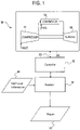
FIG. 1 shows a dataflow diagram of asystem 50 according to one embodiment. Thesystem 50 may include one ormore turbines 60. For simplicity, only oneturbine 60 is illustrated inFIG. 1 . Theturbine 60 can be any type of type of turbine. Indeed, theturbine 60 could be a gas turbine, a steam turbine or other device that converts a fuel into electricity. - In the event the
turbine 60 is a gas turbine, theturbine 60 may include a compressor 52 to draw in and compress air; a combustor 54 (or burner) to add fuel to heat the compressed air; and aturbine section 56 to extract power from the hot air flow. - The
system 50 may also include acontroller 62 coupled to theturbine 60. Thecontroller 62 receives information from theturbine 60 and, based on that information, may vary the operation of theturbine 60. Accordingly, the communication between thecontroller 62 and theturbine 60 may be bidirectional as indicated bycommunication pathway 63. - In one embodiment, the
controller 62 is coupled to anassessor 64. In such an embodiment, theassessor 64 receives information from thecontroller 62 and optionally,additional information 66 from additional information sources (not shown) to produce one ormore reports 70. - The
additional information 66 may include, but is not limited to, on-site monitoring information. In one embodiment, the on-site monitoring information is related to the compressor 52. This on-site monitoring information may include, but is not limited to, hours of operation, inlet conditioning, fogger information, part load operation, water wash information, inlet air quality and other sensor information. Of course, other types of information could be included in theadditional information 66. - The
assessor 64 may be implemented in hardware, software, or some combination thereof (firmware). Thereport 70 can include one or more different types of information. According to the herein claimed invention, thereport 70 includes a root cause report. - Referring to
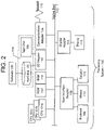
FIG. 2 , there is shown an embodiment of aprocessing system 100 for implementing the teachings herein. Theprocessing system 100 may include the assessor 64 (Fig. 1 ). In this embodiment, thesystem 100 has one or more central processing units (processors) 101a, 101b, 101c, etc. (collectively or generically referred to as processor(s) 101). In one embodiment, each processor 101 may include a reduced instruction set computer (RISC) microprocessor. Processors 101 are coupled tosystem memory 114 and various other components via asystem bus 113. Read only memory (ROM) 102 is coupled to thesystem bus 113 and may include a basic input/output system (BIOS), which controls certain basic functions of thesystem 100. -
FIG. 2 further depicts an input/output (I/O)adapter 107 and anetwork adapter 106 coupled to thesystem bus 113. I/O adapter 107 may be a small computer system interface (SCSI) adapter that communicates with ahard disk 103 and/ortape storage drive 105 or any other similar component. I/O adapter 107,hard disk 103, andtape storage device 105 are collectively referred to herein asmass storage 104. Anetwork adapter 106interconnects bus 113 with anoutside network 116 enablingdata processing system 100 to communicate with other such systems. A screen (e.g., a display monitor) 115 can be connected tosystem bus 113 bydisplay adaptor 112, which may include a graphics adapter to improve the performance of graphics intensive applications and a video controller. In one embodiment,adapters system bus 113 via an intermediate bus bridge (not shown). Suitable I/O buses for connecting peripheral devices such as hard disk controllers, network adapters, and graphics adapters typically include common protocols, such as the Peripheral Components Interface (PCI). Additional input/output devices are shown as connected tosystem bus 113 via user interface adapter 108 anddisplay adapter 112. Akeyboard 109,mouse 110, andspeaker 111 are all interconnected tobus 113 via user interface adapter 108, which may include, for example, an I/O chip integrating multiple device adapters into a single integrated circuit. - It will be appreciated that the
system 100 can be any suitable computer or computing platform, and may include a terminal, wireless device, information appliance, device, workstation, mini-computer, mainframe computer, personal digital assistant (PDA) or other computing device. It shall be understood that thesystem 100 may include multiple computing devices linked together by a communication network. For example, there may exist a client-server relationship between two systems and processing may be split between the two. - Any computer operating system may be utilized by the
system 100. As illustrated, thesystem 100 also includes anetwork interface 106 for communicating over anetwork 116. Thenetwork 116 can be a local-area network (LAN), a metro-area network (MAN), or wide-area network (WAN), such as the Internet or World Wide Web. - Users of the
system 100 can connect to thenetwork 116 through any suitable network interface, such as standard telephone lines, digital subscriber line, LAN or WAN links (e.g., T1, T3), broadband connections (Frame Relay, ATM), and wireless connections (e.g., 802.11(a), 802.11(b), 802.11(g)). - As disclosed herein, the
system 100 may include machine-readable instructions stored on machine-readable media (for example, the hard disk 104) to execute one or more methods disclosed herein. As discussed herein, the instructions may be referred to as "software" 120. Thesoftware 120 may be produced using software development tools as are known in the art. Thesoftware 120 may include various tools and features for providing user interaction capabilities as are known in the art. -
FIG. 3 is a dataflow diagram of asystem 300 according to one embodiment. In this embodiment, theturbine 60 producesturbine data 302. Of course, theturbine data 302 could be compiled at a controller (not shown) or other computing device that receives information from a turbine or other machine. It shall be understood that while the description ofFIG. 3 relates to a turbine, thesystem 300 could replace the turbine with any type of machine from which data may be collected. - The
turbine data 302 can include one or more of: the heat rate (HR), the measured power output (DWATT), turbine speed (high pressure shaft) (TNH), gross corrected power, atmospheric pressure (AFPAP), measured turbine exhaust pressure loss (AFPEP), compressor efficiency and compressor flow rate. In addition, theturbine data 302 can include times when, for example, a water wash was performed on the compressor. - The
turbine data 302 is provided to anassessor 301. Theassessor 301 could be the same as or a portion of theassessor 64 shown inFIG. 1 . In one embodiment, theassessor 301 includes a signal-processing module 304. The signal-processing module 304 filters and sorts theturbine data 302 in one embodiment. In one embodiment, the signal-processing module 304 could be omitted. - In the event that that signal-
processing module 304 is present, it can perform one or more of the following: operating mode filtering; signal smoothing (using either median or Savitzky-Golay (SG)) filtering; and data normalization. Of course, the signal-processing module 304 could perform other types of processing on theturbine data 302. Regardless of the type of filtering of processing, the signal-processing module 304 produces processeddata 306. - The processed
data 306 is provided to achange detection module 308 in one embodiment. As described above, the signal-processing module 304 can be omitted. In such a case, theturbine data 302 can be provided directly to thechange detection module 308. - The
change detection module 308 is generally configured to test data over time and detect time-based variations in theturbine data 302. In particular, thechange detection module 306 applies tests to the data and determines if any of the values or changes in the values exceeds an associated threshold. - There are several types of detection schemes (tests) that can be implemented by the
change detection module 306. These schemes include, but are not limited to, a Hotelling T2 transform test, a Likelihood Ratio test, a combination of the Hotelling T2 transform test and the Likelihood Ratio test, a z score calculation, a two sample t test, an entropy base test, an offline water detection test, a mean or base value shift test and a high slope detection test. In one embodiment, one or more of these tests are performed on one or both of the HR and DWATT values received from theturbine 60. Of course, other types of tests could be performed and those listed can be implemented by one of skill in the art. In one embodiment, the detection of an undesirable change in any of the parameters in theturbine data 302 can result in the generation of an alarm. - The
change detection module 308 produces detectedchanges data 310. This detected changesdata 310 represents the particular alarms (or lack thereof) generated based on the tests performed in thechange detection module 308. In one embodiment, the detectedchanges data 310 can include a table of the states of all of the monitored turbine parameters as they existed when an alarm was generated. The detected changesdata 310 are be combined to form an evidence matrix as described below, according to the herein claimed invention. -
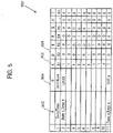
FIG. 4 shows anexample portion 400 of an evidence matrix according to one embodiment. Theportion 400 illustrates an entry in an evidence matrix where both an HR alarm (column 402) and a DWATT alarm (column 404) were created for a particular unit (e.g., for a particular turbine). Of course, other types of alarms could be included in theportion 400. Theportion 400 also includes indications of the state of other additional parameters 406-420. The states of the additional parameters 406-420 indicate whether those parameters where within normal operating conditions or had been performed recently (in the case of, for example, water washes) when the HR or DWATT alarm was created. -
Multiple portions 400 can be created over time for an individual unit and across a fleet of units. Theportions 400 can all be combined to form anevidence matrix 500 as shown inFIG. 5 . Theevidence matrix 500 identifies the unit (column 502) and the time of the alarm (column 504) in one embodiment. It shall be understood that theportion 400 and theevidence matrix 500 can include only entries for when the turbine or a portion thereof (e.g., the compressor) failed in one embodiment. Of course, the definition of failure is variable and depends on the context. According to one embodiment, each entry in theevidence matrix 500 can also include an indication of the actual failure cause. - Referring again to
FIG. 3 , theevidence matrix 500 can be formed fromindividual portions 400 contained in the detectedchanges data 310 and stored in adatabase 314. Theevidence matrix 500 is utilized as part of a root cause analysis (RCA) according to the herein claimed invention. According to the herein claimed invention, the RCA includes utilizing a BBN model. The BBN model is created from the evidence matrix according to the herein claimed invention. - The detected changes
data 310 is provided to aroot cause analyzer 312. In one embodiment, theroot cause analyzer 312 analyzes the detectedchanges 310 for a current alarm condition and creates a prediction of the root cause of the alarm. For example, assume that an HR alarm was encountered at the same time that the compressor was receiving a water wash. In such a case, the HR alarm could be predicted to be causes by the fact that the water wash was occurring. It shall be understood that the above example is simplistic and is presented by way of example, not as a limitation. -
FIG. 6 illustrates aconstruct 600 utilized in theroot cause analyzer 314 in one embodiment. The construct can be formed based on, for example, examination of an evidence matrix 500 (FIG. 5 ). In one embodiment, a more complete construct that provides a probabilistic framework for all possible measured values can be created from system knowledge and the evidence matrix and then trimmed to remove non-contributing or non-detectable information according to known principles. Theconstruct 600 illustrated inFIG. 6 is such a trimmed version. - As discussed above, each entry in the evidence matrix can include an indication of the actual cause of the alarm state. Such actual causes are also referred to herein as "root causes" and are shown in
FIG. 6 as byroot cause bubble 602. It shall be understood that the causes can be selected from, in one embodiment, compressor issues, turbine malfunction, inlet condition changes, firing temperature changes, water wash, sensor calibration issues, bleed valve open and filter change outs to name but a few. - A
separate construct 600 can be developed for each root cause. Theconstruct 600 can include other, different parameters 604-620. The particular arrangement and connections between the parameters is based on the actual observed data in one embodiment. - The
construct 600 forms the basis for a BBN and is based on the belief of a human expert. In more detail, a BBN is graphical representation of the variable of a domain of interest and represents the relationships among variable in aconstruct 600 as illustrated inFIG. 6 . In one embodiment, theconstruct 600 is a direct acyclic graph (DAG). In a BBN, the variables (604-620) have a finite set of states and are connected by edges (e.g., edges 622) to form a DAG. Each variable A has parents, B1 ..., Bn. For example, inFIG. 6 , bubbles 614, 618 and 620 are parents ofbubble 616. The probability that B happened given that A happened is defined by Baye's Rule which is illustrated in Eg. 1.
- Referring again to
FIG. 3 , theroot cause analyzer 312 can compare current detectedchanges data 310 to the BBN shown inFIG. 6 for one or more of the root causes. Such a comparison will yield a prediction of the root cause based on the state (alarm or not) of all of the measurable parameters. In such an embodiment, thereport 70 includes an indication of the root cause that most closely matches the current conditions. Of course, thereport 70 could include a listing of all of the root causes defined in the system and the probability that each of them is the root cause of the current alarms. - In one embodiment, based on the root cause a repair or corrective action is actually taken. The actual cause of the alarm may turn out to be different than that predicted by the
root cause analyzer 312. In one embodiment, the system illustrated inFIG. 3 includes alearning tool 316 that causes one or more of the BBN's to be changed based on this new information. In addition, the BBN's can be updated over time as more data is collected. - According to another embodiment, the systems and methods disclosed herein can be utilized to provide maintenance recommendations. To that end, the system can also include
maintenance analyzer 318. Themaintenance analyzer 318 is configured to analyze thereport 70 and produce amaintenance recommendation 320. Suppose for example that thereport 70 indicates that a particular turbine has an 80% chance of low compressor efficiency (i.e. that there is 80% chance that the compressor is the cause of the current alarm). Based on rules, themaintenance analyzer 318 may create amaintenance recommendation 320 stating that the compressor related components are to be checked during the next maintenance interval. Of course, the particular rules utilized by themaintenance analyzer 318 can be determined and varied based on the context. -
FIG. 7 is a dataflow diagram illustrating a system 700 according to another embodiment of the present invention. It shall be understood that the system 700 illustrated inFIG. 7 could be integrated into thesystem 300 shown inFIG. 3 . In this embodiment, theturbine 60 producesturbine data 702. Of course, theturbine data 702 could be compiled at a controller (not shown) or other computing device that receives information from a turbine or other machine. It shall be understood that while the description ofFIG. 7 relates to a turbine, the system 700 could replace the turbine with any type of machine from which data may be collected. Furthermore, it shall be understood that the system 700 can includemultiple turbines 60 that form a fleet. - In general, from the
turbine data 702 the system 700 produces a scorecard. The scorecard can be either a fleetwide scorecard 704 or aunit scorecard 706 for a particular unit. In one embodiment, the fleetwide scorecard 704 includesseveral unit scorecards 706 combined together. - In more detail, the
turbine data 702 is provided to anassessor 701 that creates one or both of thescorecards turbine data 702 can include one or more of: the heat rate (HR), the measured power output (DWATT), turbine speed (high pressure shaft) (TNH), gross corrected power, atmospheric pressure (AFPAP), measured turbine exhaust pressure loss (AFPEP), compressor efficiency (COMP_EFF) and compressor flow rate (COMP_FLOW). In addition, theturbine data 702 can include times when, for example, a water wash was performed on the compressor. - The
turbine data 702 is provided to anassessor 701. Theassessor 701 could be the same as or a portion of theassessor 64 shown inFIG. 1 . In one embodiment, theassessor 701 includes a signal-processing module 708. The signal-processing module 708 filters and sorts theturbine data 702 in one embodiment. In one embodiment, the signal-processing module 708 could be omitted. The signal-processing module 708 could perform some or all of the same functions as the signal-processing module 304 shown inFIG. 3 . - According to one embodiment, the
signal processing module 708 produces processeddata 710. The processeddata 710 includes, in one embodiment, a series of pairs of heat rate data where each pair indicates the heat rate following successive water washes. Of course, other data pairs related to a water wash could be included. In addition, any of theother turbine data 702 could be included in the processed data 710 (whether processed or not). - The
assessor 701 also includes achange detection module 712 that determines if the change in the pairs or other information exceeds a threshold and outputs detectedchanges data 714. - The
assessor 701 of this embodiment may also include ascorecard generator 712 configured to generate one or both of the fleetwide scorecard 704 and theunit scorecard 706 from the detected changes. In one embodiment, theunit scorecard 706 includes an indication of whether the performance of the unit is degrading and, if so, by how much. One metric that can be utilized for such a determination is a mean shift change. -
FIG. 8 shows a graph of performance degradation over time. In afirst time period 801, the heat rate (trace 802) is at first level, L1 following a first water wash (illustrated by line 803). In a second time period 804 theheat rate 802 is a second level following asecond water wash 805. The difference between the first level, L1, and the second level, L2, indicates an amount of performance degradation that can be tracked overtime. Thechange detection module 712 can determine the difference between L1 and L2 (FIG. 7 ) in one embodiment. In one embodiment, theunit scorecard 706 can include different values based on the level of performance degradation. - For example, and referring again to
FIG. 7 , theunit scorecard 706 could indicate that the performance is not degrading, is degrading by less than one percent per wash or is degrading by more than one percent per wash. Of course, such information could also be used to predict future degradation of the unit over time. - In the case of the fleet
wide scorecard 704, for the performance degradation of the fleet as a whole could be modeled based onunit scorecards 706 for each performance metric. - In one embodiment, performance degradation predictions can be included in the fleet
wide scorecard 704, the unit scorecard, or both. In one embodiment, such predictions are based on a model created by a Kalman Filtering process. In such a process the heat rate is modeled, initially, by equation 2:
- In view of the above, in one embodiment, the system shown in
FIG. 7 can utilize current parameters and an operating profile of the turbine to predict a rate of change in its heat rate values now or at a future time. Such future predictions can also be utilized by the maintenance analyzer 318 (FIG. 3 ) to determine when specific maintenance may be performed. - While the invention has been described in detail in connection with only a limited number of embodiments, it should be readily understood that the invention is not limited to such disclosed embodiments. Rather, the invention can be modified to incorporate any number of variations, alterations, substitutions or equivalent arrangements not heretofore described, but which are commensurate with the spirit and scope of the invention. Additionally, while various embodiments of the invention have been described, it is to be understood that aspects of the invention may include only some of the described embodiments. Accordingly, the invention is not to be seen as limited by the foregoing description, but is only limited by the scope of the appended claims.
Claims (13)
- A turbine performance diagnostic system (50) that creates a performance report for one or more turbines, the system (50) comprising:an assessment module that receives operating data from at least one turbine (60) and produces a performance report (70) from the operating data, the assessment module including:a change detection module (308) configured to determine when at least one parameter has changed beyond an associated threshold and generate an alarm; anda root cause analyzer (312) coupled to the change detection module (308) that predicts a root cause of the alarm utilizing a Bayesian Belief Network (BBN), wherein the BBN is created from an evidence matrix (500) including a plurality of entries corresponding to previously-detected alarm states and indications of a state of additional parameters, wherein the indications of the state of the additional parameters indicate whether those parameters were within normal operation conditions or had been performed recently,wherein the performance report (70) includes an indication of the predicted root cause.
- The system (50) of claim 1, wherein the change detection module (308) performs at least one of: a Hotelling T2 transform test, a Likelihood Ratio test, a combination of the Hotelling T2 transform test and a Likelihood Ratio test, a z score calculation, a two sample t test, an entropy base test, an offline water detection test, a mean or base value shift test and a high slope detection test to generate the alarm.
- The system (50) of claim 1, wherein the BBN is formed based on prior operating data related to the at least one turbine (60).
- The system (50) of any of the preceding claims 1, wherein the evidence matrix (500) includes a plurality of portions, each portion including an indication of other alarm conditions present when a first alarm was generated.
- The system of the preceding claim, wherein the evidence matrix is at least partially formed from operating data from turbines other than the at least one turbine.
- The system of claim 4, wherein the evidence matrix further includes an indication of the actual cause of the alarm for each portion.
- The system of any preceding claim, further including:a database for storing the BBN; anda learning tool coupled to the database that modifies the BBN based on the accuracy of BBN root cause predictions.
- The system (50) of any preceding claim, further comprising:
a maintenance analyzer (318) that creates a maintenance recommendation (320) based on the report. - The system of any preceding claim, wherein the parameter is a heat rate of one of the turbines.
- The system of the preceding claim, wherein the parameter is the degradation in heat rate after a compressor water wash.
- A method of determining a root cause of a turbine alarm for at least one turbine, the method comprising:determining at a computing device that the turbine alarm exists;determining at the computing device which, if any, other alarm conditions exist when the alarm conditions exist to create an event portion; andpredicting the root cause of the event from the event portion by comparing the event portion to a Bayesian Belief Network (BBN), wherein the BBN is created from an evidence matrix (500) including a plurality of entries corresponding to previously-detected alarm states and indications of a state of additional parameters,wherein the indications of the state of the additional parameters indicate whether those parameters were within normal operation conditions or had been performed recently.
- The method of claim 11, wherein the BBN is formed based on prior operating data related to the at least one turbine (60).
- The method of any of claims 11 or 12, wherein the evidence matrix (500) is at least partially formed from operating data from turbines other than the at least one turbine (60).
Applications Claiming Priority (1)
| Application Number | Priority Date | Filing Date | Title |
|---|---|---|---|
| US12/956,689 US8751423B2 (en) | 2010-11-30 | 2010-11-30 | Turbine performance diagnostic system and methods |
Publications (4)
| Publication Number | Publication Date |
|---|---|
| EP2458178A2 EP2458178A2 (en) | 2012-05-30 |
| EP2458178A3 EP2458178A3 (en) | 2015-12-16 |
| EP2458178B1 EP2458178B1 (en) | 2018-04-18 |
| EP2458178B2 true EP2458178B2 (en) | 2022-07-20 |
Family
ID=45002782
Family Applications (1)
| Application Number | Title | Priority Date | Filing Date |
|---|---|---|---|
| EP11190153.4A Active EP2458178B2 (en) | 2010-11-30 | 2011-11-22 | Turbine performance diagnositic system and methods |
Country Status (3)
| Country | Link |
|---|---|
| US (1) | US8751423B2 (en) |
| EP (1) | EP2458178B2 (en) |
| JP (1) | JP6088131B2 (en) |
Families Citing this family (11)
| Publication number | Priority date | Publication date | Assignee | Title |
|---|---|---|---|---|
| US20120283885A1 (en) * | 2011-05-04 | 2012-11-08 | General Electric Company | Automated system and method for implementing statistical comparison of power plant operations |
| EP2738373A1 (en) * | 2012-12-03 | 2014-06-04 | Siemens Aktiengesellschaft | Gas turbine fuel supply method and arrangement |
| JP5751496B2 (en) * | 2012-12-27 | 2015-07-22 | 横河電機株式会社 | Event analysis apparatus and computer program |
| US20140278241A1 (en) * | 2013-03-15 | 2014-09-18 | General Electric Company | Performance monitoring and analysis for power plants |
| US9494492B2 (en) * | 2013-03-15 | 2016-11-15 | United Technologies Corporation | Use of SS data trends in fault resolution process |
| US20140324363A1 (en) * | 2013-04-30 | 2014-10-30 | United Technologies Corporation | System reliability analysis and management using physics-based models embedded in a baysian network |
| US20150000247A1 (en) * | 2013-07-01 | 2015-01-01 | General Electric Company | System and method for detecting airfoil clash within a compressor |
| IN2013CH03925A (en) * | 2013-09-02 | 2015-09-11 | Appnomic Systems Private Ltd | |
| US10330018B2 (en) | 2014-03-24 | 2019-06-25 | Rolls-Royce Corporation | Integrating design and field management of gas turbine engine components with a probabilistic model |
| KR101863781B1 (en) * | 2016-09-08 | 2018-06-01 | 두산중공업 주식회사 | Apparatus and method for detecting abnormal vibration |
| US11238129B2 (en) * | 2019-12-11 | 2022-02-01 | International Business Machines Corporation | Root cause analysis using Granger causality |
Citations (3)
| Publication number | Priority date | Publication date | Assignee | Title |
|---|---|---|---|---|
| US20050133211A1 (en) † | 2003-12-19 | 2005-06-23 | Osborn Mark D. | Heat exchanger performance monitoring and analysis method and system |
| US20060074591A1 (en) † | 2004-09-30 | 2006-04-06 | Jammu Vinay B | Systems and methods for monitoring fouling and slagging in heat transfer devices in coal fired power plants |
| US20100138267A1 (en) † | 2009-08-31 | 2010-06-03 | Sameer Vittal | System and method for wind turbine health management |
Family Cites Families (45)
| Publication number | Priority date | Publication date | Assignee | Title |
|---|---|---|---|---|
| EP0050610B1 (en) | 1980-04-22 | 1986-12-30 | The Boeing Company | Real-time performance monitoring of gas turbine engines |
| US4548040A (en) | 1984-05-11 | 1985-10-22 | Elliott Turbomachinery Company, Inc. | Method and apparatus for determining when to initiate cleaning of turbocharger turbine blades |
| JPS6433697A (en) * | 1987-07-30 | 1989-02-03 | Anritsu Corp | Abnormality diagnosis method for system |
| JPH0721029A (en) * | 1993-07-05 | 1995-01-24 | Komatsu Ltd | Inference device |
| US5517852A (en) | 1994-11-02 | 1996-05-21 | Standard Aero Limited | Diagnostic performance testing for gas turbine engines |
| JPH09112294A (en) | 1995-10-20 | 1997-04-28 | Toshiba Corp | Performance monitoring device for gas turbine intake cooling system |
| GB2321720A (en) | 1997-02-04 | 1998-08-05 | Secr Defence | Modelling a system with more parameters than sensors |
| US6591182B1 (en) | 2000-02-29 | 2003-07-08 | General Electric Company | Decision making process and manual for diagnostic trend analysis |
| GB0029760D0 (en) | 2000-12-06 | 2001-01-17 | Secr Defence Brit | Tracking systems for detecting sensor errors |
| US6498978B2 (en) | 2001-05-18 | 2002-12-24 | General Electric Company | System and method for monitoring thermal state to normalize engine trending data |
| US6687596B2 (en) | 2001-08-31 | 2004-02-03 | General Electric Company | Diagnostic method and system for turbine engines |
| US6804612B2 (en) | 2001-10-30 | 2004-10-12 | General Electric Company | Methods and systems for performing integrated analyzes, such as integrated analyzes for gas turbine power plants |
| US20030125906A1 (en) | 2001-12-28 | 2003-07-03 | Guaglardi Paul A. | Method and apparatus for assessing the impact of individual parts of a gas turbine component on the overall thermal performance of a gas turbine |
| JP4495971B2 (en) | 2002-01-25 | 2010-07-07 | アルストム テクノロジー リミテッド | Method for operating a gas turbine group |
| US20070234730A1 (en) | 2002-06-28 | 2007-10-11 | Markham James R | Method and apparatus for monitoring combustion instability and other performance deviations in turbine engines and like combustion systems |
| JP2004108291A (en) | 2002-09-19 | 2004-04-08 | Ishikawajima Harima Heavy Ind Co Ltd | Part deterioration prediction method and performance deterioration prediction method for gas turbine engine |
| US6909960B2 (en) | 2002-10-31 | 2005-06-21 | United Technologies Corporation | Method for performing gas turbine performance diagnostics |
| US6823675B2 (en) | 2002-11-13 | 2004-11-30 | General Electric Company | Adaptive model-based control systems and methods for controlling a gas turbine |
| US6962043B2 (en) | 2003-01-30 | 2005-11-08 | General Electric Company | Method and apparatus for monitoring the performance of a gas turbine system |
| JP2005133583A (en) | 2003-10-29 | 2005-05-26 | Hitachi Ltd | Gas turbine cleaning time determining device and method |
| JP2005248848A (en) | 2004-03-04 | 2005-09-15 | Hitachi Ltd | Diagnostic method and device for gas turbine |
| US7487029B2 (en) | 2004-05-21 | 2009-02-03 | Pratt & Whitney Canada | Method of monitoring gas turbine engine operation |
| JP2006057595A (en) | 2004-08-23 | 2006-03-02 | Hitachi Ltd | Gas turbine performance diagnosing system and its method |
| US20060212281A1 (en) | 2005-03-21 | 2006-09-21 | Mathews Harry Kirk Jr | System and method for system-specific analysis of turbomachinery |
| JP2007002673A (en) | 2005-06-21 | 2007-01-11 | Ishikawajima Harima Heavy Ind Co Ltd | Gas turbine performance analyzing and estimating method |
| US7286923B2 (en) | 2005-09-30 | 2007-10-23 | General Electric Company | System and method for estimating turbine engine deterioration rate with noisy data |
| JP4468282B2 (en) | 2005-10-13 | 2010-05-26 | 株式会社日立製作所 | Gas turbine performance diagnostic method and diagnostic system |
| JP4801452B2 (en) | 2006-01-19 | 2011-10-26 | 三菱重工業株式会社 | Abnormality monitoring method and apparatus for gas turbine |
| JP4513771B2 (en) | 2006-02-28 | 2010-07-28 | 株式会社日立製作所 | Performance monitoring method and system for single-shaft combined cycle plant |
| US7801660B2 (en) | 2006-07-31 | 2010-09-21 | General Electric Company | Methods and systems for estimating compressor fouling impact to combined cycle power plants |
| JP4824518B2 (en) | 2006-10-05 | 2011-11-30 | 株式会社日立製作所 | Gas turbine performance diagnostic system, diagnostic method and display screen |
| US8685176B2 (en) * | 2006-10-16 | 2014-04-01 | Ecoservices, Llc | System and method for optimized gas turbine compressor cleaning and performance measurement |
| US8010320B2 (en) | 2006-11-17 | 2011-08-30 | United Technologies Corporation | Reducing gas turbine performance tracking estimation non-repeatability |
| US20080126012A1 (en) | 2006-11-29 | 2008-05-29 | United Technologies Corpoation | State initialization for gas turbine engine performance diagnostics |
| US7702447B2 (en) | 2006-12-18 | 2010-04-20 | United Technologies Corporation | Method and system for identifying gas turbine engine faults |
| US20080154473A1 (en) | 2006-12-22 | 2008-06-26 | United Technologies Corporation | Gas turbine engine performance data validation |
| US7441448B2 (en) | 2007-01-24 | 2008-10-28 | United Technologies Corporation | Process for adapting measurement suite configuration for gas turbine performance diagnostics |
| US7788014B2 (en) | 2007-03-05 | 2010-08-31 | United Technologies Corporation | Process and methodology for root cause identification in gas turbine engine performance tracking |
| RU2327061C1 (en) | 2007-04-11 | 2008-06-20 | Общество с ограниченной ответственностью Научно-исследовательское предприятие "Энерготехнология" | Method of increasing compressor efficiency |
| US8437904B2 (en) | 2007-06-12 | 2013-05-07 | The Boeing Company | Systems and methods for health monitoring of complex systems |
| US8250017B2 (en) * | 2007-08-23 | 2012-08-21 | General Electric Company | System and method for prediction of gas turbine trips due to gas control valve failures |
| DE102008022459A1 (en) | 2008-05-08 | 2009-11-12 | Mtu Aero Engines Gmbh | Apparatus and method for monitoring a gas turbine |
| JP5386877B2 (en) * | 2008-08-04 | 2014-01-15 | 株式会社デンソー | Map display device |
| JP5101465B2 (en) * | 2008-11-25 | 2012-12-19 | 三菱重工業株式会社 | Equipment defect management method |
| US8133446B2 (en) * | 2009-12-11 | 2012-03-13 | Uop Llc | Apparatus for producing hydrocarbon fuel |
-
2010
- 2010-11-30 US US12/956,689 patent/US8751423B2/en active Active
-
2011
- 2011-11-22 EP EP11190153.4A patent/EP2458178B2/en active Active
- 2011-11-25 JP JP2011256888A patent/JP6088131B2/en active Active
Patent Citations (3)
| Publication number | Priority date | Publication date | Assignee | Title |
|---|---|---|---|---|
| US20050133211A1 (en) † | 2003-12-19 | 2005-06-23 | Osborn Mark D. | Heat exchanger performance monitoring and analysis method and system |
| US20060074591A1 (en) † | 2004-09-30 | 2006-04-06 | Jammu Vinay B | Systems and methods for monitoring fouling and slagging in heat transfer devices in coal fired power plants |
| US20100138267A1 (en) † | 2009-08-31 | 2010-06-03 | Sameer Vittal | System and method for wind turbine health management |
Also Published As
| Publication number | Publication date |
|---|---|
| JP6088131B2 (en) | 2017-03-01 |
| JP2012118981A (en) | 2012-06-21 |
| US8751423B2 (en) | 2014-06-10 |
| EP2458178A2 (en) | 2012-05-30 |
| CN102539129A (en) | 2012-07-04 |
| US20120136819A1 (en) | 2012-05-31 |
| EP2458178B1 (en) | 2018-04-18 |
| EP2458178A3 (en) | 2015-12-16 |
Similar Documents
| Publication | Publication Date | Title |
|---|---|---|
| EP2458178B2 (en) | Turbine performance diagnositic system and methods | |
| EP3055747B1 (en) | Correlation and annotation of time series data sequences to extracted or existing discrete data | |
| US7369932B2 (en) | System and method for turbine engine fault detection using discrete event system modeling | |
| KR101955305B1 (en) | Gas turbine sensor failure detection utilizing a sparse coding methodology | |
| JP5875726B1 (en) | Preprocessor for abnormality sign diagnosis apparatus and processing method thereof | |
| US20080201104A1 (en) | Monitoring a degrading system | |
| EP3055746B1 (en) | Correlation and annotation of time series data sequences to extracted or existing discrete data | |
| CN104272207A (en) | Method and system for real time gas turbine performance advisory | |
| CN104756029B (en) | A kind of system of the parts group of monitoring device | |
| US8712729B2 (en) | Anomalous data detection method | |
| CN102054218A (en) | Turbine operation degradation determination system and method | |
| JP2011090382A (en) | Monitoring system | |
| EP2317082A2 (en) | Turbine life assessment and inspection system and methods | |
| JPH08202444A (en) | Method and device for diagnosing abnormality of machine facility | |
| JP6523815B2 (en) | Plant diagnostic device and plant diagnostic method | |
| CN113656906A (en) | Non-stationary multivariable causal relationship analysis method for gas turbine | |
| JP6714498B2 (en) | Equipment diagnosis device and equipment diagnosis method | |
| Yan et al. | Two-stage degradation assessment and prediction method for aircraft engine based on data fusion | |
| JP2002108440A (en) | Damage diagnosing device for power generation facilities | |
| US11339763B2 (en) | Method for windmill farm monitoring | |
| US20060085102A1 (en) | Methods for establishing alerts and/or alert limits for monitoring mechanical devices | |
| WO2021140942A1 (en) | Diagnosing device, diagnosing method, and program | |
| Eustace | A real-world application of fuzzy logic and influence coefficients for gas turbine performance diagnostics | |
| CN112906237A (en) | Engine component fault analysis method and system | |
| CN102539129B (en) | turbine performance diagnostic system and method |
Legal Events
| Date | Code | Title | Description |
|---|---|---|---|
| PUAI | Public reference made under article 153(3) epc to a published international application that has entered the european phase |
Free format text: ORIGINAL CODE: 0009012 |
|
| AK | Designated contracting states |
Kind code of ref document: A2 Designated state(s): AL AT BE BG CH CY CZ DE DK EE ES FI FR GB GR HR HU IE IS IT LI LT LU LV MC MK MT NL NO PL PT RO RS SE SI SK SM TR |
|
| AX | Request for extension of the european patent |
Extension state: BA ME |
|
| PUAL | Search report despatched |
Free format text: ORIGINAL CODE: 0009013 |
|
| AK | Designated contracting states |
Kind code of ref document: A3 Designated state(s): AL AT BE BG CH CY CZ DE DK EE ES FI FR GB GR HR HU IE IS IT LI LT LU LV MC MK MT NL NO PL PT RO RS SE SI SK SM TR |
|
| AX | Request for extension of the european patent |
Extension state: BA ME |
|
| RIC1 | Information provided on ipc code assigned before grant |
Ipc: F02C 9/00 20060101AFI20151106BHEP Ipc: G06N 7/00 20060101ALI20151106BHEP |
|
| 17P | Request for examination filed |
Effective date: 20160616 |
|
| RBV | Designated contracting states (corrected) |
Designated state(s): AL AT BE BG CH CY CZ DE DK EE ES FI FR GB GR HR HU IE IS IT LI LT LU LV MC MK MT NL NO PL PT RO RS SE SI SK SM TR |
|
| STAA | Information on the status of an ep patent application or granted ep patent |
Free format text: STATUS: EXAMINATION IS IN PROGRESS |
|
| 17Q | First examination report despatched |
Effective date: 20170607 |
|
| GRAP | Despatch of communication of intention to grant a patent |
Free format text: ORIGINAL CODE: EPIDOSNIGR1 |
|
| STAA | Information on the status of an ep patent application or granted ep patent |
Free format text: STATUS: GRANT OF PATENT IS INTENDED |
|
| INTG | Intention to grant announced |
Effective date: 20171205 |
|
| GRAS | Grant fee paid |
Free format text: ORIGINAL CODE: EPIDOSNIGR3 |
|
| GRAA | (expected) grant |
Free format text: ORIGINAL CODE: 0009210 |
|
| STAA | Information on the status of an ep patent application or granted ep patent |
Free format text: STATUS: THE PATENT HAS BEEN GRANTED |
|
| AK | Designated contracting states |
Kind code of ref document: B1 Designated state(s): AL AT BE BG CH CY CZ DE DK EE ES FI FR GB GR HR HU IE IS IT LI LT LU LV MC MK MT NL NO PL PT RO RS SE SI SK SM TR |
|
| REG | Reference to a national code |
Ref country code: GB Ref legal event code: FG4D |
|
| REG | Reference to a national code |
Ref country code: CH Ref legal event code: EP |
|
| REG | Reference to a national code |
Ref country code: AT Ref legal event code: REF Ref document number: 990740 Country of ref document: AT Kind code of ref document: T Effective date: 20180515 |
|
| REG | Reference to a national code |
Ref country code: IE Ref legal event code: FG4D |
|
| REG | Reference to a national code |
Ref country code: DE Ref legal event code: R096 Ref document number: 602011047544 Country of ref document: DE |
|
| REG | Reference to a national code |
Ref country code: NL Ref legal event code: MP Effective date: 20180418 |
|
| REG | Reference to a national code |
Ref country code: DE Ref legal event code: R026 Ref document number: 602011047544 Country of ref document: DE |
|
| PLBI | Opposition filed |
Free format text: ORIGINAL CODE: 0009260 |
|
| REG | Reference to a national code |
Ref country code: LT Ref legal event code: MG4D |
|
| PG25 | Lapsed in a contracting state [announced via postgrant information from national office to epo] |
Ref country code: NL Free format text: LAPSE BECAUSE OF FAILURE TO SUBMIT A TRANSLATION OF THE DESCRIPTION OR TO PAY THE FEE WITHIN THE PRESCRIBED TIME-LIMIT Effective date: 20180418 |
|
| 26 | Opposition filed |
Opponent name: SIEMENS AKTIENGESELLSCHAFT Effective date: 20180830 |
|
| PG25 | Lapsed in a contracting state [announced via postgrant information from national office to epo] |
Ref country code: FI Free format text: LAPSE BECAUSE OF FAILURE TO SUBMIT A TRANSLATION OF THE DESCRIPTION OR TO PAY THE FEE WITHIN THE PRESCRIBED TIME-LIMIT Effective date: 20180418 Ref country code: BG Free format text: LAPSE BECAUSE OF FAILURE TO SUBMIT A TRANSLATION OF THE DESCRIPTION OR TO PAY THE FEE WITHIN THE PRESCRIBED TIME-LIMIT Effective date: 20180718 Ref country code: LT Free format text: LAPSE BECAUSE OF FAILURE TO SUBMIT A TRANSLATION OF THE DESCRIPTION OR TO PAY THE FEE WITHIN THE PRESCRIBED TIME-LIMIT Effective date: 20180418 Ref country code: ES Free format text: LAPSE BECAUSE OF FAILURE TO SUBMIT A TRANSLATION OF THE DESCRIPTION OR TO PAY THE FEE WITHIN THE PRESCRIBED TIME-LIMIT Effective date: 20180418 Ref country code: PL Free format text: LAPSE BECAUSE OF FAILURE TO SUBMIT A TRANSLATION OF THE DESCRIPTION OR TO PAY THE FEE WITHIN THE PRESCRIBED TIME-LIMIT Effective date: 20180418 Ref country code: NO Free format text: LAPSE BECAUSE OF FAILURE TO SUBMIT A TRANSLATION OF THE DESCRIPTION OR TO PAY THE FEE WITHIN THE PRESCRIBED TIME-LIMIT Effective date: 20180718 Ref country code: SE Free format text: LAPSE BECAUSE OF FAILURE TO SUBMIT A TRANSLATION OF THE DESCRIPTION OR TO PAY THE FEE WITHIN THE PRESCRIBED TIME-LIMIT Effective date: 20180418 Ref country code: AL Free format text: LAPSE BECAUSE OF FAILURE TO SUBMIT A TRANSLATION OF THE DESCRIPTION OR TO PAY THE FEE WITHIN THE PRESCRIBED TIME-LIMIT Effective date: 20180418 |
|
| PG25 | Lapsed in a contracting state [announced via postgrant information from national office to epo] |
Ref country code: LV Free format text: LAPSE BECAUSE OF FAILURE TO SUBMIT A TRANSLATION OF THE DESCRIPTION OR TO PAY THE FEE WITHIN THE PRESCRIBED TIME-LIMIT Effective date: 20180418 Ref country code: RS Free format text: LAPSE BECAUSE OF FAILURE TO SUBMIT A TRANSLATION OF THE DESCRIPTION OR TO PAY THE FEE WITHIN THE PRESCRIBED TIME-LIMIT Effective date: 20180418 Ref country code: HR Free format text: LAPSE BECAUSE OF FAILURE TO SUBMIT A TRANSLATION OF THE DESCRIPTION OR TO PAY THE FEE WITHIN THE PRESCRIBED TIME-LIMIT Effective date: 20180418 Ref country code: GR Free format text: LAPSE BECAUSE OF FAILURE TO SUBMIT A TRANSLATION OF THE DESCRIPTION OR TO PAY THE FEE WITHIN THE PRESCRIBED TIME-LIMIT Effective date: 20180719 |
|
| REG | Reference to a national code |
Ref country code: AT Ref legal event code: MK05 Ref document number: 990740 Country of ref document: AT Kind code of ref document: T Effective date: 20180418 |
|
| PG25 | Lapsed in a contracting state [announced via postgrant information from national office to epo] |
Ref country code: PT Free format text: LAPSE BECAUSE OF FAILURE TO SUBMIT A TRANSLATION OF THE DESCRIPTION OR TO PAY THE FEE WITHIN THE PRESCRIBED TIME-LIMIT Effective date: 20180820 |
|
| PLAX | Notice of opposition and request to file observation + time limit sent |
Free format text: ORIGINAL CODE: EPIDOSNOBS2 |
|
| PG25 | Lapsed in a contracting state [announced via postgrant information from national office to epo] |
Ref country code: SK Free format text: LAPSE BECAUSE OF FAILURE TO SUBMIT A TRANSLATION OF THE DESCRIPTION OR TO PAY THE FEE WITHIN THE PRESCRIBED TIME-LIMIT Effective date: 20180418 Ref country code: CZ Free format text: LAPSE BECAUSE OF FAILURE TO SUBMIT A TRANSLATION OF THE DESCRIPTION OR TO PAY THE FEE WITHIN THE PRESCRIBED TIME-LIMIT Effective date: 20180418 Ref country code: RO Free format text: LAPSE BECAUSE OF FAILURE TO SUBMIT A TRANSLATION OF THE DESCRIPTION OR TO PAY THE FEE WITHIN THE PRESCRIBED TIME-LIMIT Effective date: 20180418 Ref country code: DK Free format text: LAPSE BECAUSE OF FAILURE TO SUBMIT A TRANSLATION OF THE DESCRIPTION OR TO PAY THE FEE WITHIN THE PRESCRIBED TIME-LIMIT Effective date: 20180418 Ref country code: AT Free format text: LAPSE BECAUSE OF FAILURE TO SUBMIT A TRANSLATION OF THE DESCRIPTION OR TO PAY THE FEE WITHIN THE PRESCRIBED TIME-LIMIT Effective date: 20180418 Ref country code: EE Free format text: LAPSE BECAUSE OF FAILURE TO SUBMIT A TRANSLATION OF THE DESCRIPTION OR TO PAY THE FEE WITHIN THE PRESCRIBED TIME-LIMIT Effective date: 20180418 |
|
| PG25 | Lapsed in a contracting state [announced via postgrant information from national office to epo] |
Ref country code: SM Free format text: LAPSE BECAUSE OF FAILURE TO SUBMIT A TRANSLATION OF THE DESCRIPTION OR TO PAY THE FEE WITHIN THE PRESCRIBED TIME-LIMIT Effective date: 20180418 |
|
| PG25 | Lapsed in a contracting state [announced via postgrant information from national office to epo] |
Ref country code: SI Free format text: LAPSE BECAUSE OF FAILURE TO SUBMIT A TRANSLATION OF THE DESCRIPTION OR TO PAY THE FEE WITHIN THE PRESCRIBED TIME-LIMIT Effective date: 20180418 |
|
| PLBB | Reply of patent proprietor to notice(s) of opposition received |
Free format text: ORIGINAL CODE: EPIDOSNOBS3 |
|
| REG | Reference to a national code |
Ref country code: CH Ref legal event code: PL |
|
| GBPC | Gb: european patent ceased through non-payment of renewal fee |
Effective date: 20181122 |
|
| PG25 | Lapsed in a contracting state [announced via postgrant information from national office to epo] |
Ref country code: MC Free format text: LAPSE BECAUSE OF FAILURE TO SUBMIT A TRANSLATION OF THE DESCRIPTION OR TO PAY THE FEE WITHIN THE PRESCRIBED TIME-LIMIT Effective date: 20180418 Ref country code: LU Free format text: LAPSE BECAUSE OF NON-PAYMENT OF DUE FEES Effective date: 20181122 |
|
| REG | Reference to a national code |
Ref country code: BE Ref legal event code: MM Effective date: 20181130 |
|
| REG | Reference to a national code |
Ref country code: IE Ref legal event code: MM4A |
|
| PG25 | Lapsed in a contracting state [announced via postgrant information from national office to epo] |
Ref country code: CH Free format text: LAPSE BECAUSE OF NON-PAYMENT OF DUE FEES Effective date: 20181130 Ref country code: LI Free format text: LAPSE BECAUSE OF NON-PAYMENT OF DUE FEES Effective date: 20181130 |
|
| PG25 | Lapsed in a contracting state [announced via postgrant information from national office to epo] |
Ref country code: FR Free format text: LAPSE BECAUSE OF NON-PAYMENT OF DUE FEES Effective date: 20181130 Ref country code: IE Free format text: LAPSE BECAUSE OF NON-PAYMENT OF DUE FEES Effective date: 20181122 |
|
| PG25 | Lapsed in a contracting state [announced via postgrant information from national office to epo] |
Ref country code: BE Free format text: LAPSE BECAUSE OF NON-PAYMENT OF DUE FEES Effective date: 20181130 |
|
| PG25 | Lapsed in a contracting state [announced via postgrant information from national office to epo] |
Ref country code: GB Free format text: LAPSE BECAUSE OF NON-PAYMENT OF DUE FEES Effective date: 20181122 |
|
| PG25 | Lapsed in a contracting state [announced via postgrant information from national office to epo] |
Ref country code: MT Free format text: LAPSE BECAUSE OF NON-PAYMENT OF DUE FEES Effective date: 20181122 |
|
| PGFP | Annual fee paid to national office [announced via postgrant information from national office to epo] |
Ref country code: IT Payment date: 20191021 Year of fee payment: 9 |
|
| PG25 | Lapsed in a contracting state [announced via postgrant information from national office to epo] |
Ref country code: TR Free format text: LAPSE BECAUSE OF FAILURE TO SUBMIT A TRANSLATION OF THE DESCRIPTION OR TO PAY THE FEE WITHIN THE PRESCRIBED TIME-LIMIT Effective date: 20180418 |
|
| PG25 | Lapsed in a contracting state [announced via postgrant information from national office to epo] |
Ref country code: HU Free format text: LAPSE BECAUSE OF FAILURE TO SUBMIT A TRANSLATION OF THE DESCRIPTION OR TO PAY THE FEE WITHIN THE PRESCRIBED TIME-LIMIT; INVALID AB INITIO Effective date: 20111122 Ref country code: MK Free format text: LAPSE BECAUSE OF NON-PAYMENT OF DUE FEES Effective date: 20180418 Ref country code: CY Free format text: LAPSE BECAUSE OF FAILURE TO SUBMIT A TRANSLATION OF THE DESCRIPTION OR TO PAY THE FEE WITHIN THE PRESCRIBED TIME-LIMIT Effective date: 20180418 |
|
| PG25 | Lapsed in a contracting state [announced via postgrant information from national office to epo] |
Ref country code: IS Free format text: LAPSE BECAUSE OF FAILURE TO SUBMIT A TRANSLATION OF THE DESCRIPTION OR TO PAY THE FEE WITHIN THE PRESCRIBED TIME-LIMIT Effective date: 20180818 |
|
| PLAB | Opposition data, opponent's data or that of the opponent's representative modified |
Free format text: ORIGINAL CODE: 0009299OPPO |
|
| R26 | Opposition filed (corrected) |
Opponent name: SIEMENS AKTIENGESELLSCHAFT Effective date: 20180830 |
|
| PG25 | Lapsed in a contracting state [announced via postgrant information from national office to epo] |
Ref country code: IT Free format text: LAPSE BECAUSE OF NON-PAYMENT OF DUE FEES Effective date: 20201122 |
|
| PUAH | Patent maintained in amended form |
Free format text: ORIGINAL CODE: 0009272 |
|
| STAA | Information on the status of an ep patent application or granted ep patent |
Free format text: STATUS: PATENT MAINTAINED AS AMENDED |
|
| 27A | Patent maintained in amended form |
Effective date: 20220720 |
|
| AK | Designated contracting states |
Kind code of ref document: B2 Designated state(s): AL AT BE BG CH CY CZ DE DK EE ES FI FR GB GR HR HU IE IS IT LI LT LU LV MC MK MT NL NO PL PT RO RS SE SI SK SM TR |
|
| REG | Reference to a national code |
Ref country code: DE Ref legal event code: R102 Ref document number: 602011047544 Country of ref document: DE |
|
| REG | Reference to a national code |
Ref country code: DE Ref legal event code: R082 Ref document number: 602011047544 Country of ref document: DE Ref country code: DE Ref legal event code: R081 Ref document number: 602011047544 Country of ref document: DE Owner name: GENERAL ELECTRIC TECHNOLOGY GMBH, CH Free format text: FORMER OWNER: GENERAL ELECTRIC COMPANY, SCHENECTADY, NY, US |
|
| PGFP | Annual fee paid to national office [announced via postgrant information from national office to epo] |
Ref country code: DE Payment date: 20231019 Year of fee payment: 13 |