EP2455765A1 - Reagent Store - Google Patents
Reagent Store Download PDFInfo
- Publication number
- EP2455765A1 EP2455765A1 EP10192034A EP10192034A EP2455765A1 EP 2455765 A1 EP2455765 A1 EP 2455765A1 EP 10192034 A EP10192034 A EP 10192034A EP 10192034 A EP10192034 A EP 10192034A EP 2455765 A1 EP2455765 A1 EP 2455765A1
- Authority
- EP
- European Patent Office
- Prior art keywords
- reagent
- store
- cassette
- unit
- analyte
- Prior art date
- Legal status (The legal status is an assumption and is not a legal conclusion. Google has not performed a legal analysis and makes no representation as to the accuracy of the status listed.)
- Withdrawn
Links
Images


Classifications
-
- G—PHYSICS
- G01—MEASURING; TESTING
- G01N—INVESTIGATING OR ANALYSING MATERIALS BY DETERMINING THEIR CHEMICAL OR PHYSICAL PROPERTIES
- G01N35/00—Automatic analysis not limited to methods or materials provided for in any single one of groups G01N1/00 - G01N33/00; Handling materials therefor
- G01N35/10—Devices for transferring samples or any liquids to, in, or from, the analysis apparatus, e.g. suction devices, injection devices
- G01N35/1002—Reagent dispensers
-
- B—PERFORMING OPERATIONS; TRANSPORTING
- B65—CONVEYING; PACKING; STORING; HANDLING THIN OR FILAMENTARY MATERIAL
- B65G—TRANSPORT OR STORAGE DEVICES, e.g. CONVEYORS FOR LOADING OR TIPPING, SHOP CONVEYOR SYSTEMS OR PNEUMATIC TUBE CONVEYORS
- B65G65/00—Loading or unloading
- B65G65/005—Control arrangements
-
- B—PERFORMING OPERATIONS; TRANSPORTING
- B65—CONVEYING; PACKING; STORING; HANDLING THIN OR FILAMENTARY MATERIAL
- B65G—TRANSPORT OR STORAGE DEVICES, e.g. CONVEYORS FOR LOADING OR TIPPING, SHOP CONVEYOR SYSTEMS OR PNEUMATIC TUBE CONVEYORS
- B65G47/00—Article or material-handling devices associated with conveyors; Methods employing such devices
- B65G47/74—Feeding, transfer, or discharging devices of particular kinds or types
-
- G—PHYSICS
- G01—MEASURING; TESTING
- G01N—INVESTIGATING OR ANALYSING MATERIALS BY DETERMINING THEIR CHEMICAL OR PHYSICAL PROPERTIES
- G01N35/00—Automatic analysis not limited to methods or materials provided for in any single one of groups G01N1/00 - G01N33/00; Handling materials therefor
- G01N35/00584—Control arrangements for automatic analysers
- G01N35/00722—Communications; Identification
- G01N35/00732—Identification of carriers, materials or components in automatic analysers
-
- G—PHYSICS
- G01—MEASURING; TESTING
- G01N—INVESTIGATING OR ANALYSING MATERIALS BY DETERMINING THEIR CHEMICAL OR PHYSICAL PROPERTIES
- G01N35/00—Automatic analysis not limited to methods or materials provided for in any single one of groups G01N1/00 - G01N33/00; Handling materials therefor
- G01N35/00584—Control arrangements for automatic analysers
- G01N35/00722—Communications; Identification
- G01N35/00871—Communications between instruments or with remote terminals
-
- G—PHYSICS
- G01—MEASURING; TESTING
- G01N—INVESTIGATING OR ANALYSING MATERIALS BY DETERMINING THEIR CHEMICAL OR PHYSICAL PROPERTIES
- G01N35/00—Automatic analysis not limited to methods or materials provided for in any single one of groups G01N1/00 - G01N33/00; Handling materials therefor
- G01N35/10—Devices for transferring samples or any liquids to, in, or from, the analysis apparatus, e.g. suction devices, injection devices
-
- B—PERFORMING OPERATIONS; TRANSPORTING
- B65—CONVEYING; PACKING; STORING; HANDLING THIN OR FILAMENTARY MATERIAL
- B65G—TRANSPORT OR STORAGE DEVICES, e.g. CONVEYORS FOR LOADING OR TIPPING, SHOP CONVEYOR SYSTEMS OR PNEUMATIC TUBE CONVEYORS
- B65G2201/00—Indexing codes relating to handling devices, e.g. conveyors, characterised by the type of product or load being conveyed or handled
- B65G2201/02—Articles
- B65G2201/0235—Containers
-
- B—PERFORMING OPERATIONS; TRANSPORTING
- B65—CONVEYING; PACKING; STORING; HANDLING THIN OR FILAMENTARY MATERIAL
- B65G—TRANSPORT OR STORAGE DEVICES, e.g. CONVEYORS FOR LOADING OR TIPPING, SHOP CONVEYOR SYSTEMS OR PNEUMATIC TUBE CONVEYORS
- B65G2203/00—Indexing code relating to control or detection of the articles or the load carriers during conveying
- B65G2203/02—Control or detection
- B65G2203/0208—Control or detection relating to the transported articles
- B65G2203/0216—Codes or marks on the article
-
- B—PERFORMING OPERATIONS; TRANSPORTING
- B65—CONVEYING; PACKING; STORING; HANDLING THIN OR FILAMENTARY MATERIAL
- B65G—TRANSPORT OR STORAGE DEVICES, e.g. CONVEYORS FOR LOADING OR TIPPING, SHOP CONVEYOR SYSTEMS OR PNEUMATIC TUBE CONVEYORS
- B65G2814/00—Indexing codes relating to loading or unloading articles or bulk materials
- B65G2814/03—Loading or unloading means
- B65G2814/0301—General arrangements
- B65G2814/0302—Central control devices
-
- G—PHYSICS
- G01—MEASURING; TESTING
- G01N—INVESTIGATING OR ANALYSING MATERIALS BY DETERMINING THEIR CHEMICAL OR PHYSICAL PROPERTIES
- G01N35/00—Automatic analysis not limited to methods or materials provided for in any single one of groups G01N1/00 - G01N33/00; Handling materials therefor
- G01N2035/00346—Heating or cooling arrangements
- G01N2035/00435—Refrigerated reagent storage
-
- G—PHYSICS
- G01—MEASURING; TESTING
- G01N—INVESTIGATING OR ANALYSING MATERIALS BY DETERMINING THEIR CHEMICAL OR PHYSICAL PROPERTIES
- G01N35/00—Automatic analysis not limited to methods or materials provided for in any single one of groups G01N1/00 - G01N33/00; Handling materials therefor
- G01N35/00584—Control arrangements for automatic analysers
- G01N35/00594—Quality control, including calibration or testing of components of the analyser
- G01N35/00613—Quality control
- G01N35/00663—Quality control of consumables
- G01N2035/00673—Quality control of consumables of reagents
-
- G—PHYSICS
- G01—MEASURING; TESTING
- G01N—INVESTIGATING OR ANALYSING MATERIALS BY DETERMINING THEIR CHEMICAL OR PHYSICAL PROPERTIES
- G01N35/00—Automatic analysis not limited to methods or materials provided for in any single one of groups G01N1/00 - G01N33/00; Handling materials therefor
- G01N35/00584—Control arrangements for automatic analysers
- G01N35/00722—Communications; Identification
- G01N35/00732—Identification of carriers, materials or components in automatic analysers
- G01N2035/00742—Type of codes
- G01N2035/00772—Type of codes mechanical or optical code other than bar code
-
- G—PHYSICS
- G01—MEASURING; TESTING
- G01N—INVESTIGATING OR ANALYSING MATERIALS BY DETERMINING THEIR CHEMICAL OR PHYSICAL PROPERTIES
- G01N35/00—Automatic analysis not limited to methods or materials provided for in any single one of groups G01N1/00 - G01N33/00; Handling materials therefor
- G01N35/00584—Control arrangements for automatic analysers
- G01N35/00722—Communications; Identification
- G01N35/00732—Identification of carriers, materials or components in automatic analysers
- G01N2035/00792—Type of components bearing the codes, other than sample carriers
- G01N2035/00811—Type of components bearing the codes, other than sample carriers consumable or exchangeable components other than sample carriers, e.g. detectors, flow cells
-
- G—PHYSICS
- G01—MEASURING; TESTING
- G01N—INVESTIGATING OR ANALYSING MATERIALS BY DETERMINING THEIR CHEMICAL OR PHYSICAL PROPERTIES
- G01N35/00—Automatic analysis not limited to methods or materials provided for in any single one of groups G01N1/00 - G01N33/00; Handling materials therefor
- G01N35/10—Devices for transferring samples or any liquids to, in, or from, the analysis apparatus, e.g. suction devices, injection devices
- G01N2035/1027—General features of the devices
- G01N2035/1048—General features of the devices using the transfer device for another function
- G01N2035/1051—General features of the devices using the transfer device for another function for transporting containers, e.g. retained by friction
Definitions
- the present invention relates to an automated analyzer and an automated system for detecting or quantitating analytes and a method for detecting or quantitating an analyte in a sample.
- Automated analyzers are commonly used diagnosing conditions in individuals, or for testing pools of samples from one or multiple individuals.
- reagents are required. Such reagents have to be provided to the analyzer and distributed within the analyzer. Therefore, reagents are commonly kept in reagent cassettes which can be loaded or unloaded into or from the analyzer. Frequently, such reagents are temperature sensitive. In some analyzers, reagents are only loaded for a single load and then manually retrieved and transferred into a refrigerator. Analyzers are also known with onboard cooled storage.
- the present invention provides for improved automated analyzers, systems and methods comprising cooled storage of reagents.
- the present invention relates to an automated analyzer for isolating and/or analyzing an analyte.
- the analyzer of the present invention comprises a unit for transferring a liquid.
- This unit comprises a station for presenting a reagent cassette to a pipetting device.
- the analyzer further comprises a unit for isolating said analyte.
- the analyzer comprises a closed reagent store for storing reagents.
- Such reagents preferably comprise reagents necessary for performing the analysis.
- the closed reagent store comprises a cooling unit for active cooling. Furthermore, it comprises an internal storage and retrieval unit. In order to allow input and output of reagent cassettes, a closure is comprised in the closed reagent store.
- the closed reagent store also comprises an identification unit for identifying the contents of a reagent cassette.
- the analyzer also comprises a handler system for bidirectional transport of said reagent cassette between said reagent store and said station for presenting a reagent cassette.
- the analyzer of the present invention allows the operator of the analyzer to load reagents for long-term storage. This increases the walk-away time for the operator since the automated analyzer can run for longer periods of time without need for re-loading of reagents before, during or after every analytical run.
- the onboard cooled reagent store also allows the uncoupling of loading and unloading of reagents from the operation of the analyzer.
- the present invention also relates to a method for providing reagents to an analytical system comprising the steps of:
- This method allows for returning partly used reagent cassettes to the cooled reagent store until further use.
- the life time of the reagents can, thus, be prolonged, and reagents in a cassette can be used until the cassette is empty.
- the present invention relates to an automated analyzer for isolating and/or analyzing an analyte.
- An analytical system comprises an analyzer.
- An analyzer comprises one or more modules or cells or units. Said modules or cells or units comprise stations for carrying out the processing and/or analysis of an analyte.
- analyte may be any type of biomolecule which is of interest for detection, and the detection thereof is indicative of a diagnostic status of an organism.
- the organism can be animal or, more preferably, human.
- Preferred analytes are proteins, polypeptides, antibodies or nucleic acids. More preferably, the analyte is a nucleic acid.
- the analyte may be present in a liquid sample, or it may be present as a solid sample affixed to a support. Solid samples may include tissue.
- detecting as used herein relates to qualitative measurement of an analyte.
- the analyzer of the present invention comprises a unit for transferring a liquid.
- liquid as used herein relates to any type of liquid which has to be transferred during an analytical process.
- the term includes liquid samples. It also includes reagents or suspensions of reagents.
- the unit for transferring liquids comprises a station for presenting a reagent cassette to a pipetting device.
- said unit is a unit or cell or module in which reagents are transferred from said reagent cassette to at least one receptacle.
- said unit comprises a pipetting device for transferring samples from a sample vessel to at least one receptacle, and for transferring control reagents to said at least one receptacle. Preferred embodiments of pipetting devices, reagent cassettes, receptacles and control reagents are further described hereinafter.
- said unit for transferring liquids is a unit for preparing a reaction mixture.
- a reagent cassette can refer to a container comprising a liquid or suspension of reagents.
- a reagent cassette can be a holder for holding containers comprising a liquid or a suspension of reagents.
- the analyzer further comprises a unit for isolating said analyte.
- said unit for isolating said analyte and said unit for transferring liquids are located on a processing deck, and more preferably, said closed reagent store is located below said processing deck.
- a preferred embodiment is also comprised wherein the unit for transferring liquids and the unit for isolating said analyte are merged into one unit.
- the analyzer additionally comprises a unit for reacting said analyte to obtain a detectable signal.
- said unit for reacting said analyte to obtain a detectable signal also comprises a detection unit.
- said analyzer additionally comprises a separate detection unit.
- processing deck as used herein relates to a deck on which samples are processed.
- the processing deck may be one deck on which all stations necessary for processing are located.
- processing deck includes all the decks within the different modules which comprise stations for processing a sample.
- processing deck may also include the different decks in different modules of an analyzer.
- said unit for transferring liquids comprises a separation station for isolating and purifying an analyte.
- the station for presenting a reagent cassette to a pipetting device is also disposed on said processing deck. More preferably, the closed reagent store is disposed at a lower level, most preferably below said processing deck.
- the closed reagent store and the station for presenting a reagent cassette to a pipetting device are separate.
- the analyzer comprises a closed reagent store for storing reagent cassettes.
- a closed reagent store is understood to relate to an incubator with a casing, wherein said casing is insulated from the environment and comprises a closure which allows opening and closing the incubator to add or retrieve reagent cassettes.
- Preferred embodiments of closures are doors or shutters or, more preferably, a drawer.
- Said reagent store may additionally be suitable for storing other containers comprising reagents.
- Reagents preferably comprise reagents necessary for performing the analysis.
- Reagents necessary for performing the analysis of analytes include reagents for sample preparation, control reagents, reagents for reacting with the analyte to obtain a detectable signal, and/or reagents necessary for detecting the analyte.
- Such reagents may include reagents for isolating an analyte and/or reagents for processing a sample and/or reagents for reacting with an analyte to obtain a detectable signal and/or washing reagents and/or diluents.
- the closed reagent store comprises a cooling unit for active cooling.
- active cooling is understood to mean that the incubator is kept within a predefined range of temperatures.
- a preferred range of temperatures is between -4°C, preferably -2° or 0°C or 2°C to 10 °C, preferably 8°C or 6°C or 4°C.
- the preferred internal storage and retrieval system comprises a transport mechanism, preferably an elevator, for transporting a reagent cassette into the reagent store, and storage positions, preferably at least one turntable which preferably comprises centering blocks for positioning reagent cassettes.
- the elevator preferably comprises a Y-handler.
- a closure is comprised in the closed reagent store.
- the closed reagent store also comprises an identification unit for identifying the contents of a reagent cassette.
- the analyzer also comprises a transport system for bidirectional transport of said reagent cassette between said reagent store and said station for presenting a reagent cassette.
- Said system for bidirectional transport may comprise conveyors.
- said transport system comprises at least one handler. More preferably, said handler system comprises at least two, preferably at least three handlers.
- the analyzer comprises a control unit for transferring instructions to said closed reagent store, wherein said instructions specify the reagent cassette required by the system.
- control units preferably comprise processors and are known to the skilled person.
- the store and the temporary store are comprised on the same module of an analyzer. In another preferred embodiment, they are comprised on different modules of an analyzer. In one preferred embodiment, the analyzer is a self-contained analyzer with comprising stations within an open space devoid of any spatial separation.
- the present invention also relates to a method of providing reagents to an analytical system comprising the steps of:
- a loading interface is an interface associated with the closure hereinbefore described which receives the reagent cassettes loaded by the operator, a preferred embodiment is the drawer hereinbefore described.
- the operator manually loads the reagent cassettes into the drawer of the closed reagent store. The drawer then automatically closes. The reagent cassettes are identified. In a preferred embodiment, all steps after loading and before retrieval of reagent cassettes are automated.
- the reagent store is a closed reagent store as described hereinbefore.
- said closed reagent store is preferably cooled by an active cooling unit.
- said positioning of said cassettes within said store and said providing of said cassettes is performed by an internal storage and retrieval unit.
- said reagent cassettes comprise at least one tag for reading and writing information.
- said method comprises storing onboard time on said tag. More preferably, said storing of onboard time on said tag is done when providing said cassettes from said store to said handler system. In one preferred embodiment, said storing of onboard time comprises writing of a time stamp on said tag.
- the method additionally comprises determining and storing onboard time. More preferably, said determining and storing onboard time is triggered when providing said reagent cassette from said store to said transport system. Most preferably, said storing of onboard time is done with a decremental counter before returning said reagent cassette to said reagent store. Further preferred embodiments are described herein.
- said storing of onboard time comprises storing of onboard time with a counter, preferably a decrementing counter.
- the speed of the decrementing counter is increased with increased temperature.
- the speed of the decrementing counter is preferably related, more preferably proportional to the difference between the temperature of the area of the presence of the reagent cassette and the reagent store for long term storage.
- said onboard time stamp preferably, said time stamp is then compared with the actual time, an on-board time is calculated based on said time stamp and the actual time, and a cumulated onboard time is calculated and written on said tag before returning said cassette to said reagent store.
- actual time is understood to be the time when the respective process step is carried out.
- said reagents are preferably transferred from said reagent cassette held in said station for presenting said reagent cassette to at least one receptacle by a pipetting device.
- Reagent cassettes comprise a tag for storing information. Said information preferably comprises information about on-board time, preferably on-board time in different temperature compartments. Preferably, said tag is an RFID tag. Reagent cassettes are loaded onto the analyzer and stored in the reagent store described herein. A loading flag is written onto the tag upon loading to store the loading date.
- the control system stores information on the type of reagent or reagents stored in a reagent cassette and the location of the reagent cassette within the store.
- the handler system Upon receipt of information regarding reagents which are required by the analytical system, the handler system retrieves and transports the required cassette or cassettes to a station for presenting a reagent cassette to the analyzer.
- a counter on the tag is now triggered to decrementally count during time spent outside the reagent store.
- an onboard time stamp may be written onto the tag.
- the reagent cassette is now transported either to a station for presenting a reagent cassette to a pipetting device or to the temporary reagent store herein described. If the reagent cassette is transported to a station for presenting a reagent cassette to a pipetting device, the reagent cassette is either returned to the reagent store after use, or is transferred to a waste station. If the reagent cassette is transferred back to the reagent store, an onboard time stamp may be written on the tag. The process may then be repeated.
- an onboard time stamp may be written onto the tag before placing the reagent cassette in the temporary store, if a time stamp is used to monitor on-board time.
- the decremental counting occurs according to the temperature in the temporary store.
- the location of the cassette in the temporary store is stored by the control system. If the system requires reagents, the corresponding reagent cassette is transferred to a station for presenting a reagent cassette to a pipetting device.
- the advantage of the temporary store is that a reagent cassette can be presented to the pipetting device very quickly.
- the counter counts faster than in the temporary store if the temperature on the station for presenting a reagent cassette is higher than in the temporary store.
- the reagent cassette may be returned to the temporary store for re-use or to the reagent store for long time storage.
- An on-board time stamp is written onto the tag prior to storage in the reagent store.
- An onboard time counter is updated. The reagent cassette is then stored in the reagent store until it is required again.
- the analytical system herein described thus, preferably comprises a reading/writing device (1160) (as shown in Fig. 11 ).
- analyzers and systems for isolating and/or analyzing an analyte as described hereinbefore and hereinafter which comprise a reagent store as described herein.
- a method for analyzing an analyte in a system comprising a reagent store as described hereinbefore is also within the scope of the present invention.
- a method for isolating and analyzing an analyte that may be present in a liquid sample comprises the automated steps of
- the processing vessel may comprise more than one receptacle. More preferably, the processing vessel is a multiwell plate.
- the method preferably additionally comprises the step of
- receptacle as used herein relates to a single vessel (or tube) or to a tube comprised in a multi-tube unit, or to a well (or vessel) of a multiwell plate.
- vessel is understood to mean a single vessel or a single vessel in a multi-tube unit, a multiwell plate or a multi-tube unit or a well of a multiwell plate.
- the reacting comprises generating a detectable signal. More preferably, the method additionally comprises the step of detecting a detectable signal.
- reacting as used herein relates to any type of chemical reaction of the analyte with reagents that is necessary to obtain a detectable signal.
- said reacting comprises amplification.
- Amplification may be understood as any type of enhancement of a signal.
- amplification can be a conversion of a molecule by an enzyme, wherein said enzyme is coupled or bound to the analyte, leading to a detectable signal, wherein more signal molecules are formed than analyte molecules are present.
- amplification further relates to nucleic acid amplification, if the analyte is a nucleic acid. This includes both linear, isothermal and exponential amplifications.
- nucleic acid amplification methods are TMA, SDA, NASBA, PCR, including real-time PCR. Such methods are well known to the skilled person.
- solid support as used herein relates to any type of solid support to which the analyte is capable of binding, either directly and non-specifically by adsorption, or indirectly and specifically.
- Indirect binding may be binding of an analyte to an antibody immobilized on the solid support, or binding of a tag to a tag binding compound, e.g. binding of 6xHis tags to Nichelate.
- the analyte is a nucleic acid
- such indirect binding is preferably by binding to a capture nucleic acid probe which is homologuous to a target sequence of the nucleic acid of interest.
- a target analyte preferably a target nucleic acid
- non-target material preferably non-target nucleic acid
- capture probe is immobilized on the solid support.
- Solid support material may be a polymer, or a composition of polymers. Other types of solid support material include magnetic silica particles, metal particles etc.
- Preferred non-specific binding of nucleic acid to silica particles occurs in the presence of chaotropic compounds. Such binding may also be referred to as direct binding, as opposed to the indirect binding described above.
- the solid supports silica particles which comprise a magnetic or magnetizable material.
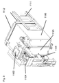
- Fig. 2 shows the lower part (1100) of a module of an analyzer.
- Lower part (1100) comprises a frame (1110).
- the processing plate comprises a station for presenting a reagent cassette (1102).
- the housing of a stacker unit is also shown (1103).
- the stacker unit further comprises a reagent drawer (1104) into which reagent cassettes are loaded.
- An elevator (1105) then moves the cassette to a level where it can be transferred into the reagent store (1106).
- the elevator comprises a Y handler (1105) and a Z-axis (1108).
- the spindle (1109) of the elevator (1105) is also shown.
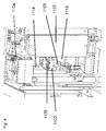
- the store (1106) and the back door (1112) as well as the cooling unit (1115) is shown in Fig. 3 .
- Fig. 4 shows the reagent cassette drawer (1104), the open front door (1125) of the reagent store (1106) and a reagent cassette (1122) comprising reagent inserts (1130).
- the reagent cassette (1102) is positioned on the Y handler (1105).
- the Y handler (1105) is about to place the reagent cassette (1102) into the store (1106).
- the interior of the store (1106) comprises turn tables (1113) on which reagent cassettes (1102) are placed and can be positioned.
- the turn tables (1113) comprise centering blocks (1114) in which the cassettes (1102) are positioned.
- a preferred number of centering blocks (1114) is 4 blocks (1114).
- An automated analyzer (400) for use in performing a nucleic acid based amplification reaction is shown in Fig. 12 .
- Said analyzer comprises a plurality of modules (401, 402, 403).
- One module is a processing module disposed at a first location within the analyzer constructed and arranged to separate a nucleic acid from other material in a sample.
- Said processing module comprises a separation device as herein described.
- the analyzer further comprises an amplification module disposed and arranged at a second location within the analyzer.
- the amplification module comprises a temperature-controlled incubator for incubating the contents of at least one receptacle, preferably of a multiwell plate comprising the separated nucleic acid and one or more amplification reagents for producing an amplification product indicative of the target nucleic acid in the sample.
- a preferred analytical system (440) for processing an analyte comprises, according to Fig. 10 ,
- the position of said pipetting units (702) of the first pipetting device (700) are variable. Preferred embodiments of said first pipetting device (700) are described hereinafter.
- the tip rack (70) comprises pipette tips (3, 4) in an ax(nxm) arrangement.
- a first type (4) and a second type (3) of pipette tips are comprised in the tip rack (70).
- the first type of pipette tips (4) is arranged in an nxm arrangement
- the second type of pipette tips (3) is arranged in the nxm arrangement.
- the first type of pipette tips (4) has a different volume than the second type of pipette tips (3), most preferably, the volume of the first type of pipette tips (4) is more than 500 ul, and the volume of the second type of pipette tips (3) is less than 500 ul.
- a 2.
- embodiments of the invention with more than two types of pipette tips, and thus a >2 are also included in the present invention.
- the analytical system (440) of the present invention comprises a control unit (1006) for allocating sample types and individual tests to individual positions of said processing plate (101).
- said positions are separate cells (401, 402).
- the system additionally comprises a transfer system (480) for transferring said process plate (101) and said rack (70) between first (402) and second (401) positions.
- a transfer system (480) for transferring said process plate (101) and said rack (70) between first (402) and second (401) positions.
- Preferred embodiments of said transfer system (480) are conveyor belts or, more preferably, one or more handler. Preferred embodiments of said handler are described hereinafter.
- said pipette units of said second pipetting device (35) are engaged to pipette tips (3, 4) which were used in the first position (402).
- a preferred embodiment of the system (440) of the present invention additionally comprises a third station (403) comprising a temperature-controlled incubator for incubating said analyte with reagents necessary to obtain a detectable signal.
- third station (403) is a amplification station comprising a thermoblock.
- More optimal control of the allocation of samples and tests to the nxm arrangement is achieved with a first processor (1004) which is comprised in said first position (402) to which said control unit (1006) transfers instructions for allocating sample types and individual tests to specific positions in the nxm arrangement of vessels (103) of the process plate (101), and a second processor (1005) which is comprised in said second position (401) to which said control unit (1006) transfers instructions for allocating sample types and individual tests to specific positions in the nxm arrangement of vessels (103) of the process plate.
- a first processor (1004) which is comprised in said first position (402) to which said control unit (1006) transfers instructions for allocating sample types and individual tests to specific positions in the nxm arrangement of vessels (103) of the process plate (101)
- a second processor (1005) which is comprised in said second position (401) to which said control unit (1006) transfers instructions for allocating sample types and individual tests to specific positions in the nxm arrangement of vessels (103) of the process plate.
- said system additionally comprises a first processor located in said first position, and a second processor located in said second position.
- said first processor (1004) controls said first pipetting device (700) and said second processor (1005) controls said second pipetting device (35).
- the present invention relates to an automated analyzer for isolating and/or analyzing an analyte which comprises a unit for transferring a liquid comprising a station for presenting at least one reagent cassette to a pipetting device.
- the analyzer additionally comprises a unit for analyzing an analyte.
- the analyzer also comprises a unit for temporary storage of at least one reagent cassette comprising reagents necessary to isolate and/or analyze said analyte.
- the unit for transferring a liquid additionally comprises at least one station for isolating an analyte. Exemplary embodiments for said station for isolating an analyte are described herein.
- the unit for transferring a liquid and the unit for temporary storage of at least one reagent cassette preferably overlap at least partially.
- said station for presenting at least one reagent cassette to a pipetting device is located within said overlapping area. It is understood that said unit for transferring a liquid comprises at least one pipetting device.
- the unit for transferring a liquid additionally comprises at least one station for isolating an analyte.
- the analyzer additionally comprises a unit for transferring a sample comprising an analyte from a first receptacle to a second receptacle.
- the analyzer additionally comprises a closed reagent store.
- the unit for temporary storage comprises a cooling unit. Further preferred embodiments of said temporary storage unit are disclosed below.
- the cooling unit of said closed reagent store is set to keep the insider temperature of the closed reagent store between a lower specified temperature and an upper specified temperature. Preferred embodiments of said temperatures are disclosed hereinafter.
- the closed reagent store is particularly useful since it provides for long term storage of temperature sensitive reagents.
- reagents include, but are not limited to, reagents comprising enzymes, such as polymerases for amplifying nucleic acids, or enzymes for color reactions.
- the combination of a reagent store for long term storage of reagents and a temporary store according to the present invention is particularly advantageous in an analytical system. This reduces the time during which a reagent cassette and its contents are exposed to temperatures above the storage temperatures to a minimum. In such an analyzer and system, reagent cassettes with reagents can be loaded less frequently, thus increasing walk-away time for the operator.
- the reagent cassettes are presented to the pipetting device more quickly than if they had to be transferred directly from the reagent store. It allows for placing the reagent store in an area of the analyzer where space is readily available.
- the dimensions of the temporary storage unit can be reduced to the space necessary to store reagent cassettes required for a current run, thus making it possible to place it in close proximity of the unit for transferring liquids while minimizing the space occupied by the temporary storage unit.
- This setup is particularly advantageous for a quick and timely presentation of the reagent cassettes to the pipetting device when the respective reagents are needed.
- the temporary store has further advantages. It preferably comprises a closed cooling area with a cooling unit.
- said cooling is an active cooling unit.
- the cooling unit is set to keep the temperature below a threshold temperature.
- the threshold temperature is 40°C, more preferably 35°C or 30°C, most preferably 28°C.
- the cooling unit only has to operate to keep the temperature below such threshold.
- less energy is required than for the reagent store.
- the lifetime of the reagents is optimized because they only are kept in the temporary store as long as they are needed, and are then returned to the reagent store for long-term storage. The exposure to elevated temperature is thus minimized while quick and timely presentation of the reagent cassettes to the pipetting device is maintained.
- the analyzer additionally comprises a handler system for bidirectional transport of said reagent cassette between said closed reagent store and said station for presenting a reagent cassette. Further preferred embodiments are described herein.
- the present invention also relates to a method of presenting a reagent cassette comprising reagents for analyzing an analyte to a pipetting device within an automated analyzer, comprising the steps of:
- steps b) to d) are repeated at least once.
- said reagent cassette is transferred from said closed reagent store to said temporary storage unit with a handler system.
- said reagent cassette is transferred from said closed reagent store to a first position with a first handler, and from said first position to the temporary store with a second handler.
- the reagent cassettes preferably comprise a tag for storing information, and wherein information of onboard time of the automated analyzer is stored on said tag.
- the method hereinbefore described additionally comprises the step of transferring said reagent cassette to said closed reagent store for long term storage until the reagent comprised in said reagent cassette is required for a new test, if said reagent cassette is not empty, or transferring said reagent cassette to a consumable waste station.
- the reagent cassettes are additionally preferably manually loaded into a drawer of said closed reagent store, wherein said reagent cassette is automatically transferred within said closed reagent store.
- Fig.5 shows a lower part (1149) of a module of an analyzer, preferably a processing module (402) ( Fig. 10 ).
- the top of the lower part (1149) is a processing plate (1150).
- the lower part further comprises a frame (1157).
- a stacker (1151) is also shown.
- the processing plate (1150) comprises a station (1156) for presenting a reagent cassette (1122) (shown eg in Fig. 4 ) to a pipetting device and an elevator plate (1152) inside said station for presenting a reagent cassette (1122) to a pipetting device (1156).
- the elevator plate (1156) can be moved in Z direction.
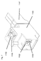
- FIG. 6 shows a temporary store (1153), the station for presenting a reagent cassette to a pipetting device (1156), and an emergency door (1154) for unloading the store and an air outlet (1147).
- Fig. 7 shows features as Fig. 6 , except that the emergency door (1154) is removed and a holding unit (1155) for holding cassettes (1102) inside the temporary store (1153) and a cassette (1122) can be seen.
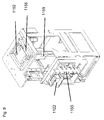
- the inside of the temporary store is shown in Figs 8 and 9 .
- Fig. 8 shows a frame (1158), holding unit (1155), reagent cassette (1122) held in a holding unit, a station (1156) for presenting a reagent cassette (1122) and an elevator plate (1156).
- Fig. 9 also shows the elevator (1159).
- a method for isolating and analyzing an that may be present in a fluid sample is analyte comprises the automated steps of
- said pipette tip used in step a) is re-used after step a).
- step a) may further comprise
- the processing vessel may comprise more than one receptacle. More preferably, the processing vessel is a multiwell plate.
- the method preferably additionally comprises the step of
- the washing in step d) comprises aspirating and dispensing the washing buffer with a process head engaged to pipette tips.
- receptacle as used herein relates to a single vessel (or tube) or to a tube comprised in a multi-tube unit, or to a well (or vessel) of a multiwell plate.
- vessel is understood to mean a single vessel or a single vessel in a multi-tube unit, a multiwell plate or a multi-tube unit or a well of a multiwell plate.
- the reacting comprises generating a detectable signal. More preferably, the method additionally comprises the step of detecting a detectable signal.
- reacting as used herein relates to any type of chemical reaction of the analyte with reagents that is necessary to obtain a detectable signal.
- said reacting comprises amplification.
- Amplification may be understood as any type of enhancement of a signal.
- amplification can be a conversion of a molecule by an enzyme, wherein said enzyme is coupled or bound to the analyte, leading to a detectable signal, wherein more signal molecules are formed than analyte molecules are present.
- amplification further relates to nucleic acid amplification, if the analyte is a nucleic acid. This includes both linear, isothermal and exponential amplifications.
- nucleic acid amplification methods are TMA, SDA, NASBA, PCR, including real-time PCR. Such methods are well known to the skilled person.
- solid support as used herein relates to any type of solid support to which the analyte is capable of binding, either directly and non-specifically by adsorption, or indirectly and specifically.
- Indirect binding may be binding of an analyte to an antibody immobilized on the solid support, or binding of a tag to a tag binding compound, e.g. binding of 6xHis tags to Nichelate.
- the analyte is a nucleic acid
- such indirect binding is preferably by binding to a capture nucleic acid probe which is homologuous to a target sequence of the nucleic acid of interest.
- a target analyte preferably a target nucleic acid
- non-target material preferably non-target nucleic acid
- capture probe is immobilized on the solid support.
- Solid support material may be a polymer, or a composition of polymers. Other types of solid support material include magnetic silica particles, metal particles etc.
- Preferred non-specific binding of nucleic acid to silica particles occurs in the presence of chaotropic compounds. Such binding may also be referred to as direct binding, as opposed to the indirect binding described above.
- the solid supports silica particles which comprise a magnetic or magnetizable material.
- the transporting of said rack comprising said pipette tips and said processing vessel to a second positions occurs between a separate first cell of an analytical instrument and a separate second cell, preferably a processing cell, of said analytical system.
- the rack comprises independent chambers to accommodate pipette tips.
- the first type of pipette tips is re-used for the washing in step d).
- the rack additionally comprises a second type of pipette tips.
- a method as hereinbefore described wherein between step d) and e), the analyte is eluted from the magnetic particles.
- a preferred embodiment comprises the transfer of the analyte from said processing vessel, which is preferably a multiwell plate, to a reaction vessel, which is preferably a multiwell plate, with said second type of pipette tips.
- the present disclosure describes an analytical system for isolating an analyte, said system comprising
- the positions are separate cells.
- the rack transferred by said transfer system preferably comprises pipette tips which were used in the first position.
- the first receptacle is a sample vessel and the second receptacle is a processing vessel. Further preferred is a processing vessel which is a multiwell vessel. Preferred embodiments of said stations are described hereinafter.
- the transport system preferably transfers the receptacle and the rack from the first position to the second separate position.
- the second separate position comprises a magnetic separation station.
- the analytical system additionally preferably comprises an amplification station.
- the transport system of the preferred system comprises a handler constructed and arranged to grip and transport said rack and said processing vessel from a first to a second location within the system. Further preferred handlers are disclosed herein.
- the system is preferably fully automated.
- the present disclosure also relates to an automated analyzer for isolating and analyzing an analyte comprising a plurality of stations disposed within said analyzer.
- the plurality of stations comprises a sample dispensing station disposed in a first location.
- said sample dispensing station is constructed and arranged to dispense liquid sample comprising an analyte from a sample vessel to a processing vessel with pipette tips held in a rack.
- Further preferred sample dispensing stations are stations comprising a sample vessel, a processing vessel and a liquid dispensing unit. Said liquid dispensing unit is preferably a process device.
- the automated analyzer further comprises a separation station disposed in a second location.
- said separation station is constructed and arranged to receive said processing vessel holding said liquid sample and said rack holding pipette tips used in the sample dispensing station and to separate an analyte from other material present in the liquid sample.
- Another preferred embodiment of a separation station is a separation station comprising movable magnets.
- the automated analyzer further comprises a reaction station disposed in a third location, wherein said reaction station is constructed and arranged to analyze said analyte to obtain a detectable signal.
- a reaction station is a station comprising an incubator.
- said incubator is a temperature-controlled incubator. More preferably, said incubator is held at one constant temperature.
- Another preferred embodiment of an incubator is a thermocycler block.
- a detector for detecting the detectable signal is integrally connected to the reaction station, more preferably to the incubator as hereinbefore described.
- a preferred detector comprises a nucleic acid quantification system for periodic measurement and quantification. More preferably, the detector additionally comprises a nucleic acid detection system which detects the signal and ascertains the presence or absence of the nucleic acid in the reaction receptacle based upon whether or not a signal above a threshold level is detected.
- the automated analyzer additionally comprises a detecting station.
- the automated analyzer further comprises a transport mechanism.
- Said transport mechanism comprises a handler for handling consumables.
- Said handler preferably transports a consumable between stations.
- said transport mechanism is constructed and arranged to transport said sample vessel and said rack from said sample dispensing station to said separation station.
- the analytical apparatus (400) of the present disclosure comprises at least one module (401) for processing an analyte, said processing comprising pipetting of a liquid.
- the processing module (401) comprises:
- said processing module (401) is a module for isolation and purification of an analyte. Therefore, the term "processing" as used herein is understood to relate to isolation and/or separation and/or capture and/or purification of an analyte.
- said apparatus (400) comprises a module for preparing samples for processing (402).
- said apparatus (400) comprises a module for amplification of said analyte (403).
- said apparatus additionally comprises a module (404) for transferring amplification reagents from a storage receptacle to a receptacle comprising a purified analyte. Further preferred embodiments of said apparatus are as hereinbefore and hereinafter described.
- the present disclosure also relates to an automated analyzer (400) for use in performing a nucleic acid based amplification reaction, said analyzer comprising a plurality of modules (401, 402, 403).
- One module is a processing module disposed at a first location within the analyzer constructed and arranged to separate a nucleic acid from other material in a sample.
- Said processing module comprises a separation device as herein described.
- the analyzer further comprises an amplification module disposed and arranged at a second location within the analyzer.
- the amplification module comprises a temperature-controlled incubator for incubating the contents of at least one receptacle, preferably of a multiwell plate comprising the separated nucleic acid and one or more amplification reagents for producing an amplification product indicative of the target nucleic acid in the sample.
- the present disclosure also relates to an analytical system comprising a holding station and a multiwell plate set as described herein.
- said multiwell plate set is fixed in said holding station.
- the multiwell plate comprises a base with a rim which comprises recesses, wherein a positioning and fixing element, preferably a latch-clip (Fig. 47 a) and b)), on said holding station contacts said recesses, wherein said contact exerts a downwards pressure on the base of the multiwell plate, thereby fixing the multiwell plate in the holding station.
- a positioning and fixing element preferably a latch-clip (Fig. 47 a) and b)
- the present disclosure also relates to an analytical instrument comprising:
- the analytical instrument preferably additionally comprises a liquid handling module (404, 500). Further embodiments and preferred embodiments of the analytical instrument are described herein, either separately or as combinations of embodiments. Preferred embodiments of analyzers are shown in Figs. 38 and 51.
- the analytical instrument according to the present disclosure preferably additionally comprises a sealing station (410).
- the sealing station (410) is preferably located in the process module (401).
- module and “cell” are used interchangeably herein.
Abstract
The invention relates to an automated analyzer with an on-board fridge for long-term cooling of reagents, and for a method for isolating and analyzing an analyte comprising long-term cooling of reagents.
Description
- The present invention relates to an automated analyzer and an automated system for detecting or quantitating analytes and a method for detecting or quantitating an analyte in a sample.
- Automated analyzers are commonly used diagnosing conditions in individuals, or for testing pools of samples from one or multiple individuals. For analyzing an analyte in a sample, reagents are required. Such reagents have to be provided to the analyzer and distributed within the analyzer. Therefore, reagents are commonly kept in reagent cassettes which can be loaded or unloaded into or from the analyzer. Frequently, such reagents are temperature sensitive. In some analyzers, reagents are only loaded for a single load and then manually retrieved and transferred into a refrigerator. Analyzers are also known with onboard cooled storage.
- The present invention provides for improved automated analyzers, systems and methods comprising cooled storage of reagents.
- The present invention relates to an automated analyzer for isolating and/or analyzing an analyte. The analyzer of the present invention comprises a unit for transferring a liquid. This unit comprises a station for presenting a reagent cassette to a pipetting device. The analyzer further comprises a unit for isolating said analyte. Furthermore, the analyzer comprises a closed reagent store for storing reagents. Such reagents preferably comprise reagents necessary for performing the analysis. The closed reagent store comprises a cooling unit for active cooling. Furthermore, it comprises an internal storage and retrieval unit. In order to allow input and output of reagent cassettes, a closure is comprised in the closed reagent store. The closed reagent store also comprises an identification unit for identifying the contents of a reagent cassette. For automated transport of the reagent cassettes between the closed reagent store to other stations of the analyzer and back to the reagent store, the analyzer also comprises a handler system for bidirectional transport of said reagent cassette between said reagent store and said station for presenting a reagent cassette.
- The analyzer of the present invention allows the operator of the analyzer to load reagents for long-term storage. This increases the walk-away time for the operator since the automated analyzer can run for longer periods of time without need for re-loading of reagents before, during or after every analytical run. The onboard cooled reagent store also allows the uncoupling of loading and unloading of reagents from the operation of the analyzer.
- The present invention also relates to a method for providing reagents to an analytical system comprising the steps of:
- loading reagent cassettes into a reagent store;
- identifying said cassettes;
- automatically transferring said cassettes into said reagent store;
- positioning said cassettes within said reagent store;
- transferring instructions from a control unit to said reagent store, wherein said instructions specify which cassettes are required by the system;
- providing said cassettes to a handler system;
- transporting said cassettes with said handler system to a station for presenting said cassettes to the system;
- returning said cassette to said reagent store or transferring said cassette to a waste station.
- This method allows for returning partly used reagent cassettes to the cooled reagent store until further use. The life time of the reagents can, thus, be prolonged, and reagents in a cassette can be used until the cassette is empty.
-
-
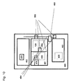
Fig. 1 Workflow of reagent cassettes in analyzer comprising reagent stores. -
Fig. 2 View of lower part of analyzer module with stacker and reagent store. -
Fig. 3 Closed reagent store -
Fig. 4 View of loading of reagent cassette into reagent store -
Fig. 5 View of lower part of analyzer module with stackers and temporary store -
Fig. 6 View of outside of temporary store -
Fig. 7 view of temporary store with open emergency door -
Fig. 8 storage and retrieval system of temporary store -
Fig. 9 storage and retrieval system of temporary store with reagent cassette -
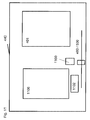
Fig. 10 first schematic view of analytical system -
Fig. 11 second schematic view of analytical system -
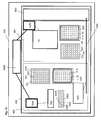
Fig. 12 third schematic view of analytical system - The present invention relates to an automated analyzer for isolating and/or analyzing an analyte.
- The terms "analytical apparatus"(400) and "analyzer" (400) and "analytical instrument" (400) are used interchangeably. An analytical system comprises an analyzer. An analyzer comprises one or more modules or cells or units. Said modules or cells or units comprise stations for carrying out the processing and/or analysis of an analyte.
- The term "analyte" as used herein may be any type of biomolecule which is of interest for detection, and the detection thereof is indicative of a diagnostic status of an organism. The organism can be animal or, more preferably, human. Preferred analytes are proteins, polypeptides, antibodies or nucleic acids. More preferably, the analyte is a nucleic acid. The analyte may be present in a liquid sample, or it may be present as a solid sample affixed to a support. Solid samples may include tissue.
- The term "detecting" as used herein relates to qualitative measurement of an analyte.
- The analyzer of the present invention comprises a unit for transferring a liquid.
- The term "liquid" as used herein relates to any type of liquid which has to be transferred during an analytical process. Thus, the term includes liquid samples. It also includes reagents or suspensions of reagents.
- The unit for transferring liquids comprises a station for presenting a reagent cassette to a pipetting device. In one preferred embodiment, said unit is a unit or cell or module in which reagents are transferred from said reagent cassette to at least one receptacle. In a more preferred embodiment, said unit comprises a pipetting device for transferring samples from a sample vessel to at least one receptacle, and for transferring control reagents to said at least one receptacle. Preferred embodiments of pipetting devices, reagent cassettes, receptacles and control reagents are further described hereinafter. In one preferred embodiment, said unit for transferring liquids is a unit for preparing a reaction mixture. In such a unit, reagents are added to an analyte prior to reaction. A reagent cassette can refer to a container comprising a liquid or suspension of reagents. Or a reagent cassette can be a holder for holding containers comprising a liquid or a suspension of reagents.
- In one embodiment, the analyzer further comprises a unit for isolating said analyte. Preferably, said unit for isolating said analyte and said unit for transferring liquids are located on a processing deck, and more preferably, said closed reagent store is located below said processing deck. A preferred embodiment is also comprised wherein the unit for transferring liquids and the unit for isolating said analyte are merged into one unit.
- In a further preferred embodiment, the analyzer additionally comprises a unit for reacting said analyte to obtain a detectable signal. In a more preferred embodiment, said unit for reacting said analyte to obtain a detectable signal also comprises a detection unit. In another more preferred embodiment, said analyzer additionally comprises a separate detection unit.
- The term "processing deck" as used herein relates to a deck on which samples are processed. The processing deck may be one deck on which all stations necessary for processing are located. In a system comprising more than one module, the term "processing deck" includes all the decks within the different modules which comprise stations for processing a sample. Thus, the term "processing deck" may also include the different decks in different modules of an analyzer.
- In another preferred embodiment, said unit for transferring liquids comprises a separation station for isolating and purifying an analyte. In a preferred embodiment, the station for presenting a reagent cassette to a pipetting device is also disposed on said processing deck. More preferably, the closed reagent store is disposed at a lower level, most preferably below said processing deck. Thus, in a preferred embodiment, the closed reagent store and the station for presenting a reagent cassette to a pipetting device are separate. One advantage is that the space of the analyzer can be used in an optimal way by also using space underneath the processing deck.
- Furthermore, the analyzer comprises a closed reagent store for storing reagent cassettes. A closed reagent store is understood to relate to an incubator with a casing, wherein said casing is insulated from the environment and comprises a closure which allows opening and closing the incubator to add or retrieve reagent cassettes. Preferred embodiments of closures are doors or shutters or, more preferably, a drawer. Said reagent store may additionally be suitable for storing other containers comprising reagents.
- Reagents preferably comprise reagents necessary for performing the analysis. Reagents necessary for performing the analysis of analytes include reagents for sample preparation, control reagents, reagents for reacting with the analyte to obtain a detectable signal, and/or reagents necessary for detecting the analyte. Such reagents may include reagents for isolating an analyte and/or reagents for processing a sample and/or reagents for reacting with an analyte to obtain a detectable signal and/or washing reagents and/or diluents.
- The closed reagent store comprises a cooling unit for active cooling. The term "active cooling" is understood to mean that the incubator is kept within a predefined range of temperatures. A preferred range of temperatures is between -4°C, preferably -2° or 0°C or 2°C to 10 °C, preferably 8°C or 6°C or 4°C.
- Furthermore, it comprises an internal storage and retrieval unit. The preferred internal storage and retrieval system comprises a transport mechanism, preferably an elevator, for transporting a reagent cassette into the reagent store, and storage positions, preferably at least one turntable which preferably comprises centering blocks for positioning reagent cassettes. The elevator preferably comprises a Y-handler.
- In order to allow input and output of reagent cassettes, a closure is comprised in the closed reagent store.
- The closed reagent store also comprises an identification unit for identifying the contents of a reagent cassette.
- For automated transport of the reagent cassettes between the closed reagent store to other stations of the analyzer and back to the reagent store, the analyzer also comprises a transport system for bidirectional transport of said reagent cassette between said reagent store and said station for presenting a reagent cassette. Said system for bidirectional transport may comprise conveyors. In a preferred embodiment, said transport system comprises at least one handler. More preferably, said handler system comprises at least two, preferably at least three handlers.
- Handlers and pipetting devices are well known in the art.
- In one preferred embodiment of the analyzer described herein, the analyzer comprises a control unit for transferring instructions to said closed reagent store, wherein said instructions specify the reagent cassette required by the system. Such control units preferably comprise processors and are known to the skilled person.
- In one preferred embodiment, the store and the temporary store are comprised on the same module of an analyzer. In another preferred embodiment, they are comprised on different modules of an analyzer. In one preferred embodiment, the analyzer is a self-contained analyzer with comprising stations within an open space devoid of any spatial separation.
- The present invention also relates to a method of providing reagents to an analytical system comprising the steps of:
- loading reagent cassettes onto a loading interface of a reagent store;
- identifying said reagent cassettes;
- transferring said reagent cassettes into said reagent store;
- positioning said reagent cassettes within said reagent store;
- transferring instructions from a control unit to said reagent store, wherein said instructions specify which reagent cassettes are required by the system;
- providing a reagent cassette to a transport system;
- transporting said reagent cassette with said transport system to a station for presenting said reagent cassette to a pipetting device;
- returning said reagent cassette to said reagent store or transferring said reagent cassette to a waste station.
- A loading interface is an interface associated with the closure hereinbefore described which receives the reagent cassettes loaded by the operator, a preferred embodiment is the drawer hereinbefore described. Preferably, the operator manually loads the reagent cassettes into the drawer of the closed reagent store. The drawer then automatically closes. The reagent cassettes are identified. In a preferred embodiment, all steps after loading and before retrieval of reagent cassettes are automated.
- In a preferred embodiment of the method described above, the reagent store is a closed reagent store as described hereinbefore. Thus, said closed reagent store is preferably cooled by an active cooling unit. In a preferred embodiment, said positioning of said cassettes within said store and said providing of said cassettes is performed by an internal storage and retrieval unit.
- In a preferred embodiment of the method hereinbefore described, said reagent cassettes comprise at least one tag for reading and writing information. Preferably, said method comprises storing onboard time on said tag. More preferably, said storing of onboard time on said tag is done when providing said cassettes from said store to said handler system. In one preferred embodiment, said storing of onboard time comprises writing of a time stamp on said tag.
- Thus, in a preferred embodiment, the method additionally comprises determining and storing onboard time. More preferably, said determining and storing onboard time is triggered when providing said reagent cassette from said store to said transport system. Most preferably, said storing of onboard time is done with a decremental counter before returning said reagent cassette to said reagent store. Further preferred embodiments are described herein.
- Thus, in one embodiment, said storing of onboard time comprises storing of onboard time with a counter, preferably a decrementing counter. Preferably, the speed of the decrementing counter is increased with increased temperature. Thus, the speed of the decrementing counter is preferably related, more preferably proportional to the difference between the temperature of the area of the presence of the reagent cassette and the reagent store for long term storage. For the embodiment of the onboard time stamp, preferably, said time stamp is then compared with the actual time, an on-board time is calculated based on said time stamp and the actual time, and a cumulated onboard time is calculated and written on said tag before returning said cassette to said reagent store.
- It is understood that whenever a process step is described herein which relates to writing an onboard time stamp to track onboard time, the same process step can be replaces with determining onboard time using a counter, preferably a decremental counter. An incremental counter is an alternative for counting onboard time.
- The term "actual time" is understood to be the time when the respective process step is carried out.
- Once reagents are presented to a pipetting device, said reagents are preferably transferred from said reagent cassette held in said station for presenting said reagent cassette to at least one receptacle by a pipetting device.
- A preferred workflow for the method hereinbefore described is described in more detail in
Fig. 1 . Reagent cassettes comprise a tag for storing information. Said information preferably comprises information about on-board time, preferably on-board time in different temperature compartments. Preferably, said tag is an RFID tag. Reagent cassettes are loaded onto the analyzer and stored in the reagent store described herein. A loading flag is written onto the tag upon loading to store the loading date. The control system stores information on the type of reagent or reagents stored in a reagent cassette and the location of the reagent cassette within the store. Upon receipt of information regarding reagents which are required by the analytical system, the handler system retrieves and transports the required cassette or cassettes to a station for presenting a reagent cassette to the analyzer. A counter on the tag is now triggered to decrementally count during time spent outside the reagent store. Alternatively, an onboard time stamp may be written onto the tag. The reagent cassette is now transported either to a station for presenting a reagent cassette to a pipetting device or to the temporary reagent store herein described. If the reagent cassette is transported to a station for presenting a reagent cassette to a pipetting device, the reagent cassette is either returned to the reagent store after use, or is transferred to a waste station. If the reagent cassette is transferred back to the reagent store, an onboard time stamp may be written on the tag. The process may then be repeated. - If the reagent cassette is transported to the temporary store, an onboard time stamp may written onto the tag before placing the reagent cassette in the temporary store, if a time stamp is used to monitor on-board time. With the counter, the decremental counting occurs according to the temperature in the temporary store. The location of the cassette in the temporary store is stored by the control system. If the system requires reagents, the corresponding reagent cassette is transferred to a station for presenting a reagent cassette to a pipetting device. The advantage of the temporary store is that a reagent cassette can be presented to the pipetting device very quickly. While the reagent cassette is located on the station for presenting a reagent cassette, the counter counts faster than in the temporary store if the temperature on the station for presenting a reagent cassette is higher than in the temporary store. The reagent cassette may be returned to the temporary store for re-use or to the reagent store for long time storage. An on-board time stamp is written onto the tag prior to storage in the reagent store. An onboard time counter is updated. The reagent cassette is then stored in the reagent store until it is required again.
- If total onboard time exceeds a preset value, if reagent levels in the reagent cassette are too low or if the reagent cassette is erroneous, it is transported to a waste station or to an input/output position for manual removal.
- The analytical system herein described, thus, preferably comprises a reading/writing device (1160) (as shown in
Fig. 11 ). - Also within the scope of the present invention are analyzers and systems for isolating and/or analyzing an analyte as described hereinbefore and hereinafter, which comprise a reagent store as described herein.
- Furthermore, a method for analyzing an analyte in a system comprising a reagent store as described hereinbefore is also within the scope of the present invention.
- A method for isolating and analyzing an analyte that may be present in a liquid sample is disclosed. Said method comprises the automated steps of
- a) transferring said liquid sample from a sample vessel to a processing vessel with a pipette tip;
- b) combining together a solid support material and said liquid sample in a well of said processing vessel for a period of time and under conditions sufficient to permit said analyte to be immobilized on the solid support material ;
- c) isolating the solid support material from other material present in the liquid sample in a separation station;
- d) and purifying the analyte in the separation station by separating the liquid sample from the solid support material and washing the materials one or more times with a wash buffer.
- Preferably, the processing vessel may comprise more than one receptacle. More preferably, the processing vessel is a multiwell plate. The method preferably additionally comprises the step of
- e) reacting said purified analyte with reagents necessary to obtain a detectable signal.
- The term "receptacle" as used herein relates to a single vessel (or tube) or to a tube comprised in a multi-tube unit, or to a well (or vessel) of a multiwell plate.
- The term "vessel" is understood to mean a single vessel or a single vessel in a multi-tube unit, a multiwell plate or a multi-tube unit or a well of a multiwell plate.
- In a preferred embodiment, the reacting comprises generating a detectable signal. More preferably, the method additionally comprises the step of detecting a detectable signal.
- The term "reacting" as used herein relates to any type of chemical reaction of the analyte with reagents that is necessary to obtain a detectable signal. Preferably, said reacting comprises amplification. Amplification may be understood as any type of enhancement of a signal. Thus, amplification can be a conversion of a molecule by an enzyme, wherein said enzyme is coupled or bound to the analyte, leading to a detectable signal, wherein more signal molecules are formed than analyte molecules are present. One such non-limiting example is a formation of a chemiluminescent dye, e.g. using ECL. The term amplification further relates to nucleic acid amplification, if the analyte is a nucleic acid. This includes both linear, isothermal and exponential amplifications. Non-limiting examples of nucleic acid amplification methods are TMA, SDA, NASBA, PCR, including real-time PCR. Such methods are well known to the skilled person.
- The term "solid support" as used herein relates to any type of solid support to which the analyte is capable of binding, either directly and non-specifically by adsorption, or indirectly and specifically. Indirect binding may be binding of an analyte to an antibody immobilized on the solid support, or binding of a tag to a tag binding compound, e.g. binding of 6xHis tags to Nichelate. When the analyte is a nucleic acid, such indirect binding is preferably by binding to a capture nucleic acid probe which is homologuous to a target sequence of the nucleic acid of interest. Thus, using capture probes attached on a solid support, a target analyte, preferably a target nucleic acid, can be separated from non-target material, preferably non-target nucleic acid. Such capture probe is immobilized on the solid support. Solid support material may be a polymer, or a composition of polymers. Other types of solid support material include magnetic silica particles, metal particles etc.
- Preferred non-specific binding of nucleic acid to silica particles occurs in the presence of chaotropic compounds. Such binding may also be referred to as direct binding, as opposed to the indirect binding described above. Preferably, the solid supports silica particles which comprise a magnetic or magnetizable material.
-
Fig. 2 shows the lower part (1100) of a module of an analyzer. On top is a processing plate (1101). Lower part (1100) comprises a frame (1110). The processing plate comprises a station for presenting a reagent cassette (1102). The housing of a stacker unit is also shown (1103). The stacker unit further comprises a reagent drawer (1104) into which reagent cassettes are loaded. An elevator (1105) then moves the cassette to a level where it can be transferred into the reagent store (1106). The elevator comprises a Y handler (1105) and a Z-axis (1108). The spindle (1109) of the elevator (1105) is also shown. Also visible is an arrangement (1111) for opening a back door of the store (1106). The store (1106) and the back door (1112) as well as the cooling unit (1115) is shown inFig. 3 . -
Fig. 4 shows the reagent cassette drawer (1104), the open front door (1125) of the reagent store (1106) and a reagent cassette (1122) comprising reagent inserts (1130). The reagent cassette (1102) is positioned on the Y handler (1105). The Y handler (1105) is about to place the reagent cassette (1102) into the store (1106). The interior of the store (1106) comprises turn tables (1113) on which reagent cassettes (1102) are placed and can be positioned. The turn tables (1113) comprise centering blocks (1114) in which the cassettes (1102) are positioned. A preferred number of centering blocks (1114) is 4 blocks (1114). - An automated analyzer (400) for use in performing a nucleic acid based amplification reaction is shown in
Fig. 12 . Said analyzer comprises a plurality of modules (401, 402, 403). One module is a processing module disposed at a first location within the analyzer constructed and arranged to separate a nucleic acid from other material in a sample. Said processing module comprises a separation device as herein described. The analyzer further comprises an amplification module disposed and arranged at a second location within the analyzer. The amplification module comprises a temperature-controlled incubator for incubating the contents of at least one receptacle, preferably of a multiwell plate comprising the separated nucleic acid and one or more amplification reagents for producing an amplification product indicative of the target nucleic acid in the sample. - A preferred analytical system (440) for processing an analyte comprises, according to
Fig. 10 , - a) a first position comprising first receptacles (1001) in linear arrangement comprising liquid samples (1010), a processing plate (101) comprising receptacles (103) in nxm arrangement for holding a liquid sample (1011), a first pipetting device (700) comprising at least two pipetting units (702) in linear arrangement, wherein said pipetting units (702) are coupled to pipette tips (3, 4), and a tip rack (70) comprising pipette tips (3, 4) in an ax(nxm) arrangement;
- b) a second position comprising a holder (201, 128) for said processing plate (101), a holder (470) for said tip rack (70) and a second pipetting device (35), said second pipetting device (35) comprising pipetting units (702) in an nxm arrangement for coupling to pipette tips (3, 4) (
Fig. 10 ). The term "holder" as used herein relates to any arrangement capable of receiving a rack or a processing plate. - The advantages of the analytical system (440) of the present invention are as described above for the method of the present invention.
- Preferably, the position of said pipetting units (702) of the first pipetting device (700) are variable. Preferred embodiments of said first pipetting device (700) are described hereinafter.
- In one embodiment, the tip rack (70) comprises pipette tips (3, 4) in an ax(nxm) arrangement. Preferably, a first type (4) and a second type (3) of pipette tips are comprised in the tip rack (70). In this embodiment, the first type of pipette tips (4) is arranged in an nxm arrangement, and the second type of pipette tips (3) is arranged in the nxm arrangement. More preferably, the first type of pipette tips (4) has a different volume than the second type of pipette tips (3), most preferably, the volume of the first type of pipette tips (4) is more than 500 ul, and the volume of the second type of pipette tips (3) is less than 500 ul. In this embodiment, a=2. However, embodiments of the invention with more than two types of pipette tips, and thus a >2 are also included in the present invention.
- In one aspect, the analytical system (440) of the present invention comprises a control unit (1006) for allocating sample types and individual tests to individual positions of said processing plate (101). Preferably, said positions are separate cells (401, 402).
- In one aspect of the invention, the system additionally comprises a transfer system (480) for transferring said process plate (101) and said rack (70) between first (402) and second (401) positions. Preferred embodiments of said transfer system (480) are conveyor belts or, more preferably, one or more handler. Preferred embodiments of said handler are described hereinafter.
- Furthermore, preferably said pipette units of said second pipetting device (35) are engaged to pipette tips (3, 4) which were used in the first position (402).
- A preferred embodiment of the system (440) of the present invention additionally comprises a third station (403) comprising a temperature-controlled incubator for incubating said analyte with reagents necessary to obtain a detectable signal. A further preferred embodiment of third station (403) is a amplification station comprising a thermoblock. More optimal control of the allocation of samples and tests to the nxm arrangement is achieved with a first processor (1004) which is comprised in said first position (402) to which said control unit (1006) transfers instructions for allocating sample types and individual tests to specific positions in the nxm arrangement of vessels (103) of the process plate (101), and a second processor (1005) which is comprised in said second position (401) to which said control unit (1006) transfers instructions for allocating sample types and individual tests to specific positions in the nxm arrangement of vessels (103) of the process plate.
- Preferably, said system additionally comprises a first processor located in said first position, and a second processor located in said second position.
- More preferably, said first processor (1004) controls said first pipetting device (700) and said second processor (1005) controls said second pipetting device (35).
- The present invention relates to an automated analyzer for isolating and/or analyzing an analyte which comprises a unit for transferring a liquid comprising a station for presenting at least one reagent cassette to a pipetting device. The analyzer additionally comprises a unit for analyzing an analyte. Furthermore, the analyzer also comprises a unit for temporary storage of at least one reagent cassette comprising reagents necessary to isolate and/or analyze said analyte.
- In one embodiment, the unit for transferring a liquid additionally comprises at least one station for isolating an analyte. Exemplary embodiments for said station for isolating an analyte are described herein. The unit for transferring a liquid and the unit for temporary storage of at least one reagent cassette preferably overlap at least partially. Preferably, said station for presenting at least one reagent cassette to a pipetting device is located within said overlapping area. It is understood that said unit for transferring a liquid comprises at least one pipetting device.
- In one aspect of the present invention, the unit for transferring a liquid additionally comprises at least one station for isolating an analyte. In a further preferred aspect of the present invention, the analyzer additionally comprises a unit for transferring a sample comprising an analyte from a first receptacle to a second receptacle. In a most preferred aspect of the present invention, the analyzer additionally comprises a closed reagent store.
- In a preferred embodiment of the analyzer, the unit for temporary storage comprises a cooling unit. Further preferred embodiments of said temporary storage unit are disclosed below.
- Preferred embodiments of said closed reagent store are described hereinafter. The cooling unit of said closed reagent store is set to keep the insider temperature of the closed reagent store between a lower specified temperature and an upper specified temperature. Preferred embodiments of said temperatures are disclosed hereinafter.
- The closed reagent store is particularly useful since it provides for long term storage of temperature sensitive reagents. Such reagents include, but are not limited to, reagents comprising enzymes, such as polymerases for amplifying nucleic acids, or enzymes for color reactions. The combination of a reagent store for long term storage of reagents and a temporary store according to the present invention is particularly advantageous in an analytical system. This reduces the time during which a reagent cassette and its contents are exposed to temperatures above the storage temperatures to a minimum. In such an analyzer and system, reagent cassettes with reagents can be loaded less frequently, thus increasing walk-away time for the operator. By transferring reagent cassettes from the reagent store to the temporary store, the reagent cassettes are presented to the pipetting device more quickly than if they had to be transferred directly from the reagent store. It allows for placing the reagent store in an area of the analyzer where space is readily available. The dimensions of the temporary storage unit can be reduced to the space necessary to store reagent cassettes required for a current run, thus making it possible to place it in close proximity of the unit for transferring liquids while minimizing the space occupied by the temporary storage unit. This setup is particularly advantageous for a quick and timely presentation of the reagent cassettes to the pipetting device when the respective reagents are needed.
- The temporary store has further advantages. It preferably comprises a closed cooling area with a cooling unit. Preferably, said cooling is an active cooling unit. The cooling unit is set to keep the temperature below a threshold temperature. Preferably the threshold temperature is 40°C, more preferably 35°C or 30°C, most preferably 28°C. The cooling unit only has to operate to keep the temperature below such threshold. Thus, less energy is required than for the reagent store. On the other hand, the lifetime of the reagents is optimized because they only are kept in the temporary store as long as they are needed, and are then returned to the reagent store for long-term storage. The exposure to elevated temperature is thus minimized while quick and timely presentation of the reagent cassettes to the pipetting device is maintained.
- Preferred embodiments of the closed reagent store are described further below.
- In one preferred aspect of the invention, the analyzer additionally comprises a handler system for bidirectional transport of said reagent cassette between said closed reagent store and said station for presenting a reagent cassette. Further preferred embodiments are described herein.
- The present invention also relates to a method of presenting a reagent cassette comprising reagents for analyzing an analyte to a pipetting device within an automated analyzer, comprising the steps of:
- transferring a reagent cassette stored in a closed reagent store with active cooling to a temporary storage unit;
- holding said reagent cassette in said temporary storage unit until it is needed by the analyzer;
- transferring said reagent cassette from said temporary storage unit to a station for presenting said reagent cassette to said pipetting device;
- transferring said reagent cassette back to said temporary storage unit when pipetting of the reagent is finished.
- Preferably, steps b) to d) are repeated at least once. In a preferred embodiment, said reagent cassette is transferred from said closed reagent store to said temporary storage unit with a handler system.
- In one preferred embodiment, said reagent cassette is transferred from said closed reagent store to a first position with a first handler, and from said first position to the temporary store with a second handler.
- The reagent cassettes preferably comprise a tag for storing information, and wherein information of onboard time of the automated analyzer is stored on said tag.
- In a preferred embodiment, the method hereinbefore described additionally comprises the step of transferring said reagent cassette to said closed reagent store for long term storage until the reagent comprised in said reagent cassette is required for a new test, if said reagent cassette is not empty, or transferring said reagent cassette to a consumable waste station. The reagent cassettes are additionally preferably manually loaded into a drawer of said closed reagent store, wherein said reagent cassette is automatically transferred within said closed reagent store.
- Further preferred embodiments are as described herein.
- Exemplary embodiments of the analyzer of the present invention and its components, in particular the temporary storage unit, are shown hereinafter.
-
Fig.5 shows a lower part (1149) of a module of an analyzer, preferably a processing module (402) (Fig. 10 ). The top of the lower part (1149) is a processing plate (1150). The lower part further comprises a frame (1157). A stacker (1151) is also shown. The processing plate (1150) comprises a station (1156) for presenting a reagent cassette (1122) (shown eg inFig. 4 ) to a pipetting device and an elevator plate (1152) inside said station for presenting a reagent cassette (1122) to a pipetting device (1156). The elevator plate (1156) can be moved in Z direction. Also shown is the temporary store (1153).Fig. 6 shows a temporary store (1153), the station for presenting a reagent cassette to a pipetting device (1156), and an emergency door (1154) for unloading the store and an air outlet (1147).Fig. 7 shows features asFig. 6 , except that the emergency door (1154) is removed and a holding unit (1155) for holding cassettes (1102) inside the temporary store (1153) and a cassette (1122) can be seen. The inside of the temporary store is shown inFigs 8 and9 .Fig. 8 shows a frame (1158), holding unit (1155), reagent cassette (1122) held in a holding unit, a station (1156) for presenting a reagent cassette (1122) and an elevator plate (1156). In particular,Fig. 9 also shows the elevator (1159). - A method for isolating and analyzing an that may be present in a fluid sample is analyte is disclosed. Said method comprises the automated steps of
- f) transferring said fluid sample from a sample vessel to a processing vessel with a pipette tip;
- g) combining together a solid support material and said fluid sample in a well of said processing vessel for a period of time and under conditions sufficient to permit said analyte to be immobilized on the solid support material ;
- h) isolating the solid support material from other material present in the fluid sample in a separation station;
- i) and purifying the analyte in the separation station by separating the fluid sample from the solid support material and washing the materials one or more times with a wash buffer.
- Preferably, said pipette tip used in step a) is re-used after step a).
- In the method hereinbefore described, step a) may further comprise
- a1) engaging pipette tips of a first type which are held in a rack in a first position with a first process head;
- a2) transferring said fluid sample from a sample vessel to a processing vessel with pipette tips of a first type engaged to a first process head;
- a3) placing said pipette tips in said rack and disengaging said pipette tips from said process head;
- a4) transporting said rack comprising said pipette tips and said processing vessel to second positions;
- a5) engaging said pipette tips of a first type which are held in said rack with a second process head in said second position.
- Preferably, the processing vessel may comprise more than one receptacle. More preferably, the processing vessel is a multiwell plate. The method preferably additionally comprises the step of
- j) reacting said purified analyte with reagents necessary to obtain a detectable signal.
- Re-use of pipette tips leads to a reduction of disposable consumables used in the analytical method and to cost reductions. In a preferred embodiment, the washing in step d) comprises aspirating and dispensing the washing buffer with a process head engaged to pipette tips.
- The term "receptacle" as used herein relates to a single vessel (or tube) or to a tube comprised in a multi-tube unit, or to a well (or vessel) of a multiwell plate.
- The term "vessel" is understood to mean a single vessel or a single vessel in a multi-tube unit, a multiwell plate or a multi-tube unit or a well of a multiwell plate.
- In a preferred embodiment, the reacting comprises generating a detectable signal. More preferably, the method additionally comprises the step of detecting a detectable signal.
- The term "reacting" as used herein relates to any type of chemical reaction of the analyte with reagents that is necessary to obtain a detectable signal. Preferably, said reacting comprises amplification. Amplification may be understood as any type of enhancement of a signal. Thus, amplification can be a conversion of a molecule by an enzyme, wherein said enzyme is coupled or bound to the analyte, leading to a detectable signal, wherein more signal molecules are formed than analyte molecules are present. One such non-limiting example is a formation of a chemiluminescent dye, e.g. using ECL. The term amplification further relates to nucleic acid amplification, if the analyte is a nucleic acid. This includes both linear, isothermal and exponential amplifications. Non-limiting examples of nucleic acid amplification methods are TMA, SDA, NASBA, PCR, including real-time PCR. Such methods are well known to the skilled person.
- The term "solid support" as used herein relates to any type of solid support to which the analyte is capable of binding, either directly and non-specifically by adsorption, or indirectly and specifically. Indirect binding may be binding of an analyte to an antibody immobilized on the solid support, or binding of a tag to a tag binding compound, e.g. binding of 6xHis tags to Nichelate. When the analyte is a nucleic acid, such indirect binding is preferably by binding to a capture nucleic acid probe which is homologuous to a target sequence of the nucleic acid of interest. Thus, using capture probes attached on a solid support, a target analyte, preferably a target nucleic acid, can be separated from non-target material, preferably non-target nucleic acid. Such capture probe is immobilized on the solid support. Solid support material may be a polymer, or a composition of polymers. Other types of solid support material include magnetic silica particles, metal particles etc.
- Preferred non-specific binding of nucleic acid to silica particles occurs in the presence of chaotropic compounds. Such binding may also be referred to as direct binding, as opposed to the indirect binding described above. Preferably, the solid supports silica particles which comprise a magnetic or magnetizable material.
- In one embodiment of the method hereinbefore described, the transporting of said rack comprising said pipette tips and said processing vessel to a second positions occurs between a separate first cell of an analytical instrument and a separate second cell, preferably a processing cell, of said analytical system. Preferably, the rack comprises independent chambers to accommodate pipette tips.
- In one embodiment, the first type of pipette tips is re-used for the washing in step d).
- In a preferred embodiment, the rack additionally comprises a second type of pipette tips. Further preferred is a method as hereinbefore described, wherein between step d) and e), the analyte is eluted from the magnetic particles. A preferred embodiment comprises the transfer of the analyte from said processing vessel, which is preferably a multiwell plate, to a reaction vessel, which is preferably a multiwell plate, with said second type of pipette tips.
- The present disclosure describes an analytical system for isolating an analyte, said system comprising
- a) a first position comprising a first receptacle holding a liquid sample comprising an analyte, a second receptacle for holding a liquid sample, a rack holding pipette tips, and a first process head for transferring a liquid sample from the first receptacle to a second receptacle,
- b) a second position comprising a station for receiving said second receptacle, and a rack holding station for receiving said rack,
- c) a transfer system for transferring the second receptacle and the rack holding pipette tips between the first position and the second position.
- Preferably, the positions are separate cells. The rack transferred by said transfer system preferably comprises pipette tips which were used in the first position. In a preferred embodiment, the first receptacle is a sample vessel and the second receptacle is a processing vessel. Further preferred is a processing vessel which is a multiwell vessel. Preferred embodiments of said stations are described hereinafter.
- In the analytical system herein described, the transport system preferably transfers the receptacle and the rack from the first position to the second separate position. Preferably, the second separate position comprises a magnetic separation station. The analytical system additionally preferably comprises an amplification station.
- The transport system of the preferred system comprises a handler constructed and arranged to grip and transport said rack and said processing vessel from a first to a second location within the system. Further preferred handlers are disclosed herein.
- The system is preferably fully automated.
- The present disclosure also relates to an automated analyzer for isolating and analyzing an analyte comprising a plurality of stations disposed within said analyzer. The plurality of stations comprises a sample dispensing station disposed in a first location. Preferably, said sample dispensing station is constructed and arranged to dispense liquid sample comprising an analyte from a sample vessel to a processing vessel with pipette tips held in a rack. Further preferred sample dispensing stations are stations comprising a sample vessel, a processing vessel and a liquid dispensing unit. Said liquid dispensing unit is preferably a process device.
- The automated analyzer further comprises a separation station disposed in a second location. Preferably, said separation station is constructed and arranged to receive said processing vessel holding said liquid sample and said rack holding pipette tips used in the sample dispensing station and to separate an analyte from other material present in the liquid sample. Another preferred embodiment of a separation station is a separation station comprising movable magnets.
- The automated analyzer further comprises a reaction station disposed in a third location, wherein said reaction station is constructed and arranged to analyze said analyte to obtain a detectable signal. Another preferred embodiment of a reaction station is a station comprising an incubator. Preferably, said incubator is a temperature-controlled incubator. More preferably, said incubator is held at one constant temperature. Another preferred embodiment of an incubator is a thermocycler block. Preferably, a detector for detecting the detectable signal is integrally connected to the reaction station, more preferably to the incubator as hereinbefore described. A preferred detector comprises a nucleic acid quantification system for periodic measurement and quantification. More preferably, the detector additionally comprises a nucleic acid detection system which detects the signal and ascertains the presence or absence of the nucleic acid in the reaction receptacle based upon whether or not a signal above a threshold level is detected.
- Alternatively, the automated analyzer additionally comprises a detecting station. The automated analyzer further comprises a transport mechanism. Said transport mechanism comprises a handler for handling consumables. Said handler preferably transports a consumable between stations. In one embodiment, said transport mechanism is constructed and arranged to transport said sample vessel and said rack from said sample dispensing station to said separation station. Further preferred embodiments of the automated analyzer of the present disclosure are individual or combined features disclosed herein.
- In a preferred embodiment, the analytical apparatus (400) of the present disclosure comprises at least one module (401) for processing an analyte, said processing comprising pipetting of a liquid. The processing module (401) comprises:
- a) a process head (35) for engaging with pipette tips (3, 4), said process head (35) comprising positioning elements (36) arranged in the lower surface (61) of said process head (35),
- b) a tip rack (60, 70) holding pipette tips (3, 4), wherein said tip rack (60, 70) comprises positioning elements (31, 32, 33, 34) capable of engaging mechanically with the positioning elements (36) on the process head (35).
- In a preferred embodiment of the analytical apparatus (400) hereinbefore described, said processing module (401) is a module for isolation and purification of an analyte. Therefore, the term "processing" as used herein is understood to relate to isolation and/or separation and/or capture and/or purification of an analyte. Preferably, said apparatus (400) comprises a module for preparing samples for processing (402). Preferably, said apparatus (400) comprises a module for amplification of said analyte (403). In one preferred embodiment, said apparatus additionally comprises a module (404) for transferring amplification reagents from a storage receptacle to a receptacle comprising a purified analyte. Further preferred embodiments of said apparatus are as hereinbefore and hereinafter described.
- The present disclosure also relates to an automated analyzer (400) for use in performing a nucleic acid based amplification reaction, said analyzer comprising a plurality of modules (401, 402, 403). One module is a processing module disposed at a first location within the analyzer constructed and arranged to separate a nucleic acid from other material in a sample. Said processing module comprises a separation device as herein described. The analyzer further comprises an amplification module disposed and arranged at a second location within the analyzer. The amplification module comprises a temperature-controlled incubator for incubating the contents of at least one receptacle, preferably of a multiwell plate comprising the separated nucleic acid and one or more amplification reagents for producing an amplification product indicative of the target nucleic acid in the sample.
- The present disclosure also relates to an analytical system comprising a holding station and a multiwell plate set as described herein. Preferably, said multiwell plate set is fixed in said holding station. Preferably, the multiwell plate comprises a base with a rim which comprises recesses, wherein a positioning and fixing element, preferably a latch-clip (Fig. 47 a) and b)), on said holding station contacts said recesses, wherein said contact exerts a downwards pressure on the base of the multiwell plate, thereby fixing the multiwell plate in the holding station. Further preferred embodiments of the analytical system comprise individual or combined features described herein.
- The present disclosure also relates to an analytical instrument comprising:
- a processing module for isolating and purifying an analyte comprising a holding station (470) for holding a rack comprising pipette tips, said rack comprising at least one recess located on one side wall of the rack, and at least one recess located on an opposite second side wall of said rack, wherein said holding station comprises a fixing element, preferably a latch-clip and wherein said fixing element, preferably a latch-clip interacts with said recess by exerting a force against the bottom of said recess; and
- a module (403) for analyzing said purified analyte by reacting said analyte with reagents necessary to obtain a detectable signal.
- The analytical instrument preferably additionally comprises a liquid handling module (404, 500). Further embodiments and preferred embodiments of the analytical instrument are described herein, either separately or as combinations of embodiments. Preferred embodiments of analyzers are shown in Figs. 38 and 51.
- The analytical instrument according to the present disclosure preferably additionally comprises a sealing station (410). The sealing station (410) is preferably located in the process module (401).
- The term "module" and "cell" are used interchangeably herein.
Claims (15)
- An automated analyzer for isolating and/or analyzing an analyte comprising:- a unit for transferring a liquid comprising a station for presenting a reagent cassette to a pipetting device;- a unit for isolating said analyte;- a closed reagent store for storing reagents necessary for performing the analysis, comprising:a. a cooling unit for active cooling of said reagent storeb. an internal storage and retrieval systemc. a closure for input and output of reagentsd. an identification unit for identifying the contents of a reagent cassette- a handler system for bidirectional transport of said reagent cassette between said reagent store and said station for presenting a reagent cassette.
- The analyzer of claim 1, wherein said unit for preparing a reaction mixture and said unit for analyzing said analyte are located on a processing deck, and said closed reagent store is located below said processing deck.
- The analyzer of claims 1 or 2, wherein said unit for transferring samples from a first to a second receptacle comprises a separation station for isolating and purifying an analyte.
- The analyzer of claims 1 to 3, comprising a control unit for transferring instructions to said closed reagent store, wherein said instructions specify the reagent cassette required by the system.
- The analyzer of claims 1 to 4, wherein said handler system comprises at least two, preferably at least three handlers.
- A method of providing reagent cassettes to an analytical system comprising the steps of:a) loading reagent cassettes onto a loading interface of a reagent store;a) identifying said reagent cassettes;b) automatically transferring said reagent cassettes into said reagent store;c) positioning said reagent cassettes within said reagent store;d) transferring instructions from a control unit to said reagent store, wherein said instructions specify which reagent cassettes are required by the system;e) providing a reagent cassette to a transport system;f) transporting said reagent cassette with said transport system to a station for presenting said reagent cassette to the system;g) returning said reagent cassette to said reagent store or transferring said reagent cassette to a waste station.
- The method of claim 6, wherein said loading is manual.
- The method of claims 6 or 7, wherein steps b) to h) are automated.
- The method according to any one of claims 6 to 8, wherein said reagent store is cooled by an active cooling unit.
- The method according to any one of claims 6 to 9, wherein said positioning of said reagent cassettes within said store and said providing of said reagent cassette is performed by an internal storage and retrieval unit.
- The method according to any one of claims 6 to 10, wherein said reagent cassettes comprise at least one tag for reading and writing information.
- The method according to claim 11, additionally comprising determining and storing onboard time.
- The method of claim 12, wherein said determining and storing onboard time is triggered when providing said reagent cassette from said store to said transport system.
- The method of claim 11 or 12, wherein said storing of onboard time is done with a decremental counter before returning said reagent cassette to said reagent store.
- The method of any one of claims 6 to 14, wherein reagents are transferred from said cassette held in said station for presenting said cassette to at least one receptacle by a pipetting device.
Priority Applications (4)
| Application Number | Priority Date | Filing Date | Title |
|---|---|---|---|
| EP10192034A EP2455765A1 (en) | 2010-11-22 | 2010-11-22 | Reagent Store |
| US13/297,853 US9080998B2 (en) | 2010-11-22 | 2011-11-16 | Reagent store |
| US14/733,543 US10081503B2 (en) | 2010-11-22 | 2015-06-08 | Reagent store |
| US14/733,515 US10081502B2 (en) | 2010-11-22 | 2015-06-08 | Reagent store |
Applications Claiming Priority (1)
| Application Number | Priority Date | Filing Date | Title |
|---|---|---|---|
| EP10192034A EP2455765A1 (en) | 2010-11-22 | 2010-11-22 | Reagent Store |
Publications (1)
| Publication Number | Publication Date |
|---|---|
| EP2455765A1 true EP2455765A1 (en) | 2012-05-23 |
Family
ID=43857900
Family Applications (1)
| Application Number | Title | Priority Date | Filing Date |
|---|---|---|---|
| EP10192034A Withdrawn EP2455765A1 (en) | 2010-11-22 | 2010-11-22 | Reagent Store |
Country Status (2)
| Country | Link |
|---|---|
| US (3) | US9080998B2 (en) |
| EP (1) | EP2455765A1 (en) |
Cited By (5)
| Publication number | Priority date | Publication date | Assignee | Title |
|---|---|---|---|---|
| CN104291104A (en) * | 2014-09-25 | 2015-01-21 | 江西稀有稀土金属钨业集团有限公司 | Discharging vehicle |
| CN106112497A (en) * | 2016-08-01 | 2016-11-16 | 苏州江锦自动化科技有限公司 | Automatic tapping machine |
| EP2647998A4 (en) * | 2010-11-29 | 2018-01-03 | Hitachi High-Technologies Corporation | Automatic analytical apparatus |
| CN111689155A (en) * | 2019-03-12 | 2020-09-22 | 陈贤儒 | Automatic test tube conveying system |
| CN111718850A (en) * | 2019-03-20 | 2020-09-29 | 广州市锐博生物科技有限公司 | Reagent supply device |
Families Citing this family (5)
| Publication number | Priority date | Publication date | Assignee | Title |
|---|---|---|---|---|
| WO2015086741A1 (en) * | 2013-12-13 | 2015-06-18 | Roche Diagnostics Gmbh | Reagent vessel holder for an analytical instrument, reagent supply system for an analytical instrument and an analytical instrument |
| CN104401710B (en) * | 2014-12-08 | 2016-06-15 | 深圳市奥斯珂科技有限公司 | A kind of chip automatic feeding device |
| CN116859069A (en) * | 2016-02-17 | 2023-10-10 | 贝克顿·迪金森公司 | Automated sample preparation system for identical diagnostic tests |
| JP6836931B2 (en) * | 2017-02-27 | 2021-03-03 | 日本電子株式会社 | Automatic analyzer |
| EP3474018B1 (en) * | 2017-10-18 | 2020-07-22 | Roche Diagnostics GmbH | A method to store sample tubes in a laboratory storage and retrieval system |
Citations (5)
| Publication number | Priority date | Publication date | Assignee | Title |
|---|---|---|---|---|
| US20030202905A1 (en) * | 2002-04-29 | 2003-10-30 | Devlin William Jackson | Method of providing assay processing in a multi-analyzer system |
| US20050013735A1 (en) * | 2003-07-18 | 2005-01-20 | Gebrian Peter Louis | Random access reagent delivery system for use in an automatic clinical analyzer |
| US20090003981A1 (en) * | 2007-06-26 | 2009-01-01 | Dade Behring Inc. | Mobile Sample Storage and Retrieval Unit for a Laboratory Automated Sample Handling Worksystem |
| US20090117620A1 (en) * | 2007-11-05 | 2009-05-07 | Abbott Laboratories | Automated analyzer for clinical laboratory |
| US20090129979A1 (en) * | 2007-11-16 | 2009-05-21 | Dade Behring Inc. | Clinical analyzer having a variable cycle time and throughput |
Family Cites Families (11)
| Publication number | Priority date | Publication date | Assignee | Title |
|---|---|---|---|---|
| US6436349B1 (en) | 1991-03-04 | 2002-08-20 | Bayer Corporation | Fluid handling apparatus for an automated analyzer |
| CA2102123A1 (en) | 1991-07-22 | 1993-01-23 | Edwin M. Marker, Jr. | Reagent handling system for automated clinical analyzer apparatus |
| JP4033060B2 (en) | 2003-07-17 | 2008-01-16 | 株式会社日立ハイテクノロジーズ | Automatic analyzer |
| US7381370B2 (en) | 2003-07-18 | 2008-06-03 | Dade Behring Inc. | Automated multi-detector analyzer |
| EP2618159A1 (en) * | 2004-07-22 | 2013-07-24 | Wako Pure Chemical Industries, Ltd. | Analysis assisting method, analyzer, remote computer, data analyzing method, program, and reagent container |
| US7641855B2 (en) * | 2006-08-25 | 2010-01-05 | Siemens Healthcare Diagnostics Inc. | System for automatically storing and reprocessing patient samples in an automatic clinical analyzer |
| JP4500822B2 (en) | 2007-02-19 | 2010-07-14 | 株式会社日立ハイテクノロジーズ | Automatic analyzer |
| JP4558017B2 (en) | 2007-07-31 | 2010-10-06 | 株式会社日立ハイテクノロジーズ | Automatic analyzer and method of using the automatic analyzer |
| EP2172780A1 (en) * | 2008-10-01 | 2010-04-07 | Bayer Technology Services GmbH | Apparatus for automatically performing analyses |
| ES2643134T3 (en) * | 2008-11-28 | 2017-11-21 | F. Hoffmann-La Roche Ag | System and method for processing liquid samples |
| US20120028298A1 (en) * | 2010-07-28 | 2012-02-02 | Glenn Takayama | System and method for automated tissue slide processing and data management |
-
2010
- 2010-11-22 EP EP10192034A patent/EP2455765A1/en not_active Withdrawn
-
2011
- 2011-11-16 US US13/297,853 patent/US9080998B2/en active Active
-
2015
- 2015-06-08 US US14/733,543 patent/US10081503B2/en active Active
- 2015-06-08 US US14/733,515 patent/US10081502B2/en active Active
Patent Citations (5)
| Publication number | Priority date | Publication date | Assignee | Title |
|---|---|---|---|---|
| US20030202905A1 (en) * | 2002-04-29 | 2003-10-30 | Devlin William Jackson | Method of providing assay processing in a multi-analyzer system |
| US20050013735A1 (en) * | 2003-07-18 | 2005-01-20 | Gebrian Peter Louis | Random access reagent delivery system for use in an automatic clinical analyzer |
| US20090003981A1 (en) * | 2007-06-26 | 2009-01-01 | Dade Behring Inc. | Mobile Sample Storage and Retrieval Unit for a Laboratory Automated Sample Handling Worksystem |
| US20090117620A1 (en) * | 2007-11-05 | 2009-05-07 | Abbott Laboratories | Automated analyzer for clinical laboratory |
| US20090129979A1 (en) * | 2007-11-16 | 2009-05-21 | Dade Behring Inc. | Clinical analyzer having a variable cycle time and throughput |
Cited By (6)
| Publication number | Priority date | Publication date | Assignee | Title |
|---|---|---|---|---|
| EP2647998A4 (en) * | 2010-11-29 | 2018-01-03 | Hitachi High-Technologies Corporation | Automatic analytical apparatus |
| CN104291104A (en) * | 2014-09-25 | 2015-01-21 | 江西稀有稀土金属钨业集团有限公司 | Discharging vehicle |
| CN106112497A (en) * | 2016-08-01 | 2016-11-16 | 苏州江锦自动化科技有限公司 | Automatic tapping machine |
| CN111689155A (en) * | 2019-03-12 | 2020-09-22 | 陈贤儒 | Automatic test tube conveying system |
| CN111718850A (en) * | 2019-03-20 | 2020-09-29 | 广州市锐博生物科技有限公司 | Reagent supply device |
| CN111718850B (en) * | 2019-03-20 | 2023-08-11 | 广州市锐博生物科技有限公司 | Reagent supply device |
Also Published As
| Publication number | Publication date |
|---|---|
| US10081502B2 (en) | 2018-09-25 |
| US20150268260A1 (en) | 2015-09-24 |
| US20150266679A1 (en) | 2015-09-24 |
| US10081503B2 (en) | 2018-09-25 |
| US9080998B2 (en) | 2015-07-14 |
| US20120294766A1 (en) | 2012-11-22 |
Similar Documents
| Publication | Publication Date | Title |
|---|---|---|
| US10081503B2 (en) | Reagent store | |
| EP2546655B1 (en) | Instrument and process for the automated processing of liquid samples | |
| JP6514173B2 (en) | Multiwell plate and lid | |
| EP2333560B1 (en) | Method for separating and detecting an analyte and apparatus for this purpose | |
| CA2724132C (en) | Amplification system with spatial separation | |
| EP2338596B1 (en) | Tip rack | |
| US20160238627A1 (en) | Decapping and capping apparatus, systems and methods for use in diagnostic analyzers | |
| EP2338600B1 (en) | Process head positioning | |
| EP2363712A1 (en) | Workflow timing | |
| EP2333557A1 (en) | Consumable hardware coding system | |
| EP2743703B1 (en) | Method for holding multiple types of diagnostic test consumables in a random access single container | |
| EP2333558A1 (en) | Form-locking gripping system | |
| EP2363713A1 (en) | Hardware architecture of analyzers | |
| US20160161518A1 (en) | Temporary Store | |
| Hart | Screening Robotics and Automation |
Legal Events
| Date | Code | Title | Description |
|---|---|---|---|
| PUAI | Public reference made under article 153(3) epc to a published international application that has entered the european phase |
Free format text: ORIGINAL CODE: 0009012 |
|
| AK | Designated contracting states |
Kind code of ref document: A1 Designated state(s): AL AT BE BG CH CY CZ DE DK EE ES FI FR GB GR HR HU IE IS IT LI LT LU LV MC MK MT NL NO PL PT RO RS SE SI SK SM TR |
|
| AX | Request for extension of the european patent |
Extension state: BA ME |
|
| 17P | Request for examination filed |
Effective date: 20121123 |
|
| 17Q | First examination report despatched |
Effective date: 20140331 |
|
| STAA | Information on the status of an ep patent application or granted ep patent |
Free format text: STATUS: THE APPLICATION IS DEEMED TO BE WITHDRAWN |
|
| 18D | Application deemed to be withdrawn |
Effective date: 20191105 |