EP2450659A1 - Surface texture measuring machine and a surface texture measuring method - Google Patents
Surface texture measuring machine and a surface texture measuring method Download PDFInfo
- Publication number
- EP2450659A1 EP2450659A1 EP12150672A EP12150672A EP2450659A1 EP 2450659 A1 EP2450659 A1 EP 2450659A1 EP 12150672 A EP12150672 A EP 12150672A EP 12150672 A EP12150672 A EP 12150672A EP 2450659 A1 EP2450659 A1 EP 2450659A1
- Authority
- EP
- European Patent Office
- Prior art keywords
- image
- stylus
- contact
- measurement
- probe
- Prior art date
- Legal status (The legal status is an assumption and is not a legal conclusion. Google has not performed a legal analysis and makes no representation as to the accuracy of the status listed.)
- Granted
Links
- 238000000034 method Methods 0.000 title description 24
- 239000000523 sample Substances 0.000 claims abstract description 205
- 238000005259 measurement Methods 0.000 claims abstract description 159
- 230000007246 mechanism Effects 0.000 claims abstract description 109
- 241001422033 Thestylus Species 0.000 claims description 133
- 230000003746 surface roughness Effects 0.000 description 11
- 238000006073 displacement reaction Methods 0.000 description 9
- 238000000465 moulding Methods 0.000 description 9
- 238000004904 shortening Methods 0.000 description 8
- 238000003708 edge detection Methods 0.000 description 7
- 238000001514 detection method Methods 0.000 description 4
- 230000003247 decreasing effect Effects 0.000 description 3
- 238000010586 diagram Methods 0.000 description 3
- 230000002452 interceptive effect Effects 0.000 description 3
- 230000000007 visual effect Effects 0.000 description 2
- 238000012986 modification Methods 0.000 description 1
- 230000004048 modification Effects 0.000 description 1
- 230000003287 optical effect Effects 0.000 description 1
Images


Classifications
-
- G—PHYSICS
- G01—MEASURING; TESTING
- G01B—MEASURING LENGTH, THICKNESS OR SIMILAR LINEAR DIMENSIONS; MEASURING ANGLES; MEASURING AREAS; MEASURING IRREGULARITIES OF SURFACES OR CONTOURS
- G01B11/00—Measuring arrangements characterised by the use of optical techniques
- G01B11/002—Measuring arrangements characterised by the use of optical techniques for measuring two or more coordinates
- G01B11/005—Measuring arrangements characterised by the use of optical techniques for measuring two or more coordinates coordinate measuring machines
-
- G—PHYSICS
- G01—MEASURING; TESTING
- G01B—MEASURING LENGTH, THICKNESS OR SIMILAR LINEAR DIMENSIONS; MEASURING ANGLES; MEASURING AREAS; MEASURING IRREGULARITIES OF SURFACES OR CONTOURS
- G01B11/00—Measuring arrangements characterised by the use of optical techniques
- G01B11/24—Measuring arrangements characterised by the use of optical techniques for measuring contours or curvatures
- G01B11/245—Measuring arrangements characterised by the use of optical techniques for measuring contours or curvatures using a plurality of fixed, simultaneously operating transducers
-
- G—PHYSICS
- G01—MEASURING; TESTING
- G01B—MEASURING LENGTH, THICKNESS OR SIMILAR LINEAR DIMENSIONS; MEASURING ANGLES; MEASURING AREAS; MEASURING IRREGULARITIES OF SURFACES OR CONTOURS
- G01B21/00—Measuring arrangements or details thereof, where the measuring technique is not covered by the other groups of this subclass, unspecified or not relevant
- G01B21/02—Measuring arrangements or details thereof, where the measuring technique is not covered by the other groups of this subclass, unspecified or not relevant for measuring length, width, or thickness
- G01B21/04—Measuring arrangements or details thereof, where the measuring technique is not covered by the other groups of this subclass, unspecified or not relevant for measuring length, width, or thickness by measuring coordinates of points
- G01B21/047—Accessories, e.g. for positioning, for tool-setting, for measuring probes
-
- G—PHYSICS
- G01—MEASURING; TESTING
- G01B—MEASURING LENGTH, THICKNESS OR SIMILAR LINEAR DIMENSIONS; MEASURING ANGLES; MEASURING AREAS; MEASURING IRREGULARITIES OF SURFACES OR CONTOURS
- G01B5/00—Measuring arrangements characterised by the use of mechanical techniques
- G01B5/004—Measuring arrangements characterised by the use of mechanical techniques for measuring coordinates of points
- G01B5/008—Measuring arrangements characterised by the use of mechanical techniques for measuring coordinates of points using coordinate measuring machines
Definitions
- the present invention relates to a surface texture measuring machine for measuring surface profiles, surface roughness and the like of an object to be measured and a surface texture measuring method. Specifically, the present invention relates to a surface texture measuring machine including a contact-type detector provided with a stylus and an image probe, and a surface texture measuring method.
- a typical surface texture measuring machine in order to measure the surface profile, surface roughness and the like of the object, while visually checking and adjusting a relative position between a tip end of a stylus and a measurement area on the object, an operator sets the tip end of the stylus at a measurement starting position on the object and then moves the stylus along the surface of the object.
- a surface texture such as the surface profile and the surface roughness of the object is measured based on a vertical displacement of the stylus due to the surface profile, surface roughness and the like of the object.
- a measurement result when an attitude of the object is inclined relative to a measurement axis in measuring a surface of the object, a measurement result may have an error.
- a measurement value includes a value showing an outer circumferential texture of the cylinder as well as a value showing an axial concavity and convexity of the surface of the cylinder, so that the measurement result has an error.
- the measurement result when a to-be-measured surface is inclined relative to a horizontal plane, the measurement result may also have an error.
- Patent Literature 2 JP-A-2000-266534
- the surface texture measuring machine of Patent Literature 2 includes a turntable that rotates the object on a horizontal plane.
- the surface texture measuring machine rotates the turntable based on the result of the preliminary measurement performed with the stylus and adjusts the attitude of the object in parallel to the measurement axis (so-called alignment).
- the surface texture measuring machine of Patent Literature 2 includes a leveling table that inclines the object relative to the horizontal plane.
- the surface texture measuring machine inclines the leveling table based on the result of the preliminary measurement performed with the stylus and adjusts the attitude of the object so that the to-be-measured surface thereof is horizontal (so-called leveling).
- some types of objects may interfere with (collide with) a stylus to damage the stylus or the objects.
- a radius or diameter of each of a plurality of microlens molding surfaces 72 having convexity (or concavity) of 1 mm or less diameter that are formed on a microlens array mold 71 the stylus must correctly trace a center line where vertexes (peak or bottom points) of the microlens molding surfaces 72 are located in order to obtain a correct measurement result.
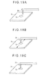
- a tip end of a stylus 24 on the microlens molding surface 72 is required to position a tip end of a stylus 24 on the microlens molding surface 72 while visually checking a relative position between the tip end of the stylus 24 and the microlens molding surface 72 (see Fig. 19A ), to move a stage on which the microlens array mold 71 (the object) is mounted (see Fig. 19B ), to detect the vertex of the microlens molding surface 72 (see Fig. 19C ), and to relatively move the stylus 24 so as to trace the center line of the microlens molding surface 72.
- a setting time of the stylus is extremely longer than a measuring time (for instance, the measuring time is approximately 10 seconds and the setting time is approximately 120 seconds).
- An object of the invention is to provide a surface texture measuring machine for shortening a setting time of a stylus and a surface texture measuring method for the same.
- Another object of the invention is to provide a surface texture measuring machine for shortening a time in a preliminary measurement and not damaging an object in the preliminary measurement.
- an operator operates the relative movement mechanism and acquires the position data of at least three points on the circular contour of the circular concave portion or the circular convex portion of the object by using the image probe.
- the controller approximates the inputted position data to a circle to obtain the center position of the circle (a center position calculating unit) and operates the relative movement mechanism to position the stylus of the contact-type detector at the center position (a stylus setting unit).
- the stylus of the contact-type detector can be automatically set at the center position of the circular concave portion or the circular convex portion of the object.
- the operator does not have to position the tip end of the stylus on a microlens molding surface while visually checking and adjusting the position of the tip end of the stylus relative to the microlens molding surface as in a typical apparatus, thereby shortening the setting time of the stylus.
- one of the stylus of the contact-type detector and the image probe is located at an offset position not to interfere with the other of the stylus of the contact-type detector and the image probe which is to be measured, the surface texture measuring machine further including an offset amount storage unit that stores an offset amount of a tip end of the stylus of the contact-type detector and the image probe, and when the center position is obtained by the center position calculating unit, the stylus setting unit operates the relative movement mechanism to position the image probe at the center position and then operates the relative movement mechanism by the offset amount stored in the offset amount storage unit to position the stylus of the contact-type detector at the center position.
- the offset amounts between the tip end of the stylus of the contact-type detector and the image probe are stored in the offset amount storage unit. Accordingly, by moving the relative movement mechanism, by the offset amounts stored in the offset amount storage unit after calculating the center position of the circular concave portion or the circular convex portion and positioning the image probe at the center position by operating the relative movement mechanism, the stylus of the contact-type detector can be automatically positioned at the center position.
- the stylus of the contact-type detector can be automatically positioned at the center position of the circular concave portion or the circular convex portion with a simple operation and processing.
- a surface texture measuring method for measuring a surface texture of an object having a circular concave portion or a circular convex portion by using a surface texture measuring machine including: a stage on which the object is mounted; a contact-type detector having a stylus that is brought into contact with a surface of the object; an image probe that captures an image of the surface of the object; a relative movement mechanism that relatively moves the stage against the contact-type detector and the image probe and/or relatively moves the contact-type detector and the image probe against the stage; and a controller that controls a drive of the relative movement mechanism and executes processing on measurement data obtained by the contact-type detector and image data captured the image probe, the surface texture measuring method including: acquiring position data of at least three points on a circular contour of the circular concave portion or the circular convex portion of the object by the image probe by operating the relative movement mechanism; approximating the position data to a circle to obtain a center position of the circle; operating the relative movement mechanism to position the stylus of the contact
- the relative movement mechanism is operated and the position data of the at least three points on the circular contour of the circular concave portion or the circular convex portion of the object are acquired by the image probe.
- the position data acquired in the contour data acquisition step are approximated to the circle to calculate the center position of the circle.
- the relative movement mechanism is operated and the stylus of the contact-type detector is positioned at the center position obtained at the circle approximation step.
- the measuring step the surface texture of the circular concave portion or the circular convex portion is measured while the stylus of the contact-type detector and the object are relatively moved by operating the relative movement mechanism.
- the stylus of the contact-type detector can be set at the center position of the circular concave portion or the circular convex portion.
- the operator does not have to set the tip end of the stylus at the measurement starting position on the object while visually checking and adjusting the position of the tip end of the stylus relative to the measurement area on the object as in a typical apparatus, thereby shortening the setting time of the stylus.
- a surface texture measuring machine for measuring a surface texture of an object after adjusting an attitude of the object in parallel to or perpendicular to a predetermined measurement axis includes: a stage provided with a turntable on which the object is mounted, the turntable rotating the object within a predetermined plane; a contact-type detector having a stylus that is brought into contact with a surface of the object; an image probe that captures an image of the surface of the object; a relative movement mechanism that enable relative movement between the turntable and the contact-type detector; and a controller that controls the relative movement mechanism and the turntable, the controller including: an image probe control unit that captures the image of the object by the image probe; an inclination calculating unit that calculates an inclination angle of the object relative to the measurement axis based on the image of the object capture by the image probe control unit; and an attitude adjusting unit that rotates the turntable based on the inclination angle calculated by the inclination calculating unit and adjusts the attitude of the object in
- the image probe captures the image of the object to calculate the inclination angle of the object relative to the measurement axis. Accordingly, the number of the steps in the preliminary measurement can be decreased, thereby shortening the time for the preliminary measurement. Moreover, since the measurement is carried out by the image probe, the measurement time can be shortened as compared with the measurement by the stylus. Consequently, the time for the preliminary measurement can be considerably shortened.
- the preliminary measurement is a noncontact measurement by the image probe, the object is not damaged.
- a surface texture measuring machine for measuring a surface texture of an object after adjusting an attitude of the object in parallel to or perpendicular to a predetermined measurement axis includes: a stage provided with a leveling table on which the object is mounted, the leveling table inclining the object relative to a reference plane perpendicular to a displacing direction of the stylus; a contact-type detector having a stylus that is brought into contact with a to-be-measured surface of the object; an image probe that captures an image of the surface af the object; a relative movement mechanism that enable relative movement between the leveling table and the contact-type detector; and a controller that controls the relative movement mechanism and the leveling table, the controller including: a focusing unit that moves the image probe in a direction perpendicular to the reference plane at a plurality of points of the to-be-measured surface by the relative movement mechanism and determines a focal point of the image probe at each of the points; an inclination calculating unit that
- the preliminary measurement is a noncontact measurement by the image probe, the object is not damaged.
- the surface texture measuring machine includes: a movement course calculating unit that, when a measurement starting position on the object is designated based on the image of the object captured by the image probe, calculates and stores a movement course of the relative movement mechanism so that the stylus of the contact-type detector is brought into contact with the measurement starting position on the object; and a stylus setting unit that operates the relative movement mechanism to follow the movement course calculated by the movement course calculating unit.
- the movement course calculating unit calculates and stores the movement course of the relative movement mechanism so that the stylus of the contact-type detector is brought into contact with the measurement starting position on the object.
- the relative movement mechanism is moved in accordance with the movement course calculated by the movement course calculating unit. In other words, the relative movement mechanism is moved in accordance with the stored movement course, thereby bringing the stylus of the contact-type detector into contact with the measurement starting position on the object.
- the stylus of the contact-type can be automatically set at the measurement starting position on the object.
- the operator does not have to set the tip end of the stylus at the measurement starting position on the object while visually checking and adjusting the position of the tip end of the stylus relative to the measurement starting position on the object as in a typical apparatus. Therefore, the stylus can be prevented from interfering with the object while reducing the burden on the operator.
- the image probe preferably includes a probe body and a probe head that is supported at a tip end of the probe body and is capable of capturing the image of the object, the probe head being attached to the probe body in a manner to be rotatable around an axis perpendicular to a direction of the relative movement of the contact-type detector and the stage and a displacing direction of the stylus when the stylus is in contact with the object.
- the image probe includes the probe body and the probe head that is supported at the tip end of the probe body and is capable of capturing the image of the object.
- the probe head is attached to the probe body in a manner to be rotatable around the axis perpendicular to the direction in which the contact-type detector and the stage are relatively moved (i.e., a trace direction) and the displacing direction of the stylus when the stylus is in contact with the object. Accordingly, by rotating the probe head around the axis, the probe head can be oriented in the displacing direction of the stylus and a direction perpendicular to the displacing direction.
- an image of the object from a horizontal surface can be captured.
- an image of the object from a vertical surface can be captured. Accordingly, even at a measurement of an inner surface texture of a hole formed on the vertical surface, by capturing the image of the vertical surface of the object by using the image probe, the stylus can be accurately positioned inside the hole formed on the vertical surface. Therefore, the stylus can be prevented from interfering with the object while reducing the burden on the operator.
- a surface texture measuring machine includes: a mount stand 1; a base 2 being fixed on an upper surface of the mount stand 1; a stage 10 being mounted on the base 2, the stage 10 having an upper surface on which an object is mounted; a contact-type detector 20 being provided with a stylus 24 that is brought into contact with a surface of the object; an image probe 30 capturing an image of the surface of the object; a relative movement mechanism 40 that relatively moves the stage 10 against the contact-type detector 20 and the image probe 30 and moves the contact-type detector 20 and the image probe 30 against the stage 10; and a controller 50.
- the relative movement mechanism 40 includes: a Y-axis driving mechanism 41 as a first movement mechanism being located between the base 2 and the stage 10 to move the stage 10 in a horizontal direction (Y-axis direction); a column 42 that stands upright on an upper surface of the base 2; a Z-slider 43 as a lifting member being provided to the column 42 movably in a vertical direction (Z-axis direction); a Z-axis driving mechanism 44 as a second movement mechanism that drives the Z-slider 43 to move in the vertical direction; a rotary plate 46 being provided to the Z-slider 43 via a rotation mechanism 45 (see Fig.
- an X-slider 47 as a slide member being provided to the rotary plate 46 so as to be movable in a direction (X-axis direction) perpendicular to the moving direction of the stage 10 (Y-axis direction) and the lifting direction of the Z-slider 43 (Z-axis direction); and an X-axis driving mechanism 48 as a third movement mechanism that drives the X-slider 47 to move in the X-axis direction.
- the contact-type detector 20 and the image probe 30 are attached to the X-slider 47. Therefore, the relative movement mechanism 40 is provided by a three-dimensional movement mechanism that includes the Y-axis driving mechanism 41 that moves the stage 10 in the Y-axis direction, the Z-axis driving mechanism 44 that moves the contact-type detector 20 and the image probe 30 in the Z-axis direction, and the X-axis driving mechanism 48 that moves the contact-type detector 20 and the image probe 30 in the X-axis direction.
- Each of the Y-axis driving mechanism 41 and the Z-axis driving mechanism 44 is provided by, for instance, a feed screw mechanism (not shown) that includes a ball screw shaft and a nut member screwed to the ball screw shaft.
- the X-axis driving mechanism 48 includes a driving mechanism body 48A fixed to the rotary plate 46, a guide rail 48B provided to the driving mechanism body 48A in parallel to the X-axis direction to movably support the X-slider 47, a driving source (not shown) that drives the X-slider 47 to reciprocate along the guide rail 48B, and the like.
- the contact-type detector 20 includes a detector body 21 being hung and supported on the X-slider 47, and a contact-type probe 22 being supported on the detector body 21 in parallel to the X-axis direction.
- the contact-type probe 22 includes a probe body 23, an arm 25 being swingably supported on the probe body 23 and being provided with the stylus 24 at a tip end thereof, and a detecting portion 26 that detects a swing amount of the arm 25.
- the image probe 30 includes a cylindrical probe body 32 being integrally connected to the X-slider 47 via a connecting member 3 along with the contact-type detector 20, and a probe head 33 being downwardly supported on a tip end of the probe body 32.
- the probe head 33 includes an objective lens 35, an LED 36 as a light source being located on an outer periphery of the objective lens 35, a CCD sensor 37 that receives reflected light from the object that has passed through the objective lens 35 to capture an image of the object, and a cover 38 that covers the LED 36 and the surroundings thereof.
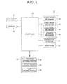
- the controller 50 is connected to an input device 51, a display 52 and a storage 53 in addition to the relative movement mechanism 40, the contact-type detector 20 and the image probe 30.
- the input device 51 is provided with, for instance, a portable keyboard, a joystick or the like and is used not only to input various kinds of operation commands and data but also to designate a position at which the stylus 24 is to be set (measurement starting position) in accordance with the image captured by the image probe 30.
- the display 52 shows not only the image captured by the image probe 30 but also profile and/or roughness data obtained by the contact-type detector 20.
- the storage 53 includes a program storing portion 54 that stores a measurement program and the like, an offset amount storing portion 55 as an offset amount storage unit that stores the offset amounts OFx, OFy and OFz between the stylus 24 of the contact-type detector 20 and the image probe 30, a data storing portion 56 that stores image data and measurement data obtained from measurement, and the like.
- the controller 50 includes: a center position calculating unit that, when position data of at least three points of a circular contour of a circular concave portion or circular convex portion of the object are entered by the image probe 30 in accordance with the measurement program stored in the program storing portion 54, approximates the entered position data to a circle to obtain a center position of the circle; a stylus setting unit that, when the center position is obtained by the center position calculating unit, operates the relative movement mechanism 40 to position the stylus 24 of the contact-type detector 20 at the center position; and a measurement performing unit that operates the relative movement mechanism 40 to enable relative movement between the contact-type detector 20 and the object while the stylus 24 of the contact-type detector 20 is in contact with the object, thereby measuring the surface texture of the object.
- the stylus setting unit When the center position is obtained by the center position calculating unit, the stylus setting unit operates the relative movement mechanism 40 to position the image probe 30 at the center position and operates the relative movement mechanism 40 by offset amounts of OFx, OFy and OFz stored in an offset amount storing portion 55 to position the stylus 24 of the contact-type detector 20 at the center position.
- the controller 50 further includes an edge detection function for detecting the edge of the object in the image of the object captured by the image probe 30, and an auto-focusing function for displacing the objective lens 35 in a heightwise direction of the object (Z-axis direction) so that the focal point of the objective lens is set at the surface of the object defined in the heightwise direction to detect a heightwise position of the object depending on the displacement amount of the objective lens 35.
- the edge detection function may be based on any know principle of detection but may use, for instance, a technique in which an average intensity (light intensity) in a direction perpendicular to the detection direction of the image probe 30 is obtained to detect a position at which the average intensity becomes equal to or below a preset threshold as the edge.
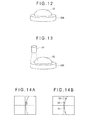
- An object 60A includes a circular concave portion 61 at a center thereof.
- the circular concave portion 61 has a circular contour and a spherical and concave interior.
- the circular concave portion 61 is exemplified by a concave microlens molding surface formed on a microlens array mold, but not limited to this.
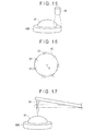
- the controller 50 approximates the entered position data to the circle 63 to obtain the center position C of the circle 63, and then operates the relative movement mechanism 40 to position the stylus 24 of the contact-type detector 20 at the center position C.
- the stylus 24 of the contact-type detector 20 can be automatically set at the center position C of the circular concave portion 61 of the object 60A.
- the operator does not have to position the tip end of the stylus at the circular concave portion while visually checking and adjusting the position of the tip end of the stylus relative to the circular concave portion as in a typical apparatus, thereby shortening the setting time of the stylus.
- the stylus 24 of the contact-type detector 20 and the image probe 30 are offset from each other in the Z-axis direction and the Y-axis direction respectively by the offset amounts OFz and OFy.
- the stylus 24 and the image probe 30 can be prevented from being interfered with each other without providing a mechanism for evacuating one of the stylus 24 and the image probe 30 that is not used for the measurement.
- the offset amounts OFx, OFy and OFz between the tip end of the stylus 24 of the contact-type detector 20 and the image probe 30 are stored in the offset amount storing portion 55. Accordingly, by calculating the center position C of the circular concave portion 61, operating the relative movement mechanism 40 to position the image probe 30 at the center position C and operating the relative movement mechanism 40 by the offset amounts OFx, OFy and OFz stored in the offset amount storing portion 55, the stylus 24 of the contact-type detector 20 can be automatically positioned at the center position C.
- the stylus 24 of the contact-type detector 20 can be automatically positioned at the center position C of the circular concave portion 61 with a simple operation and processing.
- only the image probe 30 can be used for the measurement.
- a width of a line, a diameter of a hole, or the like can be measured by using an image captured by the image probe 30, a dimension in an optical-axial direction of the objective lens 35 (level difference height) or the like can be measured by using the auto-focusing function of the image probe 30.
- the relative movement mechanism 40 includes the Y-axis driving mechanism 41 that moves the stage 10 on which the object is mounted in the Y-axis direction, and the X-axis driving mechanism 48 and the Z-axis driving mechanism 44 that respectively move the contact-type detector 20 and the image probe 30 in the X-axis direction and the Z-axis direction.
- the relative movement mechanism 40 enables the object and the contact-type detector 20 and the image probe 30 to move in the three dimensional directions, i.e., the X-axis direction, the Y-axis direction and the Z-axis direction that are set perpendicular to one another.
- the profile and surface roughness of the object can be measured irrespective of an orientation and attitude of a measurement portion of the object.
- Both the contact-type detector 20 and the image probe 30 are attached to the X-slider 47 while being offset from each other.
- a simple and low-cost structure as compared with a device in which a mechanism is provided for separately moving the contact-type detector 20 and the image probe 30.
- the image probe 30 includes the objective lens 35, the LED 36 as a light source being located on the outer periphery of the objective lens 35, and the CCD sensor 37 that receives reflected light from the object that has passed through the objective lens 35.
- the CCD sensor 37 can highly accurately obtain the image of the surface of the object through the objective lens 35.
- the LED 36 is located around the objective lens 35, the image probe 30 can be downsized as compared with a case where a lighting device is separately provided.
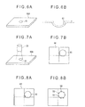
- the object to be measured is not limited to the object shown in Figs. 6A and 6B .
- the object may be an object 60B including a circular convex portion 62 at a center thereof.
- the circular convex portion 62 has a circular contour and a spherical and convex interior.
- a surface texture of the circular convex portion 62 of the object 60B is measured as shown in Figs. 13 to 17 .
- the accuracy of this measurement is expected to be improved by calculating an inclination (an inclination relative to the horizon) of the object 60B based on the automatically-focused data in the heightwise direction of the object 60B (Z-axis direction) and changing the attitude of the object 60B, when the automatic focus and the edge detection are performed in three other positions where the circular convex portion 62 of the object 60B is located within the visual field of the image probe 30.
- the attitude of the object 60B can be changed by inserting an inclined table between the stage 10 and the object 60B and moving the inclined table.
- the contact-type detector 20 includes the arm 25 being provided with the stylus 24 at the tip end thereof and the detecting portion 26 that detects the swing amount of the arm 25, the contact-type detector 20 may have any other arrangement as long as the surface profile and roughness of an object can be measured while the stylus 24 is in contact with the object.
- the image probe 30 includes the probe head 33 being provided with the objective lens 35, the LED 36 as a light source being located on the outer periphery of the objective lens 35 and the CCD sensor 37 that receives reflected light from the object that has passed through the objective lens 35 to capture the image of the object, the invention is not limited thereto.
- the LED 36 as a light source may be provided separately from the image probe.
- the objective lens 35 may be replaceable so that the objective lens 35 is replaced with one having a different magnification, so that an appropriate operation can be performed depending on the size of the measurement area on the object.
- the relative movement mechanism 40 enables the stage 10 to move in the Y-axis direction and the contact-type detector 20 and the image probe 30 to move in the X-axis direction and the Z-axis direction
- the invention is not limited thereto.
- either one of the stage 10 and the contact-type detector 20 and the image probe 30 may be movable.
- the contact-type detector 20 and the image probe 30 may be associated with their respective relative movement mechanisms so that the contact-type detector 20 and the image probe 30 are independently moved.
- a surface texture measuring machine can adjust the attitude of the object in parallel to or perpendicular to a predetermined measurement axis. As shown in Figs. 20 and 21 , a turntable 10A is added to the surface texture measuring machine according the first exemplary embodiment.
- the turntable 10A is mounted on the stage 10 and rotated by a command from the controller 50.
- an object W is rotated within a horizontal plane (an XY plane).
- the object W is cylindrical in the second exemplary embodiment.
- the image probe 30 includes a component for positioning the object W at the focal point of the objective lens 35 as needed in addition to the above components.
- the image probe 30 includes a tube lens provided at a dawnstream of an optical path of the objective lens 35, and photodiodes respectively provided on a front side and a rear side of a focal point of the tube lens.
- the image probe 30 is moved by the controller 50 via the relative movement mechanism 40 in a vertical direction relative to the object W so as to equalize the amounts of light received by the respective photodiodes to be positioned where the object W is located at the focal point of the objective lens 35.
- the image probe 30 when the relative position between the image probe 30 and the object W is to be determined by a so-called contrast method, the image probe 30 includes a light source projecting a predetermined pattern onto the object W via a projection plate and an objective lens. The image probe 30 captures the predetermined pattern projected on the object W. In addition, the image probe 30 is moved by the controller 50 via the relative movement mechanism 40 in a vertical direction relative to the object W based on a contrast of the captured pattern image, and is positioned where the object W is located at the focal point of the objective lens 35.
- a measurement value includes a value showing a cylindrical outer circumferential profile, thereby causing an error in a measurement result.
- the controller 50 includes an image probe control unit 50A, an inclination angle calculating unit 50B and an attitude adjusting unit 50C. These units 50A to 50C perform a preliminary measurement in advance of an actual measurement and adjust the attitude of the object W, for instance, in parallel to the measurement axis.
- Fig. 22 is a flow chart for showing the attitude adjustment method.
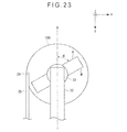
- Fig. 23 is a plan view showing the image probe 30 and the object W.
- the operator controls the relative movement mechanism 40 by operating the input device 51 and moves the image probe 30 above the object W.
- the image probe control unit 50A moves the image probe 30 in a vertical direction (a Z axis direction) by controlling the relative movement mechanism 40 and positions the object W at the focal point of the objective lens 35 to capture an image of the object W by the image probe 30 (an image capture step S1).
- a focusing method of the image probe 30 by the image probe control unit 50A in this step any method such as the pinhole method and the contrast method as described above is applicable as needed.
- the inclination angle calculating unit 50B calculates a generatrix B of the object W from an outer profile of the object W based on the captured image of the object W to calculate an inclination angle ⁇ of the generatrix B relative to the measurement axis A as an inclination angle ⁇ of the object W relative to the measurement axis A (an inclination angle calculation step S2).
- Fig. 24 is a plan view showing an attitude adjustment of the object W by the attitude adjusting unit 50C.
- the attitude adjusting unit 50C rotates the turntable 10A based on the inclination angle ⁇ and adjusts the attitude of the object W in parallel to the measurement axis A (an adjustment step S3). Accordingly, the attitude of the object W is adjusted in parallel to the measurement axis A, thereby carrying out the actual measurement with high accuracy.
- Fig. 25 is a plan view showing the actual measurement by the controller 50.
- the controller 50 controls the relative movement mechanism 40 to move the stylus 24 to the inputted measurement starting position.
- the controller 50 controls the X-axis driving mechanism 48 and moves the stylus 24 from the measurement starting position to an inputted measurement end position along the measurement axis A, thereby measuring the surface texture of the object W along the axial direction.
- the respective units 50A to 50C perform the so-called alignment, by which the attitude of the object W is adjusted in parallel to the measurement axis A.
- the respective units 50A to 50C perform a so-called right angling, by which the attitude of the object W is adjusted perpendicular to the measurement axis A, in the same manner as that in the alignment.
- the right-angling of the object W by the respective units 50A to 50C will be simply described as follows.
- Fig. 26 is a plan view showing the image probe 30 that captures the object W.
- the image probe control unit 50A captures the image of the object W by the image probe 30 (the image capture step S1).
- the inclination angle calculating unit 50B calculates the inclination angle ⁇ of the object W relative to the measurement axis A based on the captured image of the object W (the inclination angle calculation step S2).
- Fig. 27 is a plan view showing an attitude adjustment of the object W by the attitude adjusting unit 50C.
- the attitude adjusting unit 50C rotates the turntable 10A based on the inclination angle ⁇ and adjusts the attitude of the object W perpendicular to the measurement axis A (the adjustment step S3). Thus, the right-angling is completed. Subsequently, the controller 50 moves the stylus 24 along the measurement axis A, thereby measuring the surface texture of the object W along a direction perpendicular to the axial direction.
- the image probe 30 captures the image of the object W to calculate the inclination angle ⁇ of the object W relative to the measurement axis A. Accordingly, the number of the steps in the preliminary measurement can be decreased, thereby shortening the time for the preliminary measurement. Moreover, since the measurement is carried out by the image probe 30, the measurement time can be shortened as compared with the measurement by the stylus 24. Consequently, the time for the preliminary measurement can be considerably shortened.
- the preliminary measurement is a noncontact measurement by the image probe 30, the object W is not damaged.
- a table mounted on the stage is not limited to the table shown in Fig. 20 .
- the surface texture measuring mechanism as shown in Fig. 28 may be provided with a leveling table 10B in place of the turntable 10A.
- a rectangular parallelepiped object W is mounted on the leveling table 10B shown in Fig. 28 .
- the leveling table 10B inclines the object W relative to a horizontal plane which is a reference plane perpendicular to a displacing direction (vertical direction) of the stylus 24.
- the respective units 50A to 50C of the controller 50 shown in Fig. 29 perform a so-called leveling by which the attitude of the object W is adjusted so as to horizontalize a to-be-measured surface S.
- Fig. 31A shows the leveling table 10B that is horizontally situated.
- Fig. 31B shows the leveling table 10B inclined at an angle where the to-be-measured surface S is horizontal.
- the operator controls the relative movement mechanism 40 via the input device 51 and moves the image probe 30 above points (for instance, three points) of the to-be-measured surface S.
- the image probe control unit 50A moves the image probe 30 in a vertical direction by the relative movement mechanism 40 so that the each of the points is positioned at the focal point of the objective lens 35 (a focusing step SA1).
- a height of the image probe 30 at the each of the points is detected by a sensor (not shown) provided in the Z-axis driving mechanism 44.
- the image probe control unit 50A is a focusing unit.
- the inclination angle calculating unit 50B calculates the inclination angle ⁇ of the to-be-measured surface S relative to the horizontal plane based on the height of the image probe 30 at the each of the points of the to-be-measured surface S (an inclination angle calculation step SA2).
- the attitude adjusting unit 50C rotates the leveling table 10B based on the inclination angle ⁇ and adjusts the attitude of the object W so that the to-be-measured surface S thereof is horizontal (the adjustment step SA3).
- the controller 50 moves the stylus 24 along the measurement axis A, thereby measuring the surface texture of the object W.
- the leveling table 10B is schematically shown in Figs. 28 and 31 and is rotatable in a counterclockwise direction.
- a profile of the object of which attitude is adjustable is not limited to the above-mentioned profile.
- an attitude of the object having any profile is adjustable.
- the surface texture measuring machine according to the exemplary embodiment may include a table functioning as the turntable and the leveling table, by which the surface texture measuring machine according to the exemplary embodiment adjusts the attitude of the object in parallel to the measurement axis and adjusts the to-be-measured surface so that the to-be-measured surface is horizontal.
- a surface texture measuring machine can automatically set a stylus of a contact-type detector at a measurement starting position of an object based on an image of the object captured by an image probe.
- the image probe 30 and the controller 50 are different in a structure from those of the surface texture measuring machine according the first exemplary embodiment.
- the image probe 30 of the third exemplary embodiment includes: a cylindrical probe body 32 that is integrally connected to the X-slider 47 via the connecting member 31 along with the contact-type detector 20; and the probe head 33 that is rotatably supported around an axis (Y-axis) perpendicular to a direction (Y-axis direction) in which the contact-type detector 20 and the stage 10 relatively move and the displacing direction of the stylus 24 (Z-axis direction: vertical direction) while the stylus 24 is in contact with the object, the probe head 33 being provided at a tip end of the probe body 32; and a head turning mechanism 34 such as a motor for rotating the probe head 33.
- the controller 50 includes: a movement course calculating unit that, when the measurement starting position is designated based on the image of the object captured by the image probe 30 in accordance with the measurement program stored in the program storing portion 54, calculates and stores the movement course of the relative movement mechanism 40 so that the stylus 24 of the contact-type detector 20 is brought into contact with the measurement starting position on the object; a stylus setting unit that drives the relative movement mechanism 40 along the movement course calculated by the movement course calculating unit; and a measurement performing unit that operates the relative movement mechanism 40 so that the contact-type detector 20 is moved relative to the object while the stylus 24 of the contact-type detector 20 is in contact with the object, thereby measuring the surface profile of the object.
- the controller 50 further includes an edge detection function for detecting the edge af the object in the image of the object captured by the image probe 30, and an auto-focusing function for displacing the objective lens 35 in the heightwise direction of the object (Z-axis direction) so that the focal point of the objective lens is set at the surface of the object defined in the heightwise direction to detect the heightwise position of the object depending on the displacement amounts of the objective lens 35.
- the edge detection function may be based on any known principle of detection but may use, for instance, a technique in which an average intensity (light intensity) in a direction perpendicular to the detection direction of the image probe 30 is obtained to detect a position at which the average intensity becomes equal to or below a preset threshold as the edge.
- the object 80 includes: a horizontal wall 81; a vertical wall 82 perpendicularly erected at one end of the horizontal wall 81; and an inclined wall 83 formed in an inclined manner between the horizontal wall 81 and the vertical wall 82.
- Four holes 82A to 82D are formed on both ends of the vertical wall 82 interposing the inclined wall 83.
- Two holes 81A and 81B are formed on both ends of the horizontal wall 81.
- a hole 83A is formed at a center of the inclined wall 83 in a manner perpendicular to the inclined wall 83.
- the probe head 33 of the image probe 30 is held in a horizontal attitude by a command of the input device 51.
- the image probe 30 captures an image of the vertical wall 82 of the object 80.
- the image data of the vertical wall 82 of the object 80 is stored in the data storing portion 56 and then is displayed on the display 52.
- a measurement starting position (a position at which the stylus 24 of the contact-type defector 20 is first brought into contact), for instance, a lower inner-circumferential surface of the hole 82A
- the controller 50 calculates the movement course of the relative movement mechanism 40 in consideration of the offset amounts OFx, OFy and OFz stored in the offset amount storing portion 55 so that the stylus 24 of the contact-type detector 20 is brought into contact with the lower inner-circumferential surface of the hole 82A on the object 80.
- the calculated movement course is stored in the program storing portion 54.
- the controller 50 operates the relative movement mechanism 40 in accordance with the movement course stored in the program storing portion 54.
- the controller 50 operates the relative movement mechanism 40 so that the stylus 24 of the contact-type detector 20 is brought into contact with the designated position (the lower inner-circumferential surface of the hole 82A).
- the controller 50 When the stylus 24 of the contact-type detector 20 is set at the lower inner-circumferential surface of the hole 82A, the controller 50 operates the X-axis driving mechanism 48. Then, the stylus 24 of the contact-type detector 20 is moved from the designated position in the X-axis direction. With this movement, the stylus 24 is vertically displaced in accordance with the surface roughness of the object 80 in contact with the stylus 24 and the displacement amount of the stylus 24 is detected by the detecting portion 26. Consequently, the surface roughness of the hole 82A of the object 80 is measured according to the displacement amount and the movement amount of the stylus 24.
- the probe head 33 of the image probe 30 is rotated by a command of the input device 51 and is held in an attitude opposing the inclined wall 83.
- the image probe 30 captures an image of the inclined wall 83 of the object 80.
- the image data of the inclined wall 83 of the object 80 is stored in the data storing portion 56 and then is displayed on the display 52.
- the controller 50 calculates the movement course of the relative movement mechanism 40 in consideration of the offset amounts OFz and OFy stored in the offset amount storing portion 55 so that the stylus 24 of the contact-type detector 20 is brought into contact with the lower inner-circumferential surface of the hole 83A on the object 80.
- the calculated movement course is stored in the program storing portion 54.
- the controller 50 operates the relative movement mechanism 40 in accordance with the movement course stored in the program storing portion 54.
- the controller 50 inclines the X-axis driving mechanism 48 by rotating the rotation mechanism 45, thereby aligning the inclination of the hole 83A with the moving direction of X-axis driving mechanism 48.
- the controller 50 operates the relative movement mechanism 40 so that the stylus 24 of the contact-type detector 20 is brought into contact with the designated lower inner-circumferential surface of the hole 83A.
- the controller 50 When the stylus 24 of the contact-type detector 20 is set at the designated position, the controller 50 operates the X-axis driving mechanism 48. Then, the stylus 24 of the contact-type detector 20 is moved from the designated position in an axial direction of the hole 83A. With this movement, the stylus 24 is vertically displaced in accordance with the surface roughness of the object 80 in contact with the stylus 24 and the displacement amount of the stylus 24 is detected by the detecting portion 26. Consequently, the surface roughness of the hole 83A of the object 80 is measured according to the displacement amount and the movement amount of the stylus 24.
- the probe head 33 of the image probe 30 is rotated by a command of the input device 51 and is held in a downward attitude.
- the image probe 30 captures an image of the horizontal wall 81 of the object 80
- the image data of the horizontal wall 81 of the object 80 is stored in the data storing portion 56 and then is displayed on the display 52.
- the controller 50 executes processing on the image of the horizontal wall 81 of the object 80 stored in the data storing portion 56 to measure profiles and sizes of the holes 81A and 81B.
- a surface texture measuring machine includes the contact-type detector 20 provided with the stylus 24 that is brought into contact with a surface of an object and the image probe 30 that captures an image of the surface of the object.
- the stylus 24 of the contact-type detector 20 can be automatically brought into contact with a measurement position on the object based on the captured image of the object. Accordingly, the operator is not required to set a tip end of the stylus at a measurement starting position of the object while visually checking and adjusting the position of the tip end of the stylus relative to the measurement starting position as in a typical apparatus. Therefore, the stylus can be prevented from interfering with the object while reducing the burden on the operator.
- the offset amounts OFz and OFy between the tip end of the stylus 24 of the contact-type detector 20 and the image probe 30 are stored in the offset amount storing portion 55. These offset amounts stored in the offset amount storing portion 55 are taken into consideration in calculating the movement course of the relative movement mechanism 40 so that the stylus 24 of the contact-type detector 20 is brought into contact with the measurement starting position on the object. Since the relative movement mechanism 40 is operated in accordance with this measurement course, the stylus 24 of the contact-type detector 20 can be accurately brought into contact with the measurement starting position on the object.
- the image probe 30 includes: the cylindrical probe body 32 that is integrally connected to the X-slider 47 along with the contact-type detector 20; the probe head 33 that is rotatably supported around an axis in parallel to the Y-axis, the probe head 33 being provided at the tip end of the probe body 32; and the head turning mechanism 34 such as a motor for rotating the probe head 33. Accordingly, the downward attitude of the probe head 33 can be changed to the horizontal attitude thereof by the head turning mechanism 34.
- the image of the vertical surface or any inclined surface as well as the horizontal surface of the object can be captured so that a profile of a hole or a protrusion provided on such surfaces can be measured by the contact-type detector 20.
Landscapes
- Physics & Mathematics (AREA)
- General Physics & Mathematics (AREA)
- A Measuring Device Byusing Mechanical Method (AREA)
- Length Measuring Devices By Optical Means (AREA)
Abstract
Description
- The present invention relates to a surface texture measuring machine for measuring surface profiles, surface roughness and the like of an object to be measured and a surface texture measuring method. Specifically, the present invention relates to a surface texture measuring machine including a contact-type detector provided with a stylus and an image probe, and a surface texture measuring method.
- There has been known a surface texture measuring machine in which a stylus is moved along a surface of an object while being in contact with the surface of the object. A displacement of the stylus due to a surface profile or surface roughness of the object is detected, thereby measuring the surface profile, surface roughness and the like of the object based on the displacement of the stylus (see, for instance, Patent Literature:
JP-A-05-087562 - In such a typical surface texture measuring machine, in order to measure the surface profile, surface roughness and the like of the object, while visually checking and adjusting a relative position between a tip end of a stylus and a measurement area on the object, an operator sets the tip end of the stylus at a measurement starting position on the object and then moves the stylus along the surface of the object. A surface texture such as the surface profile and the surface roughness of the object is measured based on a vertical displacement of the stylus due to the surface profile, surface roughness and the like of the object.
- Moreover, in the surface texture measuring machine, when an attitude of the object is inclined relative to a measurement axis in measuring a surface of the object, a measurement result may have an error. For instance, when an attitude of a cylinder is inclined relative to a measurement axis in measuring an axial texture of a surface of the cylinder, a stylus is displaced in an outer circumferential direction of the cylinder as well as in an axial direction of the cylinder while the stylus is moved along the measurement axis. For this reason, a measurement value includes a value showing an outer circumferential texture of the cylinder as well as a value showing an axial concavity and convexity of the surface of the cylinder, so that the measurement result has an error. Moreover, in the surface texture measuring machine, when a to-be-measured surface is inclined relative to a horizontal plane, the measurement result may also have an error.
- Accordingly, there has been developed a surface texture measuring machine that performs a preliminary measurement of an object with a stylus before an actual measurement and adjusts an attitude of the object, for instance, in parallel to a measurement axis based on a result of the preliminary measurement (for instance, Patent Literature 2:
JP-A-2000-266534 Patent Literature 2 includes a turntable that rotates the object on a horizontal plane. The surface texture measuring machine rotates the turntable based on the result of the preliminary measurement performed with the stylus and adjusts the attitude of the object in parallel to the measurement axis (so-called alignment). - Also, the surface texture measuring machine of
Patent Literature 2 includes a leveling table that inclines the object relative to the horizontal plane. The surface texture measuring machine inclines the leveling table based on the result of the preliminary measurement performed with the stylus and adjusts the attitude of the object so that the to-be-measured surface thereof is horizontal (so-called leveling). - Due to a recent tendency for measuring minute and thin objects, objects or measuring spots are downsized. Accordingly, the above setting operation of a stylus, which is quite complicated and requires a long time, places a large burden on the operator.
- In addition, some types of objects may interfere with (collide with) a stylus to damage the stylus or the objects.
- Particularly, as shown in
Figs. 18A to 18C , in measuring a radius or diameter of each of a plurality ofmicrolens molding surfaces 72 having convexity (or concavity) of 1 mm or less diameter that are formed on amicrolens array mold 71, the stylus must correctly trace a center line where vertexes (peak or bottom points) of themicrolens molding surfaces 72 are located in order to obtain a correct measurement result. - In order to measure such an object, as shown in
Figs. 19A to 19C , in a typical measurement, the operator is required to position a tip end of astylus 24 on themicrolens molding surface 72 while visually checking a relative position between the tip end of thestylus 24 and the microlens molding surface 72 (seeFig. 19A ), to move a stage on which the microlens array mold 71 (the object) is mounted (seeFig. 19B ), to detect the vertex of the microlens molding surface 72 (seeFig. 19C ), and to relatively move thestylus 24 so as to trace the center line of themicrolens molding surface 72. - For this reason, in a typical operation, a setting time of the stylus is extremely longer than a measuring time (for instance, the measuring time is approximately 10 seconds and the setting time is approximately 120 seconds).
- Moreover, in the surface texture measuring machine of
Patent Literature 2, it takes extremely long time for the preliminary measurement because the preliminary measurement requires many steps and uses the stylus for measuring the surface of the object. Further, the object may be damaged by the stylus. - An object of the invention is to provide a surface texture measuring machine for shortening a setting time of a stylus and a surface texture measuring method for the same.
- Another object of the invention is to provide a surface texture measuring machine for shortening a time in a preliminary measurement and not damaging an object in the preliminary measurement.
- According to an aspect of the invention, a surface texture measuring machine for measuring a surface texture of an object includes: a stage on which an object is mounted; a contact-type detector having a stylus that is brought into contact with a surface of the object; an image probe that captures an image of the surface of the object; a relative movement mechanism that relatively moves the stage against the contact-type detector and the image probe and/or relatively moves the contact-type detector and the image probe against the stage; and a controller that controls a drive of the relative movement mechanism and executes processing on measurement data obtained by the contact-type detector and image data captured by the image probe, in which the controller includes: a center position calculating unit that, when the image probe enters position data of at least three points on a circular contour of a circular concave portion or a circular convex portion of the object, approximates the entered position data to a circle to obtain a center position of the circle; and a stylus setting unit that, when the center position calculating unit obtains the center position, operates the relative movement mechanism to position a stylus of the contact-type detector at the center position.
- With this arrangement, firstly, an operator operates the relative movement mechanism and acquires the position data of at least three points on the circular contour of the circular concave portion or the circular convex portion of the object by using the image probe.
- Then, the controller approximates the inputted position data to a circle to obtain the center position of the circle (a center position calculating unit) and operates the relative movement mechanism to position the stylus of the contact-type detector at the center position (a stylus setting unit).
- Accordingly, the stylus of the contact-type detector can be automatically set at the center position of the circular concave portion or the circular convex portion of the object. In other words, the operator does not have to position the tip end of the stylus on a microlens molding surface while visually checking and adjusting the position of the tip end of the stylus relative to the microlens molding surface as in a typical apparatus, thereby shortening the setting time of the stylus.
- In the surface texture measuring machine according to the aspect of the invention, one of the stylus of the contact-type detector and the image probe is located at an offset position not to interfere with the other of the stylus of the contact-type detector and the image probe which is to be measured, the surface texture measuring machine further including an offset amount storage unit that stores an offset amount of a tip end of the stylus of the contact-type detector and the image probe, and when the center position is obtained by the center position calculating unit, the stylus setting unit operates the relative movement mechanism to position the image probe at the center position and then operates the relative movement mechanism by the offset amount stored in the offset amount storage unit to position the stylus of the contact-type detector at the center position.
- With this arrangement, since one of the stylus of the contact-type detector and the image probe is located at an offset position not to interfere with the other of the stylus and the image probe that is used for the measurement, the measurement is not affected even without providing a mechanism for evacuating one of the stylus and the image probe that is not used for the measurement.
- Further, the offset amounts between the tip end of the stylus of the contact-type detector and the image probe are stored in the offset amount storage unit. Accordingly, by moving the relative movement mechanism, by the offset amounts stored in the offset amount storage unit after calculating the center position of the circular concave portion or the circular convex portion and positioning the image probe at the center position by operating the relative movement mechanism, the stylus of the contact-type detector can be automatically positioned at the center position.
- Accordingly, by obtaining and storing the accurate offset amounts between the stylus of the contact-type detector and the image probe in advance, the stylus of the contact-type detector can be automatically positioned at the center position of the circular concave portion or the circular convex portion with a simple operation and processing.
- According to another aspect of the invention, a surface texture measuring method for measuring a surface texture of an object having a circular concave portion or a circular convex portion by using a surface texture measuring machine including: a stage on which the object is mounted; a contact-type detector having a stylus that is brought into contact with a surface of the object; an image probe that captures an image of the surface of the object; a relative movement mechanism that relatively moves the stage against the contact-type detector and the image probe and/or relatively moves the contact-type detector and the image probe against the stage; and a controller that controls a drive of the relative movement mechanism and executes processing on measurement data obtained by the contact-type detector and image data captured the image probe, the surface texture measuring method including: acquiring position data of at least three points on a circular contour of the circular concave portion or the circular convex portion of the object by the image probe by operating the relative movement mechanism; approximating the position data to a circle to obtain a center position of the circle; operating the relative movement mechanism to position the stylus of the contact-type detector at the center position; and measuring the surface texture of the circular concave portion or the circular convex portion of the object while relatively moving the stylus of the contact-type detector and the object by operating the relative movement mechanism after the stylus of the contact-type detector is positioned at the center position of the circular concave portion on the circular convex portion of the object.
- With this arrangement, firstly, in the contour data acquisition step, the relative movement mechanism is operated and the position data of the at least three points on the circular contour of the circular concave portion or the circular convex portion of the object are acquired by the image probe. Then, in the circle approximation step, the position data acquired in the contour data acquisition step are approximated to the circle to calculate the center position of the circle.
- Next, in the stylus setting step, the relative movement mechanism is operated and the stylus of the contact-type detector is positioned at the center position obtained at the circle approximation step. In the measuring step, the surface texture of the circular concave portion or the circular convex portion is measured while the stylus of the contact-type detector and the object are relatively moved by operating the relative movement mechanism.
- Thus, since the center position of the circular concave portion or the circular convex portion is known in advance, the stylus of the contact-type detector can be set at the center position of the circular concave portion or the circular convex portion. In other words, the operator does not have to set the tip end of the stylus at the measurement starting position on the object while visually checking and adjusting the position of the tip end of the stylus relative to the measurement area on the object as in a typical apparatus, thereby shortening the setting time of the stylus.
- According to still another aspect of the invention, a surface texture measuring machine for measuring a surface texture of an object after adjusting an attitude of the object in parallel to or perpendicular to a predetermined measurement axis includes: a stage provided with a turntable on which the object is mounted, the turntable rotating the object within a predetermined plane; a contact-type detector having a stylus that is brought into contact with a surface of the object; an image probe that captures an image of the surface of the object; a relative movement mechanism that enable relative movement between the turntable and the contact-type detector; and a controller that controls the relative movement mechanism and the turntable, the controller including: an image probe control unit that captures the image of the object by the image probe; an inclination calculating unit that calculates an inclination angle of the object relative to the measurement axis based on the image of the object capture by the image probe control unit; and an attitude adjusting unit that rotates the turntable based on the inclination angle calculated by the inclination calculating unit and adjusts the attitude of the object in parallel to or perpendicular to the measurement axis.
- With this arrangement, what is carried out in the preliminary measurement is only that the image probe captures the image of the object to calculate the inclination angle of the object relative to the measurement axis. Accordingly, the number of the steps in the preliminary measurement can be decreased, thereby shortening the time for the preliminary measurement. Moreover, since the measurement is carried out by the image probe, the measurement time can be shortened as compared with the measurement by the stylus. Consequently, the time for the preliminary measurement can be considerably shortened.
- Further, since the preliminary measurement is a noncontact measurement by the image probe, the object is not damaged.
- According to further aspect of the invention, a surface texture measuring machine for measuring a surface texture of an object after adjusting an attitude of the object in parallel to or perpendicular to a predetermined measurement axis includes: a stage provided with a leveling table on which the object is mounted, the leveling table inclining the object relative to a reference plane perpendicular to a displacing direction of the stylus; a contact-type detector having a stylus that is brought into contact with a to-be-measured surface of the object; an image probe that captures an image of the surface af the object; a relative movement mechanism that enable relative movement between the leveling table and the contact-type detector; and a controller that controls the relative movement mechanism and the leveling table, the controller including: a focusing unit that moves the image probe in a direction perpendicular to the reference plane at a plurality of points of the to-be-measured surface by the relative movement mechanism and determines a focal point of the image probe at each of the points; an inclination calculating unit that calculates an inclination angel of the to-be-measured surface relative to the reference plane based on a position perpendicular to the reference plane of the image probe at the each of the points; and an attitude adjusting unit that inclines the leveling table based on the inclination angle calculated by the inclination calculating unit and adjusts the attitude of the object so that the to-be-measured surface is in parallel to the reference plane.
- With this arrangement, what is carried out in the preliminary measurement is only that the image probe is moved in a direction perpendicular to the reference plane so that the each of the points on the to-be-measured surface is positioned at the focal point of the image probe and then the inclination angle of the to-be-measured surface relative to the reference plane is calculated based on the position of the image probe at the each of the points in the direction perpendicular to the reference plane. Accordingly, the number of the steps in the preliminary measurement can be decreased, thereby shortening the time for the preliminary measurement. Moreover, since the measurement is carried out by the image probe, the measurement time can be shortened as compared with the measurement by the stylus. Consequently, the time for the preliminary measurement can be considerably shortened.
- Further, since the preliminary measurement is a noncontact measurement by the image probe, the object is not damaged.
- Preferably, the surface texture measuring machine according to the above aspect of the invention includes: a movement course calculating unit that, when a measurement starting position on the object is designated based on the image of the object captured by the image probe, calculates and stores a movement course of the relative movement mechanism so that the stylus of the contact-type detector is brought into contact with the measurement starting position on the object; and a stylus setting unit that operates the relative movement mechanism to follow the movement course calculated by the movement course calculating unit.
- With this arrangement, the image of the object is initially captured by the image probe. Subsequently, when the measurement starting position on the object is designated based on the captured image of the object, the movement course calculating unit calculates and stores the movement course of the relative movement mechanism so that the stylus of the contact-type detector is brought into contact with the measurement starting position on the object. When a measurement is performed later, the relative movement mechanism is moved in accordance with the movement course calculated by the movement course calculating unit. In other words, the relative movement mechanism is moved in accordance with the stored movement course, thereby bringing the stylus of the contact-type detector into contact with the measurement starting position on the object.
- In this manner, the stylus of the contact-type can be automatically set at the measurement starting position on the object. In other words, the operator does not have to set the tip end of the stylus at the measurement starting position on the object while visually checking and adjusting the position of the tip end of the stylus relative to the measurement starting position on the object as in a typical apparatus. Therefore, the stylus can be prevented from interfering with the object while reducing the burden on the operator.
- In the surface texture measuring machine according to the above aspect of the invention, the image probe preferably includes a probe body and a probe head that is supported at a tip end of the probe body and is capable of capturing the image of the object, the probe head being attached to the probe body in a manner to be rotatable around an axis perpendicular to a direction of the relative movement of the contact-type detector and the stage and a displacing direction of the stylus when the stylus is in contact with the object.
- With this arrangement, particularly, the image probe includes the probe body and the probe head that is supported at the tip end of the probe body and is capable of capturing the image of the object. The probe head is attached to the probe body in a manner to be rotatable around the axis perpendicular to the direction in which the contact-type detector and the stage are relatively moved (i.e., a trace direction) and the displacing direction of the stylus when the stylus is in contact with the object. Accordingly, by rotating the probe head around the axis, the probe head can be oriented in the displacing direction of the stylus and a direction perpendicular to the displacing direction.
- When the probe head is oriented in the displacing direction of the stylus, for instance, an image of the object from a horizontal surface can be captured. When the probe head is oriented in the direction perpendicular to the displacing direction of the stylus, an image of the object from a vertical surface can be captured. Accordingly, even at a measurement of an inner surface texture of a hole formed on the vertical surface, by capturing the image of the vertical surface of the object by using the image probe, the stylus can be accurately positioned inside the hole formed on the vertical surface. Therefore, the stylus can be prevented from interfering with the object while reducing the burden on the operator.
- Examples of surface texture measuring machines and methods will now be described with reference to the accompanying drawings, in which:-
-
Fig. 1 is a perspective view showing a surface texture measuring machine according to a first exemplary embodiment of the present invention. -
Fig. 2 is an enlarged perspective view showing a contact-type detector and an image probe according to the first exemplary embodiment. -
Fig. 3 is a front view showing the contact-type detector and the image probe according to the first exemplary embodiment. -
Fig. 4 shows the image probe according to the first exemplary embodiment. -
Fig. 5 is a block diagram showing a control system according to the first exemplary embodiment. -
Fig. 6A shows an object to be measured according to the first exemplary embodiment. -
Fig. 6B shows the object to be measured according to the first exemplary embodiment. -
Fig. 7A shows the image probe being moved near the object in the first exemplary embodiment. -
Fig. 7B shows the image probe being moved near the object in the first exemplary embodiment. -
Fig. 8A shows acquisition of position data of a circular contour in the first exemplary embodiment. -
Fig. 8B shows acquisition of position data of the circular contour in the first exemplary embodiment. -
Fig. 9 shows an approximation step to a circle in the first exemplary embodiment. -
Fig. 10 shows the image probe being moved to a center position in the first exemplary embodiment. -
Fig. 11 shows a stylus being moved to the center position in the first exemplary embodiment. -
Fig. 12 shows another object to be measured according to the first exemplary embodiment. -
Fig. 13 shows the image probe being moved near the object shown inFig. 12 in measuring the object. -
Fig. 14A shows acquisition of position data of a circular contour in the measurement of the object shown inFig. 12 . -
Fig. 14B shows acquisition of position data of the circular contour in the measurement of the object shown inFig. 12 . - Fit. 15 shows the image probe being moved to another position in the measurement of the object shown in
Fig. 12 . -
Fig. 16 shows an approximation step to a circle in the measurement of the object shown inFig. 12 . -
Fig. 17 shows the stylus being moved to the center position in the first exemplary embodiment. -
Fig. 18A is an illustration showing a measurement of a microlens mold. -
Fig. 18B is another illustration showing the measurement of the microlens mold. -
Fig. 18C is further illustration showing the measurement of the microlens mold. -
Fig. 19A shows an example of a measurement of a microlens mold by a typical measuring method. -
Fig. 19B shows the example of the measurement of the microlens mold by the typical measuring method. -
Fig. 19C shows the example of the measurement of the microlens mold by the typical measuring method. -
Fig. 20 is a perspective view showing a surface texture measuring machine according to a second exemplary embodiment of the invention. -
Fig. 21 is a block diagram showing a control system according to the second exemplary embodiment. -
Fig. 22 is a flow chart for describing an attitude adjustment method. -
Fig. 23 is a plan view showing an image probe and an object to be measured. -
Fig. 24 is a plan view showing an attitude adjustment of the object by an attitude adjusting unit. -
Fig. 25 is a plan view showing an actual measurement by a controller. -
Fig. 26 is a plan view showing the image probe that captures an image of the object. -
Fig. 27 is a plan view showing an attitude adjustment of the object by the attitude adjusting unit. -
Fig. 28 is a perspective view showing the surface texture measuring machine according to the second exemplary embodiment of the invention in which a turntable is replaced with a leveling table. -
Fig. 29 is a block diagram showing a controller of the surface texture measuring machine shown inFig. 28 . -
Fig. 30 is a flow chart for showing an attitude adjustment method by the surface texture measuring machine shown inFig. 28 . -
Fig. 31A is a side elevation of the leveling table of the surface texture measuring machine shown inFig. 28 during operation. -
Fig. 31B is a side elevation of the leveling table of the surface texture measuring machine shown inFig. 28 during operation. -
Fig. 32 is a perspective view showing a surface texture measuring machine according to a third exemplary embodiment of the invention. -
Fig. 33 shows an image probe according to the third exemplary embodiment. -
Fig. 34 shows an object to be measured according to the third exemplary embodiment. -
Fig. 35A is an illustration showing a measurement of a hole of a vertical wall by the surface texture measuring machine according to the third exemplary embodiment. -
Fig. 35B is another illustration showing the measurement of the hole of the vertical wall by the surface texture measuring machine according to the third exemplary embodiment. -
Fig. 36A is an illustration showing a measurement of a hole of an inclined wall by the surface texture measuring machine according to the third exemplary embodiment. -
Fig. 36B is another illustration showing the measurement of the hole of the inclined wall by the surface texture measuring machine according to the third exemplary embodiment. -
Fig. 37 is an illustration showing a measurement of a hole of a horizontal wall by the surface texture measuring machine according to the third exemplary embodiment. - As shown in
Figs. 1 and2 , a surface texture measuring machine according to a first exemplary embodiment of the invention includes: amount stand 1; abase 2 being fixed on an upper surface of themount stand 1; astage 10 being mounted on thebase 2, thestage 10 having an upper surface on which an object is mounted; a contact-type detector 20 being provided with astylus 24 that is brought into contact with a surface of the object; animage probe 30 capturing an image of the surface of the object; arelative movement mechanism 40 that relatively moves thestage 10 against the contact-type detector 20 and theimage probe 30 and moves the contact-type detector 20 and theimage probe 30 against thestage 10; and acontroller 50. - The
relative movement mechanism 40 includes: a Y-axis driving mechanism 41 as a first movement mechanism being located between thebase 2 and thestage 10 to move thestage 10 in a horizontal direction (Y-axis direction); acolumn 42 that stands upright on an upper surface of thebase 2; a Z-slider 43 as a lifting member being provided to thecolumn 42 movably in a vertical direction (Z-axis direction); a Z-axis driving mechanism 44 as a second movement mechanism that drives the Z-slider 43 to move in the vertical direction; arotary plate 46 being provided to the Z-slider 43 via a rotation mechanism 45 (seeFig. 5 ) so as to be rotatable around a Y-axis; an X-slider 47 as a slide member being provided to therotary plate 46 so as to be movable in a direction (X-axis direction) perpendicular to the moving direction of the stage 10 (Y-axis direction) and the lifting direction of the Z-slider 43 (Z-axis direction); and anX-axis driving mechanism 48 as a third movement mechanism that drives the X-slider 47 to move in the X-axis direction. - In this exemplary embodiment, the contact-
type detector 20 and theimage probe 30 are attached to the X-slider 47. Therefore, therelative movement mechanism 40 is provided by a three-dimensional movement mechanism that includes the Y-axis driving mechanism 41 that moves thestage 10 in the Y-axis direction, the Z-axis driving mechanism 44 that moves the contact-type detector 20 and theimage probe 30 in the Z-axis direction, and theX-axis driving mechanism 48 that moves the contact-type detector 20 and theimage probe 30 in the X-axis direction. - Each of the Y-
axis driving mechanism 41 and the Z-axis driving mechanism 44 is provided by, for instance, a feed screw mechanism (not shown) that includes a ball screw shaft and a nut member screwed to the ball screw shaft. - The
X-axis driving mechanism 48 includes adriving mechanism body 48A fixed to therotary plate 46, aguide rail 48B provided to thedriving mechanism body 48A in parallel to the X-axis direction to movably support the X-slider 47, a driving source (not shown) that drives the X-slider 47 to reciprocate along theguide rail 48B, and the like. - As shown in
Fig. 3 , the contact-type detector 20 includes adetector body 21 being hung and supported on the X-slider 47, and a contact-type probe 22 being supported on thedetector body 21 in parallel to the X-axis direction. The contact-type probe 22 includes aprobe body 23, anarm 25 being swingably supported on theprobe body 23 and being provided with thestylus 24 at a tip end thereof, and a detectingportion 26 that detects a swing amount of thearm 25. - The
image probe 30 includes acylindrical probe body 32 being integrally connected to the X-slider 47 via a connectingmember 3 along with the contact-type detector 20, and aprobe head 33 being downwardly supported on a tip end of theprobe body 32. - As shown in
Fig. 4 , theprobe head 33 includes anobjective lens 35, anLED 36 as a light source being located on an outer periphery of theobjective lens 35, aCCD sensor 37 that receives reflected light from the object that has passed through theobjective lens 35 to capture an image of the object, and acover 38 that covers theLED 36 and the surroundings thereof. - The
image probe 30 is located at a position offset relative to the contact-type detector 20. Specifically, as shown inFig. 2 , a focal point of theobjective lens 35 of theimage probe 30 is deviated downward in the Z-axis direction from the tip end of thestylus 24 of the contact-type detector 20 by an offset amount OFz and rearward in the Y-axis direction from the longitudinal axis of thestylus 24 by an offset amount OFy. Incidentally, the focal point is located at the same position in the X-axis direction as the longitudinal axis of the stylus 24 (i.e., at a position corresponding to an offset amount OFx=0). - As shown in
Fig. 5 , thecontroller 50 is connected to aninput device 51, adisplay 52 and astorage 53 in addition to therelative movement mechanism 40, the contact-type detector 20 and theimage probe 30. - The
input device 51 is provided with, for instance, a portable keyboard, a joystick or the like and is used not only to input various kinds of operation commands and data but also to designate a position at which thestylus 24 is to be set (measurement starting position) in accordance with the image captured by theimage probe 30. - The
display 52 shows not only the image captured by theimage probe 30 but also profile and/or roughness data obtained by the contact-type detector 20. - The
storage 53 includes aprogram storing portion 54 that stores a measurement program and the like, an offsetamount storing portion 55 as an offset amount storage unit that stores the offset amounts OFx, OFy and OFz between thestylus 24 of the contact-type detector 20 and theimage probe 30, adata storing portion 56 that stores image data and measurement data obtained from measurement, and the like. - The
controller 50 includes: a center position calculating unit that, when position data of at least three points of a circular contour of a circular concave portion or circular convex portion of the object are entered by theimage probe 30 in accordance with the measurement program stored in theprogram storing portion 54, approximates the entered position data to a circle to obtain a center position of the circle; a stylus setting unit that, when the center position is obtained by the center position calculating unit, operates therelative movement mechanism 40 to position thestylus 24 of the contact-type detector 20 at the center position; and a measurement performing unit that operates therelative movement mechanism 40 to enable relative movement between the contact-type detector 20 and the object while thestylus 24 of the contact-type detector 20 is in contact with the object, thereby measuring the surface texture of the object. - When the center position is obtained by the center position calculating unit, the stylus setting unit operates the
relative movement mechanism 40 to position theimage probe 30 at the center position and operates therelative movement mechanism 40 by offset amounts of OFx, OFy and OFz stored in an offsetamount storing portion 55 to position thestylus 24 of the contact-type detector 20 at the center position. - The
controller 50 further includes an edge detection function for detecting the edge of the object in the image of the object captured by theimage probe 30, and an auto-focusing function for displacing theobjective lens 35 in a heightwise direction of the object (Z-axis direction) so that the focal point of the objective lens is set at the surface of the object defined in the heightwise direction to detect a heightwise position of the object depending on the displacement amount of theobjective lens 35. The edge detection function may be based on any know principle of detection but may use, for instance, a technique in which an average intensity (light intensity) in a direction perpendicular to the detection direction of theimage probe 30 is obtained to detect a position at which the average intensity becomes equal to or below a preset threshold as the edge. - An
object 60A includes a circularconcave portion 61 at a center thereof. The circularconcave portion 61 has a circular contour and a spherical and concave interior. The circularconcave portion 61 is exemplified by a concave microlens molding surface formed on a microlens array mold, but not limited to this. -
- (1) As shown in
Figs. 7A and 7B , therelative movement mechanism 40 is operated to move the circularconcave portion 61 of theobject 60A within aview field 64 of theimage probe 30. - (2) As shown in
Figs. 8A and 8B , in a vicinity of the circularconcave portion 61 of theobject 60A, theobjective lens 35 of theimage probe 30 is automatically focused so as to set the focal point of theobjective lens 35 near the circularconcave portion 61 of theobject 60A and data D1, D2, D3 and so on of at least three points of the circular contour of the circularconcave portion 61 are acquired by using the edge detection function (a contour data acquisition step). - (3) As shown in
Fig. 9 , thecontroller 50 then approximates the position data acquired in the contour data acquisition step to acircle 63 to obtain a center position C of the circle (a circle approximation step). - (4) Subsequently, as shown in
Fig. 10 , therelative movement mechanism 40 is operated to position theimage probe 30 at the center position C. - (5) Subsequently, as shown in
Fig. 11 , therelative movement mechanism 40 is operated by the offset amounts OFx, OFy and OFz stored in the offsetamount storing portion 55 to position thestylus 24 of the contact-type detector 20 at the center position C (a stylus setting step). - (6) In this state where the
stylus 24 of the contact-type detector 20 is positioned at the center position C of the circular concave 61 of theobject 60A, therelative movement mechanism 40 is operated to enable relative movement between thestylus 24 of the contact-type detector 20 and theobject 60A (a measuring step). Thus, the surface texture of the circularconcave portion 61 is measured. - In the surface texture measuring machine including the contact-
type detector 20 having thestylus 24 and theimage probe 30 according to the first exemplary embodiment, when the operator operates therelative movement mechanism 40 to acquire the position data of at least three point of the circular contour of the circularconcave portion 61 of theobject 60A by theimage probe 30, thecontroller 50 approximates the entered position data to thecircle 63 to obtain the center position C of thecircle 63, and then operates therelative movement mechanism 40 to position thestylus 24 of the contact-type detector 20 at the center position C. - In this manner, the
stylus 24 of the contact-type detector 20 can be automatically set at the center position C of the circularconcave portion 61 of theobject 60A. In other words, the operator does not have to position the tip end of the stylus at the circular concave portion while visually checking and adjusting the position of the tip end of the stylus relative to the circular concave portion as in a typical apparatus, thereby shortening the setting time of the stylus. - The
stylus 24 of the contact-type detector 20 and theimage probe 30 are offset from each other in the Z-axis direction and the Y-axis direction respectively by the offset amounts OFz and OFy. Thus, during the measurement, thestylus 24 and theimage probe 30 can be prevented from being interfered with each other without providing a mechanism for evacuating one of thestylus 24 and theimage probe 30 that is not used for the measurement. - Further, the offset amounts OFx, OFy and OFz between the tip end of the
stylus 24 of the contact-type detector 20 and theimage probe 30 are stored in the offsetamount storing portion 55. Accordingly, by calculating the center position C of the circularconcave portion 61, operating therelative movement mechanism 40 to position theimage probe 30 at the center position C and operating therelative movement mechanism 40 by the offset amounts OFx, OFy and OFz stored in the offsetamount storing portion 55, thestylus 24 of the contact-type detector 20 can be automatically positioned at the center position C. - Accordingly, by accurately obtaining the offset amounts OFx, OFy and OFz between the
stylus 24 of the contact-type detector 20 and theimage probe 30 in advance, thestylus 24 of the contact-type detector 20 can be automatically positioned at the center position C of the circularconcave portion 61 with a simple operation and processing. - Alternatively, only the
image probe 30 can be used for the measurement. - For instance, while a width of a line, a diameter of a hole, or the like can be measured by using an image captured by the
image probe 30, a dimension in an optical-axial direction of the objective lens 35 (level difference height) or the like can be measured by using the auto-focusing function of theimage probe 30. - The
relative movement mechanism 40 includes the Y-axis driving mechanism 41 that moves thestage 10 on which the object is mounted in the Y-axis direction, and theX-axis driving mechanism 48 and the Z-axis driving mechanism 44 that respectively move the contact-type detector 20 and theimage probe 30 in the X-axis direction and the Z-axis direction. Thus, therelative movement mechanism 40 enables the object and the contact-type detector 20 and theimage probe 30 to move in the three dimensional directions, i.e., the X-axis direction, the Y-axis direction and the Z-axis direction that are set perpendicular to one another. Thus, the profile and surface roughness of the object can be measured irrespective of an orientation and attitude of a measurement portion of the object. - Both the contact-
type detector 20 and theimage probe 30 are attached to the X-slider 47 while being offset from each other. Thus, there can be provided a simple and low-cost structure as compared with a device in which a mechanism is provided for separately moving the contact-type detector 20 and theimage probe 30. - The
image probe 30 includes theobjective lens 35, theLED 36 as a light source being located on the outer periphery of theobjective lens 35, and theCCD sensor 37 that receives reflected light from the object that has passed through theobjective lens 35. Thus, theCCD sensor 37 can highly accurately obtain the image of the surface of the object through theobjective lens 35. In addition, since theLED 36 is located around theobjective lens 35, theimage probe 30 can be downsized as compared with a case where a lighting device is separately provided. - The object to be measured is not limited to the object shown in
Figs. 6A and 6B . For instance, the object may be anobject 60B including a circularconvex portion 62 at a center thereof. The circularconvex portion 62 has a circular contour and a spherical and convex interior. - A surface texture of the circular
convex portion 62 of theobject 60B is measured as shown inFigs. 13 to 17 . - (11) As shown in
Fig. 13 , therelative movement mechanism 40 is operated to move the circularconvex portion 62 of theobject 60B within aview field 64 of theimage probe 30. - (12) As shown in
Figs. 14A and 14B , in the vicinity of the circularconvex portion 62 of theobject 60B, theobjective lens 35 of theimage probe 30 is automatically focused so as to set the focal point of theobjective lens 35 near the circularconvex portion 62 of theobject 60B and data D1, D2, D3 and so on of at least three points of the circular contour of the circularconvex portion 62 are acquired by using the edge detection function. This operation is repeated three times or more in total at other positions where the circularconvex portion 62 of theobject 60B is within the visual field of the image probe 30 (seeFig. 15 ) (a contour data acquisition step). - (13) As shown in
Fig. 16 , thecontroller 50 then approximates the position data acquired in the contour data acquisition step to thecircle 63 to obtain the center position C of the circle (a circle approximation step). - (14) Subsequently, the
relative movement mechanism 40 is operated to position theimage probe 30 at the center position C. - (15) As shown in
Fig. 17 , therelative movement mechanism 40 is operated by the offset amounts OFx, OFy and OFz stored in the offsetamount storing portion 55 to position thestylus 24 of theimage probe 20 at the center position C (a stylus setting step). - (16) In this state where the
stylus 24 of the contact-type detector 20 is positioned at the center position C of the circular convex 62 of theobject 60B, therelative movement mechanism 40 is operated to enable relative movement between thestylus 24 of the contact-type detector 20 and theobject 60B (a measuring step). Thus, the surface texture of the circularconvex portion 62 is measured. - It should be noted that the accuracy of this measurement is expected to be improved by calculating an inclination (an inclination relative to the horizon) of the
object 60B based on the automatically-focused data in the heightwise direction of theobject 60B (Z-axis direction) and changing the attitude of theobject 60B, when the automatic focus and the edge detection are performed in three other positions where the circularconvex portion 62 of theobject 60B is located within the visual field of theimage probe 30. The attitude of theobject 60B can be changed by inserting an inclined table between thestage 10 and theobject 60B and moving the inclined table. - Though the contact-
type detector 20 includes thearm 25 being provided with thestylus 24 at the tip end thereof and the detectingportion 26 that detects the swing amount of thearm 25, the contact-type detector 20 may have any other arrangement as long as the surface profile and roughness of an object can be measured while thestylus 24 is in contact with the object. - Though the
image probe 30 includes theprobe head 33 being provided with theobjective lens 35, theLED 36 as a light source being located on the outer periphery of theobjective lens 35 and theCCD sensor 37 that receives reflected light from the object that has passed through theobjective lens 35 to capture the image of the object, the invention is not limited thereto. - For instance, the
LED 36 as a light source may be provided separately from the image probe. Furthermore, theobjective lens 35 may be replaceable so that theobjective lens 35 is replaced with one having a different magnification, so that an appropriate operation can be performed depending on the size of the measurement area on the object. - While the
relative movement mechanism 40 enables thestage 10 to move in the Y-axis direction and the contact-type detector 20 and theimage probe 30 to move in the X-axis direction and the Z-axis direction, the invention is not limited thereto. In other words, as long as thestage 10, and the contact-type detector 20 and theimage probe 30 are movable in the three dimensional directions, either one of thestage 10 and the contact-type detector 20 and theimage probe 30 may be movable. - Alternatively, the contact-
type detector 20 and theimage probe 30 may be associated with their respective relative movement mechanisms so that the contact-type detector 20 and theimage probe 30 are independently moved. - It should be noted that components which are identical or correspond to those of the first exemplary embodiment will be denoted by the same reference numerals, description of which will be omitted, for describing a second exemplary embodiment.
- A surface texture measuring machine according to the second exemplary embodiment can adjust the attitude of the object in parallel to or perpendicular to a predetermined measurement axis. As shown in
Figs. 20 and21 , aturntable 10A is added to the surface texture measuring machine according the first exemplary embodiment. - The
turntable 10A is mounted on thestage 10 and rotated by a command from thecontroller 50. Thus, an object W is rotated within a horizontal plane (an XY plane). The object W is cylindrical in the second exemplary embodiment. - The
image probe 30 includes a component for positioning the object W at the focal point of theobjective lens 35 as needed in addition to the above components. When the relative position between theimage probe 30 and the object W is to be determined, for instance, by a so-called pinhole method, theimage probe 30 includes a tube lens provided at a dawnstream of an optical path of theobjective lens 35, and photodiodes respectively provided on a front side and a rear side of a focal point of the tube lens. Theimage probe 30 is moved by thecontroller 50 via therelative movement mechanism 40 in a vertical direction relative to the object W so as to equalize the amounts of light received by the respective photodiodes to be positioned where the object W is located at the focal point of theobjective lens 35. - Alternatively, when the relative position between the
image probe 30 and the object W is to be determined by a so-called contrast method, theimage probe 30 includes a light source projecting a predetermined pattern onto the object W via a projection plate and an objective lens. Theimage probe 30 captures the predetermined pattern projected on the object W. In addition, theimage probe 30 is moved by thecontroller 50 via therelative movement mechanism 40 in a vertical direction relative to the object W based on a contrast of the captured pattern image, and is positioned where the object W is located at the focal point of theobjective lens 35. - In such a surface texture measuring machine, when the attitude of the object W is inclined relative to the measurement axis during an actual measurement, the
stylus 24 is displaced in an outer circumferential direction of the cylindrical object W as well as in an axial direction of the object W. Accordingly, a measurement value includes a value showing a cylindrical outer circumferential profile, thereby causing an error in a measurement result. Accordingly, in order to prevent generation of such an error, thecontroller 50 includes an imageprobe control unit 50A, an inclinationangle calculating unit 50B and anattitude adjusting unit 50C. Theseunits 50A to 50C perform a preliminary measurement in advance of an actual measurement and adjust the attitude of the object W, for instance, in parallel to the measurement axis. - An attitude adjustment method of the object W by the
respective units 50A to 50C will be described as follows. -
Fig. 22 is a flow chart for showing the attitude adjustment method.Fig. 23 is a plan view showing theimage probe 30 and the object W. - Firstly, the operator controls the
relative movement mechanism 40 by operating theinput device 51 and moves theimage probe 30 above the object W. - Under this state, when a command from the
input device 51 is entered through theinput device 51 operated by the operator, the imageprobe control unit 50A moves theimage probe 30 in a vertical direction (a Z axis direction) by controlling therelative movement mechanism 40 and positions the object W at the focal point of theobjective lens 35 to capture an image of the object W by the image probe 30 (an image capture step S1). As a focusing method of theimage probe 30 by the imageprobe control unit 50A in this step, any method such as the pinhole method and the contrast method as described above is applicable as needed. - After the step S1, the inclination
angle calculating unit 50B calculates a generatrix B of the object W from an outer profile of the object W based on the captured image of the object W to calculate an inclination angle θ of the generatrix B relative to the measurement axis A as an inclination angle θ of the object W relative to the measurement axis A (an inclination angle calculation step S2). -
Fig. 24 is a plan view showing an attitude adjustment of the object W by theattitude adjusting unit 50C. - After the step S2, the
attitude adjusting unit 50C rotates theturntable 10A based on the inclination angle θ and adjusts the attitude of the object W in parallel to the measurement axis A (an adjustment step S3). Accordingly, the attitude of the object W is adjusted in parallel to the measurement axis A, thereby carrying out the actual measurement with high accuracy. -
Fig. 25 is a plan view showing the actual measurement by thecontroller 50. - After the attitude of the object W is adjusted as described above, the
controller 50 controls therelative movement mechanism 40 to move thestylus 24 to the inputted measurement starting position. Next, thecontroller 50 controls theX-axis driving mechanism 48 and moves thestylus 24 from the measurement starting position to an inputted measurement end position along the measurement axis A, thereby measuring the surface texture of the object W along the axial direction. - As described above, in order to measure the surface texture of the object W along the axial direction at the actual measurement, the
respective units 50A to 50C perform the so-called alignment, by which the attitude of the object W is adjusted in parallel to the measurement axis A. However, in order to measure the surface texture along a direction perpendicular to the axial direction of the object W in the actual measurement, therespective units 50A to 50C perform a so-called right angling, by which the attitude of the object W is adjusted perpendicular to the measurement axis A, in the same manner as that in the alignment. The right-angling of the object W by therespective units 50A to 50C will be simply described as follows. -
Fig. 26 is a plan view showing theimage probe 30 that captures the object W. - Firstly, the image
probe control unit 50A captures the image of the object W by the image probe 30 (the image capture step S1). Next, the inclinationangle calculating unit 50B calculates the inclination angle θ of the object W relative to the measurement axis A based on the captured image of the object W (the inclination angle calculation step S2). -
Fig. 27 is a plan view showing an attitude adjustment of the object W by theattitude adjusting unit 50C. - The
attitude adjusting unit 50C rotates theturntable 10A based on the inclination angle θ and adjusts the attitude of the object W perpendicular to the measurement axis A (the adjustment step S3). Thus, the right-angling is completed. Subsequently, thecontroller 50 moves thestylus 24 along the measurement axis A, thereby measuring the surface texture of the object W along a direction perpendicular to the axial direction. - According to the second exemplary embodiment, what is carried out in the preliminary measurement is only that the
image probe 30 captures the image of the object W to calculate the inclination angle θ of the object W relative to the measurement axis A. Accordingly, the number of the steps in the preliminary measurement can be decreased, thereby shortening the time for the preliminary measurement. Moreover, since the measurement is carried out by theimage probe 30, the measurement time can be shortened as compared with the measurement by thestylus 24. Consequently, the time for the preliminary measurement can be considerably shortened. - Further, since the preliminary measurement is a noncontact measurement by the
image probe 30, the object W is not damaged. - A table mounted on the stage is not limited to the table shown in
Fig. 20 . - For instance, the surface texture measuring mechanism as shown in
Fig. 28 may be provided with a leveling table 10B in place of theturntable 10A. - On the leveling table 10B shown in
Fig. 28 , a rectangular parallelepiped object W is mounted. The leveling table 10B inclines the object W relative to a horizontal plane which is a reference plane perpendicular to a displacing direction (vertical direction) of thestylus 24. In advance of the actual measurement, therespective units 50A to 50C of thecontroller 50 shown inFig. 29 perform a so-called leveling by which the attitude of the object W is adjusted so as to horizontalize a to-be-measured surface S. - The leveling of the object W by the
respective units 50A to 50C will be briefly explained with reference to the flow chart inFig. 30 and the side elevations showing movement of the leveling table 10B inFigs. 31A and 31B. Fig. 31A shows the leveling table 10B that is horizontally situated.Fig. 31B shows the leveling table 10B inclined at an angle where the to-be-measured surface S is horizontal. - Firstly, as shown in
Fig. 31A , the operator controls therelative movement mechanism 40 via theinput device 51 and moves theimage probe 30 above points (for instance, three points) of the to-be-measured surface S. At each of the points, the imageprobe control unit 50A moves theimage probe 30 in a vertical direction by therelative movement mechanism 40 so that the each of the points is positioned at the focal point of the objective lens 35 (a focusing step SA1). At this time, a height of theimage probe 30 at the each of the points is detected by a sensor (not shown) provided in the Z-axis driving mechanism 44. In this arrangement, the imageprobe control unit 50A is a focusing unit. - After the step SA1, the inclination
angle calculating unit 50B calculates the inclination angle θ of the to-be-measured surface S relative to the horizontal plane based on the height of theimage probe 30 at the each of the points of the to-be-measured surface S (an inclination angle calculation step SA2). - After the step SA2, as shown in
Fig. 31B , theattitude adjusting unit 50C rotates the leveling table 10B based on the inclination angle θ and adjusts the attitude of the object W so that the to-be-measured surface S thereof is horizontal (the adjustment step SA3). Thus, the leveling is completed. Subsequently, thecontroller 50 moves thestylus 24 along the measurement axis A, thereby measuring the surface texture of the object W. It should be noted that the leveling table 10B is schematically shown inFigs. 28 and31 and is rotatable in a counterclockwise direction. - Even with the above arrangement, what is carried out in the preliminary measurement is only that the
image probe 30 is automatically focused at each of the points of the to-be-measured surface S and the inclination angle θ of the to-be-measured surface S relative to the horizontal plane based on the height of theimage probe 30 is calculated at each of the points. Accordingly, the number of the steps in the preliminary measurement can be reduced. Moreover, since the measurement is carried out by theimage probe 30, the measurement time can be considerably shortened as compared with a typical measurement by thestylus 24. Further, since the preliminary measurement is a noncontact measurement by theimage probe 30, the object W is not damaged. - In this exemplary embodiment, a profile of the object of which attitude is adjustable is not limited to the above-mentioned profile. In this exemplary embodiment, an attitude of the object having any profile is adjustable. Further, the surface texture measuring machine according to the exemplary embodiment may include a table functioning as the turntable and the leveling table, by which the surface texture measuring machine according to the exemplary embodiment adjusts the attitude of the object in parallel to the measurement axis and adjusts the to-be-measured surface so that the to-be-measured surface is horizontal.
- It should be noted that components which are identical or correspond to those of the first exemplary embodiment will be denoted by the same reference numerals, description of which will be omitted, for describing a third exemplary embodiment.
- A surface texture measuring machine according the third exemplary embodiment can automatically set a stylus of a contact-type detector at a measurement starting position of an object based on an image of the object captured by an image probe. As shown in
Figs. 32 and33 , theimage probe 30 and thecontroller 50 are different in a structure from those of the surface texture measuring machine according the first exemplary embodiment. - The
image probe 30 of the third exemplary embodiment includes: acylindrical probe body 32 that is integrally connected to the X-slider 47 via the connectingmember 31 along with the contact-type detector 20; and theprobe head 33 that is rotatably supported around an axis (Y-axis) perpendicular to a direction (Y-axis direction) in which the contact-type detector 20 and thestage 10 relatively move and the displacing direction of the stylus 24 (Z-axis direction: vertical direction) while thestylus 24 is in contact with the object, theprobe head 33 being provided at a tip end of theprobe body 32; and ahead turning mechanism 34 such as a motor for rotating theprobe head 33. - The
controller 50 according to the third exemplary embodiment includes: a movement course calculating unit that, when the measurement starting position is designated based on the image of the object captured by theimage probe 30 in accordance with the measurement program stored in theprogram storing portion 54, calculates and stores the movement course of therelative movement mechanism 40 so that thestylus 24 of the contact-type detector 20 is brought into contact with the measurement starting position on the object; a stylus setting unit that drives therelative movement mechanism 40 along the movement course calculated by the movement course calculating unit; and a measurement performing unit that operates therelative movement mechanism 40 so that the contact-type detector 20 is moved relative to the object while thestylus 24 of the contact-type detector 20 is in contact with the object, thereby measuring the surface profile of the object. - The
controller 50 further includes an edge detection function for detecting the edge af the object in the image of the object captured by theimage probe 30, and an auto-focusing function for displacing theobjective lens 35 in the heightwise direction of the object (Z-axis direction) so that the focal point of the objective lens is set at the surface of the object defined in the heightwise direction to detect the heightwise position of the object depending on the displacement amounts of theobjective lens 35. The edge detection function may be based on any known principle of detection but may use, for instance, a technique in which an average intensity (light intensity) in a direction perpendicular to the detection direction of theimage probe 30 is obtained to detect a position at which the average intensity becomes equal to or below a preset threshold as the edge. - For instance, a measurement of an
object 80 shown inFig. 34 will be described. - The
object 80 includes: ahorizontal wall 81; avertical wall 82 perpendicularly erected at one end of thehorizontal wall 81; and aninclined wall 83 formed in an inclined manner between thehorizontal wall 81 and thevertical wall 82. Fourholes 82A to 82D are formed on both ends of thevertical wall 82 interposing theinclined wall 83. Twoholes horizontal wall 81. Ahole 83A is formed at a center of theinclined wall 83 in a manner perpendicular to theinclined wall 83. - Firstly, as shown in
Fig. 35A , theprobe head 33 of theimage probe 30 is held in a horizontal attitude by a command of theinput device 51. In this state, theimage probe 30 captures an image of thevertical wall 82 of theobject 80. The image data of thevertical wall 82 of theobject 80 is stored in thedata storing portion 56 and then is displayed on thedisplay 52. - When a measurement starting position (a position at which the
stylus 24 of the contact-type defector 20 is first brought into contact), for instance, a lower inner-circumferential surface of thehole 82A, is designated by using theinput device 51 based on the image of thevertical wall 82 on thedisplay 52, thecontroller 50 calculates the movement course of therelative movement mechanism 40 in consideration of the offset amounts OFx, OFy and OFz stored in the offsetamount storing portion 55 so that thestylus 24 of the contact-type detector 20 is brought into contact with the lower inner-circumferential surface of thehole 82A on theobject 80. The calculated movement course is stored in theprogram storing portion 54. - Subsequently, upon receiving a command for starting a measurement, the
controller 50 operates therelative movement mechanism 40 in accordance with the movement course stored in theprogram storing portion 54. In other words, as shown inFig. 35B , thecontroller 50 operates therelative movement mechanism 40 so that thestylus 24 of the contact-type detector 20 is brought into contact with the designated position (the lower inner-circumferential surface of thehole 82A). - When the
stylus 24 of the contact-type detector 20 is set at the lower inner-circumferential surface of thehole 82A, thecontroller 50 operates theX-axis driving mechanism 48. Then, thestylus 24 of the contact-type detector 20 is moved from the designated position in the X-axis direction. With this movement, thestylus 24 is vertically displaced in accordance with the surface roughness of theobject 80 in contact with thestylus 24 and the displacement amount of thestylus 24 is detected by the detectingportion 26. Consequently, the surface roughness of thehole 82A of theobject 80 is measured according to the displacement amount and the movement amount of thestylus 24. - Firstly, as shown in
Fig. 36A , theprobe head 33 of theimage probe 30 is rotated by a command of theinput device 51 and is held in an attitude opposing theinclined wall 83. In this state, theimage probe 30 captures an image of theinclined wall 83 of theobject 80. Then, the image data of theinclined wall 83 of theobject 80 is stored in thedata storing portion 56 and then is displayed on thedisplay 52. - When a measurement starting position, for instance, a lower inner-circumferential surface of the
hole 83A, is designated by using theinput device 51 based on the image of theinclined wall 83 displayed on thedisplay 52, thecontroller 50 calculates the movement course of therelative movement mechanism 40 in consideration of the offset amounts OFz and OFy stored in the offsetamount storing portion 55 so that thestylus 24 of the contact-type detector 20 is brought into contact with the lower inner-circumferential surface of thehole 83A on theobject 80. The calculated movement course is stored in theprogram storing portion 54. - Subsequently, upon receiving a command for starting a measurement, the
controller 50 operates therelative movement mechanism 40 in accordance with the movement course stored in theprogram storing portion 54. In other words, as shown inFig. 36B , thecontroller 50 inclines theX-axis driving mechanism 48 by rotating therotation mechanism 45, thereby aligning the inclination of thehole 83A with the moving direction ofX-axis driving mechanism 48. Subsequently, thecontroller 50 operates therelative movement mechanism 40 so that thestylus 24 of the contact-type detector 20 is brought into contact with the designated lower inner-circumferential surface of thehole 83A. - When the
stylus 24 of the contact-type detector 20 is set at the designated position, thecontroller 50 operates theX-axis driving mechanism 48. Then, thestylus 24 of the contact-type detector 20 is moved from the designated position in an axial direction of thehole 83A. With this movement, thestylus 24 is vertically displaced in accordance with the surface roughness of theobject 80 in contact with thestylus 24 and the displacement amount of thestylus 24 is detected by the detectingportion 26. Consequently, the surface roughness of thehole 83A of theobject 80 is measured according to the displacement amount and the movement amount of thestylus 24. Example of Profile Measurement ofHoles Horizontal Wall 81 - Firstly, as shown in
Fig. 37 , theprobe head 33 of theimage probe 30 is rotated by a command of theinput device 51 and is held in a downward attitude. In this state, when theimage probe 30 captures an image of thehorizontal wall 81 of theobject 80, the image data of thehorizontal wall 81 of theobject 80 is stored in thedata storing portion 56 and then is displayed on thedisplay 52. - Here, the
controller 50 executes processing on the image of thehorizontal wall 81 of theobject 80 stored in thedata storing portion 56 to measure profiles and sizes of theholes - A surface texture measuring machine according to the third exemplary embodiment includes the contact-
type detector 20 provided with thestylus 24 that is brought into contact with a surface of an object and theimage probe 30 that captures an image of the surface of the object. With this arrangement, after theimage probe 30 captures the image of the object, thestylus 24 of the contact-type detector 20 can be automatically brought into contact with a measurement position on the object based on the captured image of the object. Accordingly, the operator is not required to set a tip end of the stylus at a measurement starting position of the object while visually checking and adjusting the position of the tip end of the stylus relative to the measurement starting position as in a typical apparatus. Therefore, the stylus can be prevented from interfering with the object while reducing the burden on the operator. - The offset amounts OFz and OFy between the tip end of the
stylus 24 of the contact-type detector 20 and theimage probe 30 are stored in the offsetamount storing portion 55. These offset amounts stored in the offsetamount storing portion 55 are taken into consideration in calculating the movement course of therelative movement mechanism 40 so that thestylus 24 of the contact-type detector 20 is brought into contact with the measurement starting position on the object. Since therelative movement mechanism 40 is operated in accordance with this measurement course, thestylus 24 of the contact-type detector 20 can be accurately brought into contact with the measurement starting position on the object. - The
image probe 30 includes: thecylindrical probe body 32 that is integrally connected to the X-slider 47 along with the contact-type detector 20; theprobe head 33 that is rotatably supported around an axis in parallel to the Y-axis, theprobe head 33 being provided at the tip end of theprobe body 32; and thehead turning mechanism 34 such as a motor for rotating theprobe head 33. Accordingly, the downward attitude of theprobe head 33 can be changed to the horizontal attitude thereof by thehead turning mechanism 34. - Accordingly, the image of the vertical surface or any inclined surface as well as the horizontal surface of the object can be captured so that a profile of a hole or a protrusion provided on such surfaces can be measured by the contact-
type detector 20.
Claims (3)
- A texture machine for a texture of an object 1. A surface texture measuring machine for measuring a surface texture of an object (W) after adjusting an attitude of the object (W) in parallel to or perpendicular to a predetermined measurement axis (A), comprising:a stage (10) provided with a turntable (10A) on which the object (W) is mounted, the turntable (10A) rotating the object (W) within a predetermined plane;a contact-type detector (20) having a stylus (24) that is brought into contact with a surface of the object (W);an image probe (30) that captures an image of the surface of the object (W);a relative movement mechanism (40) that relatively moves the turntable (10A) and the contact-type detector (20); anda controller (50) that controls the relative movement mechanism (40) and the turntable (10A),the controller (50) including:an image probe control unit (50A) that captures the image of the object (W) by the image probe (30);an inclination calculating unit (50B) that calculates an inclination angle (θ) of the object (W) relative to the measurement axis (A) based on the image of the object (W) captured by the image probe control unit (50A); andan attitude adjusting unit (50C) that rotates the turntable (10A) based on the inclination angle (θ) calculated by the inclination calculating unit (50B) and adjusts the attitude of the object (W) in parallel to or perpendicular to the measurement axis (A).
- The surface texture measuring machine according to claim 1 wherein
the controller (50) includes: a movement course calculating unit that, when a measurement starting position on the object (60A, 60B, W, 80) is designated based on the image of the object captured by the image probe (30), calculates and stores a movement course of the relative movement mechanism (40) so that the stylus (24) of the contact-type detector (20) is brought into contact with the measurement starting position on the object (60A, 60B, W, 80) ; and a stylus setting unit that operates the relative movement mechanism (40) to follow the movement course calculated by the movement course calculating unit. - The surface texture measuring machine according to claim 2, wherein
the image probe (30) includes a probe body (32) and a probe head (33) that is supported at a tip end of the probe body (32) and is capable of capturing the image of the object (60A, 60B, W, 80), the probe head (33) being attached to the probe body (32) in a manner to be rotatable around an axis perpendicular to a direction of the relative movement of the contact-type detector (20) and the stage (10) and a displacing direction of the stylus (24) when the stylus (24) is in contact with the object (60A, 60B, W, 80).
Applications Claiming Priority (5)
| Application Number | Priority Date | Filing Date | Title |
|---|---|---|---|
| JP2009236125A JP2011085402A (en) | 2009-10-13 | 2009-10-13 | Surface property measuring instrument |
| JP2009236123A JP5350170B2 (en) | 2009-10-13 | 2009-10-13 | Surface texture measuring machine |
| JP2009236124A JP2011085401A (en) | 2009-10-13 | 2009-10-13 | Instrument and method for measuring surface property |
| JP2009236121A JP5378940B2 (en) | 2009-10-13 | 2009-10-13 | Surface texture measuring machine and surface texture measuring method |
| EP10187326.3A EP2312262B1 (en) | 2009-10-13 | 2010-10-12 | Surface texture measuring machine and a surface texture measuring method |
Related Parent Applications (3)
| Application Number | Title | Priority Date | Filing Date |
|---|---|---|---|
| EP10187326.3A Division EP2312262B1 (en) | 2009-10-13 | 2010-10-12 | Surface texture measuring machine and a surface texture measuring method |
| EP10187326.3A Division-Into EP2312262B1 (en) | 2009-10-13 | 2010-10-12 | Surface texture measuring machine and a surface texture measuring method |
| EP10187326.3 Division | 2010-10-12 |
Publications (2)
| Publication Number | Publication Date |
|---|---|
| EP2450659A1 true EP2450659A1 (en) | 2012-05-09 |
| EP2450659B1 EP2450659B1 (en) | 2015-04-29 |
Family
ID=43437242
Family Applications (3)
| Application Number | Title | Priority Date | Filing Date |
|---|---|---|---|
| EP20120150674 Active EP2450660B1 (en) | 2009-10-13 | 2010-10-12 | Surface texture measuring machine and a surface texture measuring method |
| EP10187326.3A Active EP2312262B1 (en) | 2009-10-13 | 2010-10-12 | Surface texture measuring machine and a surface texture measuring method |
| EP20120150672 Active EP2450659B1 (en) | 2009-10-13 | 2010-10-12 | Surface texture measuring machine and a surface texture measuring method |
Family Applications Before (2)
| Application Number | Title | Priority Date | Filing Date |
|---|---|---|---|
| EP20120150674 Active EP2450660B1 (en) | 2009-10-13 | 2010-10-12 | Surface texture measuring machine and a surface texture measuring method |
| EP10187326.3A Active EP2312262B1 (en) | 2009-10-13 | 2010-10-12 | Surface texture measuring machine and a surface texture measuring method |
Country Status (3)
| Country | Link |
|---|---|
| US (1) | US8650939B2 (en) |
| EP (3) | EP2450660B1 (en) |
| CN (1) | CN102042813B (en) |
Families Citing this family (24)
| Publication number | Priority date | Publication date | Assignee | Title |
|---|---|---|---|---|
| WO2013083730A1 (en) | 2011-12-06 | 2013-06-13 | Hexagon Technology Center Gmbh | Coordinate measuring machine having a camera |
| CN103499308B (en) * | 2013-09-26 | 2015-12-16 | 吉林大学 | Independent five-degree-of-freedultra-precise ultra-precise material in-situ test microscopic observation platform |
| JP6325877B2 (en) * | 2014-04-18 | 2018-05-16 | 株式会社キーエンス | Optical coordinate measuring device |
| JP5943099B1 (en) * | 2015-01-28 | 2016-06-29 | 株式会社東京精密 | Roundness measuring device |
| WO2016196292A1 (en) * | 2015-05-29 | 2016-12-08 | Hexagon Metrology, Inc. | Coordinate measuring machine with object location logic |
| JP6577816B2 (en) * | 2015-10-06 | 2019-09-18 | 株式会社ミツトヨ | Measuring probe and measuring probe system |
| US10210625B2 (en) * | 2015-10-30 | 2019-02-19 | Industrial Technology Research Institute | Measurement system comprising angle adjustment module |
| JP6692658B2 (en) * | 2016-02-25 | 2020-05-13 | 株式会社ミツトヨ | Inner wall measuring device and offset amount calculating method |
| US10859376B2 (en) * | 2016-02-25 | 2020-12-08 | Mitutoyo Corporation | Information processing apparatus, information processing method, and non-transitory computer readable recording medium |
| JP6685767B2 (en) * | 2016-02-25 | 2020-04-22 | 株式会社ミツトヨ | Surface texture measuring machine |
| JP6608729B2 (en) * | 2016-02-25 | 2019-11-20 | 株式会社ミツトヨ | Surface texture measuring machine and surface texture measuring method |
| JP2018116458A (en) * | 2017-01-18 | 2018-07-26 | ファナック株式会社 | Controller |
| US10646883B2 (en) * | 2017-04-19 | 2020-05-12 | Renishaw Plc | Contamination trap |
| US20190005663A1 (en) * | 2017-06-30 | 2019-01-03 | Adcole Corporation | Method for reducing impact of surface texture in an optical scan and devices thereof |
| DE202017105125U1 (en) | 2017-08-25 | 2017-09-01 | Klingelnberg Gmbh | Device with touch probe and non-contact sensor |
| JP7272743B2 (en) * | 2017-09-05 | 2023-05-12 | 株式会社ミツトヨ | Control method for surface texture measuring device |
| JP7106272B2 (en) * | 2017-12-22 | 2022-07-26 | 株式会社ミツトヨ | Rotation angle limiting mechanism |
| JP7045194B2 (en) * | 2018-01-11 | 2022-03-31 | 株式会社ミツトヨ | Lens measuring device and lens measuring method |
| US10830618B2 (en) * | 2018-02-28 | 2020-11-10 | DWFritz Automation, Inc. | Trigger management device for measurement equipment |
| JP7094821B2 (en) * | 2018-08-06 | 2022-07-04 | 株式会社ミツトヨ | Shape measuring device |
| CN109239087B (en) * | 2018-11-22 | 2024-04-16 | 苏州精濑光电有限公司 | Image detection platform |
| CN110567367A (en) * | 2019-08-22 | 2019-12-13 | 格力电器(武汉)有限公司 | fan blade detection device |
| US11867668B2 (en) * | 2020-06-29 | 2024-01-09 | Illinois Tool Works Inc. | Thickness correction for video extensometer systems and methods |
| CN114910014B (en) * | 2022-04-24 | 2023-07-07 | 浙江大学 | Measurement system and method for surface shape measurement of high-aspect-ratio curved surface component |
Citations (6)
| Publication number | Priority date | Publication date | Assignee | Title |
|---|---|---|---|---|
| US4908951A (en) * | 1988-03-02 | 1990-03-20 | Wegu-Messtechnik Gmbh | Coordinate measuring and testing machine |
| JPH0587562A (en) | 1991-09-27 | 1993-04-06 | Mitsutoyo Corp | Device for measuring surface roughness |
| JP2000266534A (en) | 1999-01-12 | 2000-09-29 | Mitsutoyo Corp | Surface profile measuring apparatus, inclination adjuster therefor and method for adjusting attitude of object |
| US6745616B1 (en) * | 1999-10-21 | 2004-06-08 | Mitutoyo Corporation | Surface texture measuring machine, leveling device for surface texture measuring machine and orientation-adjusting method of workpiece of surface texture measuring machine |
| US20050068523A1 (en) * | 2003-08-11 | 2005-03-31 | Multi-Dimension Technology, Llc | Calibration block and method for 3D scanner |
| US20050151963A1 (en) * | 2004-01-14 | 2005-07-14 | Sandeep Pulla | Transprojection of geometry data |
Family Cites Families (32)
| Publication number | Priority date | Publication date | Assignee | Title |
|---|---|---|---|---|
| US151963A (en) * | 1874-06-16 | Improvement in street-railway track-cleaners | ||
| GB8605325D0 (en) | 1986-03-04 | 1986-04-09 | Rank Taylor Hobson Ltd | Workpiece position control |
| DE3769350D1 (en) | 1986-03-04 | 1991-05-23 | Rank Taylor Hobson Ltd | POSITION CONTROL OF A WORKPIECE TO BE MACHINED. |
| GB8605324D0 (en) * | 1986-03-04 | 1986-04-09 | Rank Taylor Hobson Ltd | Metrological apparatus |
| JPS62265520A (en) | 1986-05-12 | 1987-11-18 | Mitsutoyo Corp | Three-dimensional measuring machine equipped with two detecting elements |
| JP2638073B2 (en) | 1988-05-27 | 1997-08-06 | オムロン株式会社 | Tilt angle detector |
| JPH0830743B2 (en) | 1991-03-07 | 1996-03-27 | 株式会社ミツトヨ | Leveling device |
| DE4327250C5 (en) | 1992-09-25 | 2008-11-20 | Carl Zeiss Industrielle Messtechnik Gmbh | Method for measuring coordinates on workpieces |
| JPH06161533A (en) | 1992-11-25 | 1994-06-07 | Sanyo Electric Co Ltd | Control system for three-dimensional measuring device |
| JP2794258B2 (en) | 1992-12-17 | 1998-09-03 | 株式会社フジクラ | V groove measurement method |
| JPH1062155A (en) | 1996-08-13 | 1998-03-06 | Tokyo Seimitsu Co Ltd | Method and equipment for remeasuring ng point of work in coordinate measuring machine |
| US5955661A (en) * | 1997-01-06 | 1999-09-21 | Kla-Tencor Corporation | Optical profilometer combined with stylus probe measurement device |
| JP3511450B2 (en) * | 1997-09-12 | 2004-03-29 | 株式会社ミツトヨ | Position calibration method for optical measuring device |
| JP3602965B2 (en) | 1998-06-09 | 2004-12-15 | 株式会社ミツトヨ | Non-contact three-dimensional measurement method |
| JP3678915B2 (en) | 1998-06-09 | 2005-08-03 | 株式会社ミツトヨ | Non-contact 3D measuring device |
| JP3678916B2 (en) | 1998-06-09 | 2005-08-03 | 株式会社ミツトヨ | Non-contact 3D measurement method |
| JP3837689B2 (en) | 1999-10-13 | 2006-10-25 | 富士通株式会社 | Optical module testing machine, adjusting device and adjusting method |
| JP2003097939A (en) | 2001-09-21 | 2003-04-03 | Ricoh Co Ltd | Device and method for shape measuring, computer program and storage medium storing computer program for shape measuring, shape correcting process method, type, mold goods and optical system for shape copying |
| JP3988588B2 (en) | 2002-08-29 | 2007-10-10 | 日産自動車株式会社 | 3D measuring device |
| JP2005037205A (en) * | 2003-07-18 | 2005-02-10 | Hitachi Kenki Fine Tech Co Ltd | Scanning probe microscope and measuring method of the same |
| JP4130798B2 (en) | 2003-12-05 | 2008-08-06 | 株式会社日立ハイテクノロジーズ | Compound microscope with probe and probe driving method |
| JP4574235B2 (en) | 2004-06-04 | 2010-11-04 | キヤノン株式会社 | Image processing apparatus, control method therefor, and program |
| US7170048B2 (en) * | 2004-06-08 | 2007-01-30 | Olympus Corporation | Compound scanning probe microscope |
| EP2284486B1 (en) | 2004-12-16 | 2018-04-11 | Werth Messtechnik GmbH | Method for measuring with a coordinate measuring device and coordinate measuring device |
| JP4639135B2 (en) | 2005-10-19 | 2011-02-23 | 株式会社ミツトヨ | Probe observation device, surface texture measurement device |
| JP5000894B2 (en) | 2006-01-24 | 2012-08-15 | 株式会社ミツトヨ | Surface texture measuring machine |
| GB2435092A (en) | 2006-02-10 | 2007-08-15 | Taylor Hobson Ltd | Surface measurement instrument with adjustable sample support |
| DE102006014509A1 (en) * | 2006-03-22 | 2007-09-27 | Carl Zeiss Industrielle Messtechnik Gmbh | Test specimen and method for measuring a coordinate measuring machine |
| JP4474443B2 (en) * | 2007-07-17 | 2010-06-02 | キヤノン株式会社 | Shape measuring apparatus and method |
| JP4983591B2 (en) | 2007-12-21 | 2012-07-25 | オムロン株式会社 | Optical inspection method and optical inspection apparatus |
| JP4611403B2 (en) * | 2008-06-03 | 2011-01-12 | パナソニック株式会社 | Shape measuring apparatus and shape measuring method |
| US7905027B2 (en) * | 2009-07-01 | 2011-03-15 | Hexagon Metrology, Inc. | Method and apparatus for probe tip diameter calibration |
-
2010
- 2010-10-08 US US12/900,867 patent/US8650939B2/en active Active
- 2010-10-12 EP EP20120150674 patent/EP2450660B1/en active Active
- 2010-10-12 EP EP10187326.3A patent/EP2312262B1/en active Active
- 2010-10-12 EP EP20120150672 patent/EP2450659B1/en active Active
- 2010-10-12 CN CN201010506182.1A patent/CN102042813B/en active Active
Patent Citations (6)
| Publication number | Priority date | Publication date | Assignee | Title |
|---|---|---|---|---|
| US4908951A (en) * | 1988-03-02 | 1990-03-20 | Wegu-Messtechnik Gmbh | Coordinate measuring and testing machine |
| JPH0587562A (en) | 1991-09-27 | 1993-04-06 | Mitsutoyo Corp | Device for measuring surface roughness |
| JP2000266534A (en) | 1999-01-12 | 2000-09-29 | Mitsutoyo Corp | Surface profile measuring apparatus, inclination adjuster therefor and method for adjusting attitude of object |
| US6745616B1 (en) * | 1999-10-21 | 2004-06-08 | Mitutoyo Corporation | Surface texture measuring machine, leveling device for surface texture measuring machine and orientation-adjusting method of workpiece of surface texture measuring machine |
| US20050068523A1 (en) * | 2003-08-11 | 2005-03-31 | Multi-Dimension Technology, Llc | Calibration block and method for 3D scanner |
| US20050151963A1 (en) * | 2004-01-14 | 2005-07-14 | Sandeep Pulla | Transprojection of geometry data |
Also Published As
| Publication number | Publication date |
|---|---|
| EP2450659B1 (en) | 2015-04-29 |
| US20110083497A1 (en) | 2011-04-14 |
| CN102042813A (en) | 2011-05-04 |
| EP2450660B1 (en) | 2015-04-29 |
| EP2312262B1 (en) | 2014-05-14 |
| US8650939B2 (en) | 2014-02-18 |
| EP2450660A1 (en) | 2012-05-09 |
| CN102042813B (en) | 2014-12-10 |
| EP2312262A3 (en) | 2011-06-22 |
| EP2312262A2 (en) | 2011-04-20 |
Similar Documents
| Publication | Publication Date | Title |
|---|---|---|
| EP2312262B1 (en) | Surface texture measuring machine and a surface texture measuring method | |
| EP2312263B1 (en) | Offset Amount Calibrating Method and Surface Profile Measuring Machine | |
| JP5350171B2 (en) | Offset amount calibration method and surface texture measuring machine | |
| US10095046B2 (en) | Automated UV calibration, motorized optical target and automatic surface finder for optical alignment and assembly robot | |
| JP2017015723A (en) | Shape measurement device, shape measurement method, structure manufacturing method, and shape measurement program | |
| US11499817B2 (en) | Coordinate measuring machine with vision probe for performing points-from-focus type measurement operations | |
| US20120194651A1 (en) | Shape measuring apparatus | |
| EP2068113A1 (en) | Calibrating method of image measuring instrument | |
| US11328409B2 (en) | System and method utilizing multi-point autofocus to align an optical axis of an optical assembly portion to be normal to a workpiece surface | |
| JP7344060B2 (en) | 3D surveying equipment, 3D surveying method, and 3D surveying program | |
| JP2016040531A (en) | Working tool measuring method and measuring device | |
| JP3215193B2 (en) | Method and apparatus for measuring blade shape of rotary tool | |
| JP2011085401A (en) | Instrument and method for measuring surface property | |
| JP2011085402A (en) | Surface property measuring instrument | |
| JP5378940B2 (en) | Surface texture measuring machine and surface texture measuring method | |
| JP5350170B2 (en) | Surface texture measuring machine | |
| KR20130117246A (en) | Movable optical device for checking surface condition of processed material | |
| JP2008046010A (en) | Contour measurement method of round bar-shaped work | |
| JP2011085405A (en) | Surface property measuring instrument | |
| CN214558380U (en) | Laser processing system capable of quickly positioning mechanical arm to three-dimensional coordinate system | |
| CN106767420B (en) | Full-automatic detection device and method for precision images of vertical axis group of total station | |
| JP2022026913A (en) | Image measurement head device attachable to nc machine tool and control method of nc machine tool system | |
| JPH06339876A (en) | Work marking method and work marking device |
Legal Events
| Date | Code | Title | Description |
|---|---|---|---|
| PUAI | Public reference made under article 153(3) epc to a published international application that has entered the european phase |
Free format text: ORIGINAL CODE: 0009012 |
|
| AC | Divisional application: reference to earlier application |
Ref document number: 2312262 Country of ref document: EP Kind code of ref document: P |
|
| AK | Designated contracting states |
Kind code of ref document: A1 Designated state(s): AL AT BE BG CH CY CZ DE DK EE ES FI FR GB GR HR HU IE IS IT LI LT LU LV MC MK MT NL NO PL PT RO RS SE SI SK SM TR |
|
| AX | Request for extension of the european patent |
Extension state: BA ME |
|
| 17P | Request for examination filed |
Effective date: 20121108 |
|
| 17Q | First examination report despatched |
Effective date: 20140620 |
|
| GRAP | Despatch of communication of intention to grant a patent |
Free format text: ORIGINAL CODE: EPIDOSNIGR1 |
|
| INTG | Intention to grant announced |
Effective date: 20150122 |
|
| RIN1 | Information on inventor provided before grant (corrected) |
Inventor name: MATSUMIYA, SADAYUKI Inventor name: HIRANO, KOTARO Inventor name: FUKUMOTO, YASUSHI Inventor name: TAKEMURA, FUMIHIRO Inventor name: ARITA, SADAHARU Inventor name: OMORI, YOSHIYUKI Inventor name: KOMATSU, KOICHI |
|
| GRAS | Grant fee paid |
Free format text: ORIGINAL CODE: EPIDOSNIGR3 |
|
| GRAA | (expected) grant |
Free format text: ORIGINAL CODE: 0009210 |
|
| AC | Divisional application: reference to earlier application |
Ref document number: 2312262 Country of ref document: EP Kind code of ref document: P |
|
| AK | Designated contracting states |
Kind code of ref document: B1 Designated state(s): AL AT BE BG CH CY CZ DE DK EE ES FI FR GB GR HR HU IE IS IT LI LT LU LV MC MK MT NL NO PL PT RO RS SE SI SK SM TR |
|
| REG | Reference to a national code |
Ref country code: GB Ref legal event code: FG4D |
|
| REG | Reference to a national code |
Ref country code: CH Ref legal event code: EP |
|
| REG | Reference to a national code |
Ref country code: AT Ref legal event code: REF Ref document number: 724679 Country of ref document: AT Kind code of ref document: T Effective date: 20150515 |
|
| REG | Reference to a national code |
Ref country code: IE Ref legal event code: FG4D |
|
| REG | Reference to a national code |
Ref country code: DE Ref legal event code: R096 Ref document number: 602010024398 Country of ref document: DE Effective date: 20150611 |
|
| REG | Reference to a national code |
Ref country code: NL Ref legal event code: VDEP Effective date: 20150429 |
|
| REG | Reference to a national code |
Ref country code: AT Ref legal event code: MK05 Ref document number: 724679 Country of ref document: AT Kind code of ref document: T Effective date: 20150429 |
|
| REG | Reference to a national code |
Ref country code: LT Ref legal event code: MG4D |
|
| PG25 | Lapsed in a contracting state [announced via postgrant information from national office to epo] |
Ref country code: NL Free format text: LAPSE BECAUSE OF FAILURE TO SUBMIT A TRANSLATION OF THE DESCRIPTION OR TO PAY THE FEE WITHIN THE PRESCRIBED TIME-LIMIT Effective date: 20150429 |
|
| PG25 | Lapsed in a contracting state [announced via postgrant information from national office to epo] |
Ref country code: PT Free format text: LAPSE BECAUSE OF FAILURE TO SUBMIT A TRANSLATION OF THE DESCRIPTION OR TO PAY THE FEE WITHIN THE PRESCRIBED TIME-LIMIT Effective date: 20150831 Ref country code: HR Free format text: LAPSE BECAUSE OF FAILURE TO SUBMIT A TRANSLATION OF THE DESCRIPTION OR TO PAY THE FEE WITHIN THE PRESCRIBED TIME-LIMIT Effective date: 20150429 Ref country code: LT Free format text: LAPSE BECAUSE OF FAILURE TO SUBMIT A TRANSLATION OF THE DESCRIPTION OR TO PAY THE FEE WITHIN THE PRESCRIBED TIME-LIMIT Effective date: 20150429 Ref country code: NO Free format text: LAPSE BECAUSE OF FAILURE TO SUBMIT A TRANSLATION OF THE DESCRIPTION OR TO PAY THE FEE WITHIN THE PRESCRIBED TIME-LIMIT Effective date: 20150729 Ref country code: ES Free format text: LAPSE BECAUSE OF FAILURE TO SUBMIT A TRANSLATION OF THE DESCRIPTION OR TO PAY THE FEE WITHIN THE PRESCRIBED TIME-LIMIT Effective date: 20150429 Ref country code: FI Free format text: LAPSE BECAUSE OF FAILURE TO SUBMIT A TRANSLATION OF THE DESCRIPTION OR TO PAY THE FEE WITHIN THE PRESCRIBED TIME-LIMIT Effective date: 20150429 |
|
| PG25 | Lapsed in a contracting state [announced via postgrant information from national office to epo] |
Ref country code: IS Free format text: LAPSE BECAUSE OF FAILURE TO SUBMIT A TRANSLATION OF THE DESCRIPTION OR TO PAY THE FEE WITHIN THE PRESCRIBED TIME-LIMIT Effective date: 20150829 Ref country code: LV Free format text: LAPSE BECAUSE OF FAILURE TO SUBMIT A TRANSLATION OF THE DESCRIPTION OR TO PAY THE FEE WITHIN THE PRESCRIBED TIME-LIMIT Effective date: 20150429 Ref country code: RS Free format text: LAPSE BECAUSE OF FAILURE TO SUBMIT A TRANSLATION OF THE DESCRIPTION OR TO PAY THE FEE WITHIN THE PRESCRIBED TIME-LIMIT Effective date: 20150429 Ref country code: AT Free format text: LAPSE BECAUSE OF FAILURE TO SUBMIT A TRANSLATION OF THE DESCRIPTION OR TO PAY THE FEE WITHIN THE PRESCRIBED TIME-LIMIT Effective date: 20150429 Ref country code: GR Free format text: LAPSE BECAUSE OF FAILURE TO SUBMIT A TRANSLATION OF THE DESCRIPTION OR TO PAY THE FEE WITHIN THE PRESCRIBED TIME-LIMIT Effective date: 20150730 |
|
| PG25 | Lapsed in a contracting state [announced via postgrant information from national office to epo] |
Ref country code: DK Free format text: LAPSE BECAUSE OF FAILURE TO SUBMIT A TRANSLATION OF THE DESCRIPTION OR TO PAY THE FEE WITHIN THE PRESCRIBED TIME-LIMIT Effective date: 20150429 Ref country code: EE Free format text: LAPSE BECAUSE OF FAILURE TO SUBMIT A TRANSLATION OF THE DESCRIPTION OR TO PAY THE FEE WITHIN THE PRESCRIBED TIME-LIMIT Effective date: 20150429 |
|
| REG | Reference to a national code |
Ref country code: DE Ref legal event code: R097 Ref document number: 602010024398 Country of ref document: DE |
|
| PG25 | Lapsed in a contracting state [announced via postgrant information from national office to epo] |
Ref country code: PL Free format text: LAPSE BECAUSE OF FAILURE TO SUBMIT A TRANSLATION OF THE DESCRIPTION OR TO PAY THE FEE WITHIN THE PRESCRIBED TIME-LIMIT Effective date: 20150429 Ref country code: RO Free format text: LAPSE BECAUSE OF NON-PAYMENT OF DUE FEES Effective date: 20150429 Ref country code: CZ Free format text: LAPSE BECAUSE OF FAILURE TO SUBMIT A TRANSLATION OF THE DESCRIPTION OR TO PAY THE FEE WITHIN THE PRESCRIBED TIME-LIMIT Effective date: 20150429 Ref country code: SK Free format text: LAPSE BECAUSE OF FAILURE TO SUBMIT A TRANSLATION OF THE DESCRIPTION OR TO PAY THE FEE WITHIN THE PRESCRIBED TIME-LIMIT Effective date: 20150429 |
|
| PLBE | No opposition filed within time limit |
Free format text: ORIGINAL CODE: 0009261 |
|
| STAA | Information on the status of an ep patent application or granted ep patent |
Free format text: STATUS: NO OPPOSITION FILED WITHIN TIME LIMIT |
|
| 26N | No opposition filed |
Effective date: 20160201 |
|
| PG25 | Lapsed in a contracting state [announced via postgrant information from national office to epo] |
Ref country code: IT Free format text: LAPSE BECAUSE OF FAILURE TO SUBMIT A TRANSLATION OF THE DESCRIPTION OR TO PAY THE FEE WITHIN THE PRESCRIBED TIME-LIMIT Effective date: 20150429 |
|
| PG25 | Lapsed in a contracting state [announced via postgrant information from national office to epo] |
Ref country code: SI Free format text: LAPSE BECAUSE OF FAILURE TO SUBMIT A TRANSLATION OF THE DESCRIPTION OR TO PAY THE FEE WITHIN THE PRESCRIBED TIME-LIMIT Effective date: 20150429 Ref country code: LU Free format text: LAPSE BECAUSE OF FAILURE TO SUBMIT A TRANSLATION OF THE DESCRIPTION OR TO PAY THE FEE WITHIN THE PRESCRIBED TIME-LIMIT Effective date: 20151012 |
|
| REG | Reference to a national code |
Ref country code: CH Ref legal event code: PL |
|
| PG25 | Lapsed in a contracting state [announced via postgrant information from national office to epo] |
Ref country code: MC Free format text: LAPSE BECAUSE OF FAILURE TO SUBMIT A TRANSLATION OF THE DESCRIPTION OR TO PAY THE FEE WITHIN THE PRESCRIBED TIME-LIMIT Effective date: 20150429 |
|
| REG | Reference to a national code |
Ref country code: IE Ref legal event code: MM4A |
|
| PG25 | Lapsed in a contracting state [announced via postgrant information from national office to epo] |
Ref country code: CH Free format text: LAPSE BECAUSE OF NON-PAYMENT OF DUE FEES Effective date: 20151031 Ref country code: LI Free format text: LAPSE BECAUSE OF NON-PAYMENT OF DUE FEES Effective date: 20151031 |
|
| REG | Reference to a national code |
Ref country code: FR Ref legal event code: ST Effective date: 20160630 |
|
| PG25 | Lapsed in a contracting state [announced via postgrant information from national office to epo] |
Ref country code: FR Free format text: LAPSE BECAUSE OF NON-PAYMENT OF DUE FEES Effective date: 20151102 Ref country code: BE Free format text: LAPSE BECAUSE OF FAILURE TO SUBMIT A TRANSLATION OF THE DESCRIPTION OR TO PAY THE FEE WITHIN THE PRESCRIBED TIME-LIMIT Effective date: 20150429 |
|
| PG25 | Lapsed in a contracting state [announced via postgrant information from national office to epo] |
Ref country code: IE Free format text: LAPSE BECAUSE OF NON-PAYMENT OF DUE FEES Effective date: 20151012 |
|
| PG25 | Lapsed in a contracting state [announced via postgrant information from national office to epo] |
Ref country code: BG Free format text: LAPSE BECAUSE OF FAILURE TO SUBMIT A TRANSLATION OF THE DESCRIPTION OR TO PAY THE FEE WITHIN THE PRESCRIBED TIME-LIMIT Effective date: 20150429 Ref country code: HU Free format text: LAPSE BECAUSE OF FAILURE TO SUBMIT A TRANSLATION OF THE DESCRIPTION OR TO PAY THE FEE WITHIN THE PRESCRIBED TIME-LIMIT; INVALID AB INITIO Effective date: 20101012 Ref country code: SM Free format text: LAPSE BECAUSE OF FAILURE TO SUBMIT A TRANSLATION OF THE DESCRIPTION OR TO PAY THE FEE WITHIN THE PRESCRIBED TIME-LIMIT Effective date: 20150429 |
|
| PG25 | Lapsed in a contracting state [announced via postgrant information from national office to epo] |
Ref country code: CY Free format text: LAPSE BECAUSE OF FAILURE TO SUBMIT A TRANSLATION OF THE DESCRIPTION OR TO PAY THE FEE WITHIN THE PRESCRIBED TIME-LIMIT Effective date: 20150429 Ref country code: SE Free format text: LAPSE BECAUSE OF FAILURE TO SUBMIT A TRANSLATION OF THE DESCRIPTION OR TO PAY THE FEE WITHIN THE PRESCRIBED TIME-LIMIT Effective date: 20150429 |
|
| PG25 | Lapsed in a contracting state [announced via postgrant information from national office to epo] |
Ref country code: MT Free format text: LAPSE BECAUSE OF FAILURE TO SUBMIT A TRANSLATION OF THE DESCRIPTION OR TO PAY THE FEE WITHIN THE PRESCRIBED TIME-LIMIT Effective date: 20150429 Ref country code: TR Free format text: LAPSE BECAUSE OF FAILURE TO SUBMIT A TRANSLATION OF THE DESCRIPTION OR TO PAY THE FEE WITHIN THE PRESCRIBED TIME-LIMIT Effective date: 20150429 |
|
| PG25 | Lapsed in a contracting state [announced via postgrant information from national office to epo] |
Ref country code: MK Free format text: LAPSE BECAUSE OF FAILURE TO SUBMIT A TRANSLATION OF THE DESCRIPTION OR TO PAY THE FEE WITHIN THE PRESCRIBED TIME-LIMIT Effective date: 20150429 |
|
| PG25 | Lapsed in a contracting state [announced via postgrant information from national office to epo] |
Ref country code: AL Free format text: LAPSE BECAUSE OF FAILURE TO SUBMIT A TRANSLATION OF THE DESCRIPTION OR TO PAY THE FEE WITHIN THE PRESCRIBED TIME-LIMIT Effective date: 20150429 |
|
| PGFP | Annual fee paid to national office [announced via postgrant information from national office to epo] |
Ref country code: GB Payment date: 20231020 Year of fee payment: 14 |
|
| PGFP | Annual fee paid to national office [announced via postgrant information from national office to epo] |
Ref country code: DE Payment date: 20231020 Year of fee payment: 14 |