EP2449735B1 - Inter-node link aggregation method and node - Google Patents
Inter-node link aggregation method and node Download PDFInfo
- Publication number
- EP2449735B1 EP2449735B1 EP10732784.3A EP10732784A EP2449735B1 EP 2449735 B1 EP2449735 B1 EP 2449735B1 EP 10732784 A EP10732784 A EP 10732784A EP 2449735 B1 EP2449735 B1 EP 2449735B1
- Authority
- EP
- European Patent Office
- Prior art keywords
- node
- ports
- link aggregation
- link
- source
- Prior art date
- Legal status (The legal status is an assumption and is not a legal conclusion. Google has not performed a legal analysis and makes no representation as to the accuracy of the status listed.)
- Active
Links
Images


Classifications
-
- H—ELECTRICITY
- H04—ELECTRIC COMMUNICATION TECHNIQUE
- H04L—TRANSMISSION OF DIGITAL INFORMATION, e.g. TELEGRAPHIC COMMUNICATION
- H04L12/00—Data switching networks
- H04L12/28—Data switching networks characterised by path configuration, e.g. LAN [Local Area Networks] or WAN [Wide Area Networks]
-
- H—ELECTRICITY
- H04—ELECTRIC COMMUNICATION TECHNIQUE
- H04L—TRANSMISSION OF DIGITAL INFORMATION, e.g. TELEGRAPHIC COMMUNICATION
- H04L12/00—Data switching networks
- H04L12/50—Circuit switching systems, i.e. systems in which the path is physically permanent during the communication
-
- H—ELECTRICITY
- H04—ELECTRIC COMMUNICATION TECHNIQUE
- H04L—TRANSMISSION OF DIGITAL INFORMATION, e.g. TELEGRAPHIC COMMUNICATION
- H04L45/00—Routing or path finding of packets in data switching networks
-
- H—ELECTRICITY
- H04—ELECTRIC COMMUNICATION TECHNIQUE
- H04L—TRANSMISSION OF DIGITAL INFORMATION, e.g. TELEGRAPHIC COMMUNICATION
- H04L45/00—Routing or path finding of packets in data switching networks
- H04L45/18—Loop-free operations
-
- H—ELECTRICITY
- H04—ELECTRIC COMMUNICATION TECHNIQUE
- H04L—TRANSMISSION OF DIGITAL INFORMATION, e.g. TELEGRAPHIC COMMUNICATION
- H04L45/00—Routing or path finding of packets in data switching networks
- H04L45/24—Multipath
- H04L45/245—Link aggregation, e.g. trunking
-
- H—ELECTRICITY
- H04—ELECTRIC COMMUNICATION TECHNIQUE
- H04L—TRANSMISSION OF DIGITAL INFORMATION, e.g. TELEGRAPHIC COMMUNICATION
- H04L49/00—Packet switching elements
- H04L49/35—Switches specially adapted for specific applications
- H04L49/351—Switches specially adapted for specific applications for local area network [LAN], e.g. Ethernet switches
-
- Y—GENERAL TAGGING OF NEW TECHNOLOGICAL DEVELOPMENTS; GENERAL TAGGING OF CROSS-SECTIONAL TECHNOLOGIES SPANNING OVER SEVERAL SECTIONS OF THE IPC; TECHNICAL SUBJECTS COVERED BY FORMER USPC CROSS-REFERENCE ART COLLECTIONS [XRACs] AND DIGESTS
- Y02—TECHNOLOGIES OR APPLICATIONS FOR MITIGATION OR ADAPTATION AGAINST CLIMATE CHANGE
- Y02D—CLIMATE CHANGE MITIGATION TECHNOLOGIES IN INFORMATION AND COMMUNICATION TECHNOLOGIES [ICT], I.E. INFORMATION AND COMMUNICATION TECHNOLOGIES AIMING AT THE REDUCTION OF THEIR OWN ENERGY USE
- Y02D30/00—Reducing energy consumption in communication networks
- Y02D30/50—Reducing energy consumption in communication networks in wire-line communication networks, e.g. low power modes or reduced link rate
Definitions
- the present invention relates generally to the field of communication networks, and, more particularly, to a method and apparatus to provide link aggregation that provides redundant communication paths while at the same time increasing transmission bandwidth.
- Data communication networks allow many different computers, and similar devices, to communicate with each other to share data and computing resources.
- Such networks are regularly implemented using at least one, but usually many interconnected nodes, for example switches or routers.
- Individual users with personal computers may connect to a network for the purpose of communicating with other users, or for contacting servers that may be associated with a service provider.
- Businesses and other large institutions may use computer networks to sell merchandise or services, or simply to share information.
- smaller local networks such as LANs communicate with other LANs via larger networks such as MANs and WANs.
- the nodes of a network are usually interconnected by physical media, such as a wires or optical fiber cables.
- Data transmitted from one computer to another passes from node to node through the network until it reaches its destination.
- the data Prior to transmission, the data are divided into discrete segments called packets or frames, each carrying information identifying the source of the data and the intended destination.
- the communication path taken by each of the data packets through the network may vary, and some packets may be lost and have to be resent. For this reason, packets also include sequence identifiers so that the data can be reassembled at the destination into its original or some other desirable form. Packets usually carry other identifying information as well, some examples of which will be included in the description below.
- the portion of the packet carrying transmission information is often called a header.
- networks In order to be able to transmit data from and to a variety of sources, networks typically adopt certain uniform rules dealing with various aspects of the transmission process and how the various nodes should interact with each other. These rules are often developed in a collaborative environment and promulgated by standard-setting bodies. For example, IEEE 802.3 and its many related protocols describe a system of network communication known as Ethernet. Ethernet has become a popular protocol for many implementations, large and small.
- link aggregation One strategy that attempts to mitigate the congestion and link failure problems mentioned above is referred to as link aggregation, which is described in IEEE 802.3ad and related protocols.
- link aggregation two or more communication ports on a network node, and the physical links communicating with them, are aggregated into a link aggregation group (LAG).
- LAG link aggregation group
- the multiple ports in a LAG become a single virtual port. Data is sent and received on the virtual port as if it were a single port, except that traffic is equitably distributed onto each of the actual physical ports.
- this increases the bandwidth of the link, and in the event one physical link fails, the one or more remaining can carry the data traffic (albeit at a reduced bandwidth) with no need to reconfigure the network.
- Link aggregation can simply take the form of a two network nodes connected to each other by multiple physical links. This provides greater bandwidth and redundancy between the two, but of course if one of the nodes fails, none of its ports will be active. Another form of the link aggregation strategy is shown in Figure 1 . Note that the examples presented here in Figures 1 and 2 , and the accompanying description, are technologies known to the inventors and presented here as background to describing the present invention without making any statement or express or implied admission relating to their applicability as prior art with respect to the present invention.
- FIG. 1 is a simplified schematic diagram illustrating a network 100 implementing a link aggregation technique.
- Network 100 includes five sources referred to as 105, 110, 115, 120, and 125.
- these sources may be computing devices, such a personal computers or servers, or they may be considered to represent any other source of data traffic, such as another portion of a network.
- Each of these sources is effectively connected to each of the others by three interconnected nodes, referred to in Figure 1 as 130, 140 and 150.
- Source 110 and source 115 are in direct communication with node 130; source 120 and source 125 are in direct communication with node 140; and source 105 is in direct communication with node 150.
- inter-node link aggregation may be utilized.
- LAG 10 is indicated.
- LAG 10 is a link aggregation that allows node 150 to send and traffic from source 105 to source 110 along two different physical paths.
- the first path includes link 1 and node 130, and the second path includes link 2 and link 3 and nodes 140 and 130.
- Similar LAGs may be established for traffic between other sources. As with the simpler form of link aggregation mentioned above, this allows for greater bandwidth and, in the event of a failure along one of the paths, the other may be used exclusively.
- FIG. 2 is a simplified schematic diagram illustrating network 100 implementing another link aggregation technique.
- this configuration is very similar to the configuration of network 100 as depicted in Figure 1 , except that LAG 10 now uses only Link 1 as an active link, while Link 2 is in a stand-by mode (as indicated in Figure 2 by a broken line).
- LAG 10 automatically begins using Link 2 instead, and typically continues to do so until a need for reconfiguration becomes evident.
- the network 100 of Figure 2 is, while Link 1 is active, configured similarly to a network implementing STP, a loop-prevention scheme described in IEEE 802.1D and related protocols.
- the advantage of using a link aggregation instead in this scenario is that the change from using only Link 1 to using only Link 2 can be executed much more quickly.
- the disadvantage remains, however, that with only one of the links active, the improved bandwidth normally associated with link aggregation cannot be achieved.
- the present invention provides a method and apparatus for link aggregation in a communications network that is directed at increasing bandwidth while exploiting the redundancy of link aggregation configurations.
- the present invention is directed to a manner of enhancing link aggregation in data communication networks using a new configuration referred to herein as dual-layer link aggregation.
- Dual-layer link aggregation includes two aggregation layers, and is of particular advantage when implemented in an inter-node link aggregation environment.
- the present invention provides a method of link aggregation in a communication network node as defined by independent claim 1.
- the present invention is a node as defined by independent claim 5.
- the present invention provides a method and apparatus for link aggregation in a communications network that is directed at increasing bandwidth while exploiting the redundancy of link aggregation configurations.
- the present invention is directed to a manner of enhancing link aggregation in data communication networks using a new configuration referred to herein as dual-layer link aggregation.
- Dual-layer link aggregation includes two aggregation layers, and is of particular advantage when implemented in an inter-node link aggregation environment. This two-layer aggregation will now be explained in more detail in reference to Figures 3 through 8 .
- FIG 3 is a simplified schematic diagram illustrating a communication network 200 according to an embodiment of the present invention.
- network 200 many components of network 200 are similar to those present in network 100 of Figures 1 and 2 , and similar components are numbered analogously. No implication is intended, however, that the networks or network components are identical except where explicitly stated or apparent from the context. In this light, the configuration of network 200 will now be explained in more detail.
- network 200 includes four sources referred to as 210, 215, 220, and 225. As with network 100, these sources may be computing devices, such a personal computers or servers, or they may be considered to represent any other source of data traffic, such as another portion of a network. Each source of network 200 is effectively connected to each of the others by two interconnected nodes, referred to in Figure 2 as 230 and 240. Source 210 and source 215 are in direct communication with node 230, and source 220 and source 225 are in direct communication with node 240.
- nodes 230 and 240 are connected to the each other by two physical links referred to as Link 5 and Link 6.
- node 230 includes ports serving Link 1 and Link 2, which are for the purpose of connecting to a third node.
- node 240 includes ports serving Link 3 and Link 4, which are also for the purpose of connecting to a third node, that is, the same node that connects to node 230. Note that there may be more, or in some cases fewer links between the nodes, and that there may be other ports on either node that communicate with entities not mentioned above.
- Dual-layer link aggregation consists of two layers of link aggregation; inner-layer link aggregation and outer-layer link aggregation, with the former being in a sense a subset of the latter.
- the inner-layer link aggregation includes both a peer link aggregation and distant link aggregation.
- Peer link aggregation connects one dual-layer link aggregation to the other dual-layer link aggregation
- distant link aggregation connects each of two dual-layer link aggregation nodes to a third node.
- the dual-link layer aggregations occur at node 230 and node 240, and hence the peer link aggregation 22 is disposed between them, consisting of Link 5 and Link 6.
- peer link aggregation can be viewed as two separate link aggregations, one at two ports of node 230, and one at two ports of node 240.
- the distant link aggregation 21 consists of Link 1 and Link 2; with respect to node 240, the distant link aggregation 23 consists of Link 3 and Link 4.
- the peer link integrations and the distant link integrations together make up the outer-layer link aggregation. That is, with respect to node 230, the outer-layer aggregation 50 consists of Links 1 and 2 and Links 5 and 6; with respect to node 240, the outer-layer link aggregation 50 consists of Links 3 and 4 and Links 5 and 6.
- the peer link aggregation includes a requirement that each packet it transmits between node 230 and node 240 include header information having a value corresponding to a source port number and to a packet type.
- the packet type in this embodiment is either L2 unicast or L2 broadcast.
- each link aggregation may be treated by its respective node as a single (virtual) port.
- Each link aggregation in this embodiment is coupled with a link aggregator including a hashing algorithm for allocating traffic to be forwarded on the link aggregation on to a specific port.
- the aggregator also ensures that each packet contains the proper additionally required header information.
- Each node includes an L2 hardware lookup table for storing associations between packet sources and specific ports or link aggregations.
- FIG. 4 is a simplified block diagram illustrating a peer node 300 according to an embodiment of the present invention.
- Peer node 300 is so-called only for the reason that it is intended for creating and forwarding packets on a peer aggregation link of the dual-layer aggregation in accordance with the present invention.
- Peer node 300 therefore includes port 305 and port 306, which are for communicating with a second peer node over a physical links of some kind. Also present are port 301 and port 302, which are similarly for communicating with a third node (that is, a node that is not a dual-layer link aggregation peer node), which is sometimes referred to herein as a "distant" node.
- a third node that is, a node that is not a dual-layer link aggregation peer node
- port 307 and port 308 are for communicating with data sources outside of the dual-layer link aggregation itself, and are therefore often present (see, for example, Figure 3 ) even though they are not required. If present in node 300, there is no requirement, of course, that they actually be connected to another device.
- ports 307 and 308 are coupled to network interfaces 317 and 318 respectively, which in turn operate under the control of CPU 310.
- network interfaces 317 and 318 also examine each packet for source and destination information. When a received packet indicates that the port on which it was received is associated with a given source, this association is stored by CPU 310 on L2 hardware lookup table 330. Packets that are received and not yet forwarded are stored in buffer 315, which is also coupled to CPU 310.
- CPU 310 also controls dual-layer aggregator 320, which allocates traffic on the inner-layer and outer-layer link aggregations.
- dual-layer aggregator 320 includes a peer aggregator 322, which allocates traffic being forwarded on a peer link aggregation. As mentioned above, the peer link aggregator also ensures that each packet contains the proper additionally required header information. Dual-layer aggregator 320 also includes a distant link aggregator 326, which allocates traffic on a distant, that is, non-peer inner-layer link aggregation of the dual-layer link aggregation. Finally, dual-layer aggregator 320 includes an outer-layer link aggregator 324, which allocates traffic on the outer-layer link aggregation of the dual-layer link aggregation.
- the outer-layer link aggregation includes the same ports as the peer link aggregation and the distant peer aggregation. Note that in alternate embodiment (not shown, dual-link aggregator 320 need not include separate subcomponents, but rather have a single aggregator arranged to allocate traffic on any of the link aggregations according to instructions from the CPU 310.
- the dual-layer aggregator 320 also receives packets from each of the peer, distant, outer layer link aggregations, examines each packet for source and destination information, and may remove unnecessary packet header information when it is no longer necessary.
- FIG. 5 is a simplified schematic diagram illustrating communication network 200 according to another embodiment of the present invention.
- nodes 230 and 240 are configured as described in reference to Figure 3 .
- network 200 includes a distant node 250, which is connected to node 230 by Link 1 and Link 2, and to node 240 by Link 3 and Link 4.
- Inter-node aggregation is used in this embodiment.
- Node 250 includes inter-node aggregator 251, which allocates traffic on the inter-node link aggregation that includes Links 1 through 4.
- Other components analogous to those illustrated in Figure 3 may also be present, but for clarity are not shown in Figure 5 .
- Inter-node link aggregation 100 is a link aggregation that allows node 250 to send traffic, for example, from source 205 to source 210 along two different paths.
- the first path includes an aggregation of Links 1 and 2 and node 230
- the second path includes aggregations of Links 3 and 4 and Links 5 and 6, as well as nodes 240 and 230.
- Dual-layer link aggregation is of particular advantage in the inter-node aggregation environment. Operation of dual-layer link aggregation will now be examined in more detail.
- a packet is received from source 210, it is examined and its source and intended destination are determined. If necessary, the L2 hardware lookup table is updated to associate the receiving port with the source indicated in the packet header information. This, of association, of course, will be used to forward other packets received in the future. The L2 hardware lookup table is also consulted to determine on which port to forward the packet received from source 210. If the destination is unknown to node 230, then the packet is flooded on both the peer link aggregation 22 and the distant link aggregation 21.
- node 230 adds header information, if necessary, indicating packet type, and forwards the packet to peer link aggregation 22. If the forwarding port is known to be the outer-layer link aggregation 50, then in accordance with this embodiment of the present invention node 230 forwards the packet to outer-layer link aggregation 50. Note that in accordance with this embodiment of the present invention, no association with the distant link aggregation will be made, and so the packet received from source 210 will not be forwarded on the distant link aggregation except where the destination is unknown and the packet is flooded, as described above.
- packets received in node 230 from the distant link aggregation are processed as follows.
- the packets are examined to determine their source and intended destination. If necessary, the source is associated in the L2 hardware lookup table with the outer-layer aggregation 50. Note again that packet sources are not associated in the L2 hardware lookup table with the distant link aggregation 21. If the intended destination of the packet is unknown, that is, not associated with a port or link aggregation on the L2 hardware lookup table, the packet is flooded to all ports, including peer link aggregation 22.
- the flood control limit is not applied and the packet header contains the outer-layer link aggregation 50 as the source port number. If the intended destination of the packet is know to be associated with the peer link aggregation, the packet is forwarded on the peer link aggregation 22 with the outer-link aggregation 50 as the source port number.
- packets received in node 230 from the peer link aggregation 22 are processed as follows.
- the packets are examined to determine their source and intended destination. If the source port number in the packet header identifies the outer-layer link aggregation 50, then that association is made in the L2 hardware lookup table, otherwise, an association with the peer link aggregation 22. If the intended packet destination is unknown, the packets are flooded to all ports except the distant link aggregation 21. If the intended destination is associated with the outer-layer link aggregation 50, then the packets are forwarded on the outer-layer link aggregation, but only using the distant link aggregator, that is, on a port selected according to the distant link has algorithm. In this embodiment, of course, this would not include Link 5 or Link 6.
- node 230 For the purpose of describing the present invention, it should be apparent that node 240 will receive and forward packets in an analogous fashion.
- Figures 6a through 6c are simplified schematic diagrams illustrating packet flow in the network 200 according to an embodiment of the present invention.
- Figure 6a illustrates the packet flow when source 210 is sending packets to source 205, in this case assuming that source 205 is unknown to the network.
- source 210 arrives in node 230, they are examined to determine their source and destination.
- Node 230 records in its L2 hardware lookup table the association between source 210 and the receiving port. Since source 205 is unknown, the packets are flooded to all ports (except the receiving port) as broadcast packets.
- a similar process takes place when the packets arrive at node 240, where an association between source 210 and peer link aggregation 22 will be made in the L2 hardware lookup table. Since source 205 is unknown to node 240, the packets will be flooded. In accordance with this embodiment of the present invention, however, the packets will be flooded to all ports except the distant link aggregation 23. As noted above, packets received on peer link aggregation 22 are not flooded on the distant link aggregation 23.
- node 250 When the packets are received in node 250, they will be examined to determine their source and destination. An association between source 210 and inter-node link aggregation 100 will be made in the L2 hardware lookup table of node 250. Since node 250 does not associate source 205 with any port, the packets will be flooded on all ports. Note, however, that in this embodiment this does not include the ports associated with Link 3 and Link 4, since they form part of inter-node link aggregation 100 on which they were received. The packets will then arrive at source 205, their intended destination.
- Figure 6b illustrates the packet flow when source 205 replies to source 210.
- the packets arrive at node 250 from source 205, they are examined to determine their source and destination.
- Node 250 records the association between source 205 and the receiving port in its L2 hardware lookup table and, since it associates source 210 with inter-node link aggregation 100, forwards the packets as unicast packets thereon. Note that this effectively involves a choice between forwarding the packet to either node 230 or node 240; for purposes of illustration, it is assumed that a port leading to node 240 is chosen.
- the packets arrive in node 240, they are examined to determine their source and destination.
- An association between source 205 and outer-layer link aggregation 50 is recorded in the L2 hardware lookup table of node 240 and, since an association between source 210 and peer aggregation 22 is known, the packets are forwarded thereon.
- Figure 6c illustrates the packet flow when source 210 sends packets to source 205, now a known destination.
- the packets form source 210 arrive in node 230 they are examined, and since an association between source 205 and outer-layer link aggregation 50 is known, the packets are forwarded thereon. Note that this effectively involves a choice between sending them to node 240 or node 250; for purposes of illustration, it is assumed that a port leading to node 240 is chosen.
- the packets arrive in node 240 from outer-layer link aggregation 50, they are examined. Since an association between source 205 and distant link aggregation 23 is known, the packets are forwarded thereon.
- the packets are received at node 250, they are examined and, since source 205 is associated with a known port, the packets are forwarded thereon. The packets will then arrive at source 205, their intended destination.
- Figures 7a and 7b are simplified schematic diagrams illustrating a somewhat different packet flow in the network 200 according to an embodiment of the present invention.
- Figure 7a illustrates the packet flow when source 210 is sending packets to source 220, in this case assuming that source 220 is unknown to the network.
- the packets from source 210 arrive in node 230, they are examined to determine their source and destination, and an association between source 210 and the receiving port is made in the L2 hardware lookup table. Since no port is currently associated with source 220, the packets will be flooded on all ports as broadcast packets.
- the packets arrive at node 250, they are examined and an association between source 210 and inter-node link aggregation 100 is made in the L2 hardware lookup table. Since no port is currently associated with source 220, the packets will be flooded on all ports as broadcast packets. Note that in the embodiment of Figure 7c, this does not include any of the ports associated with inter-node link aggregation 100.
- Figure 7b illustrates the packet flow when source 220 replies to source 210.
- the packets arrive at node 240 from source 210, they are examined and an association between source 220 and the receiving port is made in the L2 hardware lookup table. Since source 210 is associates with peer link aggregate 22, the packets are forwarded thereon.
- the packets arrive in node 230, they are examined and an association between source 220 and peer link aggregate 22 in the L2 hardware lookup table. Since source 220 is associated with a known port, the packets are forwarded thereon. The packets will then arrive at source 210, their intended destination.
- FIG. 8 is a flow diagram illustrating a method 400 for link aggregation in a communication network node according to an embodiment of the present invention.
- the process then begins with aggregating a first plurality of node ports (step 405), forming a peer link aggregation to a peer node.
- the node is arranged (step not shown) to add header information to each packet forwarded on the first plurality of nodes, the header information comprising a source port number and a packet type.
- a second plurality of node ports is then aggregated (step 410), the second plurality of node ports forming a distant link aggregation to third node that is also in communication with the peer node.
- a third plurality of node ports is then aggregated (step 415), forming an outer layer link aggregation including all of the ports in the first plurality of node ports and the second plurality of node ports. Note that the steps of method 400 can be performed in any logically-consistent order, and in some embodiments other steps may be added without departing from the spirit of the invention.
Landscapes
- Engineering & Computer Science (AREA)
- Computer Networks & Wireless Communication (AREA)
- Signal Processing (AREA)
- Data Exchanges In Wide-Area Networks (AREA)
- Small-Scale Networks (AREA)
Description
- The present invention relates generally to the field of communication networks, and, more particularly, to a method and apparatus to provide link aggregation that provides redundant communication paths while at the same time increasing transmission bandwidth.
- The following abbreviations are herewith defined, at least some of which are referred to within the following description of the state-of-the-art and the present invention.
- CPU
- Central Processing Unit
- IEEE
- Institute of Electrical and Electronics Engineers
- LAN
- Local Area Network
- L2
- Layer 2 (a reference to the OSI reference model for networks)
- MAC
- Media Access Control
- MAN
- Metropolitan Area Network
- OSI
- Open Systems Interconnection (initiative)
- WAN
- Wide Area Network
- Data communication networks allow many different computers, and similar devices, to communicate with each other to share data and computing resources. Such networks are regularly implemented using at least one, but usually many interconnected nodes, for example switches or routers. Individual users with personal computers, for example, may connect to a network for the purpose of communicating with other users, or for contacting servers that may be associated with a service provider. Businesses and other large institutions may use computer networks to sell merchandise or services, or simply to share information. Frequently, smaller local networks such as LANs communicate with other LANs via larger networks such as MANs and WANs.
- The nodes of a network are usually interconnected by physical media, such as a wires or optical fiber cables. Data transmitted from one computer to another passes from node to node through the network until it reaches its destination. Prior to transmission, the data are divided into discrete segments called packets or frames, each carrying information identifying the source of the data and the intended destination. The communication path taken by each of the data packets through the network may vary, and some packets may be lost and have to be resent. For this reason, packets also include sequence identifiers so that the data can be reassembled at the destination into its original or some other desirable form. Packets usually carry other identifying information as well, some examples of which will be included in the description below. The portion of the packet carrying transmission information is often called a header.
- One reason that data packets may take different routes through a network is traffic-related; sometimes certain portions of the network become congested and so some of the data traffic will be routed on an alternate path. Another reason is the network nodes, or the communication links between them, may occasionally fail in some way. This failure may be intentional, such as taking a node out for service, or unintentional as when a component simply breaks down.
- In order to be able to transmit data from and to a variety of sources, networks typically adopt certain uniform rules dealing with various aspects of the transmission process and how the various nodes should interact with each other. These rules are often developed in a collaborative environment and promulgated by standard-setting bodies. For example, IEEE 802.3 and its many related protocols describe a system of network communication known as Ethernet. Ethernet has become a popular protocol for many implementations, large and small.
- One strategy that attempts to mitigate the congestion and link failure problems mentioned above is referred to as link aggregation, which is described in IEEE 802.3ad and related protocols. In link aggregation, two or more communication ports on a network node, and the physical links communicating with them, are aggregated into a link aggregation group (LAG). The multiple ports in a LAG become a single virtual port. Data is sent and received on the virtual port as if it were a single port, except that traffic is equitably distributed onto each of the actual physical ports. As should be apparent, this increases the bandwidth of the link, and in the event one physical link fails, the one or more remaining can carry the data traffic (albeit at a reduced bandwidth) with no need to reconfigure the network.
- Link aggregation can simply take the form of a two network nodes connected to each other by multiple physical links. This provides greater bandwidth and redundancy between the two, but of course if one of the nodes fails, none of its ports will be active. Another form of the link aggregation strategy is shown in
Figure 1 . Note that the examples presented here inFigures 1 and2 , and the accompanying description, are technologies known to the inventors and presented here as background to describing the present invention without making any statement or express or implied admission relating to their applicability as prior art with respect to the present invention. -
Figure 1 is a simplified schematic diagram illustrating anetwork 100 implementing a link aggregation technique. Network 100 includes five sources referred to as 105, 110, 115, 120, and 125. Note these sources may be computing devices, such a personal computers or servers, or they may be considered to represent any other source of data traffic, such as another portion of a network. Each of these sources is effectively connected to each of the others by three interconnected nodes, referred to inFigure 1 as 130, 140 and 150.Source 110 andsource 115 are in direct communication withnode 130;source 120 andsource 125 are in direct communication withnode 140; andsource 105 is in direct communication withnode 150. For communication betweensource 105 andsource 110, as one example, inter-node link aggregation may be utilized. - In the example of
Figure 1 ,LAG 10 is indicated. LAG 10 is a link aggregation that allowsnode 150 to send and traffic fromsource 105 tosource 110 along two different physical paths. The first path includeslink 1 andnode 130, and the second path includeslink 2 andlink 3 andnodes - One problem with this arrangement, however, arises when each element in the paths between does not know which port to associate with a particular source. For example, if
source 105 sends packets destined forsource 110 butnodes node 150 receives the packets back, when it may again attempt to flood the packets. - One manner of mitigating this problem is shown in
Figure 2. Figure 2 is a simplified schematicdiagram illustrating network 100 implementing another link aggregation technique. As should be apparent, this configuration is very similar to the configuration ofnetwork 100 as depicted inFigure 1 , except that LAG 10 now uses onlyLink 1 as an active link, whileLink 2 is in a stand-by mode (as indicated inFigure 2 by a broken line). In this configuration, if a failure ofLink 1 is detected,LAG 10 automatically begins usingLink 2 instead, and typically continues to do so until a need for reconfiguration becomes evident. - It is noted that the
network 100 ofFigure 2 is, whileLink 1 is active, configured similarly to a network implementing STP, a loop-prevention scheme described in IEEE 802.1D and related protocols. The advantage of using a link aggregation instead in this scenario is that the change from using onlyLink 1 to usingonly Link 2 can be executed much more quickly. The disadvantage remains, however, that with only one of the links active, the improved bandwidth normally associated with link aggregation cannot be achieved. - Needed then, is a manner of exploiting both the increased bandwidth and the natural redundancy of link aggregation, especially in the inter-node environment.
- Document ROGER LAPUH NETWORK WORKING GROUP DINESH MOHAN RICHARD MCGOVERN NORTEL: "Split Multi-link Trunking (SML T); draft-lapuh-network-smlt-08.txt", deals with split Multi-link Trunking for bridged and routed networks.
- The present invention provides a method and apparatus for link aggregation in a communications network that is directed at increasing bandwidth while exploiting the redundancy of link aggregation configurations. In particular, the present invention is directed to a manner of enhancing link aggregation in data communication networks using a new configuration referred to herein as dual-layer link aggregation. Dual-layer link aggregation includes two aggregation layers, and is of particular advantage when implemented in an inter-node link aggregation environment.
- In one aspect, the present invention provides a method of link aggregation in a communication network node as defined by
independent claim 1. - In another aspect, the present invention is a node as defined by
independent claim 5. - Additional aspects of the invention will be set forth, in part, in the detailed description, figures and any claims which follow, and in part will be derived from the detailed description, or can be learned by practice of the invention. It is to be understood that both the foregoing general description and the following detailed description are exemplary and explanatory only and are not restrictive of the invention as disclosed.
- A more complete understanding of the present invention may be obtained by reference to the following detailed description when taken in conjunction with the accompanying drawings wherein:
-
Figure 1 is a simplified schematic diagram illustrating a network implementing a link aggregation technique; -
Figure 2 is a simplified schematic diagram illustrating network implementing another link aggregation technique; -
Figure 3 is a simplified schematic diagram illustrating a communication network configured according to an embodiment of the present invention; -
Figure 4 is a simplified block diagram illustrating a peer node according to an embodiment of the present invention; -
Figure 5 is a simplified schematic diagram illustrating communication network according to another embodiment of the present invention; -
Figures 6a through 6c are simplified schematic diagrams illustrating packet flow in a network according to an embodiment of the present invention; -
Figures 7a and7b are simplified schematic diagrams illustrating a somewhat different packet flow in a network according to an embodiment of the present invention; and -
Figure 8 is a flow diagram illustrating a method for link aggregation in a communication network node according to an embodiment of the present invention. - In order to address the shortcomings of the present state of the art, the present invention provides a method and apparatus for link aggregation in a communications network that is directed at increasing bandwidth while exploiting the redundancy of link aggregation configurations. In particular, the present invention is directed to a manner of enhancing link aggregation in data communication networks using a new configuration referred to herein as dual-layer link aggregation. Dual-layer link aggregation includes two aggregation layers, and is of particular advantage when implemented in an inter-node link aggregation environment. This two-layer aggregation will now be explained in more detail in reference to
Figures 3 through 8 . -
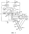
Figure 3 is a simplified schematic diagram illustrating acommunication network 200 according to an embodiment of the present invention. As should be apparent, many components ofnetwork 200 are similar to those present innetwork 100 ofFigures 1 and2 , and similar components are numbered analogously. No implication is intended, however, that the networks or network components are identical except where explicitly stated or apparent from the context. In this light, the configuration ofnetwork 200 will now be explained in more detail. - In this embodiment,
network 200 includes four sources referred to as 210, 215, 220, and 225. As withnetwork 100, these sources may be computing devices, such a personal computers or servers, or they may be considered to represent any other source of data traffic, such as another portion of a network. Each source ofnetwork 200 is effectively connected to each of the others by two interconnected nodes, referred to inFigure 2 as 230 and 240.Source 210 andsource 215 are in direct communication withnode 230, andsource 220 andsource 225 are in direct communication withnode 240. - As illustrated in
Figure 3 , in this embodiment,nodes Link 5 andLink 6. In addition,node 230 includesports serving Link 1 andLink 2, which are for the purpose of connecting to a third node. Likewise,node 240 includesports serving Link 3 andLink 4, which are also for the purpose of connecting to a third node, that is, the same node that connects tonode 230. Note that there may be more, or in some cases fewer links between the nodes, and that there may be other ports on either node that communicate with entities not mentioned above. - Each of the links shown in
Figure 3 could, of course, form an independent communication path from its respective node port to any port on another node. In accordance with the present invention, however, a new dual-layer link aggregation configuration with be implemented. Dual-layer link aggregation consists of two layers of link aggregation; inner-layer link aggregation and outer-layer link aggregation, with the former being in a sense a subset of the latter. The inner-layer link aggregation includes both a peer link aggregation and distant link aggregation. Peer link aggregation connects one dual-layer link aggregation to the other dual-layer link aggregation, and distant link aggregation connects each of two dual-layer link aggregation nodes to a third node. - In the embodiment of
Figure 3 , the dual-link layer aggregations occur atnode 230 andnode 240, and hence thepeer link aggregation 22 is disposed between them, consisting ofLink 5 andLink 6. Note that peer link aggregation can be viewed as two separate link aggregations, one at two ports ofnode 230, and one at two ports ofnode 240. With respect tonode 230, thedistant link aggregation 21 consists ofLink 1 andLink 2; with respect tonode 240, thedistant link aggregation 23 consists ofLink 3 andLink 4. The peer link integrations and the distant link integrations together make up the outer-layer link aggregation. That is, with respect tonode 230, the outer-layer aggregation 50 consists ofLinks Links node 240, the outer-layer link aggregation 50 consists ofLinks Links - In accordance with this embodiment of the present invention, the peer link aggregation includes a requirement that each packet it transmits between
node 230 andnode 240 include header information having a value corresponding to a source port number and to a packet type. The packet type in this embodiment is either L2 unicast or L2 broadcast. - Once aggregated, each link aggregation may be treated by its respective node as a single (virtual) port. Each link aggregation in this embodiment is coupled with a link aggregator including a hashing algorithm for allocating traffic to be forwarded on the link aggregation on to a specific port. For the peer aggregation link, the aggregator also ensures that each packet contains the proper additionally required header information. Each node includes an L2 hardware lookup table for storing associations between packet sources and specific ports or link aggregations.
-
Figure 4 is a simplified block diagram illustrating apeer node 300 according to an embodiment of the present invention.Peer node 300 is so-called only for the reason that it is intended for creating and forwarding packets on a peer aggregation link of the dual-layer aggregation in accordance with the present invention.Peer node 300 therefore includesport 305 andport 306, which are for communicating with a second peer node over a physical links of some kind. Also present areport 301 andport 302, which are similarly for communicating with a third node (that is, a node that is not a dual-layer link aggregation peer node), which is sometimes referred to herein as a "distant" node. - In the embodiment of
Figure 4 ,port 307 andport 308 are for communicating with data sources outside of the dual-layer link aggregation itself, and are therefore often present (see, for example,Figure 3 ) even though they are not required. If present innode 300, there is no requirement, of course, that they actually be connected to another device. In the embodiment ofFigure 3 ,ports network interfaces CPU 310. Facilitating the receipt and forwarding of data packets, network interfaces 317 and 318 also examine each packet for source and destination information. When a received packet indicates that the port on which it was received is associated with a given source, this association is stored byCPU 310 on L2 hardware lookup table 330. Packets that are received and not yet forwarded are stored in buffer 315, which is also coupled toCPU 310.CPU 310 also controls dual-layer aggregator 320, which allocates traffic on the inner-layer and outer-layer link aggregations. - In accordance with this embodiment of the present invention dual-
layer aggregator 320 includes apeer aggregator 322, which allocates traffic being forwarded on a peer link aggregation. As mentioned above, the peer link aggregator also ensures that each packet contains the proper additionally required header information. Dual-layer aggregator 320 also includes adistant link aggregator 326, which allocates traffic on a distant, that is, non-peer inner-layer link aggregation of the dual-layer link aggregation. Finally, dual-layer aggregator 320 includes an outer-layer link aggregator 324, which allocates traffic on the outer-layer link aggregation of the dual-layer link aggregation. As should be apparent, the outer-layer link aggregation includes the same ports as the peer link aggregation and the distant peer aggregation. Note that in alternate embodiment (not shown, dual-link aggregator 320 need not include separate subcomponents, but rather have a single aggregator arranged to allocate traffic on any of the link aggregations according to instructions from theCPU 310. - In the embodiment of
Figure 4 , the dual-layer aggregator 320 also receives packets from each of the peer, distant, outer layer link aggregations, examines each packet for source and destination information, and may remove unnecessary packet header information when it is no longer necessary. -
Figure 5 is a simplified schematic diagram illustratingcommunication network 200 according to another embodiment of the present invention. As should be apparent, in this embodiment,nodes Figure 3 . In addition, in thisembodiment network 200 includes adistant node 250, which is connected tonode 230 byLink 1 andLink 2, and tonode 240 byLink 3 andLink 4. Inter-node aggregation is used in this embodiment.Node 250 includesinter-node aggregator 251, which allocates traffic on the inter-node link aggregation that includesLinks 1 through 4. Other components analogous to those illustrated inFigure 3 may also be present, but for clarity are not shown inFigure 5 .Inter-node link aggregation 100 is a link aggregation that allowsnode 250 to send traffic, for example, fromsource 205 tosource 210 along two different paths. The first path includes an aggregation ofLinks node 230, and the second path includes aggregations ofLinks Links nodes - Referring to the
network 200 ofFigure 5 , when a packet is received fromsource 210, it is examined and its source and intended destination are determined. If necessary, the L2 hardware lookup table is updated to associate the receiving port with the source indicated in the packet header information. This, of association, of course, will be used to forward other packets received in the future. The L2 hardware lookup table is also consulted to determine on which port to forward the packet received fromsource 210. If the destination is unknown tonode 230, then the packet is flooded on both thepeer link aggregation 22 and thedistant link aggregation 21. - If the forwarding port (or virtual port) is known to be the
peer link aggregation 22, then in accordance with this embodiment of thepresent invention node 230 adds header information, if necessary, indicating packet type, and forwards the packet to peerlink aggregation 22. If the forwarding port is known to be the outer-layer link aggregation 50, then in accordance with this embodiment of thepresent invention node 230 forwards the packet to outer-layer link aggregation 50. Note that in accordance with this embodiment of the present invention, no association with the distant link aggregation will be made, and so the packet received fromsource 210 will not be forwarded on the distant link aggregation except where the destination is unknown and the packet is flooded, as described above. - In accordance with this embodiment of the present invention, packets received in
node 230 from the distant link aggregation are processed as follows. The packets are examined to determine their source and intended destination. If necessary, the source is associated in the L2 hardware lookup table with the outer-layer aggregation 50. Note again that packet sources are not associated in the L2 hardware lookup table with thedistant link aggregation 21. If the intended destination of the packet is unknown, that is, not associated with a port or link aggregation on the L2 hardware lookup table, the packet is flooded to all ports, includingpeer link aggregation 22. In this embodiment, when the packet is forwarded in the peer link aggregation, the flood control limit is not applied and the packet header contains the outer-layer link aggregation 50 as the source port number. If the intended destination of the packet is know to be associated with the peer link aggregation, the packet is forwarded on thepeer link aggregation 22 with the outer-link aggregation 50 as the source port number. - In accordance with this embodiment of the present invention, packets received in
node 230 from thepeer link aggregation 22 are processed as follows. The packets are examined to determine their source and intended destination. If the source port number in the packet header identifies the outer-layer link aggregation 50, then that association is made in the L2 hardware lookup table, otherwise, an association with thepeer link aggregation 22. If the intended packet destination is unknown, the packets are flooded to all ports except thedistant link aggregation 21. If the intended destination is associated with the outer-layer link aggregation 50, then the packets are forwarded on the outer-layer link aggregation, but only using the distant link aggregator, that is, on a port selected according to the distant link has algorithm. In this embodiment, of course, this would not includeLink 5 orLink 6. - Note that although reference is made to
node 230 for the purpose of describing the present invention, it should be apparent thatnode 240 will receive and forward packets in an analogous fashion. - Operation of dual-layer link aggregation will now be examined in more detail in reference to
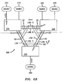
Figures 6a through 6c. Figures 6a through 6c are simplified schematic diagrams illustrating packet flow in thenetwork 200 according to an embodiment of the present invention.Figure 6a illustrates the packet flow whensource 210 is sending packets to source 205, in this case assuming thatsource 205 is unknown to the network. When the packets fromsource 210 arrive innode 230, they are examined to determine their source and destination.Node 230 records in its L2 hardware lookup table the association betweensource 210 and the receiving port. Sincesource 205 is unknown, the packets are flooded to all ports (except the receiving port) as broadcast packets. - A similar process takes place when the packets arrive at
node 240, where an association betweensource 210 andpeer link aggregation 22 will be made in the L2 hardware lookup table. Sincesource 205 is unknown tonode 240, the packets will be flooded. In accordance with this embodiment of the present invention, however, the packets will be flooded to all ports except thedistant link aggregation 23. As noted above, packets received onpeer link aggregation 22 are not flooded on thedistant link aggregation 23. - Here it is also noted that when packets arrive at the
sources - When the packets are received in
node 250, they will be examined to determine their source and destination. An association betweensource 210 andinter-node link aggregation 100 will be made in the L2 hardware lookup table ofnode 250. Sincenode 250 does not associatesource 205 with any port, the packets will be flooded on all ports. Note, however, that in this embodiment this does not include the ports associated withLink 3 andLink 4, since they form part ofinter-node link aggregation 100 on which they were received. The packets will then arrive atsource 205, their intended destination. -
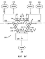
Figure 6b illustrates the packet flow whensource 205 replies to source 210. When the packets arrive atnode 250 fromsource 205, they are examined to determine their source and destination.Node 250 records the association betweensource 205 and the receiving port in its L2 hardware lookup table and, since it associatessource 210 withinter-node link aggregation 100, forwards the packets as unicast packets thereon. Note that this effectively involves a choice between forwarding the packet to eithernode 230 ornode 240; for purposes of illustration, it is assumed that a port leading tonode 240 is chosen. When the packets arrive innode 240, they are examined to determine their source and destination. An association betweensource 205 and outer-layer link aggregation 50 is recorded in the L2 hardware lookup table ofnode 240 and, since an association betweensource 210 andpeer aggregation 22 is known, the packets are forwarded thereon. - In the embodiment of
Figure 6b , when the packets arrive innode 230, they are examined to determine their source and destination. An association betweensource 205 and outer-layer link aggregation 50 is recorded in the L2 hardware lookup table ofnode 230 and, sincesource 210 is associated with a known port, the packets are forwarded thereon. The packets will then arrive atsource 210, their intended destination. -
Figure 6c illustrates the packet flow whensource 210 sends packets to source 205, now a known destination. When the packets formsource 210 arrive innode 230 they are examined, and since an association betweensource 205 and outer-layer link aggregation 50 is known, the packets are forwarded thereon. Note that this effectively involves a choice between sending them tonode 240 ornode 250; for purposes of illustration, it is assumed that a port leading tonode 240 is chosen. When the packets arrive innode 240 from outer-layer link aggregation 50, they are examined. Since an association betweensource 205 anddistant link aggregation 23 is known, the packets are forwarded thereon. When the packets are received atnode 250, they are examined and, sincesource 205 is associated with a known port, the packets are forwarded thereon. The packets will then arrive atsource 205, their intended destination. -
Figures 7a and7b are simplified schematic diagrams illustrating a somewhat different packet flow in thenetwork 200 according to an embodiment of the present invention.Figure 7a illustrates the packet flow whensource 210 is sending packets to source 220, in this case assuming thatsource 220 is unknown to the network. When the packets fromsource 210 arrive innode 230, they are examined to determine their source and destination, and an association betweensource 210 and the receiving port is made in the L2 hardware lookup table. Since no port is currently associated withsource 220, the packets will be flooded on all ports as broadcast packets. When the packets arrive atnode 250, they are examined and an association betweensource 210 andinter-node link aggregation 100 is made in the L2 hardware lookup table. Since no port is currently associated withsource 220, the packets will be flooded on all ports as broadcast packets. Note that in the embodiment of Figure 7c, this does not include any of the ports associated withinter-node link aggregation 100. - In the embodiment of
Figure 7a , when the packets are received atnode 240, they are examined and an association betweensource 210 andpeer aggregation 22 is made in the L2 hardware lookup table. Since no port is currently associated withsource 220, the packets will be flooded on all ports except, in accordance with the present invention,distant link aggregation 23. The packets will then arrive atsource 220, their intended destination. -
Figure 7b illustrates the packet flow whensource 220 replies to source 210. When the packets arrive atnode 240 fromsource 210, they are examined and an association betweensource 220 and the receiving port is made in the L2 hardware lookup table. Sincesource 210 is associates withpeer link aggregate 22, the packets are forwarded thereon. When the packets arrive innode 230, they are examined and an association betweensource 220 and peer link aggregate 22 in the L2 hardware lookup table. Sincesource 220 is associated with a known port, the packets are forwarded thereon. The packets will then arrive atsource 210, their intended destination. -
Figure 8 is a flow diagram illustrating amethod 400 for link aggregation in a communication network node according to an embodiment of the present invention. At START it is presumed that the components necessary to performing the method are available and operational according to the present invention. The process then begins with aggregating a first plurality of node ports (step 405), forming a peer link aggregation to a peer node. In a preferred embodiment, the node is arranged (step not shown) to add header information to each packet forwarded on the first plurality of nodes, the header information comprising a source port number and a packet type. A second plurality of node ports is then aggregated (step 410), the second plurality of node ports forming a distant link aggregation to third node that is also in communication with the peer node. A third plurality of node ports is then aggregated (step 415), forming an outer layer link aggregation including all of the ports in the first plurality of node ports and the second plurality of node ports. Note that the steps ofmethod 400 can be performed in any logically-consistent order, and in some embodiments other steps may be added without departing from the spirit of the invention. - Although multiple embodiments of the present invention have been illustrated in the accompanying Drawings and described in the foregoing Detailed Description, it should be understood that the present invention is not limited to the disclosed embodiments, but is capable of numerous rearrangements, modifications and substitutions without departing from the invention as set forth and defined by the following claims.
Claims (10)
- A method for link aggregation in a communication network node, named first node (230), comprising:aggregating a first plurality of node ports (305, 306) of said first node (230), the first plurality of node ports (305, 306) for communicating with a second node (240) ;aggregating a second plurality of node ports (301, 302) of the first node (230), the second plurality of node ports (301, 302) for communicating with a third node (250); andaggregating a third plurality of node ports , the third plurality of node ports comprising the first plurality of node ports (305, 306) and the second plurality of node ports (301, 302);wherein the second node (240) comprises ports aggregated in the same manner as the first node (230), by the steps of:aggregating a first plurality of node ports of said second node (240), the first plurality of node ports for communicating with the first node (230) ;aggregating a second plurality of node ports of the second node (240), the second plurality of node ports for communicating with the third node (250); andaggregating a third plurality of node ports of said second node (240), the third plurality of node ports of said second node (240) comprising the first plurality of node ports of said second node (240) and the second plurality of node ports of said second node (240).
- The method of claim 1, wherein the first node (230) is arranged to add header information to each packet forwarded on the first plurality of node ports of said first node (230), the header information comprising a source port number and a packet type.
- The method of claim 1, wherein the third node (250) comprises a plurality of node ports aggregated in an inter-node link aggregation comprising the ports of the third node (250) that communicate with the first node (230) and the second node (240).
- The method of claim 1, wherein the first plurality of node ports (305, 306) of said first node (230) comprises two ports.
- A node (230), named first node, for use in a data communication network (200), comprising:a dual-layer link aggregator (320), comprising:a peer link aggregator for allocating traffic on a peer link aggregation (22) comprising a first plurality of node ports (305, 306) of said first node (230), the peer link aggregation (22) for communicating with a peer node (240), named second node, that also comprises a dual-layer link aggregator similar to the one of said first node (230);a distant link aggregator for allocating traffic on a distant link aggregation (21) comprising a second plurality of node ports (301, 302) of the first node (230), the distant link aggregation (21) for communicating with a third node (250) that is also in communication with the second node (240) ; andan outer-link aggregator for allocating traffic on an outer-layer link aggregation (50) comprising the first plurality of node ports and the second plurality of node ports of said first node (230) ;a CPU (310) coupled to the dual-layer link aggregator of said first node (230);a buffer (BUF) for storing packets that are received at the first node (230); anda Layer 2 hardware lookup table (L2 TABLE) for associating packet sources and destinations with ports or link aggregations of the first node (230).
- The node (230) of claim 5, wherein the dual-layer link aggregator is arranged to examine packets received in the first node (230) to determine their source and their destination.
- The node (230) of claim 6, wherein the peer link aggregator of the dual-layer link aggregator (320) of the first node (230) is arranged to add header information to each packet to be forwarded on the peer link aggregation (22), the header information comprising a source port number and a packet type.
- The node (230) of claim 7, wherein the Layer 2 hardware lookup table (L2 TABLE) does not associate any packet source with the distant link aggregation (23) regardless of the port on which the packet was received.
- The node (230) of claim 8, wherein the peer link aggregator of the dual-layer link aggregator (320) of the first node (230) is arranged to insert a value indicating the outer-layer link aggregation as a source port number into the header of any packet received on the distant link aggregation and for which the destination is not associated with any port on the Layer 2 hardware lookup table (L2 TABLE).
- The node (230) of claim 9, wherein the peer link aggregator of the dual-layer link aggregator (320) of the first node (230) is arranged to insert a value indicating the outer-layer link aggregation as a source port number into the header of any packet received on the distant link aggregation (23) and for which the destination is associated with the peer link aggregation (22) on the Layer 2 hardware lookup table (L2 TABLE).
Applications Claiming Priority (2)
| Application Number | Priority Date | Filing Date | Title |
|---|---|---|---|
| US12/459,348 US8059638B2 (en) | 2009-06-30 | 2009-06-30 | Inter-node link aggregation system and method |
| PCT/US2010/040180 WO2011002706A1 (en) | 2009-06-30 | 2010-06-28 | Inter-node link aggregation system and method |
Publications (2)
| Publication Number | Publication Date |
|---|---|
| EP2449735A1 EP2449735A1 (en) | 2012-05-09 |
| EP2449735B1 true EP2449735B1 (en) | 2013-12-11 |
Family
ID=42751724
Family Applications (1)
| Application Number | Title | Priority Date | Filing Date |
|---|---|---|---|
| EP10732784.3A Active EP2449735B1 (en) | 2009-06-30 | 2010-06-28 | Inter-node link aggregation method and node |
Country Status (6)
| Country | Link |
|---|---|
| US (1) | US8059638B2 (en) |
| EP (1) | EP2449735B1 (en) |
| JP (1) | JP5542927B2 (en) |
| KR (1) | KR101317969B1 (en) |
| CN (1) | CN102474454B (en) |
| WO (1) | WO2011002706A1 (en) |
Families Citing this family (22)
| Publication number | Priority date | Publication date | Assignee | Title |
|---|---|---|---|---|
| US8401026B2 (en) * | 2009-05-18 | 2013-03-19 | Cisco Technology, Inc. | Achieving about an equal number of active links across chassis in a virtual port-channel environment |
| US8780911B2 (en) * | 2009-10-08 | 2014-07-15 | Force10 Networks, Inc. | Link aggregation based on port and protocol combination |
| US8122127B2 (en) | 2009-12-31 | 2012-02-21 | Juniper Networks, Inc. | Automatic aggregation of inter-device ports/links in a virtual device |
| US8380904B2 (en) * | 2010-03-09 | 2013-02-19 | Qualcomm Incorporated | Interconnect coupled to master device via at least two different bidirectional connections |
| US8442064B2 (en) * | 2010-03-19 | 2013-05-14 | Juniper Networks, Inc. | Virtual link aggregation of network traffic in an aggregation switch |
| US8625435B2 (en) * | 2010-09-17 | 2014-01-07 | Verizon Patent And Licensing Inc. | Generating and allocating performance monitoring traffic |
| CN102752187B (en) | 2011-04-21 | 2018-02-13 | 中兴通讯股份有限公司 | The method and system of elastic network interface |
| WO2013127414A1 (en) * | 2012-03-02 | 2013-09-06 | Telefonaktiebolaget L M Ericsson (Publ) | Technique for bundling in link aggregation |
| CN102647355B (en) | 2012-04-12 | 2014-11-05 | 华为技术有限公司 | LACP (Link Aggregation Control Protocol) consultation processing method, relay node and system |
| US9036629B2 (en) * | 2012-04-27 | 2015-05-19 | Hewlett-Packard Development Company, L.P. | Switch module |
| US9225549B2 (en) | 2012-08-06 | 2015-12-29 | Lenovo Enterprise Solutions (Singapore) Pte. Ltd. | Multi-chassis link aggregation in a distributed virtual bridge |
| CN103731286A (en) * | 2012-10-12 | 2014-04-16 | 中兴通讯股份有限公司 | Method and device for distributing aggregation port IDs |
| US9660901B2 (en) * | 2012-11-14 | 2017-05-23 | Dell Products L.P. | Systems and methods for forming and using a group of link aggregation groups to reduce traffic on interconnect links |
| JP5811995B2 (en) * | 2012-12-10 | 2015-11-11 | 日立金属株式会社 | Communication system and network relay device |
| US9866470B2 (en) | 2014-01-24 | 2018-01-09 | Red Hat, Inc. | Multiple active link aggregators |
| CN104092604B (en) * | 2014-07-02 | 2018-02-09 | 新华三技术有限公司 | message transmission control method and device |
| US10673744B2 (en) | 2015-09-23 | 2020-06-02 | Extreme Networks, Inc. | Methods, systems, and computer readable media for advanced distribution in a link aggregation group |
| US10972380B2 (en) * | 2016-04-05 | 2021-04-06 | Versa Networks, Inc. | Method for configuring a connection using redundant service nodes |
| CN107547412B (en) * | 2017-05-24 | 2020-05-12 | 新华三技术有限公司 | STP calculation method and device |
| US10476815B2 (en) * | 2017-12-11 | 2019-11-12 | Ciena Corporation | Adaptive communication network with cross-point switches |
| US10680964B1 (en) | 2018-11-26 | 2020-06-09 | Mellanox Technologies Tlv Ltd. | Rate limiting in a multi-chassis environment by exchanging information between peer network elements |
| CN112100008B (en) * | 2020-11-09 | 2021-06-18 | 杭州沃趣科技股份有限公司 | Cross-node multilink redundancy protection method and system |
Family Cites Families (15)
| Publication number | Priority date | Publication date | Assignee | Title |
|---|---|---|---|---|
| US5764740A (en) * | 1995-07-14 | 1998-06-09 | Telefonaktiebolaget Lm Ericsson | System and method for optimal logical network capacity dimensioning with broadband traffic |
| KR100411595B1 (en) * | 2001-12-24 | 2003-12-18 | 엘지전자 주식회사 | Method For Aggregating Link Information In The Private Network To Network Interface |
| US20050180749A1 (en) * | 2003-11-07 | 2005-08-18 | Bikash Koley | System and method for a resilient optical Ethernet networksupporting automatic protection switching |
| KR100563658B1 (en) * | 2003-11-20 | 2006-03-23 | 한국전자통신연구원 | Link-aggregation device and method |
| FR2873524B1 (en) * | 2004-07-22 | 2006-10-27 | Alcatel Sa | LOCAL NETWORK WITH VIRTUAL GROUP (S) OF HEART EQUIPMENT WHICH IS CLEAR AT THE LEVEL TWO SWITCHING |
| KR20060072990A (en) * | 2004-12-24 | 2006-06-28 | 엘지노텔 주식회사 | Apparatus and method for link aggregation control protocol in communication system |
| WO2006107087A1 (en) * | 2005-03-31 | 2006-10-12 | Nec Corporation | Method for enlarging communication network, node and communication band, and communication band enlarging program |
| JP4593484B2 (en) * | 2006-02-03 | 2010-12-08 | アラクサラネットワークス株式会社 | Data communication system and method |
| US8107382B2 (en) * | 2006-03-31 | 2012-01-31 | Avaya Holdings Limited | Loop detection in a communications network |
| JP2007274305A (en) * | 2006-03-31 | 2007-10-18 | Nec Corp | Ring network, communication device, and method of managing operation used therefor |
| KR100889753B1 (en) * | 2006-12-01 | 2009-03-24 | 한국전자통신연구원 | Method of protection switching for link aggregation group and Apparatus thereof |
| JP4862743B2 (en) * | 2007-05-17 | 2012-01-25 | 日本電気株式会社 | Node, communication method and node program |
| US7756029B2 (en) * | 2007-05-24 | 2010-07-13 | Harris Stratex Networks Operating Corporation | Dynamic load balancing for layer-2 link aggregation |
| US8295181B2 (en) * | 2009-03-30 | 2012-10-23 | Cisco Technology, Inc. | Transfer of network traffic for multi-homed devices |
| US8401026B2 (en) * | 2009-05-18 | 2013-03-19 | Cisco Technology, Inc. | Achieving about an equal number of active links across chassis in a virtual port-channel environment |
-
2009
- 2009-06-30 US US12/459,348 patent/US8059638B2/en not_active Expired - Fee Related
-
2010
- 2010-06-28 JP JP2012518565A patent/JP5542927B2/en not_active Expired - Fee Related
- 2010-06-28 WO PCT/US2010/040180 patent/WO2011002706A1/en active Application Filing
- 2010-06-28 KR KR1020117031597A patent/KR101317969B1/en active IP Right Grant
- 2010-06-28 CN CN201080029515.4A patent/CN102474454B/en active Active
- 2010-06-28 EP EP10732784.3A patent/EP2449735B1/en active Active
Also Published As
| Publication number | Publication date |
|---|---|
| KR20120036903A (en) | 2012-04-18 |
| CN102474454B (en) | 2015-05-20 |
| JP5542927B2 (en) | 2014-07-09 |
| US20100329147A1 (en) | 2010-12-30 |
| JP2012532530A (en) | 2012-12-13 |
| WO2011002706A1 (en) | 2011-01-06 |
| US8059638B2 (en) | 2011-11-15 |
| KR101317969B1 (en) | 2013-10-14 |
| CN102474454A (en) | 2012-05-23 |
| EP2449735A1 (en) | 2012-05-09 |
Similar Documents
| Publication | Publication Date | Title |
|---|---|---|
| EP2449735B1 (en) | Inter-node link aggregation method and node | |
| CN114073052B (en) | Systems, methods, and computer readable media for slice-based routing | |
| US10594512B2 (en) | Access network dual path connectivity | |
| EP2911348B1 (en) | Control device discovery in networks having separate control and forwarding devices | |
| US8009684B2 (en) | High capacity ring communication network | |
| US9887917B2 (en) | Port extender | |
| EP3042476B1 (en) | Buffer-less virtual routing | |
| JP4076586B2 (en) | Systems and methods for multilayer network elements | |
| EP2618521B1 (en) | Method, apparatus and system for link aggregation failure protection | |
| US7801028B2 (en) | Method and apparatus for transparent auto-recovery in chain and ring networks | |
| US8462636B2 (en) | Systems and methods for communication of management traffic over link aggregation group interface for a network element with distributed architecture | |
| US8861338B2 (en) | Routed split multilink trunking for IPv6 | |
| WO2021174985A1 (en) | Sr policy issuing method and apparatus and sr policy receiving method and apparatus | |
| US20140369230A1 (en) | Virtual Chassis Topology Management | |
| US20110299551A1 (en) | Method and Apparatus for Transferring Data Packets Between a First Network and a Second Network | |
| JP5429179B2 (en) | Network node and load balancing method thereof | |
| US20100246404A1 (en) | Transfer of network traffic for multi-homed devices | |
| US8446818B2 (en) | Routed split multi-link trunking resiliency for wireless local area network split-plane environments | |
| KR102011021B1 (en) | Method and framework for traffic engineering in network hypervisor of sdn-based network virtualization platform | |
| EP3474504B1 (en) | Leaf-to-spine uplink bandwidth advertisement to leaf-connected servers | |
| EP1964330B1 (en) | Method for reducing fault detection time in a telecommunication network | |
| US10382323B1 (en) | Flooding-based routing protocol having label switched path session information | |
| Kanagavelu et al. | A pro-active and adaptive mechanism for fast failure recovery in SDN data centers | |
| Wang et al. | Cooperative flow management in multi-domain SDN-based networks with multiple controllers | |
| WO2022012145A1 (en) | Load balancing method, apparatus and system |
Legal Events
| Date | Code | Title | Description |
|---|---|---|---|
| PUAI | Public reference made under article 153(3) epc to a published international application that has entered the european phase |
Free format text: ORIGINAL CODE: 0009012 |
|
| 17P | Request for examination filed |
Effective date: 20120130 |
|
| AK | Designated contracting states |
Kind code of ref document: A1 Designated state(s): AL AT BE BG CH CY CZ DE DK EE ES FI FR GB GR HR HU IE IS IT LI LT LU LV MC MK MT NL NO PL PT RO SE SI SK SM TR |
|
| DAX | Request for extension of the european patent (deleted) | ||
| 17Q | First examination report despatched |
Effective date: 20121019 |
|
| REG | Reference to a national code |
Ref country code: DE Ref legal event code: R079 Ref document number: 602010012354 Country of ref document: DE Free format text: PREVIOUS MAIN CLASS: H04L0012560000 Ipc: H04L0012701000 |
|
| GRAP | Despatch of communication of intention to grant a patent |
Free format text: ORIGINAL CODE: EPIDOSNIGR1 |
|
| RIC1 | Information provided on ipc code assigned before grant |
Ipc: H04L 12/701 20130101AFI20130318BHEP Ipc: H04L 12/709 20130101ALI20130318BHEP Ipc: H04L 12/705 20130101ALI20130318BHEP |
|
| INTG | Intention to grant announced |
Effective date: 20130423 |
|
| GRAP | Despatch of communication of intention to grant a patent |
Free format text: ORIGINAL CODE: EPIDOSNIGR1 |
|
| INTG | Intention to grant announced |
Effective date: 20130814 |
|
| 111Z | Information provided on other rights and legal means of execution |
Free format text: AL AT BE BG CH CY CZ DE DK EE ES FI FR GB GR HR HU IE IS IT LI LT LU LV MC MK MT NL NO PL PT RO SE SI SK SM TR Effective date: 20130410 |
|
| GRAS | Grant fee paid |
Free format text: ORIGINAL CODE: EPIDOSNIGR3 |
|
| GRAA | (expected) grant |
Free format text: ORIGINAL CODE: 0009210 |
|
| AK | Designated contracting states |
Kind code of ref document: B1 Designated state(s): AL AT BE BG CH CY CZ DE DK EE ES FI FR GB GR HR HU IE IS IT LI LT LU LV MC MK MT NL NO PL PT RO SE SI SK SM TR |
|
| REG | Reference to a national code |
Ref country code: GB Ref legal event code: FG4D |
|
| REG | Reference to a national code |
Ref country code: CH Ref legal event code: EP |
|
| REG | Reference to a national code |
Ref country code: AT Ref legal event code: REF Ref document number: 645070 Country of ref document: AT Kind code of ref document: T Effective date: 20140115 |
|
| REG | Reference to a national code |
Ref country code: IE Ref legal event code: FG4D |
|
| REG | Reference to a national code |
Ref country code: DE Ref legal event code: R096 Ref document number: 602010012354 Country of ref document: DE Effective date: 20140206 |
|
| REG | Reference to a national code |
Ref country code: NL Ref legal event code: VDEP Effective date: 20131211 |
|
| REG | Reference to a national code |
Ref country code: FR Ref legal event code: GC Effective date: 20140306 |
|
| REG | Reference to a national code |
Ref country code: AT Ref legal event code: MK05 Ref document number: 645070 Country of ref document: AT Kind code of ref document: T Effective date: 20131211 |
|
| PG25 | Lapsed in a contracting state [announced via postgrant information from national office to epo] |
Ref country code: HR Free format text: LAPSE BECAUSE OF FAILURE TO SUBMIT A TRANSLATION OF THE DESCRIPTION OR TO PAY THE FEE WITHIN THE PRESCRIBED TIME-LIMIT Effective date: 20131211 Ref country code: NO Free format text: LAPSE BECAUSE OF FAILURE TO SUBMIT A TRANSLATION OF THE DESCRIPTION OR TO PAY THE FEE WITHIN THE PRESCRIBED TIME-LIMIT Effective date: 20140311 Ref country code: FI Free format text: LAPSE BECAUSE OF FAILURE TO SUBMIT A TRANSLATION OF THE DESCRIPTION OR TO PAY THE FEE WITHIN THE PRESCRIBED TIME-LIMIT Effective date: 20131211 Ref country code: SE Free format text: LAPSE BECAUSE OF FAILURE TO SUBMIT A TRANSLATION OF THE DESCRIPTION OR TO PAY THE FEE WITHIN THE PRESCRIBED TIME-LIMIT Effective date: 20131211 Ref country code: LT Free format text: LAPSE BECAUSE OF FAILURE TO SUBMIT A TRANSLATION OF THE DESCRIPTION OR TO PAY THE FEE WITHIN THE PRESCRIBED TIME-LIMIT Effective date: 20131211 Ref country code: NL Free format text: LAPSE BECAUSE OF FAILURE TO SUBMIT A TRANSLATION OF THE DESCRIPTION OR TO PAY THE FEE WITHIN THE PRESCRIBED TIME-LIMIT Effective date: 20131211 |
|
| REG | Reference to a national code |
Ref country code: LT Ref legal event code: MG4D |
|
| PG25 | Lapsed in a contracting state [announced via postgrant information from national office to epo] |
Ref country code: AT Free format text: LAPSE BECAUSE OF FAILURE TO SUBMIT A TRANSLATION OF THE DESCRIPTION OR TO PAY THE FEE WITHIN THE PRESCRIBED TIME-LIMIT Effective date: 20131211 Ref country code: CY Free format text: LAPSE BECAUSE OF FAILURE TO SUBMIT A TRANSLATION OF THE DESCRIPTION OR TO PAY THE FEE WITHIN THE PRESCRIBED TIME-LIMIT Effective date: 20131211 Ref country code: LV Free format text: LAPSE BECAUSE OF FAILURE TO SUBMIT A TRANSLATION OF THE DESCRIPTION OR TO PAY THE FEE WITHIN THE PRESCRIBED TIME-LIMIT Effective date: 20131211 |
|
| PG25 | Lapsed in a contracting state [announced via postgrant information from national office to epo] |
Ref country code: EE Free format text: LAPSE BECAUSE OF FAILURE TO SUBMIT A TRANSLATION OF THE DESCRIPTION OR TO PAY THE FEE WITHIN THE PRESCRIBED TIME-LIMIT Effective date: 20131211 Ref country code: BE Free format text: LAPSE BECAUSE OF FAILURE TO SUBMIT A TRANSLATION OF THE DESCRIPTION OR TO PAY THE FEE WITHIN THE PRESCRIBED TIME-LIMIT Effective date: 20131211 Ref country code: IS Free format text: LAPSE BECAUSE OF FAILURE TO SUBMIT A TRANSLATION OF THE DESCRIPTION OR TO PAY THE FEE WITHIN THE PRESCRIBED TIME-LIMIT Effective date: 20140411 |
|
| REG | Reference to a national code |
Ref country code: CH Ref legal event code: PCOW Free format text: NEW ADDRESS: 148/152 ROUTE DE LA REINE, 92100 BOULOGNE-BILLANCOURT (FR) |
|
| RAP2 | Party data changed (patent owner data changed or rights of a patent transferred) |
Owner name: ALCATEL LUCENT |
|
| PG25 | Lapsed in a contracting state [announced via postgrant information from national office to epo] |
Ref country code: CZ Free format text: LAPSE BECAUSE OF FAILURE TO SUBMIT A TRANSLATION OF THE DESCRIPTION OR TO PAY THE FEE WITHIN THE PRESCRIBED TIME-LIMIT Effective date: 20131211 Ref country code: PL Free format text: LAPSE BECAUSE OF FAILURE TO SUBMIT A TRANSLATION OF THE DESCRIPTION OR TO PAY THE FEE WITHIN THE PRESCRIBED TIME-LIMIT Effective date: 20131211 Ref country code: SK Free format text: LAPSE BECAUSE OF FAILURE TO SUBMIT A TRANSLATION OF THE DESCRIPTION OR TO PAY THE FEE WITHIN THE PRESCRIBED TIME-LIMIT Effective date: 20131211 Ref country code: RO Free format text: LAPSE BECAUSE OF FAILURE TO SUBMIT A TRANSLATION OF THE DESCRIPTION OR TO PAY THE FEE WITHIN THE PRESCRIBED TIME-LIMIT Effective date: 20131211 Ref country code: PT Free format text: LAPSE BECAUSE OF FAILURE TO SUBMIT A TRANSLATION OF THE DESCRIPTION OR TO PAY THE FEE WITHIN THE PRESCRIBED TIME-LIMIT Effective date: 20140411 Ref country code: ES Free format text: LAPSE BECAUSE OF FAILURE TO SUBMIT A TRANSLATION OF THE DESCRIPTION OR TO PAY THE FEE WITHIN THE PRESCRIBED TIME-LIMIT Effective date: 20131211 |
|
| REG | Reference to a national code |
Ref country code: DE Ref legal event code: R097 Ref document number: 602010012354 Country of ref document: DE |
|
| PLBE | No opposition filed within time limit |
Free format text: ORIGINAL CODE: 0009261 |
|
| STAA | Information on the status of an ep patent application or granted ep patent |
Free format text: STATUS: NO OPPOSITION FILED WITHIN TIME LIMIT |
|
| PG25 | Lapsed in a contracting state [announced via postgrant information from national office to epo] |
Ref country code: DK Free format text: LAPSE BECAUSE OF FAILURE TO SUBMIT A TRANSLATION OF THE DESCRIPTION OR TO PAY THE FEE WITHIN THE PRESCRIBED TIME-LIMIT Effective date: 20131211 |
|
| 26N | No opposition filed |
Effective date: 20140912 |
|
| REG | Reference to a national code |
Ref country code: FR Ref legal event code: RG Effective date: 20141016 |
|
| REG | Reference to a national code |
Ref country code: DE Ref legal event code: R097 Ref document number: 602010012354 Country of ref document: DE Effective date: 20140912 |
|
| PG25 | Lapsed in a contracting state [announced via postgrant information from national office to epo] |
Ref country code: LU Free format text: LAPSE BECAUSE OF FAILURE TO SUBMIT A TRANSLATION OF THE DESCRIPTION OR TO PAY THE FEE WITHIN THE PRESCRIBED TIME-LIMIT Effective date: 20140628 Ref country code: MC Free format text: LAPSE BECAUSE OF FAILURE TO SUBMIT A TRANSLATION OF THE DESCRIPTION OR TO PAY THE FEE WITHIN THE PRESCRIBED TIME-LIMIT Effective date: 20131211 |
|
| REG | Reference to a national code |
Ref country code: CH Ref legal event code: PL |
|
| PG25 | Lapsed in a contracting state [announced via postgrant information from national office to epo] |
Ref country code: SI Free format text: LAPSE BECAUSE OF FAILURE TO SUBMIT A TRANSLATION OF THE DESCRIPTION OR TO PAY THE FEE WITHIN THE PRESCRIBED TIME-LIMIT Effective date: 20131211 |
|
| REG | Reference to a national code |
Ref country code: IE Ref legal event code: MM4A |
|
| PG25 | Lapsed in a contracting state [announced via postgrant information from national office to epo] |
Ref country code: CH Free format text: LAPSE BECAUSE OF NON-PAYMENT OF DUE FEES Effective date: 20140630 Ref country code: LI Free format text: LAPSE BECAUSE OF NON-PAYMENT OF DUE FEES Effective date: 20140630 Ref country code: IE Free format text: LAPSE BECAUSE OF NON-PAYMENT OF DUE FEES Effective date: 20140628 |
|
| REG | Reference to a national code |
Ref country code: FR Ref legal event code: PLFP Year of fee payment: 6 |
|
| PG25 | Lapsed in a contracting state [announced via postgrant information from national office to epo] |
Ref country code: MT Free format text: LAPSE BECAUSE OF FAILURE TO SUBMIT A TRANSLATION OF THE DESCRIPTION OR TO PAY THE FEE WITHIN THE PRESCRIBED TIME-LIMIT Effective date: 20131211 |
|
| PG25 | Lapsed in a contracting state [announced via postgrant information from national office to epo] |
Ref country code: SM Free format text: LAPSE BECAUSE OF FAILURE TO SUBMIT A TRANSLATION OF THE DESCRIPTION OR TO PAY THE FEE WITHIN THE PRESCRIBED TIME-LIMIT Effective date: 20131211 |
|
| REG | Reference to a national code |
Ref country code: FR Ref legal event code: PLFP Year of fee payment: 7 |
|
| PG25 | Lapsed in a contracting state [announced via postgrant information from national office to epo] |
Ref country code: BG Free format text: LAPSE BECAUSE OF FAILURE TO SUBMIT A TRANSLATION OF THE DESCRIPTION OR TO PAY THE FEE WITHIN THE PRESCRIBED TIME-LIMIT Effective date: 20131211 Ref country code: GR Free format text: LAPSE BECAUSE OF FAILURE TO SUBMIT A TRANSLATION OF THE DESCRIPTION OR TO PAY THE FEE WITHIN THE PRESCRIBED TIME-LIMIT Effective date: 20140312 Ref country code: IT Free format text: LAPSE BECAUSE OF FAILURE TO SUBMIT A TRANSLATION OF THE DESCRIPTION OR TO PAY THE FEE WITHIN THE PRESCRIBED TIME-LIMIT Effective date: 20131211 |
|
| PG25 | Lapsed in a contracting state [announced via postgrant information from national office to epo] |
Ref country code: TR Free format text: LAPSE BECAUSE OF FAILURE TO SUBMIT A TRANSLATION OF THE DESCRIPTION OR TO PAY THE FEE WITHIN THE PRESCRIBED TIME-LIMIT Effective date: 20131211 Ref country code: HU Free format text: LAPSE BECAUSE OF FAILURE TO SUBMIT A TRANSLATION OF THE DESCRIPTION OR TO PAY THE FEE WITHIN THE PRESCRIBED TIME-LIMIT; INVALID AB INITIO Effective date: 20100628 |
|
| REG | Reference to a national code |
Ref country code: FR Ref legal event code: PLFP Year of fee payment: 8 |
|
| REG | Reference to a national code |
Ref country code: FR Ref legal event code: PLFP Year of fee payment: 9 |
|
| PG25 | Lapsed in a contracting state [announced via postgrant information from national office to epo] |
Ref country code: MK Free format text: LAPSE BECAUSE OF FAILURE TO SUBMIT A TRANSLATION OF THE DESCRIPTION OR TO PAY THE FEE WITHIN THE PRESCRIBED TIME-LIMIT Effective date: 20131211 |
|
| PG25 | Lapsed in a contracting state [announced via postgrant information from national office to epo] |
Ref country code: AL Free format text: LAPSE BECAUSE OF FAILURE TO SUBMIT A TRANSLATION OF THE DESCRIPTION OR TO PAY THE FEE WITHIN THE PRESCRIBED TIME-LIMIT Effective date: 20131211 |
|
| REG | Reference to a national code |
Ref country code: DE Ref legal event code: R079 Ref document number: 602010012354 Country of ref document: DE Free format text: PREVIOUS MAIN CLASS: H04L0012701000 Ipc: H04L0045000000 |
|
| REG | Reference to a national code |
Ref country code: FR Ref legal event code: PLFP Year of fee payment: 13 |
|
| PGFP | Annual fee paid to national office [announced via postgrant information from national office to epo] |
Ref country code: FR Payment date: 20230510 Year of fee payment: 14 Ref country code: DE Payment date: 20230502 Year of fee payment: 14 |
|
| PGFP | Annual fee paid to national office [announced via postgrant information from national office to epo] |
Ref country code: GB Payment date: 20230504 Year of fee payment: 14 |