EP2442010B1 - Led bar - Google Patents
Led bar Download PDFInfo
- Publication number
- EP2442010B1 EP2442010B1 EP20120150665 EP12150665A EP2442010B1 EP 2442010 B1 EP2442010 B1 EP 2442010B1 EP 20120150665 EP20120150665 EP 20120150665 EP 12150665 A EP12150665 A EP 12150665A EP 2442010 B1 EP2442010 B1 EP 2442010B1
- Authority
- EP
- European Patent Office
- Prior art keywords
- led
- colour
- leds
- tube
- board
- Prior art date
- Legal status (The legal status is an assumption and is not a legal conclusion. Google has not performed a legal analysis and makes no representation as to the accuracy of the status listed.)
- Active
Links
- 238000000034 method Methods 0.000 claims abstract description 5
- 239000003086 colorant Substances 0.000 claims description 3
- 238000013500 data storage Methods 0.000 claims description 2
- 238000002955 isolation Methods 0.000 abstract description 8
- 238000001816 cooling Methods 0.000 description 4
- 239000004033 plastic Substances 0.000 description 4
- 238000009432 framing Methods 0.000 description 2
- 239000004417 polycarbonate Substances 0.000 description 2
- 229920000515 polycarbonate Polymers 0.000 description 2
- 230000003466 anti-cipated effect Effects 0.000 description 1
- 238000005260 corrosion Methods 0.000 description 1
- 230000007797 corrosion Effects 0.000 description 1
- 230000009977 dual effect Effects 0.000 description 1
- 238000013101 initial test Methods 0.000 description 1
- 238000009434 installation Methods 0.000 description 1
- 238000004519 manufacturing process Methods 0.000 description 1
- 239000002184 metal Substances 0.000 description 1
- 230000005855 radiation Effects 0.000 description 1
- 238000007493 shaping process Methods 0.000 description 1
Images


Classifications
-
- F—MECHANICAL ENGINEERING; LIGHTING; HEATING; WEAPONS; BLASTING
- F21—LIGHTING
- F21V—FUNCTIONAL FEATURES OR DETAILS OF LIGHTING DEVICES OR SYSTEMS THEREOF; STRUCTURAL COMBINATIONS OF LIGHTING DEVICES WITH OTHER ARTICLES, NOT OTHERWISE PROVIDED FOR
- F21V29/00—Protecting lighting devices from thermal damage; Cooling or heating arrangements specially adapted for lighting devices or systems
- F21V29/50—Cooling arrangements
- F21V29/502—Cooling arrangements characterised by the adaptation for cooling of specific components
- F21V29/507—Cooling arrangements characterised by the adaptation for cooling of specific components of means for protecting lighting devices from damage, e.g. housings
-
- F—MECHANICAL ENGINEERING; LIGHTING; HEATING; WEAPONS; BLASTING
- F21—LIGHTING
- F21S—NON-PORTABLE LIGHTING DEVICES; SYSTEMS THEREOF; VEHICLE LIGHTING DEVICES SPECIALLY ADAPTED FOR VEHICLE EXTERIORS
- F21S10/00—Lighting devices or systems producing a varying lighting effect
- F21S10/02—Lighting devices or systems producing a varying lighting effect changing colors
-
- F—MECHANICAL ENGINEERING; LIGHTING; HEATING; WEAPONS; BLASTING
- F21—LIGHTING
- F21S—NON-PORTABLE LIGHTING DEVICES; SYSTEMS THEREOF; VEHICLE LIGHTING DEVICES SPECIALLY ADAPTED FOR VEHICLE EXTERIORS
- F21S4/00—Lighting devices or systems using a string or strip of light sources
- F21S4/20—Lighting devices or systems using a string or strip of light sources with light sources held by or within elongate supports
- F21S4/28—Lighting devices or systems using a string or strip of light sources with light sources held by or within elongate supports rigid, e.g. LED bars
-
- F—MECHANICAL ENGINEERING; LIGHTING; HEATING; WEAPONS; BLASTING
- F21—LIGHTING
- F21V—FUNCTIONAL FEATURES OR DETAILS OF LIGHTING DEVICES OR SYSTEMS THEREOF; STRUCTURAL COMBINATIONS OF LIGHTING DEVICES WITH OTHER ARTICLES, NOT OTHERWISE PROVIDED FOR
- F21V13/00—Producing particular characteristics or distribution of the light emitted by means of a combination of elements specified in two or more of main groups F21V1/00 - F21V11/00
- F21V13/02—Combinations of only two kinds of elements
- F21V13/04—Combinations of only two kinds of elements the elements being reflectors and refractors
-
- F—MECHANICAL ENGINEERING; LIGHTING; HEATING; WEAPONS; BLASTING
- F21—LIGHTING
- F21V—FUNCTIONAL FEATURES OR DETAILS OF LIGHTING DEVICES OR SYSTEMS THEREOF; STRUCTURAL COMBINATIONS OF LIGHTING DEVICES WITH OTHER ARTICLES, NOT OTHERWISE PROVIDED FOR
- F21V23/00—Arrangement of electric circuit elements in or on lighting devices
- F21V23/06—Arrangement of electric circuit elements in or on lighting devices the elements being coupling devices, e.g. connectors
-
- F—MECHANICAL ENGINEERING; LIGHTING; HEATING; WEAPONS; BLASTING
- F21—LIGHTING
- F21V—FUNCTIONAL FEATURES OR DETAILS OF LIGHTING DEVICES OR SYSTEMS THEREOF; STRUCTURAL COMBINATIONS OF LIGHTING DEVICES WITH OTHER ARTICLES, NOT OTHERWISE PROVIDED FOR
- F21V29/00—Protecting lighting devices from thermal damage; Cooling or heating arrangements specially adapted for lighting devices or systems
- F21V29/50—Cooling arrangements
- F21V29/70—Cooling arrangements characterised by passive heat-dissipating elements, e.g. heat-sinks
- F21V29/74—Cooling arrangements characterised by passive heat-dissipating elements, e.g. heat-sinks with fins or blades
-
- F—MECHANICAL ENGINEERING; LIGHTING; HEATING; WEAPONS; BLASTING
- F21—LIGHTING
- F21V—FUNCTIONAL FEATURES OR DETAILS OF LIGHTING DEVICES OR SYSTEMS THEREOF; STRUCTURAL COMBINATIONS OF LIGHTING DEVICES WITH OTHER ARTICLES, NOT OTHERWISE PROVIDED FOR
- F21V29/00—Protecting lighting devices from thermal damage; Cooling or heating arrangements specially adapted for lighting devices or systems
- F21V29/50—Cooling arrangements
- F21V29/70—Cooling arrangements characterised by passive heat-dissipating elements, e.g. heat-sinks
- F21V29/83—Cooling arrangements characterised by passive heat-dissipating elements, e.g. heat-sinks the elements having apertures, ducts or channels, e.g. heat radiation holes
-
- H—ELECTRICITY
- H05—ELECTRIC TECHNIQUES NOT OTHERWISE PROVIDED FOR
- H05B—ELECTRIC HEATING; ELECTRIC LIGHT SOURCES NOT OTHERWISE PROVIDED FOR; CIRCUIT ARRANGEMENTS FOR ELECTRIC LIGHT SOURCES, IN GENERAL
- H05B45/00—Circuit arrangements for operating light-emitting diodes [LED]
-
- H—ELECTRICITY
- H05—ELECTRIC TECHNIQUES NOT OTHERWISE PROVIDED FOR
- H05B—ELECTRIC HEATING; ELECTRIC LIGHT SOURCES NOT OTHERWISE PROVIDED FOR; CIRCUIT ARRANGEMENTS FOR ELECTRIC LIGHT SOURCES, IN GENERAL
- H05B45/00—Circuit arrangements for operating light-emitting diodes [LED]
- H05B45/20—Controlling the colour of the light
-
- F—MECHANICAL ENGINEERING; LIGHTING; HEATING; WEAPONS; BLASTING
- F21—LIGHTING
- F21V—FUNCTIONAL FEATURES OR DETAILS OF LIGHTING DEVICES OR SYSTEMS THEREOF; STRUCTURAL COMBINATIONS OF LIGHTING DEVICES WITH OTHER ARTICLES, NOT OTHERWISE PROVIDED FOR
- F21V21/00—Supporting, suspending, or attaching arrangements for lighting devices; Hand grips
- F21V21/14—Adjustable mountings
- F21V21/30—Pivoted housings or frames
-
- F—MECHANICAL ENGINEERING; LIGHTING; HEATING; WEAPONS; BLASTING
- F21—LIGHTING
- F21V—FUNCTIONAL FEATURES OR DETAILS OF LIGHTING DEVICES OR SYSTEMS THEREOF; STRUCTURAL COMBINATIONS OF LIGHTING DEVICES WITH OTHER ARTICLES, NOT OTHERWISE PROVIDED FOR
- F21V31/00—Gas-tight or water-tight arrangements
- F21V31/03—Gas-tight or water-tight arrangements with provision for venting
-
- F—MECHANICAL ENGINEERING; LIGHTING; HEATING; WEAPONS; BLASTING
- F21—LIGHTING
- F21Y—INDEXING SCHEME ASSOCIATED WITH SUBCLASSES F21K, F21L, F21S and F21V, RELATING TO THE FORM OR THE KIND OF THE LIGHT SOURCES OR OF THE COLOUR OF THE LIGHT EMITTED
- F21Y2103/00—Elongate light sources, e.g. fluorescent tubes
- F21Y2103/10—Elongate light sources, e.g. fluorescent tubes comprising a linear array of point-like light-generating elements
-
- F—MECHANICAL ENGINEERING; LIGHTING; HEATING; WEAPONS; BLASTING
- F21—LIGHTING
- F21Y—INDEXING SCHEME ASSOCIATED WITH SUBCLASSES F21K, F21L, F21S and F21V, RELATING TO THE FORM OR THE KIND OF THE LIGHT SOURCES OR OF THE COLOUR OF THE LIGHT EMITTED
- F21Y2115/00—Light-generating elements of semiconductor light sources
- F21Y2115/10—Light-emitting diodes [LED]
Definitions
- the present invention relates to LED bar modules comprising a number of LED groups, which LED groups comprise a number of LEDs, which LEDs have different colours, which LEDs are electrically connected to a colour controller for generating light of changing colour, which colour controller is connected to a power supply, which is formed as a main printed circuit (8), where the LED groups are placed at a pixel board, which pixel board conducts heat from the LEDs.
- the present invention further concerns a method for calibration of LEDs, where the LEDs are connected to control means, which control means control at least one electric parameter used in relation to the operation of the LEDs, where each LED is connected to its own control circuit.
- US 2006/0002110 disclose a linear LED housing comprising a top part attached to a bottom part by fasteners.
- the power and data are fed through the interior of the lighting unit and the top of the housing includes a slot into which light sources are disposed.
- the housing can be fit with a lens for protecting the light sources or shaping light coming from the light sources.
- the housing may house drive circuitry for a high-voltage and lines for power and data run through the housing.
- a metal plate conducting heat away from the drive circuit board and the light sources are provided transversal inside the housing.
- the housing comprises cooling fins on the outside of the housing for additional cooling for the housing.
- the circuit for high voltage power lines runs through the interior of the housing and there is thus a great risk that current might jump from the high voltage and power lines to the housing causing dangerous ground faults.
- This risk is increased when the LED housing is used in moist and humid environments (e.g. on a cruise ship where the LED housing might get in contact with saltwater), as moist might enter the housing, as it is difficult to seal the upper and bottom part of the housing, causing corrosion to appear at the electrical circuits and thus increasing the risk of current jumps and ground faults.
- the disclosed housing is very complicated to manufacture, as the outer part comprises of an upper part and bottom part which are fasten together by screws.
- the lighting fixture 100 shown in Fig. 1 includes one or more light sources and a controller 105 that is configured to output one or more control signals to drive the light sources so as to generate various intensities of light from the light sources.
- the lighting fixture 100 may also include a memory 114 to store various information.
- the memory 114 may be employed to store one or more lighting commands or programs for execution by the processor 102 (e.g., to generate one or more control signals for the light sources), as well as various types of data useful for generating variable color radiation (e.g., calibration information).
- a further object is to form modules of a LED bar which are easy to connect and which by connection automatically connect both power and data.
- a third object of the invention is to achieve efficient cooling of the LEDs.
- Yet another object is to achieve an efficient electrical isolation between electronic printed circuits and the bar housing.
- a further object of the invention is to store calibration data for each LED both electrically and mechanically close to the actual LED.
- another object of the invention is to achieve wide orientation scope of LED bar.
- Another further object is to form modules of LED which is easy to change the diffuser which can fulfil different beam angle out.
- the object of the invention can be fulfilled with a LED bar module according to claim 4 where the pixel board comprises a memory circuit, in which memory circuit LED calibration data for the LEDs at the board is stored. It is well-known when using LEDs for generating different colours that these LEDs need to be calibrated. The best result is achieved if an intelligent circuit is used where, at first, factory data for the LEDs are known and calibration data are calculated in relation to the number of hours the LED has been in operation. By using these data, it is possible to make an intelligent calibration which is sufficient for the LED for at least a period of operation. Placing these calibration data close to the LEDs assures that the correct data is in place for the right LED during operation. This is especially important with the knowledge that two LEDs do probably not have the same colour result for the same supply current. Therefore, it is necessary to calibrate each individual LED. Recalibration might be performed after a period of operation.
- the LEDs can be formed at a chip, which chip further comprises a memory circuit for storing calibration data for the actual LED.
- the calibration data can be stored in a memory chip which could be formed directly at the LED chip. In this way, the calibration data are stored as close as possible to the actual LED.
- the object of the invention can be fulfilled by storing calibration data as described in claim 1 where calibration data for a colour group is stored in a calibration memory, where each colour group is controlled in accordance with local, stored calibration data during operation.
- the actual calibration data is stored in relation to the actual colour group.
- the calibration data is stored at the same pixel board as the colour group. In this way, the calibration data follows the colour group in both initial tests, during normal use and during repair.
- pixel boards are replaceable without performing any start-up calibration.
- the calibration data for each colour group can comprise at least storage of operational time in relation to the actual colour group power level.
- the wear-out of each colour group can be calculated, and the electric supply parameters for each LED can be adjusted in relation to the wear-out.
- the operational time in relation to the actual power level can be stored in a two-dimensional historic file in the calibration data storage.
- only a small number of data needs to be stored in the calibration memory.
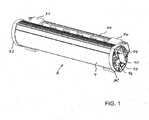
- Figure 1 shows a LED bar module 2 comprising a tube 4 in which tube 4 lighting means in form of LEDs are placed together with control electronics for controlling the light emission of the LEDs. Furthermore, figure 1 shows a first end plate 20 and a second end plate 22. A fixture 24 is connected to framing means 26. A printed circuit connector 30 and two bus connectors 32 and 34 are also shown. Furthermore, in this figure, a valve 36 is shown which valve comprises a diaphragm which diaphragm only allows humidity to pass in the direction inside out from the LED module 2.
- the LED module 2 In operation, power will be connected to the LED module 2 by the connector 30 and data will be connected to connectors 34 or 36. Thus, the LED module will receive sufficient power and information to start performing a light show where colour change is only one of several possibilities.
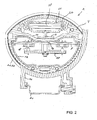
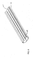
- Figure 2 shows a sectional view of a LED bar 2.
- the housing 4 forms a seat for the pixel board 6 which is heat conductively connected to the tube 4.
- a main printed board 8 and a daughter printed board 10 are shown inside the tube 4 in the cavity. Both printed boards 8 and 10 are placed inside an isolation cover 12 which isolation cover 12 has an opening 60 ( figure 6 ) in which a protrusion 16 of the tube 4 is heat conductively connected to the main printed circuit board 8.
- the daughter circuit board 10 is connected to the main printed circuit board 8 by a connector 18. Outside the tube 4, first and second end covers 20 and 22 are indicated.
- reflectors 58 are seen which reflectors 58 are placed beneath a cover 64, and a second cover 66, which is formed of clear plastic such as poly carbonate.
- the second cover 66 seals the tube 4.
- the tube 4 is connected to a frame 26 which is further connected to holding means 24.
- the heat generated at the pixel board 6 will be conducted into the tube 4. Further heat produced at the main printed circuit board 8 will also be conducted into the tube 4.
- the tube 4 as such is heat conductively connected to the frame 26 from where the heat is radiated or converted outside to the surroundings.
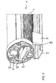
- Figure 3 shows a LED bar 2 seen from a first end.
- Figure 3 shows the tube 4 connected to the first end cover 20.
- the tube 4 is connected to a frame 26 which is further connected to a holder 24.
- a printed circuit board connector 30 is seen and above the PCB connector 30, two data bus connectors 32 and 34 are seen.
- a valve 36 is seen comprising a diaphragm which only allows humidity to pass from the inside to the outside of the tube.
- the valve 36 allows air to pass from inside out which takes place each time the LED module is connected to power and starts to operate.
- the module heats up, and air flows out of the operators.
- the LED module After shutting down, the LED module will start cooling down, and air from the outside will be sucked into the cavity.
- the air subsequently passes through the diaphragm in the valve 36 humidity is left outside and in this way the internal volume will be kept dry.
- Figure 4 shows the opposite end of a LED module 2, and this time the second end cover 22 is indicated. Again the tube 4 is mechanically connected to framing means 26 which are connected to a holder 24.
- the end cover shows a female printed circuit board connector 40 and female data bus connectors 42 and 44.
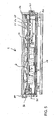
- Figure 5 shows a longitudinal sectional view of a LED bar 2 which bar is formed of a tube 4.
- a pixel board 6 and a main printed circuit board 8 are indicated.
- a daughter printed circuit board 10 is seen.
- an end cover 20 is seen and at the opposite end, an end cover 22 is seen.
- Beneath the tube 4, a frame 26 and a holder 24 are seen.
- a printed circuit board connector 30 and valve 36 are indicated.
- the female connector 40 is seen.
- connectors 50 and 52 are seen which are electrically interconnecting the main board 8 and the pixel board 6.
- LEDs 54 are seen which are placed beneath lenses 56 which lenses 56 are cooperating with reflectors 58.
- Light generated from LEDs 54 is at first deflected by lenses 56 in a direction which is longitudinal in relation to the bar.
- the light which leaves the lenses 56 is then reflected upwards by reflectors 58 with the result that the light leaving the bar is mainly transmitted perpendicular to the bar.
- reflectors 58 By forming the reflectors 58 as a long section with steps between forming reflecting surfaces at the steps, it is possible to let a single group of LEDs light up a relatively long distance of the module. In this way, this module only indicates three groups of LEDs. But seen from the outside, the LED will light up the whole bar.
- Figure 6 shows an isolating cover 12 which isolating cover has a longitudinal opening 60. Furthermore, the isolation cover 12 has a recess 62 at both sides which cooperates with the inner contour of the tube 4 seen in figure 2 .
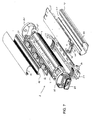
- Figure 7 shows an exploded view of the LED bar 2 which comprises a tube 4 where a pixel board 6 is placed in a recess in the tube 4.
- a main printed circuit board 8 is placed inside an isolation cover 12.
- the tube 4 is connected to a first end cover 20 and a second end cover 22.
- the tube 4 is connected to a frame 26 which frame is further connected to a holder 24.
- female connectors 40 for power and further female data connectors 42 and 44 are seen.
- lenses 56 and reflectors 58 are seen.
- a first cover 64 and a second plastic cover 66 are indicated.
- the isolation cover 12 comprises an opening 60 and the recess 62.
- an end cover 69 is indicated which is cooperating with the end cover 22.
- Figure 8 shows a pixel board 6 on which pixel board a connector 50 is indicated. Furthermore, at the pixel board, LEDs 54 are seen which are placed in groups where each group comprises four LEDs. In addition, memory components 53 and 55 for storing LED calibration data at the board are shown.
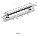
- Figure 9 shows a LED bar 2 which is partly opened in one end.
- the tube 4 is seen and inside the tube 4, the isolation cover 12 is indicated which comprises the main printed circuit board.
- the frame 26 is seen outside the tube 4.
- the end cover 20 covers the first end of the tube and the second end cover is supposed to cover the other end when the tube is correctly assembled.
- the top cover which is made of a clear plastic 66 is seen and below that cover, the cover 64 is also indicated.
- FIG 10 , 11 and 12 show another embodiment of the invention. From Fig10 and Fig 12 , it is seen that LED bar modules 102 comprising a heat conductive tube 104, in which tube 104 and lighting means in form of LEDs are placed together. Power supply 108 and colour controller 110 for controlling the light emission of the LEDs are placed outside of the LED bar modules 102. Furthermore, Fig 10 shows a first end plate 120 and a second end plate 122. A first pivot 184 and a second pivot 186 connect the LED bar modules to rail 124 through the first bracket 180 and the second bracket 182. Two knobs 181 and 183 are on the seat of the bracket 180 and 182. LED bar modules 102 is capable of being rotated manually around the dual pivot 184 and 186.After the anticipated position is reached, to move the knob 181 and 183 toward the tube 104 to fasten or away the tube 104 to loosen can secure the orientation.
- the LED module 102 In operation, power and data will be connected to the LED module 102 by the cable 118. Thus, the LED module will receive sufficient power and information to start performing a light show where colour change is only one of several possibilities.
- Figure11 shows a cross-section view of a LED bar 2.
- the tube 4 forms a seat for the pixel board 106 which is heat conductively connected to the tube 106.
- a LEDs 154 can be placed beneath lenses 156 for deflecting generated light, diffuser 185 is seen which is placed beneath a cover 166 which is formed of transparent or translucent plastic such as poly carbonate.
- the heat generated at the pixel board 106 will be conducted into the tube 104.
- the tube 104 as such is heat conductively connected to the bracket of integrated pivot and further connected to a rail 124 from where the heat is radiated or converted outside to the surroundings.
- a pair of shims 187 and 188 is placed inside of the cover166 to hold the diffuser 185.
- a diffuser film 185 with a certain light angle can be hold by the shims.
- Fig12 shows a plurality of LED bar modules 102 are combined together to form a long strip light.
- the LED bar modules 102 can be aligned through a clamp190.
- the cable 118 integrated power and data is extended from the inside of the tube 104 to the power supply 108 and colour controller 110 which are placed outside of the tube 104.
- the cable 118 is a CAT5e network cable.
- the colour controller 110 can be a common controller for an array of LED bar modules.
Landscapes
- Engineering & Computer Science (AREA)
- General Engineering & Computer Science (AREA)
- Led Device Packages (AREA)
- Arrangement Of Elements, Cooling, Sealing, Or The Like Of Lighting Devices (AREA)
- Led Devices (AREA)
Abstract
Description
- The present invention relates to LED bar modules comprising a number of LED groups, which LED groups comprise a number of LEDs, which LEDs have different colours, which LEDs are electrically connected to a colour controller for generating light of changing colour, which colour controller is connected to a power supply, which is formed as a main printed circuit (8), where the LED groups are placed at a pixel board, which pixel board conducts heat from the LEDs.
- The present invention further concerns a method for calibration of LEDs, where the LEDs are connected to control means, which control means control at least one electric parameter used in relation to the operation of the LEDs, where each LED is connected to its own control circuit.
-
US 2006/0002110 disclose a linear LED housing comprising a top part attached to a bottom part by fasteners. The power and data are fed through the interior of the lighting unit and the top of the housing includes a slot into which light sources are disposed. The housing can be fit with a lens for protecting the light sources or shaping light coming from the light sources. In embodiments the housing may house drive circuitry for a high-voltage and lines for power and data run through the housing. A metal plate conducting heat away from the drive circuit board and the light sources are provided transversal inside the housing. The housing comprises cooling fins on the outside of the housing for additional cooling for the housing. The circuit for high voltage power lines runs through the interior of the housing and there is thus a great risk that current might jump from the high voltage and power lines to the housing causing dangerous ground faults. This risk is increased when the LED housing is used in moist and humid environments (e.g. on a cruise ship where the LED housing might get in contact with saltwater), as moist might enter the housing, as it is difficult to seal the upper and bottom part of the housing, causing corrosion to appear at the electrical circuits and thus increasing the risk of current jumps and ground faults. Further the disclosed housing is very complicated to manufacture, as the outer part comprises of an upper part and bottom part which are fasten together by screws. -
WO2006127785 discloses modular lighting fixtures that allow convenient installation and removal of LED-based light-generating modules and controller modules. The lighting fixture 100 shown inFig. 1 includes one or more light sources and a controller 105 that is configured to output one or more control signals to drive the light sources so as to generate various intensities of light from the light sources. The lighting fixture 100 may also include amemory 114 to store various information. For example, thememory 114 may be employed to store one or more lighting commands or programs for execution by the processor 102 (e.g., to generate one or more control signals for the light sources), as well as various types of data useful for generating variable color radiation (e.g., calibration information). - It is the object of the invention to achieve a highly efficient LED bar for generating a bar of light. A further object is to form modules of a LED bar which are easy to connect and which by connection automatically connect both power and data. A third object of the invention is to achieve efficient cooling of the LEDs. Yet another object is to achieve an efficient electrical isolation between electronic printed circuits and the bar housing. A further object of the invention is to store calibration data for each LED both electrically and mechanically close to the actual LED. And yet, another object of the invention is to achieve wide orientation scope of LED bar. Another further object is to form modules of LED which is easy to change the diffuser which can fulfil different beam angle out.
- The object of the invention can be fulfilled with a LED bar module according to
claim 4 where the pixel board comprises a memory circuit, in which memory circuit LED calibration data for the LEDs at the board is stored. It is well-known when using LEDs for generating different colours that these LEDs need to be calibrated. The best result is achieved if an intelligent circuit is used where, at first, factory data for the LEDs are known and calibration data are calculated in relation to the number of hours the LED has been in operation. By using these data, it is possible to make an intelligent calibration which is sufficient for the LED for at least a period of operation. Placing these calibration data close to the LEDs assures that the correct data is in place for the right LED during operation. This is especially important with the knowledge that two LEDs do probably not have the same colour result for the same supply current. Therefore, it is necessary to calibrate each individual LED. Recalibration might be performed after a period of operation. - Instead the LEDs can be formed at a chip, which chip further comprises a memory circuit for storing calibration data for the actual LED. As an alternative, the calibration data can be stored in a memory chip which could be formed directly at the LED chip. In this way, the calibration data are stored as close as possible to the actual LED.
- The object of the invention can be fulfilled by storing calibration data as described in claim 1 where calibration data for a colour group is stored in a calibration memory, where each colour group is controlled in accordance with local, stored calibration data during operation.
- Hereby, it can be achieved that the actual calibration data is stored in relation to the actual colour group. The calibration data is stored at the same pixel board as the colour group. In this way, the calibration data follows the colour group in both initial tests, during normal use and during repair. Hereby, pixel boards are replaceable without performing any start-up calibration.
- The calibration data for each colour group can comprise at least storage of operational time in relation to the actual colour group power level. Hereby, the wear-out of each colour group can be calculated, and the electric supply parameters for each LED can be adjusted in relation to the wear-out.
- The operational time in relation to the actual power level can be stored in a two-dimensional historic file in the calibration data storage. Hereby, only a small number of data needs to be stored in the calibration memory.
-
-
Figure 1 shows a LED bar module -
Figure 2 shows a sectional view of a LED bar -
Figure 3 shows aLED bar 2 seen from a first end -
Figure 4 shows the opposite end of a LED module -
Figure 5 shows a longitudinal sectional view of a LED bar -
Figure 6 shows an isolating cover -
Figure 7 shows an exploded view of the LED bar -
Figure 8 shows a pixel board -
Figure 9 shows aLED bar 2 seen partly opened in one end -
Figure 10 shows an exploded perspective view of another embodiment of LED bar module. -
Figure 11 shows a cross section view of another embodiment of LED bar module with shims: -
Figure 12 shows a plurality of another embodiment LED bar modules combined together. -
Figure 1 shows aLED bar module 2 comprising atube 4 in whichtube 4 lighting means in form of LEDs are placed together with control electronics for controlling the light emission of the LEDs. Furthermore,figure 1 shows afirst end plate 20 and asecond end plate 22. Afixture 24 is connected to framing means 26. A printedcircuit connector 30 and twobus connectors valve 36 is shown which valve comprises a diaphragm which diaphragm only allows humidity to pass in the direction inside out from theLED module 2. - In operation, power will be connected to the
LED module 2 by theconnector 30 and data will be connected toconnectors -
Figure 2 shows a sectional view of aLED bar 2. In a cavity 14, thehousing 4 forms a seat for the pixel board 6 which is heat conductively connected to thetube 4. Inside thetube 4 in the cavity, a main printed board 8 and a daughter printedboard 10 are shown. Both printedboards 8 and 10 are placed inside anisolation cover 12 which isolation cover 12 has an opening 60 (figure 6 ) in which a protrusion 16 of thetube 4 is heat conductively connected to the main printed circuit board 8. Thedaughter circuit board 10 is connected to the main printed circuit board 8 by aconnector 18. Outside thetube 4, first and second end covers 20 and 22 are indicated. Over the pixel board 6,reflectors 58 are seen which reflectors 58 are placed beneath acover 64, and asecond cover 66, which is formed of clear plastic such as poly carbonate. Thesecond cover 66, seals thetube 4. At the outside, thetube 4 is connected to aframe 26 which is further connected to holdingmeans 24. - In operation, the heat generated at the pixel board 6 will be conducted into the
tube 4. Further heat produced at the main printed circuit board 8 will also be conducted into thetube 4. Thetube 4 as such is heat conductively connected to theframe 26 from where the heat is radiated or converted outside to the surroundings. -
Figure 3 shows aLED bar 2 seen from a first end.Figure 3 shows thetube 4 connected to thefirst end cover 20. Thetube 4 is connected to aframe 26 which is further connected to aholder 24. A printedcircuit board connector 30 is seen and above thePCB connector 30, twodata bus connectors valve 36 is seen comprising a diaphragm which only allows humidity to pass from the inside to the outside of the tube. - In operation, the
valve 36 allows air to pass from inside out which takes place each time the LED module is connected to power and starts to operate. The module heats up, and air flows out of the operators. After shutting down, the LED module will start cooling down, and air from the outside will be sucked into the cavity. As the air subsequently passes through the diaphragm in thevalve 36, humidity is left outside and in this way the internal volume will be kept dry. -
Figure 4 shows the opposite end of aLED module 2, and this time thesecond end cover 22 is indicated. Again thetube 4 is mechanically connected to framing means 26 which are connected to aholder 24. The end cover shows a female printedcircuit board connector 40 and femaledata bus connectors - Combining
figure 4 andfigure 3 , it is clear that two or more LED modules can be coupled serial to form a relatively long tube. -
Figure 5 shows a longitudinal sectional view of aLED bar 2 which bar is formed of atube 4. Inside the tube, a pixel board 6 and a main printed circuit board 8 are indicated. Furthermore, a daughter printedcircuit board 10 is seen. At a first end, anend cover 20 is seen and at the opposite end, anend cover 22 is seen. Beneath thetube 4, aframe 26 and aholder 24 are seen. At the first end, a printedcircuit board connector 30 andvalve 36 are indicated. At the other end, thefemale connector 40 is seen. Inside the tube,connectors 50 and 52 are seen which are electrically interconnecting the main board 8 and the pixel board 6. Furthermore, at the pixel board,LEDs 54 are seen which are placed beneathlenses 56 whichlenses 56 are cooperating withreflectors 58. - Light generated from
LEDs 54 is at first deflected bylenses 56 in a direction which is longitudinal in relation to the bar. The light which leaves thelenses 56 is then reflected upwards byreflectors 58 with the result that the light leaving the bar is mainly transmitted perpendicular to the bar. By forming thereflectors 58 as a long section with steps between forming reflecting surfaces at the steps, it is possible to let a single group of LEDs light up a relatively long distance of the module. In this way, this module only indicates three groups of LEDs. But seen from the outside, the LED will light up the whole bar. -
Figure 6 shows an isolatingcover 12 which isolating cover has a longitudinal opening 60. Furthermore, theisolation cover 12 has arecess 62 at both sides which cooperates with the inner contour of thetube 4 seen infigure 2 . -
Figure 7 shows an exploded view of theLED bar 2 which comprises atube 4 where a pixel board 6 is placed in a recess in thetube 4. Inside thetube 4 in a cavity, a main printed circuit board 8 is placed inside anisolation cover 12. Thetube 4 is connected to afirst end cover 20 and asecond end cover 22. Furthermore, thetube 4 is connected to aframe 26 which frame is further connected to aholder 24. At the end of the printed main circuit board 8,female connectors 40 for power and furtherfemale data connectors lenses 56 andreflectors 58 are seen. Above thereflectors 58, afirst cover 64 and asecond plastic cover 66 are indicated. Theisolation cover 12 comprises an opening 60 and therecess 62. Furthermore, anend cover 69 is indicated which is cooperating with theend cover 22. -
Figure 8 shows a pixel board 6 on which pixel board aconnector 50 is indicated. Furthermore, at the pixel board,LEDs 54 are seen which are placed in groups where each group comprises four LEDs. In addition,memory components -
Figure 9 shows aLED bar 2 which is partly opened in one end. Thetube 4 is seen and inside thetube 4, theisolation cover 12 is indicated which comprises the main printed circuit board. Also, theframe 26 is seen outside thetube 4. The end cover 20 covers the first end of the tube and the second end cover is supposed to cover the other end when the tube is correctly assembled. The top cover which is made of aclear plastic 66 is seen and below that cover, thecover 64 is also indicated. -
Figure 10 ,11 and12 show another embodiment of the invention. FromFig10 andFig 12 , it is seen thatLED bar modules 102 comprising a heatconductive tube 104, in whichtube 104 and lighting means in form of LEDs are placed together.Power supply 108 andcolour controller 110 for controlling the light emission of the LEDs are placed outside of theLED bar modules 102. Furthermore,Fig 10 shows afirst end plate 120 and asecond end plate 122. Afirst pivot 184 and asecond pivot 186 connect the LED bar modules to rail 124 through thefirst bracket 180 and thesecond bracket 182. Twoknobs bracket LED bar modules 102 is capable of being rotated manually around thedual pivot 184 and 186.After the anticipated position is reached, to move theknob tube 104 to fasten or away thetube 104 to loosen can secure the orientation. - In operation, power and data will be connected to the
LED module 102 by thecable 118. Thus, the LED module will receive sufficient power and information to start performing a light show where colour change is only one of several possibilities. -
Figure11 shows a cross-section view of aLED bar 2. In arecess 114, thetube 4 forms a seat for thepixel board 106 which is heat conductively connected to thetube 106. Over thepixel board 106, aLEDs 154 can be placed beneathlenses 156 for deflecting generated light,diffuser 185 is seen which is placed beneath acover 166 which is formed of transparent or translucent plastic such as poly carbonate. - In operation, the heat generated at the
pixel board 106 will be conducted into thetube 104. Thetube 104 as such is heat conductively connected to the bracket of integrated pivot and further connected to arail 124 from where the heat is radiated or converted outside to the surroundings. - A pair of
shims diffuser 185. Adiffuser film 185 with a certain light angle can be hold by the shims. By adding the different diffuser film in front of Lens will change beam spread angle from 20°to 40°, 60° and 120° or any other. When moving away thefirst end plate 120 and thesecond plate 122, it is easily removable for changing different diffuser films, thus alternative. -
Fig12 shows a plurality ofLED bar modules 102 are combined together to form a long strip light. TheLED bar modules 102 can be aligned through a clamp190. Thecable 118 integrated power and data is extended from the inside of thetube 104 to thepower supply 108 andcolour controller 110 which are placed outside of thetube 104. Preferably, thecable 118 is a CAT5e network cable. Sometimes thecolour controller 110 can be a common controller for an array of LED bar modules.
Claims (7)
- Method for calibration of colour groups, where a colour group comprises at least one LED (54) placed at a pixel board (6), where the colour groups are connected to control means, which control means control at least one physical parameter used in relation to the operation of the colour groups, where each colour group is connected to a control circuit, said control circuit comprises a daughter printed circuit (10) comprising said control means, characterized in that calibration data for a colour group is stored in a calibration memory, where each colour group is controlled in accordance with local, stored calibration data during operation, wherein said calibration memory (53, 55) is placed at said pixel board and in that said daughter printed circuit (10) and said pixel board (6) are separated.
- Method according to claim 1, characterized in that the calibration data for each LED comprises at least storage of operational time in relation to the actual LED power level.
- Method according to claim 2, characterized in that the operational time in relation to the actual power level is stored in a two-dimensional historic file in the calibration data storage.
- LED module comprising a number of LED groups, which LED groups comprise a number of LEDs (54), which LEDs have different colours, which LEDs are electrically connected to a colour controller for generating light, which colour controller is connected to a power supply, where the LEDs are placed at a pixel board characterized in that the pixel board is separated from said colour controller and comprises a memory circuit (53, 55), in which memory circuit LED calibration data for the LEDs at the pixel board are stored.
- LED module according to claim 4 characterized in that at least one LED are formed at a chip, which chip comprises said memory circuit for storing said calibration data.
- LED module according to claims 4-5 characterized in that the pixel board comprises at least on connector (50) for connecting the pixel board to the colour controller.
- LED module according to claims 4-6 characterized in that said LED module comprises a main printed circuit (8) comprising a power supply and electrically and mechanically connected to a daughter printed circuit board (10) by connectors (18), said daughter printed circuit board comprising said colour controller
Applications Claiming Priority (2)
| Application Number | Priority Date | Filing Date | Title |
|---|---|---|---|
| DKPA200701267 | 2007-09-05 | ||
| EP08784442A EP2195573B1 (en) | 2007-09-05 | 2008-09-05 | Led bar |
Related Parent Applications (2)
| Application Number | Title | Priority Date | Filing Date |
|---|---|---|---|
| EP08784442A Division EP2195573B1 (en) | 2007-09-05 | 2008-09-05 | Led bar |
| EP08784442.9 Division | 2008-09-05 |
Publications (3)
| Publication Number | Publication Date |
|---|---|
| EP2442010A2 EP2442010A2 (en) | 2012-04-18 |
| EP2442010A3 EP2442010A3 (en) | 2012-12-19 |
| EP2442010B1 true EP2442010B1 (en) | 2015-05-20 |
Family
ID=40029300
Family Applications (2)
| Application Number | Title | Priority Date | Filing Date |
|---|---|---|---|
| EP08784442A Active EP2195573B1 (en) | 2007-09-05 | 2008-09-05 | Led bar |
| EP20120150665 Active EP2442010B1 (en) | 2007-09-05 | 2008-09-05 | Led bar |
Family Applications Before (1)
| Application Number | Title | Priority Date | Filing Date |
|---|---|---|---|
| EP08784442A Active EP2195573B1 (en) | 2007-09-05 | 2008-09-05 | Led bar |
Country Status (6)
| Country | Link |
|---|---|
| US (2) | US8287144B2 (en) |
| EP (2) | EP2195573B1 (en) |
| CN (2) | CN101836034B (en) |
| AT (1) | ATE546690T1 (en) |
| DK (1) | DK2442010T3 (en) |
| WO (1) | WO2009030233A1 (en) |
Families Citing this family (119)
| Publication number | Priority date | Publication date | Assignee | Title |
|---|---|---|---|---|
| WO2006023149A2 (en) | 2004-07-08 | 2006-03-02 | Color Kinetics Incorporated | Led package methods and systems |
| US8118447B2 (en) | 2007-12-20 | 2012-02-21 | Altair Engineering, Inc. | LED lighting apparatus with swivel connection |
| US9102857B2 (en) | 2008-03-02 | 2015-08-11 | Lumenetix, Inc. | Methods of selecting one or more phase change materials to match a working temperature of a light-emitting diode to be cooled |
| US7810965B2 (en) | 2008-03-02 | 2010-10-12 | Lumenetix, Inc. | Heat removal system and method for light emitting diode lighting apparatus |
| US8360599B2 (en) | 2008-05-23 | 2013-01-29 | Ilumisys, Inc. | Electric shock resistant L.E.D. based light |
| TWM358249U (en) * | 2008-09-01 | 2009-06-01 | Energyled Corp | Structure of lamp tube suitable for LED |
| US8324817B2 (en) | 2008-10-24 | 2012-12-04 | Ilumisys, Inc. | Light and light sensor |
| US8653984B2 (en) | 2008-10-24 | 2014-02-18 | Ilumisys, Inc. | Integration of LED lighting control with emergency notification systems |
| US8214084B2 (en) | 2008-10-24 | 2012-07-03 | Ilumisys, Inc. | Integration of LED lighting with building controls |
| US8901823B2 (en) | 2008-10-24 | 2014-12-02 | Ilumisys, Inc. | Light and light sensor |
| US7938562B2 (en) | 2008-10-24 | 2011-05-10 | Altair Engineering, Inc. | Lighting including integral communication apparatus |
| US7969075B2 (en) | 2009-02-10 | 2011-06-28 | Lumenetix, Inc. | Thermal storage system using encapsulated phase change materials in LED lamps |
| CN102095172A (en) * | 2009-12-15 | 2011-06-15 | 富士迈半导体精密工业(上海)有限公司 | Light emitting diode lamp |
| US8123389B2 (en) * | 2010-02-12 | 2012-02-28 | Lumenetix, Inc. | LED lamp assembly with thermal management system |
| WO2011119921A2 (en) | 2010-03-26 | 2011-09-29 | Altair Engineering, Inc. | Led light with thermoelectric generator |
| CA2794541C (en) | 2010-03-26 | 2018-05-01 | David L. Simon | Inside-out led bulb |
| EP2990718B1 (en) | 2010-04-27 | 2019-06-05 | Cooper Technologies Company | Linkable linear light emitting diode system |
| WO2011139768A2 (en) | 2010-04-28 | 2011-11-10 | Cooper Technologies Company | Linear led light module |
| KR20110121927A (en) * | 2010-05-03 | 2011-11-09 | 삼성엘이디 주식회사 | Illumination apparatus employing the light emitting device package |
| US10883702B2 (en) | 2010-08-31 | 2021-01-05 | Ideal Industries Lighting Llc | Troffer-style fixture |
| EP2633227B1 (en) | 2010-10-29 | 2018-08-29 | iLumisys, Inc. | Mechanisms for reducing risk of shock during installation of light tube |
| US9494293B2 (en) | 2010-12-06 | 2016-11-15 | Cree, Inc. | Troffer-style optical assembly |
| US9581312B2 (en) | 2010-12-06 | 2017-02-28 | Cree, Inc. | LED light fixtures having elongated prismatic lenses |
| US20120176785A1 (en) * | 2011-01-10 | 2012-07-12 | GEM-SUN Technologies Co., Ltd. | Structure improvement of led lamp |
| TWI482565B (en) * | 2011-04-13 | 2015-04-21 | Wistron Corp | A printed circuit board, a supporting jig and a positioning method |
| DE102011050908A1 (en) * | 2011-06-08 | 2012-12-13 | Dietmar Müller | Light-emitting diode lamp and circuit for controlling a light source |
| US9335038B2 (en) | 2011-07-20 | 2016-05-10 | Ip Holdings, Llc | Vertically disposed HID lamp fixture |
| US10823347B2 (en) | 2011-07-24 | 2020-11-03 | Ideal Industries Lighting Llc | Modular indirect suspended/ceiling mount fixture |
| US9072171B2 (en) | 2011-08-24 | 2015-06-30 | Ilumisys, Inc. | Circuit board mount for LED light |
| US9423117B2 (en) | 2011-12-30 | 2016-08-23 | Cree, Inc. | LED fixture with heat pipe |
| US10544925B2 (en) | 2012-01-06 | 2020-01-28 | Ideal Industries Lighting Llc | Mounting system for retrofit light installation into existing light fixtures |
| US9777897B2 (en) | 2012-02-07 | 2017-10-03 | Cree, Inc. | Multiple panel troffer-style fixture |
| US8905575B2 (en) | 2012-02-09 | 2014-12-09 | Cree, Inc. | Troffer-style lighting fixture with specular reflector |
| US9184518B2 (en) | 2012-03-02 | 2015-11-10 | Ilumisys, Inc. | Electrical connector header for an LED-based light |
| KR101177470B1 (en) * | 2012-03-19 | 2012-08-24 | 엘지전자 주식회사 | Lighting apparatus |
| US10054274B2 (en) | 2012-03-23 | 2018-08-21 | Cree, Inc. | Direct attach ceiling-mounted solid state downlights |
| US9310038B2 (en) | 2012-03-23 | 2016-04-12 | Cree, Inc. | LED fixture with integrated driver circuitry |
| US9494294B2 (en) | 2012-03-23 | 2016-11-15 | Cree, Inc. | Modular indirect troffer |
| USD745736S1 (en) * | 2012-04-05 | 2015-12-15 | Michael W. May | Illuminating assembly |
| US9228727B2 (en) | 2012-04-05 | 2016-01-05 | Michael W. May | Lighting assembly |
| US9360185B2 (en) | 2012-04-09 | 2016-06-07 | Cree, Inc. | Variable beam angle directional lighting fixture assembly |
| US9874322B2 (en) | 2012-04-10 | 2018-01-23 | Cree, Inc. | Lensed troffer-style light fixture |
| US8926126B2 (en) * | 2012-04-16 | 2015-01-06 | 3Form, Llc | Adjustable, modular lighting fixture |
| US9204509B2 (en) | 2012-04-20 | 2015-12-01 | 4S Industries, Inc. | System and apparatus for a dual LED light bar |
| US9285099B2 (en) | 2012-04-23 | 2016-03-15 | Cree, Inc. | Parabolic troffer-style light fixture |
| USD770079S1 (en) | 2015-04-02 | 2016-10-25 | Ip Holdings, Llc | Light fixture |
| WO2014005321A1 (en) * | 2012-07-06 | 2014-01-09 | GE Lighting Solutions, LLC | Linear light fixture |
| WO2014008463A1 (en) | 2012-07-06 | 2014-01-09 | Ilumisys, Inc. | Power supply assembly for led-based light tube |
| US8931929B2 (en) | 2012-07-09 | 2015-01-13 | Cree, Inc. | Light emitting diode primary optic for beam shaping |
| US9271367B2 (en) | 2012-07-09 | 2016-02-23 | Ilumisys, Inc. | System and method for controlling operation of an LED-based light |
| DE102013203916A1 (en) * | 2013-03-07 | 2014-09-11 | Zumtobel Lighting Gmbh | Luminaire with a LED light module |
| DE102013102644B4 (en) * | 2013-03-14 | 2018-06-07 | Phoenix Contact Gmbh & Co. Kg | Lighting device with two interfaces and control device and lighting system |
| US10648643B2 (en) | 2013-03-14 | 2020-05-12 | Ideal Industries Lighting Llc | Door frame troffer |
| US9285084B2 (en) | 2013-03-14 | 2016-03-15 | Ilumisys, Inc. | Diffusers for LED-based lights |
| US9052075B2 (en) | 2013-03-15 | 2015-06-09 | Cree, Inc. | Standardized troffer fixture |
| US8974102B2 (en) * | 2013-03-15 | 2015-03-10 | Weekend Concepts, Inc. | Vehicular lighting system |
| US9593835B2 (en) * | 2013-04-09 | 2017-03-14 | Bombardier Transportation Gmbh | LED lighting system for a railway vehicle |
| USD698987S1 (en) | 2013-06-20 | 2014-02-04 | Ip Holdings, Llc | Horticulture grow light housing |
| TW201502430A (en) * | 2013-07-02 | 2015-01-16 | Phihong Technology Co Ltd | LED tube |
| USD745993S1 (en) | 2013-07-09 | 2015-12-22 | Ip Holdings, Llc | Horticulture grow light housing |
| US9750199B2 (en) | 2013-07-18 | 2017-09-05 | Ip Holdings, Llc | Air cooled horticulture lighting fixture |
| USD748849S1 (en) | 2014-06-11 | 2016-02-02 | Ip Holdings, Llc | Sealed optics air cooled grow light |
| US9016907B2 (en) | 2013-07-18 | 2015-04-28 | Ip Holdings, Llc | Air cooled horticulture lighting fixture for a double ended high pressure sodium lamp |
| USD786471S1 (en) | 2013-09-06 | 2017-05-09 | Cree, Inc. | Troffer-style light fixture |
| US9267650B2 (en) | 2013-10-09 | 2016-02-23 | Ilumisys, Inc. | Lens for an LED-based light |
| US8931917B1 (en) * | 2013-10-27 | 2015-01-13 | Shen-Wei Liu | Work light for multi-occasions |
| CN104754798B (en) * | 2013-12-27 | 2017-11-07 | 上海博泰悦臻网络技术服务有限公司 | The brightness control method and device of key-press backlight |
| CN103697361A (en) * | 2014-01-09 | 2014-04-02 | 龚备文 | Ladder-shaped strip lamp |
| KR20160111975A (en) | 2014-01-22 | 2016-09-27 | 일루미시스, 인크. | Led-based light with addressed leds |
| USD772465S1 (en) | 2014-02-02 | 2016-11-22 | Cree Hong Kong Limited | Troffer-style fixture |
| US10451253B2 (en) | 2014-02-02 | 2019-10-22 | Ideal Industries Lighting Llc | Troffer-style fixture with LED strips |
| USD807556S1 (en) | 2014-02-02 | 2018-01-09 | Cree Hong Kong Limited | Troffer-style fixture |
| USD749768S1 (en) | 2014-02-06 | 2016-02-16 | Cree, Inc. | Troffer-style light fixture with sensors |
| US9565769B2 (en) | 2014-02-19 | 2017-02-07 | Elemental LED, Inc. | LED linear lighting kit |
| US9279544B1 (en) * | 2014-02-19 | 2016-03-08 | Elemental LED, Inc. | LED linear lighting strip |
| US10527225B2 (en) | 2014-03-25 | 2020-01-07 | Ideal Industries, Llc | Frame and lens upgrade kits for lighting fixtures |
| AU2015247456B2 (en) | 2014-04-18 | 2020-05-07 | Dva Holdings Llc | Lighting assembly |
| US9702531B2 (en) | 2014-04-23 | 2017-07-11 | General Led, Inc. | Retrofit system and method for replacing linear fluorescent lamp with LED modules |
| US9510400B2 (en) | 2014-05-13 | 2016-11-29 | Ilumisys, Inc. | User input systems for an LED-based light |
| DE102015000733A1 (en) | 2014-07-29 | 2016-02-04 | Seifert Mtmsystems (Malta) Ltd. | Control cabinet luminaire with light sources based on light-emitting diodes |
| USD732235S1 (en) | 2014-08-07 | 2015-06-16 | Ip Holdings, Llc | Horticulture grow light |
| USD732236S1 (en) | 2014-09-11 | 2015-06-16 | Ip Holdings, Llc | Light fixture |
| US9949348B2 (en) * | 2014-11-10 | 2018-04-17 | LIFI Labs, Inc. | Lighting connectivity module |
| USD751245S1 (en) | 2014-12-11 | 2016-03-08 | Ip Holdings, Llc | Horticulture grow light |
| TWM498841U (en) * | 2014-12-30 | 2015-04-11 | Bo-Heng Lin | Simple shockproof lamp holder |
| USD757346S1 (en) | 2015-01-08 | 2016-05-24 | Ip Holdings, Llc | Horticulture grow light |
| EP3051205B1 (en) * | 2015-02-02 | 2017-05-24 | LG Electronics Inc. | Lighting device |
| USD773107S1 (en) | 2015-04-13 | 2016-11-29 | Ip Holdings, Llc | Horticulture grow light |
| USD769513S1 (en) | 2015-04-15 | 2016-10-18 | Ip Holdings, Llc | Light fixture |
| EP3089553B1 (en) * | 2015-04-29 | 2019-06-12 | Harman Professional Denmark ApS | Light system with improved color control |
| US10161568B2 (en) | 2015-06-01 | 2018-12-25 | Ilumisys, Inc. | LED-based light with canted outer walls |
| USD770670S1 (en) | 2015-06-24 | 2016-11-01 | Ip Holdings, Llc | Horticulture grow light |
| US10012354B2 (en) | 2015-06-26 | 2018-07-03 | Cree, Inc. | Adjustable retrofit LED troffer |
| US10139073B2 (en) | 2015-07-23 | 2018-11-27 | Quadratec, Inc. | Light emitting diode (LED) light bar |
| US10465896B2 (en) * | 2015-12-28 | 2019-11-05 | ETi Solid State Lighting Inc. | Linkable lighting systems |
| US10352510B2 (en) | 2015-12-28 | 2019-07-16 | ETi Solid State Lighting Inc. | Linkable lighting fixture |
| USD780985S1 (en) | 2016-01-05 | 2017-03-07 | Ip Holdings, Llc | Light fixture |
| IL260463B2 (en) | 2016-01-07 | 2023-11-01 | Michael W May | Connector system for lighting assembly |
| USD780986S1 (en) | 2016-01-07 | 2017-03-07 | Ip Holdings, Llc | Light fixture |
| US9644828B1 (en) | 2016-02-09 | 2017-05-09 | Michael W. May | Networked LED lighting system |
| USD796728S1 (en) | 2016-06-06 | 2017-09-05 | Ip Holdings, Llc | Light fixture |
| USD804079S1 (en) | 2016-08-31 | 2017-11-28 | Ip Holdings, Llc | Light fixture |
| USD804078S1 (en) | 2016-08-31 | 2017-11-28 | Ip Holdings, Llc | Light fixture |
| USD797350S1 (en) | 2016-11-01 | 2017-09-12 | Ip Holdings, Llc | Light fixture |
| DE102017103891A1 (en) | 2017-02-24 | 2018-08-30 | Osram Opto Semiconductors Gmbh | Method for operating a lighting device |
| USD822882S1 (en) | 2017-05-17 | 2018-07-10 | Ip Holdings, Llc | Horticulture grow light |
| USD843049S1 (en) | 2017-09-14 | 2019-03-12 | Hgci, Inc. | Horticulture grow light |
| USD842532S1 (en) | 2017-10-25 | 2019-03-05 | Hgci, Inc. | Light fixture |
| USD871654S1 (en) | 2017-10-30 | 2019-12-31 | Hgci, Inc. | Light fixture |
| USD848663S1 (en) | 2017-11-03 | 2019-05-14 | Hgci, Inc. | Light fixture |
| USD848664S1 (en) | 2017-11-07 | 2019-05-14 | Hgci, Inc. | Light fixture |
| USD848665S1 (en) | 2017-11-08 | 2019-05-14 | Hgci, Inc. | Horticulture grow light |
| US11680702B2 (en) | 2018-05-21 | 2023-06-20 | Exposure Illumination Architects, Inc. | Elongated modular heat sink with coupled light source |
| US10502407B1 (en) * | 2018-05-21 | 2019-12-10 | Daniel S. Spiro | Heat sink with bi-directional LED light source |
| US11674682B2 (en) | 2018-05-21 | 2023-06-13 | Exposure Illumination Architects, Inc. | Elongated modular heatsink with coupled light source |
| CN208331861U (en) * | 2018-07-16 | 2019-01-04 | 苏州欧普照明有限公司 | Lines lamps and lanterns |
| US10794580B1 (en) * | 2019-10-07 | 2020-10-06 | Vm5 Lighting Solutions, Llc | Waterproof lighting fixture with interconnection ports |
| US11255490B2 (en) * | 2019-10-24 | 2022-02-22 | Feit Electric Company, Inc. | Ovular double-ended light emitting diode (LED) bulb |
| CN210860805U (en) * | 2019-12-02 | 2020-06-26 | 苏州欧普照明有限公司 | Lamp fitting |
Family Cites Families (26)
| Publication number | Priority date | Publication date | Assignee | Title |
|---|---|---|---|---|
| US6459919B1 (en) | 1997-08-26 | 2002-10-01 | Color Kinetics, Incorporated | Precision illumination methods and systems |
| US6056420A (en) * | 1998-08-13 | 2000-05-02 | Oxygen Enterprises, Ltd. | Illuminator |
| ATE253761T1 (en) | 1998-09-04 | 2003-11-15 | Wynne Willson Gottelier Ltd | DEVICE AND METHOD FOR PROVIDING A LINEAR EFFECT |
| ES2273671T3 (en) * | 1999-03-24 | 2007-05-16 | Avix Inc. | FULL COLOR PRESENTATION SYSTEM OF ELECTROLUMINISCENT DIODES. |
| JP2002163907A (en) * | 2000-11-24 | 2002-06-07 | Moriyama Sangyo Kk | Lighting system and lighting unit |
| US6472823B2 (en) * | 2001-03-07 | 2002-10-29 | Star Reach Corporation | LED tubular lighting device and control device |
| US8376576B2 (en) * | 2001-07-25 | 2013-02-19 | The Sloan Company, Inc. | Perimeter lighting |
| US6880952B2 (en) | 2002-03-18 | 2005-04-19 | Wintriss Engineering Corporation | Extensible linear light emitting diode illumination source |
| US6726348B2 (en) * | 2002-03-26 | 2004-04-27 | B/E Aerospace, Inc. | Illumination assembly and adjustable direction mounting |
| US7063449B2 (en) * | 2002-11-21 | 2006-06-20 | Element Labs, Inc. | Light emitting diode (LED) picture element |
| CN100370610C (en) * | 2003-11-21 | 2008-02-20 | 政齐科技股份有限公司 | Luminous diode light source structure |
| US7198387B1 (en) | 2003-12-18 | 2007-04-03 | B/E Aerospace, Inc. | Light fixture for an LED-based aircraft lighting system |
| WO2005089293A2 (en) * | 2004-03-15 | 2005-09-29 | Color Kinetics Incorporated | Methods and systems for providing lighting systems |
| US7766518B2 (en) | 2005-05-23 | 2010-08-03 | Philips Solid-State Lighting Solutions, Inc. | LED-based light-generating modules for socket engagement, and methods of assembling, installing and removing same |
| WO2006127785A2 (en) * | 2005-05-23 | 2006-11-30 | Color Kinetics Incorporated | Modular led lighting apparatus for socket engagement |
| US20060274529A1 (en) | 2005-06-01 | 2006-12-07 | Cao Group, Inc. | LED light bulb |
| US7489089B2 (en) * | 2005-09-16 | 2009-02-10 | Samir Gandhi | Color control system for color changing lights |
| US7311423B2 (en) | 2005-09-21 | 2007-12-25 | Awi Licensing Company | Adjustable LED luminaire |
| CN2886319Y (en) * | 2005-10-14 | 2007-04-04 | 南京汉德森科技股份有限公司 | High-power LED spot light |
| JP4722136B2 (en) * | 2005-11-30 | 2011-07-13 | シャープ株式会社 | Backlight device and liquid crystal display device |
| US7557518B2 (en) * | 2006-01-24 | 2009-07-07 | Astronautics Corporation Of America | Solid-state, color-balanced backlight with wide illumination range |
| US7777166B2 (en) * | 2006-04-21 | 2010-08-17 | Cree, Inc. | Solid state luminaires for general illumination including closed loop feedback control |
| US7766511B2 (en) * | 2006-04-24 | 2010-08-03 | Integrated Illumination Systems | LED light fixture |
| US20070268236A1 (en) * | 2006-05-17 | 2007-11-22 | Neil Morrow | Methods and systems for LCD backlight color control |
| US7478922B2 (en) * | 2007-03-14 | 2009-01-20 | Renaissance Lighting, Inc. | Set-point validation for color/intensity settings of light fixtures |
| US20080238950A1 (en) * | 2007-04-02 | 2008-10-02 | Adaptive Micro Systems, Llc | Illuminating display and weighted-bit driving methods for use with the same |
-
2008
- 2008-09-05 WO PCT/DK2008/000319 patent/WO2009030233A1/en active Application Filing
- 2008-09-05 DK DK12150665.3T patent/DK2442010T3/en active
- 2008-09-05 CN CN200880112488XA patent/CN101836034B/en active Active
- 2008-09-05 EP EP08784442A patent/EP2195573B1/en active Active
- 2008-09-05 US US12/676,667 patent/US8287144B2/en active Active
- 2008-09-05 EP EP20120150665 patent/EP2442010B1/en active Active
- 2008-09-05 AT AT08784442T patent/ATE546690T1/en active
- 2008-09-05 CN CN2011103852616A patent/CN102387642A/en active Pending
-
2012
- 2012-05-11 US US13/469,549 patent/US8783895B2/en active Active
Also Published As
| Publication number | Publication date |
|---|---|
| CN101836034A (en) | 2010-09-15 |
| EP2195573A1 (en) | 2010-06-16 |
| US8783895B2 (en) | 2014-07-22 |
| EP2442010A3 (en) | 2012-12-19 |
| US20120236555A1 (en) | 2012-09-20 |
| EP2195573B1 (en) | 2012-02-22 |
| EP2442010A2 (en) | 2012-04-18 |
| US20100295468A1 (en) | 2010-11-25 |
| CN102387642A (en) | 2012-03-21 |
| US8287144B2 (en) | 2012-10-16 |
| ATE546690T1 (en) | 2012-03-15 |
| WO2009030233A1 (en) | 2009-03-12 |
| DK2442010T3 (en) | 2015-06-22 |
| CN101836034B (en) | 2012-06-27 |
Similar Documents
| Publication | Publication Date | Title |
|---|---|---|
| EP2442010B1 (en) | Led bar | |
| JP5307817B2 (en) | Illumination device with a plurality of controllable light-emitting diodes | |
| US7572027B2 (en) | Interconnection arrangement having mortise and tenon connection features | |
| CN101868815B (en) | LED lighting system for a cabinet sign | |
| US7628512B2 (en) | LED pool and spa light | |
| US10094540B2 (en) | Lighting assembly | |
| JP2008543000A5 (en) | ||
| US20070047243A1 (en) | Mounting structure for LED lighting systems | |
| CN103180665B (en) | Lighting device and possess the illuminator of multiple lighting device | |
| US20050286265A1 (en) | Linear LED housing configuration | |
| KR20120116917A (en) | Led apparatus and method for accurate lens alignment | |
| US20100072921A1 (en) | Lighting System Utilising RJ45 Patch Lead | |
| US8608358B2 (en) | Lighting device of a motor vehicle | |
| US20190331988A1 (en) | Optical projector module | |
| US11280472B2 (en) | Modular lighting system | |
| JP6598545B2 (en) | Light source unit and lighting device | |
| JP2017073261A (en) | Luminaire | |
| JP7133783B2 (en) | lighting equipment | |
| JP6739835B2 (en) | lighting equipment | |
| JP2017027690A (en) | Sensor unit for illumination control and light source unit and luminaire | |
| WO2018166292A1 (en) | Illumination device | |
| RU56728U1 (en) | LASER DEVICE | |
| JP2021034316A (en) | Display device | |
| CN114585855A (en) | Universal light source for a spotlight and spotlight | |
| JP2018133233A (en) | Lighting fixture |
Legal Events
| Date | Code | Title | Description |
|---|---|---|---|
| PUAI | Public reference made under article 153(3) epc to a published international application that has entered the european phase |
Free format text: ORIGINAL CODE: 0009012 |
|
| AC | Divisional application: reference to earlier application |
Ref document number: 2195573 Country of ref document: EP Kind code of ref document: P |
|
| AK | Designated contracting states |
Kind code of ref document: A2 Designated state(s): AT BE BG CH CY CZ DE DK EE ES FI FR GB GR HR HU IE IS IT LI LT LU LV MC MT NL NO PL PT RO SE SI SK TR |
|
| PUAL | Search report despatched |
Free format text: ORIGINAL CODE: 0009013 |
|
| AK | Designated contracting states |
Kind code of ref document: A3 Designated state(s): AT BE BG CH CY CZ DE DK EE ES FI FR GB GR HR HU IE IS IT LI LT LU LV MC MT NL NO PL PT RO SE SI SK TR |
|
| RIC1 | Information provided on ipc code assigned before grant |
Ipc: F21S 4/00 20060101AFI20121109BHEP Ipc: F21Y 101/02 20060101ALN20121109BHEP Ipc: F21S 10/02 20060101ALI20121109BHEP Ipc: F21V 23/06 20060101ALI20121109BHEP Ipc: F21V 29/00 20060101ALI20121109BHEP Ipc: F21V 13/04 20060101ALI20121109BHEP Ipc: H05B 33/08 20060101ALI20121109BHEP Ipc: F21V 21/30 20060101ALI20121109BHEP |
|
| 17P | Request for examination filed |
Effective date: 20130530 |
|
| RBV | Designated contracting states (corrected) |
Designated state(s): AT BE BG CH CY CZ DE DK EE ES FI FR GB GR HR HU IE IS IT LI LT LU LV MC MT NL NO PL PT RO SE SI SK TR |
|
| 17Q | First examination report despatched |
Effective date: 20131024 |
|
| GRAP | Despatch of communication of intention to grant a patent |
Free format text: ORIGINAL CODE: EPIDOSNIGR1 |
|
| INTG | Intention to grant announced |
Effective date: 20141212 |
|
| RIC1 | Information provided on ipc code assigned before grant |
Ipc: F21S 10/02 20060101ALI20141128BHEP Ipc: F21Y 101/02 20060101ALN20141128BHEP Ipc: F21V 13/04 20060101ALI20141128BHEP Ipc: H05B 33/08 20060101ALI20141128BHEP Ipc: F21V 23/06 20060101ALI20141128BHEP Ipc: F21V 29/00 20150101ALI20141128BHEP Ipc: F21S 4/00 20060101AFI20141128BHEP Ipc: F21V 21/30 20060101ALI20141128BHEP |
|
| GRAS | Grant fee paid |
Free format text: ORIGINAL CODE: EPIDOSNIGR3 |
|
| GRAA | (expected) grant |
Free format text: ORIGINAL CODE: 0009210 |
|
| RAP1 | Party data changed (applicant data changed or rights of an application transferred) |
Owner name: MARTIN PROFESSIONAL APS |
|
| AC | Divisional application: reference to earlier application |
Ref document number: 2195573 Country of ref document: EP Kind code of ref document: P |
|
| AK | Designated contracting states |
Kind code of ref document: B1 Designated state(s): AT BE BG CH CY CZ DE DK EE ES FI FR GB GR HR HU IE IS IT LI LT LU LV MC MT NL NO PL PT RO SE SI SK TR |
|
| REG | Reference to a national code |
Ref country code: GB Ref legal event code: FG4D |
|
| REG | Reference to a national code |
Ref country code: CH Ref legal event code: EP |
|
| REG | Reference to a national code |
Ref country code: AT Ref legal event code: REF Ref document number: 727920 Country of ref document: AT Kind code of ref document: T Effective date: 20150615 |
|
| REG | Reference to a national code |
Ref country code: IE Ref legal event code: FG4D |
|
| REG | Reference to a national code |
Ref country code: DK Ref legal event code: T3 Effective date: 20150616 |
|
| REG | Reference to a national code |
Ref country code: DE Ref legal event code: R096 Ref document number: 602008038282 Country of ref document: DE |
|
| REG | Reference to a national code |
Ref country code: AT Ref legal event code: MK05 Ref document number: 727920 Country of ref document: AT Kind code of ref document: T Effective date: 20150520 |
|
| REG | Reference to a national code |
Ref country code: LT Ref legal event code: MG4D |
|
| REG | Reference to a national code |
Ref country code: NL Ref legal event code: MP Effective date: 20150520 |
|
| PG25 | Lapsed in a contracting state [announced via postgrant information from national office to epo] |
Ref country code: FI Free format text: LAPSE BECAUSE OF FAILURE TO SUBMIT A TRANSLATION OF THE DESCRIPTION OR TO PAY THE FEE WITHIN THE PRESCRIBED TIME-LIMIT Effective date: 20150520 Ref country code: ES Free format text: LAPSE BECAUSE OF FAILURE TO SUBMIT A TRANSLATION OF THE DESCRIPTION OR TO PAY THE FEE WITHIN THE PRESCRIBED TIME-LIMIT Effective date: 20150520 Ref country code: NO Free format text: LAPSE BECAUSE OF FAILURE TO SUBMIT A TRANSLATION OF THE DESCRIPTION OR TO PAY THE FEE WITHIN THE PRESCRIBED TIME-LIMIT Effective date: 20150820 Ref country code: HR Free format text: LAPSE BECAUSE OF FAILURE TO SUBMIT A TRANSLATION OF THE DESCRIPTION OR TO PAY THE FEE WITHIN THE PRESCRIBED TIME-LIMIT Effective date: 20150520 Ref country code: LT Free format text: LAPSE BECAUSE OF FAILURE TO SUBMIT A TRANSLATION OF THE DESCRIPTION OR TO PAY THE FEE WITHIN THE PRESCRIBED TIME-LIMIT Effective date: 20150520 Ref country code: PT Free format text: LAPSE BECAUSE OF FAILURE TO SUBMIT A TRANSLATION OF THE DESCRIPTION OR TO PAY THE FEE WITHIN THE PRESCRIBED TIME-LIMIT Effective date: 20150921 |
|
| PG25 | Lapsed in a contracting state [announced via postgrant information from national office to epo] |
Ref country code: GR Free format text: LAPSE BECAUSE OF FAILURE TO SUBMIT A TRANSLATION OF THE DESCRIPTION OR TO PAY THE FEE WITHIN THE PRESCRIBED TIME-LIMIT Effective date: 20150821 Ref country code: BG Free format text: LAPSE BECAUSE OF FAILURE TO SUBMIT A TRANSLATION OF THE DESCRIPTION OR TO PAY THE FEE WITHIN THE PRESCRIBED TIME-LIMIT Effective date: 20150820 Ref country code: LV Free format text: LAPSE BECAUSE OF FAILURE TO SUBMIT A TRANSLATION OF THE DESCRIPTION OR TO PAY THE FEE WITHIN THE PRESCRIBED TIME-LIMIT Effective date: 20150520 Ref country code: AT Free format text: LAPSE BECAUSE OF FAILURE TO SUBMIT A TRANSLATION OF THE DESCRIPTION OR TO PAY THE FEE WITHIN THE PRESCRIBED TIME-LIMIT Effective date: 20150520 Ref country code: IS Free format text: LAPSE BECAUSE OF FAILURE TO SUBMIT A TRANSLATION OF THE DESCRIPTION OR TO PAY THE FEE WITHIN THE PRESCRIBED TIME-LIMIT Effective date: 20150920 |
|
| PG25 | Lapsed in a contracting state [announced via postgrant information from national office to epo] |
Ref country code: EE Free format text: LAPSE BECAUSE OF FAILURE TO SUBMIT A TRANSLATION OF THE DESCRIPTION OR TO PAY THE FEE WITHIN THE PRESCRIBED TIME-LIMIT Effective date: 20150520 |
|
| REG | Reference to a national code |
Ref country code: DE Ref legal event code: R097 Ref document number: 602008038282 Country of ref document: DE |
|
| PG25 | Lapsed in a contracting state [announced via postgrant information from national office to epo] |
Ref country code: SK Free format text: LAPSE BECAUSE OF FAILURE TO SUBMIT A TRANSLATION OF THE DESCRIPTION OR TO PAY THE FEE WITHIN THE PRESCRIBED TIME-LIMIT Effective date: 20150520 Ref country code: RO Free format text: LAPSE BECAUSE OF NON-PAYMENT OF DUE FEES Effective date: 20150520 Ref country code: PL Free format text: LAPSE BECAUSE OF FAILURE TO SUBMIT A TRANSLATION OF THE DESCRIPTION OR TO PAY THE FEE WITHIN THE PRESCRIBED TIME-LIMIT Effective date: 20150520 |
|
| PLBE | No opposition filed within time limit |
Free format text: ORIGINAL CODE: 0009261 |
|
| STAA | Information on the status of an ep patent application or granted ep patent |
Free format text: STATUS: NO OPPOSITION FILED WITHIN TIME LIMIT |
|
| 26N | No opposition filed |
Effective date: 20160223 |
|
| PG25 | Lapsed in a contracting state [announced via postgrant information from national office to epo] |
Ref country code: MC Free format text: LAPSE BECAUSE OF FAILURE TO SUBMIT A TRANSLATION OF THE DESCRIPTION OR TO PAY THE FEE WITHIN THE PRESCRIBED TIME-LIMIT Effective date: 20150520 Ref country code: LU Free format text: LAPSE BECAUSE OF FAILURE TO SUBMIT A TRANSLATION OF THE DESCRIPTION OR TO PAY THE FEE WITHIN THE PRESCRIBED TIME-LIMIT Effective date: 20150905 |
|
| REG | Reference to a national code |
Ref country code: CH Ref legal event code: PL |
|
| PG25 | Lapsed in a contracting state [announced via postgrant information from national office to epo] |
Ref country code: SI Free format text: LAPSE BECAUSE OF FAILURE TO SUBMIT A TRANSLATION OF THE DESCRIPTION OR TO PAY THE FEE WITHIN THE PRESCRIBED TIME-LIMIT Effective date: 20150520 |
|
| REG | Reference to a national code |
Ref country code: IE Ref legal event code: MM4A |
|
| PG25 | Lapsed in a contracting state [announced via postgrant information from national office to epo] |
Ref country code: LI Free format text: LAPSE BECAUSE OF NON-PAYMENT OF DUE FEES Effective date: 20150930 Ref country code: CH Free format text: LAPSE BECAUSE OF NON-PAYMENT OF DUE FEES Effective date: 20150930 Ref country code: IE Free format text: LAPSE BECAUSE OF NON-PAYMENT OF DUE FEES Effective date: 20150905 |
|
| PG25 | Lapsed in a contracting state [announced via postgrant information from national office to epo] |
Ref country code: BE Free format text: LAPSE BECAUSE OF FAILURE TO SUBMIT A TRANSLATION OF THE DESCRIPTION OR TO PAY THE FEE WITHIN THE PRESCRIBED TIME-LIMIT Effective date: 20150520 |
|
| REG | Reference to a national code |
Ref country code: FR Ref legal event code: PLFP Year of fee payment: 9 |
|
| PG25 | Lapsed in a contracting state [announced via postgrant information from national office to epo] |
Ref country code: MT Free format text: LAPSE BECAUSE OF FAILURE TO SUBMIT A TRANSLATION OF THE DESCRIPTION OR TO PAY THE FEE WITHIN THE PRESCRIBED TIME-LIMIT Effective date: 20150520 |
|
| PG25 | Lapsed in a contracting state [announced via postgrant information from national office to epo] |
Ref country code: HU Free format text: LAPSE BECAUSE OF FAILURE TO SUBMIT A TRANSLATION OF THE DESCRIPTION OR TO PAY THE FEE WITHIN THE PRESCRIBED TIME-LIMIT; INVALID AB INITIO Effective date: 20080905 |
|
| PG25 | Lapsed in a contracting state [announced via postgrant information from national office to epo] |
Ref country code: NL Free format text: LAPSE BECAUSE OF FAILURE TO SUBMIT A TRANSLATION OF THE DESCRIPTION OR TO PAY THE FEE WITHIN THE PRESCRIBED TIME-LIMIT Effective date: 20150520 Ref country code: SE Free format text: LAPSE BECAUSE OF FAILURE TO SUBMIT A TRANSLATION OF THE DESCRIPTION OR TO PAY THE FEE WITHIN THE PRESCRIBED TIME-LIMIT Effective date: 20150520 Ref country code: CY Free format text: LAPSE BECAUSE OF FAILURE TO SUBMIT A TRANSLATION OF THE DESCRIPTION OR TO PAY THE FEE WITHIN THE PRESCRIBED TIME-LIMIT Effective date: 20150520 |
|
| REG | Reference to a national code |
Ref country code: FR Ref legal event code: PLFP Year of fee payment: 10 |
|
| PG25 | Lapsed in a contracting state [announced via postgrant information from national office to epo] |
Ref country code: TR Free format text: LAPSE BECAUSE OF FAILURE TO SUBMIT A TRANSLATION OF THE DESCRIPTION OR TO PAY THE FEE WITHIN THE PRESCRIBED TIME-LIMIT Effective date: 20150520 |
|
| REG | Reference to a national code |
Ref country code: FR Ref legal event code: PLFP Year of fee payment: 11 |
|
| REG | Reference to a national code |
Ref country code: DE Ref legal event code: R081 Ref document number: 602008038282 Country of ref document: DE Owner name: HARMAN PROFESSIONAL DENMARK APS, DK Free format text: FORMER OWNER: MARTIN PROFESSIONAL APS, ARHUS, DK |
|
| PGFP | Annual fee paid to national office [announced via postgrant information from national office to epo] |
Ref country code: CZ Payment date: 20190823 Year of fee payment: 12 Ref country code: DK Payment date: 20190826 Year of fee payment: 12 Ref country code: FR Payment date: 20190820 Year of fee payment: 12 Ref country code: IT Payment date: 20190829 Year of fee payment: 12 |
|
| PGFP | Annual fee paid to national office [announced via postgrant information from national office to epo] |
Ref country code: GB Payment date: 20200819 Year of fee payment: 13 |
|
| REG | Reference to a national code |
Ref country code: DK Ref legal event code: EBP Effective date: 20200930 |
|
| PG25 | Lapsed in a contracting state [announced via postgrant information from national office to epo] |
Ref country code: CZ Free format text: LAPSE BECAUSE OF NON-PAYMENT OF DUE FEES Effective date: 20200905 |
|
| PG25 | Lapsed in a contracting state [announced via postgrant information from national office to epo] |
Ref country code: FR Free format text: LAPSE BECAUSE OF NON-PAYMENT OF DUE FEES Effective date: 20200930 |
|
| PG25 | Lapsed in a contracting state [announced via postgrant information from national office to epo] |
Ref country code: IT Free format text: LAPSE BECAUSE OF NON-PAYMENT OF DUE FEES Effective date: 20200905 |
|
| PG25 | Lapsed in a contracting state [announced via postgrant information from national office to epo] |
Ref country code: DK Free format text: LAPSE BECAUSE OF NON-PAYMENT OF DUE FEES Effective date: 20200930 |
|
| GBPC | Gb: european patent ceased through non-payment of renewal fee |
Effective date: 20210905 |
|
| PG25 | Lapsed in a contracting state [announced via postgrant information from national office to epo] |
Ref country code: GB Free format text: LAPSE BECAUSE OF NON-PAYMENT OF DUE FEES Effective date: 20210905 |
|
| P01 | Opt-out of the competence of the unified patent court (upc) registered |
Effective date: 20230527 |
|
| PGFP | Annual fee paid to national office [announced via postgrant information from national office to epo] |
Ref country code: DE Payment date: 20230822 Year of fee payment: 16 |