EP2439846A1 - Temperature compensated RC oscillator - Google Patents
Temperature compensated RC oscillator Download PDFInfo
- Publication number
- EP2439846A1 EP2439846A1 EP10186725A EP10186725A EP2439846A1 EP 2439846 A1 EP2439846 A1 EP 2439846A1 EP 10186725 A EP10186725 A EP 10186725A EP 10186725 A EP10186725 A EP 10186725A EP 2439846 A1 EP2439846 A1 EP 2439846A1
- Authority
- EP
- European Patent Office
- Prior art keywords
- arrangement
- oscillator
- temperature
- resistor
- capacitor
- Prior art date
- Legal status (The legal status is an assumption and is not a legal conclusion. Google has not performed a legal analysis and makes no representation as to the accuracy of the status listed.)
- Withdrawn
Links
Images

Classifications
-
- H—ELECTRICITY
- H03—ELECTRONIC CIRCUITRY
- H03K—PULSE TECHNIQUE
- H03K3/00—Circuits for generating electric pulses; Monostable, bistable or multistable circuits
- H03K3/01—Details
- H03K3/011—Modifications of generator to compensate for variations in physical values, e.g. voltage, temperature
-
- H—ELECTRICITY
- H03—ELECTRONIC CIRCUITRY
- H03B—GENERATION OF OSCILLATIONS, DIRECTLY OR BY FREQUENCY-CHANGING, BY CIRCUITS EMPLOYING ACTIVE ELEMENTS WHICH OPERATE IN A NON-SWITCHING MANNER; GENERATION OF NOISE BY SUCH CIRCUITS
- H03B5/00—Generation of oscillations using amplifier with regenerative feedback from output to input
- H03B5/02—Details
- H03B5/04—Modifications of generator to compensate for variations in physical values, e.g. power supply, load, temperature
-
- H—ELECTRICITY
- H03—ELECTRONIC CIRCUITRY
- H03B—GENERATION OF OSCILLATIONS, DIRECTLY OR BY FREQUENCY-CHANGING, BY CIRCUITS EMPLOYING ACTIVE ELEMENTS WHICH OPERATE IN A NON-SWITCHING MANNER; GENERATION OF NOISE BY SUCH CIRCUITS
- H03B5/00—Generation of oscillations using amplifier with regenerative feedback from output to input
- H03B5/20—Generation of oscillations using amplifier with regenerative feedback from output to input with frequency-determining element comprising resistance and either capacitance or inductance, e.g. phase-shift oscillator
-
- H—ELECTRICITY
- H03—ELECTRONIC CIRCUITRY
- H03K—PULSE TECHNIQUE
- H03K3/00—Circuits for generating electric pulses; Monostable, bistable or multistable circuits
- H03K3/02—Generators characterised by the type of circuit or by the means used for producing pulses
- H03K3/023—Generators characterised by the type of circuit or by the means used for producing pulses by the use of differential amplifiers or comparators, with internal or external positive feedback
- H03K3/0231—Astable circuits
-
- H—ELECTRICITY
- H03—ELECTRONIC CIRCUITRY
- H03L—AUTOMATIC CONTROL, STARTING, SYNCHRONISATION, OR STABILISATION OF GENERATORS OF ELECTRONIC OSCILLATIONS OR PULSES
- H03L1/00—Stabilisation of generator output against variations of physical values, e.g. power supply
- H03L1/02—Stabilisation of generator output against variations of physical values, e.g. power supply against variations of temperature only
- H03L1/022—Stabilisation of generator output against variations of physical values, e.g. power supply against variations of temperature only by indirect stabilisation, i.e. by generating an electrical correction signal which is a function of the temperature
- H03L1/026—Stabilisation of generator output against variations of physical values, e.g. power supply against variations of temperature only by indirect stabilisation, i.e. by generating an electrical correction signal which is a function of the temperature by using a memory for digitally storing correction values
Definitions
- the present invention relates generally to clock circuits and, specifically, to an on-chip RC oscillator that is designed to compensate for temperature variation of the oscillation.
- Microcontrollers are found in wide variety of products, such as electronic consumer devices and household appliances.
- a microcontroller should be clocked by a stable and accurate oscillating signal.
- phase-locked loop PLL
- Manufacturing costs can be reduced, however, by generating the clock signal using an internal, on-chip oscillator as opposed to a more expensive external crystal oscillator.
- An internal precision oscillator in a microcontroller can be an RC oscillator.
- a capacitor of the RC circuit is charged and discharged after the voltage across the capacitor reaches a lower and upper trigger voltage, respectively.
- the rate at which the capacitor is charged and discharged depends on the RC time constant of the RC circuit.
- the output frequency can be tuned by controlling either the capacitance of the capacitor and/or the resistance of the resistor in the RC circuit.
- a number in a register determines a set of capacitors that are switched in parallel, or a resistor configuration that has resistors in series, individual ones of which can be selectively short circuited.
- the oscillator is trimmed close to its target frequency by writing an appropriate number into the register.
- the frequency of the oscillator might meet the required target frequency perfectly after programming the register, the frequency might change over temperature and leave the allowed tolerance range.
- a microcontroller experiences a wide variation in its operating temperature. Temperature variation can affect the frequency of the clock signal output by the RC oscillator, and that clock signal may become insufficiently stable and not sufficiently accurate for the particular application.
- the RC oscillator resistor resistance may change with temperature, i.e., the resistor has a positive or negative temperature coefficient. A change in resistance may affect not only the RC time constant, but also the trigger voltages at which the capacitor is charged and discharged.
- an on-chip oscillator is desired that is capable to clock a CAN (controller area network) controller block.
- CAN controllers require that the clock frequency does not deviate more than a fixed percentage from its nominal frequency. The deviation value depends on the details of the bittiming parameters, but in any case it is less than 2%, in some cases even less than 1%. Since no external clock reference is available, there is currently no design available that meets this requirement over an ambient temperature range from -40°C up to +125°C.
- One method of compensating for resistance changes caused by temperature variation in RC oscillators relies on matching resistors with positive temperature coefficients to resistors having negative temperature coefficients. Transistors and resistors may also be matched in a similar way to provide insensitivity to temperature variations. It can be difficult, however, to manufacture an on-chip resistor/transistor whose temperature coefficient inversely matches that of its paired resistor/transistor over the entire operating temperature range.
- US 7 176 765 discloses an implementation of temperature compensation by controlling a comparator bias current.
- an on-chip RC oscillator comprising:
- the oscillator of the invention uses the digital trimming arrangement, which can be used in the initial calibration and setting of the device, to implement temperature compensation in use. In this way, little additional hardware is required to implement the invention.
- the resistor arrangement can be fixed, and the capacitor arrangement is then tuneable.
- the controller is preferably adapted to select a trimming setting which has a value which varies at predetermined temperature thresholds. This provides a set of discrete settings, which results in a simpler control method, and avoids the need for large amounts of data to be stored, or complex models to be used to derive the required settings. The resulting frequency is kept within margins by the predetermined temperature threshold values.
- the trimming settings can have hysteresis such that there are upper thresholds at which the trimming setting changes in response to an increasing temperature, and lower thresholds at which the trimming setting changes in response to a decreasing temperature. In this way, the frequency is stable at the temperatures where the trimming settings change, and rapid toggling of the output frequency is avoided.
- the invention also provides a method of controlling the output frequency of an on-chip RC oscillator, wherein the oscillator comprises a resistor arrangement and a capacitor arrangement which together define an RC time constant which governs the oscillator frequency, wherein at least one of the resistor arrangement and capacitor arrangement is tuneable, wherein the method comprises:
- the invention provides an on-chip RC oscillator in which one or both of a resistor arrangement and a capacitor arrangement of the RC circuit are tuneable.
- a trimming setting is applied during operation of the oscillator to the tuneable resistor arrangement and/or the capacitor arrangement in dependence on a sensed temperature.
- Figure 1 One example is shown in Figure 1 , and is described in US 7 176 765 .
- the oscillator 10 has an RC circuit 11, and an RS latch 12 for switching between the output of two comparators 15, 17.
- An RC node 13 is coupled to a inverting input lead 14 of a discharge comparator 15 and to a non-inverting input lead 16 of a charge comparator 17.
- Charge comparator 17 detects when the voltage on RC node 13 reaches a lower reference voltage, at which time RS latch 12 causes charge to accumulate on RC node 13.
- Discharge comparator 15 detects when the voltage on RC node 13 reaches a higher reference voltage, at which time RS latch 12 causes charge to discharge from RC node 13.
- the reference voltages are generated by a voltage divider 18 formed by a resistor string.
- the resistor can be part of a current generator circuit, which determines the rate at which the capacitor is charged. When the capacitor is charged to a given voltage (sufficient to latch the output of a logic device), a shorting transistor is operated to discharge the capacitor. In this way, there is only one reference voltage level.
- Figure 2 shows the oscillator of the invention.
- the RC oscillator 20 can be of any suitable known design, providing it has a digitally tuneable capacitor or resistor arrangement 22 as well as the other oscillator circuitry 24.
- a tuneable resistor arrangement can comprise a string of resistors in series, with a respective shorting transistor in parallel with each resistor in the string (or only a sub-set of the resistors may need to be shortable).
- the gate voltages of the shorting transistors are controlled so that they function as binary switches.
- a tuneable capacitor arrangement can comprise an array of capacitors in parallel, with a respective transistor in series with each capacitor in the array (or only a sub-set of the capacitors may need to be switchable into circuit).
- the gate voltages of the shorting transistors are controlled so that they again function as binary switches.
- the trimmable capacitor or resistor arrangement is shown schematically as 22.
- a memory 26 stores trimming settings for the resistor arrangement and/or the capacitor arrangement.
- the ambient temperature is measured by a temperature sensor 27. This is for measuring large scale temperature variations within the operating range of the oscillator. As such, it does not need to be highly sensitive or accurate, and temperature sensors suitable for this purpose are well known, and may be integrated on-chip.
- a controller 28 applies a trimming setting to the resistor arrangement and/or the capacitor arrangement in dependence on the sensed temperature.
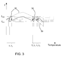
- Figure 3 shows an example of the drift of an oscillator frequency over temperature.
- Plot 30 is the temperature response with no temperature compensation.
- the average frequency is in the allowed frequency range between f min and f max . However, at certain temperatures the frequency leaves the allowed range.
- the invention makes use of the digitally trimming of the oscillator to provide temperature compensation.
- Figure 3 gives one example of how the frequency can be adjusted in dependence of the temperature.
- the controller 28 is adapted to select a trimming setting which has a value which varies at predetermined temperature thresholds T 1 to T 6 .
- the trimming settings have hysteresis such that there are upper temperature thresholds (T 2 ,T 4 ,T 6 ) at which the trimming setting changes in response to an increasing temperature, and lower thresholds (T 1 ,T 3 ,T 5 ) at which the trimming setting changes in response to a decreasing temperature.
- T 1 /T 2 , T 3 /T 4 and T 5 /T 6 represent temperature thresholds with hysteresis.
- the temperature values, as well as the corresponding trimming setting (capacitance and/or resistance) are determined depending on the temperature dependence of the frequency. This example uses three pairs of temperature values, each pair giving a threshold region.
- the required number of thresholds (temperature pairs) can range from 1 to many more than 3.
- the settings of the digital trim values X 01 , X 23 , X 45 and X 67 have to be determined during characterization of the device.
- This invention can be used for any oscillator.
- oscillators that are used to clock the digital logic of a protocol controller.
- one area of interest is in the field of "partial networking"; especially for "CAN" bus systems.
- Partial networking function is for example of interest in the automotive industry.
Abstract
An on-chip RC oscillator comprises a resistor arrangement and a capacitor arrangement at least one of which is tuneable. Trimming settings for the resistor arrangement and/or the capacitor arrangement are stored, and a trimming setting is applied to the resistor arrangement and/or the capacitor arrangement in dependence on a sensed temperature.
Description
- The present invention relates generally to clock circuits and, specifically, to an on-chip RC oscillator that is designed to compensate for temperature variation of the oscillation.
- Microcontrollers are found in wide variety of products, such as electronic consumer devices and household appliances. A microcontroller should be clocked by a stable and accurate oscillating signal.
- One method of generating a stable and accurate clock signal is to use a phase-locked loop (PLL) that receives an accurate reference signal from an external crystal oscillator. Manufacturing costs can be reduced, however, by generating the clock signal using an internal, on-chip oscillator as opposed to a more expensive external crystal oscillator.
- An internal precision oscillator in a microcontroller can be an RC oscillator. A capacitor of the RC circuit is charged and discharged after the voltage across the capacitor reaches a lower and upper trigger voltage, respectively. The rate at which the capacitor is charged and discharged depends on the RC time constant of the RC circuit. The output frequency can be tuned by controlling either the capacitance of the capacitor and/or the resistance of the resistor in the RC circuit.
- One way to perform this tuning is by means of digital control. A number in a register determines a set of capacitors that are switched in parallel, or a resistor configuration that has resistors in series, individual ones of which can be selectively short circuited.
- At the end of production of a device, the oscillator is trimmed close to its target frequency by writing an appropriate number into the register. However, even though the frequency of the oscillator might meet the required target frequency perfectly after programming the register, the frequency might change over temperature and leave the allowed tolerance range.
- In many applications, a microcontroller experiences a wide variation in its operating temperature. Temperature variation can affect the frequency of the clock signal output by the RC oscillator, and that clock signal may become insufficiently stable and not sufficiently accurate for the particular application. For example, the RC oscillator resistor resistance may change with temperature, i.e., the resistor has a positive or negative temperature coefficient. A change in resistance may affect not only the RC time constant, but also the trigger voltages at which the capacitor is charged and discharged.
- In one example, an on-chip oscillator is desired that is capable to clock a CAN (controller area network) controller block. Such CAN controllers require that the clock frequency does not deviate more than a fixed percentage from its nominal frequency. The deviation value depends on the details of the bittiming parameters, but in any case it is less than 2%, in some cases even less than 1%. Since no external clock reference is available, there is currently no design available that meets this requirement over an ambient temperature range from -40°C up to +125°C.
- One method of compensating for resistance changes caused by temperature variation in RC oscillators relies on matching resistors with positive temperature coefficients to resistors having negative temperature coefficients. Transistors and resistors may also be matched in a similar way to provide insensitivity to temperature variations. It can be difficult, however, to manufacture an on-chip resistor/transistor whose temperature coefficient inversely matches that of its paired resistor/transistor over the entire operating temperature range.
-
US 7 176 765 discloses an implementation of temperature compensation by controlling a comparator bias current. - According to the invention, there is provided an on-chip RC oscillator comprising:
- a resistor arrangement and a capacitor arrangement which together define an RC time constant which governs the oscillator frequency, wherein at least one of the resistor arrangement and capacitor arrangement is tuneable,
- a memory for storing trimming settings for the resistor arrangement and/or the capacitor arrangement;
- a temperature sensor; and
- a controller,
- The oscillator of the invention uses the digital trimming arrangement, which can be used in the initial calibration and setting of the device, to implement temperature compensation in use. In this way, little additional hardware is required to implement the invention.
- The resistor arrangement can be fixed, and the capacitor arrangement is then tuneable.
- The controller is preferably adapted to select a trimming setting which has a value which varies at predetermined temperature thresholds. This provides a set of discrete settings, which results in a simpler control method, and avoids the need for large amounts of data to be stored, or complex models to be used to derive the required settings. The resulting frequency is kept within margins by the predetermined temperature threshold values.
- The trimming settings can have hysteresis such that there are upper thresholds at which the trimming setting changes in response to an increasing temperature, and lower thresholds at which the trimming setting changes in response to a decreasing temperature. In this way, the frequency is stable at the temperatures where the trimming settings change, and rapid toggling of the output frequency is avoided.
- The invention also provides a method of controlling the output frequency of an on-chip RC oscillator, wherein the oscillator comprises a resistor arrangement and a capacitor arrangement which together define an RC time constant which governs the oscillator frequency, wherein at least one of the resistor arrangement and capacitor arrangement is tuneable, wherein the method comprises:
- storing trimming settings for the resistor arrangement and/or the capacitor arrangement;
- sensing the temperature; and
- applying a trimming setting to the resistor arrangement and/or the capacitor arrangement in dependence on the sensed temperature.
- The invention will now be described with reference to the accompanying drawings, in which:
-
Figure 1 shows a known RC oscillator; -
Figure 2 shows an oscillator of the invention; and -
Figure 3 is used to explain the control method of the invention. - The invention provides an on-chip RC oscillator in which one or both of a resistor arrangement and a capacitor arrangement of the RC circuit are tuneable. A trimming setting is applied during operation of the oscillator to the tuneable resistor arrangement and/or the capacitor arrangement in dependence on a sensed temperature.
- There are various different types of RC oscillator to which the invention can be applied.
- One example is shown in
Figure 1 , and is described inUS 7 176 765 . - The oscillator 10 has an RC circuit 11, and an RS latch 12 for switching between the output of two
comparators input lead 14 of adischarge comparator 15 and to a non-inverting input lead 16 of acharge comparator 17. - Charge
comparator 17 detects when the voltage on RC node 13 reaches a lower reference voltage, at which time RS latch 12 causes charge to accumulate on RC node 13.Discharge comparator 15 detects when the voltage on RC node 13 reaches a higher reference voltage, at which time RS latch 12 causes charge to discharge from RC node 13. The reference voltages are generated by a voltage divider 18 formed by a resistor string. - As the operating temperature of oscillator 10 changes, the resistance of the resistors in the resistor string change, thereby changing the reference voltages.
- Other designs of RC oscillator do not use comparators in this way. For example, the resistor can be part of a current generator circuit, which determines the rate at which the capacitor is charged. When the capacitor is charged to a given voltage (sufficient to latch the output of a logic device), a shorting transistor is operated to discharge the capacitor. In this way, there is only one reference voltage level.
- Other RC oscillator circuit will be known to those skilled in the art. The invention applies equally to all such designs, as long as the resistance and capacitance together govern the oscillator operating frequency.
-
Figure 2 shows the oscillator of the invention. - The
RC oscillator 20 can be of any suitable known design, providing it has a digitally tuneable capacitor orresistor arrangement 22 as well as theother oscillator circuitry 24. - A tuneable resistor arrangement can comprise a string of resistors in series, with a respective shorting transistor in parallel with each resistor in the string (or only a sub-set of the resistors may need to be shortable). The gate voltages of the shorting transistors are controlled so that they function as binary switches.
- A tuneable capacitor arrangement can comprise an array of capacitors in parallel, with a respective transistor in series with each capacitor in the array (or only a sub-set of the capacitors may need to be switchable into circuit). The gate voltages of the shorting transistors are controlled so that they again function as binary switches.
- The trimmable capacitor or resistor arrangement is shown schematically as 22.
- A
memory 26 stores trimming settings for the resistor arrangement and/or the capacitor arrangement. The ambient temperature is measured by atemperature sensor 27. This is for measuring large scale temperature variations within the operating range of the oscillator. As such, it does not need to be highly sensitive or accurate, and temperature sensors suitable for this purpose are well known, and may be integrated on-chip. - A
controller 28 applies a trimming setting to the resistor arrangement and/or the capacitor arrangement in dependence on the sensed temperature. -
Figure 3 shows an example of the drift of an oscillator frequency over temperature. -
Plot 30 is the temperature response with no temperature compensation. The average frequency is in the allowed frequency range between fmin and fmax. However, at certain temperatures the frequency leaves the allowed range. - The invention makes use of the digitally trimming of the oscillator to provide temperature compensation.
-
Figure 3 gives one example of how the frequency can be adjusted in dependence of the temperature. - The
controller 28 is adapted to select a trimming setting which has a value which varies at predetermined temperature thresholds T1 to T6. - The trimming settings have hysteresis such that there are upper temperature thresholds (T2,T4,T6) at which the trimming setting changes in response to an increasing temperature, and lower thresholds (T1,T3,T5) at which the trimming setting changes in response to a decreasing temperature.
- In the example of
Figure 3 : - If the temperate increases above T2 the digital trim is changed to a fixed value X23.
- If the temperate increases above T4 the digital trim is changed to a fixed value X45.
- If the temperate increases above T6 the digital trim is changed to a fixed value X67.
- If the temperate decreases below T5 the digital trim is changed to a fixed value X45.
- If the temperate decreases below T3 the digital trim is changed to a fixed value X23.
- If the temperate decreases below T1 the digital trim is changed to a fixed value X01.
- The values for T1/T2, T3/T4 and T5/T6 represent temperature thresholds with hysteresis.
- The temperature values, as well as the corresponding trimming setting (capacitance and/or resistance) are determined depending on the temperature dependence of the frequency. This example uses three pairs of temperature values, each pair giving a threshold region. The required number of thresholds (temperature pairs) can range from 1 to many more than 3.
- The settings of the digital trim values X01, X23, X45 and X67 have to be determined during characterization of the device.
- The fact that the frequency is digitally controlled allows an almost perfect compensation of the temperature drift.
- This invention can be used for any oscillator. Of particular interest is oscillators that are used to clock the digital logic of a protocol controller. For example, one area of interest is in the field of "partial networking"; especially for "CAN" bus systems.
- Partial networking function is for example of interest in the automotive industry.
- Various modifications will be apparent to those skilled in the art.
Claims (10)
- An on-chip RC oscillator comprising:a resistor arrangement and a capacitor arrangement (22) which together define an RC time constant which governs the oscillator frequency, wherein at least one of the resistor arrangement and capacitor arrangement is tuneable,a memory (26) for storing trimming settings for the resistor arrangement and/or the capacitor arrangement;a temperature sensor (27); anda controller (28),wherein the controller is adapted to apply a trimming setting to the resistor arrangement and/or the capacitor arrangement in dependence on the sensed temperature.
- An oscillator as claimed in claim 1, wherein the resistor arrangement is fixed and the capacitor arrangement is tuneable.
- An oscillator as claimed in claim 1, wherein the resistor arrangement is tuneable and the capacitor arrangement is fixed.
- An oscillator as claimed in any preceding claim, wherein the controller (28) is adapted to select a trimming setting which has a value which varies at predetermined temperature thresholds (T1 - T6).
- An oscillator as claimed in claim 4, wherein the trimming settings have hysteresis such that there are upper thresholds (T2,T4,T6) at which the trimming setting changes in response to an increasing temperature, and lower thresholds (T1,T3,T5) at which the trimming setting changes in response to a decreasing temperature.
- A method of controlling the output frequency of an on-chip RC oscillator, wherein the oscillator comprises a resistor arrangement and a capacitor arrangement (22) which together define an RC time constant which governs the oscillator frequency, wherein at least one of the resistor arrangement and capacitor arrangement is tuneable, wherein the method comprises:storing trimming settings for the resistor arrangement and/or the capacitor arrangement;sensing the temperature; andapplying a trimming setting to the resistor arrangement and/or the capacitor arrangement in dependence on the sensed temperature.
- A method as claimed in claim 5, wherein the resistor arrangement is fixed and the capacitor arrangement is tuneable.
- A method as claimed in claim 5, wherein the resistor arrangement is tuneable and the capacitor arrangement is fixed.
- A method as claimed in any one of claims 6 to 8, comprising selecting a trimming setting which has a value which varies at predetermined temperature thresholds (T1-T6).
- A method as claimed in claim9, wherein the trimming settings have hysteresis such that there are upper thresholds (T2,T4,T6) at which the trimming setting changes in response to an increasing temperature, and lower thresholds at (T1,T3,T5) which the trimming setting changes in response to a decreasing temperature.
Priority Applications (1)
| Application Number | Priority Date | Filing Date | Title |
|---|---|---|---|
| EP10186725A EP2439846A1 (en) | 2010-10-06 | 2010-10-06 | Temperature compensated RC oscillator |
Applications Claiming Priority (1)
| Application Number | Priority Date | Filing Date | Title |
|---|---|---|---|
| EP10186725A EP2439846A1 (en) | 2010-10-06 | 2010-10-06 | Temperature compensated RC oscillator |
Publications (1)
| Publication Number | Publication Date |
|---|---|
| EP2439846A1 true EP2439846A1 (en) | 2012-04-11 |
Family
ID=43608260
Family Applications (1)
| Application Number | Title | Priority Date | Filing Date |
|---|---|---|---|
| EP10186725A Withdrawn EP2439846A1 (en) | 2010-10-06 | 2010-10-06 | Temperature compensated RC oscillator |
Country Status (1)
| Country | Link |
|---|---|
| EP (1) | EP2439846A1 (en) |
Cited By (3)
| Publication number | Priority date | Publication date | Assignee | Title |
|---|---|---|---|---|
| DE102013225199A1 (en) * | 2013-12-06 | 2015-06-11 | Continental Teves Ag & Co. Ohg | Method for improving the synchronization capability of a data bus transceiver to incoming data bus signals and data bus transceiver |
| US10153773B2 (en) | 2013-12-24 | 2018-12-11 | Nordic Semiconductor Asa | Low-power oscillator |
| CN111404484A (en) * | 2020-04-26 | 2020-07-10 | 珠海迈巨微电子有限责任公司 | RC oscillator and electric device |
Citations (6)
| Publication number | Priority date | Publication date | Assignee | Title |
|---|---|---|---|---|
| US20030231021A1 (en) * | 2002-06-12 | 2003-12-18 | Milad Alwardi | Dynamic trimming technique for variations in oscillator parameters |
| US20060197696A1 (en) * | 2001-08-15 | 2006-09-07 | Norman Robert D | Ring oscillator dynamic adjustments for auto calibration |
| US7176765B1 (en) | 2004-12-31 | 2007-02-13 | Zilog, Inc. | Programmable temperature-compensated RC oscillator |
| US20070241833A1 (en) * | 2006-03-31 | 2007-10-18 | Silicon Laboratories Inc. | Precision oscillator having improved temperature coefficient control |
| US20070241831A1 (en) * | 2004-11-29 | 2007-10-18 | Fred Mirow | Supply voltage controlled voltage and temperature compensated oscillator |
| US20080180298A1 (en) * | 2007-01-29 | 2008-07-31 | Yong Lim | Single slope analog to digital converter using hysteresis property and analog to digital converting method |
-
2010
- 2010-10-06 EP EP10186725A patent/EP2439846A1/en not_active Withdrawn
Patent Citations (6)
| Publication number | Priority date | Publication date | Assignee | Title |
|---|---|---|---|---|
| US20060197696A1 (en) * | 2001-08-15 | 2006-09-07 | Norman Robert D | Ring oscillator dynamic adjustments for auto calibration |
| US20030231021A1 (en) * | 2002-06-12 | 2003-12-18 | Milad Alwardi | Dynamic trimming technique for variations in oscillator parameters |
| US20070241831A1 (en) * | 2004-11-29 | 2007-10-18 | Fred Mirow | Supply voltage controlled voltage and temperature compensated oscillator |
| US7176765B1 (en) | 2004-12-31 | 2007-02-13 | Zilog, Inc. | Programmable temperature-compensated RC oscillator |
| US20070241833A1 (en) * | 2006-03-31 | 2007-10-18 | Silicon Laboratories Inc. | Precision oscillator having improved temperature coefficient control |
| US20080180298A1 (en) * | 2007-01-29 | 2008-07-31 | Yong Lim | Single slope analog to digital converter using hysteresis property and analog to digital converting method |
Non-Patent Citations (1)
| Title |
|---|
| "High Speed 8-Bit TTL A/D Converter AD9012, REV. D", 1999, MA, U.S.A., pages 1 - 8, XP002626186, Retrieved from the Internet <URL:http://www.datasheetarchive.com/pdf/getfile.php?dir=Datasheets-4&file=DSA-73101.pdf&scan=> [retrieved on 20110303] * |
Cited By (3)
| Publication number | Priority date | Publication date | Assignee | Title |
|---|---|---|---|---|
| DE102013225199A1 (en) * | 2013-12-06 | 2015-06-11 | Continental Teves Ag & Co. Ohg | Method for improving the synchronization capability of a data bus transceiver to incoming data bus signals and data bus transceiver |
| US10153773B2 (en) | 2013-12-24 | 2018-12-11 | Nordic Semiconductor Asa | Low-power oscillator |
| CN111404484A (en) * | 2020-04-26 | 2020-07-10 | 珠海迈巨微电子有限责任公司 | RC oscillator and electric device |
Similar Documents
| Publication | Publication Date | Title |
|---|---|---|
| US9746870B2 (en) | Semiconductor device including a constant voltage generation unit | |
| EP1576731B1 (en) | Temperature compensated r-c oscillator | |
| US10254176B2 (en) | Strain-insensitive temperature sensor | |
| US9099994B2 (en) | Relaxation oscillator | |
| CN107040243B (en) | Low-frequency precision oscillator | |
| US8264294B2 (en) | Semiconductor device having on-chip oscillator for producing clock signal | |
| EP3435549B1 (en) | Oscillator calibration system | |
| WO2007101178A2 (en) | Reference-less clock circuit | |
| KR100633361B1 (en) | Tuning circuit | |
| US11949417B2 (en) | Precision oscillators that use imprecise components | |
| EP2439846A1 (en) | Temperature compensated RC oscillator | |
| US7411381B2 (en) | Circuit calibration using a time constant | |
| CN110068401B (en) | Temperature sensing device and temperature-voltage converter | |
| CN104054262B (en) | Cr oscillating circuit | |
| EP2442480A1 (en) | Communications device with adaptive clock frequency | |
| JP2008311884A (en) | Oscillation frequency control method, and oscillator | |
| US7071711B2 (en) | Method and device for determining the ratio between an RC time constant in an integrated circuit and a set value | |
| EP2887545A1 (en) | Oscillator circuit | |
| JP2011103564A (en) | Temperature-compensated piezoelectric oscillator, and method of adjusting frequency for the same | |
| KR102610822B1 (en) | Circuit for controlling oscillator and apparatus including the same | |
| US20140176233A1 (en) | Bandwidth Calibration for Filters | |
| CN113131868B (en) | Digitally regulated oscillator | |
| US8717109B2 (en) | Temperature invariant circuit and method thereof | |
| US10554208B2 (en) | Electronic circuit, semiconductor integrated circuit and monitoring circuit mounted with the same, and electronic device | |
| JP2011103636A (en) | Method of adjusting frequency of temperature-compensated piezoelectric oscillator |
Legal Events
| Date | Code | Title | Description |
|---|---|---|---|
| AK | Designated contracting states |
Kind code of ref document: A1 Designated state(s): AL AT BE BG CH CY CZ DE DK EE ES FI FR GB GR HR HU IE IS IT LI LT LU LV MC MK MT NL NO PL PT RO RS SE SI SK SM TR |
|
| AX | Request for extension of the european patent |
Extension state: BA ME |
|
| PUAI | Public reference made under article 153(3) epc to a published international application that has entered the european phase |
Free format text: ORIGINAL CODE: 0009012 |
|
| STAA | Information on the status of an ep patent application or granted ep patent |
Free format text: STATUS: THE APPLICATION IS DEEMED TO BE WITHDRAWN |
|
| 18D | Application deemed to be withdrawn |
Effective date: 20121012 |