EP2434205A2 - Modular infrared lamp for an infrared vision device of a motor vehicle - Google Patents
Modular infrared lamp for an infrared vision device of a motor vehicle Download PDFInfo
- Publication number
- EP2434205A2 EP2434205A2 EP11180656A EP11180656A EP2434205A2 EP 2434205 A2 EP2434205 A2 EP 2434205A2 EP 11180656 A EP11180656 A EP 11180656A EP 11180656 A EP11180656 A EP 11180656A EP 2434205 A2 EP2434205 A2 EP 2434205A2
- Authority
- EP
- European Patent Office
- Prior art keywords
- infrared
- light
- infrared radiation
- infrared radiator
- semiconductor
- Prior art date
- Legal status (The legal status is an assumption and is not a legal conclusion. Google has not performed a legal analysis and makes no representation as to the accuracy of the status listed.)
- Withdrawn
Links
Images


Classifications
-
- B—PERFORMING OPERATIONS; TRANSPORTING
- B60—VEHICLES IN GENERAL
- B60Q—ARRANGEMENT OF SIGNALLING OR LIGHTING DEVICES, THE MOUNTING OR SUPPORTING THEREOF OR CIRCUITS THEREFOR, FOR VEHICLES IN GENERAL
- B60Q1/00—Arrangement of optical signalling or lighting devices, the mounting or supporting thereof or circuits therefor
- B60Q1/0029—Spatial arrangement
- B60Q1/0041—Spatial arrangement of several lamps in relation to each other
-
- F—MECHANICAL ENGINEERING; LIGHTING; HEATING; WEAPONS; BLASTING
- F21—LIGHTING
- F21S—NON-PORTABLE LIGHTING DEVICES; SYSTEMS THEREOF; VEHICLE LIGHTING DEVICES SPECIALLY ADAPTED FOR VEHICLE EXTERIORS
- F21S41/00—Illuminating devices specially adapted for vehicle exteriors, e.g. headlamps
- F21S41/10—Illuminating devices specially adapted for vehicle exteriors, e.g. headlamps characterised by the light source
- F21S41/12—Illuminating devices specially adapted for vehicle exteriors, e.g. headlamps characterised by the light source characterised by the type of emitted light
- F21S41/13—Ultraviolet light; Infrared light
-
- F—MECHANICAL ENGINEERING; LIGHTING; HEATING; WEAPONS; BLASTING
- F21—LIGHTING
- F21S—NON-PORTABLE LIGHTING DEVICES; SYSTEMS THEREOF; VEHICLE LIGHTING DEVICES SPECIALLY ADAPTED FOR VEHICLE EXTERIORS
- F21S41/00—Illuminating devices specially adapted for vehicle exteriors, e.g. headlamps
- F21S41/10—Illuminating devices specially adapted for vehicle exteriors, e.g. headlamps characterised by the light source
- F21S41/14—Illuminating devices specially adapted for vehicle exteriors, e.g. headlamps characterised by the light source characterised by the type of light source
- F21S41/141—Light emitting diodes [LED]
- F21S41/143—Light emitting diodes [LED] the main emission direction of the LED being parallel to the optical axis of the illuminating device
-
- F—MECHANICAL ENGINEERING; LIGHTING; HEATING; WEAPONS; BLASTING
- F21—LIGHTING
- F21S—NON-PORTABLE LIGHTING DEVICES; SYSTEMS THEREOF; VEHICLE LIGHTING DEVICES SPECIALLY ADAPTED FOR VEHICLE EXTERIORS
- F21S41/00—Illuminating devices specially adapted for vehicle exteriors, e.g. headlamps
- F21S41/10—Illuminating devices specially adapted for vehicle exteriors, e.g. headlamps characterised by the light source
- F21S41/14—Illuminating devices specially adapted for vehicle exteriors, e.g. headlamps characterised by the light source characterised by the type of light source
- F21S41/141—Light emitting diodes [LED]
- F21S41/147—Light emitting diodes [LED] the main emission direction of the LED being angled to the optical axis of the illuminating device
- F21S41/148—Light emitting diodes [LED] the main emission direction of the LED being angled to the optical axis of the illuminating device the main emission direction of the LED being perpendicular to the optical axis
-
- F—MECHANICAL ENGINEERING; LIGHTING; HEATING; WEAPONS; BLASTING
- F21—LIGHTING
- F21S—NON-PORTABLE LIGHTING DEVICES; SYSTEMS THEREOF; VEHICLE LIGHTING DEVICES SPECIALLY ADAPTED FOR VEHICLE EXTERIORS
- F21S41/00—Illuminating devices specially adapted for vehicle exteriors, e.g. headlamps
- F21S41/10—Illuminating devices specially adapted for vehicle exteriors, e.g. headlamps characterised by the light source
- F21S41/14—Illuminating devices specially adapted for vehicle exteriors, e.g. headlamps characterised by the light source characterised by the type of light source
- F21S41/141—Light emitting diodes [LED]
- F21S41/151—Light emitting diodes [LED] arranged in one or more lines
-
- F—MECHANICAL ENGINEERING; LIGHTING; HEATING; WEAPONS; BLASTING
- F21—LIGHTING
- F21S—NON-PORTABLE LIGHTING DEVICES; SYSTEMS THEREOF; VEHICLE LIGHTING DEVICES SPECIALLY ADAPTED FOR VEHICLE EXTERIORS
- F21S41/00—Illuminating devices specially adapted for vehicle exteriors, e.g. headlamps
- F21S41/10—Illuminating devices specially adapted for vehicle exteriors, e.g. headlamps characterised by the light source
- F21S41/19—Attachment of light sources or lamp holders
Definitions
- the present invention relates to an infrared radiator according to the preamble of claim 1.
- Such an infrared radiator is from the DE 10 2007 026 780 A1 known and used to illuminate the spatial apron of the motor vehicle with a high beam characteristic. Since the human eye is not sensitive to infrared radiation, dazzling of oncoming traffic is thereby avoided.
- infrared viewing devices have at least one detector sensitive to infrared radiation, signal processing and a visualization device which images the radiation distribution recorded by the detector in the infrared wavelength range and processed by the signal processing as an image of the illuminated motor vehicle apron visible to the human eye.
- the detector is a camera and is the means of visualization for example a liquid crystal display.
- the radiation spectrum of a radiation source used for active infrared viewing devices in particular comprises wavelengths in the range of near infrared radiation (about 800 nm to 2500 nm).
- infrared radiators were used earlier, which work with a combination of an elliptical reflector, a glass lens, a halogen lamp as a light source and an optical edge filter.
- the filter allows only the infrared portion of the light emitted by the lamp over a wide range of the spectrum to pass through and blocks the remaining visible portion. The efficiency of such systems is rather low.
- infrared emitters based on semiconductors are increasingly being found.
- the infrared radiation emitting light source of such an infrared radiator consists of an array arrangement of individual LED chips whose emitted radiation is concentrated in comparison to the previously described halogen radiator on a narrow spectral range in the vicinity of the visible spectrum.
- the emitted infrared radiation is absorbed by a reflector, which generates the desired radiation distribution on the road. The efficiency is greater compared to the halogen spotlight.
- the aforementioned DE 10 2007 026 780 A1 shows an example of such an infrared radiator.
- the radiation-emitting surface with, for example, about 2 x 5mm 2 is relatively large, ie for a realistic radiation distribution is required reflectors one for LED as a semiconductor infrared radiation sources relatively large focal length and resulting in relatively large dimensions.
- resulting from the concentration of multiple chips in a small space in the array arrangement disadvantages for the thermal management, ie for the maintenance of a comparatively narrow operating temperature window, which in semiconductor infrared radiation sources of great importance for the color stability and the radiation intensity of the emitted light and for the Lifespan is.
- the object of the invention in the specification of an infrared radiator of the type mentioned, which can be adapted with reduced effort to the installation situation in motor vehicles, especially in motor vehicle headlights, and facilitates the thermal management.
- the infrared radiator according to the invention is characterized in that it has at least two modules, of which each individual module has at least one semiconductor infrared radiation source and one light of the semiconductor infrared radiation source comprising distributing optical device.
- at least n optical devices are provided for n semiconductor infrared radiation sources, each of which is assigned to exactly one semiconductor infrared radiation source.
- more than one optical device may be associated with a single semiconductor infrared radiation source, for example a reflector and a lens.
- An infrared radiator according to the invention consists of several individual systems which in their entirety produce the required infrared radiation distribution.
- the individual systems may be configured as a reflection system, imaging projection system (i.e., virtual intermediate image), or as a direct imaging system. A combination of the individual embodiments is possible.
- a pure reflection system consists for example of several chambers, each focal point of which is a single semiconductor infrared radiation source in the form of an infrared light emitting diode.
- a semiconductor component for generating radiation is preferably used to increase the optical efficiency.
- a plurality of semiconductor components LED chips are installed in a common LED housing. Because of the distribution of the total number of semiconductor infrared radiation sources to a plurality of modules, the essential advantages of the invention are retained even in this embodiment.
- the emitted from the individual reflector chambers infrared beams then form in the sum of those for the human eye invisible overall radiation distribution, with which the roadway is illuminated.
- Each module is in itself smaller than the known monolithic and thus integrally constructed infrared radiator.
- the same power spectrum, in particular the same radiation distribution can be generated as with a single, monolithically contiguous and therefore correspondingly large infrared radiator.
- the smaller modules therefore provide, in particular, the same lighting functionality as the monolithic infrared radiator.
- they are much easier to accommodate by a distribution to several smaller installation spaces in a headlight as a large infrared radiator.
- the arrangement of the individual modules in the headlamp can be chosen relatively freely due to their relatively small size.
- the lighting function is modular and scalable, i. the number and arrangement of the individual modules in the headlight can be chosen relatively freely.
- an infrared radiation source is disclosed, which is scalable in its performance and at the same time can be better fitted into a given installation space.
- the modular design and distribution of the modules over an overall larger space results in a greater distance between the semiconductor infrared radiation sources, which facilitates thermal management.
- the relief also arises from the fact that the modular distributed system can be cooled more effectively and, in addition, from the fact that even semiconductor IR radiation sources show a clearer reduction in emitting radiation flux at higher temperatures than e.g. white LEDs.
- the improved heat dissipation allows operation at a mean lower temperature at which a larger radiation flux is emitted than at a higher temperature.
- an infrared radiator for use in a motor vehicle for illuminating the roadway with infrared radiation, which has at least two modules, each of these modules has its own semiconductor infrared radiation source.
- the semiconductor infrared radiation source preferably consists of an LED chip in order to achieve the best possible optical efficiency and essentially emits infrared radiation.
- the individual modules can be embodied as a reflection system, as an imaging projection system or as a direct imaging projection system.
- the whole Radiation distribution is generated by the combination of several separate modules, which may be the same or different.
- the individual modules of such an infrared radiator can each differ in their individually generated radiation distribution, so as to obtain a total of optimized radiation distribution by optimizing the individual modules.
- the modules can also be scalable. Scalability is understood here to mean that the sum of several modules generates a radiation distribution similar to that of a single module, but the intensity within the radiation distributions generated in each case scales with the number of modules used. All in all, this indicates an infrared radiation source which, due to its modular and scalable character, is easier to incorporate into given installation spaces and at the same time can be cooled more efficiently, whereby additionally more IR radiation can be provided.
- each semiconductor infrared radiation source has an infrared light-emitting diode chip.
- an optical device of the infrared radiator has a reflector, and the semiconductor infrared radiation source forms a reflection system together with the reflector.
- the reflector is a free-form surface reflector.
- a further preferred embodiment is characterized in that an optical device has a reflector and a projection lens and the optical device forms a projection system together with the semiconductor infrared radiation source.
- the optical device has a projection lens and the projection lens together with the semiconductor infrared radiation source forms a projection system which directly images the semiconductor light source.
- the optical device has a light-refractive optical attachment of light-conducting material.
- the infrared radiator has a plurality of mutually identical modules and / or a plurality of mutually different modules.
- the various modules of the infrared radiator are supplied via a common board with electrical power and / or controlled.
- the common board is a planar board or a stepped, inherently rigid board or a flexible board.
- each module of the infrared radiator has at least one module - individual heat sink, which is thermally coupled to the semiconductor infrared radiation source.
- modules of the infrared radiator each of which emits an infrared radiation
- the common carrier is aligned parallel to a horizontal axis and pivotally mounted around this axis in a lighting device.
- the infrared radiator is a component of a lighting device for a motor vehicle.
- the illumination device is a motor vehicle headlight which additionally has at least one light module for visible light.
- a support on which modules of the infrared radiator, each of which has a semiconductor infrared radiation source emitting infrared radiation and an optical device emitting radiation of the semiconductor infrared radiation source, are mutually fixed is adjustable from a light module for visible light by pivoting.
- the carrier is additionally mechanically coupled to the visible light module and that the infrared heater is pivoted in operation along with the visible light module about a horizontal axis.
- the illumination device is a front light, which additionally has at least one light source fulfilling signal light functions. Furthermore, it is preferred that the illumination device is realized as a separate infrared headlight which has no further visible light sources.
- the shows Fig. 1 an infrared viewer 10 of a road vehicle.
- the infrared viewing device 10 has an infrared radiator 12, which is set up by its installation position and emission direction to illuminate a predetermined area of the surroundings of the road motor vehicle, in particular the apron lying in the direction of travel, with infrared radiation 14.
- the infrared viewer 10 has a detector 16, for example a camera sensitive to infrared radiation, a control and signal processing device 18 and a means 20 for visualization, for example a liquid crystal display.
- the detector 16 is set up by its installation direction and by its spatial detection range (field of view) and by its matched to the frequency of the infrared radiation 14 spectral sensitivity to infrared radiation 14, which is reflected by objects in the infrared radiation 14 illuminated area of the motor vehicle environment record and into signals, in particular electrical signals, which are processed by the control and signal processing device 18 and converted into drive signals for the means 20 for visualization.
- the conversion takes place in such a way that the means 20 visualizes the region of the surroundings of the motor vehicle illuminated by infrared radiation 14 in a manner perceptible to the human eye, for example by means of a picture on a screen of the device 20.
- the control and signal processing device 18 is preferably configured to control the operation of the infrared radiator 12.
- the infrared radiator is operated pulsed so that it emits infrared radiation 14 in comparatively short transmission pulses, these short transmission pulses being separated from one another by comparatively longer transmission pauses. This reduces in particular the risk of dazzling an infrared viewing device of an oncoming vehicle. Detection by the detector is synchronous with the transmit pulses. Another advantage of pulsed operation is that lock-in amplification of the detected signals is possible.
- the signals of the detector 16 obtained during the transmission pulses from the control and signal processing device 18 form the basis for the imaging of the vehicle apron by the means 20.
- the control and signal processing device 18 determines in one embodiment from signals of the detector 16 values of the background radiation emanating from the environment, such as street lights, and takes into account the results of this background measurement in the control of the means 20 for visualization.
- the connections 22.1 to 22.n and 24, 26 are realized in a preferred embodiment in the form of a bus system, wherein preferably further control devices, sensors and actuators are connected to the bus system.
- the infrared radiator 12 can also be used multiple times, for example, by the fact that its signals are also used for distance measurements in stop-and-go traffic and / or for automatic parking.
- the present invention is characterized in that the infrared radiator 12 has at least two modules 28 and 30, each of which has at least one semiconductor infrared radiation source and optical device distributing light 14 to the respective semiconductor infrared radiation source.
- a first module 28 in particular a semiconductor infrared radiation source 32 and an infrared radiation of the semiconductor infrared radiation source 32 distributing optical Device 34.
- the second module 30 comprises a second semiconductor infrared radiation source 36 and a second light 14 of the second semiconductor infrared radiation source 36 distributing optical device 38.
- the dotted line on the right of the two modules 28 and 30 indicates that embodiments of infrared radiators 12 according to the invention can also have more than two modules.
- the number of modules can therefore, depending on the embodiment, be equal to n, where n is a number ⁇ 2.
- n is a number ⁇ 2.
- the optical devices 34 and 38 are in the Fig. 1 represented in the form of reflectors. However, as far as in this application of optical devices with the reference numerals 34 and 38 in this general form is mentioned, it should not only Reflectors, but also all other means are meant that are suitable for the distribution of infrared radiation. Embodiments of such means are given below.
- a distribution of the infrared radiation is not understood to mean any scattering of the infrared light, but rather a targeted redirection of the infrared radiation emanating from the respective semiconductor infrared radiation source 32, 36 of the participating modules 28, 30 (and possibly further modules) into a desired and / or or prescribed illumination intensity pattern in the area to be illuminated of the environment of the motor vehicle.
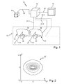
- FIG. 2 shows lines of equal illumination intensity in a plane that is from a Horizontal H and a vertical V is spanned.
- the horizontal H is parallel to a transverse axis of the road vehicle and the vertical V is parallel to a vertical axis of the motor vehicle.
- the numerical values are angular degrees.
- the value pair (0, 0) lies on the extension of a longitudinal axis of a lighting device in which the infrared radiator is installed.
- the intensity is constant along a line and increases from outside to inside. With respect to the values of their intensity, any adjacent lines have the same distance.
- the radiation distribution shown as an example along the horizontal H is about 16 ° wide and extends in the vertical about 12 degrees. By this compared to their height slightly larger width, the illumination of the lateral edge regions of the field of view of the infrared viewer 10 is improved at the expense of other areas of illumination. It is also evident that in the Fig. 2 shown infrared radiation distribution 42 a high-beam characteristic, that is, a characteristic without right / left asymmetry and in particular without an asymmetric light-dark boundary, as is common in the low beam in the visible range has.
- the Fig. 3 shows a single such module 28 having a semiconductor infrared radiation source 32 and a reflector 44 as a light-distributing optical device 34.
- the reflector 44 in a preferred embodiment has a parabolic basic shape with a focal point in which the light exit surface of the semiconductor infrared radiation source 32 is arranged.
- the semiconductor infrared radiation source 32 is an infrared light-emitting diode 48, which is cohesively arranged on a mounting support 46 and has a light exit surface of the order of magnitude of 1 mm 2 .
- Infrared light-emitting diodes are known as such and have, for example, gallium arsenide (GaAs) or aluminum gallium arsenide (AlGaAs) as semiconductor material.
- GaAs gallium arsenide
- AlGaAs aluminum gallium arsenide
- the cohesive connection of the substrate of the infrared light-emitting diode takes place for example by gluing.
- the reflector 44 is realized in a preferred embodiment as a so-called free-form reflector.
- a free-form reflector is understood to be a reflector whose reflector surface is specifically shaped such that individual points and / or regions of the reflector surface are arranged and aligned in such a way that they selectively reflect incident light from the focal point into specific areas of the reflector apron, so that the sum of all contributions of individual reflector points and / or reflector segments gives the desired radiation distribution.
- the reflector 44 is 40 mm to 50 mm wide and 25 mm to 35 mm high. This example refers to an infrared radiator with five equal modules. Depending on the number of modules used and depending on the radiation power of the semiconductor infrared radiation source used in a module, other dimensions may also prove advantageous.
- the Fig. 3 shows in particular a module 28 whose optical device 34 has a reflector 44 which forms a reflection system with its associated semiconductor infrared radiation source 32.
- a reflection system is understood as a system in which the desired radiation distribution is effected by the reflector 44.
- An infrared radiator constructed of such modules consists of a plurality of single-chip infrared-emitting LEDs each positioned at the focal point of a parabolic-based reflector chamber (i.e., the space bulged by the reflector). The radiation emitted by the individual LEDs is collected by the reflectors and directed in the direction of travel.
- the radiation beams emitted by the individual reflector chambers then form, in the sum, the total radiation distribution which is invisible to the human eye and with which the roadway is illuminated.
- the reflectors can be designed as free-form surfaces in order to make the shape of the radiation distribution in their scattering and scattering height free.
- the Fig. 4 shows an alternative embodiment of a module 28, in which the optical device 34 a Reflector 50 and a projection lens 52 has.
- the reflector 50 is preferably a free-form reflector, which is designed such that it generates a desired radiation distribution from the light of a semiconductor infrared radiation source 32 in cooperation with the projection lens 52.
- the reflector 50 preferably has an ellipsoidal basic shape.
- the semiconductor infrared radiation source 32 is preferably arranged in a first focal point F1 of the reflector, so that the reflector 50 bundles the light emanating from the semiconductor infrared radiation source 32 in a second focal point F2.
- the second focus thus effectively forms a virtual light source from which a divergent beam 54 emanates.
- This divergent beam is projected by the projection lens 52 in the apron in front of the module 28 and thus in the apron of the infrared radiator 12.
- the optical properties of the reflector 50 and the projection lens 52 and their geometric arrangement relative to one another are coordinated with one another in such a way that the desired radiation distribution in advance of the module 28 is established in cooperation.
- the projection lens is preferably made of glass or a transparent plastic.
- the Fig. 4 shows in particular an optical device 34 having a reflector 50 and a projection lens 52, wherein the optical device 34 together with the semiconductor infrared radiation source 32 forms a projection system.
- the reflectors 44 and 50 must bulge each only in a half-space, since the semiconductor infrared radiation sources emit their entire luminous flux in a cone of light that lies within a half-space.
- the requirement that the reflectors must extend only in a half-space, is in particular from the Fig. 4 clearly, in which the entire reflector surface of the reflector 50 is above an optical axis 56 of the module 28.
- the projection system after the Fig. 4 has opposite the reflection system according to the Fig. 3 the advantage that its height required perpendicular to the optical axis 56 may be lower.
- this advantage is paid for by the fact that the projection system requires a greater installation depth in the direction of the optical axis than the particularly short reflection system in comparison.
- the reflection system requires comparatively less installation depth in the direction of the optical axis, because it does not require a series arrangement of reflector and lens.
- a further embodiment of an infrared radiator 12 is characterized in that the optical device 34 has a projection lens 52 and the projection lens 52 together with the semiconductor infrared radiation source 32 forms a projection system directly imaging the semiconductor infrared radiation source 32.
- Such a direct imaging system requires no transverse to the optical axis extended reflector and therefore has a correspondingly simple and little space-requiring structure.
- the Fig. 5 shows a further embodiment of an optical device 34, which is adapted to light 14 of a semiconductor infrared radiation source 32 to distribute so that a desired radiation distribution in the run-up to the infrared radiator 12 results.
- an optical device 34 which is adapted to light 14 of a semiconductor infrared radiation source 32 to distribute so that a desired radiation distribution in the run-up to the infrared radiator 12 results.
- At the subject of Fig. 5 is close to the light emitting surface of the Infrared light emitting diode 48 of a semiconductor infrared radiation source 32 an infrared radiation refractive and internally possibly totally reflective optical attachment 59 arranged for infrared radiation transparent material.
- the coupled via a light entrance surface 58 of the optical attachment 59 in the optical attachment light of the infrared light emitting diode 48 is deflected either directly or after an on sidewalls 62, 64 of the optical attachment 59 occurring internal total reflection via a light exit surface 60 of the optical attachment 59 in the apron in front of the infrared radiator 12. Internal total reflection takes place in cases in which the angle of incidence of the radiation propagating in the optical attachment to the sidewalls 62, 64 is greater than a critical angle resulting from the refractive indices of the optically denser material of the optical attachment and the air.
- the deflection can be influenced by appropriate design of the totally reflective side walls 62 and 64 and the light-refracting light exit surface 60, which forms an interface between the optically denser material of the optical attachment 59 and the optically thinner air. In one embodiment, these parameters are deliberately predetermined so that a desired radiation distribution is set in advance of the infrared radiator 12.
- the Fig. 5 shows thus in particular an optical device 34 with a light refractive optical attachment 59 of light-conducting material.
- An optical device 34 which has such an attachment optics 59 is characterized by a particularly compact construction.
- the intent optical system 59 is itself so compact that it also with the embodiments of the FIGS. 3 and 4 can be combined.
- An embodiment is therefore characterized by the fact that the reflection system, as shown in the Fig. 3 is shown, in addition, a front optics 59 between the light exit surface of the infrared light emitting diode 48 and the reflector 44 has.
- Another embodiment is characterized in that a projection system, as in the Fig. 4 is shown, in addition, a front optics 59 between the light emitting surface of the associated light emitting diode and the reflector 50 has.
- the attachment optics can also be combined well with a module that has a direct imaging lens.
- the semiconductor infrared radiation source, the front optics and the lens are preferably arranged along the optical axis of the module so that the optical attachment of the semiconductor infrared radiation source directs coupled infrared radiation in a focused form onto the lens.
- the Fig. 6 shows an embodiment of an infrared radiator 12 having a plurality of mutually identical modules 28.1, 30.1, ...
- the modules 28.1, 30.1 each have, for example, an optical device with a reflection system.
- they have an optical device with a projection system or an optical device with a refractive optical attachment or an optical device with refractive optical attachment in combination with a reflection system or in combination with a projection system.
- This embodiment can be produced in particular cost.
- the Fig. 7 shows an alternative embodiment, in which an infrared radiator 12 has a plurality of mutually different modules 28.2, 30.2.
- the module 28.2 In one embodiment, it has an optical device with a reflection system, while the second module 30.2 has an optical device 34 with a projection module. Accordingly, an installation space with a comparatively large height is required for the arrangement of the first module 28.2, but at the same time the requirements for the installation depth are comparatively low. In contrast, for the installation of the second module 30.2 an installation space with a comparatively small height and a but relatively larger installation depth is required.
- This embodiment has over an embodiment with standardized same modules the advantage that a radiation distribution having certain desired properties, easier and better to achieve.
- comparatively large focal length parabolic reflectors are comparatively well suited for producing a narrow and long range fraction of a desired infrared radiation distribution
- relatively short focal length parabolic reflectors are well suited for producing a broader, shorter range portion of the radiation distribution.
- a further embodiment is characterized in that the reflectors serving to produce the broader portion of the radiation distribution having a shorter range have facets in the reflective surface with which the radiation is purposefully distributed more broadly than would be the case without such facets.
- modules with different sized reflector chambers are used to take advantage of space-filling different sized installation spaces that are available within a housing of a lighting device.
- the embodiment with mutually identical modules 28.1, 30.1 has the advantage over a more uniform appearance, which is advantageous from a design point of view, when the infrared radiation emitting surfaces of the infrared radiator are visible from the outside. In addition, it is particularly inexpensive.
- FIG. 5 shows the appearance of a headlamp 66 in which five modules 28, 30, 33, 35, 40 of an infrared radiator 12 are arranged below two light modules 68, 70, which are adapted to realize headlamps and / or headlamp light functions in the visible range such as low beam functions, high beam functions, foglight functions, Daytime running light functions, flashing light functions and marking light functions, although this enumeration is not meant to be exhaustive and the individually enumerated functions are to be understood as examples only.
- the infrared radiator 12 is arranged in an embodiment in a lighting device for a motor vehicle.
- the lighting device is in one embodiment, a headlamp, which also has at least one light module for generating a light distribution such as a low beam distribution and / or a high beam distribution and / or a fog light distribution, this list is not to be understood as exhaustive.
- the infrared radiator 12 is housed in a front light.
- the front light is in one embodiment, a flashing light or a daytime running light lamp, which also applies here, that this list should not be exhaustive.
- Under lights are generally understood lighting devices that serve signaling purposes.
- headlamps are understood to be lighting devices which illuminate the surroundings of the motor vehicle in order to make visible to the driver unilluminated objects which are located in its travel path.
- a further embodiment provides that the infrared radiator is realized in a separate illumination device as a separate infrared headlight.
- the modules 28, 30, 33, 35, 40 of an infrared radiator 12 are arranged in a preferred embodiment on a common frame or support in a lighting device for a motor vehicle.
- the support in the illumination device is preferably arranged such that it can pivot about a horizontal axis, in order to allow adjustment of the illumination range, be it manually or automatically.
- the carrier is pivotable relative to the light modules for visible light to a basic setting of the Infrarotstrahlungsausbreitungsraum relative to the propagation direction of the visible light, in particular to allow the dipped beam.
- An alternative embodiment provides that the modules are mounted individually or in multiple on several separate carriers or frames in the lighting device.
- the attachment is preferably such that the modules are aligned parallel to the vehicle longitudinal axis, so that the infrared radiation to the front pointing preferential direction.
- the modules are individually or jointly pivotable, as is known from conventional low-beam modules and / or high-beam modules. It is particularly preferred that the modules are configured pivotable about a horizontal axis in order to regulate a luminous range of the infrared radiation. In addition, a further embodiment provides pivotability about a vertical axis, as is known from curve light modules, which generate light distributions in the visible light range.
- an embodiment provides that the modules of the infrared radiator are arranged and fixed in a common swing frame with a light module for visible light and pivoted together. Thereby pivoting of the visible light modules and the modules of the infrared radiator are provided with little effort since the same swing frame structures and hinges as well as drive motors, control structures and vehicle tilt sensors can be used for both the pivoting of the visible light beams and the infrared radiation ,
- the Fig. 9 shows various embodiments of infrared radiators 12, which are characterized in that the various modules 28, 30, 33, 35, 40 of the infrared radiator 12, each of which has at least one semiconductor infrared radiation source and radiation of the semiconductor infrared radiation source distributing optical device, be supplied and / or controlled by a common board 72, 74 or 76 with electrical power.
- a flat circuit board or a stepped circuit board can be used to receive and contact the individual LED housings.
- a flat circuit board or a stepped circuit board can be used to receive and contact the individual LED housings.
- the Fig. 9a shows a rigid, planar board 72, while the Fig. 9b a rigid, stepped board 74, and the Fig. 9c a flexible bendable board 76 shows.
- the rigid boards 72, 74 have opposite the flexible board 76th the advantage of greater robustness in the handling of the infrared radiator 12, which, for example, simplifies the manufacture of a headlight 66 with an infrared radiator 12 integrated in the headlight housing.
- rigid boards are cheaper than flexible boards.
- the flexible board has the advantage of better adaptability to curvatures, which has the available installation space.
- the stepped but rigid board 74 is in some ways a compromise between the planar and rigid board 72 and the flexible board 76.
- FIG. 12 shows an embodiment of a semiconductor infrared radiation source 32 adapted to emit infrared radiation 14, together with a circuit board 78 and a heat sink 80.
- the semiconductor infrared radiation source 32 comprises one or more chips 82 of semiconductor material formed by their material Doping are adapted to generate infrared radiation 14.
- the chip or chips 82 are arranged on a substrate or mounting support 84, via which the semiconductor layers are electrically contacted.
- the mounting bracket is mounted on a board 78, which is a rigid and planar board 72, or a rigid and stepped board 74 or a flexible board 76 in the Fig. 9 can be shown. It is preferred that the mounting bracket 84 is thermally coupled through the board from its back with a heat sink 80.
- a board with an integrated heat sink for example in the form of a metal core board can be used.
- the Fig. 11 shows a preferred embodiment of an infrared radiator 12 comprising modules 28, 30, 33, 35, 40, each of which comprises an infrared radiation emitting semiconductor infrared radiation source 92, 94, 96, 98, 100 and a radiation of the semiconductor infrared radiation source 92, 94, 96, 98, 100 distributing optical device 102, 104, 106, 108, 110 has.
- the optical devices in one embodiment are different large reflectors.
- the semiconductor infrared radiation sources 92, 94, 96, 98, 100 are mounted together with their board 78 on a common support 86.
- the common carrier is aligned parallel to a horizontal axis 90 and pivotally mounted about this axis 90 in a lighting device to enable headlamp leveling.
- an adjusting means 88 which is preferably configured as a manually operable adjusting mechanism or as an electrically operated adjustment mechanism.
- a headlamp which in addition to an infrared radiator 12 still has light modules for visible light, in particular low beam or high beam, preferred embodiments provide the following:
- the carrier 86 is adjustable by pivoting, so that the radiation distribution of the infrared radiator 12 can be adjusted at the end of the band in the manufacture of the headlamp relative to the light distribution of the light module for visible light. Thereby, a basic adjustment of the infrared radiation distribution relative to the light distribution for the visible light is generated.
- an embodiment provides that the carrier 86 is additionally mechanically coupled to the light module for visible light that the infrared radiator 12 is pivoted in operation together with the light module for visible light about a horizontal axis.
Landscapes
- Engineering & Computer Science (AREA)
- General Engineering & Computer Science (AREA)
- Physics & Mathematics (AREA)
- Microelectronics & Electronic Packaging (AREA)
- Optics & Photonics (AREA)
- Mechanical Engineering (AREA)
- Non-Portable Lighting Devices Or Systems Thereof (AREA)
- Lighting Device Outwards From Vehicle And Optical Signal (AREA)
- Led Device Packages (AREA)
Abstract
Description
Die vorliegende Erfindung betrifft einen Infrarotstrahler nach dem Oberbegriff des Anspruchs 1. Ein solcher Infrarotstrahler ist aus der
Neben dem Infrarotstrahler weisen Infrarotsichtgeräte wenigstens einen für Infrarotstrahlung empfindlichen Detektor, eine Signalverarbeitung und ein Mittel zur Visualisierung auf, das die vom Detektor im infraroten Wellenlängenbereich aufgenommene und von der Signalverarbeitung verarbeitete Strahlungsverteilung als für das menschliche Auge sichtbares Bild des beleuchteten Kraftfahrzeugvorfeldes abbildet. Der Detektor ist zum Beispiel eine Kamera und das Mittel zu Visualisierung ist zum Beispiel eine Flüssigkristallanzeige. Das Spektrum der Strahlung einer für aktive Infrarotsichtgeräte verwendeten Strahlungsquelle umfasst insbesondere Wellenlängen im Bereich der nahen Infrarotstrahlung (etwa 800 nm bis 2500 nm).In addition to the infrared radiator, infrared viewing devices have at least one detector sensitive to infrared radiation, signal processing and a visualization device which images the radiation distribution recorded by the detector in the infrared wavelength range and processed by the signal processing as an image of the illuminated motor vehicle apron visible to the human eye. For example, the detector is a camera and is the means of visualization for example a liquid crystal display. The radiation spectrum of a radiation source used for active infrared viewing devices in particular comprises wavelengths in the range of near infrared radiation (about 800 nm to 2500 nm).
Als Alternative zu dem eingangs genannten Infrarotstrahler wurden bereits früher Infrarotstrahler verwendet, die mit einer Kombination aus einem elliptischen Reflektor, einer Glaslinse, einer Halogenlampe als Lichtquelle und einem optischen Kantenfilter arbeiten. Das Filter lässt dabei nur den infraroten Anteil des von der Lampe über einen breiten Bereich des Spektrums emittierten Lichtes passieren und blockiert den restlichen sichtbaren Anteil. Die Effizienz solcher Systeme ist eher gering.As an alternative to the infrared radiator mentioned earlier, infrared radiators were used earlier, which work with a combination of an elliptical reflector, a glass lens, a halogen lamp as a light source and an optical edge filter. The filter allows only the infrared portion of the light emitted by the lamp over a wide range of the spectrum to pass through and blocks the remaining visible portion. The efficiency of such systems is rather low.
Darüber hinaus findet man in letzter Zeit immer häufiger Infrarotstrahler auf Halbleiterbasis. Die infrarote Strahlung emittierende Lichtquelle eines solchen Infrarotstrahlers besteht dabei aus einer Array-Anordnung einzelner LED-Chips, deren abgegebene Strahlung im Vergleich zum zuvor beschriebenen Halogenstrahler auf einen schmalen Spektralbereich in der Nähe des sichtbaren Spektrums konzentriert ist. Die abgegebene infrarote Strahlung wird durch einen Reflektor aufgenommen, der die gewünschte Strahlungsverteilung auf der Fahrbahn erzeugt. Die Effizienz ist im Vergleich zum Halogenstrahler größer. Die eingangs genannte
Aufgrund der Array-Anordnung ist die strahlungsemittierende Fläche mit zum Beispiel ca. 2 x 5mm2 relativ groß, d.h. für eine realistische Strahlungsverteilung benötigt man Reflektoren die eine für LED als Halbleiter-Infrarotstrahlungsquellen relativ große Brennweite und daraus resultierende, relativ große Abmessungen aufweisen. Außerdem ergeben sich aus der Konzentration mehrerer Chips auf geringem Raum in der Array-Anordnung Nachteile für das Thermomanagement, also für die Einhaltung eines vergleichsweise engen Betriebstemperaturfensters, was bei Halbleiter-Infrarotstrahlungsquellen von großer Bedeutung für die Farbstabilität und die Strahlungsstärke des ausgesandten Lichtes und für die Lebensdauer ist.Due to the array arrangement, the radiation-emitting surface with, for example, about 2 x 5mm 2 is relatively large, ie for a realistic radiation distribution is required reflectors one for LED as a semiconductor infrared radiation sources relatively large focal length and resulting in relatively large dimensions. In addition, resulting from the concentration of multiple chips in a small space in the array arrangement disadvantages for the thermal management, ie for the maintenance of a comparatively narrow operating temperature window, which in semiconductor infrared radiation sources of great importance for the color stability and the radiation intensity of the emitted light and for the Lifespan is.
Sowohl die mit Halogenlampen als Projektionssystem arbeitenden Infrarotstrahler als auch die bekannten, mit Halbleiter-Infrarotstrahlungsquellen und einem großen Reflektor als Reflexionssystem arbeitenden Infrarotstrahler lassen sich durch ihre großen Abmessungen nur schwer an die unterschiedlichen Einbausituationen verschiedener Automobilscheinwerfer anpassen, da der von ihnen benötigte Bauraum in Form und Größe gar nicht oder nur unter großem konstruktivem und herstellungstechnischen Aufwand veränderbar ist. Dies schränkt die Gestaltungsfreiheit beim Kraftfahrzeugdesign stark ein und/oder es erhöht die für eine Ausrüstung mit einem Infrarotsichtsystem fällig werdenden Kosten aufgrund des genannten großen Aufwandes.Both working with halogen lamps as a projection system infrared radiator and the known, working with semiconductor infrared radiation sources and a large reflector as a reflection system infrared radiator can be difficult to adapt to the different installation situations of various automobile headlights by their large dimensions, since the space required by them in shape and Size is not at all or only with great constructive and manufacturing effort is changeable. This severely restricts the design freedom in automotive design and / or increases the costs due to equipment with an infrared vision system due to the large expense involved.
Vor diesem Hintergrund besteht die Aufgabe der Erfindung in der Angabe eines Infrarotstrahlers der eingangs genannten Art, der sich mit einem verringerten Aufwand an die Einbausituation in Kraftfahrzeugen, insbesondere in Kraftfahrzeugscheinwerfern, anpassen lässt und der das Thermomanagement erleichtert.Against this background, the object of the invention in the specification of an infrared radiator of the type mentioned, which can be adapted with reduced effort to the installation situation in motor vehicles, especially in motor vehicle headlights, and facilitates the thermal management.
Diese Aufgabe wird mit den Merkmalen des Anspruchs 1 gelöst. Der erfindungsgemäße Infrarotstrahler zeichnet sich dadurch aus, dass er wenigstens zwei Module aufweist, von denen jedes einzelne Modul wenigstens eine Halbleiter-Infrarotstrahlungsquelle und eine Licht der Halbleiter-Infrarotstrahlungsquelle verteilende optische Vorrichtung aufweist. Für n Halbleiter-Infrarotstrahlungsquellen sind daher insbesondere wenigstens n optische Vorrichtungen vorgesehen, von denen jede jeweils genau einer Halbleiter-Infrarotstrahlungsquelle zugeordnet ist. Es können aber auch mehr als eine optische Vorrichtung einer einzelnen Halbleiter-Infrarotstrahlungsquelle zugeordnet sein, zum Beispiel ein Reflektor und eine Linse.This object is achieved with the features of claim 1. The infrared radiator according to the invention is characterized in that it has at least two modules, of which each individual module has at least one semiconductor infrared radiation source and one light of the semiconductor infrared radiation source comprising distributing optical device. In particular, at least n optical devices are provided for n semiconductor infrared radiation sources, each of which is assigned to exactly one semiconductor infrared radiation source. However, more than one optical device may be associated with a single semiconductor infrared radiation source, for example a reflector and a lens.
Durch den modularen Aufbau wird der beim Stand der Technik übliche monolithische Aufbau eines Infrarotstrahlers gewissermaßen aufgebrochen. Ein erfindungsgemäßer Infrarotstrahler besteht aus mehreren einzelnen Systemen, die in ihrer Gesamtheit die geforderte Infrarotstrahlungsverteilung erzeugen. Die einzelnen Systeme können als Reflexionssystem, abbildendes Projektionssystem (d.h. mit virtuellem Zwischenbild) oder als direkt abbildendes System ausgestaltet sein. Eine Kombination der einzelnen Ausführungsformen ist möglich.Due to the modular structure of the usual in the prior art monolithic structure of an infrared radiator is broken to a certain extent. An infrared radiator according to the invention consists of several individual systems which in their entirety produce the required infrared radiation distribution. The individual systems may be configured as a reflection system, imaging projection system (i.e., virtual intermediate image), or as a direct imaging system. A combination of the individual embodiments is possible.
Ein reines Reflexionssystem besteht z.B. aus mehreren Kammern, in deren Brennpunkt sich jeweils eine einzelne Halbleiter-Infrarotstrahlungsquelle in Form einer Infrarotleuchtdiode befindet. In der Infrarotleuchtdiode kommt vorzugsweise zur Erhöhung der optischen Effizienz nur ein Halbleiterbaustein zur Strahlungserzeugung zum Einsatz. Zur Steigerung der emittierten Strahlungsleistung pro Modul ist es auch denkbar, dass mehrere Halbleiterbausteine (LED-Chips) in einem gemeinsamen LED-Gehäuse verbaut werden. Wegen der Aufteilung der Gesamtzahl der Halbleiter-Infrarotstrahlungsquellen auf mehrere Module bleiben die wesentlichen Vorteile der Erfindung auch bei dieser Ausgestaltung erhalten. Die von den einzelnen Reflektorkammern abgegebenen infraroten Strahlenbündel bilden dann in der Summe die für das menschliche Auge unsichtbare Gesamtstrahlungsverteilung, mit der die Fahrbahn ausgeleuchtet wird.A pure reflection system consists for example of several chambers, each focal point of which is a single semiconductor infrared radiation source in the form of an infrared light emitting diode. In the infrared light-emitting diode, only a semiconductor component for generating radiation is preferably used to increase the optical efficiency. To increase the emitted radiation power per module, it is also conceivable that a plurality of semiconductor components (LED chips) are installed in a common LED housing. Because of the distribution of the total number of semiconductor infrared radiation sources to a plurality of modules, the essential advantages of the invention are retained even in this embodiment. The emitted from the individual reflector chambers infrared beams then form in the sum of those for the human eye invisible overall radiation distribution, with which the roadway is illuminated.
Jedes Modul ist für sich betrachtet kleiner als der bekannte monolithisch und damit einstückig zusammenhängend aufgebaute Infrarotstrahler. In der Summe über alle Module kann jedoch das gleiche Leistungsspektrum, insbesondere die gleiche Strahlungsverteilung wie mit einem einzelnen, monolithisch zusammenhängenden und damit entsprechend großen Infrarotstrahler erzeugt werden. Die kleineren Module stellen also insbesondere die gleiche Lichtfunktionalität zur Verfügung wie der monolithische Infrarotstrahler. Im Vergleich zu dem bekannten Infrarotstrahler sind sie jedoch durch eine Verteilung auf mehrere kleinere Einbauräume in einem Scheinwerfer wesentlich leichter unterzubringen als ein großer Infrarotstrahler. Dabei lässt sich die Anordnung der einzelnen Module im Scheinwerfer aufgrund ihrer vergleichsweise geringen Größe relativ frei wählen.Each module is in itself smaller than the known monolithic and thus integrally constructed infrared radiator. In the sum of all modules, however, the same power spectrum, in particular the same radiation distribution can be generated as with a single, monolithically contiguous and therefore correspondingly large infrared radiator. The smaller modules therefore provide, in particular, the same lighting functionality as the monolithic infrared radiator. Compared to the known infrared radiator, however, they are much easier to accommodate by a distribution to several smaller installation spaces in a headlight as a large infrared radiator. In this case, the arrangement of the individual modules in the headlamp can be chosen relatively freely due to their relatively small size.
Durch die Aufteilung auf mehrere einzelne Module mit jeweils einer dem Modul zugeordneten Halbleiter-Infrarotstrahlungsquelle ist die lichttechnische Funktion modular und skalierbar, d.h. die Zahl und Anordnung der einzelnen Module im Scheinwerfer lässt sich relativ frei wählen.By dividing it into several individual modules, each with a semiconductor infrared radiation source associated with the module, the lighting function is modular and scalable, i. the number and arrangement of the individual modules in the headlight can be chosen relatively freely.
Durch den modularen Charakter des Systems können unterschiedlich ausgestaltete Module, zum Beispiel Reflektorkammern, zu verschiedenen Bereichen der Strahlungsverteilung beitragen. Die geringere Ausdehnung der einzelnen LED-Chips (ca. 1 mm2) ermöglicht eine kompakte Bauweise der Module mit relativ geringer Ausdehnung.Due to the modular nature of the system, differently designed modules, for example reflector chambers, can contribute to different areas of the radiation distribution. The smaller expansion of the individual LED chips (about 1 mm 2 ) allows a compact design of the modules with relatively low expansion.
Im Ergebnis wird damit eine Infrarotstrahlungsquelle offenbart, die in ihrer Leistung skalierbar ist und die gleichzeitig besser in einen vorgegebenen Bauraum eingepasst werden kann.As a result, an infrared radiation source is disclosed, which is scalable in its performance and at the same time can be better fitted into a given installation space.
Darüber hinaus ergibt sich aus dem modularen Aufbau und der Verteilung der Module auf einen insgesamt größeren Raum eine größere Entfernung zwischen den Halbleiter-Infrarotstrahlungsquellen, was das Thermomanagement erleichtert. Dies ergibt sich daraus, dass die Aufteilung auf einzelne Module eine räumliche Aufteilung der in den Halbleiterchips anfallenden elektrischen Verlustwärme mit sich bringt. Die Erleichterung ergibt sich ferner daraus, dass das modular verteilte System effektiver gekühlt werden kann und zusätzlich daraus, dass gerade Halbleiter-IR-Strahlungsquellen eine deutlichere Verringerung des emittierenden Strahlungsflusses mit höheren Temperaturen zeigen, als z.B. weiße LEDs. Die verbesserte Entwärmung erlaubt einen Betrieb mit einer im Mittel niedrigeren Temperatur, bei der ein größerer Strahlungsfluss emittiert wird als bei einer höheren Temperatur.Moreover, the modular design and distribution of the modules over an overall larger space results in a greater distance between the semiconductor infrared radiation sources, which facilitates thermal management. This results from the fact that the division into individual modules brings about a spatial distribution of the electrical heat losses occurring in the semiconductor chips. The relief also arises from the fact that the modular distributed system can be cooled more effectively and, in addition, from the fact that even semiconductor IR radiation sources show a clearer reduction in emitting radiation flux at higher temperatures than e.g. white LEDs. The improved heat dissipation allows operation at a mean lower temperature at which a larger radiation flux is emitted than at a higher temperature.
Insgesamt stellt der hier vorgestellte Anmeldungsgegenstand einen Infrarotstrahler zum Einsatz in einem Kraftfahrzeug zur Ausleuchtung der Fahrbahn mit Infrarotstrahlung vor, der wenigstens zwei Module aufweist, wobei jedes dieser Module eine eigene Halbleiter-Infrarotstrahlungsquelle besitzt. Die Halbleiter-Infrarotstrahlungsquelle besteht vorzugsweise aus einem LED-Chip um eine bestmögliche optische Effizienz zu erreichen und sendet im Wesentlichen infrarote Strahlung aus.Overall, the present application presented here an infrared radiator for use in a motor vehicle for illuminating the roadway with infrared radiation, which has at least two modules, each of these modules has its own semiconductor infrared radiation source. The semiconductor infrared radiation source preferably consists of an LED chip in order to achieve the best possible optical efficiency and essentially emits infrared radiation.
Die einzelnen Module können als Reflexionssystem, als abbildendes Projektionssystem oder als direkt abbildendes Projektionssystem ausgeführt sein. Die gesamte Strahlungsverteilung wird durch die Kombination von mehreren separaten Modulen, die untereinander gleich oder auch unterschiedlich sein können, erzeugt.The individual modules can be embodied as a reflection system, as an imaging projection system or as a direct imaging projection system. The whole Radiation distribution is generated by the combination of several separate modules, which may be the same or different.
Wegen ihres modularen Charakters können sich die einzelnen Module eines solchen Infrarotstrahlers jeweils in ihrer individuell erzeugten Strahlungsverteilung unterscheiden, um so durch eine Optimierung der einzelnen Module eine in der Summe optimierte Strahlungsverteilung zu erhalten. Die Module können auch skalierbar gestaltet sein. Dabei wird unter einer Skalierbarkeit verstanden, dass die Summe mehrerer Module eine ähnliche Strahlungsverteilung erzeugt wie ein einzelnes Modul, wobei die Intensität innerhalb der erzeugten Strahlungsverteilungen aber jeweils mit der Anzahl der verwendeten Module skaliert. In der Summe wird damit eine Infrarotstrahlungsquelle angegeben, die durch den modularen und skalierbaren Charakter einfacher in gegebene Bauräume einzubringen ist und dabei gleichzeitig effizienter entwärmt werden kann, wodurch zusätzlich mehr IR-Strahlung bereit gestellt werden kann.Because of their modular character, the individual modules of such an infrared radiator can each differ in their individually generated radiation distribution, so as to obtain a total of optimized radiation distribution by optimizing the individual modules. The modules can also be scalable. Scalability is understood here to mean that the sum of several modules generates a radiation distribution similar to that of a single module, but the intensity within the radiation distributions generated in each case scales with the number of modules used. All in all, this indicates an infrared radiation source which, due to its modular and scalable character, is easier to incorporate into given installation spaces and at the same time can be cooled more efficiently, whereby additionally more IR radiation can be provided.
Eine bevorzugte Ausgestaltung des Infrarotstrahlers zeichnet sich dadurch aus, dass jede Halbleiter-Infrarotstrahlungsquelle einen Infrarot-Leuchtdioden-Chip aufweist.A preferred embodiment of the infrared radiator is characterized in that each semiconductor infrared radiation source has an infrared light-emitting diode chip.
Bevorzugt ist auch, dass eine optische Vorrichtung des Infrarotstrahlers einen Reflektor aufweist und die Halbleiter-Infrarotstrahlungsquelle zusammen mit dem Reflektor ein Reflexionssystem bildet.It is also preferable that an optical device of the infrared radiator has a reflector, and the semiconductor infrared radiation source forms a reflection system together with the reflector.
Bevorzugt ist auch, dass der Reflektor ein Freiformflächenreflektor ist.It is also preferable that the reflector is a free-form surface reflector.
Eine weitere bevorzugte Ausgestaltung zeichnet sich dadurch aus, dass eine optische Vorrichtung einen Reflektor und eine Projektionslinse aufweist und die optische Vorrichtung zusammen mit der Halbleiter-Infrarotstrahlungsquelle ein Projektionssystem bildet.A further preferred embodiment is characterized in that an optical device has a reflector and a projection lens and the optical device forms a projection system together with the semiconductor infrared radiation source.
Ferner ist bevorzugt, dass die optische Vorrichtung eine Projektionslinse aufweist und die Projektionslinse zusammen mit der Halbleiter-Infrarotstrahlungsquelle ein die Halbleiterlichtlichtquelle direkt abbildendes Projektionssystem bildet.Furthermore, it is preferred that the optical device has a projection lens and the projection lens together with the semiconductor infrared radiation source forms a projection system which directly images the semiconductor light source.
Bevorzugt ist auch, dass die optische Vorrichtung eine Licht brechende Vorsatzoptik aus Licht leitendem Material aufweist.It is also preferred that the optical device has a light-refractive optical attachment of light-conducting material.
Ferner ist bevorzugt, dass der Infrarotstrahler mehrere untereinander gleiche Module und/oder mehrere untereinander verschiedene Module aufweist.Furthermore, it is preferred that the infrared radiator has a plurality of mutually identical modules and / or a plurality of mutually different modules.
Bevorzugt ist auch, dass die verschiedenen Module des Infrarotstrahlers über eine gemeinsame Platine mit elektrischer Leistung versorgt werden und/oder gesteuert werden.It is also preferred that the various modules of the infrared radiator are supplied via a common board with electrical power and / or controlled.
Ferner ist bevorzugt, dass die gemeinsame Platine eine ebene Platine oder eine gestufte, in sich starre Platine oder eine flexible Platine ist.Further, it is preferred that the common board is a planar board or a stepped, inherently rigid board or a flexible board.
Bevorzugt ist auch, dass jedes Modul des Infrarotstrahlers wenigstens einen Modul - individuellen Kühlkörper aufweist, der mit der Halbleiter-Infrarotstrahlungsquelle thermisch gekoppelt ist.It is also preferred that each module of the infrared radiator has at least one module - individual heat sink, which is thermally coupled to the semiconductor infrared radiation source.
Ferner ist bevorzugt, dass Module des Infrarotstrahlers, von denen jedes eine Infrarotstrahlung emittierendeFurthermore, it is preferred that modules of the infrared radiator, each of which emits an infrared radiation
Halbleiter-Infrarotstrahlungsquelle und eine Strahlung der Halbleiter-Infrarotstrahlungsquelle verteilende optische Vorrichtung aufweist, auf einem gemeinsamen Träger befestigt sind.Semiconductor infrared radiation source and a radiation of the semiconductor infrared radiation source distributing optical device mounted on a common carrier.
Bevorzugt ist auch, dass der gemeinsame Träger parallel zu einer horizontalen Achse ausgerichtet und um diese Achse herum schwenkbar in einer Beleuchtungseinrichtung gelagert ist.It is also preferred that the common carrier is aligned parallel to a horizontal axis and pivotally mounted around this axis in a lighting device.
In einer bevorzugten Ausgestaltung ist der Infrarotstrahler ein Bestandteil einer Beleuchtungseinrichtung für ein Kraftfahrzeug.In a preferred embodiment, the infrared radiator is a component of a lighting device for a motor vehicle.
Dabei ist bevorzugt, dass die Beleuchtungseinrichtung ein Kraftfahrzeugscheinwerfer ist, der zusätzlich wenigstens ein Lichtmodul für sichtbares Licht aufweist.It is preferred that the illumination device is a motor vehicle headlight which additionally has at least one light module for visible light.
Bevorzugt ist auch, dass ein Träger, auf dem Module des Infrarotstrahlers, von denen jedes eine Infrarotstrahlung emittierende Halbleiter-Infrarotstrahlungsquelle und eine Strahlung der Halbleiter-Infrarotstrahlungsquelle verteilende optische Vorrichtung aufweist, gemeinsam befestigt sind, gegenüber einem Lichtmodul für sichtbares Licht durch Verschwenkung einstellbar ist.It is also preferable that a support on which modules of the infrared radiator, each of which has a semiconductor infrared radiation source emitting infrared radiation and an optical device emitting radiation of the semiconductor infrared radiation source, are mutually fixed, is adjustable from a light module for visible light by pivoting.
Ferner ist bevorzugt, dass der Träger zusätzlich so mit dem Lichtmodul für sichtbares Licht mechanisch gekoppelt ist und dass der Infrarotstrahler im Betrieb zusammen mit dem Lichtmodul für sichtbares Licht um eine horizontale Achse geschwenkt wird. Dadurch wird eine Leuchtweitenregelung für die Infrarotstrahlung ohne großen Aufwand durch eine Ankopplung an eine häufig ohnehin vorhandene Leuchtweitenregelung für sichtbares Licht erzielt.Further, it is preferable that the carrier is additionally mechanically coupled to the visible light module and that the infrared heater is pivoted in operation along with the visible light module about a horizontal axis. As a result, a headlamp leveling for the infrared radiation is achieved without great effort by coupling to a frequently already existing headlight range control for visible light.
Bevorzugt ist auch, dass die Beleuchtungseinrichtung eine Bugleuchte ist, die zusätzlich wenigstens eine Signallichtfunktionen erfüllende Lichtquelle aufweist. Ferner ist bevorzugt, dass die Beleuchtungseinrichtung als separater Infrarotscheinwerfer realisiert ist, der keine weiteren Lichtquellen für sichtbares Licht aufweist.It is also preferable that the illumination device is a front light, which additionally has at least one light source fulfilling signal light functions. Furthermore, it is preferred that the illumination device is realized as a separate infrared headlight which has no further visible light sources.
Weitere Vorteile ergeben sich aus den abhängigen Ansprüchen, der Beschreibung und den beigefügten Figuren.Further advantages will be apparent from the dependent claims, the description and the attached figures.
Es versteht sich, dass die vorstehend genannten und die nachstehend noch zu erläuternden Merkmale nicht nur in der jeweils angegebenen Kombination, sondern auch in anderen Kombinationen oder in Alleinstellung verwendbar sind, ohne den Rahmen der vorliegenden Erfindung zu verlassen.It is understood that the features mentioned above and those yet to be explained below can be used not only in the particular combination given, but also in other combinations or in isolation, without departing from the scope of the present invention.
Ausführungsbeispiele der Erfindung sind in den Zeichnungen dargestellt und werden in der nachfolgenden Beschreibung näher erläutert. Es zeigen, jeweils in schematischer Form:
- Fig. 1
- ein erstes Ausführungsbeispiel eines erfindungsgemäßen Infrarotstrahlers in einem Infrarotsichtgerät eines Straßenkraftfahrzeugs;
- Fig. 2
- ein Beispiel einer von dem Infrarotstrahler erzeugten Strahlungsverteilung;
- Fig. 3
- ein Reflexionsmodul eines Infrarotstrahlers;
- Fig. 4
- ein Projektionsmodul eines Infrarotstrahlers;
- Fig. 5
- ein mit einer Licht brechenden und gegebenenfalls intern total reflektierenden Vorsatzoptik arbeitendes Modul;
- Fig. 6
- eine Ausgestaltung eines Infrarotstrahlers, der mehrere untereinander gleiche Module aufweist;
- Fig. 7
- eine dazu alternative Ausgestaltung, bei der ein Infrarotstrahler mehrere untereinander verschiedene Module aufweist;
- Fig. 8
- das Erscheinungsbild eines Scheinwerfers, bei dem Module eines Infrarotstrahlers unterhalb von Lichtmodulen angeordnet sind;
- Fig. 9
- verschiedene Ausgestaltungen von Anordnungen von Infrarotlicht emittierenden Halbleiter-Infrarotstrahlungsquellen, die über eine gemeinsame Platine mit elektrischer Leistung versorgt und/oder gesteuert werden;
- Fig. 10
- eine Ausgestaltung einer Infrarotstrahlung emittierenden Halbleiter-Infrarotstrahlungsquelle, zusammen mit einer Platine und einem Kühlkörper, und
- Fig. 11
- eine bevorzugte Ausgestaltung eines Infrarotstrahlers 11.
- Fig. 1
- a first embodiment of an infrared radiator according to the invention in an infrared viewing device of a road motor vehicle;
- Fig. 2
- an example of a radiation distribution generated by the infrared radiator;
- Fig. 3
- a reflection module of an infrared radiator;
- Fig. 4
- a projection module of an infrared radiator;
- Fig. 5
- a working with a light-refractive and optionally internally totally reflective optical attachment module working;
- Fig. 6
- an embodiment of an infrared radiator having a plurality of mutually identical modules;
- Fig. 7
- an alternative embodiment in which a Infrared radiator has a plurality of mutually different modules;
- Fig. 8
- the appearance of a headlamp, in which modules of an infrared radiator are arranged below light modules;
- Fig. 9
- various embodiments of arrangements of infrared light emitting semiconductor infrared radiation sources, which are supplied and / or controlled via a common board with electrical power;
- Fig. 10
- an embodiment of a infrared radiation emitting semiconductor infrared radiation source, together with a circuit board and a heat sink, and
- Fig. 11
- a preferred embodiment of an infrared radiator 11th
Gleiche Bezugszeichen verweisen dabei in den verschiedenen Figuren jeweils auf gleiche oder zumindest ihrer Funktion nach gleiche Elemente.Identical reference numbers refer in the various figures to identical or at least functionally identical elements.
Im Einzelnen zeigt die
Der Detektor 16 ist durch seine Einbaurichtung und durch seinen räumlichen Erfassungsbereich (field of view) sowie durch seine auf die Frequenz der Infrarotstrahlung 14 abgestimmte spektrale Empfindlichkeit dazu eingerichtet, Infrarotstrahlung 14, die von Objekten im mit Infrarotstrahlung 14 beleuchteten Bereich des Kraftfahrzeugumfelds reflektiert wird, aufzunehmen und in Signale, insbesondere elektrische Signale umzuwandeln, die vom Steuer- und Signalverarbeitungsgerät 18 aufbereitet und in Ansteuersignale für das Mittel 20 zur Visualisierung umgewandelt werden. Die Umwandlung erfolgt dabei so, dass das Mittel 20 den mit Infrarotstrahlung 14 beleuchteten Bereich des Umfeldes des Kraftfahrzeuges in für das menschliche Auge wahrnehmbarer Weise visualisiert, zum Beispiel durch eine Abbildung auf einem Bildschirm des Mittels 20.The
Das Steuer- und Signalverarbeitungsgerät 18 ist bevorzugt dazu eingerichtet, den Betrieb des Infrarotstrahlers 12 zu steuern. Der Infrarotstrahler wird zum Beispiel gepulst betrieben, so dass er in vergleichsweise kurzen Sendeimpulsen Infrarotstrahlung 14 aussendet, wobei diese kurzen Sendeimpulse durch vergleichsweise längere Sendepausen voneinander getrennt sind. Dadurch wird insbesondere die Gefahr einer Blendung eines Infrarotsichtgerätes eines entgegenkommenden Fahrzeugs verringert. Die Detektion durch den Detektor erfolgt synchron zu den Sendepulsen. Ein weiterer Vorteil des gepulsten Betriebs besteht darin, dass eine Lock-In-Verstärkung der detektierten Signale möglich ist.The control and
Die während der Sendeimpulse vom Steuer- und Signalverarbeitungsgerät 18 erhaltenen Signale des Detektors 16 bilden die Grundlage für die Abbildung des Fahrzeugvorfeldes durch das Mittel 20. In den Sendepausen zwischen den einzelnen Sendepulsen ermittelt das Steuer- und Signalverarbeitungsgerät 18 in einer Ausgestaltung aus Signalen des Detektors 16 Werte der Untergrundstrahlung, die von der Umgebung, beispielsweise von Straßenlaternen, ausgeht und berücksichtigt die Ergebnisse dieser Untergrundmessung bei der Ansteuerung des Mittels 20 zur Visualisierung.The signals of the
Der Signalfluss zwischen dem Infrarotstrahler 12 und dem Steuer- und Signalverarbeitungsgerät 18 erfolgt über Verbindungen 22.1, 22.2, ... , 22.n. Der Signalfluss zwischen dem Detektor 16 und dem Steuer- und Signalverarbeitungsgerät 18 erfolgt über eine Verbindung 24 und der Signalfluss zwischen dem Steuer- und Signalverarbeitungsgerät 18 und dem Mittel 20 zur Visualisierung erfolgt über eine Verbindung 26. Die Verbindungen 22.1 bis 22.n und 24, 26 sind in einer bevorzugten Ausgestaltung in der Form eines Bussystems realisiert, wobei bevorzugt weitere Steuergeräte, Sensoren und Stellglieder an das Bussystem angeschlossen sind. Auf diese Weise kann der Infrarotstrahler 12 auch mehrfach genutzt werden, zum Beispiel dadurch, dass seine Signale auch für Abstandsmessungen im Stop-and-Go-Verkehr und/oder für ein automatisch erfolgendes Einparken verwendet werden.The signal flow between the
In diesem technischen Umfeld zeichnet sich die vorliegende Erfindung dadurch aus, dass der Infrarotstrahler 12 wenigstens zwei Module 28 und 30 aufweist, von denen jedes einzelne Modul wenigstens eine Halbleiter-Infrarotstrahlungsquelle und eine Licht 14 der jeweiligen Halbleiter-Infrarotstrahlungsquelle verteilende optische Vorrichtung aufweist. So weist ein erstes Modul 28 insbesondere einer Halbleiter-Infrarotstrahlungsquelle 32 und eine Infrarotstrahlung der Halbleiter-Infrarotstrahlungsquelle 32 verteilende optische Vorrichtung 34 auf. Das zweite Modul 30 weist eine zweite Halbleiter-Infrarotstrahlungsquelle 36 und eine zweite Licht 14 der zweiten Halbleiter-Infrarotstrahlungsquelle 36 verteilende optische Vorrichtung 38 auf.In this technical environment, the present invention is characterized in that the
Die rechts von den beiden Modulen 28 und 30 dargestellte punktierte Linie deutet an, dass Ausgestaltungen erfindungsgemäßer Infrarotstrahler 12 auch mehr als zwei Module aufweisen können. Die Zahl der Module kann also, je nach Ausgestaltung, gleich n sein, wobei n eine Zahl ≥ 2 ist. Je eine vom Steuer- und Signalverarbeitungsgerät 18 ausgehende Verbindung 22.1 bis 22.n verbindet je eines der Module mit dem Steuer- und Signalverarbeitungsgerät 18.The dotted line on the right of the two
Die optischen Vorrichtungen 34 und 38 sind in der
Ein Beispiel eines solchen Intensitätsmusters, das im Folgenden auch als Strahlungsverteilung bezeichnet wird, ist in der
Die
Um eine gewünschte Strahlungsverteilung, beziehungsweise um einen gewünschten Beitrag zu einer Summenstrahlungsverteilung zu erzielen, ist der Reflektor 44 in einer bevorzugten Ausgestaltung als sogenannter Freiformreflektor realisiert. Dabei wird unter einem Freiformreflektor ein Reflektor verstanden, dessen Reflektoroberfläche gezielt so geformt ist, dass einzelne Punkte und/oder Bereiche der Reflektoroberfläche so angeordnet und ausgerichtet sind, dass sie vom Brennpunkt aus einfallendes Licht gezielt in bestimmte Bereiche des Reflektorvorfeldes reflektieren, so dass sich in der Summe sämtlicher Beiträge einzelner Reflektorpunkte und/oder Reflektorsegmente die gewünschte Strahlungsverteilung ergibt. In einer Ausgestaltung ist der Reflektor 44 40 mm bis 50 mm breit und 25 mm bis 35 mm hoch. Dieses Beispiel bezieht sich auf einen Infrarotstrahler mit fünf gleichen Modulen. Je nach Zahl der verwendeten Module und je nach Strahlungsleistung der in einem Modul verwendeten Halbleiter-Infrarotstrahlungsquelle können sich auch andere Abmessungen als vorteilhaft erweisen.In order to achieve a desired radiation distribution, or to achieve a desired contribution to a cumulative radiation distribution, the
Die
Ein aus solchen Modulen aufgebauter Infrarotstrahler besteht aus mehreren Infrarotstrahlung emittierenden Einzel-Chip-LEDs, die jeweils im Brennpunkt einer auf Parabeln basierenden Reflektorkammer (d.h. dem vom Reflektor umwölbten Raum) positioniert sind. Die von den einzelnen LEDs abgegebene Strahlung wird von den Reflektoren gesammelt und in die Fahrtrichtung gelenkt.An infrared radiator constructed of such modules consists of a plurality of single-chip infrared-emitting LEDs each positioned at the focal point of a parabolic-based reflector chamber (i.e., the space bulged by the reflector). The radiation emitted by the individual LEDs is collected by the reflectors and directed in the direction of travel.
Die von den einzelnen Reflektorkammern ausgesandten Strahlenbündel bilden dann in der Summe die für das menschliche Auge unsichtbare Gesamtstrahlungsverteilung, mit der die Fahrbahn ausgeleuchtet wird. Die Reflektoren können als Freiformflächen ausgelegt sein, um die Form der Strahlungsverteilung in ihrer Streubreite und ihrer Streuhöhe frei zu gestalten.The radiation beams emitted by the individual reflector chambers then form, in the sum, the total radiation distribution which is invisible to the human eye and with which the roadway is illuminated. The reflectors can be designed as free-form surfaces in order to make the shape of the radiation distribution in their scattering and scattering height free.
Dabei ist es denkbar, die einzelnen Reflektorflächen unterschiedlich auszugestalten, um mit den einzelnen Reflektorkammern unterschiedliche Bereiche der infraroten Strahlungsverteilung zu generieren. Eine Teilmenge der Kammern erzeugt zum Beispiel das Zentrum der Strahlungsverteilung und damit das Maximum, und eine andere Teilmenge bestimmt die seitliche Ausleuchtung der Verteilung. Die modulare Bauweise bietet eine große Designfreiheit. Der zur Verfügung stehende Bauraum der Scheinwerfer kann optimal genutzt werden.It is conceivable to design the individual reflector surfaces differently in order to generate different regions of the infrared radiation distribution with the individual reflector chambers. For example, a subset of the chambers produces the center of the radiation distribution, and hence the maximum, and another subset determines the lateral illumination of the distribution. The modular design offers a great design freedom. The available space of the headlights can be optimally used.
Die
Der zweite Brennpunkt bildet damit gewissermaßen eine virtuelle Lichtquelle, von der ein divergentes Strahlenbündel 54 ausgeht. Dieses divergente Strahlenbündel wird von der Projektionslinse 52 in das Vorfeld vor dem Modul 28 und damit in das Vorfeld des Infrarotstrahlers 12 projiziert. Die optischen Eigenschaften des Reflektors 50 und der Projektionslinse 52 und ihre geometrische Anordnung relativ zueinander sind dabei so aufeinander abgestimmt, dass sich im Zusammenwirken die gewünschte Strahlungsverteilung im Vorfeld des Moduls 28 einstellt. Die Projektionslinse besteht bevorzugt aus Glas oder einem transparenten Kunststoff.The second focus thus effectively forms a virtual light source from which a
Die
Sowohl für das Reflexionssystem nach
Das Projektionssystem nach der
Eine weitere Ausgestaltung eines Infrarotstrahlers 12 zeichnet sich dadurch aus, dass die optische Vorrichtung 34 eine Projektionslinse 52 aufweist und die Projektionslinse 52 zusammen mit der Halbleiter-Infrarotstrahlungsquelle 32 ein die Halbleiter-Infrarotstrahlungsquelle 32 direkt abbildendes Projektionssystem bildet. Ein solches direkt abbildendes System benötigt keinen quer zur optischen Achse ausgedehnten Reflektor und besitzt daher einen entsprechend einfachen und wenig Bauraum erfordernden Aufbau.A further embodiment of an
Die
Die Umlenkung kann durch entsprechende Ausgestaltung der total reflektierenden Seitenwänden 62 und 64 sowie der Licht brechenden Lichtaustrittsfläche 60, die eine Grenzfläche zwischen dem optisch dichteren Material der Vorsatzoptik 59 und der optisch dünneren Luft bildet, gezielt beeinflusst werden. In einer Ausgestaltung sind diese Parameter gezielt so vorbestimmt, dass sich eine gewünschte Strahlungsverteilung im Vorfeld des Infrarotstrahlers 12 einstellt.The deflection can be influenced by appropriate design of the totally
Die
Die Vorsatzoptik 59 ist selbst so kompakt, dass sie auch mit den Ausgestaltungen nach den
Die
Die
Diese Ausgestaltung besitzt gegenüber einer Ausgestaltung mit standardisiert gleichen Modulen den Vorteil, dass sich eine Strahlungsverteilung, die bestimmte gewünschte Eigenschaften aufweist, leichter und besser erzielen lässt. So sind zum Beispiel parabolische Reflektoren mit vergleichsweise großer Brennweite vergleichsweise gut zur Erzeugung eines schmalen und langreichweitigen Anteils an einer gewünschten Infrarotstrahlungsverteilung geeignet, während sich parabolische Reflektoren mit vergleichsweise kurzer Brennweite gut zur Erzeugung eines breiteren, eine kürzere Reichweite aufweisenden Anteils an der Strahlungsverteilung eignen. Eine weitere Ausgestaltung zeichnet sich dadurch aus, dass die zur Erzeugung des breiteren, eine kürzere Reichweiter aufweisenden Anteils der Strahlungsverteilung dienenden Reflektoren Facetten in der reflektieren Oberfläche aufweisen, mit denen die Strahlung gezielt breiter verteilt wird als es ohne solche Facetten der Fall wäre.This embodiment has over an embodiment with standardized same modules the advantage that a radiation distribution having certain desired properties, easier and better to achieve. For example, comparatively large focal length parabolic reflectors are comparatively well suited for producing a narrow and long range fraction of a desired infrared radiation distribution, while relatively short focal length parabolic reflectors are well suited for producing a broader, shorter range portion of the radiation distribution. A further embodiment is characterized in that the reflectors serving to produce the broader portion of the radiation distribution having a shorter range have facets in the reflective surface with which the radiation is purposefully distributed more broadly than would be the case without such facets.
Ein weiterer Vorteil der Verwendung von untereinander verschiedenen Modulen liegt darin, dass sich eine bessere Anpassung an eine vorgegebene Einbauraum-Geometrie erzielen lässt. So können äußere Ränder von Reflektorkammern der einzelnen Module zum Beispiel so ausgestaltet sein, dass sie einer vorgegebenen ungleichmäßig gekrümmten Kontur folgen. Ein anderes Beispiel besteht darin, dass Module mit unterschiedlich großen Reflektorkammern verwendet werden, um unterschiedlich große Einbauräume, die innerhalb eines Gehäuses einer Beleuchtungseinrichtung zur Verfügung stehen, jeweils raumausfüllend auszunutzen.Another advantage of using mutually different modules is that a better fit to a given installation space geometry can be achieved. Thus, outer edges of reflector chambers of the individual modules, for example, be designed so that they follow a predetermined irregularly curved contour. Another example is that modules with different sized reflector chambers are used to take advantage of space-filling different sized installation spaces that are available within a housing of a lighting device.
Diese Ausgestaltungen zeigen, wie durch eine Verwendung verschiedener Module auch kleine Einbauraumlücken, die zudem verschieden hoch und tief sind, für den Einbau einzelner Module eines erfindungsgemäßen Infrarotstrahlers verwendet werden können. Dadurch ergibt sich eine Vielzahl von Verwendungsmöglichkeiten eines erfindungsgemäßen Infrarotstrahlers bei verschiedenen Scheinwerfern, ohne dass diese verschiedenen Scheinwerfer jeweils in ihrer Gestalt geändert werden müssten, um Platz für einen monolithisch aufgebauten Infrarotstrahler oder für einen aus lauter gleichen Modulen bestehenden Infrarotstrahler bereitzustellen.These embodiments show how small installation space gaps, which are also different high and low, can be used for the installation of individual modules of an infrared radiator according to the invention by using different modules. This results in a variety of uses of an infrared radiator according to the invention in various headlamps, without that these different headlamps would have to be changed in each case in shape to provide space for a monolithically constructed infrared radiator or for a louder same modules infrared radiator.
Die Ausgestaltung mit den untereinander gleichen Modulen 28.1, 30.1 hat dem gegenüber den Vorteil eines einheitlicheren Erscheinungsbildes, was aus gestalterischen Gesichtspunkten dann von Vorteil ist, wenn die Infrarotstrahlung abstrahlenden Flächen des Infrarotstrahlers von außen erkennbar sind. Außerdem ist sie besonders kostengünstig.The embodiment with mutually identical modules 28.1, 30.1 has the advantage over a more uniform appearance, which is advantageous from a design point of view, when the infrared radiation emitting surfaces of the infrared radiator are visible from the outside. In addition, it is particularly inexpensive.
Die
Der Infrarotstrahler 12 ist in einer Ausgestaltung in einer Beleuchtungseinrichtung für ein Kraftfahrzeug angeordnet. Die Beleuchtungseinrichtung ist in einer Ausgestaltung ein Scheinwerfer, der auch wenigstens ein Lichtmodul zur Erzeugung einer Lichtverteilung wie einer Abblendlichtverteilung und/oder einer Fernlichtverteilung und/oder einer Nebellichtverteilung aufweist, wobei diese Aufzählung nicht als abschließend zu verstehen ist.The
In einer alternativen Ausgestaltung ist der Infrarotstrahler 12 in einer Bugleuchte untergebracht. Die Bugleuchte ist in einer Ausgestaltung eine Blinkleuchte oder eine Tagfahrlicht-Leuchte, wobei auch hier gilt, dass diese Aufzählung nicht abschließend sein soll. Unter Leuchten werden hier allgemein Beleuchtungseinrichtungen verstanden, die Signalisierungszwecken dienen. Unter Scheinwerfern werden dagegen Beleuchtungseinrichtungen verstanden, die das Umfeld des Kraftfahrzeugs erleuchten, um dem Fahrer unbeleuchtete Objekte, die sich in seinem Fahrweg befinden, sichtbar zu machen.In an alternative embodiment, the
Eine weitere Ausgestaltung sieht vor, dass der Infrarotstrahler in einer separaten Beleuchtungseinrichtung als separater Infrarotscheinwerfer realisiert ist.A further embodiment provides that the infrared radiator is realized in a separate illumination device as a separate infrared headlight.
Die Module 28, 30, 33, 35, 40 eines Infrarotstrahlers 12 sind in einer bevorzugten Ausgestaltung auf einem gemeinsamen Rahmen oder Träger in einer Beleuchtungseinrichtung für ein Kraftfahrzeug angeordnet.The
Dabei ist der Träger in der Beleuchtungseinrichtung bevorzugt um eine horizontale Achse schwenkbar angeordnet, um eine Einstellung der Leuchtweite, sei es manuell oder automatisch, zu erlauben. Bei einer Anordnung des Infrarotstrahlers in einem auch Lichtmodule für sichtbares Abblendlicht und/oder Fernlicht aufweisenden Scheinwerfer sieht eine bevorzugte Ausgestaltung vor, dass der Träger relativ zu den Lichtmodulen für sichtbares Licht schwenkbar ist, um eine Grundeinstellung der Infrarotstrahlungsausbreitungsrichtung relativ zur Ausbreitungsrichtung des sichtbaren Lichtes, insbesondere des Abblendlichtes zu erlauben.In this case, the support in the illumination device is preferably arranged such that it can pivot about a horizontal axis, in order to allow adjustment of the illumination range, be it manually or automatically. In an arrangement of the infrared radiator in a light modules also for visible low beam and / or high beam headlamps, a preferred embodiment provides that the carrier is pivotable relative to the light modules for visible light to a basic setting of the Infrarotstrahlungsausbreitungsrichtung relative to the propagation direction of the visible light, in particular to allow the dipped beam.
Eine alternative Ausgestaltung sieht vor, dass die Module einzeln oder zu mehreren auf mehreren separaten Trägern oder Rahmen in der Beleuchtungseinrichtung befestigt sind.An alternative embodiment provides that the modules are mounted individually or in multiple on several separate carriers or frames in the lighting device.
Unabhängig davon, ob die Module des Infrarotstrahlers zusammen auf einem einzelnen Träger oder einzeln oder in mehreren Gruppen auf mehreren Trägern verteilt angeordnet und befestigt sind, erfolgt die Befestigung bevorzugt so, dass die Module parallel zur Fahrzeuglängsachse ausgerichtet sind, so dass die Infrarotstrahlung eine nach vorn weisende Vorzugsrichtung aufweist.Regardless of whether the modules of the infrared radiator are arranged and mounted together on a single carrier or individually or in multiple groups on multiple carriers, the attachment is preferably such that the modules are aligned parallel to the vehicle longitudinal axis, so that the infrared radiation to the front pointing preferential direction.
Bevorzugt ist auch, dass die Module einzeln oder gemeinsam schwenkbar sind, wie es von üblichen Abblendlichtmodulen und/oder Fernlichtmodulen bekannt ist. Besonders bevorzugt ist dabei, dass die Module um eine horizontale Achse herum schwenkbar ausgestaltet sind, um eine Leuchtweite der Infrarotstrahlung zu regeln. Ergänzend sieht eine weitere Ausgestaltung eine Schwenkbarkeit um eine vertikale Achse vor, wie es von Kurvenlichtmodulen bekannt ist, die Lichtverteilungen im Bereich des sichtbaren Lichtes erzeugen.It is also preferred that the modules are individually or jointly pivotable, as is known from conventional low-beam modules and / or high-beam modules. It is particularly preferred that the modules are configured pivotable about a horizontal axis in order to regulate a luminous range of the infrared radiation. In addition, a further embodiment provides pivotability about a vertical axis, as is known from curve light modules, which generate light distributions in the visible light range.
Bei Infrarotstrahlern, die zusammen mit schwenkbaren Lichtmodulen für sichtbares Licht in einem gemeinsamen Gehäuse angeordnet sind, sieht eine Ausgestaltung vor, dass die Module des Infrarotstrahlers in einem gemeinsamen Schwenkrahmen mit einem Lichtmodul für sichtbares Licht angeordnet und befestigt sind und zusammen geschwenkt werden. Dadurch wird eine Schwenkbarkeit der Lichtmodule für sichtbares Licht und der Module des Infrarotstrahlers mit einem geringen Aufwand bereitgestellt, da die gleichen Schwenkrahmenstrukturen und Gelenke sowie Antriebsmotoren, Steuerungsstrukturen und Sensoren für die Fahrzeugneigung sowohl für das Schwenken der Lichtbündel des sichtbaren Lichtes und der Infrarotstrahlung benutzt werden können.In infrared radiators, which are arranged together with pivotable light modules for visible light in a common housing, an embodiment provides that the modules of the infrared radiator are arranged and fixed in a common swing frame with a light module for visible light and pivoted together. Thereby pivoting of the visible light modules and the modules of the infrared radiator are provided with little effort since the same swing frame structures and hinges as well as drive motors, control structures and vehicle tilt sensors can be used for both the pivoting of the visible light beams and the infrared radiation ,
Die
Folgt die Aneinanderreihung der einzelnen Reflektorkammern keiner oder nur einer geringen Krümmung kann zur Aufnahme und Kontaktierung der einzelnen LED-Gehäuse eine ebene Platine oder eine gestufte Platine verwendet werden. Bei größeren Krümmungen sind Flexfoil-Leiterbahnen denkbar.If the juxtaposition of the individual reflector chambers follows no or only a slight curvature, a flat circuit board or a stepped circuit board can be used to receive and contact the individual LED housings. For larger bends flexfoil tracks are conceivable.
Die
Die
Die
Gegenüber einem Lichtmodul für sichtbares Licht ist der Träger 86 durch Verschwenkung einstellbar, so dass die Strahlungsverteilung des Infrarotstrahlers 12 am Bandende bei der Fertigung des Scheinwerfers relativ zu der Lichtverteilung des Lichtmoduls für sichtbares Licht eingestellt werden kann. Dadurch wird eine Grundeinstellung der Infrarotstrahlungsverteilung relativ zu der Lichtverteilung für das sichtbare Licht erzeugt.The
Compared to a light module for visible light, the
Darüber hinaus sieht eine Ausgestaltung vor, dass der Träger 86 zusätzlich so mit dem Lichtmodul für sichtbares Licht mechanisch gekoppelt ist, dass der Infrarotstrahler 12 im Betrieb zusammen mit dem Lichtmodul für sichtbares Licht um eine horizontale Achse geschwenkt wird. Dadurch wird eine Leuchtweitenregelung für die Infrarotstrahlung ohne großen Aufwand durch eine Ankopplung an eine häufig ohnehin vorhandene Leuchtweitenregelung für sichtbares Licht erzielt.In addition, an embodiment provides that the
Claims (15)
Applications Claiming Priority (2)
| Application Number | Priority Date | Filing Date | Title |
|---|---|---|---|
| DE102010041254 | 2010-09-23 | ||
| DE102011004293.8A DE102011004293B4 (en) | 2010-09-23 | 2011-02-17 | Motor vehicle headlight with an infrared emitter |
Publications (2)
| Publication Number | Publication Date |
|---|---|
| EP2434205A2 true EP2434205A2 (en) | 2012-03-28 |
| EP2434205A3 EP2434205A3 (en) | 2018-05-02 |
Family
ID=44677675
Family Applications (1)
| Application Number | Title | Priority Date | Filing Date |
|---|---|---|---|
| EP11180656.8A Withdrawn EP2434205A3 (en) | 2010-09-23 | 2011-09-09 | Modular infrared lamp for an infrared vision device of a motor vehicle |
Country Status (2)
| Country | Link |
|---|---|
| EP (1) | EP2434205A3 (en) |
| DE (1) | DE102011004293B4 (en) |
Cited By (1)
| Publication number | Priority date | Publication date | Assignee | Title |
|---|---|---|---|---|
| WO2017178369A1 (en) * | 2016-04-12 | 2017-10-19 | Hella Kgaa Hueck & Co. | Lighting device for a motor vehicle |
Families Citing this family (1)
| Publication number | Priority date | Publication date | Assignee | Title |
|---|---|---|---|---|
| US11396986B2 (en) | 2019-05-23 | 2022-07-26 | Valeo North America, Inc. | Apparatus and method for masking residual visible light from an infrared emission source |
Citations (1)
| Publication number | Priority date | Publication date | Assignee | Title |
|---|---|---|---|---|
| DE102007026780A1 (en) | 2007-06-09 | 2008-12-11 | Automotive Lighting Reutlingen Gmbh | Radiation source for active infrared night sight has arrangement for eliminating detectable red light component that superimposes visible light from at least one other light source |
Family Cites Families (6)
| Publication number | Priority date | Publication date | Assignee | Title |
|---|---|---|---|---|
| JP4094446B2 (en) | 2003-02-03 | 2008-06-04 | 株式会社小糸製作所 | Vehicle headlamp and light emitting module |
| US20080055896A1 (en) | 2006-08-30 | 2008-03-06 | David Charles Feldmeier | Systems, devices, components and methods for controllably configuring the color of light emitted by an automotive LED illumination system |
| FR2914984B1 (en) | 2007-04-13 | 2013-11-08 | Valeo Vision | EQUIPPED FLEXIBLE ELECTRONIC SUPPORT SUPPORTING AT LEAST ONE ELECTROLUMINESCENT DIODE AND ASSOCIATED MANUFACTURING METHOD. |
| DE102007040760B4 (en) * | 2007-08-29 | 2016-03-24 | Automotive Lighting Reutlingen Gmbh | Projection module of a vehicle headlight |
| DE202007018181U1 (en) * | 2007-12-31 | 2008-05-08 | Automotive Lighting Reutlingen Gmbh | Projection module with dynamic curve light function |
| DE202014003078U1 (en) | 2014-04-10 | 2014-04-17 | Osram Gmbh | Optical element and illumination device with optical element |
-
2011
- 2011-02-17 DE DE102011004293.8A patent/DE102011004293B4/en active Active
- 2011-09-09 EP EP11180656.8A patent/EP2434205A3/en not_active Withdrawn
Patent Citations (1)
| Publication number | Priority date | Publication date | Assignee | Title |
|---|---|---|---|---|
| DE102007026780A1 (en) | 2007-06-09 | 2008-12-11 | Automotive Lighting Reutlingen Gmbh | Radiation source for active infrared night sight has arrangement for eliminating detectable red light component that superimposes visible light from at least one other light source |
Cited By (3)
| Publication number | Priority date | Publication date | Assignee | Title |
|---|---|---|---|---|
| WO2017178369A1 (en) * | 2016-04-12 | 2017-10-19 | Hella Kgaa Hueck & Co. | Lighting device for a motor vehicle |
| CN109070791A (en) * | 2016-04-12 | 2018-12-21 | 黑拉有限责任两合公司 | lighting device for motor vehicle |
| CN109070791B (en) * | 2016-04-12 | 2022-09-06 | 黑拉有限责任两合公司 | Lighting device for a motor vehicle |
Also Published As
| Publication number | Publication date |
|---|---|
| EP2434205A3 (en) | 2018-05-02 |
| DE102011004293B4 (en) | 2023-03-02 |
| DE102011004293A1 (en) | 2012-03-29 |
Similar Documents
| Publication | Publication Date | Title |
|---|---|---|
| EP2492580B1 (en) | Lighting device for installation in a motor vehicle | |
| DE102010056313C5 (en) | Lighting device of a motor vehicle | |
| EP3420269B1 (en) | Headlight for vehicles | |
| EP2363320B1 (en) | Front headlamp with a LED reflection system with fog light and day driving light function | |
| EP2652392B1 (en) | Led light module | |
| EP2823219B1 (en) | Lighting device for a motor vehicle | |
| DE102008036194B4 (en) | Light module for a lighting device for a motor vehicle | |
| DE202010006097U1 (en) | Light module for a motor vehicle headlight | |
| EP3168527B1 (en) | Light module for a vehicle headlamp and motor vehicle headlamp with such a light module | |
| EP2799761A2 (en) | Light module for a motor vehicle headlamp | |
| DE102009022723A1 (en) | Rear-mounted LED module for combination rear lights on motor vehicles | |
| DE112017000365T5 (en) | Headlight module and headlight device | |
| DE102012224345A1 (en) | Vehicle lighting device | |
| EP2505910B1 (en) | Motor vehicle headlamp with a semiconductor light source | |
| DE102009022726A1 (en) | Rear-mounted LED module for combination rear lights on motor vehicles | |
| DE102009037698A1 (en) | Vehicle lighting unit and vehicle light | |
| WO2011154470A1 (en) | Attachment optical unit composed of transparent material for concentrating light, lens array comprising at least one such attachment optical unit and light module comprising such a lens array | |
| DE102007017756A1 (en) | lighting device | |
| DE102013207845A1 (en) | Light module for a motor vehicle headlight | |
| DE102021120990A1 (en) | LIGHT FOR A VEHICLE | |
| DE202021103908U1 (en) | Light for a vehicle | |
| DE102014213368A1 (en) | Light module for lighting device | |
| DE102017213103A1 (en) | LIGHTING SYSTEM AND HEADLIGHTS | |
| WO2011012727A1 (en) | Headlight in a motor vehicle having a semiconductor light source | |
| DE102018209303A1 (en) | Optics, optical system and headlights |
Legal Events
| Date | Code | Title | Description |
|---|---|---|---|
| PUAI | Public reference made under article 153(3) epc to a published international application that has entered the european phase |
Free format text: ORIGINAL CODE: 0009012 |
|
| AK | Designated contracting states |
Kind code of ref document: A2 Designated state(s): AL AT BE BG CH CY CZ DE DK EE ES FI FR GB GR HR HU IE IS IT LI LT LU LV MC MK MT NL NO PL PT RO RS SE SI SK SM TR |
|
| AX | Request for extension of the european patent |
Extension state: BA ME |
|
| RIN1 | Information on inventor provided before grant (corrected) |
Inventor name: BUCHBERGER, CHRISTIAN, DR. Inventor name: ROSENHAHN, ERNST-OLAF, DR. Inventor name: VOGT, HENNING, DR. |
|
| RIN1 | Information on inventor provided before grant (corrected) |
Inventor name: BUCHBERGER, CHRISTIAN, DR. Inventor name: VOGT, HENNING, DR. Inventor name: ROSENHAHN, ERNST-OLAF, DR. |
|
| PUAL | Search report despatched |
Free format text: ORIGINAL CODE: 0009013 |
|
| AK | Designated contracting states |
Kind code of ref document: A3 Designated state(s): AL AT BE BG CH CY CZ DE DK EE ES FI FR GB GR HR HU IE IS IT LI LT LU LV MC MK MT NL NO PL PT RO RS SE SI SK SM TR |
|
| AX | Request for extension of the european patent |
Extension state: BA ME |
|
| RIC1 | Information provided on ipc code assigned before grant |
Ipc: B60Q 1/06 20060101ALI20180327BHEP Ipc: F21S 8/12 20060101AFI20180327BHEP Ipc: F21S 8/10 20060101ALI20180327BHEP |
|
| RIC1 | Information provided on ipc code assigned before grant |
Ipc: B60Q 1/06 20060101ALI20180327BHEP Ipc: F21S 8/10 20060101ALI20180327BHEP Ipc: F21S 8/12 20060101AFI20180327BHEP |
|
| STAA | Information on the status of an ep patent application or granted ep patent |
Free format text: STATUS: THE APPLICATION IS DEEMED TO BE WITHDRAWN |
|
| 18D | Application deemed to be withdrawn |
Effective date: 20181103 |