EP2432744B1 - Thin substrates having mechanically durable edges - Google Patents
Thin substrates having mechanically durable edges Download PDFInfo
- Publication number
- EP2432744B1 EP2432744B1 EP10724205.9A EP10724205A EP2432744B1 EP 2432744 B1 EP2432744 B1 EP 2432744B1 EP 10724205 A EP10724205 A EP 10724205A EP 2432744 B1 EP2432744 B1 EP 2432744B1
- Authority
- EP
- European Patent Office
- Prior art keywords
- substrate
- glass
- mol
- high strength
- sheet
- Prior art date
- Legal status (The legal status is an assumption and is not a legal conclusion. Google has not performed a legal analysis and makes no representation as to the accuracy of the status listed.)
- Active
Links
- 239000000758 substrate Substances 0.000 title claims description 90
- 239000011521 glass Substances 0.000 claims description 65
- 238000000034 method Methods 0.000 claims description 37
- 238000000576 coating method Methods 0.000 claims description 35
- 239000011248 coating agent Substances 0.000 claims description 30
- 238000003698 laser cutting Methods 0.000 claims description 16
- 238000005520 cutting process Methods 0.000 claims description 13
- 239000002344 surface layer Substances 0.000 claims description 13
- 239000010410 layer Substances 0.000 claims description 12
- 238000012360 testing method Methods 0.000 claims description 12
- 239000002241 glass-ceramic Substances 0.000 claims description 9
- 239000000919 ceramic Substances 0.000 claims description 6
- 230000007547 defect Effects 0.000 claims description 6
- 238000003286 fusion draw glass process Methods 0.000 claims description 5
- 238000004519 manufacturing process Methods 0.000 claims description 5
- 229920001296 polysiloxane Polymers 0.000 claims description 4
- 230000001681 protective effect Effects 0.000 claims description 4
- NIXOWILDQLNWCW-UHFFFAOYSA-M Acrylate Chemical compound [O-]C(=O)C=C NIXOWILDQLNWCW-UHFFFAOYSA-M 0.000 claims description 3
- 239000004593 Epoxy Substances 0.000 claims description 3
- JOYRKODLDBILNP-UHFFFAOYSA-N Ethyl urethane Chemical compound CCOC(N)=O JOYRKODLDBILNP-UHFFFAOYSA-N 0.000 claims description 3
- 239000006059 cover glass Substances 0.000 claims description 2
- 238000005304 joining Methods 0.000 claims description 2
- 238000000151 deposition Methods 0.000 claims 1
- VYPSYNLAJGMNEJ-UHFFFAOYSA-N Silicium dioxide Chemical compound O=[Si]=O VYPSYNLAJGMNEJ-UHFFFAOYSA-N 0.000 description 22
- KKCBUQHMOMHUOY-UHFFFAOYSA-N Na2O Inorganic materials [O-2].[Na+].[Na+] KKCBUQHMOMHUOY-UHFFFAOYSA-N 0.000 description 20
- 239000005358 alkali aluminosilicate glass Substances 0.000 description 16
- PNEYBMLMFCGWSK-UHFFFAOYSA-N aluminium oxide Inorganic materials [O-2].[O-2].[O-2].[Al+3].[Al+3] PNEYBMLMFCGWSK-UHFFFAOYSA-N 0.000 description 14
- 229910052593 corundum Inorganic materials 0.000 description 14
- 229910001845 yogo sapphire Inorganic materials 0.000 description 14
- MCMNRKCIXSYSNV-UHFFFAOYSA-N Zirconium dioxide Chemical compound O=[Zr]=O MCMNRKCIXSYSNV-UHFFFAOYSA-N 0.000 description 12
- 238000005342 ion exchange Methods 0.000 description 12
- 229910052681 coesite Inorganic materials 0.000 description 10
- 229910052906 cristobalite Inorganic materials 0.000 description 10
- 239000000377 silicon dioxide Substances 0.000 description 10
- 229910052682 stishovite Inorganic materials 0.000 description 10
- 229910052905 tridymite Inorganic materials 0.000 description 10
- FUJCRWPEOMXPAD-UHFFFAOYSA-N Li2O Inorganic materials [Li+].[Li+].[O-2] FUJCRWPEOMXPAD-UHFFFAOYSA-N 0.000 description 8
- XUCJHNOBJLKZNU-UHFFFAOYSA-M dilithium;hydroxide Chemical compound [Li+].[Li+].[OH-] XUCJHNOBJLKZNU-UHFFFAOYSA-M 0.000 description 8
- 238000007654 immersion Methods 0.000 description 8
- 150000002500 ions Chemical class 0.000 description 8
- 239000000463 material Substances 0.000 description 8
- 239000000203 mixture Substances 0.000 description 8
- 238000007730 finishing process Methods 0.000 description 7
- 238000000926 separation method Methods 0.000 description 7
- GOLCXWYRSKYTSP-UHFFFAOYSA-N Arsenious Acid Chemical compound O1[As]2O[As]1O2 GOLCXWYRSKYTSP-UHFFFAOYSA-N 0.000 description 6
- 230000000670 limiting effect Effects 0.000 description 6
- 150000003839 salts Chemical class 0.000 description 6
- XOLBLPGZBRYERU-UHFFFAOYSA-N tin dioxide Chemical compound O=[Sn]=O XOLBLPGZBRYERU-UHFFFAOYSA-N 0.000 description 6
- 238000010791 quenching Methods 0.000 description 5
- 230000000171 quenching effect Effects 0.000 description 5
- XLYOFNOQVPJJNP-UHFFFAOYSA-N water Substances O XLYOFNOQVPJJNP-UHFFFAOYSA-N 0.000 description 5
- GWEVSGVZZGPLCZ-UHFFFAOYSA-N Titan oxide Chemical compound O=[Ti]=O GWEVSGVZZGPLCZ-UHFFFAOYSA-N 0.000 description 4
- 239000006112 glass ceramic composition Substances 0.000 description 4
- 238000010438 heat treatment Methods 0.000 description 4
- 238000000879 optical micrograph Methods 0.000 description 4
- 238000003283 slot draw process Methods 0.000 description 4
- 238000005728 strengthening Methods 0.000 description 4
- 229910052783 alkali metal Inorganic materials 0.000 description 3
- -1 alkali metal cations Chemical class 0.000 description 3
- 239000005407 aluminoborosilicate glass Substances 0.000 description 3
- 238000005452 bending Methods 0.000 description 3
- 229910010293 ceramic material Inorganic materials 0.000 description 3
- 238000003280 down draw process Methods 0.000 description 3
- 230000003287 optical effect Effects 0.000 description 3
- 238000005498 polishing Methods 0.000 description 3
- 239000000853 adhesive Substances 0.000 description 2
- 230000001070 adhesive effect Effects 0.000 description 2
- 238000000137 annealing Methods 0.000 description 2
- ADCOVFLJGNWWNZ-UHFFFAOYSA-N antimony trioxide Inorganic materials O=[Sb]O[Sb]=O ADCOVFLJGNWWNZ-UHFFFAOYSA-N 0.000 description 2
- 239000005388 borosilicate glass Substances 0.000 description 2
- 150000001768 cations Chemical class 0.000 description 2
- CETPSERCERDGAM-UHFFFAOYSA-N ceric oxide Chemical compound O=[Ce]=O CETPSERCERDGAM-UHFFFAOYSA-N 0.000 description 2
- 229910000422 cerium(IV) oxide Inorganic materials 0.000 description 2
- 238000003426 chemical strengthening reaction Methods 0.000 description 2
- 238000013001 point bending Methods 0.000 description 2
- 230000002829 reductive effect Effects 0.000 description 2
- 239000006058 strengthened glass Substances 0.000 description 2
- 239000000126 substance Substances 0.000 description 2
- YEAUATLBSVJFOY-UHFFFAOYSA-N tetraantimony hexaoxide Chemical compound O1[Sb](O2)O[Sb]3O[Sb]1O[Sb]2O3 YEAUATLBSVJFOY-UHFFFAOYSA-N 0.000 description 2
- 238000011282 treatment Methods 0.000 description 2
- 238000005406 washing Methods 0.000 description 2
- WHXSMMKQMYFTQS-UHFFFAOYSA-N Lithium Chemical compound [Li] WHXSMMKQMYFTQS-UHFFFAOYSA-N 0.000 description 1
- 238000005299 abrasion Methods 0.000 description 1
- 230000002378 acidificating effect Effects 0.000 description 1
- 230000006978 adaptation Effects 0.000 description 1
- 229910001413 alkali metal ion Inorganic materials 0.000 description 1
- 150000001340 alkali metals Chemical class 0.000 description 1
- 230000003667 anti-reflective effect Effects 0.000 description 1
- 229910052787 antimony Inorganic materials 0.000 description 1
- WATWJIUSRGPENY-UHFFFAOYSA-N antimony atom Chemical compound [Sb] WATWJIUSRGPENY-UHFFFAOYSA-N 0.000 description 1
- 229910052785 arsenic Inorganic materials 0.000 description 1
- RQNWIZPPADIBDY-UHFFFAOYSA-N arsenic atom Chemical compound [As] RQNWIZPPADIBDY-UHFFFAOYSA-N 0.000 description 1
- 229910052788 barium Inorganic materials 0.000 description 1
- DSAJWYNOEDNPEQ-UHFFFAOYSA-N barium atom Chemical compound [Ba] DSAJWYNOEDNPEQ-UHFFFAOYSA-N 0.000 description 1
- 239000004568 cement Substances 0.000 description 1
- 238000003486 chemical etching Methods 0.000 description 1
- 239000005345 chemically strengthened glass Substances 0.000 description 1
- 150000003841 chloride salts Chemical class 0.000 description 1
- 239000008199 coating composition Substances 0.000 description 1
- 239000008119 colloidal silica Substances 0.000 description 1
- 238000004891 communication Methods 0.000 description 1
- 239000002131 composite material Substances 0.000 description 1
- 238000011109 contamination Methods 0.000 description 1
- 230000003247 decreasing effect Effects 0.000 description 1
- 238000009792 diffusion process Methods 0.000 description 1
- 238000007598 dipping method Methods 0.000 description 1
- 239000006185 dispersion Substances 0.000 description 1
- 230000009977 dual effect Effects 0.000 description 1
- 238000007688 edging Methods 0.000 description 1
- 230000000694 effects Effects 0.000 description 1
- 238000005530 etching Methods 0.000 description 1
- 239000006025 fining agent Substances 0.000 description 1
- 238000000227 grinding Methods 0.000 description 1
- 230000000977 initiatory effect Effects 0.000 description 1
- JEIPFZHSYJVQDO-UHFFFAOYSA-N iron(III) oxide Inorganic materials O=[Fe]O[Fe]=O JEIPFZHSYJVQDO-UHFFFAOYSA-N 0.000 description 1
- 229910052744 lithium Inorganic materials 0.000 description 1
- 238000010002 mechanical finishing Methods 0.000 description 1
- 230000005226 mechanical processes and functions Effects 0.000 description 1
- 238000012986 modification Methods 0.000 description 1
- 230000004048 modification Effects 0.000 description 1
- 229910052664 nepheline Inorganic materials 0.000 description 1
- 239000010434 nepheline Substances 0.000 description 1
- 150000002823 nitrates Chemical class 0.000 description 1
- 230000003647 oxidation Effects 0.000 description 1
- 238000007254 oxidation reaction Methods 0.000 description 1
- 238000010422 painting Methods 0.000 description 1
- 230000036961 partial effect Effects 0.000 description 1
- 238000012545 processing Methods 0.000 description 1
- 239000011253 protective coating Substances 0.000 description 1
- 239000005368 silicate glass Substances 0.000 description 1
- 238000005507 spraying Methods 0.000 description 1
- 150000003467 sulfuric acid derivatives Chemical class 0.000 description 1
- 238000005496 tempering Methods 0.000 description 1
- 238000013519 translation Methods 0.000 description 1
- 229910000500 β-quartz Inorganic materials 0.000 description 1
Images


Classifications
-
- C—CHEMISTRY; METALLURGY
- C03—GLASS; MINERAL OR SLAG WOOL
- C03C—CHEMICAL COMPOSITION OF GLASSES, GLAZES OR VITREOUS ENAMELS; SURFACE TREATMENT OF GLASS; SURFACE TREATMENT OF FIBRES OR FILAMENTS MADE FROM GLASS, MINERALS OR SLAGS; JOINING GLASS TO GLASS OR OTHER MATERIALS
- C03C17/00—Surface treatment of glass, not in the form of fibres or filaments, by coating
- C03C17/001—General methods for coating; Devices therefor
- C03C17/002—General methods for coating; Devices therefor for flat glass, e.g. float glass
-
- C—CHEMISTRY; METALLURGY
- C03—GLASS; MINERAL OR SLAG WOOL
- C03B—MANUFACTURE, SHAPING, OR SUPPLEMENTARY PROCESSES
- C03B33/00—Severing cooled glass
- C03B33/09—Severing cooled glass by thermal shock
- C03B33/091—Severing cooled glass by thermal shock using at least one focussed radiation beam, e.g. laser beam
-
- C—CHEMISTRY; METALLURGY
- C03—GLASS; MINERAL OR SLAG WOOL
- C03C—CHEMICAL COMPOSITION OF GLASSES, GLAZES OR VITREOUS ENAMELS; SURFACE TREATMENT OF GLASS; SURFACE TREATMENT OF FIBRES OR FILAMENTS MADE FROM GLASS, MINERALS OR SLAGS; JOINING GLASS TO GLASS OR OTHER MATERIALS
- C03C17/00—Surface treatment of glass, not in the form of fibres or filaments, by coating
- C03C17/28—Surface treatment of glass, not in the form of fibres or filaments, by coating with organic material
-
- C—CHEMISTRY; METALLURGY
- C04—CEMENTS; CONCRETE; ARTIFICIAL STONE; CERAMICS; REFRACTORIES
- C04B—LIME, MAGNESIA; SLAG; CEMENTS; COMPOSITIONS THEREOF, e.g. MORTARS, CONCRETE OR LIKE BUILDING MATERIALS; ARTIFICIAL STONE; CERAMICS; REFRACTORIES; TREATMENT OF NATURAL STONE
- C04B41/00—After-treatment of mortars, concrete, artificial stone or ceramics; Treatment of natural stone
- C04B41/009—After-treatment of mortars, concrete, artificial stone or ceramics; Treatment of natural stone characterised by the material treated
-
- C—CHEMISTRY; METALLURGY
- C04—CEMENTS; CONCRETE; ARTIFICIAL STONE; CERAMICS; REFRACTORIES
- C04B—LIME, MAGNESIA; SLAG; CEMENTS; COMPOSITIONS THEREOF, e.g. MORTARS, CONCRETE OR LIKE BUILDING MATERIALS; ARTIFICIAL STONE; CERAMICS; REFRACTORIES; TREATMENT OF NATURAL STONE
- C04B41/00—After-treatment of mortars, concrete, artificial stone or ceramics; Treatment of natural stone
- C04B41/45—Coating or impregnating, e.g. injection in masonry, partial coating of green or fired ceramics, organic coating compositions for adhering together two concrete elements
- C04B41/4572—Partial coating or impregnation of the surface of the substrate
-
- C—CHEMISTRY; METALLURGY
- C04—CEMENTS; CONCRETE; ARTIFICIAL STONE; CERAMICS; REFRACTORIES
- C04B—LIME, MAGNESIA; SLAG; CEMENTS; COMPOSITIONS THEREOF, e.g. MORTARS, CONCRETE OR LIKE BUILDING MATERIALS; ARTIFICIAL STONE; CERAMICS; REFRACTORIES; TREATMENT OF NATURAL STONE
- C04B41/00—After-treatment of mortars, concrete, artificial stone or ceramics; Treatment of natural stone
- C04B41/80—After-treatment of mortars, concrete, artificial stone or ceramics; Treatment of natural stone of only ceramics
- C04B41/81—Coating or impregnation
- C04B41/82—Coating or impregnation with organic materials
-
- C—CHEMISTRY; METALLURGY
- C03—GLASS; MINERAL OR SLAG WOOL
- C03C—CHEMICAL COMPOSITION OF GLASSES, GLAZES OR VITREOUS ENAMELS; SURFACE TREATMENT OF GLASS; SURFACE TREATMENT OF FIBRES OR FILAMENTS MADE FROM GLASS, MINERALS OR SLAGS; JOINING GLASS TO GLASS OR OTHER MATERIALS
- C03C2217/00—Coatings on glass
- C03C2217/70—Properties of coatings
- C03C2217/78—Coatings specially designed to be durable, e.g. scratch-resistant
-
- C—CHEMISTRY; METALLURGY
- C03—GLASS; MINERAL OR SLAG WOOL
- C03C—CHEMICAL COMPOSITION OF GLASSES, GLAZES OR VITREOUS ENAMELS; SURFACE TREATMENT OF GLASS; SURFACE TREATMENT OF FIBRES OR FILAMENTS MADE FROM GLASS, MINERALS OR SLAGS; JOINING GLASS TO GLASS OR OTHER MATERIALS
- C03C2218/00—Methods for coating glass
- C03C2218/30—Aspects of methods for coating glass not covered above
- C03C2218/365—Coating different sides of a glass substrate
-
- Y—GENERAL TAGGING OF NEW TECHNOLOGICAL DEVELOPMENTS; GENERAL TAGGING OF CROSS-SECTIONAL TECHNOLOGIES SPANNING OVER SEVERAL SECTIONS OF THE IPC; TECHNICAL SUBJECTS COVERED BY FORMER USPC CROSS-REFERENCE ART COLLECTIONS [XRACs] AND DIGESTS
- Y02—TECHNOLOGIES OR APPLICATIONS FOR MITIGATION OR ADAPTATION AGAINST CLIMATE CHANGE
- Y02P—CLIMATE CHANGE MITIGATION TECHNOLOGIES IN THE PRODUCTION OR PROCESSING OF GOODS
- Y02P40/00—Technologies relating to the processing of minerals
- Y02P40/50—Glass production, e.g. reusing waste heat during processing or shaping
- Y02P40/57—Improving the yield, e-g- reduction of reject rates
-
- Y—GENERAL TAGGING OF NEW TECHNOLOGICAL DEVELOPMENTS; GENERAL TAGGING OF CROSS-SECTIONAL TECHNOLOGIES SPANNING OVER SEVERAL SECTIONS OF THE IPC; TECHNICAL SUBJECTS COVERED BY FORMER USPC CROSS-REFERENCE ART COLLECTIONS [XRACs] AND DIGESTS
- Y10—TECHNICAL SUBJECTS COVERED BY FORMER USPC
- Y10T—TECHNICAL SUBJECTS COVERED BY FORMER US CLASSIFICATION
- Y10T428/00—Stock material or miscellaneous articles
- Y10T428/24—Structurally defined web or sheet [e.g., overall dimension, etc.]
- Y10T428/24777—Edge feature
Definitions
- Glass substrates are currently being used as protective covers or windows for display and touch sensor devices, as well as substrates for front and back planes of electronic devices. As such, these substrates are susceptible to mechanical failure originating at flaws at the edges of the substrate. Such flaws are either created during the cutting and edge finishing process or from contact damage occurring during handling and use.
- Edge finishing which includes grinding, polishing, and/or etching of the edges of the substrate, attempts to eliminate major flaws that are generated during the cutting process and minimize chipping due to contact damage.
- finishing processes have been focused on preventing damage due to edge impact from point sources. Finishing processes are generally capable of removing flaws generated during scribe and breaking processes and produce edge shapes that are more tolerant of edge impact. However, these finishing processes produce lower edge strength than is achievable.
- US 6,815,070 B1 discloses a glass-plastic composite film.
- DE 19810 325 A1 discloses a method for increasing the edge strength of a thin glass sheet.
- WO 2007/140978 A1 discloses a method in which a glass pane is surrounded by a covering at least in sections.
- US 6,120,908 discloses a method in which an oxide substrate is coated with a strengthening composition.
- a substrate comprising a sheet of either a glass, a glass ceramic, or a ceramic and having increased edge strength is provided as set out in claim 1.
- a method of making the substrate is provided, as set out in claim 9.
- the substrate has a thickness of up to about 0.6 mm.
- the substrate has a thickness of up to about 0.1 mm.
- the polymeric edge coating has a modulus of up to about 10 GPa.
- each of the at least two parallel high strength edges is slot-drawn, fusion-drawn, re-drawn, or laser cut.
- substrate comprises one of a borosilicate glass, an aluminoborosilicate glass, and an alkali aluminosilicate glass.
- the alkali aluminosilicate glass comprises: 60-70 mol% SiO 2 ; 6-14 mol% Al 2 O 3 ; 0-15 mol% B 2 O 3 ; 0-15 mol% Li 2 O; 0-20 mol% Na 2 O; 0-10 mol% K 2 O; 0-8 mol% MgO; 0-10 mol% CaO; 0-5 mol% ZrO 2 ; 0-1 mol% SnO 2 ; 0-1 mol% CeO 2 ; less than 50 ppm As 2 O 3 ; and less than 50 ppm Sb 2 O 3 ; wherein 12 mol% ⁇ Li 2 O + Na 2 O + K 2 O ⁇ 20 mol% and 0 mol% ⁇ MgO + CaO ⁇ 10 mol%.
- the alkali aluminosilicate glass comprises: 64 mol% ⁇ SiO 2 ⁇ 68 mol%; 12 mol% ⁇ Na 2 O ⁇ 16 mol%; 8 mol% ⁇ Al 2 O 3 ⁇ 12 mol%; 0 mol% ⁇ B 2 O 3 ⁇ 3 mol%; 2 mol% ⁇ K 2 O ⁇ 5 mol%; 4 mol% ⁇ MgO ⁇ 6 mol%; and 0 mol% ⁇ CaO ⁇ 5 mol%, wherein: 66 mol% ⁇ SiO 2 + B 2 O 3 + CaO ⁇ 69 mol%; Na 2 O + K 2 O + B 2 O 3 + MgO + CaO + SrO > 10 mol%; 5 mol% ⁇ MgO + CaO + SrO ⁇ 8 mol%; (Na 2 O + B 2 O 3 ) - Al 2 O 3 ⁇ 2 mol%; 2 mol% ⁇ Na 2 O - Al
- the alkali aluminosilicate glass comprises: 50-80 wt% SiO 2 ; 2-20 wt% Al 2 O 3 ; 0-15 wt% B 2 O 3 ; 1-20 wt% Na 2 O; 0-10 wt% Li 2 O; 0-10 wt% K 2 O; and 0-5 wt% (MgO + CaO + SrO + BaO); 0-3 wt% (SrO + BaO); and 0-5 wt% (ZrO 2 + TiO 2 ), wherein 0 ⁇ (Li 2 O + K 2 O)/Na 2 O ⁇ 0.5.
- the substrate has at least one strengthened surface layer extending from at least one of the first surface and the second surface to a depth of layer, wherein the strengthened surface layer is under a compressive stress.
- the strengthened surface layer is an ion-exchanged layer.
- the substrate further comprises at least one layer deposited on at least one of the first surface and the second surface.
- the substrate is a protective cover glass for at least one of a hand held electronic device, an information-related terminal, and a touch sensor device.
- the step of providing the sheet comprises forming a sheet by one of fusion-drawing, slot-drawing, and redrawing.
- the step of providing the sheet comprises laser cutting the sheet to form the at least two parallel high strength edges.
- Glass substrates are currently being used as protective covers for display and touch applications, such as, but not limited to, portable communication and entertainment devices such as telephones, music players, video players, or the like; and as display screens for information-related terminals (IT) (e.g., portable or laptop computers) devices; as well as in other applications, such as electronic paper front plane and back plane substrates.
- Such glass substrates are susceptible to mechanical failures and breakage originating from edge flaws that are created either during the cutting and edge finishing process or from contact damage during handling, device fabrication, and use.
- a substrate having increased edge strength is provided by eliminating the creation of strength limiting defects along the edges of the substrate and preserving the bend strength of the edge.
- the substrate comprises a sheet of either a glass, a glass ceramic, or a ceramic.
- the substrate may be referred to herein solely as a glass substrate, it is understood that the description is, unless otherwise specified, equally applicable to glass ceramic and ceramic materials, as well as multi-layer structures comprising discrete glass, glass-ceramic, and ceramic compositions.
- the sheet has a first surface, a second surface, and at least two parallel high strength edges joining the first and second surfaces.
- the sheet may further include a polymeric coating on the first surface, second surface, or both.
- Each of the two parallel high strength edges has a bend strength that is capable of less than about 2% failure probability at a stress level of 200 MPa over a test length of 50 mm.
- An edge coating of a polymeric material covers at least a portion of each of the high strength edges, preserving the high strength edges from subsequent damage and preventing contamination of the edge. For example, once applied to the edge, the edge coating prevents crack systems from forming on the edge.
- the surface coating and edge coating can have compositions that are different from each other, and may be applied to the substrate at different times and by different processes.
- the substrate has a thickness of up to about 0.6 mm and, in another embodiment, has a thickness of up to about 0.4 mm.
- the substrate in a third embodiment, has a thickness of up to about 0.1 mm. Due to their reduced contact area, substrates having thicknesses less than or equal to about 0.1 mm are particularly susceptible to breakage during edge impact, whether or not they have finished edges. Moreover, edge finishing using techniques such as polishing and the like are either ineffective or have not been demonstrated at thicknesses less than or equal to about 0.1 mm. It is therefore better to rely on a forming process and/or a cutting process that yields a high strength edge rather than use a finishing process to average the edge strength to a lower, uniform value.
- the at least two parallel high strength edges are created directly by a forming process.
- forming processes typically involve heating the glass to a temperature above the anneal point (i.e., the temperature at which the viscosity ⁇ of a glass equals 10 13 Poise; also referred to as the anneal temperature).
- anneal temperature i.e., the temperature at which the viscosity ⁇ of a glass equals 10 13 Poise; also referred to as the anneal temperature.
- Non-limiting examples of such forming processes include down-draw processes.
- Such down-draw processes are known in the art and include slot-draw processes, fusion-draw processes, re-draw processes, and the like.
- the high strength edges may be created by high strength cutting methods that include, but are not limited to, laser cutting techniques.
- laser cutting techniques include full-body laser separation using a CO 2 laser having a wavelength of 10.6 ⁇ m.
- a glass substrate is heated to a temperature that is near (i.e., ⁇ 50°C) the strain point of the glass to create a vent.
- the laser cutting of a glass substrate is described herein, it is understood that the laser cutting methods described herein may be used to cut or separate the other types of substrates (e.g., ceramics, glass ceramics) described herein).
- the glass is then rapidly quenched - typically with a water jet - after heating by the laser.
- Quenching produces a tensile force over the glass vent, opening the vent in the direction of the relative motion of the glass substrate. Quenching creates a tensile force on the side of the glass substrate irradiated by the laser (the laser side) that is strong enough to open up and propagate the vent in the glass. Since the tensile force on the laser side must be balanced over the thickness of the glass, a compressive force is generated on the side of the glass opposite the laser side (the back side), creating a bending momentum in the glass. Due to the bending momentum, edge quality is difficult to control. The laser-cut edge can behave differently, depending on whether tension is applied on the laser side or the back side of the glass substrate.
- FIG. 5 An optical micrograph of an edge 205 of a laser-cut glass substrate 200 having a twist hackle 210 is shown in FIG. 5 .
- twist hackle 210 runs from the back side 202 (top right in FIG. 5 ) to the bottom left of the glass substrate 200.
- High strength edges can be formed by CO 2 full body laser cutting by eliminating flaws such as twist hackles and the like. Such flaws can be eliminated in cutting regimes in which the temperature is balanced over the thickness of the substrate at suitable laser power densities.
- the median strength of such laser-cut edges is typically greater than about 400 MPa.
- FIGS. 3-9 are optical micrographs of laser-cut edges.
- the laser power and distance between the laser and water jet used on the samples shown in FIGS. 6-9 are: a) FIG. 6 : 26 W power, 14 mm distance; b) FIG. 7 : 26 W power, 24 mm distance; c) FIG.
- FIG. 9 35 W power, 24 mm distance.
- Hackles 310 were observed under the laser cutting conditions used in FIGS. 6-8 , whereas the conditions used to cut the edge shown in FIG. 9 produced an edge that is free of any visible hackles or other flaws.
- FIGS. 1-4 are schematic representations of side views of the substrates described herein, showing typical edge profile designs with FIGS 2 and 4 being designs not in accordance with the invention.
- Substrate 100 has a first surface 102, a second surface 104, and at least two parallel high strength edges 110, 112, one of which is shown in FIGS. 1-4 .
- each of the at least two parallel high strength edges has a rectangular profile 110 ( FIGS. 1 ).
- Rectangular edge profile 110 in one embodiment, is formed by a cutting process such as, but not limited to, the laser cutting in separation techniques described herein.
- each of the at least two parallel high strength edges has a rounded profile 112 ( FIGS. 3 ).
- Rounded edge profile 112 in one embodiment, is formed by a slot-draw process.
- Edge profiles 110, 112 have edge faces that are substantially free of visible defects and thus have a bend strength that is greater than edges formed by mechanical polishing methods.
- Edges that are finished by chemical methods, such as edging of the like, produce rounded edge profiles having edge strengths that are also greater than those achieved by mechanical finishing.
- chemical etching processes can be incompatible with the substrate or structures that are fabricated on the substrate.
- Each of the high strength edges 110, 112 of substrate 100 has a bend strength, such as a four-point bend edge strength, capable of less than 2% failure probability at a stress level of 200 MPa over a test length of 50 mm.
- edge coating 120 comprising a polymeric material ( FIGS. 1-4 ) such as, but not limited to, those flexible or elastic polymeric materials known in the art.
- the polymeric material comprises at least one of a silicone, an epoxy, an acrylate, a urethane, and combinations thereof having a modulus of less than about 10 GPa.
- Non-limiting examples of polymeric materials include UV curable optical adhesives or optical cements such as those manufactured by NorlandTM Optical Adhesives (NOA60.
- Edge coating 120 of the polymeric material has a thickness in a range from about 5 ⁇ m up to about 50 ⁇ m, and can be applied by those methods known in the art, such as dipping, painting, spraying, dispensing from a die, or the like. If the substrate is used for device manufacturing or if a patterned layer is formed on the substrate, the edge coating can be applied to the substrate either before or after device processing. Edge coating 120 primarily serves a mechanical function, preserving the high bend strength of the as-formed or cut high strength edges by protecting the substrate edge from further damage. In some embodiments, edge coating 120 need not be transparent.
- the at least two parallel high strength edges are unfinished; i.e., they are as-formed and not finished by mechanical or chemical means; i.e., they are neither ground nor etched.
- the combination of the at least two parallel high strength edges and edge coating 120 described herein does not require such finishing. Consequently, the number of process steps to make substrate 100 is decreased while overall substrate yield is increased.
- edge coating 120 coats at least a portion of each high strength edge. In some examples not in accordance with the invention shown in FIGS. 2 and 4 , edge coating additionally covers a portion of first and second surfaces 102, 104 adjacent to the high strength edge. However, in accordance with the invention substrate 100 does not have e protective coatings on first surface 102 and second surface 104.
- various coatings or films such as strengthening, anti-scratch, anti-reflective, anti-glare coatings or films, or the like, such as those are known in the art, may be applied to at least one of first surface 102 and second surface 104 of substrate 100.
- Edge coating 120 need not have the same composition of such coatings, nor does edge coating 120 have to be applied at the same time as any other surface coating that may be present.
- a coating may be applied to at least one of first surface 102 and second surface 104 immediately after substrate 100 is formed, whereas high strength edges can be cut into or otherwise formed on substrate 100 and edge coatings 120 applied to the high strength edges after a device is fabricated on substrate 120, or just before substrate 100 is incorporated into a device.
- the substrate 100 comprises, consists essentially of, or consists of a glass, a glass ceramic material, or a ceramic material suitable for applications such as thin (i.e., ⁇ 0.6 mm or, alternatively, ⁇ 0.4 mm).
- the substrate can have either a single, multiple, or graded composition, such as that produced by chemical strengthening of glass by ion exchange and, in one embodiment, is rollable (i.e., a continuous sheet of the substrate can be rolled up) or bendable.
- Non-limiting examples of such glass ceramic and ceramic materials include ⁇ -spogamene, ⁇ -quartz, nepheline, and the like.
- the substrate 100 comprises, consists essentially of, or consists of one of a borosilicate glass, an aluminoborosilicate glass, and an alkali aluminosilicate glass.
- the substrate is an alkali aluminosilicate glass comprising: 60-70 mol% SiO 2 ; 6-14 mol% Al 2 O 3 ; 0-15 mol% B 2 O 3 ; 0-15 mol% Li 2 O; 0-20 mol% Na 2 O; 0-10 mol% K 2 O; 0-8 mol% MgO; 0-10 mol% CaO; 0-5 mol% ZrO 2 ; 0-1 mol% SnO 2 ; 0-1 mol% CeO 2 ; less than 50 ppm As 2 O 3 ; and less than 50 ppm Sb 2 O 3 ; wherein 12 mol% ⁇ Li 2 O + Na 2 O + K 2 O ⁇ 20 mol% and 0 mol%
- the alkali aluminosilicate glass comprises 64 mol% ⁇ SiO 2 ⁇ 68 mol%; 12 mol% ⁇ Na 2 O ⁇ 16 mol%; 8 mol% ⁇ Al 2 O 3 ⁇ 12 mol%; 0 mol% ⁇ B 2 O 3 ⁇ 3 mol%; 2 mol% ⁇ K 2 O ⁇ 5 mol%; 4 mol% ⁇ MgO ⁇ 6 mol%; and 0 mol% ⁇ CaO ⁇ 5 mol%, wherein: 66 mol% ⁇ SiO 2 + B 2 O 3 + CaO ⁇ 69 mol%; Na 2 O + K 2 O + B 2 O 3 + MgO + CaO + SrO > 10 mol%; 5 mol% ⁇ MgO + CaO + SrO ⁇ 8 mol%; (Na 2 O + B 2 O 3 ) - Al 2 O 3 ⁇ 2 mol%; 2 mol% ⁇ Na 2 O - Al 2 O 3 mol%
- the alkali aluminosilicate glass comrpises 50-80 wt% SiO 2 ; 2-20 wt% Al 2 O 3 ; 0-15 wt% B 2 O 3 ; 1-20 wt% Na 2 O; 0-10 wt% Li 2 O; 0-10 wt% K 2 O; and 0-5 wt% (MgO + CaO + SrO + BaO); 0-3 wt% (SrO + BaO); and 0-5 wt% (ZrO 2 + TiO 2 ), wherein 0 ⁇ (Li 2 O + K 2 O)/Na 2 O ⁇ 0.5.
- the alkali aluminosilicate glass has the composition: 66.7 mol% SiO 2 ; 10.5 mol% Al 2 O 3 ; 0.64 mol% B 2 O 3 ; 13.8 mol% Na 2 O; 2.06 mol% K 2 O; 5.50 mol% MgO; 0.46 mol% CaO; 0.01 mol% ZrO 2 ; 0.34 mol% As 2 O 3 ; and 0.007 mol% composition: 66.4 mol% SiO 2 ; 10.3 mol% Al 2 O 3 ; 0.60 mol% B 2 O 3 ; 4.0 mol% Na 2 O; 2.10 mol% K 2 O; 5.76 mol% MgO; 0.58 mol% CaO; 0.01 mol% ZrO 2 ; 0.21 mol% SnO 2 ; and 0.007 mol% Fe 2 O 3 .
- the alkali aluminosilicate glass is, in some embodiments, substantially free of lithium, whereas in other embodiments, the alkali
- the alkali aluminosilicate glass in one embodiment, is down-drawable; i.e., formable by methods such as slot-draw or fusion-draw processes that are known in the art. In these instances, the glass has a liquidus viscosity of at least 130 kpoise.
- Non-limiting examples of such alkali aluminosilicate glasses are described in U.S. Patent Application No. 11/888,213, by Adam J. Ellison et al. , entitled “Down-Drawable, Chemically Strengthened Glass for Cover Plate,” filed on July 31, 2007, which claims priority from U.S. Provisional Patent Application 60/930,808, filed on May 22, 2007 , and having the same title; U.S. Patent Application No.
- substrate 100 comprises, consists essentially of, or consists of an alkali aluminosilicate glass that is either thermally or chemically strengthened.
- the strengthened alkali aluminosilicate glass has strengthened surface layers extending from first surface 102 and second surface 104 to a depth of layer below each surface.
- the strengthened surface layers are under compressive stress, whereas a central region of substrate 100 is under tension, or tensile stress, so as to balance forces within the glass.
- thermal strengthening also referred to herein as "thermal tempering”
- substrate 100 is heated up to a temperature that is greater than the strain point of the glass but below the softening point of the glass and rapidly cooled to a temperature below the strain point to create strengthened layers at the surfaces of the glass.
- substrate 100 can be strengthened chemically by a process known as ion exchange.
- ions in the surface layer of the glass are replaced by - or exchanged with - larger ions having the same valence or oxidation state.
- the ions in the surface layer and the larger ions are monovalent alkali metal cations, such as Li + (when present in the glass), Na + , K + , Rb + , and Cs + .
- monovalent cations in the surface layer may be replaced with monovalent cations other than alkali metal cations, such as Ag + or the like.
- Ion exchange processes are typically carried out by immersing glass in a molten salt bath containing the larger ions to be exchanged with the smaller ions in the glass.
- parameters for the ion exchange process including, but not limited to, bath composition and temperature, immersion time, the number of immersions of the glass in a salt bath (or baths), use of multiple salt baths, additional steps such as annealing, washing, and the like, are generally determined by the composition of the glass and the desired depth of layer and compressive stress of the glass as a result of the strengthening operation.
- ion exchange of alkali metal-containing glasses may be achieved by immersion in at least one molten bath containing a salt such as, but not limited to, nitrates, sulfates, and chlorides of the larger alkali metal ion.
- a salt such as, but not limited to, nitrates, sulfates, and chlorides of the larger alkali metal ion.
- the temperature of the molten salt bath typically is in a range from about 380°C up to about 450°C, while immersion times range from about 15 minutes up to about 16 hours. However, temperatures and immersion times different from those described above may also be used.
- Such ion exchange treatments typically result in strengthened alkali aluminosilicate glasses having depths of layer ranging from about 10 ⁇ m up to at least 50 ⁇ m with a compressive stress ranging from about 200 MPa up to about 800 MPa, and a central tension of less than about 100 MPa.
- Non-limiting examples of ion exchange processes are provided in the U.S. patent applications and provisional patent applications that have been previously referenced hereinabove.
- non-limiting examples of ion exchange processes in which glass is immersed in multiple ion exchange baths, with washing and/or annealing steps between immersions are described in U.S. Provisional Patent Application No. 61/079,995, by Douglas C. Allan et al. , entitled “Glass with Compressive Surface for Consumer Applications,” filed July 11, 2008, in which glass is strengthened by immersion in multiple, successive, ion exchange treatments in salt baths of different concentrations; and U.S. Provisional Patent Application No.61/084,398, by Christopher M. Lee et al.
- a method of making a substrate having increased edge strength is also provided.
- a sheet comprising at least one of a glass, glass ceramic, and a ceramic is first provided.
- the sheet has a first surface, a second surface, and at least two parallel high strength edges.
- the at least two parallel high strength edges are, in one embodiment, created directly by a forming process, such as down-draw processes, fusion-draw processes, slot-draw processes, re-drawing processes, and the like, that involves heating the sheet to a temperature above the anneal point of the sheet.
- the high strength edges may be created by high strength cutting methods that include, but are not limited to, the laser cutting techniques described herein.
- a polymeric edge coating is then deposited on at least a portion of each of the two parallel high strength edges to form the substrate.
- the polymeric edge coating in one embodiment, has a modulus of less than about 10 GPa, and comprises a polymeric material, such as those described hereinabove.
- Each of the high strength edges of the substrate has a bend strength, such as a four-point bend edge strength, capable of less than 2% failure probability at a stress level of 200 MPa over a test length of 50 mm.
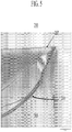
- FIG. 10 is a Weibull plot of failure probabilities obtained for sets of samples having low strength edges (Data set 1 in Table 1 and groups 1 and 2 in FIG. 10 ), and having high strength laser-cut edges (Data set 2 and groups 3 and 4 in FIG. 10 ), as described herein.
- the samples classified as having low edge strength have full-body laser-cut edges that contain shear and twist defects and/or changes in fracture steps and/or planes that are known as "hackles" (see FIGS. 5-8 ). Such hackles lead to failure of the edge ( FIG. 5 ).
- the high strength edges are also the product of full-body laser cutting
- the laser cutting parameters e.g., speed of translation of the laser and quenching streams (if present) along the surface of the glass substrate, distance between the laser and the quenching stream, etc.
- speed of translation of the laser and quenching streams (if present) along the surface of the glass substrate, distance between the laser and the quenching stream, etc. have been optimized to eliminate hackles and other edge defects and thus produce a high strength edge ( FIG. 4 ).
- Edge strength testing was carried out up to a tensile stress of 280 MPa, The results of the edge strength testing are listed in Table 1, which lists the tensile stress at which individual samples failed.
- the term the "laser side,” refers to the surface of the sample exposed to the laser during the laser-cutting process, whereas the “backside” refers to the side of the sample opposite the laser side. If a sample did not fail at a tensile stress less than or equal to 280 MPa, the sample was deemed to have "passed” the edge strength test, as noted by "pass” in Table 1. Table 1. Results of edge strength testing. Sample No.
- backside and laser side data sets (Data set 1 in Table 1 and groups 1 and 2 in FIG. 10 ) of about 50 samples each, the failure probability at a stress level of 200 MPa ranged from 5% to 30%.
- Backside and laser side data sets for samples having high strength edges (Data set 2 in Table 1 and groups 3 and 4 in FIG. 10 ), each consisted of 27 samples. For this combined number of 54 samples, no failures occurred at stress levels of less than 200 MPa, and only two samples in each set failed below 280 MPa.
Landscapes
- Chemical & Material Sciences (AREA)
- Engineering & Computer Science (AREA)
- Ceramic Engineering (AREA)
- Materials Engineering (AREA)
- Organic Chemistry (AREA)
- Structural Engineering (AREA)
- Physics & Mathematics (AREA)
- Geochemistry & Mineralogy (AREA)
- Life Sciences & Earth Sciences (AREA)
- General Chemical & Material Sciences (AREA)
- Chemical Kinetics & Catalysis (AREA)
- Health & Medical Sciences (AREA)
- Optics & Photonics (AREA)
- Toxicology (AREA)
- Thermal Sciences (AREA)
- Surface Treatment Of Glass (AREA)
- Re-Forming, After-Treatment, Cutting And Transporting Of Glass Products (AREA)
- Glass Compositions (AREA)
- Manufacturing & Machinery (AREA)
Description
- Glass substrates are currently being used as protective covers or windows for display and touch sensor devices, as well as substrates for front and back planes of electronic devices. As such, these substrates are susceptible to mechanical failure originating at flaws at the edges of the substrate. Such flaws are either created during the cutting and edge finishing process or from contact damage occurring during handling and use.
- Edge finishing, which includes grinding, polishing, and/or etching of the edges of the substrate, attempts to eliminate major flaws that are generated during the cutting process and minimize chipping due to contact damage. In addition, such finishing processes have been focused on preventing damage due to edge impact from point sources. Finishing processes are generally capable of removing flaws generated during scribe and breaking processes and produce edge shapes that are more tolerant of edge impact. However, these finishing processes produce lower edge strength than is achievable. In addition, it is difficult to use such finishing processes when the substrate thickness is below about 0.3 mm. Due to the reduced contact area, substrates having thicknesses in this range are susceptible to breakage during edge impact, whether or not they have been edge finished.
US 6,815,070 B1 discloses a glass-plastic composite film.
DE 19810 325 A1 discloses a method for increasing the edge strength of a thin glass sheet.
WO 2007/140978 A1 discloses a method in which a glass pane is surrounded by a covering at least in sections.
US 6,120,908 discloses a method in which an oxide substrate is coated with a strengthening composition. - In a first aspect, a substrate comprising a sheet of either a glass, a glass ceramic, or a ceramic and having increased edge strength is provided as set out in claim 1. In a second aspect, a method of making the substrate is provided, as set out in claim 9.
- In one embodiment, the substrate has a thickness of up to about 0.6 mm.
- In another embodiment, the substrate has a thickness of up to about 0.1 mm.
- In another embodiment, the polymeric edge coating has a modulus of up to about 10 GPa.
- In another embodiment, each of the at least two parallel high strength edges is slot-drawn, fusion-drawn, re-drawn, or laser cut.
- In another embodiment, substrate comprises one of a borosilicate glass, an aluminoborosilicate glass, and an alkali aluminosilicate glass.
- In a further embodiment, the alkali aluminosilicate glass comprises: 60-70 mol% SiO2; 6-14 mol% Al2O3; 0-15 mol% B2O3; 0-15 mol% Li2O; 0-20 mol% Na2O; 0-10 mol% K2O; 0-8 mol% MgO; 0-10 mol% CaO; 0-5 mol% ZrO2; 0-1 mol% SnO2; 0-1 mol% CeO2; less than 50 ppm As2O3; and less than 50 ppm Sb2O3; wherein 12 mol% ≤ Li2O + Na2O + K2O ≤ 20 mol% and 0 mol% ≤ MgO + CaO ≤ 10 mol%.
- In a further embodiment, the alkali aluminosilicate glass comprises: 64 mol% ≤ SiO2 ≤ 68 mol%; 12 mol% ≤ Na2O ≤ 16 mol%; 8 mol% ≤ Al2O3 ≤ 12 mol%; 0 mol% ≤ B2O3 ≤ 3 mol%; 2 mol% ≤ K2O ≤ 5 mol%; 4 mol% ≤ MgO ≤ 6 mol%; and 0 mol% ≤ CaO ≤ 5 mol%, wherein: 66 mol% ≤ SiO2 + B2O3 + CaO ≤ 69 mol%; Na2O + K2O + B2O3 + MgO + CaO + SrO > 10 mol%; 5 mol% ≤ MgO + CaO + SrO ≤ 8 mol%; (Na2O + B2O3) - Al2O3 ≤ 2 mol%; 2 mol% ≤ Na2O - Al2O3 ≤ 6 mol%; and 4 mol% ≤ (Na2O + K2O) - Al2O3 ≤ 10 mol%, and wherein the glass has a liquidus viscosity of at least 130 kpoise.
- In a further embodiment, the alkali aluminosilicate glass comprises: 50-80 wt% SiO2; 2-20 wt% Al2O3; 0-15 wt% B2O3; 1-20 wt% Na2O; 0-10 wt% Li2O; 0-10 wt% K2O; and 0-5 wt% (MgO + CaO + SrO + BaO); 0-3 wt% (SrO + BaO); and 0-5 wt% (ZrO2 + TiO2), wherein 0 ≤ (Li2O + K2O)/Na2O ≤0.5.
- In another embodiment, the substrate has at least one strengthened surface layer extending from at least one of the first surface and the second surface to a depth of layer, wherein the strengthened surface layer is under a compressive stress.
- In a further embodiment, the strengthened surface layer is an ion-exchanged layer.
- In another embodiment, the substrate further comprises at least one layer deposited on at least one of the first surface and the second surface.
- In another embodiment, the substrate is a protective cover glass for at least one of a hand held electronic device, an information-related terminal, and a touch sensor device.
- In an embodiment of the method, In an embodiment of the method, the step of providing the sheet comprises forming a sheet by one of fusion-drawing, slot-drawing, and redrawing.
- In an embodiment of the method the step of providing the sheet comprises laser cutting the sheet to form the at least two parallel high strength edges.
-
-
FIGURES 1 and 3 are schematic representations of side views of the substrates showing typical edge profile designs in accordance with the invention andFIGURES 2 and 4 , show designs not in accordance with an embodiment of the invention; -
FIGURE 5 is an optical micrograph of and edge of a glass substrate; -
FIGURES 6-9 are optical micrographs of laser-cut edges; and -
FIGURE 10 is a Weibull plot of failure probabilities obtained for sample sets that were strength tested using a four-point bending test. - In the following description, like reference characters designate like or corresponding parts throughout the several views shown in the figures. It is also understood that, unless otherwise specified, terms such as "top," "bottom," "outward," "inward," and the like are words of convenience and are not to be construed as limiting terms. In addition, whenever a group is described as comprising at least one of a group of elements and combinations thereof, it is understood that the group may comprise, consist essentially of, or consist of any number of those elements recited, either individually or in combination with each other. Similarly, whenever a group is described as consisting of at least one of a group of elements or combinations thereof, it is understood that the group may consist of any number of those elements recited, either individually or in combination with each other. Unless otherwise specified, a range of values, when recited, includes both the upper and lower limits of the range, as well as any sub-ranges therebetween.
- Referring to the drawings in general and to FIGS.
land 3 in particular, it will be understood that the illustrations are for the purpose of describing particular embodiments and are not intended to limit the disclosure or appended claims thereto. The drawings are not necessarily to scale, and certain features and certain views of the drawings may be shown exaggerated in scale or in schematic in the interest of clarity and conciseness. - Glass substrates are currently being used as protective covers for display and touch applications, such as, but not limited to, portable communication and entertainment devices such as telephones, music players, video players, or the like; and as display screens for information-related terminals (IT) (e.g., portable or laptop computers) devices; as well as in other applications, such as electronic paper front plane and back plane substrates. Such glass substrates are susceptible to mechanical failures and breakage originating from edge flaws that are created either during the cutting and edge finishing process or from contact damage during handling, device fabrication, and use.
- A substrate having increased edge strength is provided by eliminating the creation of strength limiting defects along the edges of the substrate and preserving the bend strength of the edge. The substrate comprises a sheet of either a glass, a glass ceramic, or a ceramic. Although the substrate may be referred to herein solely as a glass substrate, it is understood that the description is, unless otherwise specified, equally applicable to glass ceramic and ceramic materials, as well as multi-layer structures comprising discrete glass, glass-ceramic, and ceramic compositions. The sheet has a first surface, a second surface, and at least two parallel high strength edges joining the first and second surfaces. In one embodiment, the sheet may further include a polymeric coating on the first surface, second surface, or both. Each of the two parallel high strength edges has a bend strength that is capable of less than about 2% failure probability at a stress level of 200 MPa over a test length of 50 mm. An edge coating of a polymeric material covers at least a portion of each of the high strength edges, preserving the high strength edges from subsequent damage and preventing contamination of the edge. For example, once applied to the edge, the edge coating prevents crack systems from forming on the edge. In those embodiments in which a surface coating is present, the surface coating and edge coating can have compositions that are different from each other, and may be applied to the substrate at different times and by different processes.
- In one embodiment, the substrate has a thickness of up to about 0.6 mm and, in another embodiment, has a thickness of up to about 0.4 mm. The substrate, in a third embodiment, has a thickness of up to about 0.1 mm. Due to their reduced contact area, substrates having thicknesses less than or equal to about 0.1 mm are particularly susceptible to breakage during edge impact, whether or not they have finished edges. Moreover, edge finishing using techniques such as polishing and the like are either ineffective or have not been demonstrated at thicknesses less than or equal to about 0.1 mm. It is therefore better to rely on a forming process and/or a cutting process that yields a high strength edge rather than use a finishing process to average the edge strength to a lower, uniform value.
- In one embodiment, the at least two parallel high strength edges are created directly by a forming process. Such forming processes typically involve heating the glass to a temperature above the anneal point (i.e., the temperature at which the viscosity η of a glass equals 1013 Poise; also referred to as the anneal temperature). Non-limiting examples of such forming processes include down-draw processes. Such down-draw processes are known in the art and include slot-draw processes, fusion-draw processes, re-draw processes, and the like.
- Alternatively, the high strength edges may be created by high strength cutting methods that include, but are not limited to, laser cutting techniques. Such laser cutting techniques include full-body laser separation using a CO2 laser having a wavelength of 10.6 µm. In CO2 full body laser cutting, a glass substrate is heated to a temperature that is near (i.e., ± 50°C) the strain point of the glass to create a vent. Although the laser cutting of a glass substrate is described herein, it is understood that the laser cutting methods described herein may be used to cut or separate the other types of substrates (e.g., ceramics, glass ceramics) described herein). In one embodiment, the glass is then rapidly quenched - typically with a water jet - after heating by the laser. Quenching produces a tensile force over the glass vent, opening the vent in the direction of the relative motion of the glass substrate. Quenching creates a tensile force on the side of the glass substrate irradiated by the laser (the laser side) that is strong enough to open up and propagate the vent in the glass. Since the tensile force on the laser side must be balanced over the thickness of the glass, a compressive force is generated on the side of the glass opposite the laser side (the back side), creating a bending momentum in the glass. Due to the bending momentum, edge quality is difficult to control. The laser-cut edge can behave differently, depending on whether tension is applied on the laser side or the back side of the glass substrate. Severe bending can induce fracture surface features that act as flaws and decrease the edge strength of the glass. The dominating fracture mode in samples having low edge strength are shear and twist defects or changes in fracture steps and planes that are known as "hackles." Low strength edges often fail due to the presence of twist hackles on the edge face. An optical micrograph of an
edge 205 of a laser-cut glass substrate 200 having atwist hackle 210 is shown inFIG. 5 . InFIG. 5 ,twist hackle 210 runs from the back side 202 (top right inFIG. 5 ) to the bottom left of theglass substrate 200. - High strength edges can be formed by CO2 full body laser cutting by eliminating flaws such as twist hackles and the like. Such flaws can be eliminated in cutting regimes in which the temperature is balanced over the thickness of the substrate at suitable laser power densities. The median strength of such laser-cut edges is typically greater than about 400 MPa. The effect of laser power and distance between the laser beam and the quenching water jet are shown in
FIGS. 3-9 , which are optical micrographs of laser-cut edges. The laser power and distance between the laser and water jet used on the samples shown inFIGS. 6-9 are: a)FIG. 6 : 26 W power, 14 mm distance; b)FIG. 7 : 26 W power, 24 mm distance; c)FIG. 8 : 35 W power, 14 mm distance; and d)FIG. 9 : 35 W power, 24 mm distance.Hackles 310 were observed under the laser cutting conditions used inFIGS. 6-8 , whereas the conditions used to cut the edge shown inFIG. 9 produced an edge that is free of any visible hackles or other flaws. - One non-limiting example of such full body CO2 laser cutting or separation technique in which cutting parameters are optimized to eliminate hackles that lead to low strength edges is described in
U.S. Patent Application No. 12/469794, by Sean M. Garner et al. 12/388,935, by Anatoli A. Abramov et al. substrate 100. -
FIGS. 1-4 are schematic representations of side views of the substrates described herein, showing typical edge profile designs withFIGS 2 and 4 being designs not in accordance with the invention.Substrate 100 has afirst surface 102, asecond surface 104, and at least two parallel high strength edges 110, 112, one of which is shown inFIGS. 1-4 . In one embodiment, each of the at least two parallel high strength edges has a rectangular profile 110 (FIGS. 1 ).Rectangular edge profile 110, in one embodiment, is formed by a cutting process such as, but not limited to, the laser cutting in separation techniques described herein. In a second embodiment, each of the at least two parallel high strength edges has a rounded profile 112 (FIGS. 3 ). Roundededge profile 112, in one embodiment, is formed by a slot-draw process. Edge profiles 110, 112 have edge faces that are substantially free of visible defects and thus have a bend strength that is greater than edges formed by mechanical polishing methods. Edges that are finished by chemical methods, such as edging of the like, produce rounded edge profiles having edge strengths that are also greater than those achieved by mechanical finishing. However, chemical etching processes can be incompatible with the substrate or structures that are fabricated on the substrate. Each of the high strength edges 110, 112 ofsubstrate 100 has a bend strength, such as a four-point bend edge strength, capable of less than 2% failure probability at a stress level of 200 MPa over a test length of 50 mm. - At least a portion of the high strength edges are coated with
edge coating 120 comprising a polymeric material (FIGS. 1-4 ) such as, but not limited to, those flexible or elastic polymeric materials known in the art. In one embodiment, the polymeric material comprises at least one of a silicone, an epoxy, an acrylate, a urethane, and combinations thereof having a modulus of less than about 10 GPa. Non-limiting examples of polymeric materials include UV curable optical adhesives or optical cements such as those manufactured by Norland™ Optical Adhesives (NOA60. NOA61, NOA63, NOA65, NOA68, NOA68T, NOA71, NOA72, NOA73, NOA74, NOA75, NOA76, NOA78, NOA81, NOA83H, NOA84, NOA88, NOA89), Dow Corning™ (Sylgard 184 and other thermally curing silicones), Dymax™, and others. In particular, non-limiting examples of such materials are described inU.S. Patent 3,986,997 by Howard A. Clark , entitled "Pigment-Free Coating Compositions," issued October 19, 1976, which describes acidic dispersions of colloidal silica and hydroxylated sesquisiloxane in an alcohol-water medium to provide abrasion resistant coatings. -
Edge coating 120 of the polymeric material has a thickness in a range from about 5 µm up to about 50 µm, and can be applied by those methods known in the art, such as dipping, painting, spraying, dispensing from a die, or the like. If the substrate is used for device manufacturing or if a patterned layer is formed on the substrate, the edge coating can be applied to the substrate either before or after device processing.Edge coating 120 primarily serves a mechanical function, preserving the high bend strength of the as-formed or cut high strength edges by protecting the substrate edge from further damage. In some embodiments,edge coating 120 need not be transparent. - The at least two parallel high strength edges are unfinished; i.e., they are as-formed and not finished by mechanical or chemical means; i.e., they are neither ground nor etched. The combination of the at least two parallel high strength edges and
edge coating 120 described herein does not require such finishing. Consequently, the number of process steps to makesubstrate 100 is decreased while overall substrate yield is increased. - As previously stated,
edge coating 120 coats at least a portion of each high strength edge. In some examples not in accordance with the invention shown inFIGS. 2 and 4 , edge coating additionally covers a portion of first andsecond surfaces invention substrate 100 does not have e protective coatings onfirst surface 102 andsecond surface 104. - In some instances, various coatings or films, such as strengthening, anti-scratch, anti-reflective, anti-glare coatings or films, or the like, such as those are known in the art, may be applied to at least one of
first surface 102 andsecond surface 104 ofsubstrate 100.Edge coating 120 need not have the same composition of such coatings, nor does edge coating 120 have to be applied at the same time as any other surface coating that may be present. For example, a coating may be applied to at least one offirst surface 102 andsecond surface 104 immediately aftersubstrate 100 is formed, whereas high strength edges can be cut into or otherwise formed onsubstrate 100 andedge coatings 120 applied to the high strength edges after a device is fabricated onsubstrate 120, or just beforesubstrate 100 is incorporated into a device. - The
substrate 100 comprises, consists essentially of, or consists of a glass, a glass ceramic material, or a ceramic material suitable for applications such as thin (i.e., ≤0.6 mm or, alternatively, ≤ 0.4 mm). The substrate can have either a single, multiple, or graded composition, such as that produced by chemical strengthening of glass by ion exchange and, in one embodiment, is rollable (i.e., a continuous sheet of the substrate can be rolled up) or bendable. Non-limiting examples of such glass ceramic and ceramic materials include β-spogamene, β-quartz, nepheline, and the like. - In some embodiments, the
substrate 100 comprises, consists essentially of, or consists of one of a borosilicate glass, an aluminoborosilicate glass, and an alkali aluminosilicate glass. In one embodiment, the substrate is an alkali aluminosilicate glass comprising: 60-70 mol% SiO2; 6-14 mol% Al2O3; 0-15 mol% B2O3; 0-15 mol% Li2O; 0-20 mol% Na2O; 0-10 mol% K2O; 0-8 mol% MgO; 0-10 mol% CaO; 0-5 mol% ZrO2; 0-1 mol% SnO2; 0-1 mol% CeO2; less than 50 ppm As2O3; and less than 50 ppm Sb2O3; wherein 12 mol% ≤ Li2O + Na2O + K2O ≤ 20 mol% and 0 mol% ≤ MgO + CaO ≤ 10 mol%. In another embodiment, the alkali aluminosilicate glass comprises 64 mol% ≤ SiO2 ≤ 68 mol%; 12 mol% ≤ Na2O ≤ 16 mol%; 8 mol% ≤ Al2O3 ≤ 12 mol%; 0 mol% ≤ B2O3 ≤ 3 mol%; 2 mol% ≤ K2O ≤ 5 mol%; 4 mol% ≤ MgO ≤ 6 mol%; and 0 mol% ≤ CaO ≤ 5 mol%, wherein: 66 mol% ≤ SiO2 + B2O3 + CaO ≤ 69 mol%; Na2O + K2O + B2O3 + MgO + CaO + SrO > 10 mol%; 5 mol% ≤ MgO + CaO + SrO ≤ 8 mol%; (Na2O + B2O3) - Al2O3 ≤ 2 mol%; 2 mol% ≤ Na2O - Al2O3 ≤ 6 mol%; and 4 mol% ≤ (Na2O + K2O) - Al2O3 ≤ 10 mol%. In a third embodiment, the alkali aluminosilicate glass comrpises: 50-80 wt% SiO2; 2-20 wt% Al2O3; 0-15 wt% B2O3; 1-20 wt% Na2O; 0-10 wt% Li2O; 0-10 wt% K2O; and 0-5 wt% (MgO + CaO + SrO + BaO); 0-3 wt% (SrO + BaO); and 0-5 wt% (ZrO2 + TiO2), wherein 0 ≤ (Li2O + K2O)/Na2O ≤0.5. - In one particular embodiment, the alkali aluminosilicate glass has the composition: 66.7 mol% SiO2; 10.5 mol% Al2O3; 0.64 mol% B2O3; 13.8 mol% Na2O; 2.06 mol% K2O; 5.50 mol% MgO; 0.46 mol% CaO; 0.01 mol% ZrO2; 0.34 mol% As2O3; and 0.007 mol% composition: 66.4 mol% SiO2; 10.3 mol% Al2O3; 0.60 mol% B2O3; 4.0 mol% Na2O; 2.10 mol% K2O; 5.76 mol% MgO; 0.58 mol% CaO; 0.01 mol% ZrO2; 0.21 mol% SnO2; and 0.007 mol% Fe2O3. The alkali aluminosilicate glass is, in some embodiments, substantially free of lithium, whereas in other embodiments, the alkali aluminosilicate glass is substantially free of at least one of arsenic, antimony, and barium.
- The alkali aluminosilicate glass, in one embodiment, is down-drawable; i.e., formable by methods such as slot-draw or fusion-draw processes that are known in the art. In these instances, the glass has a liquidus viscosity of at least 130 kpoise. Non-limiting examples of such alkali aluminosilicate glasses are described in
U.S. Patent Application No. 11/888,213, by Adam J. Ellison et al. U.S. Provisional Patent Application 60/930,808, filed on May 22, 2007 U.S. Patent Application No. 12/277,573, by Matthew J. Dejneka et al. U.S. Provisional Patent Application 61/004,677, filed on November 29, 2007 U.S. Patent Application No. 12/392,577, by Matthew J. Dejneka et al. U.S. Provisional Patent Application No. 61/067,130, filed February 26, 2008 U.S. Patent Application No. 12/393,241 by Matthew J. Dejneka et al. U.S. Provisional Patent Application No. 61/067,732, filed February 29, 2008 U.S. Provisional Patent Application No. 61/087324, by Kristen L. Barefoot et al. - In one embodiment,
substrate 100 comprises, consists essentially of, or consists of an alkali aluminosilicate glass that is either thermally or chemically strengthened. The strengthened alkali aluminosilicate glass has strengthened surface layers extending fromfirst surface 102 andsecond surface 104 to a depth of layer below each surface. The strengthened surface layers are under compressive stress, whereas a central region ofsubstrate 100 is under tension, or tensile stress, so as to balance forces within the glass. In thermal strengthening (also referred to herein as "thermal tempering"),substrate 100 is heated up to a temperature that is greater than the strain point of the glass but below the softening point of the glass and rapidly cooled to a temperature below the strain point to create strengthened layers at the surfaces of the glass. In another embodiment,substrate 100 can be strengthened chemically by a process known as ion exchange. In this process, ions in the surface layer of the glass are replaced by - or exchanged with - larger ions having the same valence or oxidation state. In one particular embodiment, the ions in the surface layer and the larger ions are monovalent alkali metal cations, such as Li+ (when present in the glass), Na+, K+, Rb+, and Cs+. Alternatively, monovalent cations in the surface layer may be replaced with monovalent cations other than alkali metal cations, such as Ag+ or the like. - Ion exchange processes are typically carried out by immersing glass in a molten salt bath containing the larger ions to be exchanged with the smaller ions in the glass. It will be appreciated by those skilled in the art that parameters for the ion exchange process, including, but not limited to, bath composition and temperature, immersion time, the number of immersions of the glass in a salt bath (or baths), use of multiple salt baths, additional steps such as annealing, washing, and the like, are generally determined by the composition of the glass and the desired depth of layer and compressive stress of the glass as a result of the strengthening operation. By way of example, ion exchange of alkali metal-containing glasses may be achieved by immersion in at least one molten bath containing a salt such as, but not limited to, nitrates, sulfates, and chlorides of the larger alkali metal ion. The temperature of the molten salt bath typically is in a range from about 380°C up to about 450°C, while immersion times range from about 15 minutes up to about 16 hours. However, temperatures and immersion times different from those described above may also be used. Such ion exchange treatments typically result in strengthened alkali aluminosilicate glasses having depths of layer ranging from about 10 µm up to at least 50 µm with a compressive stress ranging from about 200 MPa up to about 800 MPa, and a central tension of less than about 100 MPa.
- Non-limiting examples of ion exchange processes are provided in the U.S. patent applications and provisional patent applications that have been previously referenced hereinabove. In addition, non-limiting examples of ion exchange processes in which glass is immersed in multiple ion exchange baths, with washing and/or annealing steps between immersions, are described in
U.S. Provisional Patent Application No. 61/079,995, by Douglas C. Allan et al. U.S. Provisional Patent Application No.61/084,398, by Christopher M. Lee et al. - A method of making a substrate having increased edge strength, described hereinabove, is also provided. A sheet comprising at least one of a glass, glass ceramic, and a ceramic is first provided. The sheet has a first surface, a second surface, and at least two parallel high strength edges. As previously described herein, the at least two parallel high strength edges are, in one embodiment, created directly by a forming process, such as down-draw processes, fusion-draw processes, slot-draw processes, re-drawing processes, and the like, that involves heating the sheet to a temperature above the anneal point of the sheet. Alternatively, the high strength edges may be created by high strength cutting methods that include, but are not limited to, the laser cutting techniques described herein.
- A polymeric edge coating is then deposited on at least a portion of each of the two parallel high strength edges to form the substrate. The polymeric edge coating, in one embodiment, has a modulus of less than about 10 GPa, and comprises a polymeric material, such as those described hereinabove. Each of the high strength edges of the substrate has a bend strength, such as a four-point bend edge strength, capable of less than 2% failure probability at a stress level of 200 MPa over a test length of 50 mm.
- The following example illustrates some of the features and advantages of the substrate and methods described herein and is in no way intended to limit either the disclosure or the appended claims thereto.
- The edge strength of fusion-drawn Corning EAGLE XG™ aluminoborosilicate glass samples and full-body laser-cut edges, was tested using a four point bending test. Each sample tested had a length of 50 mm and a thickness of 0.63 mm. Testing of a given sample was stopped if a stress level of 280 MPa was reached without sample failure.
-
FIG. 10 is a Weibull plot of failure probabilities obtained for sets of samples having low strength edges (Data set 1 in Table 1 andgroups 1 and 2 inFIG. 10 ), and having high strength laser-cut edges (Data set 2 andgroups 3 and 4 inFIG. 10 ), as described herein. The samples classified as having low edge strength have full-body laser-cut edges that contain shear and twist defects and/or changes in fracture steps and/or planes that are known as "hackles" (seeFIGS. 5-8 ). Such hackles lead to failure of the edge (FIG. 5 ). Although the high strength edges are also the product of full-body laser cutting, the laser cutting parameters (e.g., speed of translation of the laser and quenching streams (if present) along the surface of the glass substrate, distance between the laser and the quenching stream, etc.) have been optimized to eliminate hackles and other edge defects and thus produce a high strength edge (FIG. 4 ). - Edge strength testing was carried out up to a tensile stress of 280 MPa, The results of the edge strength testing are listed in Table 1, which lists the tensile stress at which individual samples failed. The term the "laser side," refers to the surface of the sample exposed to the laser during the laser-cutting process, whereas the "backside" refers to the side of the sample opposite the laser side. If a sample did not fail at a tensile stress less than or equal to 280 MPa, the sample was deemed to have "passed" the edge strength test, as noted by "pass" in Table 1.
Table 1. Results of edge strength testing. Sample No. Tensile Stress (MPa) Tensile Stress (MPa) Data set 1 Data set 2Backside Laser Side Backside Laser Side 1 153 244 Pass Pass 2 Pass Pass Pass Pass 3 208 Pass Pass Pass 4 111 Pass Pass Pass 5 91 Pass 257 Pass 6 190 129 Pass Pass 7 Pass Pass Pass Pass 8 237 Pass Pass Pass 9 172 Pass Pass Pass 10 198 Pass Pass Pass 11 Pass Pass Pass Pass 12 Pass Pass Pass Pass 13 Pass Pass Pass Pass 14 222 140 Pass Pass 15 223 Pass Pass Pass 16 236 242 Pass 225 17 Pass Pass Pass Pass 18 Pass Pass Pass Pass 19 223 Pass Pass Pass 20 Pass Pass Pass Pass 21 Pass Pass Pass Pass 22 Pass Pass Pass Pass 23 Pass Pass Pass Pass 24 Pass Pass Pass Pass 25 Pass 170 226 Pass 26 149 204 Pass Pass 27 92 Pass Pass 224 28 Pass Pass 29 203 Pass 30 239 Pass 31 218 Pass 32 257 212 33 228 Pass 34 117 Pass 35 Pass Pass 36 Pass Pass 37 251 Pass 38 Pass Pass 39 Pass Pass 40 211 Pass 41 Pass Pass 42 158 Pass 43 178 Pass 44 165 Pass 45 Pass Pass 46 Pass Pass 47 131 Pass 48 Pass Pass 49 Pass Pass 50 Pass 51 Pass - For the samples having low strength edges, backside and laser side data sets (Data set 1 in Table 1 and
groups 1 and 2 inFIG. 10 ) of about 50 samples each, the failure probability at a stress level of 200 MPa ranged from 5% to 30%. Backside and laser side data sets for samples having high strength edges (Data set 2 in Table 1 andgroups 3 and 4 inFIG. 10 ), each consisted of 27 samples. For this combined number of 54 samples, no failures occurred at stress levels of less than 200 MPa, and only two samples in each set failed below 280 MPa. These results demonstrate the ability to create high strength edges capable of < 2% failure probability at a stress level of 200 MPa or greater. - While typical embodiments have been set forth for the purpose of illustration, various modifications, adaptations, and alternatives may occur to one skilled in the art without departing from the scope of the appended claims.
Claims (11)
- A substrate (100), the substrate (100) comprising:a. a sheet comprising at least one of a glass, a ceramic, and a glass ceramic, the sheet having a first surface (102), a second surface (104), and at least two parallel high strength edges joining the first surface (102) and the second surface (104), wherein each of the at least two parallel high strength edges has a bend strength capable of less than 2% failure probability at a stress level of 200 MPa over a test length of 50 mm; andb. a polymeric edge coating (120) covering at least a portion of each of the at least two parallel high strength edges, wherein the polymeric edge coating (120) has a thickness in a range from 5 µm to 50 µm and protects each of the at least two parallel high strength edges from the introduction of defects and damage,characterised in that each of the at least two parallel high strength edges is unfinished; in that the first surface (102) of the sheet and the second surface (104) of the sheet are each entirely free of the polymeric edge coating (120); and in that the polymeric edge coating (120) comprises at least one of a silicone, an epoxy, an acrylate, a urethane, and combinations thereof.
- The substrate (100) according to Claim 1, wherein the substrate (100) has a thickness of up to 0.6 mm.
- The substrate (100) according to Claim 2, wherein the substrate (100) has a thickness of up to 0.1 mm.
- The substrate (100) according to any one of Claims 1-3, wherein the polymeric edge coating (120) has a modulus of up to 10 GPa.
- The substrate (100) according to any one of Claims 1-4, wherein the substrate (100) has at least one strengthened surface layer extending from at least one of the first surface (102) and the second surface (104) to a depth of layer, wherein the strengthened surface layer is under a compressive stress.
- The substrate (100) according to Claim 5, wherein the strengthened surface layer is an ion-exchanged layer.
- The substrate (100) according to any one of Claims 1-6, further comprising at least one layer deposited on at least one of the first surface (102) and the second surface (104).
- The substrate (100) according to any one of Claims 1-7, wherein the substrate (100) is a protective cover glass for at least one of a hand held electronic device, an information-related terminal, and a touch sensor device.
- A method of making a substrate (100), the method comprising the steps of:a. providing a sheet comprising at least one of a glass, a glass ceramic, and a ceramic and having a first surface (102) and a second surface (104) that are substantially parallel to each other, and at least two parallel high strength edges between the first surface (102) and the second surface (104), wherein each of the at least two parallel edges has a bend strength capable of less than 2% failure probability at a stress level of 200 MPa over a test length of 50 mm; andb. depositing a polymeric edge coating (120) on at least a portion of each of the at least two parallel high strength edges to form the substrate (100), wherein the polymeric edge coating (120) has a thickness in a range from 5 µm to 50 µm,characterised in that each of the at least two parallel high strength edges is unfinished; in that the first surface (102) of the sheet and the second surface (104) of the sheet are each entirely free of the polymeric edge coating (120); and in that the polymeric edge coating (120) comprises at least one of a silicone, an epoxy, an acrylate, a urethane, and combinations thereof.
- The method according to Claim 9, wherein the step of providing the sheet comprises forming a sheet by one of fusion-drawing, slot-drawing, and redrawing.
- The method according to Claim 9 or Claim 10, wherein the step of cutting the sheet comprises laser cutting the sheet to form the at least two parallel high strength edges.
Applications Claiming Priority (2)
| Application Number | Priority Date | Filing Date | Title |
|---|---|---|---|
| US18023009P | 2009-05-21 | 2009-05-21 | |
| PCT/US2010/035705 WO2010135614A1 (en) | 2009-05-21 | 2010-05-21 | Thin substrates having mechanically durable edges |
Publications (2)
| Publication Number | Publication Date |
|---|---|
| EP2432744A1 EP2432744A1 (en) | 2012-03-28 |
| EP2432744B1 true EP2432744B1 (en) | 2020-07-15 |
Family
ID=42537912
Family Applications (1)
| Application Number | Title | Priority Date | Filing Date |
|---|---|---|---|
| EP10724205.9A Active EP2432744B1 (en) | 2009-05-21 | 2010-05-21 | Thin substrates having mechanically durable edges |
Country Status (7)
| Country | Link |
|---|---|
| US (1) | US9422188B2 (en) |
| EP (1) | EP2432744B1 (en) |
| JP (3) | JP2012527399A (en) |
| KR (1) | KR101631347B1 (en) |
| CN (1) | CN102438960B (en) |
| TW (1) | TWI558552B (en) |
| WO (1) | WO2010135614A1 (en) |
Families Citing this family (78)
| Publication number | Priority date | Publication date | Assignee | Title |
|---|---|---|---|---|
| WO2010135614A1 (en) * | 2009-05-21 | 2010-11-25 | Corning Incorporated | Thin substrates having mechanically durable edges |
| JP5532219B2 (en) * | 2010-01-18 | 2014-06-25 | 日本電気硝子株式会社 | Sheet glass cutting method and apparatus |
| US9302937B2 (en) | 2010-05-14 | 2016-04-05 | Corning Incorporated | Damage-resistant glass articles and method |
| CN102478727B (en) * | 2010-11-28 | 2016-04-06 | 宸鸿科技(厦门)有限公司 | The manufacture method of touch control display apparatus and display device, touch control display apparatus |
| TW201228824A (en) * | 2011-01-06 | 2012-07-16 | Corning Inc | Fully integrated touch articles with polymer edge protection |
| US20140054348A1 (en) * | 2011-06-08 | 2014-02-27 | Yasuo Teranishi | Method for cutting plate-like glass, and cutting device therefor |
| TWI572480B (en) | 2011-07-25 | 2017-03-01 | 康寧公司 | Laminated and ion-exchanged strengthened glass laminates |
| DE102011084129A1 (en) | 2011-10-07 | 2013-04-11 | Schott Ag | Glass foil with specially designed edge |
| DE102011084131A1 (en) * | 2011-10-07 | 2013-04-11 | Schott Ag | Glass foil with specially designed edge |
| DE102011084128A1 (en) | 2011-10-07 | 2013-04-11 | Schott Ag | Method for cutting a thin glass with special formation of the edge |
| CN103203926A (en) * | 2012-01-16 | 2013-07-17 | 晟铭电子科技股份有限公司 | Plate edge protection structure and manufacturing method thereof |
| IN2014DN07444A (en) | 2012-02-29 | 2015-04-24 | Corning Inc | |
| US9359251B2 (en) | 2012-02-29 | 2016-06-07 | Corning Incorporated | Ion exchanged glasses via non-error function compressive stress profiles |
| CN103304154A (en) * | 2012-03-15 | 2013-09-18 | 铭旺科技股份有限公司 | Reinforcing method for touch panel glass and structure thereof |
| WO2013154034A1 (en) * | 2012-04-10 | 2013-10-17 | 旭硝子株式会社 | Reinforced glass article and touch sensor integrated-type cover glass |
| US9199870B2 (en) | 2012-05-22 | 2015-12-01 | Corning Incorporated | Electrostatic method and apparatus to form low-particulate defect thin glass sheets |
| JP2015171955A (en) * | 2012-07-11 | 2015-10-01 | 旭硝子株式会社 | Method for manufacturing curved plate |
| JP2015171953A (en) * | 2012-07-11 | 2015-10-01 | 旭硝子株式会社 | Method for manufacturing functional substrate |
| JP2015171954A (en) * | 2012-07-11 | 2015-10-01 | 旭硝子株式会社 | Laminate-producing method |
| KR20140022238A (en) * | 2012-08-13 | 2014-02-24 | 삼성디스플레이 주식회사 | Display device |
| US10953633B2 (en) | 2012-08-31 | 2021-03-23 | Corning Incorporated | Strengthened thin glass-polymer laminates |
| TWI457309B (en) * | 2012-09-17 | 2014-10-21 | Wistron Corp | Strengthened structure of glass and manufacturing method thereof |
| US8960014B2 (en) | 2012-09-21 | 2015-02-24 | Corning Incorporated | Methods of validating edge strength of a glass sheet |
| US20140087193A1 (en) * | 2012-09-26 | 2014-03-27 | Jeffrey Scott Cites | Methods for producing ion exchanged glass and resulting apparatus |
| CN110698059B (en) * | 2012-10-04 | 2022-07-29 | 康宁股份有限公司 | Compressive stressed laminated glass articles made from photosensitive glass and methods of making the same |
| US9187364B2 (en) * | 2013-02-28 | 2015-11-17 | Corning Incorporated | Method of glass edge coating |
| US11079309B2 (en) | 2013-07-26 | 2021-08-03 | Corning Incorporated | Strengthened glass articles having improved survivability |
| US9573843B2 (en) | 2013-08-05 | 2017-02-21 | Corning Incorporated | Polymer edge-covered glass articles and methods for making and using same |
| TWI515620B (en) * | 2013-10-15 | 2016-01-01 | 恆顥科技股份有限公司 | Method of increasing strength of a panel edge |
| JP5622133B1 (en) * | 2013-10-25 | 2014-11-12 | 大日本印刷株式会社 | Manufacturing method of cover glass |
| CN104635963B (en) * | 2013-11-07 | 2018-02-23 | 群创光电股份有限公司 | Touch control display apparatus and its manufacture method |
| JP6183706B2 (en) * | 2013-11-26 | 2017-08-23 | 大日本印刷株式会社 | Cover glass and display device with cover glass |
| WO2015083832A1 (en) * | 2013-12-06 | 2015-06-11 | 電気化学工業株式会社 | Rigid substrate with protected end surfaces, and method for manufacturing same |
| CN104699292A (en) * | 2013-12-06 | 2015-06-10 | 胜华科技股份有限公司 | Method for strengthening substrate and substrate of touch device |
| TW201523363A (en) * | 2013-12-10 | 2015-06-16 | Wintek Corp | Cover substrate and touch panel |
| US20150183179A1 (en) * | 2013-12-31 | 2015-07-02 | Saint-Gobain Ceramics & Plastics, Inc. | Article comprising a transparent body including a layer of a ceramic material and a method of forming the same |
| US9488857B2 (en) | 2014-01-10 | 2016-11-08 | Corning Incorporated | Method of strengthening an edge of a glass substrate |
| KR102421381B1 (en) * | 2014-02-20 | 2022-07-18 | 코닝 인코포레이티드 | Methods and apparatus for cutting radii in flexible thin glass |
| US9517968B2 (en) | 2014-02-24 | 2016-12-13 | Corning Incorporated | Strengthened glass with deep depth of compression |
| JP2015166300A (en) * | 2014-03-04 | 2015-09-24 | 日立化成株式会社 | Method for producing glass sheet with resin and glass sheet with resin obtained by using the production method |
| CN106457475A (en) * | 2014-03-14 | 2017-02-22 | 康宁股份有限公司 | Sensor embedded in glass and process for making same |
| TW201537420A (en) * | 2014-03-28 | 2015-10-01 | Ghitron Technology Co Ltd | Black frame border reinforcing structure of glass substrate |
| TW201539267A (en) * | 2014-04-10 | 2015-10-16 | Wintek Corp | Decoration plate and touch panel |
| JPWO2015166891A1 (en) * | 2014-04-30 | 2017-04-20 | 旭硝子株式会社 | Glass |
| JP6295846B2 (en) * | 2014-06-17 | 2018-03-20 | 日産化学工業株式会社 | Composition for forming glass protective film and glass protective film |
| JP6347160B2 (en) | 2014-06-17 | 2018-06-27 | 日本電気硝子株式会社 | Glass article and method for producing the same |
| TWI705889B (en) | 2014-06-19 | 2020-10-01 | 美商康寧公司 | Glasses having non-frangible stress profiles |
| JP2017152076A (en) * | 2014-07-09 | 2017-08-31 | パナソニックIpマネジメント株式会社 | Organic EL element and lighting device |
| US9919958B2 (en) | 2014-07-17 | 2018-03-20 | Corning Incorporated | Glass sheet and system and method for making glass sheet |
| US10144668B2 (en) | 2014-08-20 | 2018-12-04 | Corning Incorporated | Method and apparatus for yielding high edge strength in cutting of flexible thin glass |
| DE102014113150A1 (en) | 2014-09-12 | 2016-03-17 | Schott Ag | Glass element with low probability of breakage |
| CN105438662B (en) * | 2014-09-18 | 2018-06-29 | 旭硝子株式会社 | The packing method of glass plate, its manufacturing method, glass plate packing body and glass plate with rounding improvement film |
| CN115504681A (en) | 2014-10-07 | 2022-12-23 | 康宁股份有限公司 | Glass article having a defined stress distribution and method for producing the same |
| TWI734317B (en) | 2014-10-08 | 2021-07-21 | 美商康寧公司 | Glasses and glass ceramics including a metal oxide concentration gradient |
| US10150698B2 (en) | 2014-10-31 | 2018-12-11 | Corning Incorporated | Strengthened glass with ultra deep depth of compression |
| US20180009197A1 (en) * | 2014-11-04 | 2018-01-11 | Corning Incorporated | Bendable glass articles with alkali-free glass elements |
| TWI666189B (en) | 2014-11-04 | 2019-07-21 | 美商康寧公司 | Deep non-frangible stress profiles and methods of making |
| CN107108343B (en) | 2014-11-05 | 2020-10-02 | 康宁股份有限公司 | Glass article having non-planar features and alkali-free glass elements |
| DE102014119333A1 (en) * | 2014-12-22 | 2016-06-23 | Schott Ag | High-strength glass film with special formation of the edge and method for its production |
| EP3286151A1 (en) * | 2015-04-22 | 2018-02-28 | Corning Incorporated | Methods of edge finishing laminated glass structures |
| US11613103B2 (en) | 2015-07-21 | 2023-03-28 | Corning Incorporated | Glass articles exhibiting improved fracture performance |
| US10579106B2 (en) | 2015-07-21 | 2020-03-03 | Corning Incorporated | Glass articles exhibiting improved fracture performance |
| KR20180034586A (en) * | 2015-07-31 | 2018-04-04 | 코닝 인코포레이티드 | Reinforced asymmetric glass laminate |
| TWI596071B (en) * | 2015-08-25 | 2017-08-21 | 友達光電股份有限公司 | Display panel and method for manufacturing the same |
| CN108137396B (en) * | 2015-10-14 | 2022-04-26 | 康宁股份有限公司 | Laminated glass article having a defined stress profile and method of forming the same |
| DE202016008722U1 (en) | 2015-12-11 | 2019-03-21 | Corning Incorporated | Fusion-formable glass-based articles with a metal oxide concentration gradient |
| EP3904302A1 (en) | 2016-04-08 | 2021-11-03 | Corning Incorporated | Glass-based articles including a metal oxide concentration gradient |
| KR20180132077A (en) | 2016-04-08 | 2018-12-11 | 코닝 인코포레이티드 | A glass-based article comprising a stress profile comprising two regions, and a manufacturing method |
| WO2017195752A1 (en) * | 2016-05-09 | 2017-11-16 | 日立化成株式会社 | Photocurable resin composition, photocurable coating, and cured product |
| CN110678487B (en) * | 2017-03-31 | 2021-10-15 | 昭和电工材料株式会社 | Curable resin composition, glass member, display device, and mobile terminal |
| CN107734113A (en) * | 2017-10-31 | 2018-02-23 | 广东欧珀移动通信有限公司 | Curved surface cover plate and preparation method thereof, mobile terminal |
| KR102491760B1 (en) | 2017-12-04 | 2023-01-26 | 삼성디스플레이 주식회사 | Display device and method for manufacturing display device |
| KR102579100B1 (en) * | 2018-10-10 | 2023-09-14 | 쇼오트 글라스 테크놀로지스 (쑤저우) 코퍼레이션 리미티드. | Ultra-thin glass ceramic article and method for manufacturing ultra-thin glass ceramic article |
| US11447416B2 (en) * | 2018-12-20 | 2022-09-20 | Apple Inc. | Strengthened covers for electronic devices |
| US20220102230A1 (en) | 2019-02-21 | 2022-03-31 | Sony Semiconductor Solutions Corporation | Semiconductor substrate and semiconductor module |
| CN111393032B (en) * | 2020-04-13 | 2022-07-08 | Oppo广东移动通信有限公司 | Microcrystalline glass cover plate, flexible screen assembly, electronic equipment and microcrystalline glass cover plate processing method |
| KR20230021709A (en) * | 2020-06-04 | 2023-02-14 | 코닝 인코포레이티드 | Glass surface treatment method and treated glass products |
| CN116161867B (en) * | 2023-02-27 | 2023-12-15 | 广州触沃电子有限公司 | Intelligent capacitor integrated machine |
Family Cites Families (32)
| Publication number | Priority date | Publication date | Assignee | Title |
|---|---|---|---|---|
| US3577256A (en) * | 1969-06-26 | 1971-05-04 | Owens Illinois Inc | Scratch and abrasion resistant coatings for glass |
| US3986997A (en) | 1974-06-25 | 1976-10-19 | Dow Corning Corporation | Pigment-free coating compositions |
| JPS60251138A (en) * | 1984-05-28 | 1985-12-11 | Hoya Corp | Method for cutting glass |
| US5220358A (en) | 1991-07-15 | 1993-06-15 | Corning Incorporated | Edge coating for laminated lenses |
| US5674790A (en) * | 1995-12-15 | 1997-10-07 | Corning Incorporated | Strengthening glass by ion exchange |
| JP3791962B2 (en) * | 1996-04-22 | 2006-06-28 | 竹松工業株式会社 | Glass plate having edge protector and method for producing the same |
| JP3395538B2 (en) | 1996-09-17 | 2003-04-14 | 日本板硝子株式会社 | Shock resistant glass |
| US6120908A (en) * | 1997-09-08 | 2000-09-19 | Elf Atochem North America, Inc. | Strengthening flat glass by edge coating |
| DE19810325A1 (en) * | 1998-03-11 | 1999-09-16 | Karl Otto Platz | Increasing the edge strength of thin glass sheets |
| TW419867B (en) * | 1998-08-26 | 2001-01-21 | Samsung Electronics Co Ltd | Laser cutting apparatus and method |
| EP1048628A1 (en) * | 1999-04-30 | 2000-11-02 | Schott Glas | Polymer coated glassfoil substrate |
| WO2000041978A1 (en) | 1999-01-11 | 2000-07-20 | Schott Display Glas Gmbh | Polymer-coated thin-glass film substrates |
| JP2002054971A (en) | 2000-08-08 | 2002-02-20 | Nidai Seiko:Kk | Kerosene residual quantity detecting device |
| JPWO2005000762A1 (en) | 2003-06-30 | 2006-08-31 | 日本板硝子株式会社 | Edge protection member, glass panel provided with the protection member, and edge protection method for glass panel |
| SG112980A1 (en) | 2003-12-19 | 2005-07-28 | Asahi Glass Co Ltd | Glass substrate for magnetic disks and process for its production |
| JP2005314198A (en) * | 2004-04-26 | 2005-11-10 | Lemi Ltd | Laser apparatus for cutting glass |
| JP3908236B2 (en) | 2004-04-27 | 2007-04-25 | 株式会社日本製鋼所 | Glass cutting method and apparatus |
| US7231786B2 (en) * | 2004-07-29 | 2007-06-19 | Corning Incorporated | Process and device for manufacturing glass sheet |
| JP4179314B2 (en) | 2005-09-13 | 2008-11-12 | 株式会社レミ | Full-cut cleaving device for brittle materials |
| JP4524249B2 (en) * | 2005-12-28 | 2010-08-11 | 日本板硝子株式会社 | WINDOW GLASS AND MANUFACTURING METHOD THEREOF |
| DE102006025912A1 (en) * | 2006-06-02 | 2007-12-06 | Fraunhofer-Gesellschaft zur Förderung der angewandten Forschung e.V. | Glass pane and process for producing the glass pane |
| JP2008062489A (en) | 2006-09-07 | 2008-03-21 | Systec Inoue Corp | Splitting method for brittle material, and splitting apparatus for brittle material |
| US8017220B2 (en) | 2006-10-04 | 2011-09-13 | Corning Incorporated | Electronic device and method of making |
| CN101553351B (en) | 2006-12-19 | 2012-09-05 | 陶氏环球技术公司 | Encapsulated panel assemblies and method for making same |
| WO2008136872A2 (en) | 2006-12-22 | 2008-11-13 | Adriani Paul M | Structures for low cost, reliable solar modules |
| JP2008183599A (en) | 2007-01-31 | 2008-08-14 | Japan Steel Works Ltd:The | Method for working workpiece made of highly brittle and non-metallic material, and device therefor |
| JP5709379B2 (en) | 2007-02-28 | 2015-04-30 | コーニング インコーポレイテッド | Tempering glass with coating |
| US7666511B2 (en) * | 2007-05-18 | 2010-02-23 | Corning Incorporated | Down-drawable, chemically strengthened glass for cover plate |
| JP5005612B2 (en) * | 2008-05-24 | 2012-08-22 | 株式会社レミ | Full-cut cleaving method for brittle materials |
| KR20100070096A (en) * | 2008-12-17 | 2010-06-25 | (주)엘지하우시스 | Biodegradable materials for advertising and method of preparing thereof |
| US7998558B2 (en) * | 2009-02-27 | 2011-08-16 | Corning Incorporated | Glass sheet with protected edge, edge protector and method for making glass sheet using same |
| WO2010135614A1 (en) | 2009-05-21 | 2010-11-25 | Corning Incorporated | Thin substrates having mechanically durable edges |
-
2010
- 2010-05-21 WO PCT/US2010/035705 patent/WO2010135614A1/en active Application Filing
- 2010-05-21 JP JP2012512053A patent/JP2012527399A/en active Pending
- 2010-05-21 TW TW099116356A patent/TWI558552B/en not_active IP Right Cessation
- 2010-05-21 EP EP10724205.9A patent/EP2432744B1/en active Active
- 2010-05-21 CN CN201080023222.5A patent/CN102438960B/en not_active Expired - Fee Related
- 2010-05-21 US US13/266,548 patent/US9422188B2/en not_active Expired - Fee Related
- 2010-05-21 KR KR1020117030519A patent/KR101631347B1/en active IP Right Grant
-
2014
- 2014-10-01 JP JP2014202960A patent/JP2015071533A/en active Pending
-
2016
- 2016-01-06 JP JP2016001040A patent/JP6227019B2/en not_active Expired - Fee Related
Non-Patent Citations (1)
| Title |
|---|
| None * |
Also Published As
| Publication number | Publication date |
|---|---|
| WO2010135614A1 (en) | 2010-11-25 |
| JP2012527399A (en) | 2012-11-08 |
| KR101631347B1 (en) | 2016-06-16 |
| KR20120026098A (en) | 2012-03-16 |
| CN102438960B (en) | 2015-06-24 |
| TWI558552B (en) | 2016-11-21 |
| JP6227019B2 (en) | 2017-11-08 |
| JP2016128376A (en) | 2016-07-14 |
| US20120040146A1 (en) | 2012-02-16 |
| EP2432744A1 (en) | 2012-03-28 |
| CN102438960A (en) | 2012-05-02 |
| JP2015071533A (en) | 2015-04-16 |
| US9422188B2 (en) | 2016-08-23 |
| TW201103744A (en) | 2011-02-01 |
Similar Documents
| Publication | Publication Date | Title |
|---|---|---|
| EP2432744B1 (en) | Thin substrates having mechanically durable edges | |
| KR102302163B1 (en) | Ion Exchange Processes and Chemically Strengthened Glass Substrates Resulting Therefrom | |
| EP2323957B1 (en) | Strengthened glass articles and methods of making | |
| US10071933B2 (en) | Chemically toughened flexible ultrathin glass | |
| EP2609047B1 (en) | Two-step method for strengthening glass | |
| EP2762460B1 (en) | Chemically strengthened glass plate and method for manufacturing same | |
| EP2736855B1 (en) | Laminated and ion-exchanged strengthened glass laminates and their manufacturing method | |
| WO2019055745A1 (en) | Textured glass-based articles with scratch resistance and methods of making the same | |
| EP3577086A1 (en) | Coated glass-based articles with engineered stress profiles | |
| US20220064061A1 (en) | Thin glass substrate with high bending strength and method for producing same | |
| WO2019108826A1 (en) | Method of increasing iox processability on glass articles with multiple thicknesses | |
| KR20160147271A (en) | Antimicrobial Article with Functional Coating and Methods for Making the Antimicrobial Article | |
| EP3519368A1 (en) | Glass-based articles with engineered stress profiles and methods of manufacture |
Legal Events
| Date | Code | Title | Description |
|---|---|---|---|
| PUAI | Public reference made under article 153(3) epc to a published international application that has entered the european phase |
Free format text: ORIGINAL CODE: 0009012 |
|
| 17P | Request for examination filed |
Effective date: 20111027 |
|
| AK | Designated contracting states |
Kind code of ref document: A1 Designated state(s): AL AT BE BG CH CY CZ DE DK EE ES FI FR GB GR HR HU IE IS IT LI LT LU LV MC MK MT NL NO PL PT RO SE SI SK SM TR |
|
| DAX | Request for extension of the european patent (deleted) | ||
| STAA | Information on the status of an ep patent application or granted ep patent |
Free format text: STATUS: EXAMINATION IS IN PROGRESS |
|
| 17Q | First examination report despatched |
Effective date: 20161111 |
|
| GRAP | Despatch of communication of intention to grant a patent |
Free format text: ORIGINAL CODE: EPIDOSNIGR1 |
|
| STAA | Information on the status of an ep patent application or granted ep patent |
Free format text: STATUS: GRANT OF PATENT IS INTENDED |
|
| RIC1 | Information provided on ipc code assigned before grant |
Ipc: C03B 33/09 20060101ALI20190409BHEP Ipc: C04B 41/82 20060101ALI20190409BHEP Ipc: C04B 41/00 20060101ALI20190409BHEP Ipc: C04B 41/45 20060101ALI20190409BHEP Ipc: C03C 17/00 20060101AFI20190409BHEP Ipc: C04B 41/83 20060101ALI20190409BHEP Ipc: C03C 17/28 20060101ALI20190409BHEP |
|
| INTG | Intention to grant announced |
Effective date: 20190426 |
|
| GRAS | Grant fee paid |
Free format text: ORIGINAL CODE: EPIDOSNIGR3 |
|
| GRAJ | Information related to disapproval of communication of intention to grant by the applicant or resumption of examination proceedings by the epo deleted |
Free format text: ORIGINAL CODE: EPIDOSDIGR1 |
|
| GRAL | Information related to payment of fee for publishing/printing deleted |
Free format text: ORIGINAL CODE: EPIDOSDIGR3 |
|
| STAA | Information on the status of an ep patent application or granted ep patent |
Free format text: STATUS: EXAMINATION IS IN PROGRESS |
|
| INTC | Intention to grant announced (deleted) | ||
| GRAP | Despatch of communication of intention to grant a patent |
Free format text: ORIGINAL CODE: EPIDOSNIGR1 |
|
| STAA | Information on the status of an ep patent application or granted ep patent |
Free format text: STATUS: GRANT OF PATENT IS INTENDED |
|
| GRAS | Grant fee paid |
Free format text: ORIGINAL CODE: EPIDOSNIGR3 |
|
| INTG | Intention to grant announced |
Effective date: 20200515 |
|
| GRAA | (expected) grant |
Free format text: ORIGINAL CODE: 0009210 |
|
| STAA | Information on the status of an ep patent application or granted ep patent |
Free format text: STATUS: THE PATENT HAS BEEN GRANTED |
|
| AK | Designated contracting states |
Kind code of ref document: B1 Designated state(s): AL AT BE BG CH CY CZ DE DK EE ES FI FR GB GR HR HU IE IS IT LI LT LU LV MC MK MT NL NO PL PT RO SE SI SK SM TR |
|
| REG | Reference to a national code |
Ref country code: CH Ref legal event code: EP Ref country code: GB Ref legal event code: FG4D |
|
| REG | Reference to a national code |
Ref country code: IE Ref legal event code: FG4D |
|
| REG | Reference to a national code |
Ref country code: DE Ref legal event code: R096 Ref document number: 602010064914 Country of ref document: DE |
|
| REG | Reference to a national code |
Ref country code: AT Ref legal event code: REF Ref document number: 1290861 Country of ref document: AT Kind code of ref document: T Effective date: 20200815 |
|
| REG | Reference to a national code |
Ref country code: LT Ref legal event code: MG4D |
|
| REG | Reference to a national code |
Ref country code: AT Ref legal event code: MK05 Ref document number: 1290861 Country of ref document: AT Kind code of ref document: T Effective date: 20200715 |
|
| REG | Reference to a national code |
Ref country code: NL Ref legal event code: MP Effective date: 20200715 |
|
| PG25 | Lapsed in a contracting state [announced via postgrant information from national office to epo] |
Ref country code: ES Free format text: LAPSE BECAUSE OF FAILURE TO SUBMIT A TRANSLATION OF THE DESCRIPTION OR TO PAY THE FEE WITHIN THE PRESCRIBED TIME-LIMIT Effective date: 20200715 Ref country code: HR Free format text: LAPSE BECAUSE OF FAILURE TO SUBMIT A TRANSLATION OF THE DESCRIPTION OR TO PAY THE FEE WITHIN THE PRESCRIBED TIME-LIMIT Effective date: 20200715 Ref country code: PT Free format text: LAPSE BECAUSE OF FAILURE TO SUBMIT A TRANSLATION OF THE DESCRIPTION OR TO PAY THE FEE WITHIN THE PRESCRIBED TIME-LIMIT Effective date: 20201116 Ref country code: LT Free format text: LAPSE BECAUSE OF FAILURE TO SUBMIT A TRANSLATION OF THE DESCRIPTION OR TO PAY THE FEE WITHIN THE PRESCRIBED TIME-LIMIT Effective date: 20200715 Ref country code: SE Free format text: LAPSE BECAUSE OF FAILURE TO SUBMIT A TRANSLATION OF THE DESCRIPTION OR TO PAY THE FEE WITHIN THE PRESCRIBED TIME-LIMIT Effective date: 20200715 Ref country code: BG Free format text: LAPSE BECAUSE OF FAILURE TO SUBMIT A TRANSLATION OF THE DESCRIPTION OR TO PAY THE FEE WITHIN THE PRESCRIBED TIME-LIMIT Effective date: 20201015 Ref country code: FI Free format text: LAPSE BECAUSE OF FAILURE TO SUBMIT A TRANSLATION OF THE DESCRIPTION OR TO PAY THE FEE WITHIN THE PRESCRIBED TIME-LIMIT Effective date: 20200715 Ref country code: NO Free format text: LAPSE BECAUSE OF FAILURE TO SUBMIT A TRANSLATION OF THE DESCRIPTION OR TO PAY THE FEE WITHIN THE PRESCRIBED TIME-LIMIT Effective date: 20201015 Ref country code: GR Free format text: LAPSE BECAUSE OF FAILURE TO SUBMIT A TRANSLATION OF THE DESCRIPTION OR TO PAY THE FEE WITHIN THE PRESCRIBED TIME-LIMIT Effective date: 20201016 Ref country code: AT Free format text: LAPSE BECAUSE OF FAILURE TO SUBMIT A TRANSLATION OF THE DESCRIPTION OR TO PAY THE FEE WITHIN THE PRESCRIBED TIME-LIMIT Effective date: 20200715 |
|
| PG25 | Lapsed in a contracting state [announced via postgrant information from national office to epo] |
Ref country code: PL Free format text: LAPSE BECAUSE OF FAILURE TO SUBMIT A TRANSLATION OF THE DESCRIPTION OR TO PAY THE FEE WITHIN THE PRESCRIBED TIME-LIMIT Effective date: 20200715 Ref country code: LV Free format text: LAPSE BECAUSE OF FAILURE TO SUBMIT A TRANSLATION OF THE DESCRIPTION OR TO PAY THE FEE WITHIN THE PRESCRIBED TIME-LIMIT Effective date: 20200715 Ref country code: IS Free format text: LAPSE BECAUSE OF FAILURE TO SUBMIT A TRANSLATION OF THE DESCRIPTION OR TO PAY THE FEE WITHIN THE PRESCRIBED TIME-LIMIT Effective date: 20201115 |
|
| PG25 | Lapsed in a contracting state [announced via postgrant information from national office to epo] |
Ref country code: NL Free format text: LAPSE BECAUSE OF FAILURE TO SUBMIT A TRANSLATION OF THE DESCRIPTION OR TO PAY THE FEE WITHIN THE PRESCRIBED TIME-LIMIT Effective date: 20200715 |
|
| REG | Reference to a national code |
Ref country code: DE Ref legal event code: R097 Ref document number: 602010064914 Country of ref document: DE |
|
| PG25 | Lapsed in a contracting state [announced via postgrant information from national office to epo] |
Ref country code: SM Free format text: LAPSE BECAUSE OF FAILURE TO SUBMIT A TRANSLATION OF THE DESCRIPTION OR TO PAY THE FEE WITHIN THE PRESCRIBED TIME-LIMIT Effective date: 20200715 Ref country code: RO Free format text: LAPSE BECAUSE OF FAILURE TO SUBMIT A TRANSLATION OF THE DESCRIPTION OR TO PAY THE FEE WITHIN THE PRESCRIBED TIME-LIMIT Effective date: 20200715 Ref country code: IT Free format text: LAPSE BECAUSE OF FAILURE TO SUBMIT A TRANSLATION OF THE DESCRIPTION OR TO PAY THE FEE WITHIN THE PRESCRIBED TIME-LIMIT Effective date: 20200715 Ref country code: CZ Free format text: LAPSE BECAUSE OF FAILURE TO SUBMIT A TRANSLATION OF THE DESCRIPTION OR TO PAY THE FEE WITHIN THE PRESCRIBED TIME-LIMIT Effective date: 20200715 Ref country code: DK Free format text: LAPSE BECAUSE OF FAILURE TO SUBMIT A TRANSLATION OF THE DESCRIPTION OR TO PAY THE FEE WITHIN THE PRESCRIBED TIME-LIMIT Effective date: 20200715 Ref country code: EE Free format text: LAPSE BECAUSE OF FAILURE TO SUBMIT A TRANSLATION OF THE DESCRIPTION OR TO PAY THE FEE WITHIN THE PRESCRIBED TIME-LIMIT Effective date: 20200715 |
|
| PLBE | No opposition filed within time limit |
Free format text: ORIGINAL CODE: 0009261 |
|
| STAA | Information on the status of an ep patent application or granted ep patent |
Free format text: STATUS: NO OPPOSITION FILED WITHIN TIME LIMIT |
|
| PG25 | Lapsed in a contracting state [announced via postgrant information from national office to epo] |
Ref country code: AL Free format text: LAPSE BECAUSE OF FAILURE TO SUBMIT A TRANSLATION OF THE DESCRIPTION OR TO PAY THE FEE WITHIN THE PRESCRIBED TIME-LIMIT Effective date: 20200715 |
|
| 26N | No opposition filed |
Effective date: 20210416 |
|
| PG25 | Lapsed in a contracting state [announced via postgrant information from national office to epo] |
Ref country code: SK Free format text: LAPSE BECAUSE OF FAILURE TO SUBMIT A TRANSLATION OF THE DESCRIPTION OR TO PAY THE FEE WITHIN THE PRESCRIBED TIME-LIMIT Effective date: 20200715 |
|
| PG25 | Lapsed in a contracting state [announced via postgrant information from national office to epo] |
Ref country code: SI Free format text: LAPSE BECAUSE OF FAILURE TO SUBMIT A TRANSLATION OF THE DESCRIPTION OR TO PAY THE FEE WITHIN THE PRESCRIBED TIME-LIMIT Effective date: 20200715 |
|
| REG | Reference to a national code |
Ref country code: DE Ref legal event code: R119 Ref document number: 602010064914 Country of ref document: DE |
|
| REG | Reference to a national code |
Ref country code: CH Ref legal event code: PL |
|
| GBPC | Gb: european patent ceased through non-payment of renewal fee |
Effective date: 20210521 |
|
| PG25 | Lapsed in a contracting state [announced via postgrant information from national office to epo] |
Ref country code: MC Free format text: LAPSE BECAUSE OF FAILURE TO SUBMIT A TRANSLATION OF THE DESCRIPTION OR TO PAY THE FEE WITHIN THE PRESCRIBED TIME-LIMIT Effective date: 20200715 Ref country code: LI Free format text: LAPSE BECAUSE OF NON-PAYMENT OF DUE FEES Effective date: 20210531 Ref country code: LU Free format text: LAPSE BECAUSE OF NON-PAYMENT OF DUE FEES Effective date: 20210521 Ref country code: CH Free format text: LAPSE BECAUSE OF NON-PAYMENT OF DUE FEES Effective date: 20210531 |
|
| REG | Reference to a national code |
Ref country code: BE Ref legal event code: MM Effective date: 20210531 |
|
| PG25 | Lapsed in a contracting state [announced via postgrant information from national office to epo] |
Ref country code: IE Free format text: LAPSE BECAUSE OF NON-PAYMENT OF DUE FEES Effective date: 20210521 Ref country code: GB Free format text: LAPSE BECAUSE OF NON-PAYMENT OF DUE FEES Effective date: 20210521 Ref country code: DE Free format text: LAPSE BECAUSE OF NON-PAYMENT OF DUE FEES Effective date: 20211201 |
|
| PG25 | Lapsed in a contracting state [announced via postgrant information from national office to epo] |
Ref country code: FR Free format text: LAPSE BECAUSE OF NON-PAYMENT OF DUE FEES Effective date: 20210531 |
|
| PG25 | Lapsed in a contracting state [announced via postgrant information from national office to epo] |
Ref country code: BE Free format text: LAPSE BECAUSE OF NON-PAYMENT OF DUE FEES Effective date: 20210531 |
|
| PG25 | Lapsed in a contracting state [announced via postgrant information from national office to epo] |
Ref country code: HU Free format text: LAPSE BECAUSE OF FAILURE TO SUBMIT A TRANSLATION OF THE DESCRIPTION OR TO PAY THE FEE WITHIN THE PRESCRIBED TIME-LIMIT; INVALID AB INITIO Effective date: 20100521 Ref country code: CY Free format text: LAPSE BECAUSE OF FAILURE TO SUBMIT A TRANSLATION OF THE DESCRIPTION OR TO PAY THE FEE WITHIN THE PRESCRIBED TIME-LIMIT Effective date: 20200715 |
|
| PG25 | Lapsed in a contracting state [announced via postgrant information from national office to epo] |
Ref country code: MK Free format text: LAPSE BECAUSE OF FAILURE TO SUBMIT A TRANSLATION OF THE DESCRIPTION OR TO PAY THE FEE WITHIN THE PRESCRIBED TIME-LIMIT Effective date: 20200715 |