EP2432392B1 - Sensing device for detecting a wearing position - Google Patents
Sensing device for detecting a wearing position Download PDFInfo
- Publication number
- EP2432392B1 EP2432392B1 EP10726268.5A EP10726268A EP2432392B1 EP 2432392 B1 EP2432392 B1 EP 2432392B1 EP 10726268 A EP10726268 A EP 10726268A EP 2432392 B1 EP2432392 B1 EP 2432392B1
- Authority
- EP
- European Patent Office
- Prior art keywords
- signal
- motion
- sensing device
- wearing position
- height
- Prior art date
- Legal status (The legal status is an assumption and is not a legal conclusion. Google has not performed a legal analysis and makes no representation as to the accuracy of the status listed.)
- Active
Links
Images


Classifications
-
- A—HUMAN NECESSITIES
- A61—MEDICAL OR VETERINARY SCIENCE; HYGIENE
- A61B—DIAGNOSIS; SURGERY; IDENTIFICATION
- A61B5/00—Measuring for diagnostic purposes; Identification of persons
- A61B5/103—Detecting, measuring or recording devices for testing the shape, pattern, colour, size or movement of the body or parts thereof, for diagnostic purposes
- A61B5/11—Measuring movement of the entire body or parts thereof, e.g. head or hand tremor, mobility of a limb
- A61B5/1118—Determining activity level
-
- A—HUMAN NECESSITIES
- A61—MEDICAL OR VETERINARY SCIENCE; HYGIENE
- A61B—DIAGNOSIS; SURGERY; IDENTIFICATION
- A61B5/00—Measuring for diagnostic purposes; Identification of persons
- A61B5/06—Devices, other than using radiation, for detecting or locating foreign bodies ; determining position of probes within or on the body of the patient
- A61B5/061—Determining position of a probe within the body employing means separate from the probe, e.g. sensing internal probe position employing impedance electrodes on the surface of the body
-
- A—HUMAN NECESSITIES
- A61—MEDICAL OR VETERINARY SCIENCE; HYGIENE
- A61B—DIAGNOSIS; SURGERY; IDENTIFICATION
- A61B5/00—Measuring for diagnostic purposes; Identification of persons
- A61B5/103—Detecting, measuring or recording devices for testing the shape, pattern, colour, size or movement of the body or parts thereof, for diagnostic purposes
- A61B5/11—Measuring movement of the entire body or parts thereof, e.g. head or hand tremor, mobility of a limb
- A61B5/1116—Determining posture transitions
- A61B5/1117—Fall detection
-
- A—HUMAN NECESSITIES
- A61—MEDICAL OR VETERINARY SCIENCE; HYGIENE
- A61B—DIAGNOSIS; SURGERY; IDENTIFICATION
- A61B2562/00—Details of sensors; Constructional details of sensor housings or probes; Accessories for sensors
- A61B2562/02—Details of sensors specially adapted for in-vivo measurements
- A61B2562/0219—Inertial sensors, e.g. accelerometers, gyroscopes, tilt switches
-
- A—HUMAN NECESSITIES
- A61—MEDICAL OR VETERINARY SCIENCE; HYGIENE
- A61B—DIAGNOSIS; SURGERY; IDENTIFICATION
- A61B5/00—Measuring for diagnostic purposes; Identification of persons
- A61B5/72—Signal processing specially adapted for physiological signals or for diagnostic purposes
- A61B5/7235—Details of waveform analysis
- A61B5/7264—Classification of physiological signals or data, e.g. using neural networks, statistical classifiers, expert systems or fuzzy systems
Definitions
- the invention relates to a sensing device for detecting the wearing position of the device with respect to a user.
- US 2008/0190202 discloses a motion sensing apparatus generally comprising a housing unit operable to be attached to an object at an attachment position, an accelerometer operable to provide a signal corresponding to an acceleration measurement: and a processing system.
- the processing system is operable to acquire the signal corresponding to the acceleration measurement and analyze the acquired acceleration measurement to identify the attachment position of the housing unit.
- a sensing device in the form of a body-worn accelerometer-based activity monitor is able to record motion-induced acceleration signals. From such acceleration signals, activity-context information, such as physical activity related energy expenditure (AEE), activity type and durations can be extracted.
- AEE physical activity related energy expenditure
- the activity-context information helps to correctly interpret patients' vital body signals, such as ECG and respiration rate, and to improve the diagnosis.
- consumer lifestyle applications it enables users to maintain a healthy physical activity level, thus avoiding inactivity-related diseases.
- Fig. 1 is adapted from the mentioned article by Yin and Goris and shows an example of correlation between the acceleration power accumulated in the form of total accelerations pr. day (y axis) and the corresponding physical activity level measured with a doubly-labeled water method (x axis).
- the correlation curves 1, 2, 3, which respectively result from linear regression from the experimental data 4, 5, 6, differ depending on the sensor wearing position, i.e., waist 1, 4 (diamond), wrist 2, 5 (square) and bra 3, 6 (triangle).
- the readout data relate to the same activities, the determined physical activity level differ according to the attachment position of the accelerometer.
- the invention preferably seeks to mitigate, alleviate or eliminate one or more of the disadvantages of the prior art singly or in any combination.
- the invention is defined by the independent claims.
- the dependent claims define advantageous embodiments.
- a sensing device for detecting a wearing position of a sensing device with respect to a user, the device comprising:
- the inventors of the present invention have realized that in order to detect the correct wearing position with a high certainty, it is important to base the decision on more than one input signal, and where the input signals behave differently during a specific movement of the user when the sensing device is attached to different body parts.
- a signal related to a motion of the user and a signal related to the height of the sensor fulfill this requirement.
- a sensing device which accurately can determine the wearing position solely based on the detected signals and which does not require, or which does only require few, user inputs may thereby be provided.
- Embodiments of the present invention may therefore provide a sensing device which automatically detects the wearing position of the device. It is advantageous to recognize the type of motion in the detected signals since the accuracy of the detection of the wearing position can be improved by basing the detection of the wearing position on a specific type of movement of the user wearing the sensing device.
- the computing unit is then further adapted to detect that a candidate segment of data of the preselected type of motion is present in the motion signal and in the height signal.
- the computing unit is further adapted to extract one or more parameters from the motion signal and the height signal measured during the occurrence of the motion of the preselected type, and basing the determination of the wearing position on such parameters. It is convenient to base a computational decision process on extracted parameter values and/or ranges.
- the detection of the wearing position is based on a classification algorithm.
- Classification algorithms are well-suited in connection with computational decision making based on complex input signals.
- the invention in a second aspect, relates to a method of detecting a wearing position of a sensing device, where the detection of a wearing position with respect to a user is based on a detected motion signal and a detected height signal.
- the invention in a third aspect, relates a computer program product adapted to carry out the method of the second aspect.
- the computer program product may be implemented into a computing unit of the sensing device to render the device the functionality of the second aspect of the present invention.
- Embodiments of the present invention relates to a sensing device for detecting a wearing position of the device.
- the sensing device may be part of a host device with a given functionality where the wearing position of the device is needed for improved operation.
- Such devices include, but are not limited to, activity sensors and fall detectors.
- Fig. 1 illustrates that calculated activity levels may be dependent upon the assumed wearing position of the activity sensor. Not using the correct wearing position when converting detected movements into a physical activity level may thereby introduce uncertainty in the calculated activity level.
- the algorithm used for detecting a fall uses the wearing position together with the detected movement to determine whether or not the detected movement was related to a fall or not. In fall detection is it important to have as low a false alarm rate as possible while not missing any falls that actually happened, and therefore it is important to know the correct wearing position.
- Fig. 2 illustrates an embodiment of a sensing device 20 for detecting a wearing position.
- the device comprises a motion sensor 21 for detecting a motion signal.
- the motion sensor is typically a tri-axial accelerometer.
- the device further comprises a height sensor 22 for detecting a height signal of the sensor location.
- the height sensor may be an altimeter or a barometer based on measuring an air pressure signal or difference in air pressure.
- the device further comprises a computing unit 23.
- the computing unit is connected to the motion sensor and the height sensor for accessing or reading the motion signal and the height signal. Based on the inputs from the motion sensor and height sensor, the computing unit determines the wearing position of the sensing device with respect to a user.
- the two sensors are placed very close in the housing so that they measure signals related to movement of the same body part. For example, if the sensing device is attached to the knee, the two sensors should be placed so close that the detected movement is related to the movement of the knee alone and not from movement of adjacent limbs. Thus the proximity of the two sensors should be closer for knee attachment than for chest attachment. To have the freedom of attachment to different body parts, the two sensors should be placed so that the detecting area of the motion sensor and the detecting area of the height sensor are located less than five centimeters from each other. They may also be collocated, located adjacently or fixed to each other.
- the motion sensor 21 measures both inertial accelerations caused by the body movements and gravitational accelerations imposed by the earth's gravity.
- the height (e.g., pressure) sensor 22 makes use of the air pressure variation when it moves vertically to provide information about altitude change.
- the pressure sensor may be calibrated, for instance by setting a reference altitude as the reference level. The air pressure sensor may then measure height or height change with regard to this reference level.
- the device is typically made integral with a host device 24, the host device may comprise additional components to the ones shown in Fig. 2 .
- the host device may comprise connector jacks for connection to peripheral equipment, such as connection to an external computing device.
- the host device may also comprise a display for display of activity level, etc.
- the sensing device and the host device may share components, such as the accelerometer and the height sensor, which may additionally be used for calculating an activity level or other parameters.
- the computing unit may be shared between the host device and the sensing device.
- Fig. 3 illustrates examples of attachment positions of the sensing device in this regard.
- the sensing device may be attached at the chest 30, e.g. as a pendant around the neck or attached to a bra; at the hip 31, e.g. clipped to a belt; at the thigh 32, e.g. in the pocket of the trousers; at the knee 33, e.g. by use of a strap.
- Body positions are not limited to above-mentioned ones, and these are only shown as examples.
- the illustration of several sensing devices 30-33 is not to be interpreted as more than one sensing device is used. In test situations several sensing devices may be attached to one person, however in a typical situation of use, only a single sensing device is used.
- Fig. 4 illustrates a block diagram of an embodiment of an algorithm for detecting the wearing position of the sensing device.
- the motion signal 40 and height signal 41 are input into a motion detection unit or block 42 implemented in the computing unit of the sensing device.
- the motion detection block 42 detects the occurrence of a signal transition corresponding to a given type of motion of the user wearing the device, in the motion signal and in the height signal.
- the motion detection block thus seeks to recognize a specific preselected movement type of the user from one of, or both of, the input signals 40, 41.
- At least one parameter related to the motion signal during the occurrence of the motion of the preselected type is extracted from the motion signal and at least one parameter related to the height signal during the occurrence of the motion of the preselected type is extracted from the height signal in a feature extraction block 43.
- the extracted parameters are input into a classification block 44 for, based on a classification algorithm, detecting the wearing position 45.
- the computing unit is adapted to monitor the motion signal and/or the height signal to recognize a given or preselected type of motion and to detect that a signal transition corresponding to this given type of motion in the motion signal and/or in the height signal has occurred.
- the shape of the signal transition is related to a specific movement of the body. In connection with Figs. 5-7 the signal transition related to a sit-stand movement is used, however other types of movements and related signal transitions can be used as well, such as signal transitions related to walking, to jumping, etc.
- the recognition of a specific motion can be realized using a stand-alone activity classifier based on both acceleration and altimeter data.
- the context of the occurrence of the motion can be used in connection with the recognition.
- the acceleration data provide both movement (e.g. walking or cycling) and posture (e.g. standing or lying) information of the relevant body part.
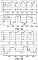
- Fig. 5 illustrates screen shots showing acceleration and altimeter signals during stand-sit transitions from a test where a subject wore a sensing device at four different locations of the body.
- Figs. 5A to 5D illustrate motion signals 52 (top) and altimeter signals 53 (bottom) measured during consecutive stand-sit transitions.
- the altimeter signal (bottom) was first processed with a median filter to remove high frequency spikes without sacrificing the sharp stand-sit transition edges, additionally the DC wander caused by the slow ambient pressure changes (due to the weather) gets removed as well.
- Fig. 5A illustrates the signals of the sensing device positioned at the chest
- Fig. 5B illustrates the signals of the sensing device positioned at the hip
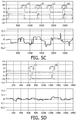
- Fig. 5C illustrates the signals of the sensing device positioned at the thigh
- Fig. 5D illustrates the signals of the sensing device positioned at the knee.
- the motion detection block 42 monitors the motion signal and the height signal, and once the desired motion type is detected, parameters or signal features are extracted from the signals by the feature extraction block 43.
- signal features parameters
- Examples of signal features (parameters) that may be extracted when the desired motion is a stand-sit/sit-stand transition include, but are not limited to, such features as:
- the classification is based on the height change and the orientation change as define above.
- Fig. 6 illustrates a plot of parameters extracted from the motion signal and from the height signal in a joint feature space.
- the plot is in the form of a scatter plot of the height change and the orientation change, with the orientation change in degrees along the horizontal axis and height change in meters along the vertical axis.
- Each point corresponds to one stand-sit transition; plus indicates chest points 60; diamond indicates hip points 61; triangle indicates thigh points 62; and circle indicates knee points 63. It can be seen that with the orientation change only, thigh points 62 would be difficult to distinguish from knee points 63, whereas with the height change only, the cluster of chest points 60 overlaps with that of hip points 61. In the joint feature space, however, the four clusters are very well separated.
- a classifier such as a decision tree, can be implemented to detect the correct sensor position based on the extracted parameters from the motion signal and the height signal.
- a classification algorithm may access a database of predefined signal features associated with related wearing positions, and base the classification on a comparison between the predefined signal features of the database and the one or more parameters extracted from the motion signal and the height signal to determine the wearing position of the sensing device.
- an initial wearing position may be accessed from a set of possible wearing positions and compared with the detected wearing position.
- the initial wearing position may in an embodiment be the last detected wearing position, it may be a random guess, it may be detected from preliminary signal analysis, or from other means. If the detected wearing position matches the initial wearing position the detected wearing position is maintained, otherwise a new initial wearing position from the set of possible wearing positions is selected and the new wearing position is detected, and the new initial wearing position and the new detected wearing positions are compared.
- the hypotheses-confirmation structure is implemented as schematically depicted in Fig. 7 .
- the blocks 70-73 each determines a sit-stand transition with an initial assumption of the wearing location. More or less blocks are possible depending on the number of possible wearing locations supported by the device.
- Each of the blocks embody a motion detection block 42 as depicted in Fig. 4 , however implemented with a motion detection algorithm detecting a specific type of movement with an assumed device wearing location.
- the output of these blocks 74 will be a yes or a no. That it, the algorithm used for detecting a sit-stand transition assumes an initial wearing location and monitors the motion signal and/or the height signal until a sit-stand transition is detected.
- the initial guess may be a sit-to-stand transition with chest location 70. If a sit-to-stand transition is detected (output 74 is yes), the block 75 will perform the above-described method for wearing location detection. That is, block 75 implements the feature extraction block 43 and the classification block 44 as depicted in Fig. 4 . However, the calculation of the wearing location is only initiated upon a "yes" output 74. The calculation itself does not use the assumed locations, and it simply extracts the parameters to be used for the detection and runs the classification based on these parameters. The block 76 checks whether or not the output of block 75 confirms the assumption of the initial wearing location in the sit-stand detection block 70.
- a high probability can be assumed for the wearing location result, if not a low probability can be assumed.
- the calculated wearing location is assumed, otherwise the result is ignored.
- a new initial guess 77 e.g. hip location 71
- the confirmation method is repeated until a confirmed location is achieved; or in the event, that no confirmation is achieved when having tried all four options, then the segment of data is ignored and the method is repeated with the next segment of the data.
- a new initial guess may also be made if for example too long time is spent in order to detect a specific movement such as a sit-stand transition.
- the blocks 70-73 may be run on any candidate segment for this selected type of movement in the sensing data, sequentially.
- the motion is detected and confirmation is obtained on sensor location, and thus there is no need to run the rest of the blocks if any.
- the motion is not detected, and in the third the motion is detected but no confirmation is obtained with all four blocks having been executed. For all these situations, the algorithm moves to the next candidate segment of the preselected type of movement.
- decision fusion methods can be applied upon the detection over longer times.
- intermediate decisions on the wearing position are made, each based on one stand-sit transition.
- the ultimate decision is then made by means of a certain decision fusion method. For instance, with majority voting, a sensor position appearing most often among the accumulated intermediate decisions wins.
- a more accurate location indication can be achieved when more information is available to the algorithm, like the body length, limb lengths, and chair heights in the case where a sit-stand transition is targeted.
- Application of a wearing location detection algorithm would be improved by normalization of the detected height change using the body length.
- the invention can be implemented in any suitable form including hardware, software, firmware or any combination of these.
- the invention or some features of the invention can be implemented as computer software running on one or more data processors and/or digital signal processors.
- the elements and components of an embodiment of the invention may be physically, functionally and logically implemented in any suitable way. Indeed, the functionality may be implemented in a single unit, in a plurality of units or as part of other functional units. As such, the invention may be implemented in a single unit, or may be physically and functionally distributed between different units and processors.
Landscapes
- Health & Medical Sciences (AREA)
- Life Sciences & Earth Sciences (AREA)
- Engineering & Computer Science (AREA)
- Heart & Thoracic Surgery (AREA)
- Public Health (AREA)
- Veterinary Medicine (AREA)
- Biophysics (AREA)
- Pathology (AREA)
- Physics & Mathematics (AREA)
- Biomedical Technology (AREA)
- General Health & Medical Sciences (AREA)
- Medical Informatics (AREA)
- Molecular Biology (AREA)
- Surgery (AREA)
- Animal Behavior & Ethology (AREA)
- Physiology (AREA)
- Dentistry (AREA)
- Oral & Maxillofacial Surgery (AREA)
- Human Computer Interaction (AREA)
- Measurement Of The Respiration, Hearing Ability, Form, And Blood Characteristics Of Living Organisms (AREA)
- Radar Systems Or Details Thereof (AREA)
- Measurement Of Velocity Or Position Using Acoustic Or Ultrasonic Waves (AREA)
- Position Fixing By Use Of Radio Waves (AREA)
Description
- The invention relates to a sensing device for detecting the wearing position of the device with respect to a user.
-
US 2008/0190202 discloses a motion sensing apparatus generally comprising a housing unit operable to be attached to an object at an attachment position, an accelerometer operable to provide a signal corresponding to an acceleration measurement: and a processing system. The processing system is operable to acquire the signal corresponding to the acceleration measurement and analyze the acquired acceleration measurement to identify the attachment position of the housing unit. - In recent years, on-body sensing has been made possible due to the technological progress within sensor miniaturization, energy saving and wireless communications. A sensing device in the form of a body-worn accelerometer-based activity monitor (AM) is able to record motion-induced acceleration signals. From such acceleration signals, activity-context information, such as physical activity related energy expenditure (AEE), activity type and durations can be extracted. In healthcare applications, the activity-context information helps to correctly interpret patients' vital body signals, such as ECG and respiration rate, and to improve the diagnosis. In consumer lifestyle applications, it enables users to maintain a healthy physical activity level, thus avoiding inactivity-related diseases.
- To translate the acceleration data into an AEE value with a required accuracy or to be able to provide correct activity type recognition, it may be crucial to have prior knowledge of the sensor's location. The article: "Detection of Sensor Wearing Positions for Accelerometry-based Daily Activity Assessment", The Sixth IASTED International Conference on Biomedical Engineering, Feb. 2008 by Yin and Goris, discloses a method of detecting a sensor wearing position based on comparing body position dependent features that are extracted from measured acceleration data with features of an established feature database.
-
Fig. 1 is adapted from the mentioned article by Yin and Goris and shows an example of correlation between the acceleration power accumulated in the form of total accelerations pr. day (y axis) and the corresponding physical activity level measured with a doubly-labeled water method (x axis). Thecorrelation curves experimental data waist 1, 4 (diamond),wrist 2, 5 (square) andbra 3, 6 (triangle). Thus even though the readout data relate to the same activities, the determined physical activity level differ according to the attachment position of the accelerometer. - Hence, there is the need in the art for accurately detecting the wearing position of an on-body sensing device.
- It is an object of the present invention to provide a flexible on-body sensing device which can be worn at a number of body position while nevertheless accurately can detect the wearing position of the device itself irrespectively of the wearing position. Moreover it is a further object of the present to provide an on-body sensing device which is able to extract the wearing location with a very limited number of user-device interactions, and even with no need of any intervention from the user during any type of activity, so as to provide a fully automatic sensing device for detecting the wearing position.
- The invention preferably seeks to mitigate, alleviate or eliminate one or more of the disadvantages of the prior art singly or in any combination. The invention is defined by the independent claims. The dependent claims define advantageous embodiments.
- In accordance with a first aspect, there is provided a sensing device for detecting a wearing position of a sensing device with respect to a user, the device comprising:
- a motion sensor for detecting a motion signal;
- a height sensor for detecting a height signal, the height signal being measured based on an air pressure signal; and
- a computing unit to which the motion sensor and the height sensor are communicatively connected,
- recognize a preselected type of a motion in the motion signal and in the height signal, and
- when a motion of the preselected type has been detected in the motion signal and in the height signal, determine the wearing position from one or more parameters extracted from the motion signal and the height signal measured during the occurrence of the motion of the preselected type.
- The inventors of the present invention have realized that in order to detect the correct wearing position with a high certainty, it is important to base the decision on more than one input signal, and where the input signals behave differently during a specific movement of the user when the sensing device is attached to different body parts. A signal related to a motion of the user and a signal related to the height of the sensor fulfill this requirement. By basing the detection of the wearing position on a motion signal and a height signal, a sensing device which accurately can determine the wearing position solely based on the detected signals and which does not require, or which does only require few, user inputs may thereby be provided. Embodiments of the present invention may therefore provide a sensing device which automatically detects the wearing position of the device. It is advantageous to recognize the type of motion in the detected signals since the accuracy of the detection of the wearing position can be improved by basing the detection of the wearing position on a specific type of movement of the user wearing the sensing device.
- In advantageous embodiments of the present invention, to recognize a preselected type of a motion in the motion signal and/or in the height signal, it suffices to at least recognize a candidate segment of data representing the preselected type of a motion in the signals. The computing unit is then further adapted to detect that a candidate segment of data of the preselected type of motion is present in the motion signal and in the height signal.
- In advantageous embodiments of the present invention, the computing unit is further adapted to extract one or more parameters from the motion signal and the height signal measured during the occurrence of the motion of the preselected type, and basing the determination of the wearing position on such parameters. It is convenient to base a computational decision process on extracted parameter values and/or ranges.
- In advantageous embodiments of the present invention, the detection of the wearing position is based on a classification algorithm. Classification algorithms are well-suited in connection with computational decision making based on complex input signals.
- In a second aspect, the invention relates to a method of detecting a wearing position of a sensing device, where the detection of a wearing position with respect to a user is based on a detected motion signal and a detected height signal.
- In a third aspect, the invention relates a computer program product adapted to carry out the method of the second aspect. The computer program product may be implemented into a computing unit of the sensing device to render the device the functionality of the second aspect of the present invention.
- In general the various aspects of the invention may be combined and coupled in any way possible within the scope of the invention. These and other aspects, features and/or advantages of the invention will be apparent from and elucidated with reference to the embodiments described hereinafter.
- Embodiments of the invention will be described, by way of example only, with reference to the drawings, in which
-
Fig. 1 shows a graph of accumulated acceleration power based on accelerometer data and the corresponding physical activity level based on the doubly-labeled water method; -
Fig. 2 illustrates an embodiment of a sensing device for detecting a wearing position; -
Fig. 3 illustrates examples of attachment positions of the sensing device; -
Fig. 4 illustrates a block diagram of an embodiment of an algorithm for detecting the wearing position of the sensing device; -
Figs. 5A-D illustrate screen shots showing acceleration and altimeter signals during stand-sit transitions; -
Fig. 6 illustrates a scatter plot of parameters extracted from the motion signal and from the height signal; and -
Fig. 7 illustrates a block diagram of an embodiment of an algorithm for implementing a hypotheses-confirmation structure in the scheme for detecting the wearing position. - Embodiments of the present invention relates to a sensing device for detecting a wearing position of the device. The sensing device may be part of a host device with a given functionality where the wearing position of the device is needed for improved operation. Such devices include, but are not limited to, activity sensors and fall detectors.
-
Fig. 1 as already discussed in the section Background of the Invention, illustrates that calculated activity levels may be dependent upon the assumed wearing position of the activity sensor. Not using the correct wearing position when converting detected movements into a physical activity level may thereby introduce uncertainty in the calculated activity level. In connection with fall detection it is also important to know the correct wearing position. The algorithm used for detecting a fall uses the wearing position together with the detected movement to determine whether or not the detected movement was related to a fall or not. In fall detection is it important to have as low a false alarm rate as possible while not missing any falls that actually happened, and therefore it is important to know the correct wearing position. -
Fig. 2 illustrates an embodiment of asensing device 20 for detecting a wearing position. The device comprises amotion sensor 21 for detecting a motion signal. The motion sensor is typically a tri-axial accelerometer. The device further comprises aheight sensor 22 for detecting a height signal of the sensor location. The height sensor may be an altimeter or a barometer based on measuring an air pressure signal or difference in air pressure. The device further comprises acomputing unit 23. The computing unit is connected to the motion sensor and the height sensor for accessing or reading the motion signal and the height signal. Based on the inputs from the motion sensor and height sensor, the computing unit determines the wearing position of the sensing device with respect to a user. - The two sensors are placed very close in the housing so that they measure signals related to movement of the same body part. For example, if the sensing device is attached to the knee, the two sensors should be placed so close that the detected movement is related to the movement of the knee alone and not from movement of adjacent limbs. Thus the proximity of the two sensors should be closer for knee attachment than for chest attachment. To have the freedom of attachment to different body parts, the two sensors should be placed so that the detecting area of the motion sensor and the detecting area of the height sensor are located less than five centimeters from each other. They may also be collocated, located adjacently or fixed to each other.
- In an embodiment, the
motion sensor 21 measures both inertial accelerations caused by the body movements and gravitational accelerations imposed by the earth's gravity. The height (e.g., pressure)sensor 22 makes use of the air pressure variation when it moves vertically to provide information about altitude change. In an embodiment, the pressure sensor may be calibrated, for instance by setting a reference altitude as the reference level. The air pressure sensor may then measure height or height change with regard to this reference level. - The device is typically made integral with a
host device 24, the host device may comprise additional components to the ones shown inFig. 2 . For example, the host device may comprise connector jacks for connection to peripheral equipment, such as connection to an external computing device. The host device may also comprise a display for display of activity level, etc. In embodiments the sensing device and the host device may share components, such as the accelerometer and the height sensor, which may additionally be used for calculating an activity level or other parameters. Likewise the computing unit may be shared between the host device and the sensing device. - For the recognition of common physical activity types, such as walking, running, cycling, and the assessment of the related energy expenditure, it is desirable to wear the sensing device close to the body trunk instead of extremities like ankle and wrist so that the whole body movement gets recorded.
Fig. 3 illustrates examples of attachment positions of the sensing device in this regard. For example the sensing device may be attached at thechest 30, e.g. as a pendant around the neck or attached to a bra; at thehip 31, e.g. clipped to a belt; at thethigh 32, e.g. in the pocket of the trousers; at theknee 33, e.g. by use of a strap. Body positions are not limited to above-mentioned ones, and these are only shown as examples. Moreover, the illustration of several sensing devices 30-33 is not to be interpreted as more than one sensing device is used. In test situations several sensing devices may be attached to one person, however in a typical situation of use, only a single sensing device is used. -
Fig. 4 illustrates a block diagram of an embodiment of an algorithm for detecting the wearing position of the sensing device. Themotion signal 40 andheight signal 41 are input into a motion detection unit or block 42 implemented in the computing unit of the sensing device. Themotion detection block 42 detects the occurrence of a signal transition corresponding to a given type of motion of the user wearing the device, in the motion signal and in the height signal. The motion detection block thus seeks to recognize a specific preselected movement type of the user from one of, or both of, the input signals 40, 41. Once a given preselected type of motion has been recognized or detected, at least one parameter related to the motion signal during the occurrence of the motion of the preselected type is extracted from the motion signal and at least one parameter related to the height signal during the occurrence of the motion of the preselected type is extracted from the height signal in afeature extraction block 43. The extracted parameters are input into aclassification block 44 for, based on a classification algorithm, detecting the wearingposition 45. - In an embodiment, the computing unit is adapted to monitor the motion signal and/or the height signal to recognize a given or preselected type of motion and to detect that a signal transition corresponding to this given type of motion in the motion signal and/or in the height signal has occurred. The shape of the signal transition is related to a specific movement of the body. In connection with
Figs. 5-7 the signal transition related to a sit-stand movement is used, however other types of movements and related signal transitions can be used as well, such as signal transitions related to walking, to jumping, etc. The recognition of a specific motion can be realized using a stand-alone activity classifier based on both acceleration and altimeter data. In addition, the context of the occurrence of the motion can be used in connection with the recognition. For example, the acceleration data provide both movement (e.g. walking or cycling) and posture (e.g. standing or lying) information of the relevant body part. -
Fig. 5 illustrates screen shots showing acceleration and altimeter signals during stand-sit transitions from a test where a subject wore a sensing device at four different locations of the body. -
Figs. 5A to 5D illustrate motion signals 52 (top) and altimeter signals 53 (bottom) measured during consecutive stand-sit transitions. In the plots of the motion signals, the readout from three sensing axes of a tri-axial accelerometer are shown, and stand-to-sit and sit-to-stand transitions are indicated withreference numeral 50 andreference numeral 51 respectively. The altimeter signal (bottom) was first processed with a median filter to remove high frequency spikes without sacrificing the sharp stand-sit transition edges, additionally the DC wander caused by the slow ambient pressure changes (due to the weather) gets removed as well.Fig. 5A illustrates the signals of the sensing device positioned at the chest;Fig. 5B illustrates the signals of the sensing device positioned at the hip;Fig. 5C illustrates the signals of the sensing device positioned at the thigh; andFig. 5D illustrates the signals of the sensing device positioned at the knee. - Referring back to
Fig. 4 , themotion detection block 42 monitors the motion signal and the height signal, and once the desired motion type is detected, parameters or signal features are extracted from the signals by thefeature extraction block 43. Examples of signal features (parameters) that may be extracted when the desired motion is a stand-sit/sit-stand transition include, but are not limited to, such features as: - 1) height change around a transition;
- 2) orientation change around a transition;
- 3) acceleration energy around transition;
- 4) sensor trajectory around transition;
- 5) difference in height change between stand-to-sit and sit-to-stand transitions;
- 6) difference in orientation change between stand-to-sit and sit-to-stand transitions.
- More specifically, the signal feature reflecting the height change may be defined as:

- The orientation change may be defined as the angle θ that the gravitational vector a (g) rotates during a stand-sit transition, calculated as:

- Other forms reflecting the difference of two vectors can be also considered, such as the Euclidean distance:

- The extraction of features and thereafter the realization of the sensor position detection are dealt with by the sensor positioning classification block 44 (cf.
Fig. 4 ). In an embodiment, the classification is based on the height change and the orientation change as define above. -
Fig. 6 illustrates a plot of parameters extracted from the motion signal and from the height signal in a joint feature space. The plot is in the form of a scatter plot of the height change and the orientation change, with the orientation change in degrees along the horizontal axis and height change in meters along the vertical axis. Each point corresponds to one stand-sit transition; plus indicates chest points 60; diamond indicates hip points 61; triangle indicates thigh points 62; and circle indicates knee points 63. It can be seen that with the orientation change only, thigh points 62 would be difficult to distinguish from knee points 63, whereas with the height change only, the cluster of chest points 60 overlaps with that of hip points 61. In the joint feature space, however, the four clusters are very well separated. - A classifier, such as a decision tree, can be implemented to detect the correct sensor position based on the extracted parameters from the motion signal and the height signal. To obtain a classification algorithm to be used in practical situations, more stand-sit transitions than the ones shown in
Fig. 6 need to be collected to establish a sizeable training set. To get good statistics, these transitions are preferably recorded with different sensor wearing positions and cover a wide demographic range of relevant subjects. The classification algorithm may access a database of predefined signal features associated with related wearing positions, and base the classification on a comparison between the predefined signal features of the database and the one or more parameters extracted from the motion signal and the height signal to determine the wearing position of the sensing device. - Dependent upon the specific type of algorithm used, the recognition of the type of the motion may require prior knowledge of a sensor wearing position. In an embodiment, a hypotheses-confirmation structure is implemented based on an initial guess and subsequent confirmation of the guess. In this regard, an initial wearing position may be accessed from a set of possible wearing positions and compared with the detected wearing position. The initial wearing position may in an embodiment be the last detected wearing position, it may be a random guess, it may be detected from preliminary signal analysis, or from other means. If the detected wearing position matches the initial wearing position the detected wearing position is maintained, otherwise a new initial wearing position from the set of possible wearing positions is selected and the new wearing position is detected, and the new initial wearing position and the new detected wearing positions are compared.
- In an embodiment, the hypotheses-confirmation structure is implemented as schematically depicted in
Fig. 7 . The blocks 70-73 each determines a sit-stand transition with an initial assumption of the wearing location. More or less blocks are possible depending on the number of possible wearing locations supported by the device. Each of the blocks embody amotion detection block 42 as depicted inFig. 4 , however implemented with a motion detection algorithm detecting a specific type of movement with an assumed device wearing location. The output of theseblocks 74 will be a yes or a no. That it, the algorithm used for detecting a sit-stand transition assumes an initial wearing location and monitors the motion signal and/or the height signal until a sit-stand transition is detected. - In an embodiment, the initial guess may be a sit-to-stand transition with
chest location 70. If a sit-to-stand transition is detected (output 74 is yes), theblock 75 will perform the above-described method for wearing location detection. That is, block 75 implements thefeature extraction block 43 and theclassification block 44 as depicted inFig. 4 . However, the calculation of the wearing location is only initiated upon a "yes"output 74. The calculation itself does not use the assumed locations, and it simply extracts the parameters to be used for the detection and runs the classification based on these parameters. Theblock 76 checks whether or not the output ofblock 75 confirms the assumption of the initial wearing location in the sit-stand detection block 70. If so, a high probability can be assumed for the wearing location result, if not a low probability can be assumed. When there is confirmation the calculated wearing location is assumed, otherwise the result is ignored. If the result is ignored, a new initial guess 77 (e.g. hip location 71) is assumed and the confirmation method is repeated until a confirmed location is achieved; or in the event, that no confirmation is achieved when having tried all four options, then the segment of data is ignored and the method is repeated with the next segment of the data. A new initial guess may also be made if for example too long time is spent in order to detect a specific movement such as a sit-stand transition. - Thus for a given or selected type of movement to be detected, the blocks 70-73 may be run on any candidate segment for this selected type of movement in the sensing data, sequentially. In a first situation, the motion is detected and confirmation is obtained on sensor location, and thus there is no need to run the rest of the blocks if any. In a second situation, the motion is not detected, and in the third the motion is detected but no confirmation is obtained with all four blocks having been executed. For all these situations, the algorithm moves to the next candidate segment of the preselected type of movement.
- To improve the detection accuracy further, decision fusion methods can be applied upon the detection over longer times. In this case, intermediate decisions on the wearing position are made, each based on one stand-sit transition. The ultimate decision is then made by means of a certain decision fusion method. For instance, with majority voting, a sensor position appearing most often among the accumulated intermediate decisions wins.
- It is envisioned that a more accurate location indication can be achieved when more information is available to the algorithm, like the body length, limb lengths, and chair heights in the case where a sit-stand transition is targeted. Application of a wearing location detection algorithm would be improved by normalization of the detected height change using the body length.
- The invention can be implemented in any suitable form including hardware, software, firmware or any combination of these. The invention or some features of the invention can be implemented as computer software running on one or more data processors and/or digital signal processors. The elements and components of an embodiment of the invention may be physically, functionally and logically implemented in any suitable way. Indeed, the functionality may be implemented in a single unit, in a plurality of units or as part of other functional units. As such, the invention may be implemented in a single unit, or may be physically and functionally distributed between different units and processors.
- Although the present invention has been described in connection with the specified embodiments, it is not intended to be limited to the specific form set forth herein. Rather, the scope of the present invention is limited only by the accompanying claims. In the claims, the term "comprising" does not exclude the presence of other elements or steps. Additionally, although individual features may be included in different claims, these may possibly be advantageously combined, and the inclusion in different claims does not imply that a combination of features is not feasible and/or advantageous. In addition, singular references do not exclude a plurality. Thus, references to "a", "an", "first", "second" etc. do not preclude a plurality. Furthermore, reference signs in the claims shall not be construed as limiting the scope.
Claims (9)
- A sensing device (20) for detecting a wearing position of the sensing device with respect to a user, the device comprising:- a motion sensor (21) for detecting a motion signal (52);- a height sensor (22) for detecting a height signal (53), the height signal being measured based on an air pressure signal; and- a computing unit (23) to which the motion sensor and the height sensor are communicatively connected,wherein the computing unit is adapted to- recognize a preselected type of a motion in the motion signal (52) and in the height signal (53), and- when the preselected type of the motion has been detected (50, 51) in the motion signal and in the height signal, determine the wearing position from one or more parameters (60-63) extracted from the motion signal and the height signal measured during the occurrence (50,51) of the preselected type of the motion.
- The sensing device according to claim 1, wherein the detecting area of the motion sensor and the detecting area of the height sensor are located less than five centimeters from each other.
- The sensing device according to claim 1, wherein the motion sensor is a tri-axial accelerometer.
- The sensing device according to claim 1, wherein the height sensor is an altimeter.
- The sensing device according to claim 1, wherein the computing unit is adapted to execute a classification algorithm, and where the classification algorithm is adapted to detect the wearing position, based on the one or more parameters extracted from the motion signal and the height signal measured during the occurrence of the motion of the preselected type.
- The sensing device according to claim 5, wherein the classification algorithm is adapted to access a database of predefined signal features, the predefined signal features being associated with related wearing positions, and wherein the classification algorithm is further adapted to perform a comparison between the predefined signal features and one or more parameters extracted from the motion signal and the height signal, so as to determine the wearing position of the sensing device.
- The sensing device according to claim 5, wherein the computing unit is further adapted to access an initial wearing position from a set of possible wearing positions, detecting the wearing position, and compare the detected wearing position to the initial wearing position, if the detected wearing position matches the initial wearing position, the detected wearing position is maintained, otherwise a new initial wearing position from the set of possible wearing positions is accessed and a new wearing position is detected, and the new initial wearing position and the new detected wearing positions are compared.
- A method of detecting a wearing position of a sensing device with respect to a user, the method comprising:- detecting, by a motion sensor of the sensing device, a motion signal;- detecting, by a height sensor of the sensing device, a height signal, the height signal being measured based on an air pressure signal;wherein the method comprises further steps of:- recognizing, by a computing unit of the sensing device, a preselected type of a motion in the motion signal (52) and in the height signal (53), and- when the preselected type of the motion has been detected (50, 51) in the motion signal and in the height signal, determining, by the computing unit of the sensing device, the wearing position from one or more parameters (60-63) extracted from the motion signal and the height signal measured during the occurrence (50, 51) of the preselected type of the motion.
- A computer program product comprising software code adapted to cause the sensing device of claim 1 to carry out the method according to claim 8 when executed on the computing unit of the sensing device.
Priority Applications (1)
| Application Number | Priority Date | Filing Date | Title |
|---|---|---|---|
| EP10726268.5A EP2432392B1 (en) | 2009-05-20 | 2010-05-17 | Sensing device for detecting a wearing position |
Applications Claiming Priority (3)
| Application Number | Priority Date | Filing Date | Title |
|---|---|---|---|
| EP09160729 | 2009-05-20 | ||
| PCT/IB2010/052163 WO2010134010A1 (en) | 2009-05-20 | 2010-05-17 | Sensing device for detecting a wearing position |
| EP10726268.5A EP2432392B1 (en) | 2009-05-20 | 2010-05-17 | Sensing device for detecting a wearing position |
Publications (2)
| Publication Number | Publication Date |
|---|---|
| EP2432392A1 EP2432392A1 (en) | 2012-03-28 |
| EP2432392B1 true EP2432392B1 (en) | 2017-03-08 |
Family
ID=42556436
Family Applications (1)
| Application Number | Title | Priority Date | Filing Date |
|---|---|---|---|
| EP10726268.5A Active EP2432392B1 (en) | 2009-05-20 | 2010-05-17 | Sensing device for detecting a wearing position |
Country Status (8)
| Country | Link |
|---|---|
| US (1) | US9119568B2 (en) |
| EP (1) | EP2432392B1 (en) |
| JP (1) | JP5674766B2 (en) |
| CN (1) | CN102427765B (en) |
| AU (1) | AU2010250785B2 (en) |
| BR (1) | BRPI1007685A2 (en) |
| ES (1) | ES2626909T3 (en) |
| WO (1) | WO2010134010A1 (en) |
Cited By (1)
| Publication number | Priority date | Publication date | Assignee | Title |
|---|---|---|---|---|
| EP3657456A1 (en) | 2018-11-26 | 2020-05-27 | Koninklijke Philips N.V. | A method and system for monitoring a user |
Families Citing this family (39)
| Publication number | Priority date | Publication date | Assignee | Title |
|---|---|---|---|---|
| US9489815B2 (en) * | 2011-04-29 | 2016-11-08 | Koninklijke Philips N.V. | Apparatus for use in a fall detector or fall detection system, and a method of operating the same |
| US10145707B2 (en) * | 2011-05-25 | 2018-12-04 | CSR Technology Holdings Inc. | Hierarchical context detection method to determine location of a mobile device on a person's body |
| EP2549228A1 (en) | 2011-07-20 | 2013-01-23 | Koninklijke Philips Electronics N.V. | A method of enhancing the detectability of a height change with an air pressure sensor and a sensor unit for determining a height change |
| US9524424B2 (en) | 2011-09-01 | 2016-12-20 | Care Innovations, Llc | Calculation of minimum ground clearance using body worn sensors |
| US20140313030A1 (en) * | 2011-09-02 | 2014-10-23 | Koninklijke Philips N.V. | Bed exit monitoring apparatus |
| US9165113B2 (en) * | 2011-10-27 | 2015-10-20 | Intel-Ge Care Innovations Llc | System and method for quantitative assessment of frailty |
| US9877667B2 (en) | 2012-09-12 | 2018-01-30 | Care Innovations, Llc | Method for quantifying the risk of falling of an elderly adult using an instrumented version of the FTSS test |
| US9486070B2 (en) | 2012-10-10 | 2016-11-08 | Stirworks Inc. | Height-adjustable support surface and system for encouraging human movement and promoting wellness |
| US10038952B2 (en) | 2014-02-04 | 2018-07-31 | Steelcase Inc. | Sound management systems for improving workplace efficiency |
| US10827829B1 (en) | 2012-10-10 | 2020-11-10 | Steelcase Inc. | Height adjustable support surface and system for encouraging human movement and promoting wellness |
| US10085562B1 (en) | 2016-10-17 | 2018-10-02 | Steelcase Inc. | Ergonomic seating system, tilt-lock control and remote powering method and appartus |
| JP6444309B2 (en) * | 2012-11-30 | 2018-12-26 | コーニンクレッカ フィリップス エヌ ヴェKoninklijke Philips N.V. | Method and apparatus for identifying transitions between sitting and standing positions |
| JP2014161514A (en) * | 2013-02-25 | 2014-09-08 | Nintendo Co Ltd | Information processing system, information processing program, information processing device and information processing method |
| US9750433B2 (en) | 2013-05-28 | 2017-09-05 | Lark Technologies, Inc. | Using health monitor data to detect macro and micro habits with a behavioral model |
| WO2014210210A1 (en) * | 2013-06-25 | 2014-12-31 | Lark Technologies, Inc. | Method for classifying user motion |
| WO2014208814A1 (en) * | 2013-06-26 | 2014-12-31 | 주식회사 엔젤윙즈 | Automatic excrement processing device |
| JP6136806B2 (en) * | 2013-09-20 | 2017-05-31 | カシオ計算機株式会社 | Physical information acquisition device, physical information acquisition method, physical information acquisition program |
| US20150127298A1 (en) * | 2013-11-04 | 2015-05-07 | Invensense, Inc. | Activity detection and analytics |
| EP3089662B1 (en) * | 2013-12-31 | 2022-12-21 | Lifescan, Inc. | Methods, systems, and devices for optimal positioning of sensors |
| CN103892815B (en) * | 2014-04-28 | 2016-02-17 | 广东欧珀移动通信有限公司 | A kind of Human Physiology Monitoring Indexes method and monitoring system |
| CN103942456B (en) * | 2014-05-08 | 2017-05-10 | 北京睿仁医疗科技有限公司 | Measuring method and device capable of automatically judging wear position |
| US9497592B2 (en) | 2014-07-03 | 2016-11-15 | Qualcomm Incorporated | Techniques for determining movements based on sensor measurements from a plurality of mobile devices co-located with a person |
| US10952647B2 (en) * | 2015-02-23 | 2021-03-23 | Sony Corporation | Sensor device, sensing method, and information processing device |
| TWI572228B (en) * | 2015-03-05 | 2017-02-21 | 宏達國際電子股份有限公司 | Mobile device and method for executing a function thereof |
| KR102318887B1 (en) * | 2015-03-06 | 2021-10-29 | 삼성전자주식회사 | Wearable electronic device and method for controlling thereof |
| CA2996196A1 (en) | 2015-08-31 | 2017-03-09 | Masimo Corporation | Wireless patient monitoring systems and methods |
| CN105797348B (en) * | 2016-03-09 | 2019-04-05 | 成都艾德沃传感技术有限公司 | A kind of method and wearable electronic equipment of detection object type of sports |
| JP6698997B2 (en) * | 2016-04-12 | 2020-05-27 | 株式会社アコーズ | Activity meter |
| WO2017191036A1 (en) | 2016-05-04 | 2017-11-09 | Koninklijke Philips N.V. | A method and apparatus for determining at least one of a position and an orientation of a wearable device on a subject |
| US9921726B1 (en) | 2016-06-03 | 2018-03-20 | Steelcase Inc. | Smart workstation method and system |
| CN106370180B (en) * | 2016-08-29 | 2019-06-04 | 常州市钱璟康复股份有限公司 | Inertial sensor initial position recognition methods based on dynamic time warping algorithm |
| CN108937914A (en) * | 2018-07-20 | 2018-12-07 | 广东乐心医疗电子股份有限公司 | Wearable device and physiological information monitoring method |
| US11678829B2 (en) | 2019-04-17 | 2023-06-20 | Masimo Corporation | Physiological monitoring device attachment assembly |
| USD919094S1 (en) | 2019-08-16 | 2021-05-11 | Masimo Corporation | Blood pressure device |
| USD985498S1 (en) | 2019-08-16 | 2023-05-09 | Masimo Corporation | Connector |
| USD917704S1 (en) | 2019-08-16 | 2021-04-27 | Masimo Corporation | Patient monitor |
| USD927699S1 (en) | 2019-10-18 | 2021-08-10 | Masimo Corporation | Electrode pad |
| USD933232S1 (en) | 2020-05-11 | 2021-10-12 | Masimo Corporation | Blood pressure monitor |
| CN116649959A (en) * | 2023-05-31 | 2023-08-29 | 北京欧应科技有限公司 | Monitoring system, method for judging positioning of wearing device and storage medium |
Citations (7)
| Publication number | Priority date | Publication date | Assignee | Title |
|---|---|---|---|---|
| WO2004114245A1 (en) | 2003-06-25 | 2004-12-29 | Ist International Security Technology Oy | A device for indicating a fall |
| US20050033200A1 (en) | 2003-08-05 | 2005-02-10 | Soehren Wayne A. | Human motion identification and measurement system and method |
| US20080105065A1 (en) | 2006-10-31 | 2008-05-08 | Samsung Electronics Co., Ltd. | Movement distance measuring apparatus and method |
| US20080254944A1 (en) | 2007-04-14 | 2008-10-16 | Muri John I | Monitoring of a Wearable Athletic Device |
| US7450002B2 (en) | 2005-01-14 | 2008-11-11 | Samsung Electronics Co., Ltd. | Method and apparatus for monitoring human activity pattern |
| DE102007052588A1 (en) | 2007-11-03 | 2009-05-07 | Töteberg, Andreas | Person e.g. forest worker, monitoring system, has microprocessor comparing air-pressure with characteristic diagram and releasing alarm to device e.g. mobile phone, corresponding to detection of downfall of person |
| US8773269B2 (en) | 2008-06-27 | 2014-07-08 | Neal T. RICHARDSON | Autonomous fall monitor |
Family Cites Families (13)
| Publication number | Priority date | Publication date | Assignee | Title |
|---|---|---|---|---|
| US8019A (en) * | 1851-04-01 | Improvement in machines for cutting screws on bedstead-rails | ||
| US7386401B2 (en) * | 1994-11-21 | 2008-06-10 | Phatrat Technology, Llc | Helmet that reports impact information, and associated methods |
| DE69736622T2 (en) * | 1996-07-03 | 2007-09-13 | Hitachi, Ltd. | Motion detection system |
| EP1366712A4 (en) * | 2001-03-06 | 2006-05-31 | Microstone Co Ltd | Body motion detector |
| JP4130739B2 (en) * | 2002-01-28 | 2008-08-06 | 本田技研工業株式会社 | Method for estimating floor reaction force of bipedal moving objects |
| JP2003323502A (en) * | 2002-05-07 | 2003-11-14 | Casio Comput Co Ltd | Action recording device and action recording program |
| US20050054938A1 (en) | 2003-07-29 | 2005-03-10 | Wehman Thomas C. | Method and apparatus including altimeter and accelerometers for determining work performed by an individual |
| JP5028751B2 (en) | 2005-06-09 | 2012-09-19 | ソニー株式会社 | Action recognition device |
| US8055469B2 (en) * | 2006-03-03 | 2011-11-08 | Garmin Switzerland Gmbh | Method and apparatus for determining the attachment position of a motion sensing apparatus |
| US7467060B2 (en) * | 2006-03-03 | 2008-12-16 | Garmin Ltd. | Method and apparatus for estimating a motion parameter |
| US7561960B2 (en) * | 2006-04-20 | 2009-07-14 | Honeywell International Inc. | Motion classification methods for personal navigation |
| FI120133B (en) * | 2006-05-29 | 2009-07-15 | Polar Electro Oy | A wrist unit and a method for determining motion information |
| KR101283464B1 (en) * | 2009-09-29 | 2013-07-12 | 한국전자통신연구원 | Motion recognition system using footwear for motion recognition |
-
2010
- 2010-05-17 BR BRPI1007685A patent/BRPI1007685A2/en not_active IP Right Cessation
- 2010-05-17 US US13/320,818 patent/US9119568B2/en active Active
- 2010-05-17 ES ES10726268.5T patent/ES2626909T3/en active Active
- 2010-05-17 AU AU2010250785A patent/AU2010250785B2/en not_active Ceased
- 2010-05-17 JP JP2012511386A patent/JP5674766B2/en not_active Expired - Fee Related
- 2010-05-17 CN CN201080021911.2A patent/CN102427765B/en not_active Expired - Fee Related
- 2010-05-17 EP EP10726268.5A patent/EP2432392B1/en active Active
- 2010-05-17 WO PCT/IB2010/052163 patent/WO2010134010A1/en active Application Filing
Patent Citations (7)
| Publication number | Priority date | Publication date | Assignee | Title |
|---|---|---|---|---|
| WO2004114245A1 (en) | 2003-06-25 | 2004-12-29 | Ist International Security Technology Oy | A device for indicating a fall |
| US20050033200A1 (en) | 2003-08-05 | 2005-02-10 | Soehren Wayne A. | Human motion identification and measurement system and method |
| US7450002B2 (en) | 2005-01-14 | 2008-11-11 | Samsung Electronics Co., Ltd. | Method and apparatus for monitoring human activity pattern |
| US20080105065A1 (en) | 2006-10-31 | 2008-05-08 | Samsung Electronics Co., Ltd. | Movement distance measuring apparatus and method |
| US20080254944A1 (en) | 2007-04-14 | 2008-10-16 | Muri John I | Monitoring of a Wearable Athletic Device |
| DE102007052588A1 (en) | 2007-11-03 | 2009-05-07 | Töteberg, Andreas | Person e.g. forest worker, monitoring system, has microprocessor comparing air-pressure with characteristic diagram and releasing alarm to device e.g. mobile phone, corresponding to detection of downfall of person |
| US8773269B2 (en) | 2008-06-27 | 2014-07-08 | Neal T. RICHARDSON | Autonomous fall monitor |
Non-Patent Citations (2)
| Title |
|---|
| BIN YIN ET AL.: "Detection of sensor wearing positions for accelerometry-based daily activity assessment", PROCEEDINGS OF THE SIXTH IASTED INTERNATIONAL CONFERENCE ON BIOMEDICAL ENGINEERING, 1 January 2008 (2008-01-01), INNSBRUCK, AUSTRIA, pages 390 - 395, XP009134172, ISBN: 978-0-88986-721 -5 |
| HENDRIK J LUINGE ET AL.: "Drift-free dynamic height sensor using MEMS IMU aided by MEMS pressure sensor", April 2008 (2008-04-01), XP031247847 |
Cited By (2)
| Publication number | Priority date | Publication date | Assignee | Title |
|---|---|---|---|---|
| EP3657456A1 (en) | 2018-11-26 | 2020-05-27 | Koninklijke Philips N.V. | A method and system for monitoring a user |
| WO2020109059A1 (en) | 2018-11-26 | 2020-06-04 | Koninklijke Philips N.V. | A method and system for monitoring a user |
Also Published As
| Publication number | Publication date |
|---|---|
| WO2010134010A1 (en) | 2010-11-25 |
| CN102427765A (en) | 2012-04-25 |
| AU2010250785B2 (en) | 2014-08-21 |
| ES2626909T3 (en) | 2017-07-26 |
| JP5674766B2 (en) | 2015-02-25 |
| US9119568B2 (en) | 2015-09-01 |
| JP2012527292A (en) | 2012-11-08 |
| US20120072168A1 (en) | 2012-03-22 |
| BRPI1007685A2 (en) | 2017-01-17 |
| CN102427765B (en) | 2014-12-17 |
| AU2010250785A1 (en) | 2012-01-19 |
| EP2432392A1 (en) | 2012-03-28 |
Similar Documents
| Publication | Publication Date | Title |
|---|---|---|
| EP2432392B1 (en) | Sensing device for detecting a wearing position | |
| Noor et al. | Adaptive sliding window segmentation for physical activity recognition using a single tri-axial accelerometer | |
| US10182746B1 (en) | Decoupling body movement features from sensor location | |
| EP3099229B1 (en) | Improvements in the detection of walking in measurements of the movement of a user | |
| EP3563764B1 (en) | Determining body postures and activities | |
| RU2637610C2 (en) | Monitoring device for physiological signal monitoring | |
| JP5874130B2 (en) | System and method for detecting human gait | |
| US20110246123A1 (en) | Personal status monitoring | |
| CN110313917B (en) | Fall-down sensing system and method using daily life movement as judgment reference | |
| US20190320944A1 (en) | Biomechanical activity monitoring | |
| WO2014153665A1 (en) | System and method for monitoring a subject | |
| Kwon et al. | An energy-efficient algorithm for classification of fall types using a wearable sensor | |
| Jovanov et al. | A mobile system for assessment of physiological response to posture transitions | |
| Jarchi et al. | Validation of the e-AR sensor for gait event detection using the parotec foot insole with application to post-operative recovery monitoring | |
| US10993640B2 (en) | System and method for monitoring the movement of a part of a human body | |
| US10980446B2 (en) | Apparatus and method for determining a sedentary state of a subject | |
| Pierleoni et al. | A versatile ankle-mounted fall detection device based on attitude heading systems | |
| US20210369138A1 (en) | System and method for detecting respiratory information using contact sensor | |
| EP3991157B1 (en) | Evaluating movement of a subject | |
| Alcaraz et al. | Mobile quantification and therapy course tracking for gait rehabilitation | |
| Weng et al. | Fall detection based on tilt angle and acceleration variations | |
| CN109692004B (en) | Method and device for detecting standing posture of human body | |
| Qin et al. | A smart phone based gait monitor system | |
| Farah et al. | Comparison of inertial sensor data from the wrist and mid-lower back during a 2-minute walk test | |
| EP3442403B1 (en) | Processing apparatus and method for determining an ambulation motion of a subject |
Legal Events
| Date | Code | Title | Description |
|---|---|---|---|
| PUAI | Public reference made under article 153(3) epc to a published international application that has entered the european phase |
Free format text: ORIGINAL CODE: 0009012 |
|
| 17P | Request for examination filed |
Effective date: 20111220 |
|
| AK | Designated contracting states |
Kind code of ref document: A1 Designated state(s): AL AT BE BG CH CY CZ DE DK EE ES FI FR GB GR HR HU IE IS IT LI LT LU LV MC MK MT NL NO PL PT RO SE SI SK SM TR |
|
| DAX | Request for extension of the european patent (deleted) | ||
| RAP1 | Party data changed (applicant data changed or rights of an application transferred) |
Owner name: KONINKLIJKE PHILIPS N.V. |
|
| 17Q | First examination report despatched |
Effective date: 20140304 |
|
| GRAP | Despatch of communication of intention to grant a patent |
Free format text: ORIGINAL CODE: EPIDOSNIGR1 |
|
| GRAJ | Information related to disapproval of communication of intention to grant by the applicant or resumption of examination proceedings by the epo deleted |
Free format text: ORIGINAL CODE: EPIDOSDIGR1 |
|
| INTG | Intention to grant announced |
Effective date: 20160810 |
|
| GRAP | Despatch of communication of intention to grant a patent |
Free format text: ORIGINAL CODE: EPIDOSNIGR1 |
|
| INTC | Intention to grant announced (deleted) | ||
| INTG | Intention to grant announced |
Effective date: 20160921 |
|
| RIN1 | Information on inventor provided before grant (corrected) |
Inventor name: DOORNBOS, RICHARD M. P. Inventor name: YIN, BIN |
|
| GRAS | Grant fee paid |
Free format text: ORIGINAL CODE: EPIDOSNIGR3 |
|
| GRAA | (expected) grant |
Free format text: ORIGINAL CODE: 0009210 |
|
| AK | Designated contracting states |
Kind code of ref document: B1 Designated state(s): AL AT BE BG CH CY CZ DE DK EE ES FI FR GB GR HR HU IE IS IT LI LT LU LV MC MK MT NL NO PL PT RO SE SI SK SM TR |
|
| REG | Reference to a national code |
Ref country code: GB Ref legal event code: FG4D |
|
| REG | Reference to a national code |
Ref country code: CH Ref legal event code: EP Ref country code: AT Ref legal event code: REF Ref document number: 872784 Country of ref document: AT Kind code of ref document: T Effective date: 20170315 |
|
| REG | Reference to a national code |
Ref country code: IE Ref legal event code: FG4D |
|
| REG | Reference to a national code |
Ref country code: DE Ref legal event code: R096 Ref document number: 602010040571 Country of ref document: DE |
|
| REG | Reference to a national code |
Ref country code: FR Ref legal event code: PLFP Year of fee payment: 8 |
|
| REG | Reference to a national code |
Ref country code: LT Ref legal event code: MG4D |
|
| REG | Reference to a national code |
Ref country code: NL Ref legal event code: MP Effective date: 20170308 |
|
| REG | Reference to a national code |
Ref country code: ES Ref legal event code: FG2A Ref document number: 2626909 Country of ref document: ES Kind code of ref document: T3 Effective date: 20170726 |
|
| PG25 | Lapsed in a contracting state [announced via postgrant information from national office to epo] |
Ref country code: NO Free format text: LAPSE BECAUSE OF FAILURE TO SUBMIT A TRANSLATION OF THE DESCRIPTION OR TO PAY THE FEE WITHIN THE PRESCRIBED TIME-LIMIT Effective date: 20170608 Ref country code: LT Free format text: LAPSE BECAUSE OF FAILURE TO SUBMIT A TRANSLATION OF THE DESCRIPTION OR TO PAY THE FEE WITHIN THE PRESCRIBED TIME-LIMIT Effective date: 20170308 Ref country code: FI Free format text: LAPSE BECAUSE OF FAILURE TO SUBMIT A TRANSLATION OF THE DESCRIPTION OR TO PAY THE FEE WITHIN THE PRESCRIBED TIME-LIMIT Effective date: 20170308 Ref country code: HR Free format text: LAPSE BECAUSE OF FAILURE TO SUBMIT A TRANSLATION OF THE DESCRIPTION OR TO PAY THE FEE WITHIN THE PRESCRIBED TIME-LIMIT Effective date: 20170308 Ref country code: GR Free format text: LAPSE BECAUSE OF FAILURE TO SUBMIT A TRANSLATION OF THE DESCRIPTION OR TO PAY THE FEE WITHIN THE PRESCRIBED TIME-LIMIT Effective date: 20170609 |
|
| REG | Reference to a national code |
Ref country code: AT Ref legal event code: MK05 Ref document number: 872784 Country of ref document: AT Kind code of ref document: T Effective date: 20170308 |
|
| PG25 | Lapsed in a contracting state [announced via postgrant information from national office to epo] |
Ref country code: BG Free format text: LAPSE BECAUSE OF FAILURE TO SUBMIT A TRANSLATION OF THE DESCRIPTION OR TO PAY THE FEE WITHIN THE PRESCRIBED TIME-LIMIT Effective date: 20170608 Ref country code: LU Free format text: LAPSE BECAUSE OF NON-PAYMENT OF DUE FEES Effective date: 20170531 Ref country code: LV Free format text: LAPSE BECAUSE OF FAILURE TO SUBMIT A TRANSLATION OF THE DESCRIPTION OR TO PAY THE FEE WITHIN THE PRESCRIBED TIME-LIMIT Effective date: 20170308 Ref country code: SE Free format text: LAPSE BECAUSE OF FAILURE TO SUBMIT A TRANSLATION OF THE DESCRIPTION OR TO PAY THE FEE WITHIN THE PRESCRIBED TIME-LIMIT Effective date: 20170308 |
|
| PG25 | Lapsed in a contracting state [announced via postgrant information from national office to epo] |
Ref country code: NL Free format text: LAPSE BECAUSE OF FAILURE TO SUBMIT A TRANSLATION OF THE DESCRIPTION OR TO PAY THE FEE WITHIN THE PRESCRIBED TIME-LIMIT Effective date: 20170308 |
|
| PG25 | Lapsed in a contracting state [announced via postgrant information from national office to epo] |
Ref country code: EE Free format text: LAPSE BECAUSE OF FAILURE TO SUBMIT A TRANSLATION OF THE DESCRIPTION OR TO PAY THE FEE WITHIN THE PRESCRIBED TIME-LIMIT Effective date: 20170308 Ref country code: RO Free format text: LAPSE BECAUSE OF FAILURE TO SUBMIT A TRANSLATION OF THE DESCRIPTION OR TO PAY THE FEE WITHIN THE PRESCRIBED TIME-LIMIT Effective date: 20170308 Ref country code: SK Free format text: LAPSE BECAUSE OF FAILURE TO SUBMIT A TRANSLATION OF THE DESCRIPTION OR TO PAY THE FEE WITHIN THE PRESCRIBED TIME-LIMIT Effective date: 20170308 Ref country code: AT Free format text: LAPSE BECAUSE OF FAILURE TO SUBMIT A TRANSLATION OF THE DESCRIPTION OR TO PAY THE FEE WITHIN THE PRESCRIBED TIME-LIMIT Effective date: 20170308 Ref country code: CZ Free format text: LAPSE BECAUSE OF FAILURE TO SUBMIT A TRANSLATION OF THE DESCRIPTION OR TO PAY THE FEE WITHIN THE PRESCRIBED TIME-LIMIT Effective date: 20170308 |
|
| PG25 | Lapsed in a contracting state [announced via postgrant information from national office to epo] |
Ref country code: IS Free format text: LAPSE BECAUSE OF FAILURE TO SUBMIT A TRANSLATION OF THE DESCRIPTION OR TO PAY THE FEE WITHIN THE PRESCRIBED TIME-LIMIT Effective date: 20170708 Ref country code: PL Free format text: LAPSE BECAUSE OF FAILURE TO SUBMIT A TRANSLATION OF THE DESCRIPTION OR TO PAY THE FEE WITHIN THE PRESCRIBED TIME-LIMIT Effective date: 20170308 Ref country code: SM Free format text: LAPSE BECAUSE OF FAILURE TO SUBMIT A TRANSLATION OF THE DESCRIPTION OR TO PAY THE FEE WITHIN THE PRESCRIBED TIME-LIMIT Effective date: 20170308 Ref country code: PT Free format text: LAPSE BECAUSE OF FAILURE TO SUBMIT A TRANSLATION OF THE DESCRIPTION OR TO PAY THE FEE WITHIN THE PRESCRIBED TIME-LIMIT Effective date: 20170710 |
|
| REG | Reference to a national code |
Ref country code: DE Ref legal event code: R026 Ref document number: 602010040571 Country of ref document: DE |
|
| PLBI | Opposition filed |
Free format text: ORIGINAL CODE: 0009260 |
|
| REG | Reference to a national code |
Ref country code: CH Ref legal event code: PL |
|
| 26 | Opposition filed |
Opponent name: MOLNIA, DAVID Effective date: 20171208 |
|
| PLAX | Notice of opposition and request to file observation + time limit sent |
Free format text: ORIGINAL CODE: EPIDOSNOBS2 |
|
| PG25 | Lapsed in a contracting state [announced via postgrant information from national office to epo] |
Ref country code: DK Free format text: LAPSE BECAUSE OF FAILURE TO SUBMIT A TRANSLATION OF THE DESCRIPTION OR TO PAY THE FEE WITHIN THE PRESCRIBED TIME-LIMIT Effective date: 20170308 Ref country code: MC Free format text: LAPSE BECAUSE OF FAILURE TO SUBMIT A TRANSLATION OF THE DESCRIPTION OR TO PAY THE FEE WITHIN THE PRESCRIBED TIME-LIMIT Effective date: 20170308 |
|
| REG | Reference to a national code |
Ref country code: IE Ref legal event code: MM4A |
|
| PG25 | Lapsed in a contracting state [announced via postgrant information from national office to epo] |
Ref country code: SI Free format text: LAPSE BECAUSE OF FAILURE TO SUBMIT A TRANSLATION OF THE DESCRIPTION OR TO PAY THE FEE WITHIN THE PRESCRIBED TIME-LIMIT Effective date: 20170308 Ref country code: LI Free format text: LAPSE BECAUSE OF NON-PAYMENT OF DUE FEES Effective date: 20170531 Ref country code: CH Free format text: LAPSE BECAUSE OF NON-PAYMENT OF DUE FEES Effective date: 20170531 |
|
| PG25 | Lapsed in a contracting state [announced via postgrant information from national office to epo] |
Ref country code: LU Free format text: LAPSE BECAUSE OF NON-PAYMENT OF DUE FEES Effective date: 20170517 |
|
| REG | Reference to a national code |
Ref country code: BE Ref legal event code: MM Effective date: 20170531 |
|
| PG25 | Lapsed in a contracting state [announced via postgrant information from national office to epo] |
Ref country code: IE Free format text: LAPSE BECAUSE OF NON-PAYMENT OF DUE FEES Effective date: 20170517 |
|
| REG | Reference to a national code |
Ref country code: FR Ref legal event code: PLFP Year of fee payment: 9 |
|
| PLBB | Reply of patent proprietor to notice(s) of opposition received |
Free format text: ORIGINAL CODE: EPIDOSNOBS3 |
|
| PG25 | Lapsed in a contracting state [announced via postgrant information from national office to epo] |
Ref country code: BE Free format text: LAPSE BECAUSE OF NON-PAYMENT OF DUE FEES Effective date: 20170531 |
|
| PG25 | Lapsed in a contracting state [announced via postgrant information from national office to epo] |
Ref country code: MT Free format text: LAPSE BECAUSE OF NON-PAYMENT OF DUE FEES Effective date: 20170517 |
|
| REG | Reference to a national code |
Ref country code: DE Ref legal event code: R100 Ref document number: 602010040571 Country of ref document: DE |
|
| PLCK | Communication despatched that opposition was rejected |
Free format text: ORIGINAL CODE: EPIDOSNREJ1 |
|
| PG25 | Lapsed in a contracting state [announced via postgrant information from national office to epo] |
Ref country code: HU Free format text: LAPSE BECAUSE OF FAILURE TO SUBMIT A TRANSLATION OF THE DESCRIPTION OR TO PAY THE FEE WITHIN THE PRESCRIBED TIME-LIMIT; INVALID AB INITIO Effective date: 20100517 |
|
| PLBN | Opposition rejected |
Free format text: ORIGINAL CODE: 0009273 |
|
| STAA | Information on the status of an ep patent application or granted ep patent |
Free format text: STATUS: OPPOSITION REJECTED |
|
| 27O | Opposition rejected |
Effective date: 20190410 |
|
| PG25 | Lapsed in a contracting state [announced via postgrant information from national office to epo] |
Ref country code: CY Free format text: LAPSE BECAUSE OF NON-PAYMENT OF DUE FEES Effective date: 20170308 |
|
| PG25 | Lapsed in a contracting state [announced via postgrant information from national office to epo] |
Ref country code: MK Free format text: LAPSE BECAUSE OF FAILURE TO SUBMIT A TRANSLATION OF THE DESCRIPTION OR TO PAY THE FEE WITHIN THE PRESCRIBED TIME-LIMIT Effective date: 20170308 |
|
| PG25 | Lapsed in a contracting state [announced via postgrant information from national office to epo] |
Ref country code: AL Free format text: LAPSE BECAUSE OF FAILURE TO SUBMIT A TRANSLATION OF THE DESCRIPTION OR TO PAY THE FEE WITHIN THE PRESCRIBED TIME-LIMIT Effective date: 20170308 |
|
| PGFP | Annual fee paid to national office [announced via postgrant information from national office to epo] |
Ref country code: FR Payment date: 20210526 Year of fee payment: 12 Ref country code: DE Payment date: 20210527 Year of fee payment: 12 Ref country code: IT Payment date: 20210520 Year of fee payment: 12 |
|
| PGFP | Annual fee paid to national office [announced via postgrant information from national office to epo] |
Ref country code: ES Payment date: 20210607 Year of fee payment: 12 Ref country code: GB Payment date: 20210526 Year of fee payment: 12 Ref country code: TR Payment date: 20210511 Year of fee payment: 12 |
|
| REG | Reference to a national code |
Ref country code: DE Ref legal event code: R082 Ref document number: 602010040571 Country of ref document: DE Representative=s name: HL KEMPNER PATENTANWALT, RECHTSANWALT, SOLICIT, DE Ref country code: DE Ref legal event code: R081 Ref document number: 602010040571 Country of ref document: DE Owner name: LIFELINE SYSTEMS COMPANY, FRAMINGHAM, US Free format text: FORMER OWNER: KONINKLIIJKE PHILIPS N. V., 5656 AE EINDHOVEN, NL Ref country code: DE Ref legal event code: R082 Ref document number: 602010040571 Country of ref document: DE |
|
| REG | Reference to a national code |
Ref country code: DE Ref legal event code: R082 Ref document number: 602010040571 Country of ref document: DE Representative=s name: HL KEMPNER PATENTANWALT, RECHTSANWALT, SOLICIT, DE |
|
| REG | Reference to a national code |
Ref country code: GB Ref legal event code: 732E Free format text: REGISTERED BETWEEN 20211202 AND 20211209 |
|
| REG | Reference to a national code |
Ref country code: DE Ref legal event code: R119 Ref document number: 602010040571 Country of ref document: DE |
|
| GBPC | Gb: european patent ceased through non-payment of renewal fee |
Effective date: 20220517 |
|
| PG25 | Lapsed in a contracting state [announced via postgrant information from national office to epo] |
Ref country code: FR Free format text: LAPSE BECAUSE OF NON-PAYMENT OF DUE FEES Effective date: 20220531 |
|
| PG25 | Lapsed in a contracting state [announced via postgrant information from national office to epo] |
Ref country code: GB Free format text: LAPSE BECAUSE OF NON-PAYMENT OF DUE FEES Effective date: 20220517 Ref country code: DE Free format text: LAPSE BECAUSE OF NON-PAYMENT OF DUE FEES Effective date: 20221201 |
|
| REG | Reference to a national code |
Ref country code: ES Ref legal event code: FD2A Effective date: 20230706 |
|
| PG25 | Lapsed in a contracting state [announced via postgrant information from national office to epo] |
Ref country code: IT Free format text: LAPSE BECAUSE OF NON-PAYMENT OF DUE FEES Effective date: 20220517 Ref country code: ES Free format text: LAPSE BECAUSE OF NON-PAYMENT OF DUE FEES Effective date: 20220518 |