EP2426018A1 - Foot pedal assembly for a vehicle - Google Patents
Foot pedal assembly for a vehicle Download PDFInfo
- Publication number
- EP2426018A1 EP2426018A1 EP11006641A EP11006641A EP2426018A1 EP 2426018 A1 EP2426018 A1 EP 2426018A1 EP 11006641 A EP11006641 A EP 11006641A EP 11006641 A EP11006641 A EP 11006641A EP 2426018 A1 EP2426018 A1 EP 2426018A1
- Authority
- EP
- European Patent Office
- Prior art keywords
- guide element
- spring guide
- lever
- lever arm
- pedal
- Prior art date
- Legal status (The legal status is an assumption and is not a legal conclusion. Google has not performed a legal analysis and makes no representation as to the accuracy of the status listed.)
- Withdrawn
Links
Images


Classifications
-
- B—PERFORMING OPERATIONS; TRANSPORTING
- B60—VEHICLES IN GENERAL
- B60T—VEHICLE BRAKE CONTROL SYSTEMS OR PARTS THEREOF; BRAKE CONTROL SYSTEMS OR PARTS THEREOF, IN GENERAL; ARRANGEMENT OF BRAKING ELEMENTS ON VEHICLES IN GENERAL; PORTABLE DEVICES FOR PREVENTING UNWANTED MOVEMENT OF VEHICLES; VEHICLE MODIFICATIONS TO FACILITATE COOLING OF BRAKES
- B60T7/00—Brake-action initiating means
- B60T7/02—Brake-action initiating means for personal initiation
- B60T7/04—Brake-action initiating means for personal initiation foot actuated
- B60T7/06—Disposition of pedal
-
- G—PHYSICS
- G05—CONTROLLING; REGULATING
- G05G—CONTROL DEVICES OR SYSTEMS INSOFAR AS CHARACTERISED BY MECHANICAL FEATURES ONLY
- G05G1/00—Controlling members, e.g. knobs or handles; Assemblies or arrangements thereof; Indicating position of controlling members
- G05G1/30—Controlling members actuated by foot
-
- G—PHYSICS
- G05—CONTROLLING; REGULATING
- G05G—CONTROL DEVICES OR SYSTEMS INSOFAR AS CHARACTERISED BY MECHANICAL FEATURES ONLY
- G05G7/00—Manually-actuated control mechanisms provided with one single controlling member co-operating with one single controlled member; Details thereof
- G05G7/02—Manually-actuated control mechanisms provided with one single controlling member co-operating with one single controlled member; Details thereof characterised by special provisions for conveying or converting motion, or for acting at a distance
- G05G7/04—Manually-actuated control mechanisms provided with one single controlling member co-operating with one single controlled member; Details thereof characterised by special provisions for conveying or converting motion, or for acting at a distance altering the ratio of motion or force between controlling member and controlled member as a function of the position of the controlling member
Definitions
- the invention relates to a pedal mechanism for a vehicle, in particular a motor vehicle, according to the preamble of claim 1 of the invention.
- the coil spring is arranged, which in turn at one end via an end flange of the inner spring guide on the cup-shaped fastener and thus on the second lever arm of the pedal and the other end via a roller assembly and a bearing block fixedly mounted cam element for influencing the spring characteristic of the coil spring over the spring travel thereof is supported on the bearing block.
- a fastening axis for fastening the Studentstot Vietnamesefederan ever on the bearing block.
- the roller assembly and the mounting axis slidably guided in zugordneten slots of the inner spring guide are the roller assembly and the mounting axis slidably guided in zugordneten slots of the inner spring guide.
- the Kochtot Vietnamesefederan is formed by two telescoping support members between which a helical compression spring is supported, with a second lever arm of a pedal facing the end of a support member with said lever arm and an end facing away from the second lever arm of the pedal end the other support member is connected to a bearing block of the clutch pedals.
- the object of the invention is to provide a pedal system for a vehicle, in particular motor vehicle, with an alternative Götot Vietnamesefederan extract which is simple and inexpensive to manufacture and assemble and ensures safe operation with low space requirement.
- the object is characterized in that the Kochtot Vietnamesefederan eleven comprises a first outer and a second inner spring guide element, wherein the first outer spring guide element is formed with an end facing away from the second lever arm of the pedal lever and an end facing away from the second lever arm and with a side wall, wherein the second inner spring guide element within the first outer spring guide element, an annular space between the first outer and the second inner spring guide element forming, is slidably mounted in the axial direction of the first outer spring guide element, wherein i at least one helical compression spring is arranged within said annular space, which in turn is supported at one end on the first outer spring guide element and the other on the second inner spring guide element, wherein the first outer spring guide
- a pedal mechanism is provided with a compact Götot Vietnamesefederan extract whose construction and functional space is reduced to a minimum, since the necessary connections thereof to the pedal lever and the Bearing block are arranged immediately adjacent to each other, namely at the ends of the spring guide elements, which face the pedal lever or its second lever arm.
- first outer and the second inner spring guide member may mutually corresponding guide means for defined axial guidance of the second inner spring guide element in the first outer spring guide element, whereby the function of the Studentstot Vietnamesefederan ever impairing malpositions of the two relatively telescoping spring guide elements are advantageously avoidable.
- the guide means can be designed such that the pot-, pipe- or rod-shaped second inner spring guide element is slidably mounted in both ends in the first outer spring guide element, resulting in an increased reliability of Kochtot Vietnamesefederan ever results.
- the annular space may be selected depending on the diameter of the helical compression spring in its radial extent such that a sliding side support of the at least one helical compression spring by at least one of the spring guide elements on the spring travel, preferably total spring travel is permitted. Such side support prevents any adverse for the functioning of the Kochtot Vietnamesefederan ever lateral buckling of the helical compression spring.
- first outer and second inner spring guide element have mutually corresponding and an axial relative movement between the two spring guide elements limiting and a mounting assembly causing interlocking means.
- the Mathtot Vietnamesefederanssen can be advantageously provided as a preassembled component with captive held together individual components as well as with biased helical compression spring for the final assembly process of a vehicle, in which case only two attachment measures are required.
- the connection of the second lever arm to the second inner spring guide element may be effected by a clevis connection, which is formed by a clevis, which in turn is positively connected to a clevis receptacle connected.
- the invention also relates to a vehicle, in particular a motor vehicle, with a pedal mechanism of the type described above.
- Fig. 1 and 2 show a pedal mechanism 1 for a vehicle, in particular motor vehicle, for example, hydraulic clutch actuation, wherein known to be applied by a driver to a pedal lever 2 pedal force by means of a non-illustrated, but known master cylinder and slave cylinder hydraulically translated and forwarded to a releaser of a likewise known per se and thus not shown friction clutch.
- the foot force of the vehicle driver is transmitted to the piston of said master cylinder via the pedal lever 2, which is mounted so as to be pivotable about a rotation axis 4 in a bearing block 3, and a linkage, not shown in more detail.
- the fluid pressure generated in the pressure chamber of the master cylinder propagates in associated fluid lines to the slave cylinder and causes the piston of the slave cylinder, a force that operates via one or more actuators, such as a plunger with attached release lever the releaser and the clutch disengages respectively opens.
- actuators such as a plunger with attached release lever the releaser and the clutch disengages respectively opens.
- For engaging respectively closing the clutch usually presses a diaphragm spring of the clutch on the releaser, the release lever and the plunger back the piston of slave cylinder and master cylinder together with the pedal lever 2 in the starting position.
- the pedal lever 2 carries at the free end of a first lever arm 2a a pedal plate 5 and has a first lever arm 2a largely offset at right angles second lever arm 2b whose free end is connected to a Studentstot Vietnamesefederantechnische 6. Further, a known return spring 7, in the present case in the form of a helical tension spring is provided, which is fixed at one end to the bearing block 3 and the other end on the pedal lever 2 and the return of the same after its activation of the pedal lever 2 supported in its initial position.
- the Mattertot Vietnamesefederan extract 6 in turn has a first outer spring guide element 8 and a sliding in the same respectively telescoping second inner.
- Spring guide element 9 (see. 4 to 6 ).
- the first outer spring guide element 8 is predominantly pot-shaped with an end 8a facing the second lever arm 2b of the pedal lever 2 and an end 8b facing away from the second lever arm 2b and with a side wall 10 closed in sections.
- the pot opening 11 is lever arm side, whereas the bottom of the pot 12 forms the end 8b facing away from the second lever arm 2b.
- the second inner spring guide element 9 in turn is predominantly tubular and axially guided with its from the second lever arm 2b remote end 9b within a pot bottom 12 to the pot opening 11 axially extending first guide means 13 in the form of a tubular receptacle.
- an end flange 14 is provided, which in turn is radially supported on the inner contour of the side wall 10 and axially guided in groove-shaped second guide means 15.
- annular space 16 is formed between the first outer spring guide element 8 and the second inner spring guide element 9, in which a helical compression spring 17 is arranged.
- the helical compression spring 17 is supported at one end on the first outer spring guide element 8, in this case at the bottom of the pot 12 thereof, and at the other end at said end flange 14 of the second inner spring guide element 9.
- the formed annulus 16 is selected depending on the diameter of the helical compression spring 17 in its radial extent or dimensioned that a sliding side support of the helical compression spring 17 by at least one of the spring guide elements 8, 9 over the spring travel, preferably over the entire travel is allowed.
- the first outer spring guide element 8 has at its the second lever arm 2b of the pedal lever 2 facing the end 8a via two radially oppositely disposed and from the side wall 10 of the first outer spring guide element 8 radially parked bearing means 18 in the form of trunnions, which in turn in corresponding receptacles 19 of the Side cheeks 3a, 3b of the bearing block 3 are pivotally mounted.
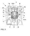
- a so-called clevis connection 20 is provided, which is formed by a fork end 20a arranged at the free end of the second lever arm 2b of the pedal lever 2 and a fork head receptacle 20b arranged on the lever arm end 9a of the second inner spring guide element 9 ( Fig. 1 to 3 ).
- first outer and second inner spring guide element 8, 9 mutually corresponding and an axial relative movement between the two spring guide elements 8, 9 limiting and a Montageverbund effecting positive locking means 21 in the form of latching hooks on the second inner spring guide element 9 and undercuts on the first guide means 13 of the first outer.
- the assembly of the Studentstot Vietnamesefederan extract 6 is preferably carried out such that initially the first outer spring guide member 8 equipped with the helical compression spring 17 and subsequently completed with the second inner spring guide element 9 by the tubular part of the second inner spring guide element 9 in the tubular first guide means 13 of the first outer spring guide element 5 is inserted axially until the said positive locking means 21 engage.
- the length of the helical compression spring 17 is preferably chosen such that it already experiences a certain bias.
- the above exemplary embodiment is based on a cup-shaped first outer and a tubular second inner spring guiding element 8, 9.
- the invention is not limited to this selected embodiment, but for the skilled person certainly comprehensible under the condition of forming an annular space 16 and ensuring a radial support and axial displacement of the second inner spring guide element 9 in the first outer spring guide element 8 also a first outer guide element 8, which tubular and a second inner guide member 9, which is pot-shaped or rod-shaped (not shown in detail).
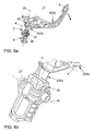
- the pedal lever 2 is in accordance with Fig. 7a, 7b at a time “t 1 " (initial position) for releasing the clutch operated respectively according to Fig. 7a Pressed down, the second inner spring guide element 9 is first pressed against the spring force of the helical compression spring 17 in the cup-shaped first outer spring guide element 8, while the first outer spring guide element 8 is supported on the bearing block 3.
- a formed by the clevis connection 20 bearing point 22 is initially in an initial position laterally outside of an imaginary connecting line 23 which in a common plane arranged on the axis of rotation 4 of the pedal lever 2 bearing point 24 with a arranged on the axis of rotation 25 of the first outer spring guide element 8 bearing point 26th combines.
Landscapes
- Engineering & Computer Science (AREA)
- Physics & Mathematics (AREA)
- General Physics & Mathematics (AREA)
- Automation & Control Theory (AREA)
- Transportation (AREA)
- Mechanical Engineering (AREA)
- Arrangement And Mounting Of Devices That Control Transmission Of Motive Force (AREA)
- Mechanical Control Devices (AREA)
Abstract
Description
Die Erfindung betrifft ein Fußhebelwerk für ein Fahrzeug, insbesondere Kraftfahrzeug, nach dem Oberbegriff des Patentanspruchs 1 der Erfindung.The invention relates to a pedal mechanism for a vehicle, in particular a motor vehicle, according to the preamble of
Aus der Praxis ist es seit geraumer Zeit bekannt, ein die Kupplungsbetätigung unterstützendes Federelement so anzuordnen, dass dieses zunächst der Kupplungspedalbetätigung entgegen wirkt und nach einem bestimmten Schwenkweg des Pedalhebels ein Moment auf denselben erzeugt, welches im gleichen Sinne wie die vom Fahrzeugführer aufgewendete Pedalkraft wirkt. Derartige Anordnungen wirken nach dem an sich bekannten Übertotpunktfeder-Prinzip, bei dem sich der Kraftvektor nach Überschreiten des Übertotpunktes (Kraftumkehrpunktes) umkehrt. Insoweit wird auch auf die einleitenden Ausführungen in der
So ist aus besagter
Aufgabe der Erfindung ist es, ein Fußhebelwerk für ein Fahrzeug, insbesondere Kraftfahrzeug, mit einer alternativen Übertotpunktfederanordnung zu schaffen, welche einfach und kostengünstig herstellbar sowie montierbar ist und bei geringem Bauraumbedarf eine sichere Funktion gewährleistet.The object of the invention is to provide a pedal system for a vehicle, in particular motor vehicle, with an alternative Übertotpunktfederanordnung which is simple and inexpensive to manufacture and assemble and ensures safe operation with low space requirement.
Ausgehend von einen Fußhebelwerk für ein Fahrzeug, insbesondere Kraftfahrzeug, mit einem in einem Lagerbock um eine Drehachse schwenkbeweglich gelagerten zweiarmigen Pedalhebel, wobei ein erster Hebelarm desselben an seinem freien Ende eine Pedalplatte trägt und ein zweiter Hebelarm mit einer Übertotpunktfederanordnung verbunden ist, wird die gestellte Aufgabe dadurch gelöst, dass die Übertotpunktfederanordnung ein erstes äußeres und ein zweites inneren Federführungselement aufweist, wobei das erste äußere Federführungselement mit einem zum zweiten Hebelarm des Pedalhebels zugewandten Ende und einem vom zweiten Hebelarm abgewandten Ende sowie mit einer Seitenwandung ausgebildet ist, wobei das zweite innere Federführungselement innerhalb des ersten äußeren Federführungselementes, einen Ringraum zwischen dem ersten äußeren und dem zweiten inneren Federführungselement ausbildend, in axialer Richtung des ersten äußeren Federführungselementes gleitgelagert ist, wobei innerhalb des besagten Ringraumes zumindest eine Schraubendruckfeder angeordnet ist, die sich ihrerseits einenends am ersten äußeren Federführungselement und anderenends am zweiten inneren Federführungselement abstützt, wobei das erste äußere Federführungselement mittels an seinem dem zweiten Hebelarm des Pedalhebels zugewandten Ende angeordneter Lagermittel am Lagerbock schwenkgelagert ist, und wobei am ebenfalls dem zweiten Hebelarm des Pedalhebels zugewandten Ende des zweiten inneren Federführungselementes der zweite Hebelarm angebunden ist.Starting from a pedal mechanism for a vehicle, especially a motor vehicle, with a two-armed pedal lever pivotally mounted in a bearing block about a rotation axis, wherein a first lever arm thereof carries a pedal plate at its free end and a second lever arm is connected to a Übertotpunktfederanordnung, the object is characterized in that the Übertotpunktfederanordnung comprises a first outer and a second inner spring guide element, wherein the first outer spring guide element is formed with an end facing away from the second lever arm of the pedal lever and an end facing away from the second lever arm and with a side wall, wherein the second inner spring guide element within the first outer spring guide element, an annular space between the first outer and the second inner spring guide element forming, is slidably mounted in the axial direction of the first outer spring guide element, wherein i at least one helical compression spring is arranged within said annular space, which in turn is supported at one end on the first outer spring guide element and the other on the second inner spring guide element, wherein the first outer spring guide element is pivotally mounted on the bearing block by means disposed at its end facing the second lever arm of the pedal lever bearing means, and wherein is also connected to the second lever arm of the pedal lever facing the end of the second inner spring guide element of the second lever arm.
Durch diese Maßnahme ist ein Fußhebelwerk mit einer kompakt ausgebildeten Übertotpunktfederanordnung geschaffen, deren Bau und Funktionsraum auf ein Minimum reduziert ist, da die erforderlichen Anbindungen desselben an den Pedalhebel und den Lagerbock unmittelbar benachbart zueinander angeordnet sind, nämlich an Enden der Federführungselemente, die dem Pedalhebel bzw. dessen zweiten Hebelarm zugewandt sind.By this measure, a pedal mechanism is provided with a compact Übertotpunktfederanordnung whose construction and functional space is reduced to a minimum, since the necessary connections thereof to the pedal lever and the Bearing block are arranged immediately adjacent to each other, namely at the ends of the spring guide elements, which face the pedal lever or its second lever arm.
Wie die Erfindung weiter vorsieht, können das erste äußere und das zweite innere Federführungselement zueinander korrespondierende Führungsmittel zur definierten axialen Führung des zweiten inneren Federführungselementes im ersten äußeren Federführungselement aufweisen, wodurch die Funktion der Übertotpunktfederanordnung beeinträchtigende Fehlstellungen insbesondere der beiden relativ zueinander teleskopierbaren Federführungselemente vorteilhaft vermeidbar sind.As the invention further provides, the first outer and the second inner spring guide member may mutually corresponding guide means for defined axial guidance of the second inner spring guide element in the first outer spring guide element, whereby the function of the Übertotpunktfederanordnung impairing malpositions of the two relatively telescoping spring guide elements are advantageously avoidable.
Dabei ist es für einen besonders kompakten Aufbau und eine einfach herzustellende Gleitlagerung der beiden Federführungselemente zueinander von Vorteil, wenn das erste äußere Federführungselement topf- oder rohrförmig und/oder das zweite innere Federführungselement topf-, rohr- oder stabförmig ausgebildet ist.It is advantageous for a particularly compact design and easy to produce sliding bearing of the two spring guide elements to each other when the first outer spring guide pot or tubular and / or the second inner spring guide cup, tubular or rod-shaped.
Besonders vorteilhaft können dabei die Führungsmittel derart ausgebildet sein, dass das topf-, rohr- oder stabförmig ausgebildete zweite innere Federführungselement beidenends im ersten äußeren Federführungselement gleitgelagert ist, woraus eine erhöhte Funktionssicherheit der Übertotpunktfederanordnung resultiert. Wie die Erfindung noch vorsieht, kann der Ringraum in Abhängigkeit vom Durchmesser der Schraubendruckfeder in seiner radialen Ausdehnung derart gewählt sein, dass eine gleitende Seitenabstützung der zumindest einen Schraubendruckfeder durch zumindest eines der Federführungselemente über den Federweg, vorzugsweise gesamten Federweg, gestattet ist. Eine derartige Seitenabstützung verhindert ein etwaiges für die Funktionsfähigkeit der Übertotpunktfederanordnung nachteiliges seitliches Ausknicken der Schraubendruckfeder. Des Weiteren kann vorgesehen sein, dass erstes äußeres und zweites inneres Federführungselement zueinander korrespondierende und eine axiale Relativbewegung zwischen den beiden Federführungselementen begrenzende sowie einen Montageverbund bewirkende Formschlussmittel aufweisen. Die Übertotpunktfederanordnung kann dadurch vorteilhaft als vormontiertes Bauteil mit unverlierbar zusammengehaltenen Einzelbestandteilen sowie mit vorgespannter Schraubendruckfeder für den Endmontageprozess eines Fahrzeugs bereitgestellt werden, wobei dann lediglich zwei Befestigungsmaßnahmen erforderlich werden. Ferner kann die Anbindung des zweiten Hebelarms an das zweite innere Federführungselement durch eine Gabelkopfanbindung bewirkt sein, welche durch einen Gabelkopf, der seinerseits formschlüssig mit einer Gabelkopfaufnahme verbindbar ist, gebildet ist. Weiter vorteilhaft können bauraumminimierend und statisch günstig sowohl der Pedalhebel als auch die Übertotpunktfederanordnung zwischen zwei Seitenwangen des Lagerbocks schwenkgelagert sein. Schließlich kann vorgesehen sein, dass die Bestandteile der Übertotpunktfederanordnung, ausgenommen die zumindest eine Schraubenfeder, aus Kunststoff bestehen, woraus Gewichts- und Kosteneinsparungen im Hinblick auf herkömmliche Übertotpunktfederanordnungen resultieren. Die Erfindung betrifft auch ein Fahrzeug, insbesondere Kraftfahrzeug, mit einem Fußhebelwerk der vorstehend beschriebenen Art.Particularly advantageously, the guide means can be designed such that the pot-, pipe- or rod-shaped second inner spring guide element is slidably mounted in both ends in the first outer spring guide element, resulting in an increased reliability of Übertotpunktfederanordnung results. As the invention still provides, the annular space may be selected depending on the diameter of the helical compression spring in its radial extent such that a sliding side support of the at least one helical compression spring by at least one of the spring guide elements on the spring travel, preferably total spring travel is permitted. Such side support prevents any adverse for the functioning of the Übertotpunktfederanordnung lateral buckling of the helical compression spring. Furthermore, it can be provided that first outer and second inner spring guide element have mutually corresponding and an axial relative movement between the two spring guide elements limiting and a mounting assembly causing interlocking means. The Übertotpunktfederanordnung can be advantageously provided as a preassembled component with captive held together individual components as well as with biased helical compression spring for the final assembly process of a vehicle, in which case only two attachment measures are required. Further, the connection of the second lever arm to the second inner spring guide element may be effected by a clevis connection, which is formed by a clevis, which in turn is positively connected to a clevis receptacle connected. Further advantageous space-minimizing and statically favorable both the pedal lever and the Übertotpunktfederanordnung between two side walls of the bearing block be pivoted. Finally, it can be provided that the components of the Übertotpunktfederanordnung, except the at least one coil spring, made of plastic, resulting in weight and cost savings in terms of conventional Übertotpunktfederanordnungen. The invention also relates to a vehicle, in particular a motor vehicle, with a pedal mechanism of the type described above.
Die Erfindung wird nachstehend anhand eines in den Zeichnungen schematisch dargestellten Ausführungsbeispieles erläutert. Es zeigen:
- Fig. 1
- das erfindungsgemäße Fußhebelwerk in einer perspektivischen Ansicht,
- Fig. 2
- das Fußhebelwerk nach
Fig. 1 in einer Seitenansicht mit der Darstellung des Kupplungspedals und einer erfindungswesentlichen Übertotpunktfederanordnung des Fußhebelwerks in zwei Betriebsstellungen, - Fig. 3
- die Ansicht "A" nach
Fig. 1 , - Fig. 4
- eine perspektivische Ansicht der erfindungswesentlichen Übertotpunktfederanordnung des Fußhebelwerks nach
Fig. 1 , - Fig. 5
- den Schnitt "I-I" nach
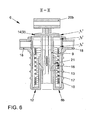
Fig. 4 , - Fig. 6
- den Schnitt "II-II" nach
Fig. 4 , - Fig. 7a
- das erfindungsgemäße Fußhebelwerk nach
Fig. 1 in seiner Funktion zu Beginn einer Kupplungsbetätigung zum Öffnen der Kupplung zu einem Zeitpunkt "t1" (Ausgangsstellung), - Fig. 7b
- die Ansicht "B" nach
Fig. 7a , - Fig. 8a
- das erfindungsgemäße Fußhebelwerk nach
Fig. 1 in seiner Funktion während der Kupplungsbetätigung zum Öffnen der Kupplung zu einem Zeitpunkt "t2" (Erreichen des Kraftumkehrpunktes der Übertotpunktfederanordnung), - Fig. 8b
- die Ansicht "C" nach
Fig. 8a , - Fig. 9a
- das erfindungsgemäße Fußhebelwerk nach
Fig. 1 in seiner Funktion während der Kupplungsbetätigung zum Öffnen der Kupplung zu einem Zeitpunkt "t3" (Endstellung), und - Fig. 9b
- die Ansicht "D" nach
Fig. 9a .
- Fig. 1
- the pedal system according to the invention in a perspective view,
- Fig. 2
- the pedal mechanism after
Fig. 1 in a side view with the representation of the clutch pedal and a erfindung essential Overtotpunktfederanordnung the pedal mechanism in two operating positions, - Fig. 3
- the view "A" after
Fig. 1 . - Fig. 4
- a perspective view of the inventive over-center spring arrangement of the pedal system after
Fig. 1 . - Fig. 5
- the section "II" after
Fig. 4 . - Fig. 6
- the section "II-II" after
Fig. 4 . - Fig. 7a
- after the pedal system according to the invention
Fig. 1 in its function at the beginning of a clutch operation to open the clutch at a time "t 1 " (initial position), - Fig. 7b
- the view "B" after
Fig. 7a . - Fig. 8a
- after the pedal system according to the invention
Fig. 1 in its function during the clutch operation to open the clutch at a time "t 2 " (reaching the Kraftumkehrpunktes the Übertotpunktfederanordnung), - Fig. 8b
- the view "C" after
Fig. 8a . - Fig. 9a
- after the pedal system according to the invention
Fig. 1 in its function during the clutch operation to open the clutch at a time "t 3 " (end position), and - Fig. 9b
- the view "D" after
Fig. 9a ,
Die
Die Fußkraft des Fahrzeugführers wird dabei über den in einem Lagerbock 3 um eine Drehachse 4 schwenkbeweglich gelagerten Pedalhebel 2 und ein nicht näher dargestelltes Gestänge auf den Kolben des besagten Geberzylinders übertragen. Der im Druckraum des Geberzylinders erzeugte Fluiddruck pflanzt sich in zugeordneten Fluidleitungen bis zum Nehmerzylinder fort und bewirkt am Kolben des Nehmerzylinders eine Kraft, die über ein oder mehrere Betätigungsglieder, wie beispielsweise einem Stößel mit angeschlossenem Ausrückhebel den Ausrücker betätigt und die Kupplung auskuppelt respektive öffnet. Zum Einkuppeln respektive zum Schließen der Kupplung drückt üblicherweise eine Membranfeder der Kupplung über den Ausrücker, den Ausrückhebel sowie den Stößel die Kolben von Nehmerzylinder und Geberzylinder samt dem Pedalhebel 2 in die Ausgangsstellung zurück.The foot force of the vehicle driver is transmitted to the piston of said master cylinder via the
Der Pedalhebel 2 trägt am freien Ende eines ersten Hebelarmes 2a eine Pedalplatte 5 und verfügt über einen zum ersten Hebelarm 2a weitestgehend rechtwinklig abgestellten zweiten Hebelarm 2b, dessen freies Ende mit einer Übertotpunktfederanordnung 6 verbunden ist. Ferner ist eine an sich bekannte Rückstellfeder 7, vorliegend in Form einer Schraubenzugfeder vorgesehen, welche einenends am Lagerbock 3 und anderenends am Pedalhebel 2 befestigt ist und nach Betätigung des Pedalhebels 2 die Rückstellung desselben in seine Ausgangsstellung unterstützt.The
Sowohl der Pedalhebel 2 als auch die Übertotpunktfederanordnung 6 sind platzsparend und statisch günstig zwischen zwei Seitenwangen 3a, 3b des Lagerbocks 3 schwenkgelagert.Both the
Die Übertotpunktfederanordnung 6 weist ihrerseits ein erstes äußeres Federführungselement 8 und ein in demselben gleitgelagertes respektive teleskopierbares zweites inneres. Federführungselement 9 auf (vgl. insbes.
Insoweit ist vorliegend das erste äußere Federführungselement 8 überwiegend topfförmig mit einem dem zweiten Hebelarm 2b des Pedalhebels 2 zugewandten Ende 8a und einem vom zweiten Hebelarm 2b abgewandten Ende 8b, sowie mit einer abschnittsweise geschlossenen Seitenwandung 10 ausgebildet. Die Topföffnung 11 befindet sich hebelarmseitig, wogegen der Topfboden 12 das vom zweiten Hebelarm 2b abgewandte Ende 8b bildet.In that regard, in the present case, the first outer
Das zweite innere Federführungselement 9 ist seinerseits überwiegend rohrförmig ausgebildet und mit seinem vom zweiten Hebelarm 2b abgewandten Ende 9b innerhalb eines sich vom Topfboden 12 zur Topföffnung 11 hin sich axial erstreckenden ersten Führungsmittels 13 in Form einer rohrförmigen Aufnahme axial geführt. Am dem zweiten Hebelarm 2b zugewandten Ende 9a des zweiten inneren Federführungselementes 9 ist ein Stirnflansch 14 vorgesehen, der seinerseits sich radial an der Innenkontur der Seitenwandung 10 abstützt und in nutenförmigen zweiten Führungsmitteln 15 axial geführt ist.The second inner
Zwischen dem ersten äußeren Federführungselement 8 und dem zweiten inneren Federführungselement 9 ist ein Ringraum 16 gebildet, in welchem eine Schraubendruckfeder 17 angeordnet ist. Die Schraubendruckfeder 17 stützt sich einenends am ersten äußeren Federführungselement 8, vorliegend am Topfboden 12 desselben, und anderenends am besagten Stirnflansch 14 des zweiten inneren Federführungselementes 9 ab.Between the first outer
Der gebildete Ringraum 16 ist dabei in Abhängigkeit vom Durchmesser der Schraubendruckfeder 17 in seiner radialen Ausdehnung derart gewählt respektive bemessen, dass eine gleitende Seitenabstützung der Schraubendruckfeder 17 durch wenigstens eines der Federführungselemente 8, 9 über den Federweg, vorzugsweise über den gesamten Federweg, gestattet ist.The formed
Das erste äußere Federführungselement 8 verfügt an seinem dem zweiten Hebelarm 2b des Pedalhebels 2 zugewandten Ende 8a über zwei radial gegenüberliegend angeordnete und von der Seitenwandung 10 des ersten äußeren Federführungselementes 8 radial abgestellte Lagermittel 18 in Form von Drehzapfen, die ihrerseits in dazu korrespondierenden Aufnahmen 19 der Seitenwangen 3a, 3b des Lagerbocks 3 schwenkgelagert sind.The first outer
Am ebenfalls dem zweiten Hebelarm 2b des Pedalhebels 2 zugewandten Ende 9a des zweiten inneren Federführungselementes 9 ist das freie Ende des zweiten Hebelarms 2b des Pedalhebels 2 angelenkt. Hierzu ist eine sogenannte Gabelkopfanbindung 20 vorgesehen, welche durch einen am freien Ende des zweiten Hebelarms 2b des Pedalhebels 2 angeordneten Gabelkopf 20a und eine am hebelarmseitigen Ende 9a des zweiten inneren Federführungselementes 9 angeordnete Gabelkopfaufnahme 20b gebildet ist (
Wie insbesondere aus
Die Montage der Übertotpunktfederanordnung 6 erfolgt dabei vorzugsweise derart, dass zunächst das erste äußere Federführungselement 8 mit der Schraubendruckfeder 17 bestückt und nachfolgend mit dem zweiten inneren Federführungselement 9 komplettiert wird, indem der rohrförmige Teil des zweiten inneren Federführungselementes 9 in das rohrförmig ausgebildete erste Führungsmittel 13 des ersten äußeren Federführungselementes 5 axial eingeführt wird, bis die besagten Formschlussmittel 21 verrasten. Die Länge der Schraubendruckfeder 17 ist dabei vorzugsweise derart gewählt, dass sie bereits eine bestimmte Vorspannung erfährt.The assembly of the
Der Vollständigkeit halber sei darauf hingewiesen, dass vorliegend die Bestandteile der Übertotpunktfederanordnung 6, ausgenommen deren Schraubendruckfeder 17, aus einem Kunststoff nach beispielsweise einem an sich bekannten Spritzgießverfahren hergestellt sind.For the sake of completeness it should be noted that in the present case the components of the
Vorstehendes Ausführungsbeispiel stellt auf ein topfförmig ausgebildetes erstes äußeres und ein rohrförmig ausgebildetes zweites inneres Federführungselement 8, 9 ab. Die Erfindung beschränkt sich jedoch nicht auf diese gewählte Ausgestaltung, sondern erfasst für den Fachmann sicherlich leicht nachvollziehbar unter der Voraussetzung der Bildung eines Ringraumes 16 sowie der Gewährleistung einer radialen Abstützung und einer axialen Verschiebbarkeit des zweiten inneren Federführungselementes 9 im ersten äußeren Federführungselement 8 auch ein erstes äußeres Führungselement 8, welches rohrförmig und ein zweites inneres Führungselement 9, welches topf- oder stabförmig ausgebildet ist (nicht näher dargestellt).The above exemplary embodiment is based on a cup-shaped first outer and a tubular second inner
Nachfolgend wird unter Verweis auf insbesondere die
Gesetzt den Fall, der Pedalhebel 2 wird gemäß den
Ein durch die Gabelkopfanbindung 20 gebildeter Lagerpunkt 22 liegt zunächst in einer Ausgangsstellung seitlich außerhalb einer imaginären Verbindungslinie 23, welche in einer gemeinsamen Ebene einen auf der Drehachse 4 des Pedalhebels 2 angeordneten Lagerpunkt 24 mit einem auf der Drehachse 25 des ersten äußeren Federführungselementes 8 angeordneten Lagerpunkt 26 verbindet.A formed by the
Während der Bewegung des Pedalhebels 2 und des weiteren Zusammendrückens der Schraubendruckfeder 17 nähern sich die Verbindungslinie 23 und der durch die Gabelkopfanbindung 20 gebildete Lagerpunkt 22 an, bis der Lagerpunkt 22 in einer Flucht mit den Lagerpunkten 24 und 26 liegt respektive auf der Verbindungslinie 23 zum Liegen kommt.During the movement of the
Zu diesem Zeitpunkt "t2" (vgl.
Die Schraubendruckfeder 17 entspannt sich und das zweite innere Federführungselement 9 bewegt sich wieder zurück bis der Pedalhebel 2 zu einem Zeitpunkt "t3" seine untere Endstellung erreicht hat. Zu diesem Zeitpunkt "t3" hat der Lagerpunkt 22 besagte imaginäre Verbindungslinie 23 wider verlassen und eine zur Ausgangstellung gegenüberliegend angeordnete Endstellung erreicht (vgl.
Während der gesamten Bewegung vollführt die Übertotpunktfederanordnung 6 eine Schwenkbewegung um die Drehachse 25 des ersten äußeren Federführungselementes 8 (vgl. insbes.
Wird der Pedalhebel 2 in seine Ausgangstellung zurück überführt, kehrt sich der vorbeschriebene Bewegungsablauf um.If the
Im Wesentliche ist demgemäß herauszustellen, dass beim Betätigen des Pedalhebels 2 durch den Fahrzeugführer bis zum Erreichen der Übertotpunktstellung der Übertotpunktfederanordnung 6 zunächst eine Kraft gegen die Schraubendruckfeder 17 aufgebracht werden muss und nach Überschreiten besagter Übertotpunktstellung die Schraubendruckfeder 17 die weitere Betätigung des Pedalhebels 2 unterstützt. Durch diese von der besonders ausgebildeten Übertotpunktfederanordnung 6 bewirkte Kinematik kann definiert eine bestimmte Kupplungskennlinie erzeugt werden.Essentially, it should be emphasized that when pressing the
- 11
- FußhebelwerkFoot Lever
- 22
- Pedalhebelpedal lever
- 2a2a
- erster Hebelarmfirst lever arm
- 2b2 B
- zweiter Hebelarmsecond lever arm
- 33
- Lagerbockbearing block
- 3a3a
- Seitenwangeside cheek
- 3b3b
- Seitenwangeside cheek
- 44
- Drehachse (Pedalhebel 2)Rotary axis (pedal lever 2)
- 55
- Pedalplattepedal plate
- 66
- ÜbertotpunktfederanordnungÜbertotpunktfederanordnung
- 77
- RückstellfederReturn spring
- 88th
- erstes äußeres Federführungselementfirst outer spring guide element
- 8a8a
-
dem Pedalhebel 2 zugewandtes Endethe
pedal lever 2 facing the end - 8b8b
-
vom Pedalhebel 2 abgewandtes Endefrom the
pedal lever 2 opposite end - 99
- zweites inneres Federführungselementsecond inner spring guide element
- 9a9a
-
dem Pedalhebel 2 zugewandtes Endethe
pedal lever 2 facing the end - 9b9b
-
vom Pedalhebel 2 abgewandtes Endefrom the
pedal lever 2 opposite end - 1010
- Seitenwandungsidewall
- 1111
- Topföffnungcup opening
- 1212
- Topfbodenpot base
- 1313
- erstes Führungsmittelfirst guide
- 1414
- Stirnflanschend flange
- 1515
- zweites Führungsmittelsecond guide means
- 1616
- Ringraumannulus
- 1717
- SchraubendruckfederHelical compression spring
- 1818
- Lagermittelbearing means
- 1919
- Aufnahmeadmission
- 2020
- GabelkopfanbindungClevis connection
- 20a20a
- Gabelkopfclevis
- 20b20b
- GabelkopfaufnahmeClevis recording
- 2121
- FormschlussmittelFit means
- 2222
- Lagerpunkt (Gabelkopfanbindung 20)Bearing point (clevis connection 20)
- 2323
- Verbindungslinieconnecting line
- 2424
- Lagerpunkt (Pedalhebel 2)Bearing point (pedal lever 2)
- 2525
- Drehachse (erstes äußeres Federführungselement 8)Rotary axis (first outer spring guide element 8)
- 2626
- Lagerpunkt (erstes äußeres Federführungselement 8)Bearing point (first outer spring guide element 8)
Claims (10)
Applications Claiming Priority (1)
| Application Number | Priority Date | Filing Date | Title |
|---|---|---|---|
| DE102010044417.0A DE102010044417B4 (en) | 2010-09-04 | 2010-09-04 | Pedal mechanism for a vehicle |
Publications (1)
| Publication Number | Publication Date |
|---|---|
| EP2426018A1 true EP2426018A1 (en) | 2012-03-07 |
Family
ID=44644876
Family Applications (1)
| Application Number | Title | Priority Date | Filing Date |
|---|---|---|---|
| EP11006641A Withdrawn EP2426018A1 (en) | 2010-09-04 | 2011-08-12 | Foot pedal assembly for a vehicle |
Country Status (2)
| Country | Link |
|---|---|
| EP (1) | EP2426018A1 (en) |
| DE (1) | DE102010044417B4 (en) |
Cited By (4)
| Publication number | Priority date | Publication date | Assignee | Title |
|---|---|---|---|---|
| CN105365795A (en) * | 2014-08-07 | 2016-03-02 | 株式会社F.泰克 | Vehicle pedal arm |
| CN107585024A (en) * | 2016-07-06 | 2018-01-16 | Zf腓特烈斯哈芬股份公司 | Pedal force simulated assembly and motor vehicle |
| CN107589778A (en) * | 2016-07-06 | 2018-01-16 | Zf腓特烈斯哈芬股份公司 | Pedal force simulated assembly and motor vehicle |
| CN108638856A (en) * | 2017-03-15 | 2018-10-12 | Zf腓特烈斯哈芬股份公司 | Pedal effort simulated assembly and motor vehicle |
Families Citing this family (3)
| Publication number | Priority date | Publication date | Assignee | Title |
|---|---|---|---|---|
| DE102012010084B4 (en) * | 2012-05-23 | 2019-11-28 | Volkswagen Aktiengesellschaft | Over-center spring arrangement |
| DE102014217199B3 (en) | 2014-08-28 | 2016-01-14 | Ford Global Technologies, Llc | Clutch pedal system and master cylinder for a clutch pedal system of a vehicle |
| DE102016212354A1 (en) * | 2016-07-06 | 2018-01-11 | Zf Friedrichshafen Ag | Pedal force simulation arrangement and motor vehicle |
Citations (8)
| Publication number | Priority date | Publication date | Assignee | Title |
|---|---|---|---|---|
| DE1235153B (en) * | 1965-06-24 | 1967-02-23 | Daimler Benz Ag | Device to support the pedal force, preferably for the actuation of a disengageable vehicle clutch, especially a main clutch for motor vehicles |
| DE2262878A1 (en) * | 1972-12-22 | 1974-07-11 | Porsche Ag | DEVICE FOR SUPPORTING THE PEDAL FORCE IN MOTOR VEHICLE CLUTCHES |
| FR2458433A1 (en) * | 1979-06-07 | 1981-01-02 | Volkswagenwerk Ag | Spring mounting for clutch pedal - has off axis mounting with parallel servo drive |
| EP0169138A2 (en) * | 1984-07-20 | 1986-01-22 | Automobiles Peugeot | Spring-assisted clutch control for a motor vehicle |
| DE20220483U1 (en) | 2002-05-15 | 2003-10-23 | Innotec Forschungs & Entw Gmbh | Coupling member for motor vehicle pedal system, modifies pedal-force characteristic set by spring characteristic of top-dead-center spring |
| EP1596268A2 (en) | 2004-05-14 | 2005-11-16 | Audi Ag | Bearing device for a spring arrangement |
| DE102005035067A1 (en) * | 2004-08-14 | 2006-02-23 | Luk Lamellen Und Kupplungsbau Beteiligungs Kg | Arrangement for operating of clutch in drive train of motor vehicle has spring connected by first fastening point to means which describe curved path depending upon position of clutch pedal, and by second fastening point to clutch pedal |
| DE102004045530A1 (en) * | 2004-09-20 | 2006-03-23 | Bayerische Motoren Werke Ag | Clutch hand lever of motorcycle, comprising spring accommodated in swivel mounted cup supported against bottom |
Family Cites Families (1)
| Publication number | Priority date | Publication date | Assignee | Title |
|---|---|---|---|---|
| DE10011760A1 (en) | 2000-03-10 | 2001-09-13 | Audi Ag | Device for actuating operating device in vehicle has linkage joined to pedal and connected to pivotable element at other end, whereby spring engages linkage between joint positions |
-
2010
- 2010-09-04 DE DE102010044417.0A patent/DE102010044417B4/en active Active
-
2011
- 2011-08-12 EP EP11006641A patent/EP2426018A1/en not_active Withdrawn
Patent Citations (8)
| Publication number | Priority date | Publication date | Assignee | Title |
|---|---|---|---|---|
| DE1235153B (en) * | 1965-06-24 | 1967-02-23 | Daimler Benz Ag | Device to support the pedal force, preferably for the actuation of a disengageable vehicle clutch, especially a main clutch for motor vehicles |
| DE2262878A1 (en) * | 1972-12-22 | 1974-07-11 | Porsche Ag | DEVICE FOR SUPPORTING THE PEDAL FORCE IN MOTOR VEHICLE CLUTCHES |
| FR2458433A1 (en) * | 1979-06-07 | 1981-01-02 | Volkswagenwerk Ag | Spring mounting for clutch pedal - has off axis mounting with parallel servo drive |
| EP0169138A2 (en) * | 1984-07-20 | 1986-01-22 | Automobiles Peugeot | Spring-assisted clutch control for a motor vehicle |
| DE20220483U1 (en) | 2002-05-15 | 2003-10-23 | Innotec Forschungs & Entw Gmbh | Coupling member for motor vehicle pedal system, modifies pedal-force characteristic set by spring characteristic of top-dead-center spring |
| EP1596268A2 (en) | 2004-05-14 | 2005-11-16 | Audi Ag | Bearing device for a spring arrangement |
| DE102005035067A1 (en) * | 2004-08-14 | 2006-02-23 | Luk Lamellen Und Kupplungsbau Beteiligungs Kg | Arrangement for operating of clutch in drive train of motor vehicle has spring connected by first fastening point to means which describe curved path depending upon position of clutch pedal, and by second fastening point to clutch pedal |
| DE102004045530A1 (en) * | 2004-09-20 | 2006-03-23 | Bayerische Motoren Werke Ag | Clutch hand lever of motorcycle, comprising spring accommodated in swivel mounted cup supported against bottom |
Cited By (5)
| Publication number | Priority date | Publication date | Assignee | Title |
|---|---|---|---|---|
| CN105365795A (en) * | 2014-08-07 | 2016-03-02 | 株式会社F.泰克 | Vehicle pedal arm |
| CN105365795B (en) * | 2014-08-07 | 2018-12-07 | 株式会社 F.泰克 | Pedal for vehicle arm |
| CN107585024A (en) * | 2016-07-06 | 2018-01-16 | Zf腓特烈斯哈芬股份公司 | Pedal force simulated assembly and motor vehicle |
| CN107589778A (en) * | 2016-07-06 | 2018-01-16 | Zf腓特烈斯哈芬股份公司 | Pedal force simulated assembly and motor vehicle |
| CN108638856A (en) * | 2017-03-15 | 2018-10-12 | Zf腓特烈斯哈芬股份公司 | Pedal effort simulated assembly and motor vehicle |
Also Published As
| Publication number | Publication date |
|---|---|
| DE102010044417B4 (en) | 2022-08-04 |
| DE102010044417A1 (en) | 2012-03-08 |
Similar Documents
| Publication | Publication Date | Title |
|---|---|---|
| EP2426018A1 (en) | Foot pedal assembly for a vehicle | |
| AT502487B1 (en) | DAMPER ARRANGEMENT | |
| DE102015008709A1 (en) | Parking lock module | |
| DE10121317B4 (en) | pedal device | |
| EP1070867B1 (en) | Device for actuating a clutch, especially for vehicles | |
| EP1659017B1 (en) | Apparatus for reduction of the pedal force | |
| DE2923027A1 (en) | DEVICE FOR ACTUATING A DISC SPRING CLUTCH OF A MOTOR VEHICLE, IN PARTICULAR A TRUCK | |
| EP1521004B1 (en) | Actuation device for a automobile clutch | |
| EP2492427B1 (en) | Fitting device for a movable furniture part | |
| EP1703160B1 (en) | Release mechanism for a friction clutch of a motor vehicle | |
| DE102005050760A1 (en) | Pedal force reduction device for motor vehicle, has piston rod indirectly connected to pedal in form-fitting manner | |
| EP0518159B1 (en) | Regulating device for a component, destined for a vehicle | |
| EP2079605B1 (en) | Actuating device for a fixing rod to be displaced in the longitudinal direction | |
| DE102005010211A1 (en) | Parking lock mechanism for use in motor vehicle, has casing radially arranged between connection rod and blocking device that is arranged on outer diameter of casing and is not spring-mounted and not pre-stressed and freely rotated | |
| DE102004024089B3 (en) | Bearing device for a spring arrangement | |
| DE102013216483A1 (en) | foot pedal | |
| EP2467278B1 (en) | Clutch pedal arrangement | |
| DE112020005798T5 (en) | Device for automatically adjusting the free play of a parking brake | |
| DE102016112187A1 (en) | Hinge of a front hood of a motor vehicle | |
| EP1618312B1 (en) | Bilateral drive | |
| DE19624605C1 (en) | Actuator for coupling in motor vehicle | |
| DE102010020332B4 (en) | Releaser with a slave cylinder and torque support | |
| WO2003042510A1 (en) | Drag lever of a valve mechanism in an internal combustion engine | |
| DE102008043247B3 (en) | Hypocycloidal release device for motor vehicle clutch, has contours formed along lines with radii with center point, respectively, where one radius is equal to twice of another radius and lines are arranged within pivot plane of lever | |
| DE102019132597A1 (en) | Switchable rocker arm or rocker arm |
Legal Events
| Date | Code | Title | Description |
|---|---|---|---|
| AK | Designated contracting states |
Kind code of ref document: A1 Designated state(s): AL AT BE BG CH CY CZ DE DK EE ES FI FR GB GR HR HU IE IS IT LI LT LU LV MC MK MT NL NO PL PT RO RS SE SI SK SM TR |
|
| AX | Request for extension of the european patent |
Extension state: BA ME |
|
| PUAI | Public reference made under article 153(3) epc to a published international application that has entered the european phase |
Free format text: ORIGINAL CODE: 0009012 |
|
| RAP1 | Party data changed (applicant data changed or rights of an application transferred) |
Owner name: VOLKSWAGEN AKTIENGESELLSCHAFT |
|
| STAA | Information on the status of an ep patent application or granted ep patent |
Free format text: STATUS: THE APPLICATION IS DEEMED TO BE WITHDRAWN |
|
| 18D | Application deemed to be withdrawn |
Effective date: 20120908 |