EP2425672B1 - Control of communciation devices for carrier aggregation - Google Patents
Control of communciation devices for carrier aggregation Download PDFInfo
- Publication number
- EP2425672B1 EP2425672B1 EP10726327.9A EP10726327A EP2425672B1 EP 2425672 B1 EP2425672 B1 EP 2425672B1 EP 10726327 A EP10726327 A EP 10726327A EP 2425672 B1 EP2425672 B1 EP 2425672B1
- Authority
- EP
- European Patent Office
- Prior art keywords
- component carriers
- transceiver
- control
- base station
- operable
- Prior art date
- Legal status (The legal status is an assumption and is not a legal conclusion. Google has not performed a legal analysis and makes no representation as to the accuracy of the status listed.)
- Active
Links
- 230000002776 aggregation Effects 0.000 title description 15
- 238000004220 aggregation Methods 0.000 title description 15
- 239000000969 carrier Substances 0.000 claims description 139
- 238000000034 method Methods 0.000 claims description 13
- 238000012544 monitoring process Methods 0.000 claims description 8
- 238000004590 computer program Methods 0.000 claims description 2
- 238000004891 communication Methods 0.000 description 35
- 230000011664 signaling Effects 0.000 description 30
- 230000005540 biological transmission Effects 0.000 description 10
- 230000000694 effects Effects 0.000 description 6
- 230000007246 mechanism Effects 0.000 description 6
- 230000004048 modification Effects 0.000 description 6
- 238000012986 modification Methods 0.000 description 6
- 238000013468 resource allocation Methods 0.000 description 6
- 230000008901 benefit Effects 0.000 description 4
- 230000008859 change Effects 0.000 description 4
- 238000010586 diagram Methods 0.000 description 4
- 101150014328 RAN2 gene Proteins 0.000 description 3
- 238000001228 spectrum Methods 0.000 description 3
- 101150069124 RAN1 gene Proteins 0.000 description 2
- 238000013459 approach Methods 0.000 description 2
- 230000009467 reduction Effects 0.000 description 2
- 101100087393 Caenorhabditis elegans ran-2 gene Proteins 0.000 description 1
- 108700026140 MAC combination Proteins 0.000 description 1
- 230000001413 cellular effect Effects 0.000 description 1
- 125000004122 cyclic group Chemical group 0.000 description 1
- 230000006870 function Effects 0.000 description 1
- 238000007726 management method Methods 0.000 description 1
- 238000005259 measurement Methods 0.000 description 1
- 230000004044 response Effects 0.000 description 1
- 239000002699 waste material Substances 0.000 description 1
Images


Classifications
-
- H—ELECTRICITY
- H04—ELECTRIC COMMUNICATION TECHNIQUE
- H04W—WIRELESS COMMUNICATION NETWORKS
- H04W72/00—Local resource management
- H04W72/12—Wireless traffic scheduling
- H04W72/121—Wireless traffic scheduling for groups of terminals or users
-
- H—ELECTRICITY
- H04—ELECTRIC COMMUNICATION TECHNIQUE
- H04L—TRANSMISSION OF DIGITAL INFORMATION, e.g. TELEGRAPHIC COMMUNICATION
- H04L5/00—Arrangements affording multiple use of the transmission path
- H04L5/0091—Signaling for the administration of the divided path
- H04L5/0096—Indication of changes in allocation
- H04L5/0098—Signalling of the activation or deactivation of component carriers, subcarriers or frequency bands
-
- H—ELECTRICITY
- H04—ELECTRIC COMMUNICATION TECHNIQUE
- H04W—WIRELESS COMMUNICATION NETWORKS
- H04W74/00—Wireless channel access
- H04W74/04—Scheduled access
-
- H—ELECTRICITY
- H04—ELECTRIC COMMUNICATION TECHNIQUE
- H04L—TRANSMISSION OF DIGITAL INFORMATION, e.g. TELEGRAPHIC COMMUNICATION
- H04L5/00—Arrangements affording multiple use of the transmission path
- H04L5/0001—Arrangements for dividing the transmission path
- H04L5/0003—Two-dimensional division
- H04L5/0005—Time-frequency
- H04L5/0007—Time-frequency the frequencies being orthogonal, e.g. OFDM(A), DMT
- H04L5/001—Time-frequency the frequencies being orthogonal, e.g. OFDM(A), DMT the frequencies being arranged in component carriers
-
- H—ELECTRICITY
- H04—ELECTRIC COMMUNICATION TECHNIQUE
- H04L—TRANSMISSION OF DIGITAL INFORMATION, e.g. TELEGRAPHIC COMMUNICATION
- H04L5/00—Arrangements affording multiple use of the transmission path
- H04L5/003—Arrangements for allocating sub-channels of the transmission path
- H04L5/0053—Allocation of signaling, i.e. of overhead other than pilot signals
-
- H—ELECTRICITY
- H04—ELECTRIC COMMUNICATION TECHNIQUE
- H04L—TRANSMISSION OF DIGITAL INFORMATION, e.g. TELEGRAPHIC COMMUNICATION
- H04L5/00—Arrangements affording multiple use of the transmission path
- H04L5/003—Arrangements for allocating sub-channels of the transmission path
- H04L5/0078—Timing of allocation
- H04L5/0087—Timing of allocation when data requirements change
-
- H—ELECTRICITY
- H04—ELECTRIC COMMUNICATION TECHNIQUE
- H04W—WIRELESS COMMUNICATION NETWORKS
- H04W36/00—Hand-off or reselection arrangements
- H04W36/06—Reselecting a communication resource in the serving access point
-
- H—ELECTRICITY
- H04—ELECTRIC COMMUNICATION TECHNIQUE
- H04W—WIRELESS COMMUNICATION NETWORKS
- H04W48/00—Access restriction; Network selection; Access point selection
- H04W48/08—Access restriction or access information delivery, e.g. discovery data delivery
- H04W48/12—Access restriction or access information delivery, e.g. discovery data delivery using downlink control channel
-
- H—ELECTRICITY
- H04—ELECTRIC COMMUNICATION TECHNIQUE
- H04W—WIRELESS COMMUNICATION NETWORKS
- H04W68/00—User notification, e.g. alerting and paging, for incoming communication, change of service or the like
-
- H—ELECTRICITY
- H04—ELECTRIC COMMUNICATION TECHNIQUE
- H04W—WIRELESS COMMUNICATION NETWORKS
- H04W72/00—Local resource management
- H04W72/04—Wireless resource allocation
- H04W72/044—Wireless resource allocation based on the type of the allocated resource
- H04W72/0453—Resources in frequency domain, e.g. a carrier in FDMA
-
- H—ELECTRICITY
- H04—ELECTRIC COMMUNICATION TECHNIQUE
- H04W—WIRELESS COMMUNICATION NETWORKS
- H04W72/00—Local resource management
- H04W72/20—Control channels or signalling for resource management
- H04W72/23—Control channels or signalling for resource management in the downlink direction of a wireless link, i.e. towards a terminal
-
- H—ELECTRICITY
- H04—ELECTRIC COMMUNICATION TECHNIQUE
- H04W—WIRELESS COMMUNICATION NETWORKS
- H04W72/00—Local resource management
- H04W72/30—Resource management for broadcast services
-
- H—ELECTRICITY
- H04—ELECTRIC COMMUNICATION TECHNIQUE
- H04W—WIRELESS COMMUNICATION NETWORKS
- H04W72/00—Local resource management
- H04W72/50—Allocation or scheduling criteria for wireless resources
- H04W72/53—Allocation or scheduling criteria for wireless resources based on regulatory allocation policies
-
- H—ELECTRICITY
- H04—ELECTRIC COMMUNICATION TECHNIQUE
- H04W—WIRELESS COMMUNICATION NETWORKS
- H04W76/00—Connection management
- H04W76/20—Manipulation of established connections
- H04W76/28—Discontinuous transmission [DTX]; Discontinuous reception [DRX]
-
- H—ELECTRICITY
- H04—ELECTRIC COMMUNICATION TECHNIQUE
- H04L—TRANSMISSION OF DIGITAL INFORMATION, e.g. TELEGRAPHIC COMMUNICATION
- H04L5/00—Arrangements affording multiple use of the transmission path
- H04L5/0001—Arrangements for dividing the transmission path
- H04L5/0014—Three-dimensional division
- H04L5/0023—Time-frequency-space
-
- H—ELECTRICITY
- H04—ELECTRIC COMMUNICATION TECHNIQUE
- H04W—WIRELESS COMMUNICATION NETWORKS
- H04W88/00—Devices specially adapted for wireless communication networks, e.g. terminals, base stations or access point devices
- H04W88/02—Terminal devices
-
- H—ELECTRICITY
- H04—ELECTRIC COMMUNICATION TECHNIQUE
- H04W—WIRELESS COMMUNICATION NETWORKS
- H04W88/00—Devices specially adapted for wireless communication networks, e.g. terminals, base stations or access point devices
- H04W88/08—Access point devices
-
- Y—GENERAL TAGGING OF NEW TECHNOLOGICAL DEVELOPMENTS; GENERAL TAGGING OF CROSS-SECTIONAL TECHNOLOGIES SPANNING OVER SEVERAL SECTIONS OF THE IPC; TECHNICAL SUBJECTS COVERED BY FORMER USPC CROSS-REFERENCE ART COLLECTIONS [XRACs] AND DIGESTS
- Y02—TECHNOLOGIES OR APPLICATIONS FOR MITIGATION OR ADAPTATION AGAINST CLIMATE CHANGE
- Y02D—CLIMATE CHANGE MITIGATION TECHNOLOGIES IN INFORMATION AND COMMUNICATION TECHNOLOGIES [ICT], I.E. INFORMATION AND COMMUNICATION TECHNOLOGIES AIMING AT THE REDUCTION OF THEIR OWN ENERGY USE
- Y02D30/00—Reducing energy consumption in communication networks
- Y02D30/70—Reducing energy consumption in communication networks in wireless communication networks
Definitions
- the present invention relates to communications devices, particularly but not exclusively devices operating according to the 3GPP standards or equivalents or derivatives thereof.
- the invention has particular but not exclusive relevance to the impacts of carrier aggregation that is to be used in LTE-Advanced as currently defined in 3GPP standards documentation TR 36.814.
- LTE Rel 8 a transmission band of 20MHz was defined.
- LTE-Advanced carrier aggregation will be used to support system bandwidths up to 100 MHz. This involves splitting the system bandwidth into five 20 MHz sub-bands, each centred on a respective component carrier. In order to be backwards compatible with LTE Rel 8 User Equipment (UEs), at least one of those sub-bands has to be LTE Rel 8 compliant.
- UEs User Equipment
- PDCCH Physical Downlink Control Channel
- RAN 1 Two different approaches, separate PDCCH for each carrier and common PDCCH for multiple carriers, are under consideration in RAN 1.
- One of these two methods will be agreed to be adopted for the LTE-Advanced System. Irrespective of this decision, at any given point in time the UE may not transmit or receive data on all the component carriers.
- the base station (referred to as the eNB in LTE documentation) should have the flexibility to schedule a UE on any of the component carriers it wishes and should be able to move the UE on to different component carriers as required.
- the UE on the other hand should know in advance which subset of the component carriers it should monitor and turn off its RF transceiver circuitry for the others. This would result in considerable power savings in the UE.
- 3GPP publication No. R2-092180 titled “RAN2 considerations for carrier aggregation” discloses further details of the impact of carrier aggregation on 3GPP RAN2. It is disclosed therein that there are two type of CA: contiguous CA and non-contiguous CA and that these different types of CA will form different deployment and that, in order to support CA with multiple layers with different coverage, efficient procedures and measurements are needed to manage usage of component carriers, management of an active carrier set, etc.
- 3GPP TS 36.321 V8.5.0 discloses the E-UTRA MAC protocol specifications.
- 3GPP publication No. R1-090359 titled “Multicarrier Control for LTE-Advanced" discusses the benefits of introducing multicarrier DL and UL assignments in LTE-Advanced.
- the multicarrier assignments are considered more suitable for multicarrier configuration as they can provide overhead reduction compared to single carrier assignments and possibly reduce the UE assignment monitoring to one carrier.
- 3GPP publication No. R1-090860 titled “Notion of Anchor Carrier in LTE-A" discusses the definition of anchor and non-anchor component carriers to reduce the overhead as the system information, synchronization and paging for a certain cell would be provided on anchor carriers only.
- EP2480037A1 discloses multiple downlink (DL) and uplink (UL) carriers for wireless communication between nodes and user equipment (UE) and, among the carriers, designated carriers to provide synchronization, system information, paging, data and control for multicarrier enabled UEs.
- DL downlink
- UL uplink
- 3GPP publication No R1-090628 titled “Downlink control structure for LTE-A2" discloses one transport block and one HARQ entity per scheduled component carrier, and a UE which may receive multiple component carriers simultaneously.
- 3GPP publication No Rl-091200 titled “Component carrier types and the corresponding characteristics" discloses that in LTE-Advanced, a cell may consist of multiple component carriers to extend its transmission/reception bandwidth to be larger than that of LTE Rel-8. A rough categorization and definition of the various types of CCs in such a system are discussed.
- the present invention provides a simple mechanism by which the eNB scheduler can switch the UE among the different component carriers.
- the present invention provides a base station comprising: a transceiver operable to transmit downlink data to a user equipment, UE, (3) and to receive uplink data from the UE using a plurality of component carriers; and a controller operable to control the transceiver to transmit broadcast and paging channels on a primary subset of said component carriers but not on another subset of the component carriers; and cause the transceiver to transmit control data to the UE instructing the UE to monitor one or more component carriers in the other subset of component carriers, wherein the control data comprises a MAC control element comprising a bitmap indication indicating that the UE should monitor one or more corresponding component carrier for which a bit is set to "1".
- the controller may also transmit DRX control data to the UE to cause the UE to switch off transceiver circuits for component carriers that it has not been instructed to monitor.
- the controller may transmit the control data within a MAC layer communication message as this is fast and relatively reliable compared with RRC layer signalling.
- the controller may receive a connection request from the UE on a component carrier belonging to the primary subset and in response transmits downlink data for the UE on a different component carrier. Before sending the downlink data, the controller would inform the remote user equipment, UE, of the component carriers it will use to carry the downlink data.
- the present invention also provides a UE comprising: a transceiver operable to transmit uplink data to a base station and to receive downlink data from the base station on a plurality of component carriers, wherein a primary subset of the component carriers include broadcast and paging channels; and a controller operable to: control the transceiver, during an idle mode, to cause the UE to camp on one or more of the component carriers in the primary subset; and control the transceiver to receive control data from the base station instructing the UE to monitor one or more component carriers in another subset of the component carriers, wherein the control data comprises a MAC control element comprising a bitmap indication indicating that the UE should monitor one or more corresponding component carriers for which a bit is set to "1" and wherein the controller is operable to control the transceiver to monitor the one or more component carriers in the other subset.
- a transceiver operable to transmit uplink data to a base station and to receive downlink data from the base station on a plurality
- the controller may control the transceiver to transmit a connection request on the component carrier on which the UE is camped and may control the receiver to receive downlink data from the base station on a different component carrier that the UE has been instructed to monitor.
- a communications device comprising: a transceiver operable to transmit downlink data to and to receive uplink data from a remote communications device using a subset of component carriers; and a controller operable to control the transceiver so that: i) during a first interval the communications device is operable to communicate with the remote communications device on a first subset of component carriers; ii) the communications device transmits control data to the remote communications device using the first subset of component carriers, the control data instructing the remote communications device to communicate with the communications device using a second subset of component carriers; and iii) during a second interval the communications device is operable to communicate with the remote communications device on the second subset of component carriers.
- a communications device comprising: a transceiver operable to transmit uplink data to and to receive downlink data from a remote communications device using a subset of component carriers; and a controller operable to: i) control the transceiver so that during a first interval the communications device is operable to communicate with the remote communications device on a first subset of component carriers; ii) receive control data from the remote communications device using the first subset of component carriers, the control data instructing the communications device to communicate with the remote communications device using a second subset of component carriers; and iii) control the transceiver so that during a second interval the communications device is operable to communicate with the remote communications device on the second subset of component carriers.
- the invention provides a computer program product according to claim 9.
- Figure 1 schematically illustrates a mobile (cellular) telecommunication system 1 in which users of mobile telephones (MT) 3-0, 3-1, and 3-2 can communicate with other users (not shown) via one of the base stations 5-1 or 5-2 and a telephone network 7.
- a number of uplink and downlink communications resources are available for the wireless link between the mobile telephones 3 and the base stations 5.
- the base stations 5 allocate downlink resources to each mobile telephone 3 depending on the amount of data to be sent to the mobile telephone 3.
- the base stations 5 allocate uplink resources to each mobile telephone 3 depending on the amount and type of data the mobile telephone 3 has to send to the base station 5.
- the system bandwidth is divided into five 20 MHz sub-bands, each being carried by a respective component carrier.
- the base station 5 is operable to allocated resources for each mobile telephone 3 on one or more of the component carriers, depending on the capability of the mobile telephone 3 concerned and the amount of data to be transmitted between the base station 5 and that mobile telephone 3.
- the mobile telephones 3 have transceiver circuitry that can receive and transmit signals on the different component carriers and when the mobile telephone 3 is not scheduled to use a particular component carrier, it can power down the corresponding transceiver circuitry to conserve battery power.
- An Orthogonal Frequency Division Multiple Access (OFDMA) technique is used for the downlink to allow the mobile telephones 3 to receive data over the air interface with the base station 5.
- OFDMA Orthogonal Frequency Division Multiple Access
- Different sub-carriers are allocated by the base station 5 (for a predetermined amount of time) to each mobile telephone 3 depending on the amount of data to be sent to the mobile telephone 3. These are referred to as physical resource blocks (PRBs) in the LTE specifications. PRBs thus have a time and frequency dimension.
- PRBs physical resource blocks
- the base station 5 dynamically allocates PRBs for each device that it is serving and signals the allocations for each sub-frame (TTI) to each of the scheduled mobile telephones 3 in a control channel.
- FIG. 2a illustrates a generic frame structure agreed for LTE Rel 8 communications over the air interface with the base station 5.
- one frame 13 is 10 msec long and comprises ten sub-frames 15 of 1 msec duration (known as a Transmission Time Interval (TTI)).
- TTI Transmission Time Interval
- Each sub-frame or TTI comprises two slots 17 of 0.5 msec duration.
- Each slot 17 comprises either six or seven OFDM symbols 19, depending on whether the normal or extended cyclic prefix (CP) is employed.
- the total number of available sub-carriers depends on the overall transmission bandwidth of the system.
- the LTE specifications define parameters for system bandwidths from 1.4 MHz to 20 MHz and one PRB is currently defined to comprise 12 consecutive subcarriers for one slot 17.
- a PRB over two slots is also defined by the LTE specifications as being the smallest element of resource allocation assigned by the base station scheduler. These sub-carriers are then modulated onto a component carrier to up-convert the signal to the desired transmission bandwidth.
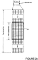
- the transmitted downlink signal thus comprises N BW subcarriers for a duration of N symb OFDM symbols. It can be represented by a resource grid as illustrated in Figure 2b . Each box in the grid represents a single sub-carrier for one symbol period and is referred to as a resource element.
- each PRB 21 is formed from 12 consecutive sub-carriers and (in this case) seven symbols for each subcarrier; although in practice the same allocations are made in the second slot 17 of each sub-frame 15 as well.
- the base station 5 transmits a PDCCH 23 (Physical Downlink Control Channel) over the first three symbols.
- the remaining symbols form the PDSCH 25 (Physical Downlink Shared CHannel) which is used to carry the downlink user data for the mobile telephones 3.
- the PDCCH channel includes, among other things, data for each of the mobile telephones 3, indicating if the mobile telephone 3 is scheduled for receiving downlink data in that sub-frame or is scheduled for uplink transmission in that sub-frame; and if so, data identifying the PRBs to be used for receiving the downlink data or for transmitting the uplink data.
- each of the sub-bands will at least be similar in structure to the LTE structure discussed above.
- the sub-carriers for each sub-band will be modulated onto a separate component carrier so that the transmitted sub-bands are contiguous or non-contiguous with each other. This is known as carrier aggregation and is schematically illustrated in Figure 3 for five sub-bands 25-1 to 25-5, each being 20 MHz wide, giving a total system bandwidth of 100 MHz.
- carrier aggregation is schematically illustrated in Figure 3 for five sub-bands 25-1 to 25-5, each being 20 MHz wide, giving a total system bandwidth of 100 MHz.
- the terms sub-band and component carrier will be used interchangeably.
- LTE-Advanced mobile telephones 3 will support bandwidths up to 100 MHz, they may not transmit/receive in the whole spectrum at any given time.
- the system is preferably arranged so that the mobile telephones 3 monitor one or a subset of the component carriers to start with; and then the base station scheduler, based on the activity of the mobile telephone 3, can direct the mobile telephone 3 to monitor a different (although perhaps overlapping) subset of the component carriers.
- sub-bands 25 are configured as LTE Rel 8 compatible, then full system information and paging would be broadcast on each component carrier. However the inventor considers this to be a waste of system resources. The inventor has realised that since all these component carriers belong to one cell (of base station 5) there is no real benefit in putting the paging and broadcast information in each of the component carriers (sub-bands 25). The inventor therefore proposes that only one or a subset of the component carriers in the cell should carry broadcast and paging information. In this exemplary embodiment, one component carrier (sub-band 25) carries this system information and it will be referred to as the anchor or primary carrier component.
- sub-band 25-3 is the anchor carrier component and it carries the broadcast and paging information for the cell.
- all mobile telephones 3 will camp on this anchor carrier component when in the Idle mode and will read the system and paging information from it.
- Release 8 mobile telephones 3 will only be scheduled on one of the anchor carrier components as they will have the same structure as defined for LTE Release 8.
- LTE-Advanced mobile telephone 3 since it will be camped on the anchor carrier component of the cell when Idle, the inventor proposes that such a mobile telephone 3 would initiate the RRC Connection Establishment Procedure on the anchor carrier component when it wants to make a connection (for example to make a call).
- the base station 5 can then instruct the mobile telephone 3 to move to one or more different component carriers at a suitable instance. This helps in balancing the load among the different component carriers within the cell and reduces battery consumption in the mobile telephone 3 as the mobile telephone only has to monitor a subset of the carrier components together with the anchor carrier component.
- the base station 5 can signal which of the component carriers the mobile telephone 3 should monitor and on which the mobile telephone 3 should transmit/receive data, by:
- IE Information Element
- PDCCH Signalling Signalling a mobile telephone 3 which component carrier it should monitor through PDCCH is the fastest technique. However, it is also the most unreliable (as no acknowledgement is sent by the mobile telephone 3 back to the base station 3 to acknowledge receipt of the information).
- PDCCH signalling can be achieved by signalling a special PDCCH format with a 5-bit bitmap indication for each mobile telephone 3 in sub-frame (n-1), indicating that the mobile telephone 3 should start listening to the component carriers for which the bit is set to "1" from sub-frame (n) onwards, until a further change is signalled.
- MAC Signalling Signalling each mobile telephone 3 which component carriers it should monitor through a MAC Control element is fast and fairly reliable. It could be achieved, for example, by having an IE in the DRX Command MAC Control Element, with a 5-bit bitmap indication for each mobile telephone 3, indicating that the mobile telephone 3 should start listening to the corresponding component carriers for which the bit is set to "1". The base station 5 can then assume that the mobile telephone 3 has applied the new configuration once it has received the acknowledgement that the mobile telephone 3 has received the DRX Command MAC Control Element.
- RRC Signalling RRC layer Signalling each mobile telephone 3 which component carriers it should monitor through an RRC message would be slow but very reliable. However, as the component carriers that a mobile telephone 3 may monitor might change frequently, RRC signaling is not preferred for this purpose.
- MAC Signalling is used for indicating to each mobile telephone 3 which component carriers it should monitor. As they will not monitor or transmit/receive data on the other component carriers, LTE-Advanced mobile telephones 3 can switch off their transceiver circuitry for the component carriers they will not monitor.
- each mobile telephone 3 can be configured to receive and/or transmit data in discontinuous time periods, the duration and frequency of which are controlled by the base station 5.
- This discontinuous reception/transmission is called DRX/DTX and allows the mobile telephone 3 to turn off its transceiver circuitry during the periods when it is not supposed to receive data from and/or transmit data to the base station 5, thereby reducing power consumption.
- the base station 5 defines the DRX pattern such that the mobile telephone 3 remains awake for the on-duration and monitors PDCCH and then goes to sleep. This concept is illustrated in Figure 4 .
- the mobile telephone 3 When the mobile telephone's activity increases, the mobile telephone 3 will start transmitting/receiving on an increased number of component carriers but the "On duration" would remain unchanged. If the mobile telephone 3 is already transmitting/receiving on on all the component carriers and if there is a further increase in activity, then the base station 5 can increase the On-duration defined for that mobile telephone 3.
- Alternative 2 Another alternative is to have one DRX configuration per component carrier (On Duration, DRX Cycle).
- the mobile telephone 3 would perform a Boolean "OR" of the DRX configurations for all the component carriers to determine the overall DRX pattern - defining when the mobile telephone 3 should be awake and asleep; and would use the individual DRX configurations to control the switching off of the transceiver circuitry for the non-monitored component carriers during the awake periods.
- battery savings in the mobile telephone 3 will be less with this alternative if the DRX cycles and the starting instances of the On Durations for the component carriers are not time aligned.
- a better way would be to have the same DRX cycle for all component carriers but with different On Durations. This would also work if the DRX cycle for one or more of the component carriers is an integer multiple of the DRX cycle of the other component carriers.
- FIG. 5 is a block diagram illustrating the main components of each of the base stations 5 shown in Figure 1 .
- each base station 5 includes transceiver circuit 31 which is operable to transmit signals to and to receive signals from the mobile telephones 3 via one or more antennas 33 and which is operable to transmit signals to and to receive signals from the telephone network 7 via a network interface 35.
- a controller 37 controls the operation of the transceiver circuit 31 in accordance with software stored in a memory 39.
- the software includes, among other things, an operating system 41 and a communications control module 43 having a resource allocation module 45 and a scheduler module 47.
- the communications control module 43 is operable to control the generation of the sub-frames in the different sub-bands 25 in which the uplink and downlink data is transmitted from/to the mobile telephones 3.
- the resource allocation module 45 is operable for allocating the resource blocks in the different sub-bands 25 to be used by the transceiver circuit 31 in its communications with each of the mobile telephones 3, depending on the amount of data to be transmitted between the base station 5 and the mobile telephones 3.
- the scheduler module 47 is operable to schedule the times for the transmission of the downlink data to the mobile telephones 3 and the times for the mobile telephone 3 to transmit its uplink data to the base station 5.
- the communications control module 43 is responsible for signalling, to each of the mobile telephones 3, data identifying which component carriers the mobile telephone should be monitoring when in the Idle mode; and for moving the mobile telephones 3 between the different component carriers when in RRC Connected mode; and for defining the DRX patterns used for controlling the times when the mobile telephones 3 can switch off its transceiver circuitry.
- FIG 6 is a block diagram illustrating the main components of each of the mobile telephones 3 shown in Figure 1 .
- the mobile telephones 3 include transceiver circuit 71 that is operable to transmit signals to and to receive signals from the base station 5 via one or more antennas 73.
- the mobile telephone 3 also includes a controller 75 which controls the operation of the mobile telephone 3 and which is connected to the transceiver circuit 71 and to a loudspeaker 77, a microphone 79, a display 81, and a keypad 83.
- the controller 75 operates in accordance with software instructions stored within a memory 85.
- these software instructions include, among other things, an operating system 87 and a communications control module 89 that includes a resource allocation module 91 and a transceiver control module 93.
- the communications control module 89 is operable to control communications with the base station 5 and during the Idle mode monitors the anchor component carrier 25-3.
- the resource allocation module is responsible for identifying the resources on which uplink should be transmitted and on which downlink data is to be received in the different sub-bands 25.
- the transceiver control module 93 is responsible for identifying the parts of the transceiver circuit 71 that can be switched off at the current instance using, for example, DRX configuration data received from the base station 5 or using knowledge of the sub-bands 25 that the mobile telephone 3 is to monitor.
- the base station 5 and the mobile telephones 3 are described for ease of understanding as having a number of discrete modules (such as the resource allocation modules, scheduler module, transceiver control module etc). Whilst these modules may be provided in this way for certain applications, for example where an existing system has been modified to implement the invention, in other applications, for example in systems designed with the inventive features in mind from the outset, these modules may be built into the overall operating system or code and so these modules may not be discernible as discrete entities.
- LTE-Advanced mobile telephones 3 have transceiver circuit 71 that can transmit and receive data on a number of different component carriers.
- Figure 7 is a block diagram illustrating suitable transceiver circuit 71 that may be used.
- the transceiver circuit 71 includes five up-converter/down-converter circuits 95-1 to 95-5, one for each of the five sub-bands 25, for modulating and demodulating the sub-carriers onto the corresponding component carrier (C1 to C5).
- the transceiver circuit 71 also includes five encoding/decoding circuits 97-1 to 97-5 for encoding and decoding the uplink data and downlink data respectively in each of the five sub-bands 25.
- the encoding/decoding circuits 97 receive the uplink data from, and pass the decoded downlink data to, the controller 75.
- the controller 75 also supplies individual power control signals (via the dashed signal lines) to the encoding/decoding circuits 97 and to the up-converter circuits 95, so that individual circuits can be powered down when not needed and so that they can all be powered down when none of the circuits are needed (for example when the mobile telephone 3 enters its sleep mode).
- the base stations and the mobile telephones can be considered as communications nodes or devices which communicate with each other.
- Other communications nodes or devices may include user devices such as, for example, personal digital assistants, laptop computers, web browsers, etc.
- the software modules may be provided in compiled or un-compiled form and may be supplied to the base station or to the mobile telephone as a signal over a computer network, or on a recording medium. Further, the functionality performed by part or all of this software may be performed using one or more dedicated hardware circuits. However, the use of software modules is preferred as it facilitates the updating of base station 5 and the mobile telephones 3 in order to update their functionalities. Similarly, although the above embodiments employed transceiver circuitry, at least some of the functionality of the transceiver circuitry can be performed by software.
- a new PDCCH structure is needed to address up to 100 MHz of aggregated system bandwidth.
- Two different approaches, separate PDCCH for each carrier and common PDCCH for multiple carriers, are under consideration in RAN 1.
- One of the methods will be agreed to be adopted for LTE Advance System. Irrespective of this decision, at any given point in time the UE may not transmit or receive data on all the component carriers.
- eNB scheduler should have the flexibility to schedule a UE in any of the component carrier it wishes and should be able to move it around. The UE on the other hand should know in advance which subset of the component carriers it should monitor and turn of the RF for the others. This would result in considerable power savings in UEs.
- LTE Advance system we would see Carrier aggregation, where two or more component carriers are aggregated in order to support wider transmission bandwidths e.g. up to 100MHz and for spectrum aggregation. These carrier aggregations could be contiguous or non-contiguous. Although LTE Advanced UEs will support 100 MHz BW however it may not transmit/receive in the whole spectrum at any given time. In order to enable the UE to save battery power it would be wise that the UE listens to only some of the component carriers to start with and then the eNB scheduler, based on the activity of the UE can direct it to monitor subset of component carriers.
- Proposal 2 There should be a mechanism available through which the UE should be moved around the different component carriers.
- Signalling of which component carriers the UE will monitor and transmit/receive the data on can be done by
- PDCCH Signalling Signalling the UE which component carrier it should monitor through PDCCH is the fastest although it is unreliable.
- MAC Signalling Signalling the UE which component carrier it should monitor through MAC Control element is fast and fairly reliable. We could have an IE in the DRX Command MAC Control Element with 5 bits bitmap indication to the UE that it should start listening to the component carriers for which the bit is set to 1. eNB will assume that the UE has applied the new configuration after it has received the acknowledgement from the UE.
- RRC Signalling RRC layer Signalling the UE which component carrier it should monitor through in a RRC message would be slow and although very reliable. As the component carriers a UE may monitor may change frequently RRC signaling may not be a suited for this purpose.
- Proposal 3 MAC Signalling be used to indicate to the UE which carrier component it should monitor
- Proposal 4 UE could be configured to monitor the Anchor Carrier and a subset of the carriers.
- Rel 8 we have a DRX defined such that the UE remains awake for the on-duration and monitors PDCCH and then goes to sleep. This concept is shown in Figure 4 .
- the UE When the UE activity increases, the UE will start transmitting/receiving on the increased number of component carriers but the On duration would remain unchanged. If UE is already transmitting/ receiving on on all the component carriers and if there is a further increase in the activity, the on-duration will be increased.
- Alternative 2 Another general alternative is to have the one DRX configuration per component carrier (On Duration, DRX Cycle) and the UE "ORs" the DRX configuration per component carrier to determine other the overall DRX pattern.
- battery savings in the UE will be less in case DRX Cycles and the starting instance of the On Duration of the comnponent carriers are not aligned.
- a better way would be to have the same DRX cycle on all component carrier with a different on duration.
- DRX cycle in one component carrier could be a integral multiple of DRX cycle on the other component carrier.
Landscapes
- Engineering & Computer Science (AREA)
- Signal Processing (AREA)
- Computer Networks & Wireless Communication (AREA)
- Computer Security & Cryptography (AREA)
- Mobile Radio Communication Systems (AREA)
Description
- The present invention relates to communications devices, particularly but not exclusively devices operating according to the 3GPP standards or equivalents or derivatives thereof. The invention has particular but not exclusive relevance to the impacts of carrier aggregation that is to be used in LTE-Advanced as currently defined in 3GPP standards documentation TR 36.814.
- With LTE Rel 8, a transmission band of 20MHz was defined. In LTE-Advanced carrier aggregation will be used to support system bandwidths up to 100 MHz. This involves splitting the system bandwidth into five 20 MHz sub-bands, each centred on a respective component carrier. In order to be backwards compatible with LTE Rel 8 User Equipment (UEs), at least one of those sub-bands has to be LTE Rel 8 compliant.
- To support carrier aggregation a new Physical Downlink Control Channel (PDCCH) structure is needed to address the aggregated system bandwidth of up to 100 MHz. Two different approaches, separate PDCCH for each carrier and common PDCCH for multiple carriers, are under consideration in
RAN 1. One of these two methods will be agreed to be adopted for the LTE-Advanced System. Irrespective of this decision, at any given point in time the UE may not transmit or receive data on all the component carriers. The base station (referred to as the eNB in LTE documentation) should have the flexibility to schedule a UE on any of the component carriers it wishes and should be able to move the UE on to different component carriers as required. The UE on the other hand should know in advance which subset of the component carriers it should monitor and turn off its RF transceiver circuitry for the others. This would result in considerable power savings in the UE. - 3GPP publication No. R2-092411 titled "Discussions on Carrier Aggregation in RAN2" discloses that two component carrier types were considered for LTE-A and that the benefits of introducing an anchor component carrier have been discussed. However, is not decided yet what functions should be provided by the anchor component carrier.
- 3GPP publication No. R2-092180 titled "RAN2 considerations for carrier aggregation" discloses further details of the impact of carrier aggregation on 3GPP RAN2. It is disclosed therein that there are two type of CA: contiguous CA and non-contiguous CA and that these different types of CA will form different deployment and that, in order to support CA with multiple layers with different coverage, efficient procedures and measurements are needed to manage usage of component carriers, management of an active carrier set, etc.
- 3GPP TS 36.321 V8.5.0 discloses the E-UTRA MAC protocol specifications.
- 3GPP publication No. R1-090359 titled "Multicarrier Control for LTE-Advanced" discusses the benefits of introducing multicarrier DL and UL assignments in LTE-Advanced. The multicarrier assignments are considered more suitable for multicarrier configuration as they can provide overhead reduction compared to single carrier assignments and possibly reduce the UE assignment monitoring to one carrier.
- 3GPP publication No. R1-090860 titled "Notion of Anchor Carrier in LTE-A" discusses the definition of anchor and non-anchor component carriers to reduce the overhead as the system information, synchronization and paging for a certain cell would be provided on anchor carriers only.
-
EP2480037A1 discloses multiple downlink (DL) and uplink (UL) carriers for wireless communication between nodes and user equipment (UE) and, among the carriers, designated carriers to provide synchronization, system information, paging, data and control for multicarrier enabled UEs. - 3GPP publication No. R1-082468 titled "Carrier aggregation in LTE-Advanced" discusses carrier aggregation, in LTE-Advanced, to support a wider bandwidth than in LTE Rel-8, up to 100 MHz.
- 3GPP publication No R1-090628 titled "Downlink control structure for LTE-A2" discloses one transport block and one HARQ entity per scheduled component carrier, and a UE which may receive multiple component carriers simultaneously.
- 3GPP publication No Rl-091200 titled "Component carrier types and the corresponding characteristics" discloses that in LTE-Advanced, a cell may consist of multiple component carriers to extend its transmission/reception bandwidth to be larger than that of LTE Rel-8. A rough categorization and definition of the various types of CCs in such a system are discussed.
- The present invention provides a simple mechanism by which the eNB scheduler can switch the UE among the different component carriers.
- According to one exemplary aspect, the present invention provides a base station comprising: a transceiver operable to transmit downlink data to a user equipment, UE, (3) and to receive uplink data from the UE using a plurality of component carriers; and a controller operable to control the transceiver to transmit broadcast and paging channels on a primary subset of said component carriers but not on another subset of the component carriers; and cause the transceiver to transmit control data to the UE instructing the UE to monitor one or more component carriers in the other subset of component carriers, wherein the control data comprises a MAC control element comprising a bitmap indication indicating that the UE should monitor one or more corresponding component carrier for which a bit is set to "1". This may be in addition to or instead of monitoring component carriers in the anchor subset. The controller may also transmit DRX control data to the UE to cause the UE to switch off transceiver circuits for component carriers that it has not been instructed to monitor. The controller may transmit the control data within a MAC layer communication message as this is fast and relatively reliable compared with RRC layer signalling.
- The controller may receive a connection request from the UE on a component carrier belonging to the primary subset and in response transmits downlink data for the UE on a different component carrier. Before sending the downlink data, the controller would inform the remote user equipment, UE, of the component carriers it will use to carry the downlink data.
- The present invention also provides a UE comprising: a transceiver operable to transmit uplink data to a base station and to receive downlink data from the base station on a plurality of component carriers, wherein a primary subset of the component carriers include broadcast and paging channels; and a controller operable to: control the transceiver, during an idle mode, to cause the UE to camp on one or more of the component carriers in the primary subset; and control the transceiver to receive control data from the base station instructing the UE to monitor one or more component carriers in another subset of the component carriers, wherein the control data comprises a MAC control element comprising a bitmap indication indicating that the UE should monitor one or more corresponding component carriers for which a bit is set to "1" and wherein the controller is operable to control the transceiver to monitor the one or more component carriers in the other subset.
- When the user equipment wishes to make a connection, for example, to make a call, the controller may control the transceiver to transmit a connection request on the component carrier on which the UE is camped and may control the receiver to receive downlink data from the base station on a different component carrier that the UE has been instructed to monitor.
- Also disclosed is a communications device comprising: a transceiver operable to transmit downlink data to and to receive uplink data from a remote communications device using a subset of component carriers; and a controller operable to control the transceiver so that: i) during a first interval the communications device is operable to communicate with the remote communications device on a first subset of component carriers; ii) the communications device transmits control data to the remote communications device using the first subset of component carriers, the control data instructing the remote communications device to communicate with the communications device using a second subset of component carriers; and iii) during a second interval the communications device is operable to communicate with the remote communications device on the second subset of component carriers.
- Also disclosed is a communications device comprising: a transceiver operable to transmit uplink data to and to receive downlink data from a remote communications device using a subset of component carriers; and a controller operable to: i) control the transceiver so that during a first interval the communications device is operable to communicate with the remote communications device on a first subset of component carriers; ii) receive control data from the remote communications device using the first subset of component carriers, the control data instructing the communications device to communicate with the remote communications device using a second subset of component carriers; and iii) control the transceiver so that during a second interval the communications device is operable to communicate with the remote communications device on the second subset of component carriers.
- The invention provides a computer program product according to claim 9.
- An exemplary embodiment of the invention will now be described, by way of example, with reference to the accompanying drawings in which:
-
-
Figure 1 schematically illustrates a mobile telecommunication system of a type to which the invention is applicable; -
Figure 2a schematically illustrates a generic frame structure used in communications over the wireless links of the system shown inFigure 1 ; -
Figure 2b schematically illustrates the way in which the frequency subcarriers are divided into resource blocks and the way that a time slot is divided into a number of OFDM symbols; -
Figure 3 schematically illustrates the way in which carrier aggregation is used to provide a system bandwidth of up to 100 MHz; -
Figure 4 illustrates a DRX timing pattern generated by the base station for a mobile telephone and used to control when the mobile telephone is asleep and awake; -
Figure 5 schematically illustrates a base station forming part of the system shown inFigure 1 ; -
Figure 6 schematically illustrates a mobile telephone forming part of the system shown inFigure 1 ; and -
Figure 7 is a block diagram illustrating the main components of transceiver circuitry forming part of the mobile telephone shown inFigure 6 . -
Figure 1 schematically illustrates a mobile (cellular)telecommunication system 1 in which users of mobile telephones (MT) 3-0, 3-1, and 3-2 can communicate with other users (not shown) via one of the base stations 5-1 or 5-2 and atelephone network 7. A number of uplink and downlink communications resources (sub-carriers, time slots etc) are available for the wireless link between themobile telephones 3 and thebase stations 5. In this exemplary embodiment, thebase stations 5 allocate downlink resources to eachmobile telephone 3 depending on the amount of data to be sent to themobile telephone 3. Similarly, thebase stations 5 allocate uplink resources to eachmobile telephone 3 depending on the amount and type of data themobile telephone 3 has to send to thebase station 5. - In this exemplary embodiment, the system bandwidth is divided into five 20 MHz sub-bands, each being carried by a respective component carrier. The
base station 5 is operable to allocated resources for eachmobile telephone 3 on one or more of the component carriers, depending on the capability of themobile telephone 3 concerned and the amount of data to be transmitted between thebase station 5 and thatmobile telephone 3. Themobile telephones 3 have transceiver circuitry that can receive and transmit signals on the different component carriers and when themobile telephone 3 is not scheduled to use a particular component carrier, it can power down the corresponding transceiver circuitry to conserve battery power. - Before discussing the specific ways in which the
base station 5 schedules the differentmobile telephones 3, a description will be given of the access scheme and a general frame structure agreed for LTE Rel 8. An Orthogonal Frequency Division Multiple Access (OFDMA) technique is used for the downlink to allow themobile telephones 3 to receive data over the air interface with thebase station 5. Different sub-carriers are allocated by the base station 5 (for a predetermined amount of time) to eachmobile telephone 3 depending on the amount of data to be sent to themobile telephone 3. These are referred to as physical resource blocks (PRBs) in the LTE specifications. PRBs thus have a time and frequency dimension. To do this, thebase station 5 dynamically allocates PRBs for each device that it is serving and signals the allocations for each sub-frame (TTI) to each of the scheduledmobile telephones 3 in a control channel. -
Figure 2a illustrates a generic frame structure agreed for LTE Rel 8 communications over the air interface with thebase station 5. As shown, oneframe 13 is 10 msec long and comprises tensub-frames 15 of 1 msec duration (known as a Transmission Time Interval (TTI)). Each sub-frame or TTI comprises twoslots 17 of 0.5 msec duration. Eachslot 17 comprises either six or sevenOFDM symbols 19, depending on whether the normal or extended cyclic prefix (CP) is employed. The total number of available sub-carriers depends on the overall transmission bandwidth of the system. The LTE specifications define parameters for system bandwidths from 1.4 MHz to 20 MHz and one PRB is currently defined to comprise 12 consecutive subcarriers for oneslot 17. A PRB over two slots is also defined by the LTE specifications as being the smallest element of resource allocation assigned by the base station scheduler. These sub-carriers are then modulated onto a component carrier to up-convert the signal to the desired transmission bandwidth. The transmitted downlink signal thus comprises NBW subcarriers for a duration of Nsymb OFDM symbols. It can be represented by a resource grid as illustrated inFigure 2b . Each box in the grid represents a single sub-carrier for one symbol period and is referred to as a resource element. As shown, eachPRB 21 is formed from 12 consecutive sub-carriers and (in this case) seven symbols for each subcarrier; although in practice the same allocations are made in thesecond slot 17 of each sub-frame 15 as well. - At the start of each sub-frame 15, the
base station 5 transmits a PDCCH 23 (Physical Downlink Control Channel) over the first three symbols. The remaining symbols form the PDSCH 25 (Physical Downlink Shared CHannel) which is used to carry the downlink user data for themobile telephones 3. The PDCCH channel includes, among other things, data for each of themobile telephones 3, indicating if themobile telephone 3 is scheduled for receiving downlink data in that sub-frame or is scheduled for uplink transmission in that sub-frame; and if so, data identifying the PRBs to be used for receiving the downlink data or for transmitting the uplink data. - In the proposed LTE-Advanced system, a number of separate sub-bands will be provided in order to support wider transmission bandwidths, each of the sub-bands will at least be similar in structure to the LTE structure discussed above. The sub-carriers for each sub-band will be modulated onto a separate component carrier so that the transmitted sub-bands are contiguous or non-contiguous with each other. This is known as carrier aggregation and is schematically illustrated in
Figure 3 for five sub-bands 25-1 to 25-5, each being 20 MHz wide, giving a total system bandwidth of 100 MHz. In the following description, the terms sub-band and component carrier will be used interchangeably. - Although LTE-Advanced
mobile telephones 3 will support bandwidths up to 100 MHz, they may not transmit/receive in the whole spectrum at any given time. In order to allow themobile telephones 3 to save battery power the system is preferably arranged so that themobile telephones 3 monitor one or a subset of the component carriers to start with; and then the base station scheduler, based on the activity of themobile telephone 3, can direct themobile telephone 3 to monitor a different (although perhaps overlapping) subset of the component carriers. - If all component carriers (sub-bands 25) are configured as LTE Rel 8 compatible, then full system information and paging would be broadcast on each component carrier. However the inventor considers this to be a waste of system resources. The inventor has realised that since all these component carriers belong to one cell (of base station 5) there is no real benefit in putting the paging and broadcast information in each of the component carriers (sub-bands 25). The inventor therefore proposes that only one or a subset of the component carriers in the cell should carry broadcast and paging information. In this exemplary embodiment, one component carrier (sub-band 25) carries this system information and it will be referred to as the anchor or primary carrier component. This is illustrated in
Figure 3 , which shows that sub-band 25-3 is the anchor carrier component and it carries the broadcast and paging information for the cell. Thus, allmobile telephones 3 will camp on this anchor carrier component when in the Idle mode and will read the system and paging information from it. - Release 8
mobile telephones 3 will only be scheduled on one of the anchor carrier components as they will have the same structure as defined for LTE Release 8. For an LTE-Advancedmobile telephone 3, since it will be camped on the anchor carrier component of the cell when Idle, the inventor proposes that such amobile telephone 3 would initiate the RRC Connection Establishment Procedure on the anchor carrier component when it wants to make a connection (for example to make a call). Once the RRC Connection or an EPS bearer is established, thebase station 5 can then instruct themobile telephone 3 to move to one or more different component carriers at a suitable instance. This helps in balancing the load among the different component carriers within the cell and reduces battery consumption in themobile telephone 3 as the mobile telephone only has to monitor a subset of the carrier components together with the anchor carrier component. - The
base station 5 can signal which of the component carriers themobile telephone 3 should monitor and on which themobile telephone 3 should transmit/receive data, by: - PDCCH Signalling
- MAC Signalling
- RRC Signalling.
- In all three cases an Information Element (IE) will be needed that will be 5 bits long, with each bit corresponding to one of the component carriers and identifying whether or not the
mobile telephone 3 should monitor the corresponding component carrier. - PDCCH Signalling: Signalling a
mobile telephone 3 which component carrier it should monitor through PDCCH is the fastest technique. However, it is also the most unreliable (as no acknowledgement is sent by themobile telephone 3 back to thebase station 3 to acknowledge receipt of the information). PDCCH signalling can be achieved by signalling a special PDCCH format with a 5-bit bitmap indication for eachmobile telephone 3 in sub-frame (n-1), indicating that themobile telephone 3 should start listening to the component carriers for which the bit is set to "1" from sub-frame (n) onwards, until a further change is signalled. - MAC Signalling: Signalling each
mobile telephone 3 which component carriers it should monitor through a MAC Control element is fast and fairly reliable. It could be achieved, for example, by having an IE in the DRX Command MAC Control Element, with a 5-bit bitmap indication for eachmobile telephone 3, indicating that themobile telephone 3 should start listening to the corresponding component carriers for which the bit is set to "1". Thebase station 5 can then assume that themobile telephone 3 has applied the new configuration once it has received the acknowledgement that themobile telephone 3 has received the DRX Command MAC Control Element. - RRC Signalling: RRC layer Signalling each
mobile telephone 3 which component carriers it should monitor through an RRC message would be slow but very reliable. However, as the component carriers that amobile telephone 3 may monitor might change frequently, RRC signaling is not preferred for this purpose. - Therefore, in this embodiment, MAC Signalling is used for indicating to each
mobile telephone 3 which component carriers it should monitor. As they will not monitor or transmit/receive data on the other component carriers, LTE-Advancedmobile telephones 3 can switch off their transceiver circuitry for the component carriers they will not monitor. - In LTE Rel 8, each
mobile telephone 3 can be configured to receive and/or transmit data in discontinuous time periods, the duration and frequency of which are controlled by thebase station 5. This discontinuous reception/transmission is called DRX/DTX and allows themobile telephone 3 to turn off its transceiver circuitry during the periods when it is not supposed to receive data from and/or transmit data to thebase station 5, thereby reducing power consumption. Thebase station 5 defines the DRX pattern such that themobile telephone 3 remains awake for the on-duration and monitors PDCCH and then goes to sleep. This concept is illustrated inFigure 4 . - A similar although more complex DRX procedure can be used to control LTE-Advanced
mobile telephones 3 so that they switch off their transciever circuitry for component carriers they are not monitoring even during the defined "On-Duration". Indeed there are two possible ways of configuring DRX for LTE-Advanced mobile telephones. - Alternative 1: The same basic LTE Rel-8 mechanism is used for LTE-Advanced, with certain modifications to keep the system simple and backwards compatible. In particular, a two level DRX configuration can be used. On the fiirst level one DRX configuration (On Duration, DRX Cycle) is configured by the RRC layer of the
base station 5 for the mobile telephone 3 (identical to what is defined for LTE Rel 8). On the second level, during the "On-Duration" themobile telephone 3 will monitor the component carriers indicated by the MAC control element (DRX Command MAC Control Element). Hence even during the on-duration the UE will monitor only those carriers that are actually needed to be monitored and can switch off its transceiver circuitry for reveiving the other carriers. This will provide considerable savings in battery life. - When the mobile telephone's activity increases, the
mobile telephone 3 will start transmitting/receiving on an increased number of component carriers but the "On duration" would remain unchanged. If themobile telephone 3 is already transmitting/receiving on on all the component carriers and if there is a further increase in activity, then thebase station 5 can increase the On-duration defined for thatmobile telephone 3. - Alternative 2: Another alternative is to have one DRX configuration per component carrier (On Duration, DRX Cycle). In this case the
mobile telephone 3 would perform a Boolean "OR" of the DRX configurations for all the component carriers to determine the overall DRX pattern - defining when themobile telephone 3 should be awake and asleep; and would use the individual DRX configurations to control the switching off of the transceiver circuitry for the non-monitored component carriers during the awake periods. However, battery savings in themobile telephone 3 will be less with this alternative if the DRX cycles and the starting instances of the On Durations for the component carriers are not time aligned. Hence a better way would be to have the same DRX cycle for all component carriers but with different On Durations. This would also work if the DRX cycle for one or more of the component carriers is an integer multiple of the DRX cycle of the other component carriers. -
Figure 5 is a block diagram illustrating the main components of each of thebase stations 5 shown inFigure 1 . As shown, eachbase station 5 includestransceiver circuit 31 which is operable to transmit signals to and to receive signals from themobile telephones 3 via one ormore antennas 33 and which is operable to transmit signals to and to receive signals from thetelephone network 7 via anetwork interface 35. Acontroller 37 controls the operation of thetransceiver circuit 31 in accordance with software stored in amemory 39. The software includes, among other things, anoperating system 41 and acommunications control module 43 having aresource allocation module 45 and ascheduler module 47. Thecommunications control module 43 is operable to control the generation of the sub-frames in the different sub-bands 25 in which the uplink and downlink data is transmitted from/to themobile telephones 3. Theresource allocation module 45 is operable for allocating the resource blocks in the different sub-bands 25 to be used by thetransceiver circuit 31 in its communications with each of themobile telephones 3, depending on the amount of data to be transmitted between thebase station 5 and themobile telephones 3. Thescheduler module 47 is operable to schedule the times for the transmission of the downlink data to themobile telephones 3 and the times for themobile telephone 3 to transmit its uplink data to thebase station 5. Thecommunications control module 43 is responsible for signalling, to each of themobile telephones 3, data identifying which component carriers the mobile telephone should be monitoring when in the Idle mode; and for moving themobile telephones 3 between the different component carriers when in RRC Connected mode; and for defining the DRX patterns used for controlling the times when themobile telephones 3 can switch off its transceiver circuitry. -
Figure 6 is a block diagram illustrating the main components of each of themobile telephones 3 shown inFigure 1 . As shown, themobile telephones 3 includetransceiver circuit 71 that is operable to transmit signals to and to receive signals from thebase station 5 via one ormore antennas 73. As shown, themobile telephone 3 also includes acontroller 75 which controls the operation of themobile telephone 3 and which is connected to thetransceiver circuit 71 and to aloudspeaker 77, amicrophone 79, adisplay 81, and akeypad 83. Thecontroller 75 operates in accordance with software instructions stored within amemory 85. As shown, these software instructions include, among other things, anoperating system 87 and acommunications control module 89 that includes aresource allocation module 91 and atransceiver control module 93. Thecommunications control module 89 is operable to control communications with thebase station 5 and during the Idle mode monitors the anchor component carrier 25-3. The resource allocation module is responsible for identifying the resources on which uplink should be transmitted and on which downlink data is to be received in the different sub-bands 25. Thetransceiver control module 93 is responsible for identifying the parts of thetransceiver circuit 71 that can be switched off at the current instance using, for example, DRX configuration data received from thebase station 5 or using knowledge of the sub-bands 25 that themobile telephone 3 is to monitor. - In the above description, the
base station 5 and themobile telephones 3 are described for ease of understanding as having a number of discrete modules (such as the resource allocation modules, scheduler module, transceiver control module etc). Whilst these modules may be provided in this way for certain applications, for example where an existing system has been modified to implement the invention, in other applications, for example in systems designed with the inventive features in mind from the outset, these modules may be built into the overall operating system or code and so these modules may not be discernible as discrete entities. - As mentioned above, LTE-Advanced
mobile telephones 3 havetransceiver circuit 71 that can transmit and receive data on a number of different component carriers.Figure 7 is a block diagram illustratingsuitable transceiver circuit 71 that may be used. As shown, thetransceiver circuit 71 includes five up-converter/down-converter circuits 95-1 to 95-5, one for each of the five sub-bands 25, for modulating and demodulating the sub-carriers onto the corresponding component carrier (C1 to C5). Thetransceiver circuit 71 also includes five encoding/decoding circuits 97-1 to 97-5 for encoding and decoding the uplink data and downlink data respectively in each of the five sub-bands 25. The encoding/decoding circuits 97 receive the uplink data from, and pass the decoded downlink data to, thecontroller 75. Thecontroller 75 also supplies individual power control signals (via the dashed signal lines) to the encoding/decoding circuits 97 and to the up-converter circuits 95, so that individual circuits can be powered down when not needed and so that they can all be powered down when none of the circuits are needed (for example when themobile telephone 3 enters its sleep mode). - A detailed embodiment has been described above. As those skilled in the art will appreciate, a number of modifications and alternatives falling within the scope of the claims can be made to the above embodiment. By way of illustration only a number of these alternatives and modifications will now be described.
- In the above embodiment, a mobile telephone based telecommunications system was described. As those skilled in the art will appreciate, the signalling and power control techniques described in the present application can be employed in any communications system. In the general case, the base stations and the mobile telephones can be considered as communications nodes or devices which communicate with each other. Other communications nodes or devices may include user devices such as, for example, personal digital assistants, laptop computers, web browsers, etc.
- In the above embodiments, a number of software modules were described. As those skilled will appreciate, the software modules may be provided in compiled or un-compiled form and may be supplied to the base station or to the mobile telephone as a signal over a computer network, or on a recording medium. Further, the functionality performed by part or all of this software may be performed using one or more dedicated hardware circuits. However, the use of software modules is preferred as it facilitates the updating of
base station 5 and themobile telephones 3 in order to update their functionalities. Similarly, although the above embodiments employed transceiver circuitry, at least some of the functionality of the transceiver circuitry can be performed by software. - Various other modifications will be apparent to those skilled in the art and will not be described in further detail here.
- The following is a detailed description of the way in which the present inventions may be implemented in the currently proposed 3GPP LTE standard. Whilst various features are described as being essential or necessary, this may only be the case for the proposed 3GPP LTE standard, for example due to other requirements imposed by the standard. These statements should not, therefore, be construed as limiting the present invention in any way.
- To support carrier aggregation a new PDCCH structure is needed to address up to 100 MHz of aggregated system bandwidth. Two different approaches, separate PDCCH for each carrier and common PDCCH for multiple carriers, are under consideration in
RAN 1. One of the methods will be agreed to be adopted for LTE Advance System. Irrespective of this decision, at any given point in time the UE may not transmit or receive data on all the component carriers. eNB scheduler should have the flexibility to schedule a UE in any of the component carrier it wishes and should be able to move it around. The UE on the other hand should know in advance which subset of the component carriers it should monitor and turn of the RF for the others. This would result in considerable power savings in UEs. - In this contribution we discuss the simple mechanism by which the eNB scheduler could switch the UE would among different component carriers.
- In LTE Advance system we would see Carrier aggregation, where two or more component carriers are aggregated in order to support wider transmission bandwidths e.g. up to 100MHz and for spectrum aggregation. These carrier aggregations could be contiguous or non-contiguous. Although LTE Advanced UEs will support 100 MHz BW however it may not transmit/receive in the whole spectrum at any given time. In order to enable the UE to save battery power it would be wise that the UE listens to only some of the component carriers to start with and then the eNB scheduler, based on the activity of the UE can direct it to monitor subset of component carriers.
- If all component carriers are configured as R8 compatible, the full system information and paging should be broadcast on each component carrier. However we see this as wastage of the resources. We think since all these component carrier belongs to one cell there may not be any benefit for putting the paging and broadcast information in each of the component carrier. We suggest that there should be only a subset of the component carrier in the cell that carries broadcast and paging information and we call this carrier component as the Anchor or Primary Carrier Component as shown in
Figure 3 . This would also mean that the Idle mode UE will camp on this Anchor Component and shall read the system and paging information from it. - Release 8 UE will only be scheduled on the Anchor Carriers as they have the same structure as the LTE Release 8.
- For Release 9, since the UE will be camped on the Anchor Carrier Component of the cell we would suggest that it would be logical that the UE would initiate RRC Connection Establishment Procedure on the Anchor Carrier Component. Once the RRC Connection or an EPS bearer is established the, UE shall be instructed by the network to move on to the different component carrier at a suitable instance. This will help in balancing the load among different carriers within the cell and reduction in UE battery consumption as the UE would only monitor a subset of the carrier components together with the anchor carrier component.
- Signalling of which component carriers the UE will monitor and transmit/receive the data on can be done by
- PDCCH Signalling
- MAC Signalling
- RRC Signalling.
- In all the three cases we would need an IE that would be 5 bit long with each bit corresponding to a component carrier which the UE should monitor.
- PDCCH Signalling: Signalling the UE which component carrier it should monitor through PDCCH is the fastest although it is unreliable. We could have a special PDCCH format with 5 bits bitmap indication to the UE in sub frame (n-1) that it should start listening to the component carriers for which the bit is set to 1 from sub frame n onwards until further change is signaled.
- MAC Signalling: Signalling the UE which component carrier it should monitor through MAC Control element is fast and fairly reliable. We could have an IE in the DRX Command MAC Control Element with 5 bits bitmap indication to the UE that it should start listening to the component carriers for which the bit is set to 1. eNB will assume that the UE has applied the new configuration after it has received the acknowledgement from the UE.
- RRC Signalling: RRC layer Signalling the UE which component carrier it should monitor through in a RRC message would be slow and although very reliable. As the component carriers a UE may monitor may change frequently RRC signaling may not be a suited for this purpose.
- Hence our preference would be to use MAC Signalling for indicating the UE which component carriers it should monitor.
- Further there is no point in the UE monitoring all the carriers as the UE would not be transmitting or receiving on these carriers. Moreover, since the retransmissions will be performed on the respective HARQ entities for each carrier, hence it makes sense that UE switches off the RF Circuitry of the Component carriers it is not monitoring.
- In Rel 8 we have a DRX defined such that the UE remains awake for the on-duration and monitors PDCCH and then goes to sleep. This concept is shown in
Figure 4 . - We can two possible ways of configuring DRX for LTE Advance.
- Alternative 1 : We can still keep the basic Rel-8 mechanism for LTE advance with certain modification and keep the system simple and backward compatible. We can have a 2 level DRX configuration in LTE. On the fiirst level we will have only one DRX configuration (On Duration, DRX Cycle) configured by RRC for the UE, identical to what we had it in Release 8. On the second level, during the "On-Duration" UE will monitor the carriers indicated by the MAC control element (DRX Command MAC Control Element). Hence even during the on-duration the UE will monitor only those carriers that are actually needed to be monitored and can switch off the RF Circuit for reveiving the other carriers. This will provide considerable saving in battery life.
- When the UE activity increases, the UE will start transmitting/receiving on the increased number of component carriers but the On duration would remain unchanged. If UE is already transmitting/ receiving on on all the component carriers and if there is a further increase in the activity, the on-duration will be increased.
- Alternative 2: Another general alternative is to have the one DRX configuration per component carrier (On Duration, DRX Cycle) and the UE "ORs" the DRX configuration per component carrier to determine other the overall DRX pattern. However, battery savings in the UE will be less in case DRX Cycles and the starting instance of the On Duration of the comnponent carriers are not aligned. Hence a better way would be to have the same DRX cycle on all component carrier with a different on duration.
- Also the DRX cycle in one component carrier could be a integral multiple of DRX cycle on the other component carrier.
- In this paper we discuss how the UE in the idle and connected mode be assigned to monitor a subset of carriers. The main proposal of the contribution are
- Proposal 1: Idle mode UE will camp on Anchor Component and shall read the system and paging information from it
- Proposal 2: There should be a mechanism available through which the UE should be moved around the different component carriers.
- Proposal 3: MAC Signalling be used to indicate to the UE which carrier component it should monitor
- Proposal 4: UE could be configured to monitor the Anchor Carrier and a subset of the carriers.
- We request
RAN 2 to discuss this and NEC would be happy to draft a text proposal for the TR to capture the agreements in the TR.
Claims (9)
- A base station comprising:a transceiver(31) operable to transmit downlink data to and to receive uplink data from a user equipment, UE, (3) using a plurality of component carriers; anda controller (37) operable to:control the transceiver (31) to transmit broadcast and paging channels on a primary subset of said component carriers but not on another subset of the component carriers; andcause the transceiver (31) to transmit control data to the UE instructing the UE to monitor one or more component carriers in the other subset of component carriers,wherein the control data comprises a MAC control element comprising a bitmap indication indicating that the UE should monitor one or more corresponding component carriers for which a bit is set to "1".
- A base station according to claim 1, wherein the controller (37) is operable to control the transceiver (31) to transmit DRX control data to the UE to cause the UE to switch off transceiver circuits for component carriers that it is not monitoring.
- A base station according to claim 1 or 2, wherein the controller (37) is operable to control the transceiver (31) to receive a connection request from the UE on a component carrier of said primary subset and is operable to control the transceiver (31) to transmit downlink data for the UE on a different component carrier.
- A user equipment, UE, comprising:a transceiver (71) operable to transmit uplink data to and to receive downlink data from a base station on a plurality of component carriers, wherein a primary subset of the component carriers include broadcast and paging channels; anda controller (75) operable to:control the transceiver (71), during an idle mode, to cause the UE to camp on one or more of the component carriers in the primary subset; andcontrol the transceiver (71) to receive control data from the base station instructing the UE to monitor one or more component carriers in another subset of the component carriers, wherein the control data comprises a MAC control element comprising a bitmap indication indicating that the UE should monitor one or more corresponding component carriers for which a bit is set to "1" and wherein the controller (75) is operable to control the transceiver (71) to monitor the one or more component carriers in the other subset.
- A user equipment according to claim 4, wherein the controller (75) is operable to control the transceiver (71) to receive DRX control data from the base station and wherein the controller (75) is operable to use the received DRX control data to determine when to switch off parts of the transceiver (71) configured for component carriers that are not to be monitored, optionally wherein the DRX control data includes an ON duration and a DRC cycle, and wherein the controller (75) is operable to switch off parts of the transceiver (71) that are not to be monitored during the On durations defined by the DRX control data and/or optionally wherein said DRX control data includes control data in respect of each component carrier and defines times during which transceiver circuitry for the different component carriers can be switched off.
- A user equipment according to claim 5, wherein the controller (75) is operable to control the transceiver (71) to transmit a connection request on the component carrier on which the UE is camped and is operable to control the transceiver (71) to receive downlink data from the base station on a different component carrier that the UE has been instructed to monitor.
- A method performed by a base station comprising:transmitting downlink data to and receiving uplink data from a user equipment, UE, using a plurality of component carriers; andtransmitting broadcast and paging channels on a primary subset of said component carriers but not on another subset of the component carriers; andtransmitting control data to the UE instructing the UE to monitor one or more component carriers in the other subset of component carriers,wherein the control data comprises a MAC control element comprising a bitmap indication indicating that the UE should monitor one or more corresponding component carriers for which a bit is set to "1".
- A method performed by a user equipment, UE, comprising:transmitting uplink data to and receiving downlink data from a base station on a plurality of component carriers, wherein a primary subset of the component carriers include broadcast and paging channels;during an idle mode, camping on one or more of the component carriers in the primary subset;receiving control data from the base station instructing the UE to monitor one or more component carriers in another subset of the component carriers, wherein the control data comprises a MAC control element comprising a bitmap indication indicating that the UE should monitor corresponding one or more component carriers for which a bit is set to "1"; andmonitoring the one or more component carriers in the other subset.
- A computer program product comprising computer implementable instructions which, when executed by a controller of a base station cause the base station to perform the method of claim 7, and instructions which when executed by a controller of a user equipment cause the user equipment to perform the method of claim 8..
Priority Applications (1)
| Application Number | Priority Date | Filing Date | Title |
|---|---|---|---|
| EP20205044.9A EP3809787A1 (en) | 2009-04-27 | 2010-04-26 | Control of communication devices for carrier aggregation |
Applications Claiming Priority (2)
| Application Number | Priority Date | Filing Date | Title |
|---|---|---|---|
| GB0907180A GB2469800A (en) | 2009-04-27 | 2009-04-27 | Communications system |
| PCT/JP2010/057781 WO2010126154A1 (en) | 2009-04-27 | 2010-04-26 | Control of communciation devices for carrier aggregation |
Related Child Applications (2)
| Application Number | Title | Priority Date | Filing Date |
|---|---|---|---|
| EP20205044.9A Division-Into EP3809787A1 (en) | 2009-04-27 | 2010-04-26 | Control of communication devices for carrier aggregation |
| EP20205044.9A Division EP3809787A1 (en) | 2009-04-27 | 2010-04-26 | Control of communication devices for carrier aggregation |
Publications (2)
| Publication Number | Publication Date |
|---|---|
| EP2425672A1 EP2425672A1 (en) | 2012-03-07 |
| EP2425672B1 true EP2425672B1 (en) | 2020-12-09 |
Family
ID=40791830
Family Applications (2)
| Application Number | Title | Priority Date | Filing Date |
|---|---|---|---|
| EP20205044.9A Pending EP3809787A1 (en) | 2009-04-27 | 2010-04-26 | Control of communication devices for carrier aggregation |
| EP10726327.9A Active EP2425672B1 (en) | 2009-04-27 | 2010-04-26 | Control of communciation devices for carrier aggregation |
Family Applications Before (1)
| Application Number | Title | Priority Date | Filing Date |
|---|---|---|---|
| EP20205044.9A Pending EP3809787A1 (en) | 2009-04-27 | 2010-04-26 | Control of communication devices for carrier aggregation |
Country Status (8)
| Country | Link |
|---|---|
| US (6) | US20120014257A1 (en) |
| EP (2) | EP3809787A1 (en) |
| JP (10) | JP2012519984A (en) |
| KR (1) | KR101395443B1 (en) |
| CN (3) | CN104602345B (en) |
| ES (1) | ES2847291T3 (en) |
| GB (1) | GB2469800A (en) |
| WO (1) | WO2010126154A1 (en) |
Families Citing this family (26)
| Publication number | Priority date | Publication date | Assignee | Title |
|---|---|---|---|---|
| GB2469800A (en) * | 2009-04-27 | 2010-11-03 | Nec Corp | Communications system |
| GB2472789A (en) | 2009-08-17 | 2011-02-23 | Nec Corp | In a lte-advanced network a target enb sends a source enb information to indicate to the ue which of multiple component carriers is to be used for initail acc |
| WO2011021152A1 (en) * | 2009-08-17 | 2011-02-24 | Nokia Corporation | Discontinuous reception for multi-component carrier system |
| KR101785997B1 (en) | 2009-10-30 | 2017-10-17 | 주식회사 골드피크이노베이션즈 | Transmitting method for information of component carrir grouping and base station thereof, receiving method of terminal in wireless communication system |
| KR20110052418A (en) * | 2009-11-11 | 2011-05-18 | 삼성전자주식회사 | Apparatus and method for discontinuous reception in wireless communication system |
| WO2011083991A2 (en) * | 2010-01-07 | 2011-07-14 | 엘지전자 주식회사 | Method for managing component carrier setting information and a device for the same |
| JP5990464B2 (en) * | 2010-01-08 | 2016-09-14 | インターデイジタル パテント ホールディングス インコーポレイテッド | Method and apparatus for performing discontinuous reception and / or discontinuous transmission for multi-carrier / multi-cell operation |
| US9450735B2 (en) * | 2010-11-16 | 2016-09-20 | Futurewei Technologies, Inc. | System and method for communicating over multiple communications links |
| US9271281B2 (en) * | 2011-05-06 | 2016-02-23 | Innovation Sonic Corporation | Method and apparatus to improve inter-band carrier aggregation (CA) in TDD (time division duplex) mode |
| JP5917962B2 (en) * | 2012-03-15 | 2016-05-18 | 株式会社Nttドコモ | User device and discontinuous reception control method in mobile communication system |
| EP3579485B1 (en) * | 2012-03-21 | 2022-07-27 | Huawei Technologies Co., Ltd. | Method for establishing evolved packet system bearer and base station |
| US9681375B2 (en) | 2012-05-02 | 2017-06-13 | Marvell World Trade Ltd. | Scheduling schemes for user equipment power saving in a communication network |
| CN103458509B (en) * | 2012-05-28 | 2016-12-28 | 华为技术有限公司 | Communication means, base station and subscriber equipment |
| EP3031294B1 (en) * | 2013-08-07 | 2019-10-09 | Telefonaktiebolaget LM Ericsson (publ) | A method and devices of controlling a base station system |
| CN104684050B (en) * | 2013-11-26 | 2019-05-07 | 中国移动通信集团公司 | Non-continuous receiving control method and equipment |
| US10266792B2 (en) * | 2014-07-23 | 2019-04-23 | The Procter & Gamble Company | Treatment compositions |
| JP6394249B2 (en) * | 2014-09-30 | 2018-09-26 | ブラザー工業株式会社 | Image processing device |
| CN114599119A (en) | 2014-10-31 | 2022-06-07 | 三菱电机株式会社 | Wireless communication system, base station, and communication terminal |
| US10028279B2 (en) * | 2014-12-19 | 2018-07-17 | Futurewei Technologies, Inc. | Communications in a wireless network for carrier selection and switching |
| CN113194514A (en) * | 2015-10-13 | 2021-07-30 | 华为技术有限公司 | Method, equipment and system for switching sub-bands |
| GB2552838B (en) * | 2016-08-12 | 2018-08-08 | Tcl Communication Ltd | Non-Anchor carrier utilisation |
| CN113691360B (en) * | 2017-03-24 | 2023-04-28 | 展讯通信(上海)有限公司 | Partial bandwidth wireless transmission method, device and user equipment |
| WO2018223369A1 (en) * | 2017-06-09 | 2018-12-13 | Oppo广东移动通信有限公司 | Bandwidth allocation method and apparatus |
| EP3648531A4 (en) * | 2017-07-31 | 2020-07-08 | Huawei Technologies Co., Ltd. | Anchor channel transmission method and apparatus, and communication apparatus |
| US11323961B2 (en) * | 2019-03-08 | 2022-05-03 | Parallel Wireless, Inc. | Energy-efficient base station with synchronization |
| CN112738903B (en) * | 2019-10-28 | 2022-08-09 | 普天信息技术有限公司 | DRX (discontinuous reception) implementation method, user terminal and base station |
Citations (1)
| Publication number | Priority date | Publication date | Assignee | Title |
|---|---|---|---|---|
| EP2480037A1 (en) * | 2008-08-11 | 2012-07-25 | Qualcomm Incorporated | Anchor carrier in a multiple carrier wireless communication system |
Family Cites Families (31)
| Publication number | Priority date | Publication date | Assignee | Title |
|---|---|---|---|---|
| US5949777A (en) * | 1994-05-03 | 1999-09-07 | George Uyesugi | Wireless communication processor system |
| US8094595B2 (en) * | 2005-08-26 | 2012-01-10 | Qualcomm Incorporated | Method and apparatus for packet communications in wireless systems |
| ES2417929T3 (en) * | 2005-12-22 | 2013-08-09 | Electronics And Telecommunications Research Institute | Method for a discontinuous transmission / reception operation to reduce energy consumption in a cellular system |
| US20070155390A1 (en) * | 2006-01-04 | 2007-07-05 | Ipwireless, Inc. | Initial connection establishment in a wireless communication system |
| GB2439367A (en) * | 2006-06-20 | 2007-12-27 | Nec Corp | Separate ACK/NACK channel from a control channel |
| US8848618B2 (en) * | 2006-08-22 | 2014-09-30 | Qualcomm Incorporated | Semi-persistent scheduling for traffic spurts in wireless communication |
| US7734264B2 (en) * | 2006-08-29 | 2010-06-08 | Qualcomm Incorporated | System frame number (SFN) evaluator |
| CN101543120B (en) * | 2006-12-01 | 2011-12-14 | 交互数字技术公司 | Method and apparatus for controlling discontinuous transmission and reception |
| US8169957B2 (en) * | 2007-02-05 | 2012-05-01 | Qualcomm Incorporated | Flexible DTX and DRX in a wireless communication system |
| US20080225772A1 (en) * | 2007-03-12 | 2008-09-18 | Shugong Xu | Explicit layer two signaling for discontinuous reception |
| US9173167B2 (en) * | 2007-08-03 | 2015-10-27 | Interdigital Patent Holdings, Inc. | System level information for discontinuous reception, cell reselection and rach |
| ES2877075T3 (en) * | 2007-08-08 | 2021-11-16 | Ericsson Telefon Ab L M | Channel Polling Using Multiple Polling Signal Configurations |
| US7978646B2 (en) * | 2007-10-19 | 2011-07-12 | Telefonaktiebolaget Lm Ericsson (Publ) | Hybrid contention-based and schedule-based access to a communication link |
| US8711785B2 (en) * | 2008-03-25 | 2014-04-29 | Qualcomm Incorporated | Fast carrier allocation in multi-carrier systems |
| EP2260663B1 (en) * | 2008-03-25 | 2013-07-17 | Telefonaktiebolaget L M Ericsson (publ) | Drx functionality in multi-carrier wireless networks |
| US20090253470A1 (en) * | 2008-04-02 | 2009-10-08 | Shugong Xu | Control of user equipment discontinuous reception setting via mac lcid |
| US8184599B2 (en) * | 2008-06-23 | 2012-05-22 | Qualcomm Incorporated | Management of UE operation in a multi-carrier communication system |
| US8515481B2 (en) * | 2008-09-05 | 2013-08-20 | Mediatek Inc. | Power management for multi-carrier transmission |
| JP5622735B2 (en) * | 2008-10-20 | 2014-11-12 | インターデイジタル パテント ホールディングス インコーポレイテッド | Carrier aggregation |
| US8514793B2 (en) * | 2008-10-31 | 2013-08-20 | Interdigital Patent Holdings, Inc. | Method and apparatus for monitoring and processing component carriers |
| EP3627748A1 (en) * | 2008-10-31 | 2020-03-25 | InterDigital Patent Holdings, Inc. | Method and apparatus for utilizing multiple carriers in high speed packet access communications |
| CN101404526B (en) * | 2008-11-03 | 2013-05-01 | 中兴通讯股份有限公司 | Descending control information processing method |
| CN101404539A (en) * | 2008-11-18 | 2009-04-08 | 中兴通讯股份有限公司 | Data transmission method for mixed time division duplex large band width system |
| US20100130218A1 (en) * | 2008-11-21 | 2010-05-27 | Interdigital Patent Holdings, Inc. | Method and apparatus for supporting aggregation of multiple component carriers |
| US8385281B2 (en) | 2009-01-30 | 2013-02-26 | Interdigital Patent Holdings, Inc. | Method and apparatus for component carrier aggregation in wireless communications |
| WO2010100966A1 (en) * | 2009-03-06 | 2010-09-10 | シャープ株式会社 | Communication system and discontinuous reception method |
| US8620334B2 (en) * | 2009-03-13 | 2013-12-31 | Interdigital Patent Holdings, Inc. | Method and apparatus for carrier assignment, configuration and switching for multicarrier wireless communications |
| US9331833B2 (en) | 2009-03-23 | 2016-05-03 | Innovative Sonic Limited | Method and apparatus for carrier management |
| US8767604B2 (en) * | 2009-03-31 | 2014-07-01 | Telefonaktiebolaget L M Ericsson (Publ) | Methods and arrangements in a telecommunication system |
| GB2469800A (en) | 2009-04-27 | 2010-11-03 | Nec Corp | Communications system |
| EP2425566B1 (en) * | 2009-06-12 | 2018-02-14 | LG Electronics Inc. -1- | Method of managing carriers in a broadband wireless access system |
-
2009
- 2009-04-27 GB GB0907180A patent/GB2469800A/en not_active Withdrawn
-
2010
- 2010-04-26 EP EP20205044.9A patent/EP3809787A1/en active Pending
- 2010-04-26 ES ES10726327T patent/ES2847291T3/en active Active
- 2010-04-26 CN CN201510007390.XA patent/CN104602345B/en active Active
- 2010-04-26 KR KR1020117025506A patent/KR101395443B1/en active IP Right Grant
- 2010-04-26 US US13/138,755 patent/US20120014257A1/en not_active Abandoned
- 2010-04-26 CN CN201080018549.3A patent/CN102415189B/en active Active
- 2010-04-26 CN CN201410117402.XA patent/CN103945468B/en active Active
- 2010-04-26 JP JP2011538562A patent/JP2012519984A/en active Pending
- 2010-04-26 WO PCT/JP2010/057781 patent/WO2010126154A1/en active Application Filing
- 2010-04-26 EP EP10726327.9A patent/EP2425672B1/en active Active
-
2014
- 2014-01-07 JP JP2014000748A patent/JP5831717B2/en active Active
-
2015
- 2015-07-01 JP JP2015132400A patent/JP6132110B2/en active Active
- 2015-10-06 US US14/875,797 patent/US9888464B2/en active Active
-
2017
- 2017-04-11 JP JP2017077988A patent/JP6361901B2/en active Active
- 2017-12-29 US US15/858,889 patent/US10542532B2/en active Active
-
2018
- 2018-06-29 JP JP2018124032A patent/JP6512420B2/en active Active
-
2019
- 2019-04-12 JP JP2019076167A patent/JP6680385B2/en active Active
-
2020
- 2020-01-06 US US16/735,012 patent/US11147054B2/en active Active
- 2020-03-18 JP JP2020047194A patent/JP6919739B2/en active Active
-
2021
- 2021-07-20 JP JP2021119758A patent/JP7147936B2/en active Active
- 2021-08-30 US US17/461,521 patent/US11889524B2/en active Active
-
2022
- 2022-09-20 JP JP2022148784A patent/JP7218833B2/en active Active
-
2023
- 2023-01-23 JP JP2023007781A patent/JP7298792B2/en active Active
- 2023-12-01 US US18/526,847 patent/US20240121792A1/en active Pending
Patent Citations (1)
| Publication number | Priority date | Publication date | Assignee | Title |
|---|---|---|---|---|
| EP2480037A1 (en) * | 2008-08-11 | 2012-07-25 | Qualcomm Incorporated | Anchor carrier in a multiple carrier wireless communication system |
Non-Patent Citations (5)
| Title |
|---|
| ERICSSON: "Carrier aggregation in LTE-Advanced", 3GPP DRAFT; R1-082468, 3RD GENERATION PARTNERSHIP PROJECT (3GPP), MOBILE COMPETENCE CENTRE ; 650, ROUTE DES LUCIOLES ; F-06921 SOPHIA-ANTIPOLIS CEDEX ; FRANCE, vol. RAN WG1, no. Warsaw, Poland; 20080624, 24 June 2008 (2008-06-24), XP050110739 * |
| LG ELECTRONICS: "Component carrier types and the corresponding characteristics", 3GPP DRAFT; R1-091200 LTEA_CC CATEGORY, 3RD GENERATION PARTNERSHIP PROJECT (3GPP), MOBILE COMPETENCE CENTRE ; 650, ROUTE DES LUCIOLES ; F-06921 SOPHIA-ANTIPOLIS CEDEX ; FRANCE, no. Seoul, Korea; 20090317, 17 March 2009 (2009-03-17), XP050338815 * |
| QUALCOMM EUROPE: "Multicarrier Control for LTE-Advanced", 3GPP DRAFT; R1-090359, 3RD GENERATION PARTNERSHIP PROJECT (3GPP), MOBILE COMPETENCE CENTRE ; 650, ROUTE DES LUCIOLES ; F-06921 SOPHIA-ANTIPOLIS CEDEX ; FRANCE, no. Ljubljana; 20090108, 8 January 2009 (2009-01-08), XP050318265 * |
| QUALCOMM EUROPE: "Notion of Anchor Carrier in LTE-A", 3GPP DRAFT; R1-090860, 3RD GENERATION PARTNERSHIP PROJECT (3GPP), MOBILE COMPETENCE CENTRE ; 650, ROUTE DES LUCIOLES ; F-06921 SOPHIA-ANTIPOLIS CEDEX ; FRANCE, no. Athens, Greece; 20090203, 3 February 2009 (2009-02-03), XP050318710 * |
| ZTE: "Downlink control structure for LTE-A", 3GPP DRAFT; R1-090628 DOWNLINK CONTROL STRUCTURE FOR LTE-A, 3RD GENERATION PARTNERSHIP PROJECT (3GPP), MOBILE COMPETENCE CENTRE ; 650, ROUTE DES LUCIOLES ; F-06921 SOPHIA-ANTIPOLIS CEDEX ; FRANCE, no. Athens, Greece; 20090203, 3 February 2009 (2009-02-03), XP050318509 * |
Also Published As
Similar Documents
| Publication | Publication Date | Title |
|---|---|---|
| US11889524B2 (en) | Communications system | |
| EP2443898B1 (en) | Method and system for discontinuous reception operation for long term evolution advanced carrier aggregation | |
| KR20120109502A (en) | Method for transmitting an uplink signal in a wireless communication system, and apparatus for same | |
| JP7494989B2 (en) | Mobile station, base station, and method |
Legal Events
| Date | Code | Title | Description |
|---|---|---|---|
| PUAI | Public reference made under article 153(3) epc to a published international application that has entered the european phase |
Free format text: ORIGINAL CODE: 0009012 |
|
| 17P | Request for examination filed |
Effective date: 20111110 |
|
| AK | Designated contracting states |
Kind code of ref document: A1 Designated state(s): AT BE BG CH CY CZ DE DK EE ES FI FR GB GR HR HU IE IS IT LI LT LU LV MC MK MT NL NO PL PT RO SE SI SK SM TR |
|
| DAX | Request for extension of the european patent (deleted) | ||
| STAA | Information on the status of an ep patent application or granted ep patent |
Free format text: STATUS: EXAMINATION IS IN PROGRESS |
|
| 17Q | First examination report despatched |
Effective date: 20170911 |
|
| GRAP | Despatch of communication of intention to grant a patent |
Free format text: ORIGINAL CODE: EPIDOSNIGR1 |
|
| STAA | Information on the status of an ep patent application or granted ep patent |
Free format text: STATUS: GRANT OF PATENT IS INTENDED |
|
| RIC1 | Information provided on ipc code assigned before grant |
Ipc: H04W 72/12 20090101AFI20190430BHEP Ipc: H04W 52/02 20090101ALN20190430BHEP |
|
| RIC1 | Information provided on ipc code assigned before grant |
Ipc: H04W 52/02 20090101ALN20190513BHEP Ipc: H04W 72/12 20090101AFI20190513BHEP |
|
| INTG | Intention to grant announced |
Effective date: 20190531 |
|
| GRAJ | Information related to disapproval of communication of intention to grant by the applicant or resumption of examination proceedings by the epo deleted |
Free format text: ORIGINAL CODE: EPIDOSDIGR1 |
|
| STAA | Information on the status of an ep patent application or granted ep patent |
Free format text: STATUS: EXAMINATION IS IN PROGRESS |
|
| INTC | Intention to grant announced (deleted) | ||
| GRAP | Despatch of communication of intention to grant a patent |
Free format text: ORIGINAL CODE: EPIDOSNIGR1 |
|
| STAA | Information on the status of an ep patent application or granted ep patent |
Free format text: STATUS: GRANT OF PATENT IS INTENDED |
|
| RIC1 | Information provided on ipc code assigned before grant |
Ipc: H04W 72/12 20090101AFI20200528BHEP Ipc: H04W 52/02 20090101ALN20200528BHEP |
|
| INTG | Intention to grant announced |
Effective date: 20200630 |
|
| GRAS | Grant fee paid |
Free format text: ORIGINAL CODE: EPIDOSNIGR3 |
|
| GRAA | (expected) grant |
Free format text: ORIGINAL CODE: 0009210 |
|
| STAA | Information on the status of an ep patent application or granted ep patent |
Free format text: STATUS: THE PATENT HAS BEEN GRANTED |
|
| AK | Designated contracting states |
Kind code of ref document: B1 Designated state(s): AT BE BG CH CY CZ DE DK EE ES FI FR GB GR HR HU IE IS IT LI LT LU LV MC MK MT NL NO PL PT RO SE SI SK SM TR |
|
| REG | Reference to a national code |
Ref country code: GB Ref legal event code: FG4D |
|
| REG | Reference to a national code |
Ref country code: AT Ref legal event code: REF Ref document number: 1344648 Country of ref document: AT Kind code of ref document: T Effective date: 20201215 Ref country code: CH Ref legal event code: EP |
|
| REG | Reference to a national code |
Ref country code: DE Ref legal event code: R096 Ref document number: 602010066108 Country of ref document: DE |
|
| REG | Reference to a national code |
Ref country code: IE Ref legal event code: FG4D |
|
| PG25 | Lapsed in a contracting state [announced via postgrant information from national office to epo] |
Ref country code: GR Free format text: LAPSE BECAUSE OF FAILURE TO SUBMIT A TRANSLATION OF THE DESCRIPTION OR TO PAY THE FEE WITHIN THE PRESCRIBED TIME-LIMIT Effective date: 20210310 Ref country code: NO Free format text: LAPSE BECAUSE OF FAILURE TO SUBMIT A TRANSLATION OF THE DESCRIPTION OR TO PAY THE FEE WITHIN THE PRESCRIBED TIME-LIMIT Effective date: 20210309 Ref country code: FI Free format text: LAPSE BECAUSE OF FAILURE TO SUBMIT A TRANSLATION OF THE DESCRIPTION OR TO PAY THE FEE WITHIN THE PRESCRIBED TIME-LIMIT Effective date: 20201209 |
|
| REG | Reference to a national code |
Ref country code: AT Ref legal event code: MK05 Ref document number: 1344648 Country of ref document: AT Kind code of ref document: T Effective date: 20201209 |
|
| PG25 | Lapsed in a contracting state [announced via postgrant information from national office to epo] |
Ref country code: SE Free format text: LAPSE BECAUSE OF FAILURE TO SUBMIT A TRANSLATION OF THE DESCRIPTION OR TO PAY THE FEE WITHIN THE PRESCRIBED TIME-LIMIT Effective date: 20201209 Ref country code: LV Free format text: LAPSE BECAUSE OF FAILURE TO SUBMIT A TRANSLATION OF THE DESCRIPTION OR TO PAY THE FEE WITHIN THE PRESCRIBED TIME-LIMIT Effective date: 20201209 Ref country code: BG Free format text: LAPSE BECAUSE OF FAILURE TO SUBMIT A TRANSLATION OF THE DESCRIPTION OR TO PAY THE FEE WITHIN THE PRESCRIBED TIME-LIMIT Effective date: 20210309 |
|
| REG | Reference to a national code |
Ref country code: NL Ref legal event code: MP Effective date: 20201209 |
|
| PG25 | Lapsed in a contracting state [announced via postgrant information from national office to epo] |
Ref country code: HR Free format text: LAPSE BECAUSE OF FAILURE TO SUBMIT A TRANSLATION OF THE DESCRIPTION OR TO PAY THE FEE WITHIN THE PRESCRIBED TIME-LIMIT Effective date: 20201209 Ref country code: NL Free format text: LAPSE BECAUSE OF FAILURE TO SUBMIT A TRANSLATION OF THE DESCRIPTION OR TO PAY THE FEE WITHIN THE PRESCRIBED TIME-LIMIT Effective date: 20201209 |
|
| REG | Reference to a national code |
Ref country code: LT Ref legal event code: MG9D |
|
| PG25 | Lapsed in a contracting state [announced via postgrant information from national office to epo] |
Ref country code: LT Free format text: LAPSE BECAUSE OF FAILURE TO SUBMIT A TRANSLATION OF THE DESCRIPTION OR TO PAY THE FEE WITHIN THE PRESCRIBED TIME-LIMIT Effective date: 20201209 Ref country code: CZ Free format text: LAPSE BECAUSE OF FAILURE TO SUBMIT A TRANSLATION OF THE DESCRIPTION OR TO PAY THE FEE WITHIN THE PRESCRIBED TIME-LIMIT Effective date: 20201209 Ref country code: EE Free format text: LAPSE BECAUSE OF FAILURE TO SUBMIT A TRANSLATION OF THE DESCRIPTION OR TO PAY THE FEE WITHIN THE PRESCRIBED TIME-LIMIT Effective date: 20201209 Ref country code: RO Free format text: LAPSE BECAUSE OF FAILURE TO SUBMIT A TRANSLATION OF THE DESCRIPTION OR TO PAY THE FEE WITHIN THE PRESCRIBED TIME-LIMIT Effective date: 20201209 Ref country code: SK Free format text: LAPSE BECAUSE OF FAILURE TO SUBMIT A TRANSLATION OF THE DESCRIPTION OR TO PAY THE FEE WITHIN THE PRESCRIBED TIME-LIMIT Effective date: 20201209 Ref country code: PT Free format text: LAPSE BECAUSE OF FAILURE TO SUBMIT A TRANSLATION OF THE DESCRIPTION OR TO PAY THE FEE WITHIN THE PRESCRIBED TIME-LIMIT Effective date: 20210409 Ref country code: SM Free format text: LAPSE BECAUSE OF FAILURE TO SUBMIT A TRANSLATION OF THE DESCRIPTION OR TO PAY THE FEE WITHIN THE PRESCRIBED TIME-LIMIT Effective date: 20201209 |
|
| REG | Reference to a national code |
Ref country code: ES Ref legal event code: FG2A Ref document number: 2847291 Country of ref document: ES Kind code of ref document: T3 Effective date: 20210802 |
|
| PG25 | Lapsed in a contracting state [announced via postgrant information from national office to epo] |
Ref country code: AT Free format text: LAPSE BECAUSE OF FAILURE TO SUBMIT A TRANSLATION OF THE DESCRIPTION OR TO PAY THE FEE WITHIN THE PRESCRIBED TIME-LIMIT Effective date: 20201209 Ref country code: PL Free format text: LAPSE BECAUSE OF FAILURE TO SUBMIT A TRANSLATION OF THE DESCRIPTION OR TO PAY THE FEE WITHIN THE PRESCRIBED TIME-LIMIT Effective date: 20201209 |
|
| REG | Reference to a national code |
Ref country code: DE Ref legal event code: R097 Ref document number: 602010066108 Country of ref document: DE |
|
| PG25 | Lapsed in a contracting state [announced via postgrant information from national office to epo] |
Ref country code: IS Free format text: LAPSE BECAUSE OF FAILURE TO SUBMIT A TRANSLATION OF THE DESCRIPTION OR TO PAY THE FEE WITHIN THE PRESCRIBED TIME-LIMIT Effective date: 20210409 |
|
| PLBE | No opposition filed within time limit |
Free format text: ORIGINAL CODE: 0009261 |
|
| STAA | Information on the status of an ep patent application or granted ep patent |
Free format text: STATUS: NO OPPOSITION FILED WITHIN TIME LIMIT |
|
| 26N | No opposition filed |
Effective date: 20210910 |
|
| PG25 | Lapsed in a contracting state [announced via postgrant information from national office to epo] |
Ref country code: SI Free format text: LAPSE BECAUSE OF FAILURE TO SUBMIT A TRANSLATION OF THE DESCRIPTION OR TO PAY THE FEE WITHIN THE PRESCRIBED TIME-LIMIT Effective date: 20201209 Ref country code: MC Free format text: LAPSE BECAUSE OF FAILURE TO SUBMIT A TRANSLATION OF THE DESCRIPTION OR TO PAY THE FEE WITHIN THE PRESCRIBED TIME-LIMIT Effective date: 20201209 Ref country code: DK Free format text: LAPSE BECAUSE OF FAILURE TO SUBMIT A TRANSLATION OF THE DESCRIPTION OR TO PAY THE FEE WITHIN THE PRESCRIBED TIME-LIMIT Effective date: 20201209 |
|
| PG25 | Lapsed in a contracting state [announced via postgrant information from national office to epo] |
Ref country code: LU Free format text: LAPSE BECAUSE OF NON-PAYMENT OF DUE FEES Effective date: 20210426 |
|
| REG | Reference to a national code |
Ref country code: BE Ref legal event code: MM Effective date: 20210430 |
|
| PG25 | Lapsed in a contracting state [announced via postgrant information from national office to epo] |
Ref country code: FR Free format text: LAPSE BECAUSE OF NON-PAYMENT OF DUE FEES Effective date: 20210430 Ref country code: CH Free format text: LAPSE BECAUSE OF NON-PAYMENT OF DUE FEES Effective date: 20210430 Ref country code: LI Free format text: LAPSE BECAUSE OF NON-PAYMENT OF DUE FEES Effective date: 20210430 |
|
| PG25 | Lapsed in a contracting state [announced via postgrant information from national office to epo] |
Ref country code: IE Free format text: LAPSE BECAUSE OF NON-PAYMENT OF DUE FEES Effective date: 20210426 |
|
| PG25 | Lapsed in a contracting state [announced via postgrant information from national office to epo] |
Ref country code: IS Free format text: LAPSE BECAUSE OF FAILURE TO SUBMIT A TRANSLATION OF THE DESCRIPTION OR TO PAY THE FEE WITHIN THE PRESCRIBED TIME-LIMIT Effective date: 20210409 |
|
| REG | Reference to a national code |
Ref country code: ES Ref legal event code: FD2A Effective date: 20220706 |
|
| PG25 | Lapsed in a contracting state [announced via postgrant information from national office to epo] |
Ref country code: ES Free format text: LAPSE BECAUSE OF NON-PAYMENT OF DUE FEES Effective date: 20210427 Ref country code: BE Free format text: LAPSE BECAUSE OF NON-PAYMENT OF DUE FEES Effective date: 20210430 |
|
| PG25 | Lapsed in a contracting state [announced via postgrant information from national office to epo] |
Ref country code: IT Free format text: LAPSE BECAUSE OF NON-PAYMENT OF DUE FEES Effective date: 20210426 |
|
| PG25 | Lapsed in a contracting state [announced via postgrant information from national office to epo] |
Ref country code: HU Free format text: LAPSE BECAUSE OF FAILURE TO SUBMIT A TRANSLATION OF THE DESCRIPTION OR TO PAY THE FEE WITHIN THE PRESCRIBED TIME-LIMIT; INVALID AB INITIO Effective date: 20100426 Ref country code: CY Free format text: LAPSE BECAUSE OF FAILURE TO SUBMIT A TRANSLATION OF THE DESCRIPTION OR TO PAY THE FEE WITHIN THE PRESCRIBED TIME-LIMIT Effective date: 20201209 |
|
| PGFP | Annual fee paid to national office [announced via postgrant information from national office to epo] |
Ref country code: DE Payment date: 20230420 Year of fee payment: 14 |
|
| PGFP | Annual fee paid to national office [announced via postgrant information from national office to epo] |
Ref country code: GB Payment date: 20230419 Year of fee payment: 14 |
|
| PG25 | Lapsed in a contracting state [announced via postgrant information from national office to epo] |
Ref country code: MK Free format text: LAPSE BECAUSE OF FAILURE TO SUBMIT A TRANSLATION OF THE DESCRIPTION OR TO PAY THE FEE WITHIN THE PRESCRIBED TIME-LIMIT Effective date: 20201209 |