EP2424244B1 - Apparatus for illumination and color compensation for multi-view video decoding - Google Patents
Apparatus for illumination and color compensation for multi-view video decoding Download PDFInfo
- Publication number
- EP2424244B1 EP2424244B1 EP11190379.5A EP11190379A EP2424244B1 EP 2424244 B1 EP2424244 B1 EP 2424244B1 EP 11190379 A EP11190379 A EP 11190379A EP 2424244 B1 EP2424244 B1 EP 2424244B1
- Authority
- EP
- European Patent Office
- Prior art keywords
- picture
- block
- compensation
- color
- illumination
- Prior art date
- Legal status (The legal status is an assumption and is not a legal conclusion. Google has not performed a legal analysis and makes no representation as to the accuracy of the status listed.)
- Active
Links
- 238000005286 illumination Methods 0.000 title claims description 88
- 230000003044 adaptive effect Effects 0.000 claims description 11
- 230000008520 organization Effects 0.000 claims description 3
- 230000006870 function Effects 0.000 description 34
- 238000004891 communication Methods 0.000 description 32
- 238000000034 method Methods 0.000 description 27
- 230000008901 benefit Effects 0.000 description 24
- 238000013459 approach Methods 0.000 description 11
- 238000010586 diagram Methods 0.000 description 8
- 230000008569 process Effects 0.000 description 7
- 238000013139 quantization Methods 0.000 description 7
- 239000013598 vector Substances 0.000 description 5
- 230000002123 temporal effect Effects 0.000 description 3
- 230000005540 biological transmission Effects 0.000 description 2
- 238000013461 design Methods 0.000 description 2
- 230000006835 compression Effects 0.000 description 1
- 238000007906 compression Methods 0.000 description 1
- 239000000470 constituent Substances 0.000 description 1
- 238000013500 data storage Methods 0.000 description 1
- 238000005516 engineering process Methods 0.000 description 1
- 230000003993 interaction Effects 0.000 description 1
- 238000012986 modification Methods 0.000 description 1
- 230000004048 modification Effects 0.000 description 1
- 230000002093 peripheral effect Effects 0.000 description 1
- 238000007639 printing Methods 0.000 description 1
- 238000012545 processing Methods 0.000 description 1
- 238000005070 sampling Methods 0.000 description 1
- 230000007704 transition Effects 0.000 description 1
Images


Classifications
-
- H—ELECTRICITY
- H04—ELECTRIC COMMUNICATION TECHNIQUE
- H04N—PICTORIAL COMMUNICATION, e.g. TELEVISION
- H04N19/00—Methods or arrangements for coding, decoding, compressing or decompressing digital video signals
- H04N19/10—Methods or arrangements for coding, decoding, compressing or decompressing digital video signals using adaptive coding
- H04N19/134—Methods or arrangements for coding, decoding, compressing or decompressing digital video signals using adaptive coding characterised by the element, parameter or criterion affecting or controlling the adaptive coding
- H04N19/136—Incoming video signal characteristics or properties
-
- H—ELECTRICITY
- H04—ELECTRIC COMMUNICATION TECHNIQUE
- H04N—PICTORIAL COMMUNICATION, e.g. TELEVISION
- H04N19/00—Methods or arrangements for coding, decoding, compressing or decompressing digital video signals
- H04N19/85—Methods or arrangements for coding, decoding, compressing or decompressing digital video signals using pre-processing or post-processing specially adapted for video compression
-
- H—ELECTRICITY
- H04—ELECTRIC COMMUNICATION TECHNIQUE
- H04N—PICTORIAL COMMUNICATION, e.g. TELEVISION
- H04N13/00—Stereoscopic video systems; Multi-view video systems; Details thereof
-
- H—ELECTRICITY
- H04—ELECTRIC COMMUNICATION TECHNIQUE
- H04N—PICTORIAL COMMUNICATION, e.g. TELEVISION
- H04N13/00—Stereoscopic video systems; Multi-view video systems; Details thereof
- H04N13/10—Processing, recording or transmission of stereoscopic or multi-view image signals
- H04N13/106—Processing image signals
- H04N13/15—Processing image signals for colour aspects of image signals
-
- H—ELECTRICITY
- H04—ELECTRIC COMMUNICATION TECHNIQUE
- H04N—PICTORIAL COMMUNICATION, e.g. TELEVISION
- H04N19/00—Methods or arrangements for coding, decoding, compressing or decompressing digital video signals
- H04N19/10—Methods or arrangements for coding, decoding, compressing or decompressing digital video signals using adaptive coding
- H04N19/169—Methods or arrangements for coding, decoding, compressing or decompressing digital video signals using adaptive coding characterised by the coding unit, i.e. the structural portion or semantic portion of the video signal being the object or the subject of the adaptive coding
- H04N19/17—Methods or arrangements for coding, decoding, compressing or decompressing digital video signals using adaptive coding characterised by the coding unit, i.e. the structural portion or semantic portion of the video signal being the object or the subject of the adaptive coding the unit being an image region, e.g. an object
- H04N19/172—Methods or arrangements for coding, decoding, compressing or decompressing digital video signals using adaptive coding characterised by the coding unit, i.e. the structural portion or semantic portion of the video signal being the object or the subject of the adaptive coding the unit being an image region, e.g. an object the region being a picture, frame or field
-
- H—ELECTRICITY
- H04—ELECTRIC COMMUNICATION TECHNIQUE
- H04N—PICTORIAL COMMUNICATION, e.g. TELEVISION
- H04N19/00—Methods or arrangements for coding, decoding, compressing or decompressing digital video signals
- H04N19/10—Methods or arrangements for coding, decoding, compressing or decompressing digital video signals using adaptive coding
- H04N19/169—Methods or arrangements for coding, decoding, compressing or decompressing digital video signals using adaptive coding characterised by the coding unit, i.e. the structural portion or semantic portion of the video signal being the object or the subject of the adaptive coding
- H04N19/17—Methods or arrangements for coding, decoding, compressing or decompressing digital video signals using adaptive coding characterised by the coding unit, i.e. the structural portion or semantic portion of the video signal being the object or the subject of the adaptive coding the unit being an image region, e.g. an object
- H04N19/174—Methods or arrangements for coding, decoding, compressing or decompressing digital video signals using adaptive coding characterised by the coding unit, i.e. the structural portion or semantic portion of the video signal being the object or the subject of the adaptive coding the unit being an image region, e.g. an object the region being a slice, e.g. a line of blocks or a group of blocks
-
- H—ELECTRICITY
- H04—ELECTRIC COMMUNICATION TECHNIQUE
- H04N—PICTORIAL COMMUNICATION, e.g. TELEVISION
- H04N19/00—Methods or arrangements for coding, decoding, compressing or decompressing digital video signals
- H04N19/10—Methods or arrangements for coding, decoding, compressing or decompressing digital video signals using adaptive coding
- H04N19/169—Methods or arrangements for coding, decoding, compressing or decompressing digital video signals using adaptive coding characterised by the coding unit, i.e. the structural portion or semantic portion of the video signal being the object or the subject of the adaptive coding
- H04N19/186—Methods or arrangements for coding, decoding, compressing or decompressing digital video signals using adaptive coding characterised by the coding unit, i.e. the structural portion or semantic portion of the video signal being the object or the subject of the adaptive coding the unit being a colour or a chrominance component
-
- H—ELECTRICITY
- H04—ELECTRIC COMMUNICATION TECHNIQUE
- H04N—PICTORIAL COMMUNICATION, e.g. TELEVISION
- H04N19/00—Methods or arrangements for coding, decoding, compressing or decompressing digital video signals
- H04N19/10—Methods or arrangements for coding, decoding, compressing or decompressing digital video signals using adaptive coding
- H04N19/189—Methods or arrangements for coding, decoding, compressing or decompressing digital video signals using adaptive coding characterised by the adaptation method, adaptation tool or adaptation type used for the adaptive coding
- H04N19/196—Methods or arrangements for coding, decoding, compressing or decompressing digital video signals using adaptive coding characterised by the adaptation method, adaptation tool or adaptation type used for the adaptive coding being specially adapted for the computation of encoding parameters, e.g. by averaging previously computed encoding parameters
-
- H—ELECTRICITY
- H04—ELECTRIC COMMUNICATION TECHNIQUE
- H04N—PICTORIAL COMMUNICATION, e.g. TELEVISION
- H04N19/00—Methods or arrangements for coding, decoding, compressing or decompressing digital video signals
- H04N19/46—Embedding additional information in the video signal during the compression process
- H04N19/463—Embedding additional information in the video signal during the compression process by compressing encoding parameters before transmission
-
- H—ELECTRICITY
- H04—ELECTRIC COMMUNICATION TECHNIQUE
- H04N—PICTORIAL COMMUNICATION, e.g. TELEVISION
- H04N19/00—Methods or arrangements for coding, decoding, compressing or decompressing digital video signals
- H04N19/50—Methods or arrangements for coding, decoding, compressing or decompressing digital video signals using predictive coding
- H04N19/503—Methods or arrangements for coding, decoding, compressing or decompressing digital video signals using predictive coding involving temporal prediction
- H04N19/507—Methods or arrangements for coding, decoding, compressing or decompressing digital video signals using predictive coding involving temporal prediction using conditional replenishment
-
- H—ELECTRICITY
- H04—ELECTRIC COMMUNICATION TECHNIQUE
- H04N—PICTORIAL COMMUNICATION, e.g. TELEVISION
- H04N19/00—Methods or arrangements for coding, decoding, compressing or decompressing digital video signals
- H04N19/50—Methods or arrangements for coding, decoding, compressing or decompressing digital video signals using predictive coding
- H04N19/597—Methods or arrangements for coding, decoding, compressing or decompressing digital video signals using predictive coding specially adapted for multi-view video sequence encoding
-
- H—ELECTRICITY
- H04—ELECTRIC COMMUNICATION TECHNIQUE
- H04N—PICTORIAL COMMUNICATION, e.g. TELEVISION
- H04N19/00—Methods or arrangements for coding, decoding, compressing or decompressing digital video signals
- H04N19/10—Methods or arrangements for coding, decoding, compressing or decompressing digital video signals using adaptive coding
- H04N19/102—Methods or arrangements for coding, decoding, compressing or decompressing digital video signals using adaptive coding characterised by the element, parameter or selection affected or controlled by the adaptive coding
- H04N19/103—Selection of coding mode or of prediction mode
- H04N19/109—Selection of coding mode or of prediction mode among a plurality of temporal predictive coding modes
-
- H—ELECTRICITY
- H04—ELECTRIC COMMUNICATION TECHNIQUE
- H04N—PICTORIAL COMMUNICATION, e.g. TELEVISION
- H04N19/00—Methods or arrangements for coding, decoding, compressing or decompressing digital video signals
- H04N19/10—Methods or arrangements for coding, decoding, compressing or decompressing digital video signals using adaptive coding
- H04N19/169—Methods or arrangements for coding, decoding, compressing or decompressing digital video signals using adaptive coding characterised by the coding unit, i.e. the structural portion or semantic portion of the video signal being the object or the subject of the adaptive coding
- H04N19/17—Methods or arrangements for coding, decoding, compressing or decompressing digital video signals using adaptive coding characterised by the coding unit, i.e. the structural portion or semantic portion of the video signal being the object or the subject of the adaptive coding the unit being an image region, e.g. an object
- H04N19/176—Methods or arrangements for coding, decoding, compressing or decompressing digital video signals using adaptive coding characterised by the coding unit, i.e. the structural portion or semantic portion of the video signal being the object or the subject of the adaptive coding the unit being an image region, e.g. an object the region being a block, e.g. a macroblock
-
- H—ELECTRICITY
- H04—ELECTRIC COMMUNICATION TECHNIQUE
- H04N—PICTORIAL COMMUNICATION, e.g. TELEVISION
- H04N19/00—Methods or arrangements for coding, decoding, compressing or decompressing digital video signals
- H04N19/50—Methods or arrangements for coding, decoding, compressing or decompressing digital video signals using predictive coding
- H04N19/593—Methods or arrangements for coding, decoding, compressing or decompressing digital video signals using predictive coding involving spatial prediction techniques
-
- H—ELECTRICITY
- H04—ELECTRIC COMMUNICATION TECHNIQUE
- H04N—PICTORIAL COMMUNICATION, e.g. TELEVISION
- H04N19/00—Methods or arrangements for coding, decoding, compressing or decompressing digital video signals
- H04N19/70—Methods or arrangements for coding, decoding, compressing or decompressing digital video signals characterised by syntax aspects related to video coding, e.g. related to compression standards
-
- H—ELECTRICITY
- H04—ELECTRIC COMMUNICATION TECHNIQUE
- H04N—PICTORIAL COMMUNICATION, e.g. TELEVISION
- H04N19/00—Methods or arrangements for coding, decoding, compressing or decompressing digital video signals
- H04N19/80—Details of filtering operations specially adapted for video compression, e.g. for pixel interpolation
- H04N19/82—Details of filtering operations specially adapted for video compression, e.g. for pixel interpolation involving filtering within a prediction loop
Definitions
- the present invention relates generally to video encoding and decoding and, more particularly, to methods and apparatus for illumination compensation and color compensation for Multi-view Video Coding (MVC).
- the color compensation may be applied to at least one color component.
- a Multi-view Video Coding (MVC) sequence is a set of two or more video sequences that capture the same scene from different view points. It has been widely recognized that Multi-view Video Coding is a key technology that serves a wide variety of applications, including free-viewpoint and 3D video applications, home entertainment, surveillance, and so forth. In those multi-view applications, a very large amount of video data is often involved.
- Multi-view Video Coding systems involving a large number of cameras are built using heterogeneous cameras, or cameras that have not been perfectly calibrated. This leads to differences in luminance and chrominance when the same parts of a scene are viewed with different cameras. Moreover, camera distance and positioning also affects illumination, in the sense that the same surface may reflect light differently when perceived from different angles. Under these scenarios, luminance and chrominance differences will decrease the efficiency of cross-view prediction.
- a first prior art approach it is decided based on cross entropy values whether to apply a local brightness variation model. If the cross entropy is larger than a threshold, global and local brightness variation compensation is applied using a multiplier (scale) and offset field. However, local parameters are only selected after the best matching block has been found, which can be disadvantageous when illumination mismatches are significant.
- a second prior art approach proposes a modified motion estimation approach but a global illumination compensation model is used. Also, the second prior art approach proposes a block-by-block on/off control method, however such method is based on MSE.
- a third prior art approach an illumination mismatch problem in video sequences is addressed.
- a scale/offset parameter for a 16x16 macroblock and predictive coding of the parameter are proposed.
- the third prior art approach also proposes a rate distortion cost based enabling switch.
- the third prior art approach mainly focuses on temporal video sequences. In video sequences, an illumination mismatch problem does not consistently occur as in cross-view prediction.
- XP002437841 University of California Davis discloses illumination compensation using offsets calculated for blocks during the block matching. XP002437841 discloses predicting the offset values from those of spatial neighboring blocks, and teaches that the scheme can be turned on/off on a block basis at the expense of an added overhead needed to indicate for each block whether IC is used.
- the present invention is directed to methods and apparatus for illumination compensation and color compensation for Multi-view Video Coding (MVC).
- the color compensation may be applied to at least one color component.
- embodiments of the present invention provide improved coding compression of simulcast multi-view data.
- a multi-view sequence is a set of two or more video sequences that capture the same scene from different view points. It is to be appreciated that the teachings of illumination compensation and color compensation as disclosed herein may be used jointly or separately in various embodiments of the present principles, while maintaining the scope of the present principles.
- processor or “controller” should not be construed to refer exclusively to hardware capable of executing software, and may implicitly include, without limitation, digital signal processor (“DSP”) hardware, read-only memory (“ROM”) for storing software, random access memory (“RAM”), and non-volatile storage.
- DSP digital signal processor
- ROM read-only memory
- RAM random access memory
- any switches shown in the figures are conceptual only. Their function may be carried out through the operation of program logic, through dedicated logic, through the interaction of program control and dedicated logic, or even manually, the particular technique being selectable by the implementer as more specifically understood from the context.
- any element expressed as a means for performing a specified function is intended to encompass any way of performing that function including, for example, a) a combination of circuit elements that performs that function or b) software in any form, including, therefore, firmware, microcode or the like, combined with appropriate circuitry for executing that software to perform the function.
- the invention as defined by such claims resides in the fact that the functionalities provided by the various recited means are combined and brought together in the manner which the claims call for. It is thus regarded that any means that can provide those functionalities are equivalent to those shown herein.
- the encoder 100 includes a combiner 105 having an output connected in signal communication with an input of a transformer 110.
- An output of the transformer 110 is connected in signal communication with an input of quantizer 115.
- An output of the quantizer 115 is connected in signal communication with an input of an entropy coder 120 and an input of an inverse quantizer 125.
- An output of the inverse quantizer 125 is connected in signal communication with an input of an inverse transformer 130.
- An output of the inverse transformer 130 is connected in signal communication with a first non-inverting input of a combiner 135.
- An output of the combiner 135 is connected in signal communication with an input of an intra predictor 145 and an input of a deblocking filter 150.
- An output of the deblocking filter 150 is connected in signal communication with an input of a reference picture store 155 (for view i).
- An output of the reference picture store 155 is connected in signal communication with a first input of a motion compensator 175 and a first input of a motion estimator 180.
- An output of the motion estimator 180 is connected in signal communication with a second input of the motion compensator 175
- An output of a reference picture store 160 (for other views) is connected in signal communication with a first input of a disparity/illumination estimator 170 and a first input of a disparity/illumination compensator 165.
- An output of the disparity/illumination estimator 170 is connected in signal communication with a second input of the disparity/illumination compensator 165.
- An output of the entropy decoder 120 is available as an output of the encoder 100.
- a non-inverting input of the combiner 105 is available as an input of the encoder 100, and is connected in signal communication with a second input of the disparity/illumination estimator 170, and a second input of the motion estimator 180.
- An output of a switch 185 is connected in signal communication with a second non-inverting input of the combiner 135 and with an inverting input of the combiner 105.
- the switch 185 includes a first input connected in signal communication with an output of the motion compensator 175, a second input connected in signal communication with an output of the disparity/illumination compensator 165, and a third input connected in signal communication with an output of the intra predictor 145.
- a mode decision module 140 has an output connected to the switch 185 for controlling which input is selected by the switch 185.
- the decoder 200 includes an entropy decoder 205 having an output connected in signal communication with an input of an inverse quantizer 210.
- An output of the inverse quantizer is connected in signal communication with an input of an inverse transformer 215.
- An output of the inverse transformer 215 is connected in signal communication with a first non-inverting input of a combiner 220.
- An output of the combiner 220 is connected in signal communication with an input of a deblocking filter 225 and an input of an intra predictor 230.
- An output of the deblocking filter 225 is connected in signal communication with an input of a reference picture store 240 (for view i).
- An output of the reference picture store 240 is connected in signal communication with a first input of a motion compensator 235.
- An output of a reference picture store 245 (for other views) is connected in signal communication with a first input of a disparity/illumination compensator 250.
- An input of the entropy coder 205 is available as an input to the decoder 200, for receiving a residue bitstream.
- an input of a mode module 260 is also available as an input to the decoder 200, for receiving control syntax to control which input is selected by the switch 255.
- a second input of the motion compensator 235 is available as an input of the decoder 200, for receiving motion vectors.
- a second input of the disparity/illumination compensator 250 is available as an input to the decoder 200, for receiving disparity vectors and illumination compensation syntax.
- An output of a switch 255 is connected in signal communication with a second non-inverting input of the combiner 220.
- a first input of the switch 255 is connected in signal communication with an output of the disparity/illumination compensator 250.
- a second input of the switch 255 is connected in signal communication with an output of the motion compensator 235.
- a third input of the switch 255 is connected in signal communication with an output of the intra predictor 230.
- An output of the mode module 260 is connected in signal communication with the switch 255 for controlling which input is selected by the switch 255.
- An output of the deblocking filter 225 is available as an output of the decoder 200.
- Embodiments of the present principles are directed to the efficient coding of multi-view video sequences.
- a multi-view video sequence is a set of two or more video sequences that capture the same scene from different view points.
- various embodiments in accordance with the present principles are directed to illumination compensation and/or color compensation for encoding and decoding multi-view video sequences.
- the present principles take into account that since a multi-view video source involves multiple views of the same scene, there exists a high degree of correlation between the multiple view images. Therefore, view redundancy can be exploited in addition to temporal redundancy, and is achieved by performing view prediction across the different views (cross-view prediction).
- the description provided herein is directed to a Multi-view Video Coding extension of the International Organization for Standardization/International Electrotechnical Commission (ISO/IEC) Moving Picture Experts Group-4 (MPEG-4) Part 10 Advanced Video Coding (AVC) standard/International Telecommunication Union, Telecommunication Sector (ITU-T) H.264 recommendation (hereinafter the "MPEG-4 AVC standard").
- ISO/IEC International Organization for Standardization/International Electrotechnical Commission
- MPEG-4 AVC Moving Picture Experts Group-4
- AVC Advanced Video Coding
- ITU-T International Telecommunication Union, Telecommunication Sector
- illumination compensation can be considered part of the disparity compensation process, where cross-view prediction (view prediction across different views of a multi-view sequence) includes an offset to address illumination differences across different camera views. Due to the strong correlation among spatially neighboring blocks, the offset can be differentially encoded before being quantized and entropy encoded.
- the illumination compensation may be implemented to be switchable on a block-basis since different signal blocks suffer from different levels of illumination mismatch.
- color compensation design is also proposed to address color discrepancies among different camera views.
- an exemplary framework is set forth as follows.
- a new syntax element (ic_prediction_flag) is introduced to indicate whether illumination compensation is enabled for the current slice.
- ic_enable is introduced to indicate the utilization of illumination compensation for each block; another (ic_sym) is introduced to convey the illumination offset parameter.
- an exemplary video encoding method with illumination compensation for multi-view video content is indicated generally by the reference numeral 300.
- the method 300 includes a start block 305 that passes control to a loop limit block 310.
- the decision block 315 determines whether or not illumination compensation (IC) is enabled for the current slice. If so, the control is passed to a function block 320. Otherwise, control is passed to a function block 350.
- IC illumination compensation
- the function block 320 performs motion estimation with illumination compensation, and passes control to a function block 325.
- the function block 325 forms an IC predictor ic_offset_p, and passes control to a function block 330.
- the function block 330 performs differential illumination compensation encoding of ic_offset, quantizes ic_offset into ic_sym, and passes control to a function block 335.
- the function block 335 performs an illumination compensation mode decision, decides the ic_prediction_flag, and passes control to a function block 340.
- the function block 340 performs syntax writing, and passes control to a loop limit block 345.
- the loop limit block 345 ends the loop over each macroblock in the current slice, and passes control to an end block 355.
- the function block 350 performs motion estimation and renders a motion decision without illumination compensation, and passes control to the function block 340.
- the method 400 includes a start block 405 that passes control to a loop limit block 410.
- the function block 415 reads syntax, and passes control to a decision block 420.
- the decision block 420 determines whether or not illumination compensation is enabled for the current slice. If so, then control is passed to a decision block 425. Otherwise, control is passed to a function block 450.
- the decision block 425 determines whether or not ic_prediction_flag is equal to 1. If so, the control is passed to a function block 430. Otherwise, control is passed to the function block 450.
- the function block 430 forms an IC predictor ic_offset_p, and passes control to a function block 435.
- the function block 435 inverse quantizes ic_sym, differentially decodes ic_offset, and passes control to a function block 440.
- the function block 440 performs motion compensation with illumination, and passes control to a loop limit block 445.
- the loop limit block 445 ends the loop over each macroblock in the current slice, and passes control to an end block 455.
- the function block 450 performs motion compensation without illumination compensation, and passes control to the loop limit block 445.
- cross-view prediction typically involves the computation of a disparity field between pictures from different views.
- the disparity field is in cross-view prediction what the motion field is in temporal prediction.
- cross-view prediction is an effective tool to exploit view redundancy.
- ic_prediction_flag indicates whether illumination compensation (IC) is used for that slice. If the cross-view prediction is disabled for the whole slice, then ic_prediction_flag will be equal to zero and there will be no further IC-related syntaxes in the slice.
- ic_enable is introduced in the macroblock/sub-macroblock level to indicate whether IC is utilized for one specific block.
- the MPEG-4 AVC standard supports variable block size motion compensation, with block sizes ranging from 16x16 to 4x4.
- the switching of IC need not to be applied on all block sizes. In one particular embodiment, the switching of IC is only applied on blocks with a size larger than, or equal to, 8x8.
- CABAC context adaptive binary arithmetic coding
- Table 1 illustrates the slice header syntax for Multi-view Video Coding (MVC).
- Table 2 illustrates macroblock layer syntax.
- Table 3 illustrates sub-macroblock prediction syntax.
- an exemplary apparatus for reference block generation with illumination compensation for multi-view video content is indicated generally by the reference numeral 500.
- the apparatus 600 includes an illumination compensation quantizer 505 having an output connected in signal communication with a first non-inverting input of a combiner 515.
- An output of the combiner 515 is connected in signal communication with a second non-inverting input of the combiner 515 and with a first non-inverting input of a combiner 520.
- An output of a reference picture store 510 (for other views) is connected in signal communication with a second non-inverting input of the combiner 520 and with a first input of a switch 525.
- a second input of a switch 525 is connected in signal communication with an output of the combiner 520.
- An input of the illumination compensation quantizer 505 is available as an input to the apparatus 500, for receiving ic_sym syntax.
- an input of the reference picture store 510 is available as an input of the apparatus, for receiving disparity vectors.
- the apparatus 500 includes an input for receiving an ic_enable syntax for controlling which input is selected by the switch 525.
- An output of the switch 525 is available as an output of the apparatus 500.
- the illumination compensation parameter, ic_offset is obtained through differential encoding and uniform quantization.
- the ic_offset_p is computed according to the following rules.
- a first rule the default value of ic_offset_p is 0. The default value is used when there is no neighboring block with IC available.
- a third rule if there is no neighboring macroblock on the left, then ic_offset from the upper block is used instead.
- ic_ offset ic _ offset _ p + ic _ sym * ⁇
- ic_sym unary binarization is used in CABAC. For example, if
- Some embodiments of the present principles address this problem by extending the illumination compensation (IC) approach previously described to color compensation (CC). For simplicity sake, it will be presumed that color compensation is applied to the UV color components of the YUV color space. However, it is to be appreciated that, given the teachings of the present principles provided herein, one of ordinary skill in this and related arts will contemplate and readily implement the present principles with respect to other color spaces, while maintaining the scope of the present principles.
- IC illumination compensation
- CC color compensation
- a local color compensation parameter cc_offset is introduced. These two different cc_offset's for the U and V channels share the same flag ic_enable and the same disparity vector.
- the width and height of the chrominance block is half of the luminance block.
- the block size for color compensation is fixed to be 8x8.
- the cc_enable flag can either be signaled independent of ic_enable, or can be derived from ic_enable.
- cc_offset_global a global compensation parameter: cc_offset_global.
- Global cc_offset can be calculated in the slice or frame level and be applied to every block in the same slice or frame.
- one advantage/feature is a video encoder that includes an encoder for encoding a picture by enabling color compensation of at least one color component in a prediction of the picture based upon a correlation factor relating to color data between the picture and another picture.
- the picture and the other picture have different view points and both corresponding to multi-view content for a same or similar scene.
- Another advantage/feature is the video encoder as described above, wherein the encoder encodes the picture to provide a resultant bitstream compliant with at least one of the International Organization for Standardization/International Electrotechnical Commission Moving Picture Experts Group-4 Part 10 Advanced Video Coding standard/International Telecommunication Union, Telecommunication Sector H.264 recommendation and an extension thereto.
- Yet another advantage/feature is the video encoder as described above, wherein the encoder uses a high-level syntax to enable the color compensation.
- another advantage/feature is the video encoder that uses a high-level syntax as described above, wherein the high-level syntax includes a slice-level syntax.
- Another advantage/feature is the video encoder as described above, wherein the encoder uses a block-level syntax to indicate whether the color compensation is used in the prediction for the picture.
- another advantage/feature is the video encoder that uses a block-level syntax as described above, wherein the encoder uses context adaptive binary arithmetic coding contexts for coding the block-level syntax, the context adaptive binary arithmetic coding contexts selected based on block size.
- Another advantage/feature is the video encoder as described above, wherein the encoder uses a block-level syntax to signal color compensation information.
- another advantage/feature is the video encoder that uses the block-level syntax as described above, wherein the encoder uses context adaptive binary arithmetic coding contexts for coding the block-level syntax, the context adaptive binary arithmetic coding contexts selected based on block size.
- Another advantage/feature is the video encoder that uses the block-level syntax as described above, wherein the color compensation information includes a color offset parameter.
- Another advantage/feature is the video encoder as described above, wherein the encoder uses a slice-level syntax to signal an amount of color compensation applied on chrominance channels of an entire slice corresponding to the picture.
- Another advantage/feature is the video encoder as described above, wherein the encoder encodes the picture by also enabling illumination compensation in the prediction of the picture based upon a correlation factor relating to illumination data between the picture and the other picture.
- Another advantage/feature is the video encoder that encodes the picture by also enabling illumination compensation as described above, wherein the encoder uses a slice-level syntax to enable the illumination compensation.
- another advantage/feature is the video encoder that encodes the picture by also enabling illumination compensation as described above, wherein the encoder uses a block-level syntax to indicate whether the illumination compensation is used in the prediction for the picture.
- another advantage/feature is the video encoder that encodes the picture by also enabling illumination compensation as described above, wherein different block-level syntaxes are used to indicate the illumination compensation and the color compensation, respectively, and the different block-level syntaxes are signaled independently.
- another advantage/feature is the video encoder that encodes the picture by also enabling illumination compensation as described above, wherein different block-level syntaxes are used to indicate the illumination compensation and the color compensation, respectively, and one of the different block-level syntaxes is derived from another one of the different block-level syntaxes.
- Another advantage/feature is the video encoder that encodes the picture by also enabling illumination compensation as described above, wherein the encoder uses a block-level syntax to signal illumination compensation information.
- another advantage/feature is the video encoder that encodes the picture by also enabling illumination compensation and that uses a block-level syntax as described above, wherein the encoder uses context adaptive binary arithmetic coding contexts for coding the block-level syntax, the context adaptive binary arithmetic coding contexts selected based on block size.
- another advantage/feature is the video encoder that encodes the picture by also enabling illumination compensation and that uses a block-level syntax as described above, wherein the illumination compensation information includes an illumination offset parameter.
- another advantage/feature is the video encoder that encodes the picture by also enabling illumination compensation as described above, wherein the encoder uses differential encoding of at least one of illumination compensation parameters and color compensation parameters on a block-level.
- another advantage/feature is the video encoder that encodes the picture by also enabling illumination compensation and that also uses differential encoding as described above, wherein the encoder applies uniform quantization on at least one of the differential encoded illumination compensation parameters and the differential encoded color compensation parameters.
- the teachings of the present invention are implemented as a combination of hardware and software.
- the software may be implemented as an application program tangibly embodied on a program storage unit.
- the application program may be uploaded to, and executed by, a machine comprising any suitable architecture.
- the machine is implemented on a computer platform having hardware such as one or more central processing units (“CPU"), a random access memory (“RAM”), and input/output ("I/O") interfaces.
- CPU central processing units
- RAM random access memory
- I/O input/output
- the computer platform may also include an operating system and microinstruction code.
- the various processes and functions described herein may be either part of the microinstruction code or part of the application program, or any combination thereof, which may be executed by a CPU.
- various other peripheral units may be connected to the computer platform such as an additional data storage unit and a printing unit.
Description
- The present invention relates generally to video encoding and decoding and, more particularly, to methods and apparatus for illumination compensation and color compensation for Multi-view Video Coding (MVC). The color compensation may be applied to at least one color component.
- A Multi-view Video Coding (MVC) sequence is a set of two or more video sequences that capture the same scene from different view points. It has been widely recognized that Multi-view Video Coding is a key technology that serves a wide variety of applications, including free-viewpoint and 3D video applications, home entertainment, surveillance, and so forth. In those multi-view applications, a very large amount of video data is often involved.
- In a practical scenario, Multi-view Video Coding systems involving a large number of cameras are built using heterogeneous cameras, or cameras that have not been perfectly calibrated. This leads to differences in luminance and chrominance when the same parts of a scene are viewed with different cameras. Moreover, camera distance and positioning also affects illumination, in the sense that the same surface may reflect light differently when perceived from different angles. Under these scenarios, luminance and chrominance differences will decrease the efficiency of cross-view prediction.
- Several prior art approaches have been developed to solve the illumination mismatch problem between pairs of images. In a first prior art approach, it is decided based on cross entropy values whether to apply a local brightness variation model. If the cross entropy is larger than a threshold, global and local brightness variation compensation is applied using a multiplier (scale) and offset field. However, local parameters are only selected after the best matching block has been found, which can be disadvantageous when illumination mismatches are significant. Similarly, a second prior art approach proposes a modified motion estimation approach but a global illumination compensation model is used. Also, the second prior art approach proposes a block-by-block on/off control method, however such method is based on MSE. In a third prior art approach, an illumination mismatch problem in video sequences is addressed. In the third prior art approach, a scale/offset parameter for a 16x16 macroblock and predictive coding of the parameter are proposed. The third prior art approach also proposes a rate distortion cost based enabling switch. However, the third prior art approach mainly focuses on temporal video sequences. In video sequences, an illumination mismatch problem does not consistently occur as in cross-view prediction.
- "Block-Based Illumination Compensation and Search Techniques for Multiview Video Coding" PICTURE CODING SYMPOSIUM 2004, 15 December 2004 (2004-12-15), - 17 December 2004 (2004-12-17) XP002437841 University of California Davis discloses illumination compensation using offsets calculated for blocks during the block matching. XP002437841 discloses predicting the offset values from those of spatial neighboring blocks, and teaches that the scheme can be turned on/off on a block basis at the expense of an added overhead needed to indicate for each block whether IC is used.
-
US 2001/045979 A ! (MATSUMOTO YUKIMORI [JP] ET AL) 29 November 2001 (2001-11-29) discloses generating 3D video from sequences captured by multiple cameras and correcting different color components by calculating three individual color deflection constants ([alpha]B, [alpha]R, [alpha]G for Blue, Red and Green components) to be subtracted as an adjustment of the individual color components. - "Survey of Algorithms used for Multi-view Video Coding (MVC)", 71. MPEG MEETING; 17-01-1995 - 21-01-2005; HONG KONG; (MOTION PICTURE EXPERT GROUP OR ISO/IED JTC1/SC29/WG11), no. N6909, 21 January 2005 (2005-01-21), XP030013629, discloses in the field of MVC frame-based color compensation and block-wise illumination compensation.
- These and other drawbacks and disadvantages of the prior art are addressed by the present invention, which is directed to an apparatus for illumination compensation and color compensation for Multi-view Video Coding (MVC) according to the claims.
- These and other aspects, features and advantages of the present invention will become apparent from the following detailed description of exemplary embodiments, which is to be read in connection with the accompanying drawings.
- The present invention may be better understood in accordance with the following exemplary figures, in which:
-
FIG. 1 is a block diagram for an exemplary Multi-view Video Coding (MVC) encoder to which the present principles may be applied in accordance with an embodiment thereof; -
FIG. 2 is a block diagram for an exemplary Multi-view Video Coding (MVC) decoder to which the present principles may be applied in accordance with an embodiment thereof; -
FIG. 3 is a flow diagram for an exemplary video encoding method with illumination compensation for multi-view video content in accordance with an embodiment of the present principles; -
FIG. 4 is a flow diagram for an exemplary video decoding method with illumination compensation for multi-view video content in accordance with an embodiment of the present principles; and -
FIG. 5 is a block diagram for an exemplary apparatus for reference block generation with illumination compensation for multi-view video content to which the present principles may be applied in accordance with an embodiment thereof. - The present invention is directed to methods and apparatus for illumination compensation and color compensation for Multi-view Video Coding (MVC). The color compensation may be applied to at least one color component.
- Advantageously, embodiments of the present invention provide improved coding compression of simulcast multi-view data. As used herein, a multi-view sequence is a set of two or more video sequences that capture the same scene from different view points. It is to be appreciated that the teachings of illumination compensation and color compensation as disclosed herein may be used jointly or separately in various embodiments of the present principles, while maintaining the scope of the present principles.
- All examples and conditional language recited herein are intended for pedagogical purposes to aid the reader in understanding the principles of the invention and the concepts contributed by the inventor to furthering the art, and are to be construed as being without limitation to such specifically recited examples and conditions.
- Moreover, all statements herein reciting principles, aspects, and embodiments of the invention, as well as specific examples thereof, are intended to encompass both structural and functional equivalents thereof. Additionally, it is intended that such equivalents include both currently known equivalents as well as equivalents developed in the future, i.e., any elements developed that perform the same function, regardless of structure.
- Thus, for example, it will be appreciated by those skilled in the art that the block diagrams presented herein represent conceptual views of illustrative circuitry embodying the principles of the invention. Similarly, it will be appreciated that any flow charts, flow diagrams, state transition diagrams, pseudocode, and the like represent various processes which may be substantially represented in computer readable media and so executed by a computer or processor, whether or not such computer or processor is explicitly shown.
- The functions of the various elements shown in the figures may be provided through the use of dedicated hardware as well as hardware capable of executing software in association with appropriate software. When provided by a processor, the functions may be provided by a single dedicated processor, by a single shared processor, or by a plurality of individual processors, some of which may be shared. Moreover, explicit use of the term "processor" or "controller" should not be construed to refer exclusively to hardware capable of executing software, and may implicitly include, without limitation, digital signal processor ("DSP") hardware, read-only memory ("ROM") for storing software, random access memory ("RAM"), and non-volatile storage.
- Other hardware, conventional and/or custom, may also be included. Similarly, any switches shown in the figures are conceptual only. Their function may be carried out through the operation of program logic, through dedicated logic, through the interaction of program control and dedicated logic, or even manually, the particular technique being selectable by the implementer as more specifically understood from the context.
- In the claims hereof, any element expressed as a means for performing a specified function is intended to encompass any way of performing that function including, for example, a) a combination of circuit elements that performs that function or b) software in any form, including, therefore, firmware, microcode or the like, combined with appropriate circuitry for executing that software to perform the function. The invention as defined by such claims resides in the fact that the functionalities provided by the various recited means are combined and brought together in the manner which the claims call for. It is thus regarded that any means that can provide those functionalities are equivalent to those shown herein.
- Reference in the specification to "one embodiment" or "an embodiment" of the present principles means that a particular feature, structure, characteristic, and so forth described in connection with the embodiment is included in at least one embodiment of the present principles. Thus, the appearances of the phrase "in one embodiment" or "in an embodiment" appearing in various places throughout the specification are not necessarily all referring to the same embodiment.
- Turning to
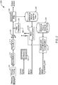
FIG. 1 , an exemplary Multi-view Video Coding (MVC) encoder to which the present principles may be applied is indicated generally by thereference numeral 100. Theencoder 100 includes acombiner 105 having an output connected in signal communication with an input of atransformer 110. An output of thetransformer 110 is connected in signal communication with an input ofquantizer 115. An output of thequantizer 115 is connected in signal communication with an input of anentropy coder 120 and an input of aninverse quantizer 125. An output of theinverse quantizer 125 is connected in signal communication with an input of aninverse transformer 130. An output of theinverse transformer 130 is connected in signal communication with a first non-inverting input of acombiner 135. An output of thecombiner 135 is connected in signal communication with an input of anintra predictor 145 and an input of adeblocking filter 150. An output of thedeblocking filter 150 is connected in signal communication with an input of a reference picture store 155 (for view i). An output of thereference picture store 155 is connected in signal communication with a first input of amotion compensator 175 and a first input of amotion estimator 180. An output of themotion estimator 180 is connected in signal communication with a second input of themotion compensator 175 - An output of a reference picture store 160 (for other views) is connected in signal communication with a first input of a disparity/
illumination estimator 170 and a first input of a disparity/illumination compensator 165. An output of the disparity/illumination estimator 170 is connected in signal communication with a second input of the disparity/illumination compensator 165. - An output of the
entropy decoder 120 is available as an output of theencoder 100. A non-inverting input of thecombiner 105 is available as an input of theencoder 100, and is connected in signal communication with a second input of the disparity/illumination estimator 170, and a second input of themotion estimator 180. An output of aswitch 185 is connected in signal communication with a second non-inverting input of thecombiner 135 and with an inverting input of thecombiner 105. Theswitch 185 includes a first input connected in signal communication with an output of themotion compensator 175, a second input connected in signal communication with an output of the disparity/illumination compensator 165, and a third input connected in signal communication with an output of theintra predictor 145. - A
mode decision module 140 has an output connected to theswitch 185 for controlling which input is selected by theswitch 185. - Turning to
FIG. 2 , an exemplary Multi-view Video Coding (MVC) decoder to which the present principles may be applied is indicated generally by thereference numeral 200. Thedecoder 200 includes an entropy decoder 205 having an output connected in signal communication with an input of aninverse quantizer 210. An output of the inverse quantizer is connected in signal communication with an input of aninverse transformer 215. An output of theinverse transformer 215 is connected in signal communication with a first non-inverting input of acombiner 220. An output of thecombiner 220 is connected in signal communication with an input of adeblocking filter 225 and an input of anintra predictor 230. An output of thedeblocking filter 225 is connected in signal communication with an input of a reference picture store 240 (for view i). An output of thereference picture store 240 is connected in signal communication with a first input of amotion compensator 235. - An output of a reference picture store 245 (for other views) is connected in signal communication with a first input of a disparity/
illumination compensator 250. - An input of the entropy coder 205 is available as an input to the
decoder 200, for receiving a residue bitstream. Moreover, an input of amode module 260 is also available as an input to thedecoder 200, for receiving control syntax to control which input is selected by the switch 255. Further, a second input of themotion compensator 235 is available as an input of thedecoder 200, for receiving motion vectors. Also, a second input of the disparity/illumination compensator 250 is available as an input to thedecoder 200, for receiving disparity vectors and illumination compensation syntax. - An output of a switch 255 is connected in signal communication with a second non-inverting input of the
combiner 220. A first input of the switch 255 is connected in signal communication with an output of the disparity/illumination compensator 250. A second input of the switch 255 is connected in signal communication with an output of themotion compensator 235. A third input of the switch 255 is connected in signal communication with an output of theintra predictor 230. An output of themode module 260 is connected in signal communication with the switch 255 for controlling which input is selected by the switch 255. An output of thedeblocking filter 225 is available as an output of thedecoder 200. - Embodiments of the present principles are directed to the efficient coding of multi-view video sequences. A multi-view video sequence is a set of two or more video sequences that capture the same scene from different view points. In particular, various embodiments in accordance with the present principles are directed to illumination compensation and/or color compensation for encoding and decoding multi-view video sequences.
- The present principles take into account that since a multi-view video source involves multiple views of the same scene, there exists a high degree of correlation between the multiple view images. Therefore, view redundancy can be exploited in addition to temporal redundancy, and is achieved by performing view prediction across the different views (cross-view prediction).
- For illustrative purposes, the description provided herein is directed to a Multi-view Video Coding extension of the International Organization for Standardization/International Electrotechnical Commission (ISO/IEC) Moving Picture Experts Group-4 (MPEG-4) Part 10 Advanced Video Coding (AVC) standard/International Telecommunication Union, Telecommunication Sector (ITU-T) H.264 recommendation (hereinafter the "MPEG-4 AVC standard"). However, it is to be appreciated that the present principles are also applicable to other video coding standards, as are readily determined by one of ordinary skill in this and related arts. That is, given the teachings of the present principles provided herein, one of ordinary skill in this and related arts will readily be able to implement the present principles with respect to various video coding standards including the MPEG-4 AVC standard and other video coding standards, while maintaining the scope of the present principles.
- In the framework of the MPEG-4 AVC standard, illumination compensation can be considered part of the disparity compensation process, where cross-view prediction (view prediction across different views of a multi-view sequence) includes an offset to address illumination differences across different camera views. Due to the strong correlation among spatially neighboring blocks, the offset can be differentially encoded before being quantized and entropy encoded. The illumination compensation may be implemented to be switchable on a block-basis since different signal blocks suffer from different levels of illumination mismatch. In addition to illumination compensation, color compensation design is also proposed to address color discrepancies among different camera views.
- In an illustrative embodiment of the present principles involving illumination compensation and color compensation, directed to the Multi-view Video Coding (MVC) extension of the MPEG-4 AVC standard, an exemplary framework is set forth as follows. At the slice level, a new syntax element (ic_prediction_flag) is introduced to indicate whether illumination compensation is enabled for the current slice. At the macroblock-level, two new syntax elements are introduced: one (ic_enable) is introduced to indicate the utilization of illumination compensation for each block; another (ic_sym) is introduced to convey the illumination offset parameter.
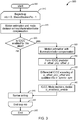
- Turning to
FIG. 3 , an exemplary video encoding method with illumination compensation for multi-view video content is indicated generally by thereference numeral 300. Themethod 300 includes astart block 305 that passes control to aloop limit block 310. Theloop limit block 310 begins a loop over each macroblock in a current slice including setting a range from the loop using a variable mb = 0 to MacroBlockInPic-1, and passes control to adecision block 315. Thedecision block 315 determines whether or not illumination compensation (IC) is enabled for the current slice. If so, the control is passed to afunction block 320. Otherwise, control is passed to afunction block 350. - The
function block 320 performs motion estimation with illumination compensation, and passes control to afunction block 325. Thefunction block 325 forms an IC predictor ic_offset_p, and passes control to afunction block 330. Thefunction block 330 performs differential illumination compensation encoding of ic_offset, quantizes ic_offset into ic_sym, and passes control to afunction block 335. Thefunction block 335 performs an illumination compensation mode decision, decides the ic_prediction_flag, and passes control to afunction block 340. Thefunction block 340 performs syntax writing, and passes control to aloop limit block 345. Theloop limit block 345 ends the loop over each macroblock in the current slice, and passes control to anend block 355. - The
function block 350 performs motion estimation and renders a motion decision without illumination compensation, and passes control to thefunction block 340. - Turning to
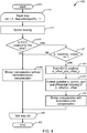
FIG. 4 , an exemplary video decoding method with illumination compensation for multi-view video content is indicated generally by thereference numeral 400. Themethod 400 includes astart block 405 that passes control to aloop limit block 410. Theloop limit block 410 begins a loop over each macroblock in a current slice including setting a range for the loop using a variable mb = 0 to MacroBlockslnPic-1, and passes control to afunction block 415. Thefunction block 415 reads syntax, and passes control to adecision block 420. Thedecision block 420 determines whether or not illumination compensation is enabled for the current slice. If so, then control is passed to adecision block 425. Otherwise, control is passed to afunction block 450. - The
decision block 425 determines whether or not ic_prediction_flag is equal to 1. If so, the control is passed to afunction block 430. Otherwise, control is passed to thefunction block 450. - The
function block 430 forms an IC predictor ic_offset_p, and passes control to afunction block 435. Thefunction block 435 inverse quantizes ic_sym, differentially decodes ic_offset, and passes control to afunction block 440. Thefunction block 440 performs motion compensation with illumination, and passes control to aloop limit block 445. Theloop limit block 445 ends the loop over each macroblock in the current slice, and passes control to anend block 455. - The
function block 450 performs motion compensation without illumination compensation, and passes control to theloop limit block 445. - A description will now be given regarding the use of illumination compensation as part of the cross-view prediction process in accordance with an exemplary embodiment of the present principles.
- Illumination compensation is done in the context of cross-view prediction for Multi-view Video Coding. In this scenario, cross-view prediction typically involves the computation of a disparity field between pictures from different views. The disparity field is in cross-view prediction what the motion field is in temporal prediction. When applied to a coding scheme, cross-view prediction is an effective tool to exploit view redundancy.
- For the sake of simplicity, it will be presumed in the following that cross-view prediction and, by extension, disparity estimation, is performed on a block basis. However, it is to be appreciated that, given the teachings of the present principles provided herein, the extension of such teachings to other groups of samples is readily determined and implemented by one of ordinary skill in this and related arts, while maintaining the scope of the present principles.
- Also, it is to be further appreciated that while some embodiments of the present principles are described herein with respect to being applied to a Multi-view Video Coding extension of the MPEG-4 AVC standard, for which motion compensation and disparity compensation are enabled, given the teachings of the present principles provided herein, implementations of the present principles may also be directed to any other Multi-view Video Coding schemes for which disparity compensation is enabled, as readily determined and implemented by one of ordinary skill in the and related arts, while maintaining the scope of the present principles.
- Moreover, it is to be appreciated that while some embodiments of the present principles directed to illumination compensation are described herein with respect to Multi-view Video Coding, given the teachings of the present principles provided herein, one of ordinary skill in this and related arts will readily contemplate other video-related scenarios to which the present principles may be applied, while maintaining the scope of the present principles. For example, the present principles may be applied, but are not limited to, image registration and camera calibration.
- A description will now be given regarding the transmission of illumination compensation syntax elements in accordance with an exemplary embodiment of the present principles.
- In exemplary embodiments of the present principles applied to a Multi-view Video Coding extension of the MPEG-4 AVC standard, a new syntax is introduced in the slice header called ic_prediction_flag, which indicates whether illumination compensation (IC) is used for that slice. If the cross-view prediction is disabled for the whole slice, then ic_prediction_flag will be equal to zero and there will be no further IC-related syntaxes in the slice.
- The degree of illumination mismatch varies from one part of the view image to another. Thus, it might not be efficient to send IC parameters for all the blocks using disparity compensation. To serve that purpose, a new block-based syntax flag called ic_enable is introduced in the macroblock/sub-macroblock level to indicate whether IC is utilized for one specific block.
- The MPEG-4 AVC standard supports variable block size motion compensation, with block sizes ranging from 16x16 to 4x4. To reduce the overhead of sending too many ic_enable flags and ic_sym, the switching of IC need not to be applied on all block sizes. In one particular embodiment, the switching of IC is only applied on blocks with a size larger than, or equal to, 8x8.
- The context adaptive binary arithmetic coding (CABAC) context design for the encoding of ic_enable is designed as followings: (1) for block sizes in {16x16, 16x8 or 8x16}, three CABAC contexts are used depending on the ic_enable flags of the upper and left macroblocks; and (2) for block size 8x8, a separate CABAC context is assigned without referring to neighboring blocks.
- For illustrative purposes, the IC-related syntax tables are shown in Table 1 to Table 3. Table 1 illustrates the slice header syntax for Multi-view Video Coding (MVC). Table 2 illustrates macroblock layer syntax. Table 3 illustrates sub-macroblock prediction syntax.


- A description will now be given regarding disparity estimation with illumination compensation in accordance with an exemplary embodiment of the present principles.
- In the particular scenario of a coding application, illumination compensation (IC) will be considered part of the disparity compensation process. More specifically, when IC is enabled in the disparity compensation of a block, the illumination compensated reference block, Br , is calculated as follows:

FIG. 5 , DV/ic_offset/ic_enable are used together in the disparity compensation process. - Turning to
FIG. 5 , an exemplary apparatus for reference block generation with illumination compensation for multi-view video content is indicated generally by thereference numeral 500. The apparatus 600 includes an illumination compensation quantizer 505 having an output connected in signal communication with a first non-inverting input of acombiner 515. An output of thecombiner 515 is connected in signal communication with a second non-inverting input of thecombiner 515 and with a first non-inverting input of acombiner 520. - An output of a reference picture store 510 (for other views) is connected in signal communication with a second non-inverting input of the
combiner 520 and with a first input of aswitch 525. - A second input of a
switch 525 is connected in signal communication with an output of thecombiner 520. - An input of the
illumination compensation quantizer 505 is available as an input to theapparatus 500, for receiving ic_sym syntax. Moreover, an input of thereference picture store 510 is available as an input of the apparatus, for receiving disparity vectors. Further, theapparatus 500 includes an input for receiving an ic_enable syntax for controlling which input is selected by theswitch 525. An output of theswitch 525 is available as an output of theapparatus 500. - At the block-level, the illumination compensation parameter, ic_offset, is obtained through differential encoding and uniform quantization.
- A description will now be given regarding differential encoding of ic_offset in accordance with an exemplary embodiment of the present principles.
- There exists strong correlation among the ic_offset's in neighboring blocks. To take advantage of this property, the ic_offset is differentiated before quantization as follows:

- The ic_offset_p is computed according to the following rules. In a first rule, the default value of ic_offset_p is 0. The default value is used when there is no neighboring block with IC available. In a second rule, ic_offset_p is set depending on the block size of the MB on the left, as follows: (1) if the block size = 16x16, then the ic_offset of the left block is used; (2) if the block size = 16x8 or 8x16, then the ic_offset of the second block is used; and (3) if the block size = 8x8 or less, then the available ic_offset of
8x8 block index 3, 1, 2, 0 (in this order) is used. In a third rule, if there is no neighboring macroblock on the left, then ic_offset from the upper block is used instead. - A description will now be given regarding the quantization of ic_sym in accordance with an exemplary embodiment of the present principles.
- Uniform quantization is applied to the differentiated ic_offset:

- If a fixed step-size quantization method is used, there is no need for extra syntax to signal µ. In the case when a fixed step-size quantization is not utilized, the transmission of syntax should be considered.
- A description will now be given regarding entropy coding of ic_sym in accordance with an exemplary embodiment of the present principles.
- For ic_sym, unary binarization is used in CABAC. For example, if |ic_sym| is 1, then it is binarized as "10", and if ic_sym is 3, then it is binarized as "1110". Since ic_sym is differentially encoded, a value of ic_sym close to 0 is more likely to occur. To exploit this property, four different contexts are assigned to each binarized symbol. After binarization, one symbol bit may be added in the end, which is encoded with no context.
- A description will now be given regarding color compensation in accordance with an exemplary embodiment of the present principles.
- Poor camera calibration can also cause color mismatches in addition to the illumination mismatch. Some embodiments of the present principles address this problem by extending the illumination compensation (IC) approach previously described to color compensation (CC). For simplicity sake, it will be presumed that color compensation is applied to the UV color components of the YUV color space. However, it is to be appreciated that, given the teachings of the present principles provided herein, one of ordinary skill in this and related arts will contemplate and readily implement the present principles with respect to other color spaces, while maintaining the scope of the present principles.
- Two exemplary methods will now be described with respect to color compensation in accordance with the present principles. The first is a local color compensation method and the second is a global color compensation method. Of course, given the teachings of the present principles provided herein, variations and extensions of the two approaches described herein are readily contemplated by one of ordinary skill in this and related arts, while maintaining the scope of the present invention.
- In the local color compensation method, similar to illumination compensation (IC), a local color compensation parameter cc_offset is introduced. These two different cc_offset's for the U and V channels share the same flag ic_enable and the same disparity vector.
- For the YUV420 chrominance sampling format, the width and height of the chrominance block is half of the luminance block. To avoid spending too many bits on the color compensation syntaxes, the block size for color compensation is fixed to be 8x8. The cc_enable flag can either be signaled independent of ic_enable, or can be derived from ic_enable.
- With respect to the global color compensation method, generally chrominance channels are much smoother than the luminance channel. A more economical method for color compensation is to use a global compensation parameter: cc_offset_global. Global cc_offset can be calculated in the slice or frame level and be applied to every block in the same slice or frame.
- A description will now be given of some of the many attendant advantages/features of the present invention, some of which have been mentioned above. For example, one advantage/feature is a video encoder that includes an encoder for encoding a picture by enabling color compensation of at least one color component in a prediction of the picture based upon a correlation factor relating to color data between the picture and another picture. The picture and the other picture have different view points and both corresponding to multi-view content for a same or similar scene.
- Another advantage/feature is the video encoder as described above, wherein the encoder encodes the picture to provide a resultant bitstream compliant with at least one of the International Organization for Standardization/International Electrotechnical Commission Moving Picture Experts Group-4 Part 10 Advanced Video Coding standard/International Telecommunication Union, Telecommunication Sector H.264 recommendation and an extension thereto.
- Yet another advantage/feature is the video encoder as described above, wherein the encoder uses a high-level syntax to enable the color compensation.
- Moreover, another advantage/feature is the video encoder that uses a high-level syntax as described above, wherein the high-level syntax includes a slice-level syntax.
- Further, another advantage/feature is the video encoder as described above, wherein the encoder uses a block-level syntax to indicate whether the color compensation is used in the prediction for the picture.
- Also, another advantage/feature is the video encoder that uses a block-level syntax as described above, wherein the encoder uses context adaptive binary arithmetic coding contexts for coding the block-level syntax, the context adaptive binary arithmetic coding contexts selected based on block size.
- Additionally, another advantage/feature is the video encoder as described above, wherein the encoder uses a block-level syntax to signal color compensation information.
- Moreover, another advantage/feature is the video encoder that uses the block-level syntax as described above, wherein the encoder uses context adaptive binary arithmetic coding contexts for coding the block-level syntax, the context adaptive binary arithmetic coding contexts selected based on block size.
- Also, another advantage/feature is the video encoder that uses the block-level syntax as described above, wherein the color compensation information includes a color offset parameter.
- Additionally, another advantage/feature is the video encoder as described above, wherein the encoder uses a slice-level syntax to signal an amount of color compensation applied on chrominance channels of an entire slice corresponding to the picture.
- Moreover, another advantage/feature is the video encoder as described above, wherein the encoder encodes the picture by also enabling illumination compensation in the prediction of the picture based upon a correlation factor relating to illumination data between the picture and the other picture.
- Further, another advantage/feature is the video encoder that encodes the picture by also enabling illumination compensation as described above, wherein the encoder uses a slice-level syntax to enable the illumination compensation.
- Also, another advantage/feature is the video encoder that encodes the picture by also enabling illumination compensation as described above, wherein the encoder uses a block-level syntax to indicate whether the illumination compensation is used in the prediction for the picture.
- Additionally, another advantage/feature is the video encoder that encodes the picture by also enabling illumination compensation as described above, wherein different block-level syntaxes are used to indicate the illumination compensation and the color compensation, respectively, and the different block-level syntaxes are signaled independently.
- Moreover, another advantage/feature is the video encoder that encodes the picture by also enabling illumination compensation as described above, wherein different block-level syntaxes are used to indicate the illumination compensation and the color compensation, respectively, and one of the different block-level syntaxes is derived from another one of the different block-level syntaxes.
- Further, another advantage/feature is the video encoder that encodes the picture by also enabling illumination compensation as described above, wherein the encoder uses a block-level syntax to signal illumination compensation information.
- Further, another advantage/feature is the video encoder that encodes the picture by also enabling illumination compensation and that uses a block-level syntax as described above, wherein the encoder uses context adaptive binary arithmetic coding contexts for coding the block-level syntax, the context adaptive binary arithmetic coding contexts selected based on block size.
- Also, another advantage/feature is the video encoder that encodes the picture by also enabling illumination compensation and that uses a block-level syntax as described above, wherein the illumination compensation information includes an illumination offset parameter.
- Additionally, another advantage/feature is the video encoder that encodes the picture by also enabling illumination compensation as described above, wherein the encoder uses differential encoding of at least one of illumination compensation parameters and color compensation parameters on a block-level.
- Moreover, another advantage/feature is the video encoder that encodes the picture by also enabling illumination compensation and that also uses differential encoding as described above, wherein the encoder applies uniform quantization on at least one of the differential encoded illumination compensation parameters and the differential encoded color compensation parameters.
- These and other features and advantages of the present invention may be readily ascertained by one of ordinary skill in the pertinent art based on the teachings herein. It is to be understood that the teachings of the present invention may be implemented in various forms of hardware, software, firmware, special purpose processors, or combinations thereof.
- Most preferably, the teachings of the present invention are implemented as a combination of hardware and software. Moreover, the software may be implemented as an application program tangibly embodied on a program storage unit. The application program may be uploaded to, and executed by, a machine comprising any suitable architecture. Preferably, the machine is implemented on a computer platform having hardware such as one or more central processing units ("CPU"), a random access memory ("RAM"), and input/output ("I/O") interfaces. The computer platform may also include an operating system and microinstruction code. The various processes and functions described herein may be either part of the microinstruction code or part of the application program, or any combination thereof, which may be executed by a CPU. In addition, various other peripheral units may be connected to the computer platform such as an additional data storage unit and a printing unit.
- It is to be further understood that, because some of the constituent system components and methods depicted in the accompanying drawings are preferably implemented in software, the actual connections between the system components or the process function blocks may differ depending upon the manner in which the present invention is programmed. Given the teachings herein, one of ordinary skill in the pertinent art will be able to contemplate these and similar implementations or configurations of the present invention.
- Although the illustrative embodiments have been described herein with reference to the accompanying drawings, it is to be understood that the present invention is not limited to those precise embodiments, and that various changes and modifications are intended to be included within the scope of the present invention as set forth in the appended claims.
Claims (9)
- An apparatus, comprising:
a video decoder for decoding a picture by selectively enabling color compensation using a block level syntax element on a block basis, of two color components in a prediction of the picture, also having one luminance component, using an offset relating to color data between the two color components of the picture and the corresponding components of another picture, wherein each color component uses a separate offset for compensation, and the luminance component has one luminance offset, the picture and the other picture having different viewpoints and both corresponding to multi-view content for a same or similar scene, and wherein there is one illumination compensation enable flag and one color compensation enable flag, wherein the offset is differentially coded with respect to offsets from spatially neighboring blocks. - The apparatus of claim 1, wherein said decoder (200) decodes the picture from a resultant bitstream compliant with at least one of the International Organization for Standardization/International Electrotechnical Commission Moving Picture Experts Group-4 Part 10 Advanced Video Coding standard/International Telecommunication Union, Telecommunication Sector H.264 recommendation and an extension thereto.
- The apparatus of claim 1, wherein said decoder (200) uses the block-level syntax to determine, whether the color compensation is used in the prediction for the picture.
- The apparatus of claim 3, wherein said decoder (200) uses context adaptive binary arithmetic coding contexts for decoding the block-level syntax, the context adaptive binary arithmetic coding contexts selected based on block size.
- The apparatus of claim 1, wherein said decoder (200) reads a block-level syntax to signal color compensation information.
- The apparatus of claim 5, wherein said decoder (200) uses context adaptive binary arithmetic coding contexts for decoding the block-level syntax, the context adaptive binary arithmetic coding contexts selected based on block size.
- The apparatus of claim 1, wherein a slice-level syntax is used to enable the color compensation (320).
- The apparatus of claim 1, wherein a slice-level syntax is used to signal or determine an amount of color compensation applied on chrominance channels of an entire slice corresponding to the picture (345).
- The apparatus of claim 1, wherein the picture is decoded by also enabling illumination compensation in the prediction of the picture based upon a correlation factor relating to illumination data between the picture and the other picture (300).
Applications Claiming Priority (4)
| Application Number | Priority Date | Filing Date | Title |
|---|---|---|---|
| US75737206P | 2006-01-09 | 2006-01-09 | |
| US75728906P | 2006-01-09 | 2006-01-09 | |
| EP07716252.7A EP1972147B8 (en) | 2006-01-09 | 2007-01-04 | Methods and Apparatus for Illumination and Color Compensation for Multiview Video Coding |
| PCT/US2007/000091 WO2007081713A1 (en) | 2006-01-09 | 2007-01-04 | Method and apparatus for providing reduced resolution update mode for multi-view video coding |
Related Parent Applications (3)
| Application Number | Title | Priority Date | Filing Date |
|---|---|---|---|
| EP07716252.7 Division | 2007-01-04 | ||
| EP07716252.7A Division-Into EP1972147B8 (en) | 2006-01-09 | 2007-01-04 | Methods and Apparatus for Illumination and Color Compensation for Multiview Video Coding |
| EP07716252.7A Division EP1972147B8 (en) | 2006-01-09 | 2007-01-04 | Methods and Apparatus for Illumination and Color Compensation for Multiview Video Coding |
Publications (2)
| Publication Number | Publication Date |
|---|---|
| EP2424244A1 EP2424244A1 (en) | 2012-02-29 |
| EP2424244B1 true EP2424244B1 (en) | 2019-09-11 |
Family
ID=38121957
Family Applications (3)
| Application Number | Title | Priority Date | Filing Date |
|---|---|---|---|
| EP11190379.5A Active EP2424244B1 (en) | 2006-01-09 | 2007-01-04 | Apparatus for illumination and color compensation for multi-view video decoding |
| EP07716252.7A Active EP1972147B8 (en) | 2006-01-09 | 2007-01-04 | Methods and Apparatus for Illumination and Color Compensation for Multiview Video Coding |
| EP11190381.1A Active EP2424245B1 (en) | 2006-01-09 | 2007-01-04 | Methods and apparatus for illumination and color compensation for multi-view video coding |
Family Applications After (2)
| Application Number | Title | Priority Date | Filing Date |
|---|---|---|---|
| EP07716252.7A Active EP1972147B8 (en) | 2006-01-09 | 2007-01-04 | Methods and Apparatus for Illumination and Color Compensation for Multiview Video Coding |
| EP11190381.1A Active EP2424245B1 (en) | 2006-01-09 | 2007-01-04 | Methods and apparatus for illumination and color compensation for multi-view video coding |
Country Status (11)
| Country | Link |
|---|---|
| US (4) | US8902977B2 (en) |
| EP (3) | EP2424244B1 (en) |
| JP (6) | JP5224458B2 (en) |
| KR (1) | KR101357982B1 (en) |
| CN (2) | CN104270639B (en) |
| AU (1) | AU2007205227B2 (en) |
| BR (1) | BRPI0706352B1 (en) |
| ES (1) | ES2625902T3 (en) |
| HK (1) | HK1203728A1 (en) |
| RU (1) | RU2457632C2 (en) |
| WO (1) | WO2007081713A1 (en) |
Families Citing this family (39)
| Publication number | Priority date | Publication date | Assignee | Title |
|---|---|---|---|---|
| KR101357982B1 (en) * | 2006-01-09 | 2014-02-05 | 톰슨 라이센싱 | Method and apparatus for providing reduced resolution update mode for multi-view video coding |
| KR100959538B1 (en) | 2006-03-30 | 2010-05-27 | 엘지전자 주식회사 | A method and apparatus for decoding/encoding a video signal |
| US20100091845A1 (en) * | 2006-03-30 | 2010-04-15 | Byeong Moon Jeon | Method and apparatus for decoding/encoding a video signal |
| US8532178B2 (en) * | 2006-08-25 | 2013-09-10 | Lg Electronics Inc. | Method and apparatus for decoding/encoding a video signal with inter-view reference picture list construction |
| US20080050608A1 (en) * | 2006-08-25 | 2008-02-28 | Mcfaul Surry D | Metal coating process and product |
| KR101370287B1 (en) * | 2006-11-22 | 2014-03-07 | 세종대학교산학협력단 | Method and apparatus for deblocking filtering |
| KR20090035427A (en) * | 2007-10-05 | 2009-04-09 | 한국전자통신연구원 | Encoding and decoding method for single-view video or multi-view video and apparatus thereof |
| KR101700966B1 (en) | 2008-01-10 | 2017-01-31 | 톰슨 라이센싱 | Methods and apparatus for illumination compensation of intra-predicted video |
| US8311111B2 (en) * | 2008-09-11 | 2012-11-13 | Google Inc. | System and method for decoding using parallel processing |
| JP5267886B2 (en) * | 2009-04-08 | 2013-08-21 | ソニー株式会社 | REPRODUCTION DEVICE, RECORDING MEDIUM, AND INFORMATION PROCESSING METHOD |
| EP2517181A1 (en) | 2009-12-21 | 2012-10-31 | Thomson Licensing | Method for generating an environment map |
| EP2529551B1 (en) * | 2010-01-27 | 2022-03-16 | Dolby Laboratories Licensing Corporation | Methods and systems for reference processing in image and video codecs |
| PT3244612T (en) * | 2010-04-13 | 2018-11-14 | Ge Video Compression Llc | Coding of significance maps and transform coefficient blocks |
| US8660174B2 (en) * | 2010-06-15 | 2014-02-25 | Mediatek Inc. | Apparatus and method of adaptive offset for video coding |
| US9055305B2 (en) | 2011-01-09 | 2015-06-09 | Mediatek Inc. | Apparatus and method of sample adaptive offset for video coding |
| US9161041B2 (en) * | 2011-01-09 | 2015-10-13 | Mediatek Inc. | Apparatus and method of efficient sample adaptive offset |
| US20120294353A1 (en) * | 2011-05-16 | 2012-11-22 | Mediatek Inc. | Apparatus and Method of Sample Adaptive Offset for Luma and Chroma Components |
| MX352866B (en) * | 2011-06-28 | 2017-12-13 | Nec Corp | Method for coding video quantization parameter and method for decoding video quantization parameter. |
| EP2749024A1 (en) * | 2011-08-25 | 2014-07-02 | Telefonaktiebolaget L M Ericsson (publ) | Depth map encoding and decoding |
| EP2805511B1 (en) | 2012-01-20 | 2019-03-06 | Sun Patent Trust | Methods and apparatus for encoding and decoding video using temporal motion vector prediction |
| EP2811743B1 (en) | 2012-02-03 | 2021-03-03 | Sun Patent Trust | Image encoding method, image decoding method, image encoding device, image decoding device, and image encoding/decoding device |
| JP6421931B2 (en) | 2012-03-06 | 2018-11-14 | サン パテント トラスト | Moving picture coding method and moving picture coding apparatus |
| JP6681609B2 (en) | 2012-04-09 | 2020-04-15 | サン パテント トラスト | Image coding method and image decoding method |
| WO2013168407A1 (en) | 2012-05-09 | 2013-11-14 | Panasonic Corporation | Method of performing motion vector prediction, encoding and decoding methods, and apparatuses thereof |
| RU2510944C2 (en) * | 2012-07-03 | 2014-04-10 | Корпорация "САМСУНГ ЭЛЕКТРОНИКС Ко., Лтд." | Method of encoding/decoding multi-view video sequence based on adaptive local adjustment of brightness of key frames without transmitting additional parameters (versions) |
| KR102105323B1 (en) * | 2013-04-15 | 2020-04-28 | 인텔렉추얼디스커버리 주식회사 | A method for adaptive illuminance compensation based on object and an apparatus using it |
| CN105393534A (en) * | 2013-06-18 | 2016-03-09 | 夏普株式会社 | Illumination compensation device, lm predict device, image decoding device, image coding device |
| US9860529B2 (en) * | 2013-07-16 | 2018-01-02 | Qualcomm Incorporated | Processing illumination compensation for video coding |
| US10284876B2 (en) | 2013-07-18 | 2019-05-07 | Samsung Electronics Co., Ltd | Intra scene prediction method of depth image for interlayer video decoding and encoding apparatus and method |
| US9294766B2 (en) * | 2013-09-09 | 2016-03-22 | Apple Inc. | Chroma quantization in video coding |
| WO2015056955A1 (en) | 2013-10-14 | 2015-04-23 | 삼성전자 주식회사 | Method and apparatus for coding multi-view video, and method and apparatus for decoding multi-view vide |
| JP2017523682A (en) | 2014-06-20 | 2017-08-17 | サムスン エレクトロニクス カンパニー リミテッド | Depth video prediction mode transmission method and apparatus for inter-layer video encoding / decoding |
| JP2016127372A (en) * | 2014-12-26 | 2016-07-11 | Kddi株式会社 | Video encoder, video decoder, video processing system, video encoding method, video decoding method, and program |
| US20180091812A1 (en) * | 2016-09-23 | 2018-03-29 | Apple Inc. | Video compression system providing selection of deblocking filters parameters based on bit-depth of video data |
| US10715810B2 (en) * | 2018-02-20 | 2020-07-14 | Qualcomm Incorporated | Simplified local illumination compensation |
| US10834409B2 (en) * | 2018-04-06 | 2020-11-10 | Arris Enterprises Llc | System and method of implementing multiple prediction models for local illumination compensation |
| US11750811B2 (en) * | 2018-04-06 | 2023-09-05 | Comcast Cable Communications, Llc | Systems, methods, and apparatuses for processing video |
| US11272200B2 (en) * | 2019-06-24 | 2022-03-08 | Tencent America LLC | Method and apparatus for video coding |
| US20230086521A1 (en) * | 2021-09-20 | 2023-03-23 | Tencent America LLC | Feature compression for video coding for machines |
Family Cites Families (31)
| Publication number | Priority date | Publication date | Assignee | Title |
|---|---|---|---|---|
| JP3150446B2 (en) | 1992-09-29 | 2001-03-26 | 富士通株式会社 | Image efficient coding method |
| JPH0749944A (en) | 1993-08-04 | 1995-02-21 | Canon Inc | Method and device for image processing |
| DE69434685T2 (en) | 1993-08-04 | 2006-09-14 | Canon K.K. | Image processing method and apparatus |
| DE4331376C1 (en) | 1993-09-15 | 1994-11-10 | Fraunhofer Ges Forschung | Method for determining the type of encoding to selected for the encoding of at least two signals |
| JPH08331607A (en) * | 1995-03-29 | 1996-12-13 | Sanyo Electric Co Ltd | Three-dimensional display image generating method |
| KR100414629B1 (en) * | 1995-03-29 | 2004-05-03 | 산요덴키가부시키가이샤 | 3D display image generation method, image processing method using depth information, depth information generation method |
| US6111596A (en) * | 1995-12-29 | 2000-08-29 | Lucent Technologies Inc. | Gain and offset correction for efficient stereoscopic coding and improved display |
| JPH10155104A (en) * | 1996-11-22 | 1998-06-09 | Canon Inc | Compound eye image pickup method and device and storage medium |
| EP0830034B1 (en) * | 1996-09-11 | 2005-05-11 | Canon Kabushiki Kaisha | Image processing for three dimensional display of image data on the display of an image sensing apparatus |
| US6057884A (en) * | 1997-06-05 | 2000-05-02 | General Instrument Corporation | Temporal and spatial scaleable coding for video object planes |
| US6043838A (en) * | 1997-11-07 | 2000-03-28 | General Instrument Corporation | View offset estimation for stereoscopic video coding |
| US6055274A (en) * | 1997-12-30 | 2000-04-25 | Intel Corporation | Method and apparatus for compressing multi-view video |
| JPH11252585A (en) | 1998-03-05 | 1999-09-17 | Nippon Hoso Kyokai <Nhk> | Parallax amount estimate device |
| US6470048B1 (en) * | 1999-07-12 | 2002-10-22 | Pixelon.Com, Inc. | Frequency-based video data substitution for increased video compression ratios |
| TW544671B (en) | 2000-02-25 | 2003-08-01 | Sony Corp | Recording medium, recording apparatus, and reading apparatus |
| JP2001333350A (en) * | 2000-03-15 | 2001-11-30 | Sony Corp | Method and device for adjusting picture quality |
| KR100450823B1 (en) | 2001-11-27 | 2004-10-01 | 삼성전자주식회사 | Node structure for representing 3-dimensional objects using depth image |
| RU2237283C2 (en) * | 2001-11-27 | 2004-09-27 | Самсунг Электроникс Ко., Лтд. | Device and method for presenting three-dimensional object on basis of images having depth |
| JP4015934B2 (en) | 2002-04-18 | 2007-11-28 | 株式会社東芝 | Video coding method and apparatus |
| KR100481732B1 (en) * | 2002-04-20 | 2005-04-11 | 전자부품연구원 | Apparatus for encoding of multi view moving picture |
| KR100751422B1 (en) * | 2002-12-27 | 2007-08-23 | 한국전자통신연구원 | A Method of Coding and Decoding Stereoscopic Video and A Apparatus for Coding and Decoding the Same |
| US7778328B2 (en) | 2003-08-07 | 2010-08-17 | Sony Corporation | Semantics-based motion estimation for multi-view video coding |
| JP2005141527A (en) * | 2003-11-07 | 2005-06-02 | Sony Corp | Image processing apparatus, image processing method and computer program |
| US7379608B2 (en) * | 2003-12-04 | 2008-05-27 | Fraunhofer-Gesellschaft Zur Foerderung Der Angewandten Forschung, E.V. | Arithmetic coding for transforming video and picture data units |
| JP2007528675A (en) | 2004-03-09 | 2007-10-11 | トムソン リサーチ ファンディング コーポレイション | Reduced resolution update mode for AVC |
| US7561620B2 (en) * | 2004-08-03 | 2009-07-14 | Microsoft Corporation | System and process for compressing and decompressing multiple, layered, video streams employing spatial and temporal encoding |
| JP4440067B2 (en) * | 2004-10-15 | 2010-03-24 | キヤノン株式会社 | Image processing program for stereoscopic display, image processing apparatus, and stereoscopic display system |
| CN102263962A (en) * | 2004-12-10 | 2011-11-30 | 韩国电子通信研究院 | Apparatus for universal coding for multi-view video |
| WO2006124885A2 (en) * | 2005-05-12 | 2006-11-23 | Kylintv, Inc. | Codec for iptv |
| KR101357982B1 (en) * | 2006-01-09 | 2014-02-05 | 톰슨 라이센싱 | Method and apparatus for providing reduced resolution update mode for multi-view video coding |
| JP6113335B1 (en) | 2016-06-03 | 2017-04-12 | グリーン アイデア テック インク.Green Idea Tech Inc. | Thermal breakage fixing member assembly shared by multiple electrical outlets |
-
2007
- 2007-01-04 KR KR1020087016119A patent/KR101357982B1/en active IP Right Grant
- 2007-01-04 EP EP11190379.5A patent/EP2424244B1/en active Active
- 2007-01-04 JP JP2008549545A patent/JP5224458B2/en active Active
- 2007-01-04 CN CN201410575263.5A patent/CN104270639B/en active Active
- 2007-01-04 BR BRPI0706352-0A patent/BRPI0706352B1/en active IP Right Grant
- 2007-01-04 AU AU2007205227A patent/AU2007205227B2/en active Active
- 2007-01-04 RU RU2008132852/07A patent/RU2457632C2/en active
- 2007-01-04 ES ES07716252.7T patent/ES2625902T3/en active Active
- 2007-01-04 CN CN200780002059.2A patent/CN101366284B/en active Active
- 2007-01-04 US US12/087,197 patent/US8902977B2/en active Active
- 2007-01-04 EP EP07716252.7A patent/EP1972147B8/en active Active
- 2007-01-04 WO PCT/US2007/000091 patent/WO2007081713A1/en active Application Filing
- 2007-01-04 EP EP11190381.1A patent/EP2424245B1/en active Active
-
2012
- 2012-05-22 JP JP2012116127A patent/JP5346108B2/en active Active
- 2012-12-21 JP JP2012278830A patent/JP5224488B2/en active Active
- 2012-12-21 JP JP2012278831A patent/JP5594913B2/en active Active
-
2013
- 2013-04-30 US US13/873,789 patent/US9241168B2/en active Active
- 2013-04-30 US US13/873,842 patent/US9237353B2/en active Active
-
2014
- 2014-07-08 JP JP2014140143A patent/JP5896490B2/en active Active
-
2015
- 2015-04-30 HK HK15104191.2A patent/HK1203728A1/en unknown
- 2015-12-10 US US14/964,750 patent/US9838694B2/en active Active
-
2016
- 2016-02-02 JP JP2016017659A patent/JP6112523B2/en active Active
Non-Patent Citations (2)
| Title |
|---|
| "Survey of Algorithms used for Multi-view Video Coding (MVC)", 71. MPEG MEETING;17-01-2005 - 21-01-2005; HONG KONG; (MOTION PICTUREEXPERT GROUP OR ISO/IEC JTC1/SC29/WG11),, no. N6909, 21 January 2005 (2005-01-21), XP030013629, ISSN: 0000-0349 * |
| ULRICH FECKER ET AL: "Luminance and Chrominance Compensation for Multi-View Sequences Using Histogram Matching", 74. MPEG MEETING; 17-10-2005 - 21-10-2005; NICE; (MOTION PICTUREEXPERT GROUP OR ISO/IEC JTC1/SC29/WG11),, no. M12487, 30 September 2005 (2005-09-30), XP030041157, ISSN: 0000-0243 * |
Also Published As
Similar Documents
| Publication | Publication Date | Title |
|---|---|---|
| EP2424244B1 (en) | Apparatus for illumination and color compensation for multi-view video decoding | |
| EP2084912B1 (en) | Methods, apparatus and storage media for local illumination and color compensation without explicit signaling | |
| US8270472B2 (en) | Methods and apparatus for adaptive reference filtering (ARF) of bi-predictive pictures in multi-view coded video | |
| US9008174B2 (en) | Methods and apparatus for illumination compensation of intra-predicted video | |
| US8953679B2 (en) | Methods and apparatus for implicit block segmentation in video encoding and decoding | |
| EP2116061A2 (en) | Methods and apparatus for reducing coding artifacts for illumination compensation and/or color compensation in multi-view coded video |
Legal Events
| Date | Code | Title | Description |
|---|---|---|---|
| AC | Divisional application: reference to earlier application |
Ref document number: 1972147 Country of ref document: EP Kind code of ref document: P |
|
| AK | Designated contracting states |
Kind code of ref document: A1 Designated state(s): DE ES FR GB IT |
|
| PUAI | Public reference made under article 153(3) epc to a published international application that has entered the european phase |
Free format text: ORIGINAL CODE: 0009012 |
|
| 17P | Request for examination filed |
Effective date: 20120827 |
|
| 17Q | First examination report despatched |
Effective date: 20160225 |
|
| RAP1 | Party data changed (applicant data changed or rights of an application transferred) |
Owner name: DOLBY INTERNATIONAL AB |
|
| STAA | Information on the status of an ep patent application or granted ep patent |
Free format text: STATUS: EXAMINATION IS IN PROGRESS |
|
| REG | Reference to a national code |
Ref country code: DE Ref legal event code: R079 Ref document number: 602007059210 Country of ref document: DE Free format text: PREVIOUS MAIN CLASS: H04N0007260000 Ipc: H04N0019597000 |
|
| GRAP | Despatch of communication of intention to grant a patent |
Free format text: ORIGINAL CODE: EPIDOSNIGR1 |
|
| STAA | Information on the status of an ep patent application or granted ep patent |
Free format text: STATUS: GRANT OF PATENT IS INTENDED |
|
| RIC1 | Information provided on ipc code assigned before grant |
Ipc: H04N 19/174 20140101ALI20190429BHEP Ipc: H04N 19/176 20140101ALI20190429BHEP Ipc: H04N 19/597 20140101AFI20190429BHEP Ipc: H04N 19/70 20140101ALI20190429BHEP Ipc: H04N 19/186 20140101ALI20190429BHEP Ipc: H04N 19/109 20140101ALI20190429BHEP Ipc: H04N 19/46 20140101ALI20190429BHEP |
|
| INTG | Intention to grant announced |
Effective date: 20190605 |
|
| GRAS | Grant fee paid |
Free format text: ORIGINAL CODE: EPIDOSNIGR3 |
|
| GRAA | (expected) grant |
Free format text: ORIGINAL CODE: 0009210 |
|
| STAA | Information on the status of an ep patent application or granted ep patent |
Free format text: STATUS: THE PATENT HAS BEEN GRANTED |
|
| AC | Divisional application: reference to earlier application |
Ref document number: 1972147 Country of ref document: EP Kind code of ref document: P |
|
| AK | Designated contracting states |
Kind code of ref document: B1 Designated state(s): DE ES FR GB IT |
|
| REG | Reference to a national code |
Ref country code: GB Ref legal event code: FG4D |
|
| REG | Reference to a national code |
Ref country code: DE Ref legal event code: R096 Ref document number: 602007059210 Country of ref document: DE |
|
| PG25 | Lapsed in a contracting state [announced via postgrant information from national office to epo] |
Ref country code: ES Free format text: LAPSE BECAUSE OF FAILURE TO SUBMIT A TRANSLATION OF THE DESCRIPTION OR TO PAY THE FEE WITHIN THE PRESCRIBED TIME-LIMIT Effective date: 20190911 |
|
| PG25 | Lapsed in a contracting state [announced via postgrant information from national office to epo] |
Ref country code: IT Free format text: LAPSE BECAUSE OF FAILURE TO SUBMIT A TRANSLATION OF THE DESCRIPTION OR TO PAY THE FEE WITHIN THE PRESCRIBED TIME-LIMIT Effective date: 20190911 |
|
| REG | Reference to a national code |
Ref country code: DE Ref legal event code: R097 Ref document number: 602007059210 Country of ref document: DE |
|
| PLBE | No opposition filed within time limit |
Free format text: ORIGINAL CODE: 0009261 |
|
| STAA | Information on the status of an ep patent application or granted ep patent |
Free format text: STATUS: NO OPPOSITION FILED WITHIN TIME LIMIT |
|
| 26N | No opposition filed |
Effective date: 20200615 |
|
| REG | Reference to a national code |
Ref country code: DE Ref legal event code: R081 Ref document number: 602007059210 Country of ref document: DE Owner name: DOLBY INTERNATIONAL AB, IE Free format text: FORMER OWNER: DOLBY INTERNATIONAL AB, AMSTERDAM ZUIDOOST, NL Ref country code: DE Ref legal event code: R081 Ref document number: 602007059210 Country of ref document: DE Owner name: DOLBY INTERNATIONAL AB, NL Free format text: FORMER OWNER: DOLBY INTERNATIONAL AB, AMSTERDAM ZUIDOOST, NL |
|
| REG | Reference to a national code |
Ref country code: FR Ref legal event code: PLFP Year of fee payment: 17 |
|
| REG | Reference to a national code |
Ref country code: DE Ref legal event code: R081 Ref document number: 602007059210 Country of ref document: DE Owner name: DOLBY INTERNATIONAL AB, IE Free format text: FORMER OWNER: DOLBY INTERNATIONAL AB, DP AMSTERDAM, NL |
|
| P01 | Opt-out of the competence of the unified patent court (upc) registered |
Effective date: 20230512 |
|
| PGFP | Annual fee paid to national office [announced via postgrant information from national office to epo] |
Ref country code: GB Payment date: 20231219 Year of fee payment: 18 |
|
| PGFP | Annual fee paid to national office [announced via postgrant information from national office to epo] |
Ref country code: FR Payment date: 20231219 Year of fee payment: 18 |
|
| PGFP | Annual fee paid to national office [announced via postgrant information from national office to epo] |
Ref country code: DE Payment date: 20231219 Year of fee payment: 18 |