EP2423556A2 - Apparatus for mounting pipe sensors - Google Patents
Apparatus for mounting pipe sensors Download PDFInfo
- Publication number
- EP2423556A2 EP2423556A2 EP11178552A EP11178552A EP2423556A2 EP 2423556 A2 EP2423556 A2 EP 2423556A2 EP 11178552 A EP11178552 A EP 11178552A EP 11178552 A EP11178552 A EP 11178552A EP 2423556 A2 EP2423556 A2 EP 2423556A2
- Authority
- EP
- European Patent Office
- Prior art keywords
- sensor
- pipe
- insert
- pipe wall
- passage
- Prior art date
- Legal status (The legal status is an assumption and is not a legal conclusion. Google has not performed a legal analysis and makes no representation as to the accuracy of the status listed.)
- Granted
Links
Images

Classifications
-
- F—MECHANICAL ENGINEERING; LIGHTING; HEATING; WEAPONS; BLASTING
- F16—ENGINEERING ELEMENTS AND UNITS; GENERAL MEASURES FOR PRODUCING AND MAINTAINING EFFECTIVE FUNCTIONING OF MACHINES OR INSTALLATIONS; THERMAL INSULATION IN GENERAL
- F16L—PIPES; JOINTS OR FITTINGS FOR PIPES; SUPPORTS FOR PIPES, CABLES OR PROTECTIVE TUBING; MEANS FOR THERMAL INSULATION IN GENERAL
- F16L41/00—Branching pipes; Joining pipes to walls
- F16L41/008—Branching pipes; Joining pipes to walls for connecting a measuring instrument
-
- G—PHYSICS
- G01—MEASURING; TESTING
- G01L—MEASURING FORCE, STRESS, TORQUE, WORK, MECHANICAL POWER, MECHANICAL EFFICIENCY, OR FLUID PRESSURE
- G01L19/00—Details of, or accessories for, apparatus for measuring steady or quasi-steady pressure of a fluent medium insofar as such details or accessories are not special to particular types of pressure gauges
- G01L19/0007—Fluidic connecting means
Definitions
- the collar 38 can also be approximately flush with the outer surface 19 of the pipe wall 12, recessed into the pipe wall 12 (e.g. toward the center axis of the pipe 10), or extended out of the pipe wall 12 (radially outward from the center axis of the pipe 10).
- Welding can include but is not limited to electron beam welding and laser welding.
- the total pipe area required to install a sensor in this fashion can be only slightly larger than the sensor 30 (e.g. 0.5 inches (12.7 mm) larger). Resultantly, less material is used and more room around the pipe 10 is available to install other sensors 30, if desirable.
- Sensors 30 can be positioned at multiple points circumferentially around the pipe 10, or in multiple points along the longitude of the pipe 10, to map pipe, fluid, and/or flow characteristics three dimensionally.
Landscapes
- Engineering & Computer Science (AREA)
- General Engineering & Computer Science (AREA)
- Physics & Mathematics (AREA)
- General Physics & Mathematics (AREA)
- Mechanical Engineering (AREA)
- Measuring Fluid Pressure (AREA)
- Investigating Or Analyzing Materials By The Use Of Magnetic Means (AREA)
Abstract
Description
- The subject matter disclosed herein relates to pipe sensors, and particularly to pipe-mounted sensors for detecting characteristics internal to the pipe.
- Sensors can be used in determining characteristics inside pipes and piping systems, such as pressure, flow volume, flow rate, temperature, moisture and humidity, and fluid concentration, amongst others. The sensors can be integral in providing measurement and control of fluids in the pipes, and in maintaining efficient and accurate operations. Efficient control and operation in commercial industries can be essential in maintaining human safety, environmental safety, and cost efficiency.
- In industries such as the oil industry, the sensors are mounted to the pipes using industry standard pipe connections, which are often large flanges on the end of a length of pipe. These flanges are bolted or screwed together at a union or joint. A sensor is attached to the flange, and the flange is connected to another flange at the end of a jointed pipe, so that the sensor is exposed to the internal area of the pipe. Because the pipe connections used for connecting sensors are also used for connecting other standard pipe equipment (e.g. pipes), the pipe connections (e.g. flanges) are very large relative to the sensors. These pipe connections can be particularly large, or otherwise onerous, in some industries, such as the subsea oil industry or other industries with relatively harsh operating environments that necessitate numerous or strict regulations, and/or stronger or more durable pipe connections.
- Because the pipes and other pipe equipment can be very large relative to the sensors, a relatively large amount of space is occupied to connect the small sensors to the pipes. Space to fit sensors attached by large flanges can become very crowded, or be too small, limiting the number of sensors that can be used in a given area, and limiting the control and operation of the pipe system. Adding sensors or relocating sensors after the initial design of a pipe system can be very difficult and expensive. Furthermore, larger pipe connections require a larger amount of material, which is costly.
- It would be advantageous to attach sensors within pipes without the limitations of using bulky pipe connections.
- An apparatus for mounting sensors within pipes is provided that avoids using bulky pipe connections.
- In one embodiment, an apparatus for mounting a pipe sensor comprises a pipe, an insert, a sensor, and a locking nut. The pipe has a pipe wall. The pipe wall has a section removed that defines a passage through the pipe wall. The insert is disposed in the passage and is fastened and sealed to the pipe wall. An inner surface of the insert defines a cavity in the insert. The inner surface has a tapered portion. The sensor has a collar, is disposed in the cavity of the insert, is fastened and sealed to the insert, and is exposed to the interior of the pipe. A locking nut is engaged with the insert and pressed upon the collar to fasten and seal the sensor to the insert.
- In another embodiment, an apparatus for mounting a pipe sensor comprises a pipe and a sensor. The pipe has a pipe wall with a section removed that defines a passage through the pipe wall. The sensor is disposed in the passage and exposed to the interior of the pipe. The sensor has a collar which is welded to the pipe wall to form a fluid-impermeable seal between the collar and the pipe wall.
- So that the manner in which the features of the invention can be understood, a detailed description of the invention may be had by reference to certain embodiments, some of which are illustrated in the accompanying drawings. It is to be noted, however, that the drawings illustrate only certain embodiments of this invention and are therefore not to be considered limiting of its scope, for the scope of the invention encompasses other equally effective embodiments. The drawings are not necessarily to scale, emphasis generally being placed upon illustrating the features of certain embodiments of invention. Thus, for further understanding of the invention, reference can be made to the following detailed description, read in connection with the drawings in which:
-
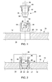
FIG. 1 is an exploded side view of a sectioned pipe wall of a pipe, with a sensor that can be embedded in the pipe wall in an exemplary embodiment of the invention using an insert and a locking nut. -
FIG. 2 is a side view of a sectioned pipe wall of a pipe, with a sensor embedded in the pipe wall, in one exemplary embodiment of the invention corresponding toFIG. 1 . -
FIG. 3 is an exploded side view of a sectioned pipe wall of a pipe, with a sensor that can be embedded in the pipe wall, in another exemplary embodiment of the invention. -
FIG. 4 is a partially sectioned side view of a pipe wall with a sensor embedded in the pipe wall, in one embodiment corresponding toFIG. 3 . -
FIG. 1 is an exploded side view of a sectionedpipe wall 12 of apipe 10, with asensor 30 that can be embedded in thepipe wall 12 in an exemplary embodiment of the invention using aninsert 20 and alocking nut 40. Thesensor 30 can be one from a variety of sensors. Some such devices include pressure sensors, flow rate meters, flow volume meters, temperature meters, moisture and humidity meters, sand or mud detectors, and fluid concentration meters. An example of a sensor that can be mounted according to this method includes a piezoresistive pressure sensor with a piezoresistive transducer. Another example of a sensor includes a resonating device, such as a trench etched resonant pressure sensor ("TERPS"). The sensors can be shaped variously. In one embodiment, the diameter or width of asensor tip 33 is approximately 0.5 inches (12.7 mm). Thesensor tip 33 can be exposed to theinterior 16 of thepipe 10. Thesensor 30 can have acollar 38, or acollar 38 can be fastened to thesensor 30, such as by welding thecollar 38 to and/or around thesensor 30. Thesensor 30 can have atapered surface 39 between thecollar 38 and thesensor tip 33. - The
sensor 30 can have or can be attached toelectrical wires 36 to communicate electrical signals from thesensor 30. - The
pipe wall 12 can be made of a material suitable for the particular application. In the subsea oil industry, for example, steel, a superalloy, or another high-performance alloy, such as an austenitic nickel-chromium-based superalloy can be used. Other materials suitable for the application and industry can also be used. Thepipe wall 12 can be of varying thicknesses. In one example of a subsea oil drilling application, thepipe wall 12 can be between 0.25 inches (6.35 mm) and 0.375 inches (9.525 mm) thick. A section of thepipe wall 12 can be removed, such as by boring a hole through thepipe wall 12, to create apassage 14 through thepipe wall 12 from anouter surface 19 of thepipe wall 12 to aninner surface 18 of thepipe wall 12. - The
insert 20 can be sized and shaped on the outside to fit into thepipe wall 12 in thepassage 14. For instance, if thepassage 14 is cylindrical, thenouter surface 22 of theinsert 20 can be shaped cylindrically as well, and dimensioned so theinsert 20 can fit snugly in thepassage 14. Alternatively, thepassage 14 of thepipe wall 12 can be shaped and sized to receive theinsert 20. - The
insert 20 can be shaped and sized to accommodate receiving thesensor 30. Theinsert 20 can have acavity 25 into which thesensor 30 can be inserted. Thecavity 25 can be defined by aninner surface 23 of theinsert 20. Theinner surface 23 can comprise an internally threadedportion 26, and atapered portion 21. The threadedportion 26 can be positioned along theinner surface 23 at the end of theinsert 40 radially outward from the center axis of thepipe 10, and thetapered portion 21 can be positioned along theinner surface 23 at the end of theinsert 40 radially inward toward the center axis of thepipe 10 from the threadedportion 26. The length of theinsert 40 in the radial direction of thepipe 10 can be longer than the thickness of thepipe wall 12 to ensure enough space for the threadedportion 26 and thetapered portion 21, and to provide extra support in securing thesensor 30 when theinsert 20 is inserted and fastened in thepipe wall 12. The thickness of theinsert 20 between theinner surface 23 and anouter surface 22 can be sufficient to accommodate the threadedportion 26 and to provide structural strength (e.g. to reduce stress, bending, or breaking, etc.) at the thinnest portion. Resultantly, theinsert 20 can be only slightly larger at it largest diameter or widest point than thesensor 30, using less material and leaving more room around thepipe 10 to locateother sensors 30, if desirable. In this way,sensors 30 can be positioned at multiple points circumferentially around thepipe 10, or in multiple points along the longitude of thepipe 10, to map pipe, fluid, and/or flow characteristics three dimensionally. -
FIG. 2 is a side view of a sectionedpipe wall 12 of apipe 10, with asensor 30 embedded in thepipe wall 12, in one exemplary embodiment of the invention corresponding toFIG. 1 . - The
insert 20 can be inserted into thepassage 14 of thepipe wall 12 so that the radially inwardly facingsurface 28 is approximately flush with theinner surface 18 of thepipe wall 12, extended beyond theinner surface 18 of thepipe wall 12, or recessed into thepipe wall 12. Positioning the radially inwardly facingsurface 28 of theinsert 20 approximately flush with theinner surface 18 of thepipe wall 12, as illustrated, can reduce any effect theinsert 20 has on the flowing fluid in thepipe 10. Positioning the radially inwardly facingsurface 28 of theinsert 20 so that theinsert 20 extends into thepipe 10 beyond theinner surface 18 of thepipe wall 12 or so that theinsert 20 is recessed in thepipe wall 12 can accommodate physical constraints engaging thepipe 10, theinsert 20, thesensor 30, and the lockingnut 40, or can accommodate any limitations of thesensor 30. Once positioned, theinsert 20 can be secured in thepipe wall 12 by welding or other known methods suitable for the structural requirements and the materials of thepipe 10 and theinsert 20. Welding can include but is not limited to gas tungsten arc welding and electric arc welding. The securement can yield a fluid seal between theinsert 20 and thepipe wall 10 that is capable of withstanding high pressures up to and exceeding 10,000 psi (68,947,573 Pa), 15,000 psi (103,421,359 Pa), or 20,000 psi (137,895,146 Pa). - The
sensor 30 can be inserted into theinsert 20, so that thesensor tip 33 is exposed to the inside of thepipe 10 and any fluid in thepipe 10. As with theinsert 20, thesensor tip 33 can be approximately flush with the inside surface of thepipe wall 12, recessed into thepipe wall 12, or extended beyond the inside surface of thepipe wall 12, depending on the design preferences and the operating conditions desirable for thesensor 30. Positioning theinsert 20 and thesensor 30 flush with the inside diameter of thepipe wall 12 can reduce impact on the flow conditions of the fluid in thepipe 10. - To obtain the proper position of the
sensor 30, the lockingnut 40 with externally threadedportion 42 that engages the internally threadedportion 26 of theinsert 20 is tightened radially inward to depress upon thecollar 38 of thesensor 30 and force thesensor 30 radially inward. The taperedsurface 39 of thesensor 30 impacts and is pressed against the taperedportion 21 of theinsert 20, making a seal, and positioning thesensor 30. The seal can withstand high pressures, including pressures in excess of 10,000 psi (68,947,573 Pa), 15,000 psi (103,421,359 Pa), or 20,000 psi (137,895,146 Pa), and beyond. The lockingnut 40 can also be unscrewed and disengaged, allowing thesensor 30 to be easily removed and/or replaced with anothersensor 30, for instance, if thesensor 30 fails. - The
insert 20 can be made of a suitable material, such as a type of steel, a superalloy, or another high-performance alloy, such as an austenitic nickel-chromium-based superalloy. Theinsert 20 can be harder than thesensor 30 so that when the taperedsurface 39 of thesensor 30 impacts and seals against the taperedportion 21 of theinsert 20, theinsert 20 is less likely to be compromised, bent or otherwise damaged. Theinsert 20 can then be reusable in removing and/or replacing thesensor 30. Alternatively, theinsert 20 can be softer than thesensor 30, so that thesensor 30 is less likely to be compromised, bent, or otherwise damaged. - A
housing 60 can be placed over thesensor 30, the lockingnut 40, and theinsert 20. Thehousing 60 can be secured to thepipe 10 so that thehousing 60 protects thesensor 30 and any electronic components. Thehousing 60 can seal out water, other fluids, contaminants, or destructive agents. -
FIG. 3 is an exploded side view of a sectionedpipe wall 12 of apipe 10, with asensor 30 that can be embedded in thepipe wall 10, in another exemplary embodiment of the invention. Thepassage 14 of thepipe wall 12 can have afirst passage portion 13 and asecond passage portion 15. Thefirst passage portion 13 can have a smaller diameter or a smaller width than the diameter or width of thesecond passage portion 15. Thefirst passage portion 13 can be sized and shaped so thesensor 30, on the radially inward side of thecollar 38, can fit in thefirst passage portion 13. For instance, if thesensor 30, on the radially inward side of thecollar 38 is cylindrical, then the first passage portion can also be cylindrical, sized slightly larger than thesensor 30 on the radially inward side of thecollar 38. - The
second passage portion 15 can be sized and shaped so thecollar 38 can fit in thesecond passage portion 15 and abut or rest against ashoulder 17 that connects between thefirst passage portion 13 and thesecond passage portion 15. Thecollar 38, for instance, can be approximately 0.75 inches (19.05 mm) or 0.875 inches (22.225 mm) in diameter. Therefore, the outer diameter of theshoulder 17 can also be approximately between 0.75 inches (19.05 mm) or 0.875 inches (22.225 mm) in diameter, or be slightly larger by an amount sufficient to allow the collar to fit in thesecond passage portion 15 and permit fastening of thesensor 30 in place. For instance, if the sensor is fastened to thepipe 10 by welding, then the clearance between thecollar 38 and the surfaces defining thesecond passage portion 15 should be limited to an amount acceptable for welding. Aspot face 11 can also be added with a larger diameter than thesecond passage portion 15 to enable room to operate and fasten thesensor 30. For instance, if thecollar 38 has a diameter of approximately 0.75 inches (19.05 mm), then thespot face 11 can have a diameter of approximately 1.0 inches (25.4 mm), which would create a ring-shaped surface of thespot face 11 0.125 inches (3.175 mm) wide. -
FIG. 4 is a partially sectioned side view of apipe wall 12 with asensor 30 embedded in thepipe wall 12, in one embodiment corresponding toFIG. 3 . Thecollar 38 can be positioned on thesensor 30, and thespot face 17 can be positioned between theouter surface 19 and theinner surface 18 of thepipe wall 12 so that thesensor tip 33 can be positioned as desirable, either flush with theinner surface 18 of thepipe wall 12, extended into thepipe 10 beyond the pipe wall 12 (e.g. toward the center axis of the pipe 10), or recessed into the pipe wall 12 (e.g. radially outward from the center axis of the pipe 10). Positioning thesensor tip 33 approximately flush with theinner surface 18 of thepipe wall 12 can reduce or prevent any impact thesensor 30 can otherwise have on the flow conditions of the fluid in thepipe 10. - The
collar 38 can also be approximately flush with theouter surface 19 of thepipe wall 12, recessed into the pipe wall 12 (e.g. toward the center axis of the pipe 10), or extended out of the pipe wall 12 (radially outward from the center axis of the pipe 10). Once thesensor 30 is positioned, with thecollar 38 abutting, resting, or being pressed against theshoulder 17, the collar can be fastened in place by such as but not limited to welding at the joint 50 between thecollar 38 and thepipe wall 10. Welding can include but is not limited to electron beam welding and laser welding. The joint 50 can make a seal that can withstand high pressures, including pressures in excess of 10,000 psi (68,947,573 Pa), 15,000 psi (103,421,359 Pa), or 20,000 psi (137,895,146 Pa), and beyond. Positioning thecollar 38 so thecollar 38 is approximately flush or slightly recessed might allow easier welding. - The total pipe area required to install a sensor in this fashion can be only slightly larger than the sensor 30 (e.g. 0.5 inches (12.7 mm) larger). Resultantly, less material is used and more room around the
pipe 10 is available to installother sensors 30, if desirable.Sensors 30 can be positioned at multiple points circumferentially around thepipe 10, or in multiple points along the longitude of thepipe 10, to map pipe, fluid, and/or flow characteristics three dimensionally. - A
housing 60 can be placed over thesensor 30 and attached to thepipe 10 to protect thesensor 30 and any electronic components. Thehousing 60 can be fastened to thepipe 10 and thehousing 60 can seal out water, other fluids, contaminants, or destructive agents. - This written description uses examples to disclose the invention, including the best mode, and also to enable any person skilled in the art to practice the invention, including making and using any devices or systems and performing any incorporated methods. The patentable scope of the invention is defined by the claims, and may include other examples that occur to those skilled in the art. Such other examples are intended to be within the scope of the claims if they have structural elements that do not differ from the literal language of the claims, or if they include equivalent structural elements with insubstantial differences from the literal language of the claims.
- Various aspects of the present invention are defined in the following numbered clauses:
- 1. An apparatus for mounting a pipe sensor, the apparatus comprising:
- a pipe with a pipe wall defining an interior, the pipe wall having an outer surface, an inner surface, and a section removed defining a passage from the outer surface through the inner surface to the interior;
- an insert disposed in the passage, the insert having an outer surface and an inner surface, the inner surface defining a cavity, the insert fastened and sealed to the pipe wall at the outer surface of the insert, the inner surface of the insert having a tapered portion;
- a sensor having a collar, the sensor disposed in the cavity of the insert, the sensor fastened and sealed to the insert, the sensor exposed to the interior of the pipe; and
- a locking nut engaged with the insert and pressed upon the collar to fasten and seal the sensor to the insert.
- 2. The apparatus of clause 1, wherein the insert has a first threaded portion, the locking nut has a second threaded portion, and the second threaded portion threads into the first threaded portion.
- 3. The apparatus of clause 1 or clause 2, wherein the sensor is positioned flush with the inner surface of the pipe wall.
- 4. The apparatus of any preceding clause, wherein the locking nut presses the sensor against the tapered portion of the insert to form a seal between the sensor and the tapered portion capable of withstanding fluid pressure.
- 5. An apparatus for mounting a pipe sensor, the apparatus comprising:
- a pipe with a pipe wall defining an interior, the pipe wall having an outer surface, an inner surface, and a section removed defining a passage from the outer surface through the inner surface to the interior; and
- a sensor having a collar, the sensor disposed in the passage, the collar welded to the pipe wall to form a fluid-impermeable seal between the collar and the pipe wall, the sensor exposed to the interior of the pipe.
- 6. The apparatus of any preceding clause, wherein the sensor is positioned flush with the inner surface of the pipe wall.
- 7. The apparatus of any preceding clause, wherein the passage is defined by a first passage surface of a first passage portion with a first diameter, a second passage surface of a second passage portion with a second diameter, and a shoulder connecting between the first passage surface and the second passage surface, and wherein the collar is pressed against the shoulder.
- 8. An apparatus for mounting a pipe sensor, the apparatus comprising:
- a pipe with a pipe wall defining an interior, the pipe wall having an outer surface, an inner surface, and a section removed defining a passage from the outer surface through the inner surface to the interior; and
- a sensor having a collar, the sensor disposed in the passage and exposed to the interior of the pipe;
- 9. The apparatus of any preceding clause, wherein the sensor is welded to the pipe wall to fasten the sensor and to form a fluid-impermeable seal between the sensor and the pipe wall.
- 10. The apparatus of any preceding clause, wherein the sensor is positioned flush with the inner surface of the pipe wall.
- 11. The apparatus of any preceding clause, wherein the passage is defined by a first passage surface with a first diameter, a second passage surface with a second diameter, and a shoulder connecting between the first passage surface and the second passage surface, and wherein the collar is pressed against the shoulder.
- 12. The apparatus of any preceding clause, further comprising:
- an insert disposed in the passage between the sensor and the pipe wall, the insert having a tapered portion; and
- a locking nut engaged with the insert and pressed upon the collar to fasten and seal the sensor to the insert.
- 13. The apparatus of any preceding clause, wherein the insert has a first threaded portion, the locking nut has a second threaded portion, and the second threaded portion threads into the first threaded portion.
- 14. The apparatus of any preceding clause, wherein the sensor is positioned flush with the inner surface of the pipe wall.
- 15. The apparatus of any preceding clause, wherein the locking nut presses the sensor against the tapered portion of the insert to form a seal between the sensor and the tapered portion capable of withstanding fluid pressure.
Claims (7)
- An apparatus for mounting a pipe sensor (30), the apparatus comprising:a pipe (10) with a pipe wall (12) defining an interior (16), the pipe wall (12) having an outer surface (19), an inner surface (18), and a section removed defining a passage (14) from the outer surface (19) through the inner surface (18) to the interior (16);an insert (20) disposed in the passage (14), the insert (20) having an outer surface (22) and an inner surface (23), the inner surface (23) of the insert (20) defining a cavity (25), the insert (20) fastened and sealed to the pipe wall (12) at the outer surface (22) of the insert (20), the inner surface (23) of the insert (20) having a tapered portion (21);a sensor (30) having a collar (38), the sensor (30) disposed in the cavity (25) of the insert (20), the sensor (30) fastened and sealed to the insert (20), the sensor (30) exposed to the interior of the pipe (10); anda locking nut (40) engaged with the insert (20) and pressed upon the collar (38) to fasten and seal the sensor (30) to the insert (20).
- The apparatus of claim 1, wherein the insert (20) has a first threaded portion (26), the locking nut (40) has a second threaded portion (42), and the second threaded portion (42) threads into the first threaded portion (26).
- The apparatus of claim 1 or claim 2, wherein the sensor (30) is positioned flush with the inner surface (18) of the pipe wall (12).
- The apparatus of any preceding claim, wherein the locking nut (40) presses the sensor (30) against the tapered portion (21) of the insert (20) to form a seal between the sensor (30) and the tapered portion (21) capable of withstanding fluid pressure.
- An apparatus for mounting a pipe sensor (30), the apparatus comprising:a pipe (10) with a pipe wall (12) defining an interior (16), the pipe wall (12) having an outer surface (19), an inner surface (18), and a section removed defining a passage (14) from the outer surface (19) through the inner surface (18) to the interior (16); anda sensor (30) having a collar (38), the sensor (30) disposed in the passage (14), the collar (38) welded to the pipe wall (12) to form a fluid-impermeable seal between the collar (38) and the pipe wall (12), the sensor (30) exposed to the interior (16) of the pipe (10).
- The apparatus of any preceding claim, wherein the sensor (30) is positioned flush with the inner surface (18) of the pipe wall (12).
- The apparatus of any preceding claim, wherein the passage (14) is defined by a first passage surface of a first passage portion (13) with a first diameter, a second passage surface of a second passage portion (15) with a second diameter, and a shoulder (17) connecting between the first passage surface and the second passage surface, and wherein the collar (38) is pressed against the shoulder (17).
Applications Claiming Priority (1)
| Application Number | Priority Date | Filing Date | Title |
|---|---|---|---|
| US12/870,028 US8733188B2 (en) | 2010-08-27 | 2010-08-27 | Apparatus for mounting pipe sensors |
Publications (3)
| Publication Number | Publication Date |
|---|---|
| EP2423556A2 true EP2423556A2 (en) | 2012-02-29 |
| EP2423556A3 EP2423556A3 (en) | 2014-07-30 |
| EP2423556B1 EP2423556B1 (en) | 2019-01-02 |
Family
ID=44735827
Family Applications (1)
| Application Number | Title | Priority Date | Filing Date |
|---|---|---|---|
| EP11178552.3A Not-in-force EP2423556B1 (en) | 2010-08-27 | 2011-08-23 | Apparatus for mounting pipe sensors |
Country Status (4)
| Country | Link |
|---|---|
| US (1) | US8733188B2 (en) |
| EP (1) | EP2423556B1 (en) |
| CN (1) | CN102563281B (en) |
| BR (1) | BRPI1103742B1 (en) |
Cited By (16)
| Publication number | Priority date | Publication date | Assignee | Title |
|---|---|---|---|---|
| EP2874779A4 (en) * | 2012-07-18 | 2016-05-04 | Daniel Measurement & Control | Method for forming a welded seal |
| KR20190083311A (en) * | 2018-01-03 | 2019-07-11 | (주)씨엠엔텍 | Function expandable insertion device installed between the pipe flanges |
| WO2021074205A1 (en) * | 2019-10-14 | 2021-04-22 | Robert Bosch Gmbh | Threaded coupling, and exhaust gas line with threaded coupling and exhaust gas sensor |
| KR102261325B1 (en) * | 2020-11-25 | 2021-06-08 | 주식회사 삼진개발 | Fire sprinkler system for apartment buildings |
| KR102262628B1 (en) * | 2020-11-25 | 2021-06-10 | (주)진전기엔지니어링 | Unmanned fire fighting integrated management system for apartment buildings |
| KR102273307B1 (en) * | 2020-11-25 | 2021-07-06 | (주)한승이엔씨 | Firefighting device for apartment houses |
| KR102273403B1 (en) * | 2020-11-26 | 2021-07-06 | (주)한국전설엔지니어링 | Firefighting management system for apartment houses using artificial intelligence |
| KR102273400B1 (en) * | 2020-11-26 | 2021-07-07 | (주)한국전설엔지니어링 | Firefighting device for apartment houses |
| KR102273404B1 (en) * | 2020-11-27 | 2021-07-07 | (주)한빛기술단 | Firefighting equipment control system of apartment houses |
| KR102274094B1 (en) * | 2020-11-26 | 2021-07-08 | 야베스텍 주식회사 | Automatic fire detection system in apartment houses |
| KR102275409B1 (en) * | 2020-11-27 | 2021-07-13 | (주)진전기엔지니어링 | Fire-fighting evacuation system of apartment houses in case of fire |
| KR102285097B1 (en) * | 2020-11-25 | 2021-08-03 | 주식회사 코담엔지니어링 | Firefighting facility automatic monitoring system in apartment houses |
| KR102285868B1 (en) * | 2020-11-25 | 2021-08-05 | (주)서영티이씨 | Fire sprinkler failure detection system in apartment houses |
| KR102288908B1 (en) * | 2020-11-26 | 2021-08-13 | (주)반석기술단 | Fire fighting water supply system in case of fire in apartment houses |
| KR102300165B1 (en) * | 2020-11-27 | 2021-09-10 | (주)동현기술사사무소 | Integrated management system for firefighting equipment in apartment houses |
| KR102300167B1 (en) * | 2020-11-27 | 2021-09-13 | (주)동현기술사사무소 | Fire stabilization system for apartment buildings |
Families Citing this family (12)
| Publication number | Priority date | Publication date | Assignee | Title |
|---|---|---|---|---|
| JP5912641B2 (en) * | 2012-02-20 | 2016-04-27 | 日本ピラー工業株式会社 | Mounting structure for fluid measurement sensor |
| US9140586B2 (en) * | 2012-09-25 | 2015-09-22 | General Electric Company | Removable sensor port insert apparatus |
| US9804002B2 (en) * | 2013-09-04 | 2017-10-31 | Cameron International Corporation | Integral sensor |
| DE102014111985A1 (en) * | 2014-08-21 | 2016-02-25 | Endress + Hauser Wetzer Gmbh + Co. Kg | Method for producing a measuring tube |
| WO2018217229A1 (en) * | 2017-05-21 | 2018-11-29 | Jms Southeast, Inc. | Process inserts, assemblies, and related methods for high velocity applications |
| FR3067107B1 (en) * | 2017-06-01 | 2019-07-05 | Eray Innovation | DEVICE AND MEASUREMENT NETWORK, FLUID TRANSPORT TUBE FIXED THEREFOR, AND FIXING METHOD |
| US10466201B2 (en) | 2018-02-01 | 2019-11-05 | FPG Industries Ohio, Inc. | Complex impedance moisture sensor and sensing method |
| US20200284765A1 (en) * | 2019-02-22 | 2020-09-10 | Onesubsea Ip Uk Limited | Oilfield production particulate monitoring assembly |
| DE102019113471A1 (en) * | 2019-05-21 | 2020-11-26 | Dr. Ing. H.C. F. Porsche Aktiengesellschaft | Connecting element for connecting two fluid lines or a fluid line to an aggregate |
| RU2718634C1 (en) * | 2019-10-23 | 2020-04-10 | Александр Александрович ЛОБАЧ | Heating radiator and corrosion indicator for heating radiator |
| CN117881951A (en) * | 2021-07-26 | 2024-04-12 | 麦克洛供水有限公司 | Pressure sensor and retrofit kit for a pressure sensor |
| WO2023055867A1 (en) * | 2021-09-29 | 2023-04-06 | Flexicon Corporation | Adaptive sensor mount assembly |
Family Cites Families (23)
| Publication number | Priority date | Publication date | Assignee | Title |
|---|---|---|---|---|
| USRE22436E (en) * | 1937-05-25 | 1944-02-15 | Pressure vessel | |
| FR1397343A (en) * | 1964-03-16 | 1965-04-30 | Commissariat Energie Atomique | Improvements at high temperature tight junctions between a magnesium-based material and another pure or alloyed metal |
| US3899782A (en) * | 1973-08-27 | 1975-08-12 | Everett L Miller | Apparatus for monitoring reaction end point |
| US3980542A (en) * | 1975-07-14 | 1976-09-14 | Petrolite Corporation | Flush mounted probe for corrosion testing |
| US4165654A (en) * | 1978-04-14 | 1979-08-28 | Hammitt Frederick G | High response rate pressure pulse sensing probe with wide temperature range applicability |
| DE8617027U1 (en) | 1986-06-26 | 1989-05-18 | Messer Griesheim Gmbh, 6000 Frankfurt, De | |
| GB8618235D0 (en) | 1986-07-25 | 1986-09-03 | Lucas Ind Plc | Pressure cylinder pipe coupling |
| US5268989A (en) | 1992-04-16 | 1993-12-07 | Texas Instruments Incorporated | Multi zone illuminator with embeded process control sensors and light interference elimination circuit |
| CN2170530Y (en) * | 1993-10-12 | 1994-06-29 | 中国石油化工总公司安全技术研究所 | Electrostatic testing alarm for oil |
| CN1112677A (en) | 1994-05-25 | 1995-11-29 | 刘瑞复 | High precision instrument for testing water content of crude oil by impedance method |
| EP1133423A1 (en) * | 1998-11-25 | 2001-09-19 | Kelsey-Hayes Company | Structure for mounting a cluster of pressure sensors upon an electro-hydraulic brake system control unit |
| CN1283780A (en) * | 2000-08-28 | 2001-02-14 | 浙江省苍南众星实业有限公司 | Method for measuring flow of fluid in pipeline and its sonic flowmeter |
| EP1415698A1 (en) | 2002-10-28 | 2004-05-06 | PTI Technologies, Inc. | Filter device using microelectromechanical system (MEMS) sensing devices |
| KR100807846B1 (en) | 2006-12-20 | 2008-02-27 | 성인식 | Semi-cylindrical type of solar collection boiler |
| JP2008261796A (en) | 2007-04-13 | 2008-10-30 | Denso Corp | Temperature-sensor-integrated pressure sensor apparatus |
| GB0721352D0 (en) | 2007-10-31 | 2007-12-12 | Expro North Sea Ltd | ubsea assembly |
| EP2065551B1 (en) | 2007-11-26 | 2014-06-25 | Schlumberger Holdings Limited (GB), | Flexible pipe |
| NO20080077L (en) | 2008-01-04 | 2009-07-06 | Harald Benestad | Sensor and detection device for use of the sensor |
| GB2456300B (en) | 2008-01-08 | 2010-05-26 | Schlumberger Holdings | Monitoring system for pipelines or risers in floating production installations |
| US9388642B2 (en) | 2008-03-05 | 2016-07-12 | Schlumberger Technology Corporation | Flexible pipe fatigue monitoring below the bend stiffener of a flexible riser |
| WO2010096714A2 (en) * | 2009-02-19 | 2010-08-26 | Touchdown Technologies, Inc. | Probe head for a microelectronic contactor assembly, the probe head having smt electronic components thereon |
| CN201354620Y (en) * | 2009-03-04 | 2009-12-02 | 谢显银 | Pressure-measurement stopcock |
| CN201429435Y (en) * | 2009-07-02 | 2010-03-24 | 唐山美伦仪表有限公司 | Ultrasonic wave flow sensor |
-
2010
- 2010-08-27 US US12/870,028 patent/US8733188B2/en not_active Expired - Fee Related
-
2011
- 2011-08-23 EP EP11178552.3A patent/EP2423556B1/en not_active Not-in-force
- 2011-08-26 BR BRPI1103742-3A patent/BRPI1103742B1/en not_active IP Right Cessation
- 2011-08-26 CN CN201110257751.8A patent/CN102563281B/en not_active Expired - Fee Related
Non-Patent Citations (1)
| Title |
|---|
| None |
Cited By (18)
| Publication number | Priority date | Publication date | Assignee | Title |
|---|---|---|---|---|
| US9816850B2 (en) | 2012-07-18 | 2017-11-14 | Daniel Measurement And Control, Inc. | Method for forming a welded seal |
| US10591338B2 (en) | 2012-07-18 | 2020-03-17 | Daniel Measurement And Control, Inc. | Welding fixture |
| EP2874779A4 (en) * | 2012-07-18 | 2016-05-04 | Daniel Measurement & Control | Method for forming a welded seal |
| KR20190083311A (en) * | 2018-01-03 | 2019-07-11 | (주)씨엠엔텍 | Function expandable insertion device installed between the pipe flanges |
| WO2021074205A1 (en) * | 2019-10-14 | 2021-04-22 | Robert Bosch Gmbh | Threaded coupling, and exhaust gas line with threaded coupling and exhaust gas sensor |
| KR102285097B1 (en) * | 2020-11-25 | 2021-08-03 | 주식회사 코담엔지니어링 | Firefighting facility automatic monitoring system in apartment houses |
| KR102261325B1 (en) * | 2020-11-25 | 2021-06-08 | 주식회사 삼진개발 | Fire sprinkler system for apartment buildings |
| KR102262628B1 (en) * | 2020-11-25 | 2021-06-10 | (주)진전기엔지니어링 | Unmanned fire fighting integrated management system for apartment buildings |
| KR102273307B1 (en) * | 2020-11-25 | 2021-07-06 | (주)한승이엔씨 | Firefighting device for apartment houses |
| KR102285868B1 (en) * | 2020-11-25 | 2021-08-05 | (주)서영티이씨 | Fire sprinkler failure detection system in apartment houses |
| KR102273403B1 (en) * | 2020-11-26 | 2021-07-06 | (주)한국전설엔지니어링 | Firefighting management system for apartment houses using artificial intelligence |
| KR102274094B1 (en) * | 2020-11-26 | 2021-07-08 | 야베스텍 주식회사 | Automatic fire detection system in apartment houses |
| KR102273400B1 (en) * | 2020-11-26 | 2021-07-07 | (주)한국전설엔지니어링 | Firefighting device for apartment houses |
| KR102288908B1 (en) * | 2020-11-26 | 2021-08-13 | (주)반석기술단 | Fire fighting water supply system in case of fire in apartment houses |
| KR102275409B1 (en) * | 2020-11-27 | 2021-07-13 | (주)진전기엔지니어링 | Fire-fighting evacuation system of apartment houses in case of fire |
| KR102273404B1 (en) * | 2020-11-27 | 2021-07-07 | (주)한빛기술단 | Firefighting equipment control system of apartment houses |
| KR102300165B1 (en) * | 2020-11-27 | 2021-09-10 | (주)동현기술사사무소 | Integrated management system for firefighting equipment in apartment houses |
| KR102300167B1 (en) * | 2020-11-27 | 2021-09-13 | (주)동현기술사사무소 | Fire stabilization system for apartment buildings |
Also Published As
| Publication number | Publication date |
|---|---|
| EP2423556B1 (en) | 2019-01-02 |
| US20120048038A1 (en) | 2012-03-01 |
| CN102563281A (en) | 2012-07-11 |
| US8733188B2 (en) | 2014-05-27 |
| BRPI1103742A2 (en) | 2015-04-07 |
| CN102563281B (en) | 2015-12-09 |
| EP2423556A3 (en) | 2014-07-30 |
| BRPI1103742B1 (en) | 2020-09-15 |
Similar Documents
| Publication | Publication Date | Title |
|---|---|---|
| US8733188B2 (en) | Apparatus for mounting pipe sensors | |
| AU2019257498B2 (en) | Pipe fitting with sensor | |
| US20230375426A1 (en) | Pressure monitoring system for wet barrel hydrant | |
| US11971318B2 (en) | Pressure monitoring system and housing therefor | |
| US4019371A (en) | Apparatus and method for externally testing conduit connections | |
| US10578503B2 (en) | System and methods for strain detection in a coupling | |
| JP5201513B2 (en) | Pressure sensor unit | |
| US6478087B2 (en) | Apparatus and method for sensing the profile and position of a well component in a well bore | |
| JP4227550B2 (en) | Pressure sensor and manufacturing method thereof | |
| RU2351906C2 (en) | Working process guidance data unit | |
| US10330551B2 (en) | Pass-throughs for use with sensor assemblies, sensor assemblies including at least one pass-through and related methods | |
| KR101341442B1 (en) | Smart pipe with water leak perception sensor | |
| EP3229004B1 (en) | Pressure sensor | |
| USRE30311E (en) | Apparatus and method for externally testing conduit connections | |
| US20070139039A1 (en) | Stick position sensor and replacement process | |
| CN100504328C (en) | Connectors for measuring instruments and a measuring probe provided with a connector of this type | |
| EP4215677A1 (en) | Outer housing for a pressure monitoring system | |
| JP6037112B2 (en) | Differential pressure / pressure transmitter | |
| US5955677A (en) | Metal seal for pressure transducer | |
| JP2010151620A (en) | Component force meter | |
| JP4850334B2 (en) | Flow sensor for piping |
Legal Events
| Date | Code | Title | Description |
|---|---|---|---|
| AK | Designated contracting states |
Kind code of ref document: A2 Designated state(s): AL AT BE BG CH CY CZ DE DK EE ES FI FR GB GR HR HU IE IS IT LI LT LU LV MC MK MT NL NO PL PT RO RS SE SI SK SM TR |
|
| AX | Request for extension of the european patent |
Extension state: BA ME |
|
| PUAI | Public reference made under article 153(3) epc to a published international application that has entered the european phase |
Free format text: ORIGINAL CODE: 0009012 |
|
| RIC1 | Information provided on ipc code assigned before grant |
Ipc: G01L 19/00 20060101ALI20140206BHEP Ipc: F16L 41/00 20060101AFI20140206BHEP |
|
| PUAL | Search report despatched |
Free format text: ORIGINAL CODE: 0009013 |
|
| AK | Designated contracting states |
Kind code of ref document: A3 Designated state(s): AL AT BE BG CH CY CZ DE DK EE ES FI FR GB GR HR HU IE IS IT LI LT LU LV MC MK MT NL NO PL PT RO RS SE SI SK SM TR |
|
| AX | Request for extension of the european patent |
Extension state: BA ME |
|
| RIC1 | Information provided on ipc code assigned before grant |
Ipc: G01L 19/00 20060101ALI20140626BHEP Ipc: F16L 41/00 20060101AFI20140626BHEP |
|
| 17P | Request for examination filed |
Effective date: 20150130 |
|
| RBV | Designated contracting states (corrected) |
Designated state(s): AL AT BE BG CH CY CZ DE DK EE ES FI FR GB GR HR HU IE IS IT LI LT LU LV MC MK MT NL NO PL PT RO RS SE SI SK SM TR |
|
| GRAP | Despatch of communication of intention to grant a patent |
Free format text: ORIGINAL CODE: EPIDOSNIGR1 |
|
| STAA | Information on the status of an ep patent application or granted ep patent |
Free format text: STATUS: GRANT OF PATENT IS INTENDED |
|
| INTG | Intention to grant announced |
Effective date: 20180507 |
|
| GRAS | Grant fee paid |
Free format text: ORIGINAL CODE: EPIDOSNIGR3 |
|
| GRAA | (expected) grant |
Free format text: ORIGINAL CODE: 0009210 |
|
| STAA | Information on the status of an ep patent application or granted ep patent |
Free format text: STATUS: THE PATENT HAS BEEN GRANTED |
|
| AK | Designated contracting states |
Kind code of ref document: B1 Designated state(s): AL AT BE BG CH CY CZ DE DK EE ES FI FR GB GR HR HU IE IS IT LI LT LU LV MC MK MT NL NO PL PT RO RS SE SI SK SM TR |
|
| REG | Reference to a national code |
Ref country code: GB Ref legal event code: FG4D |
|
| REG | Reference to a national code |
Ref country code: CH Ref legal event code: EP Ref country code: AT Ref legal event code: REF Ref document number: 1084826 Country of ref document: AT Kind code of ref document: T Effective date: 20190115 |
|
| REG | Reference to a national code |
Ref country code: IE Ref legal event code: FG4D |
|
| REG | Reference to a national code |
Ref country code: DE Ref legal event code: R096 Ref document number: 602011055301 Country of ref document: DE |
|
| REG | Reference to a national code |
Ref country code: NL Ref legal event code: MP Effective date: 20190102 |
|
| REG | Reference to a national code |
Ref country code: LT Ref legal event code: MG4D |
|
| REG | Reference to a national code |
Ref country code: NO Ref legal event code: T2 Effective date: 20190102 |
|
| REG | Reference to a national code |
Ref country code: AT Ref legal event code: MK05 Ref document number: 1084826 Country of ref document: AT Kind code of ref document: T Effective date: 20190102 |
|
| PG25 | Lapsed in a contracting state [announced via postgrant information from national office to epo] |
Ref country code: NL Free format text: LAPSE BECAUSE OF FAILURE TO SUBMIT A TRANSLATION OF THE DESCRIPTION OR TO PAY THE FEE WITHIN THE PRESCRIBED TIME-LIMIT Effective date: 20190102 |
|
| PG25 | Lapsed in a contracting state [announced via postgrant information from national office to epo] |
Ref country code: PT Free format text: LAPSE BECAUSE OF FAILURE TO SUBMIT A TRANSLATION OF THE DESCRIPTION OR TO PAY THE FEE WITHIN THE PRESCRIBED TIME-LIMIT Effective date: 20190502 Ref country code: SE Free format text: LAPSE BECAUSE OF FAILURE TO SUBMIT A TRANSLATION OF THE DESCRIPTION OR TO PAY THE FEE WITHIN THE PRESCRIBED TIME-LIMIT Effective date: 20190102 Ref country code: FI Free format text: LAPSE BECAUSE OF FAILURE TO SUBMIT A TRANSLATION OF THE DESCRIPTION OR TO PAY THE FEE WITHIN THE PRESCRIBED TIME-LIMIT Effective date: 20190102 Ref country code: PL Free format text: LAPSE BECAUSE OF FAILURE TO SUBMIT A TRANSLATION OF THE DESCRIPTION OR TO PAY THE FEE WITHIN THE PRESCRIBED TIME-LIMIT Effective date: 20190102 Ref country code: LT Free format text: LAPSE BECAUSE OF FAILURE TO SUBMIT A TRANSLATION OF THE DESCRIPTION OR TO PAY THE FEE WITHIN THE PRESCRIBED TIME-LIMIT Effective date: 20190102 Ref country code: ES Free format text: LAPSE BECAUSE OF FAILURE TO SUBMIT A TRANSLATION OF THE DESCRIPTION OR TO PAY THE FEE WITHIN THE PRESCRIBED TIME-LIMIT Effective date: 20190102 |
|
| PG25 | Lapsed in a contracting state [announced via postgrant information from national office to epo] |
Ref country code: IS Free format text: LAPSE BECAUSE OF FAILURE TO SUBMIT A TRANSLATION OF THE DESCRIPTION OR TO PAY THE FEE WITHIN THE PRESCRIBED TIME-LIMIT Effective date: 20190502 Ref country code: GR Free format text: LAPSE BECAUSE OF FAILURE TO SUBMIT A TRANSLATION OF THE DESCRIPTION OR TO PAY THE FEE WITHIN THE PRESCRIBED TIME-LIMIT Effective date: 20190403 Ref country code: RS Free format text: LAPSE BECAUSE OF FAILURE TO SUBMIT A TRANSLATION OF THE DESCRIPTION OR TO PAY THE FEE WITHIN THE PRESCRIBED TIME-LIMIT Effective date: 20190102 Ref country code: HR Free format text: LAPSE BECAUSE OF FAILURE TO SUBMIT A TRANSLATION OF THE DESCRIPTION OR TO PAY THE FEE WITHIN THE PRESCRIBED TIME-LIMIT Effective date: 20190102 Ref country code: LV Free format text: LAPSE BECAUSE OF FAILURE TO SUBMIT A TRANSLATION OF THE DESCRIPTION OR TO PAY THE FEE WITHIN THE PRESCRIBED TIME-LIMIT Effective date: 20190102 Ref country code: BG Free format text: LAPSE BECAUSE OF FAILURE TO SUBMIT A TRANSLATION OF THE DESCRIPTION OR TO PAY THE FEE WITHIN THE PRESCRIBED TIME-LIMIT Effective date: 20190402 |
|
| REG | Reference to a national code |
Ref country code: DE Ref legal event code: R097 Ref document number: 602011055301 Country of ref document: DE |
|
| PG25 | Lapsed in a contracting state [announced via postgrant information from national office to epo] |
Ref country code: RO Free format text: LAPSE BECAUSE OF FAILURE TO SUBMIT A TRANSLATION OF THE DESCRIPTION OR TO PAY THE FEE WITHIN THE PRESCRIBED TIME-LIMIT Effective date: 20190102 Ref country code: AT Free format text: LAPSE BECAUSE OF FAILURE TO SUBMIT A TRANSLATION OF THE DESCRIPTION OR TO PAY THE FEE WITHIN THE PRESCRIBED TIME-LIMIT Effective date: 20190102 Ref country code: CZ Free format text: LAPSE BECAUSE OF FAILURE TO SUBMIT A TRANSLATION OF THE DESCRIPTION OR TO PAY THE FEE WITHIN THE PRESCRIBED TIME-LIMIT Effective date: 20190102 Ref country code: EE Free format text: LAPSE BECAUSE OF FAILURE TO SUBMIT A TRANSLATION OF THE DESCRIPTION OR TO PAY THE FEE WITHIN THE PRESCRIBED TIME-LIMIT Effective date: 20190102 Ref country code: DK Free format text: LAPSE BECAUSE OF FAILURE TO SUBMIT A TRANSLATION OF THE DESCRIPTION OR TO PAY THE FEE WITHIN THE PRESCRIBED TIME-LIMIT Effective date: 20190102 Ref country code: AL Free format text: LAPSE BECAUSE OF FAILURE TO SUBMIT A TRANSLATION OF THE DESCRIPTION OR TO PAY THE FEE WITHIN THE PRESCRIBED TIME-LIMIT Effective date: 20190102 Ref country code: SK Free format text: LAPSE BECAUSE OF FAILURE TO SUBMIT A TRANSLATION OF THE DESCRIPTION OR TO PAY THE FEE WITHIN THE PRESCRIBED TIME-LIMIT Effective date: 20190102 |
|
| PLBE | No opposition filed within time limit |
Free format text: ORIGINAL CODE: 0009261 |
|
| STAA | Information on the status of an ep patent application or granted ep patent |
Free format text: STATUS: NO OPPOSITION FILED WITHIN TIME LIMIT |
|
| PG25 | Lapsed in a contracting state [announced via postgrant information from national office to epo] |
Ref country code: SM Free format text: LAPSE BECAUSE OF FAILURE TO SUBMIT A TRANSLATION OF THE DESCRIPTION OR TO PAY THE FEE WITHIN THE PRESCRIBED TIME-LIMIT Effective date: 20190102 |
|
| 26N | No opposition filed |
Effective date: 20191003 |
|
| PG25 | Lapsed in a contracting state [announced via postgrant information from national office to epo] |
Ref country code: SI Free format text: LAPSE BECAUSE OF FAILURE TO SUBMIT A TRANSLATION OF THE DESCRIPTION OR TO PAY THE FEE WITHIN THE PRESCRIBED TIME-LIMIT Effective date: 20190102 |
|
| PG25 | Lapsed in a contracting state [announced via postgrant information from national office to epo] |
Ref country code: TR Free format text: LAPSE BECAUSE OF FAILURE TO SUBMIT A TRANSLATION OF THE DESCRIPTION OR TO PAY THE FEE WITHIN THE PRESCRIBED TIME-LIMIT Effective date: 20190102 |
|
| PG25 | Lapsed in a contracting state [announced via postgrant information from national office to epo] |
Ref country code: CH Free format text: LAPSE BECAUSE OF NON-PAYMENT OF DUE FEES Effective date: 20190831 Ref country code: LU Free format text: LAPSE BECAUSE OF NON-PAYMENT OF DUE FEES Effective date: 20190823 Ref country code: MC Free format text: LAPSE BECAUSE OF FAILURE TO SUBMIT A TRANSLATION OF THE DESCRIPTION OR TO PAY THE FEE WITHIN THE PRESCRIBED TIME-LIMIT Effective date: 20190102 Ref country code: LI Free format text: LAPSE BECAUSE OF NON-PAYMENT OF DUE FEES Effective date: 20190831 |
|
| REG | Reference to a national code |
Ref country code: BE Ref legal event code: MM Effective date: 20190831 |
|
| PG25 | Lapsed in a contracting state [announced via postgrant information from national office to epo] |
Ref country code: IE Free format text: LAPSE BECAUSE OF NON-PAYMENT OF DUE FEES Effective date: 20190823 Ref country code: FR Free format text: LAPSE BECAUSE OF NON-PAYMENT OF DUE FEES Effective date: 20190831 |
|
| PG25 | Lapsed in a contracting state [announced via postgrant information from national office to epo] |
Ref country code: BE Free format text: LAPSE BECAUSE OF NON-PAYMENT OF DUE FEES Effective date: 20190831 |
|
| PGFP | Annual fee paid to national office [announced via postgrant information from national office to epo] |
Ref country code: GB Payment date: 20200722 Year of fee payment: 10 Ref country code: DE Payment date: 20200721 Year of fee payment: 10 Ref country code: NO Payment date: 20200724 Year of fee payment: 10 |
|
| PGFP | Annual fee paid to national office [announced via postgrant information from national office to epo] |
Ref country code: IT Payment date: 20200721 Year of fee payment: 10 |
|
| PG25 | Lapsed in a contracting state [announced via postgrant information from national office to epo] |
Ref country code: CY Free format text: LAPSE BECAUSE OF FAILURE TO SUBMIT A TRANSLATION OF THE DESCRIPTION OR TO PAY THE FEE WITHIN THE PRESCRIBED TIME-LIMIT Effective date: 20190102 |
|
| PG25 | Lapsed in a contracting state [announced via postgrant information from national office to epo] |
Ref country code: HU Free format text: LAPSE BECAUSE OF FAILURE TO SUBMIT A TRANSLATION OF THE DESCRIPTION OR TO PAY THE FEE WITHIN THE PRESCRIBED TIME-LIMIT; INVALID AB INITIO Effective date: 20110823 Ref country code: MT Free format text: LAPSE BECAUSE OF FAILURE TO SUBMIT A TRANSLATION OF THE DESCRIPTION OR TO PAY THE FEE WITHIN THE PRESCRIBED TIME-LIMIT Effective date: 20190102 |
|
| REG | Reference to a national code |
Ref country code: DE Ref legal event code: R119 Ref document number: 602011055301 Country of ref document: DE |
|
| REG | Reference to a national code |
Ref country code: NO Ref legal event code: MMEP |
|
| GBPC | Gb: european patent ceased through non-payment of renewal fee |
Effective date: 20210823 |
|
| PG25 | Lapsed in a contracting state [announced via postgrant information from national office to epo] |
Ref country code: NO Free format text: LAPSE BECAUSE OF NON-PAYMENT OF DUE FEES Effective date: 20210831 |
|
| PG25 | Lapsed in a contracting state [announced via postgrant information from national office to epo] |
Ref country code: MK Free format text: LAPSE BECAUSE OF FAILURE TO SUBMIT A TRANSLATION OF THE DESCRIPTION OR TO PAY THE FEE WITHIN THE PRESCRIBED TIME-LIMIT Effective date: 20190102 |
|
| PG25 | Lapsed in a contracting state [announced via postgrant information from national office to epo] |
Ref country code: IT Free format text: LAPSE BECAUSE OF NON-PAYMENT OF DUE FEES Effective date: 20210823 Ref country code: GB Free format text: LAPSE BECAUSE OF NON-PAYMENT OF DUE FEES Effective date: 20210823 Ref country code: DE Free format text: LAPSE BECAUSE OF NON-PAYMENT OF DUE FEES Effective date: 20220301 |